CHINA - cbdb.org.br · Hydraulics Station which is 124km blew the Xiluodu Dam site from June 1939...
20
1 KEY TECHNOLOGIES AND ENGINEERING PRACTICE FOR TAIL DOWN SPILLWAY TUNNEL WITH HIGH FLOW RATE AND LARGE DISCHARGE CAPACITY Nie Qinghua 1 , Li Guo 2 ,Fan Qixiang 3 1Director, Xiluodu Project Construction Dept., CTG 2 Engineer, CTG 3 Executive Vice President, China Three Gorges Corporation (CTG) CHINA Abstract:Recent years, a group of large water conservancy and hydropower projects developed and implemented in narrow valley areas in China. In terms of flood discharge, these projects feature high water head, large flow capacity, high flow rate and strong flood discharge power. Flood discharge and energy dissipation facilities are technologically challenged by layout, shape selection, design, construction, maintenance and operation, etc. Based on the construction practice of spillway tunnel project of Xiluodu Hydropower Station, this article mainly presents the problems addressed and successful experience summarized in the process of design and construction. From a perspective of case study, this article sets out achievements of large spillway tunnels in respect of layout and shapedesign, study on aerationfor preventing cavitationerosion, new material and new technology application, construction technology innovation, and project management measures, etc. Practice show that, a series of technologies and management measures that have been adoptedare successful, and have ensured spillway tunnels are completed smoothly and achieve the high-quality goal of excellent projects. Key words: high-speed water flow; water conservancy &hydropower projects; key technologies; case study; spillway tunnel IMPORTANCEOF FLOOD DISCHARGE AND ENERGY DISSIPATION OF HIGH DAMS AND LARGE RESERVOIRS China’s reservoir dams rank first both in number and size. The safety of high dams and large reservoirs are closely related to the life and property safety of the
Transcript of CHINA - cbdb.org.br · Hydraulics Station which is 124km blew the Xiluodu Dam site from June 1939...

1
KEY TECHNOLOGIES AND ENGINEERING PRACTICE FOR TAIL DOWN
SPILLWAY TUNNEL WITH HIGH FLOW RATE AND LARGE DISCHARGE
CAPACITY
Nie Qinghua1, Li Guo2,Fan Qixiang3
1Director, Xiluodu Project Construction Dept., CTG
2 Engineer, CTG
3 Executive Vice President, China Three Gorges Corporation (CTG)
CHINA
Abstract:Recent years, a group of large water conservancy and hydropower
projects developed and implemented in narrow valley areas in China. In terms of
flood discharge, these projects feature high water head, large flow capacity, high
flow rate and strong flood discharge power. Flood discharge and energy
dissipation facilities are technologically challenged by layout, shape selection,
design, construction, maintenance and operation, etc. Based on the construction
practice of spillway tunnel project of Xiluodu Hydropower Station, this article
mainly presents the problems addressed and successful experience summarized
in the process of design and construction. From a perspective of case study, this
article sets out achievements of large spillway tunnels in respect of layout and
shapedesign, study on aerationfor preventing cavitationerosion, new material and
new technology application, construction technology innovation, and project
management measures, etc. Practice show that, a series of technologies and
management measures that have been adoptedare successful, and have ensured
spillway tunnels are completed smoothly and achieve the high-quality goal of
excellent projects.
Key words: high-speed water flow; water conservancy &hydropower projects;
key technologies; case study; spillway tunnel
IMPORTANCEOF FLOOD DISCHARGE AND ENERGY DISSIPATION OF HIGH
DAMS AND LARGE RESERVOIRS
China’s reservoir dams rank first both in number and size. The safety of high
dams and large reservoirs are closely related to the life and property safety of the

2
downstream people, the lifeblood of national economy, and even the ecological
environment. Over the years, in spite of no dam breakat medium- and large-sized
hydropower stations in China, major engineering accidents have occurred several
times[1]. China’s hydropower resources are mostly found in alpine and gorge
areas in western part of the country. In recent years, a group of super-high dams
close to and even exceeding 300m started construction one after another.For high
dam flood discharge, such problems as energy dissipation and erosion control,
atomization safety, and high-speed water flow cavitation damage are among the
problems to be solved as a focus through engineering design.
High dam flood discharge takes three forms, namely dam discharge, bank
side discharge, dam and bank side combined discharge, and in whatever form,
there have been frequent flood releasing structure damage examples caused by
high-speed water flow[2]. Therefore, the flood discharge and energy dissipation,
and safe operation of high dams and large reservoirs have been a key concern in
the field of water conservancy and hydropower projects.
1 FLOOD RELEASING STRUCTURES LAYOUT OF XILUODU STATION
Xiluodu Hydropower Station is located in the Xiluodu Gorge at the lower
reach of Jinsha River. According to the measured data statistics for Pingshan
Hydraulics Station which is 124km blew the Xiluodu Dam site from June 1939 to
May 1998, runoff Eigen values are shown as Table 1.
Table 1 Runoff Eigen Values of Xiluodu Hydropower Station[3]
Multi-year
Average Flow
Rate
Multi-year
Average Annual
Runoff Volume
Max. Flow Rate
Measured
Min. Flow Rate
Measured
Historical Max.
Flood Flow Rate
Investigated
4570 m3/s 144 billion m3 29000 m3/s 1060 m3/s 36900 m3/s
In terms of flood discharge and energy dissipation, Xiluodu Hydropower
Station has high water head, large discharge capacity, narrow valley, and strong
discharge power. To adopt a safe and reliable flood discharge manner, arrange
flood releasing structuresreasonably, and solve the downstream energy
dissipation and cavitation erosion control problems is one of the key issues in the
design. In accordance with the requirement of total discharge capacity of the
Complex, combining the topographic and geologic conditions, hydraulic
characteristics, reservoir regulating and operating mode and considering the river
diversion in the middle and later periods, flood releasing structuresare arranged in

3
the principle of “scattered flood discharge, energy dissipation in separate areas”,
consisting of “7 surface outlets + 8 bottom outlets on the dam, and 2 spillway
tunnel on each of the left and right banks”(Table 2). Discharge capacity is
distributed across the flood releasing structure as follows: maximum discharge
capacity of the dam is about 32300 m3/s, or about 66% of the total discharge
capacity;maximum discharge capacity of four spillway tunnels is about16600
m3/s,or about 34% of the total discharge capacity. The discharge capacity meets
the designed flood requirements, and the needs of safe operation of the Complex
can be met.
Table 2Features of Spillway Facilitiesat the Complex[3]
Flood Releasing Structure Dam Outlet
Spillway Tunnel Surface Outlet Bottom Outlet
Number of Outlets (Tunnels) 7 8 4
Section Dimension (m×m) 12.5×13.5 6.0×6.7 14.0×12.0
Intake Height (m) 586.50 490.70~502.80 545.00
Single-outlet (tunnel) Discharge
Capacity (m3/s)
Designed/Exceptional
1326/2771 1545/1610 3858/4162
2 NATIONAL AND INTERNATIONAL SPILLWAY ENGINEERING PRACTICE
AND FEATURES OF XILUODU SPILLWAY TUNNEL
For high dams, spillway tunnels tend to be important supplements to dam
spillway facilities, and the overall layout of flood releasing structureoften consist of
dam spillway and bank side spillway. The vertical layout of spillway tunnel mainly
falls into “head down”and “tail down” types. And there are also chute
type,submerged orificeoblique/straight line type, and swirl shaft type. These
various type of spillway tunnels are widely applied innational and international
large hydropower stations[4,5,6,7,8,9]. Specific form and shapeof the spillway tunnel
depend upon the layout, topographic and geologic conditions, and total discharge
capacity of the Complex, etc.
It is noteworthy that, with the design of large “head down” type spillway tunnel
such as Ertan Hydropower Station, relatively severe cavitation damage happened
nearby thecircle arc sectionof spillway tunnel in several projects, with the longest
damage up to several hundred meters [4]. This was due to the poor knowledge
about cavitation and cavitation erosion caused by high-speed water flow, no

4
application of aerator or insufficient study on the shape of aeratorin early projects.
In addition to aeration for preventing cavitation erosion, the “tail down”type layout
adopted in recent years is also a better solution. Compared with the previously
used “head down”type, most sections in a “tail down” spillway tunnelare flat
tunnels with relatively gentle slope, and lower water flow rate; and the length of
high-speed area of abrupt slope section is limited, which is convenient to arrange
aerators in a concentrated way;and the positions most easily exposed to
cavitation damage are located near the exitas possible as practical, and far from
the dam and other buildings, thus the cavitation damage will not pose a threat on
the safety of the whole tunnel and the dam, even though it occurs at thecircle
arcsection. Therefore, the“tail down” shape is an innovation of design concept and
summary of successful experience for the layout of spillway tunnels with large flow
capacity and high flow rate during long-term engineering practice.
Xiluodu Hydropower Station lies in an alpine and gorge area, where the
narrow river valley disables the arrangement of structures at the Complex, and the
topographic features determines that only high arch dams can be arranged in the
river valley; As dam outlets have limited flood discharge capacity, spillway tunnel
has been one of the main flood discharge facilities for its flexible layout mode and
adaptability to the landform of gorge.The project size, flood discharge power and
technical difficulty of Xiluodu Spillway Tunnel come out top at home and abroad.
The features of high water head, high flow rate, large discharge capacity pose
extremely high requirements on design and construction quality, with main difficult
problems to be solved as: (1) In terms of design, first, the spillway tunnel’s layout
and shape problems shall be solved by considering all factors including
topographic and geological conditions, distribution of structures at the Complex,
and flood discharge capacity; second, the cavitation and cavitation erosion
problems caused by high-speed water flow shall be solved through reasonable
arrangement of aerators and study on appropriate shape. (2) In terms of
construction, study is needed to adopt advanced and efficient construction
solution and building materials with excellent performance, in order to solve the
problems of large cave chamber excavation, concrete structure shape control,
high-grade concrete construction as well as temperature control and crack
prevention. (3) In terms of management, comprehensive management measures
are needed in respect of technology, progress, quality, and safety, etc.

5
Construction objectives of the spillway tunnel project shall be achieved on
schedule, which is guaranteed by technological measures and lean management,
and preceded by ensuring quality and safety.This article focuses on the
presenting the key technological problems solved in and successful management
experience of Xiluodu Spillway Tunnel project from the foregoing aspects.
3 MAIN DESIGN CHALLENGES AND SOLUTIONS
3.1 Spillway tunnel layout, shapeand relationship with the Complex
In the layout of a spillway tunnel, factors to be considered include topographic
and geological conditions, requirement of flood discharge capacity, Orificelayout,
design of lock gate structure, energy dissipation and erosion prevention at the
outlet, and the like. And water flow in the tunnel shall be as “even, smooth, and
straight” as possible to ensure smooth discharge. The Xiluodu Complex lies in
the middle part of 4km straight watercourse, with precipitous gorges on banks.
But there are moderately gentle slopes on left and right banks about 500m
upstream the dam site at elevation of 535~640m, where are suitable for
arranging spillway tunnel entrance. Combining the layout of the Complex, the
spillway tunnel makes a horizontal turn by pressure flow section, bypassing the
abutment of the arch dam, and connecting with straight free flow section;
combining the topographic condition at the outlet, the “tail down ramp in the
tunnel” type is used to concentrate about 70% of total water head difference at
the tail end which accounts for 25% of the total tunnel length.This type of layout
reduces the range of high-speed flow area and allows easier aeration for
preventing cavitation erosion, and contributes to handle high-speed water flow
problems in a concentrated way. The exit is located downstream the tailrace
tunnel of the plant, far from other permanent buildings. Water flow enters the
river bed through ski-jump energy dissipation, with better water flow coming into
the channel.Spillway tunnels are roughly arranged symmetrically on left and right
banks. Axes of tunnel on single bank are parallel, with center-to-center spacing
of about 50m, and tunnel length ranging from about 1.4km to 1.8km (Fig.1).
Hydraulic model verifies that, with the foregoing layout, the pressure flow section
ensures smooth and steady flow regime in the tunnel, thus allows flexible and
convenient entrance and exit layout, and shortens the tunnel line.

6
Fig.1 Plane Layout Sketch Map of Xiluodu Hydropower Station
Four spillway tunnels have the same structural styles, consisting of intake
tower, pressure flow section, underground service gate chamber, free flow section,
tail down section, open channel and flip bucket, etc. (Fig. 2). (1) The intake tower
lies between the plant’s water inlet and the dam, which includes contractive
funnels on the top and two sides to ensure smooth and steady water flow regime.
(2) The pressure flow section is a round section with lined diameter of 15m,
bending radius of 200m, with its end connecting with the underground service
gate chamber through “round to square” transition section. (3) The free flow
section follows the arch-shaped service gate immediately, in a city gate shape
with lined section dimension of 14m×19m (width×height), withfloor’s longitudinal
slope of 2.3%. (4) The tail down section is complicated in shape, with the section
dimension same as the free flow section, and consisting of the Ogee curve section,
steepslope section, circle arc sectionandgentle slope section. Of which, the Ogee
section is a parabola of the equationZ=(X2/400)+0.023X, with maximum gradient
of the steep slope section at 22.457°,circle arc section radius of 300m, and
longitudinal slope ofgentle slopesection at 8%. High-speed water flows often
appear here,with the flow rate rising from 25m/s at the starting point of the Ogee
section to nearly 50m/s at the end ofcircle arc section. To reduce and eliminate
any cavitation damage to the lining structure, an air supply tunnel is constructed at
the starting end of the Ogee section, which connects with the ground. And
Plant
Plant
Outgoing Line Yard
Double-curvature Arch Dam
Left-bank Spillway Tunnel
Right-bank Spillway Tunnel
Transformer Chamber
Surge Chamber Tailrace Tunnel

7
3~4aerators are provided for each high-flow-rate area according to their length. (5)
The elevation of spillway tunnel exit is higher than the downstream water
level.Considering the topographic and geologic conditions in the energy
dissipation area in downstream watercourse, fall point of water jet, downstream
water coming into channel, and other factors, it is cost-effective to apply diffused
energy dissipation by diffusedtrajectory jet.
Fig.2 Longitudinal Profile of the Spillway Tunnel
3.2 Model test of high-speed water flow and aerator shape optimization
When the reservoir water level of Xiluodu Hydropower Station is higher than
580m, the number of most water flow cavitations at the tail down section
decreases to 0.3 below. Thus, aeration measures must be taken to control
cavitation erosion.
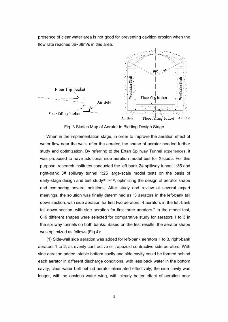
In the bidding design stage, totally 3 aerators were provided for the left-bank
spillway tunnel and 4 aerators for the right-bank spillway tunnel in the high-speed
flow area below the Ogee section, all in the form of bottom aeration through
combined flip and falling buckets on the floor; and an air hole was provided on
each of the left and right sides below the buckets to connect with the remaining
space of the tunnel top via ventilation shafts in the sidewalls on both sides to
supply air (Fig.3). According to the results of 1:45 model test conducted by China
Institute of Water Resources and Hydropower Research (IWHR)[10], in this manner
of bottom aerator only, four aerators could all form stable aeration cavities when
the reservoir water level is at 580m and the designed flood water level is at
600.63m. But there are still two problems: (1) after the first aerator, there’s certain
backwater in the bottom cavity, with smaller air speed and ventilator capacity in
the ventilation shaft, and poor aeration effect; (2)after the second aerator, aeration
is not enough in the main flow area of side-walls in the bottom cavity, andthe
8
presence of clear water area is not good for preventing cavition erosion when the
flow rate reaches 36~38m/s in this area.
Fig. 3 Sketch Map of Aerator in Bidding Design Stage
When in the implementation stage, in order to improve the aeration effect of
water flow near the walls after the aerator, the shape of aerator needed further
study and optimization. By referring to the Ertan Spillway Tunnel experiences, it
was proposed to have additional side aeration model test for Xiluodu. For this
purpose, research institutes conducted the left-bank 2# spillway tunnel 1:35 and
right-bank 3# spillway tunnel 1:25 large-scale model tests on the basis of
early-stage design and test study[11,12,13], optimizing the design of aerator shape
and comparing several solutions. After study and review at several expert
meetings, the solution was finally determined as “3 aerators in the left-bank tail
down section, with side aeration for first two aerators, 4 aerators in the left-bank
tail down section, with side aeration for first three aerators.” In the model test,
6~9 different shapes were selected for comparative study for aerators 1 to 3 in
the spillway tunnels on both banks. Based on the test results, the aerator shape
was optimized as follows (Fig.4):
(1) Side-wall side aeration was added for left-bank aerators 1 to 3, right-bank
aerators 1 to 2, as evenly contractive or trapezoid contractive side aerators. With
side aeration added, stable bottom cavity and side cavity could be formed behind
each aerator in different discharge conditions, with less back water in the bottom
cavity, clear water belt behind aerator eliminated effectively; the side cavity was
longer, with no obvious water wing, with clearly better effect of aeration near

9
sidewalls than the result of test with bottom aeration only.
(2) The bottom aeration shape of some aerators was optimized. The gradient
and height of floor flip bucket were adjusted, or the former continuous flip buckets
were changed to combination of continuous flip buckets and trapezoid flip bucket.
As additional side aeration has certain effect on the shape of bottom cavity and
the back water flow, there might be more back water in the bottom cavity. Mixed
water and aeration flow was inclined to sides, causing less aeration in the water
flow in middle part. Therefore, proper adjustment to the bottom aeration leads to
longer middle part of the bottom cavity, and better aeration effect of bottom water
flow to some extent.
Fig. 4 Typical Shape of Bottom Aerator Optimized
Takethe right-bank 3# spillway tunnel for example, with additional side
aeration, the minimum floor aeration concentration of optimized shape was
smaller slightly than that of feasibility study shape at different reservoir water
levels, with small difference; and the minimum aeration concentration in left and
right sidewalls rose sharply (Table 3). After several model tests, relatively
desirable design of aerator shape of “bottom aeration + side aeration” was
achieved, which effectively improved the aeration effect in high-speed flow area,
especially of the sidewall water flow.
Table 3Minimum Aeration Concentration (%) of Near-wall Water Flow after Each
Aerator [12,13]
Reservoir
Water Location Shape
Lower Reach
of 1# Aerator
Lower Reach
of 2# Aerator
Lower Reach
of 3# Aerator
Lower Reach
of 4# Aerator

10
Level
580.00m
Floor
Feasibility
Study Design 1.2 2.4 1.8 1.0
Optimized 1.1 1.2 1.5 1.0
Left
SideWall
Feasibility
Study Design 0.6 1.5 2.7 3.1
Optimized 3.0 5.7 7.2 2.7
Right
Side Wall
Feasibility
Study Design 1.3 1.1 1.9 2.9
Optimized 3.4 3.3 8.1 3.4
600.63m
Floor
Feasibility
Study Design 1.4 2.3 2.0 1.2
Optimized 0.8 1.1 1.6 1.9
Left Side
Wall
Feasibility
Study Design 0.1 1.2 2.2 3.2
Optimized 1.9 6.2 5.5 3.2
Right
Side Wall
Feasibility
Study Design 1.1 1.2 1.4 2.6
Optimized 1.8 1.8 5.9 4.4
4 MAIN CONSTRUCTION CHALLENGES AND SOLUTIONS
4.1 Shape and surface quality control of large-section high-speed flow-passing
concrete surface
The tail down section of Xiluodu Spillway Tunnel has large section, abrupt
slope, high flow rate, and complicated shape. High-speed water flow poses
extremely high requirements for construction quality. The design requires to
control the roughness within3mm, the shape deviation bias within ± 1cm.
Reasonable placing tools, rigorous construction process, meticulous management
measures are necessary to achieve the design objectives.
(1) Fortail down section sidewalls, the large section made it difficult to pour
and shape up at one time, control the shape deviation and planeness. An integral
steel formworkjumbo was developedfor sidewalls oftail down sections, in order to
ensure the concrete placement shape and surface quality.The steel
formworkjumbo’s portal frameis a main load-bearing component for concrete
placement, the anti-bending and torsion strength performance of which is
essential to ensure the overall lining dimension. Therefore, H-shaped steel and
I-shaped steel structure with strong strength and relatively small weight as well as

11
box beam structure were used in order to ensure the overall strength and stiffness
of the formwork jumbo (Fig. 5a and 5b). The quality ofpaneldirectly determined the
flatness and appearance quality after the concrete is shaped up. The panel was
constructed with 10mm-thick steel plate, which used angle steel back ridges and
horizontal waling on the back side to enhance the overall stiffness.
Fig. 5aDesign of Steel Formwork Jumbo
for Tail Down Section Sidewall
Fig. 5b Physical Steel Formwork Jumbo
for Tail DownSection Sidewall
(2) According to the features of floors in the tail down section and in the
high-speed flow area at the exit, focused placing tools were adopted.
Beyond the circle arc section, slopes were steep and the floor line shape
varied sharply. So the construction was carried out with our own rail-hidden
mould-towingformwork jumbo developed independently. The mould-towing
formwork jumbo was, first, in a “rail-hidden” design, with rails embedded above
the surface reinforcing mesh and under the floor placement section, as a
supporting and traveling gear for the mould-towing formwork jumbo. After
placement, the rails were embedded in concrete and would not be removed;
second, it was in an “overhanging” design, with the die body hung over the tail of
the travelling formwork jumbo instead of erecting directly on the rails. And the die
body was designed to be horizontally adjustable in order to adapt to different line
styles of the tail down section. These two improvements enabled steep-slope floor
to be poured and formed at one time, with no hollow spot, opening or hole and
exposure of embedded parts on the surface (Fig.6a and 6b).
龙落尾段边墙钢模台车正立面图 龙落尾段边墙钢模台车侧立面图
22.45°
6512
6417
12602
10000
4625
4275
12878
1000
329
2006
RR8010

12
For the gentle slope section, the construction methods of no cover mould, rail
scraping process, manual smoothingand calendering were carried out. The shape
and surface quality control points are: first, the installation and examination of
scraping rails which were supported by height-adjustable screw support;Second,
the surface plastering quality control which was ensured to be smooth, bright and
clean through three steps:initial, second, and fine plastering.
Fig. 6aRail-hidden Mould-towing
Formwork jumbo on Floor
Fig. 6b Tail Down Section Floor
Finishing Process
(3) Elaborate process management measures were taken for aerator, flip
bucket floor and other special sections in a complicated shape.
As the aerator has a complicated shape and special section, and it is
impossible to use an integral steel formwork jumbo for placement, set-shaped
steel formworks were assembled. Main measures included: first, the formwork
supporting system was optimized and reinforced.Second, special management
measures were developed to carry out whole-process strict control over the shape
precision, surface evenness, edge joint closeness and supporting firmness of the
formwork assembly (Fig. 7a).
The flip bucket floor has a warped surface. In the concrete placing for the
whole floor surface,the shape of point, line and surface shall be controlled. This
means to control the elevation of point, direction of scraping rail, and smooth
degree of curved surface. No opening or hole is permitted on the flow surface. So
the processes of combined steel formwork cover mould, manual
openingformworkand smoothing surface wereadopted. Whatshouldbe controlled
included: the assembly and location of formwork, the elevation control of scraping
rail, the right occasion of formworkopening and concrete smoothing(Fig.7b).

13
Fig.7aErecting Formwork of
Aerator Sidewall Fig.7b Placement Shaping Effect of Flip Bucket
4.2 Measures for temperature control of lining concrete
Spillway tunnel projects need higher-grade strength of lining concrete,
consume more demand, and produces much hydration heat. C9040F150W8
concrete is used for pressure flow section and free flow section, and
C9060F150W8 anti-shock and wear-proof silica powder concrete for tail down
section. Thus, there are high requirements for temperature control and crack
prevention. In the whole process of construction, comprehensive and
individualized temperature control measures were taken.
(1) Lower concrete hydration heat. Optimization was conducted through
low-heat cement, design of mixture proportion, and normal concrete:①Jiahua
P.LH42.5 low-heat silicate cement was applied for the high-grade silica powder
concrete in the tail down section, which has a maximum temperature of about
some 3~5 ℃ lower than medium-heat cement. ②Comparative test of mix
proportion was conduct to choose the best concrete mixture proportion and
decrease the cement consumption. JM-PCA (Polycarboxylic acid) high-efficiency
water reducer was mixed. Through test demonstration and expert consultation,
the content of coal ash increased to 30%.③Normal concrete was placed for the
invert of pressure flow section, the floor and sidewalls of free flow section, with
20kg cementitious materialssaved per cubic meter than pump concrete.
(2) Lower concrete placing temperature.This was achieved mainly through
lower exit temperature, reduced temperature rise during transportation, reduced

14
temperature rise during placement : ①Pre-cooled concrete was used. The exit
temperature was controlled within12~14℃ through using air-cooled aggregate
and adding ice in the concrete blending system. ②The concrete trucks were
dispatched reasonably for quicker construction connection to reducing waiting
time. ③High-power air conditioner was installed on the steel formwork jumbo to
deliver cool air into the block during high-temperature season, in order to improve
the working environmentand lower the ambient temperature.
(3) Enhanced surface heat rejection or thermal insulation. In summer, when
formwork removal condition was available, itshould be removed promptly, and
immediately maintained with running water so as to cut down the concrete surface
temperature and enhance the surface heat dissipation. In winter construction,
thermal insulation door curtain should be hung at the tunnel entrance, in order to
avoid cross ventilation, and prevent surface cracks caused by abrupt temperature
decrease or too big temperature difference.
(4) Water cooling. PE cooling water pipes were embedded inside each block
of concrete. Water pipe was cooled. Heat dissipation inside concrete was
accelerated through continuous water supply, thus to control the maximum
temperature inside concrete.
The above-mentioned temperature control measures brought outstanding
effect of maximum temperature control inside concrete (Table 4). Compliance rate
at different positions reached over 87%.
Table 4Statistics on Temperature in Left and Right-bank Spillway Tunnels
Project Position
Max. Temperature inside the Concrete
Blocks for temperature
measurement
Blocks of
Compliance Compliance
Left- bank Free flow section 42 40 95.2%
Tail down section 77 67 87.0%
Right- bank Free flow section 39 37 94.9%
Tail down section 99 88 88.9%
4.3Application of Low-heat Cement
Low-heat cement’sgreatest feature is gentle hydration heat release and low
peak temperature. But it is not widely applied in water conservancy industry in
China, mainly because it has lower early strength and slow and long heat release
process, which may have an effect on subsequent temperature recovery inside
15
concrete after water cooling and other measures come to an end. High-grade
C9060 pump silica powder concrete was used for sidewalls in the tail down section
of Xiluodu Spillway Tunnel, the mixture of which having high slumps, consuming
large amount of cementitious materials, and having high hydration heat
temperature rise. Thus low-heat cement was mainly used in the tail down section
to ease the temperature control pressure.
To examine the applicability of low-heat cement, four research institutes
include China Institute of Water Resources and Hydropower Research and
Yangtze River Scientific Research Institute, and three construction companies of
Xiluodu Spillway Tunnel project conducted indoor material test and outdoor
process test of low-heat cement separately.Each of them got the basically same
result. Low-heat cement has been massively promoted and applied in the tail
down section of spillway tunnel. The result of tests and practices show that, for
thin-wall lining structure like spillway tunnel, the application of low-heat cement
contributes a lot to concrete construction quality control.
(1) Effect on strength. For both normal and pump concrete, low-heat cement
has lower strength at early stage, and stronger strength at later stage. Its
compressive strength at 3d, 7d and 28d was slightly lower than medium-heat
cement. And the compressive strength at 90d was basically the same as or
slightly higher than medium-heat cement. Thus, the application of low-heat
cement is helpful for reducing the early temperature rise of concrete, and helpful
for crack prevention.
(2) Effect on hydration heat. Indoor test showed that, hydration heat of
low-heat cement at 1d~7dwas some 15%~25%lowerthan that of medium-heat
cement at the same age. Outdoor process test showed that, when comparing the
medium- and low-heat cement concrete placed with the same cement
consumption and same construction condition, the maximum temperature inside
low-heat cement was 3.8℃~8.0℃ lower.
(3) Effect on abrasionresistance performance.According to the comparative
test of concrete abrasion resistance for medium- and low-heat cement concrete
with underwater steel ball method, different cement varieties had less effect on
abrasion-resistant strength of concrete. At later stage, low-heat cement had
slightly higher effect than medium-heat cement.
(4) Effect on construction performance. Through comparing a great deal of

16
onsite constructions, during transportation, discharge and placing, the low- and
medium-heat cement had the same construction performance, with no obvious
difference in respect of concrete workability, slump loss, vibration for spreading,
and bubble release, etc., and the same appearance quality after the formwork
removal. Formwork removal was 3~4 hours later than medium-heat cement,
which could meet the needs of site construction and progress.
(5) Effect on crack. Statistical results of Table 5 show that, low-heat cement
could cut down the maximum temperature inside the concrete sharply, and an
obviously smaller portion of blocks poured with low-heat cement experienced
cracks than medium-heat cement.
Table 5Statistics on Maximum Temperature inside Concrete and Cracks
Project Location
Average Max.
Temperature/℃ Statistics on Blocks with Crack
Medium-
heat
Cement
Low-he
at
Cement
Medium-heat Cement Low-heat Cement
Total No.
of Blocks
Blocks with
Crack
Crack
%
Total No.
of Blocks
Blocks with
Crack
Crack
%
Left-bank Tail
Down Section 47.0 35.8 3 2 66.7% 76 33 43.4%
Right-bankTail
Down Section 38.5 36.8 10 2 20.0% 82 6 7.3%
5MAIN OBJECTIVES AND MEANSURE OF THE SPILLWAY TUNNEL
PROJECT MANAGEMENT
5.1 Technology Management
Due to the great construction difficulty, high quality requirement, and
significant safety risk of spillway tunnel, a technology research group was formed
by backbone construction companies to develop important technological plans
and significant equipment R&D. Adozen of patents were awarded for the spillway
tunnel construction technology and equipment research, with the main
technological achievements including:
(1) The nationally pioneering normal concrete placing process was adopted
for sidewalls in the free flow section. The automatic normal concrete
conveying-belt-type formwork jumbo for sidewalls was developed, which was
awarded national patent. Compared with pump concrete, such formwork jumbo
consumed fewer cementitious materials, produced less hydration heat, reduced

17
temperature cracks sharply, and saved investment.
(2) The steel formwork jumbo for lining of big-gradient inclined tail down
tunnel was developed, weighing 270t, with maximum climbing ability of 31°,
solving the main problem of “big-gradient climbing” of large-ton formwork jumbo in
inclined tunnel.
(3) The rail-hidden mould-towing formwork jumbo for tail down section floor
was designed independently, with a design of hidden rail, overhung formwork,
with no hollow spot, opening or hole on the surface, thus subsequent mending
avoided; floor between aerators could be poured at one time.
5.2Quality Control
The spillway tunnel quality control aimed to “create a top-grade project”,
focusing on the solidification, promotion and application of mature process,
continuously studying and optimizing technical solutions, striving toachieve
standardized process and lean management.
(1) The feature of spillway tunnel construction is flow process, with basically
the same process in each block. Therefore, it is suitable for establishment and
promotion of standardized process. Proven mature processes were solidified and
formulated into standards and institutions. Empirical data were drawn from
practice and quantified quality control standards were proposed. Totally more
than 20 volumes of concrete construction process standards were prepared and
promoted,which wereapplied throughout the spillway tunnel project.
(2) In accordance with the “PDCA” (plan-do-check-action)quality control
concept, practical work was done in a manner of “pre-prevention and control,
process supervision, post-summary and action” to carry out quality control
properly, namely: the construction design and plan for concrete placing were
reviewed carefully before construction; in the process of construction, site workers
were supervised rigidly to carry out in strict accordance with process standards;
after each block was completed, workshop was convened in good time to
summarize experience; process standards were revised stepwise after a period of
time of summary and exploration, in order to achieve the aim of continuous project
quality improvement.
5.3 Safety Management
The construction of spillway tunnel project followed the “safety and

18
prevention first” principle. The focus was put on close monitoring of key source of
danger. Especially, conspicuoussafety problems existed in the steel formwork
jumbo for large inclined tunnel.A series of special safety management measures
were developed for the formwork jumbo:
(1) Expert consultation meeting and special safety acceptance were
conducted to ensure compliance of design, manufacturing, installation and
operation with requirements of safety regulations.
(2) For key equipment such as formwork jumbo and windlass, special
management measures were developed, special safety checklist prepared and
special person arranged to conduct daily check and maintenance for steel
formwork jumbo, traction equipment and rails.
(3) The formwork jumbo was examined and approved level by level before
travelling. Before travelling for each block, examination and approval was
obtained from the construction site, equipment and safety departments of the
construction company; before passing the aerator, three-party joint check and
acceptance was required.
6 SUMMARY OF ACHIEVEMENTS
In July 2013, Xiluodu Spillway Tunnel project was completed fully and put into
preliminary operation. For one year since its completion, flood flow passed 7 times,
with maximum single-tunnel discharge capacity of about 1600m3/s, maximum flow
rate of more than 40m/s, and longest operation time of 90-plus hours.The overall
operation state of the spillway tunnel was within the predicted range of design.
After the flood discharge, passageway was checked fully. Except for minor
washout damage to a few construction joints, concrete at key positions especially
the aerators and circle arc section were intact. However, currently the maximum
single-tunnel discharge capacity was only 41.5% of the designed discharge
capacity, which needs to be further tested in long-term operation.
As a representative of spillway tunnel with“high water head, large flow
capacity, high flow rate, and large discharge power”, Xiluodu Hydropower Station
spillway tunnel experienced solution of a series of technological problems during
design and construction.
In terms of the spillway tunnel layout and shape design, lessons were learned
from Ertan Hydropower Station. Topographic and geological conditions, discharge
19
volume requirement, exit energy dissipation and erosion prevention and other
factors were considered comprehensively, bringing to the design of “tail down
type”and exit energy dissipation by trajectory jet. Through three times of model
test and comparison of several shapes, a 3D aeration pattern of “bottom aeration
+ side aeration”was finally adopted. In model test, it could be observed that, water
flow could be aerated for total sections, and the floor and side walls were
protected.
In terms of concrete placement,new construction equipmentand low-heat
cement was used fully for the C9060 high-grade silica powder concrete in the tail
down section. It has been proven that the new equipment can greatly
improveconstruction efficiency,and all performances of low-heat cementaresuitable
for the thin-wall lining structure of tunnel, which arevery helpful for the
construction quality control. Accompanied by comprehensive temperature control
measures, it can significantly reduce the percentage of temperature cracks.
In terms of spillway tunnel project management, priority was given to
technological innovation, either by independent development of new construction
equipment, or by improvement to traditional construction method, or by
application of mature technology to new fields. With advanced construction
technologies and comprehensive management measures, Xiluodu spillway tunnel
achieved the objective of high-quality lining concrete with “precise shape,
glossyand smooth surface, abrasion and wear resistance, high strength and crack
prevention”. Finally drove the overall improvement of hydraulic tunnel construction
technology level in the process of pursuing innovation.
References: [1] Xing Linsheng. Hydropower Station Dam Accident Analysis and Safety Countermeasures
in China (I) [J]. Dam and Safety, 2000(1): 1-51.
[2] Lian Jijian. Study on Key Technology for High Dam Flood Discharge Safety. Water
Resources and Hydropower Technology, 2009, 40(8): 80-88.
[3] Chengdu Hydroelectric Investigation & Design Institute of HYDROCHINA
CORPORATION. Special Report on Layout Optimization and Adjustment of Flood
Releasing Structures at Xiluodu Hydropower Station over Jinsha River.Chengdu:
Chengdu Hydroelectric Investigation & Design Institute of HYDROCHINA
CORPORATION, 2005.
[4] Guo Jun, Zhang Dong, Liu Zhiping, Fan Ling. Research Progress and Risk Analysis of
High-speed Water Flow in Large Spillway Tunnel [J]. Journal of Hydraulic Engineering,
Water Resources Journal, 2006, 37(10): 1193-1198.
[5] Chen Chunting. Summary of Large-capacity Flood Discharge of High Dam in Gorges [J].
Water Resources and Hydropower Engineering, 1984(3): 6-15.

20
[6] Zhang Qingqiong, Zhang Yaqin, Zhang Jun. Design of Pubugou Hydropower Station
Spillway Tunnel [J]. Hydroelectric Engineering, 2010, 36(6): 43-45.
[7] Niu Zhengming, Hong Di, Xie Xiaoping, He Liqiang. Study and Practice of Rebuilding
Diversion Tunnel into Swirling Internal Energy Dissipation Tunnel – Example of
Gongboxia Hydropower Station [J]. Water Resources and Hydropower Engineering
Science and Technology Progress, 2007, 27(1): 36-41.
[ 8 ] Cao Quxiu, Xiang Guanghong, Ban Hongyan. Optimized Design of Goupitan
Hydropower Station Spillway Tunnel [J]. Guizhou Hydroelectric Engineering, 2006,
20(3): 10-12.
[9] Liu Hongzhen, Nie Xianggui. Anti-abrasion Concrete Construction for Left-bank Spillway
Tunnel of Nuozhadu Hydropower Station [J]. Water Resources and Hydropower
Construction, 2011(3): 16-18.
[10] China Institute of Water Resource and Hydropower Research, Yellow River Conservancy
Technical Institute. Research Report on Hydraulic Model Test of Xiluodu 3# Spillway
Tunnel [R]. Beijing: China Institute of Water Resource and Hydropower Research, 2006.
[11] State Key Lab of Hydraulics and Mountain River Development and Protection (Sichuan
University). Single Hydraulic Model Test of Xiluodu Hydropower Station 2# Spillway
Tunnel [R]. Chengdu: Sichuan University, 2009.
[12] China Institute of Water Resource and Hydropower Research. Research Report on 1:25
Hydraulic Model Test of Xiluodu Hydropower Station 3# Spillway Tunnel [R]. Beijing:
China Institute of Water Resources and Hydropower Research, 2008.
[13] China Institute of Water Resource and Hydropower Research. Research Report on
Deepened Test of Aeration Facility Shape Design for Xiluodu Hydropower Station 3#
Spillway Tunnel [R]. Beijing: China Institute of Water Resources and Hydropower
Research, 2009.