Chillers, Pumps, Motors & Electrical · Chillers, Pumps, Motors & Electrical Alfred Woody, PE...
40
Chillers, Pumps, Motors & Electrical Alfred Woody, PE Ventilation/Energy Applications, PLLC Norton Shores, Michigan 231 798 3536
Transcript of Chillers, Pumps, Motors & Electrical · Chillers, Pumps, Motors & Electrical Alfred Woody, PE...

Chillers, Pumps, Motors & Electrical
Alfred Woody, PEVentilation/Energy Applications, PLLCNorton Shores, Michigan231 798 3536

Overview
System componentsDesign considerationsThings to checkWaste & inefficienciesCommon ECM’s

Chilled Water Systems
ComponentsChillerCooling tower or air cooled condenserFansPumpsControlsCoils and heat exchangersvalvesDistribution pipe

Chilled Water System

Refrigeration Fundamentals A refrigerant in the gas form is compressed – adds heat and pressureHigh pressure gas is cooled in condenser and refrigerant loses heat and becomes a liquidLiquid refrigerant moves to another heat exchanger where it’s pressure is dropped The low pressure refrigerant expands to a gas which takes heat from the fluid and the refrigerant becomes coldIn the heat exchanger another fluid gives up heat to the cold refrigerant gas which is warmedThe refrigerant gas moves on to the compressor where its’ pressure is increased again
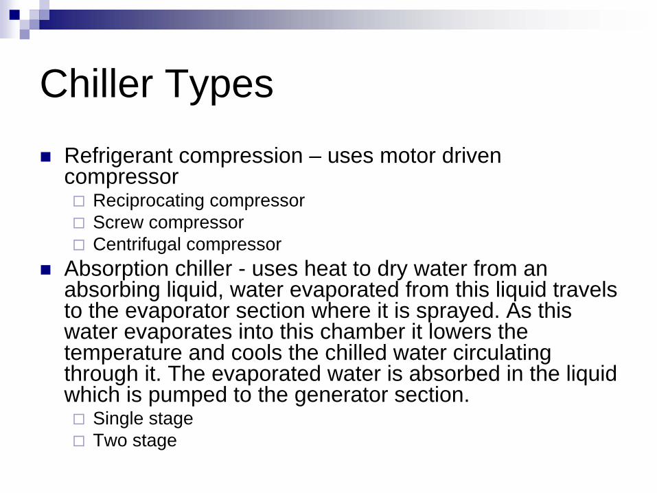
Chiller TypesRefrigerant compression – uses motor driven compressor
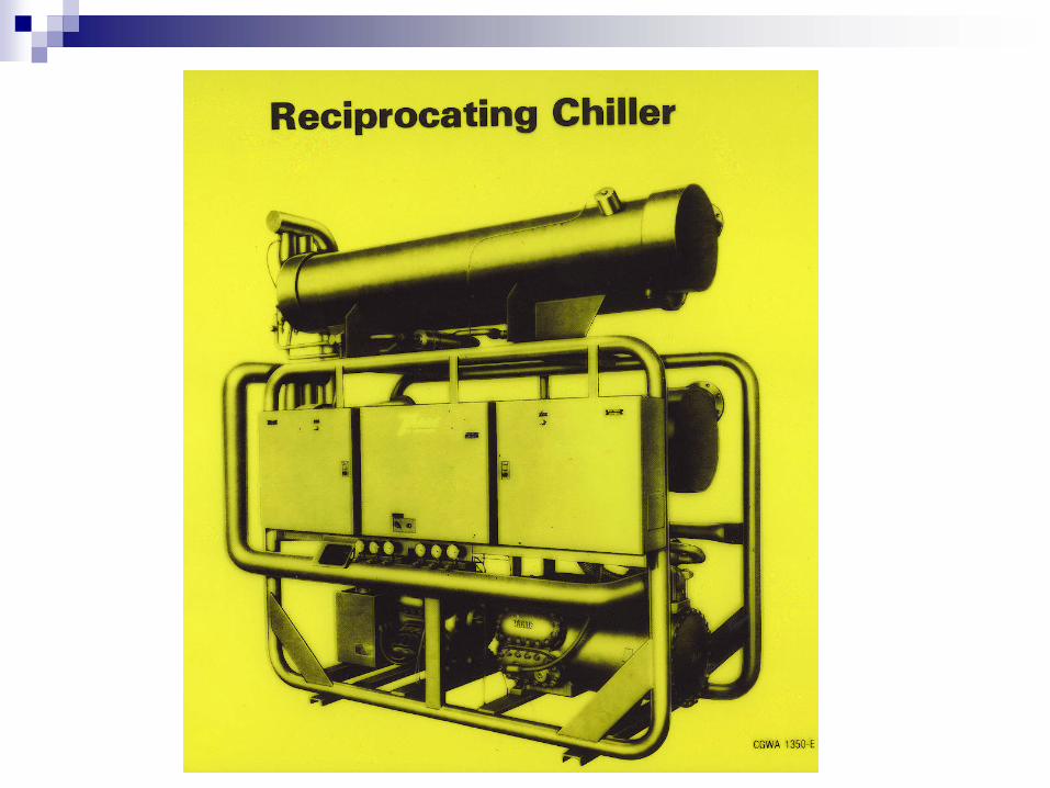
Reciprocating compressorScrew compressorCentrifugal compressor
Absorption chiller - uses heat to dry water from an absorbing liquid, water evaporated from this liquid travels to the evaporator section where it is sprayed. As this water evaporates into this chamber it lowers the temperature and cools the chilled water circulating through it. The evaporated water is absorbed in the liquid which is pumped to the generator section.
Single stageTwo stage


Steam Absorption Chiller

Cooling Towers
Condenser water pumped to cooling tower Cooling related to air humidityEvaporative cooling process where water temperature reducedWater should be treated for algae control Water blow-down to control dissolved solids

Cross Draft Cooling Tower

Counter Flow Cooling Tower

Typical Operating Parameters
Chiller output - 45 F water, Return water 10 F to 20 F warmerCondenser water – 85 F in, 95 F outEnergy Use
Electrical = .6 to .8 kWh/ton (average is $0.08/ton-hr @ $0.12/kWh)Absorption = 18 MBH/ton single stage ($.22/ton-hr @ $12/million Btu), 12 MBH two stage ($0.14/ton-hr @ $12/million Btu)

Design Considerations
Degree of humidity control and other issues that affect supply chilled water temperatures.Electrical demand costsSystems served
Constant or variable flowSeasonal & peak requirements
Outside temperature and humidity Cooling tower location
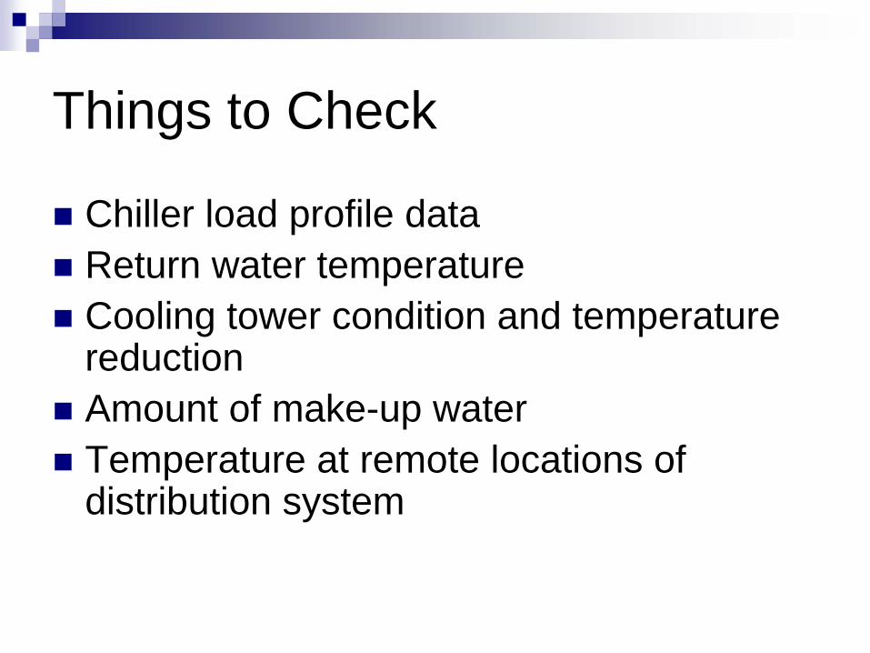
Things to Check
Chiller load profile dataReturn water temperatureCooling tower condition and temperature reductionAmount of make-up waterTemperature at remote locations of distribution system
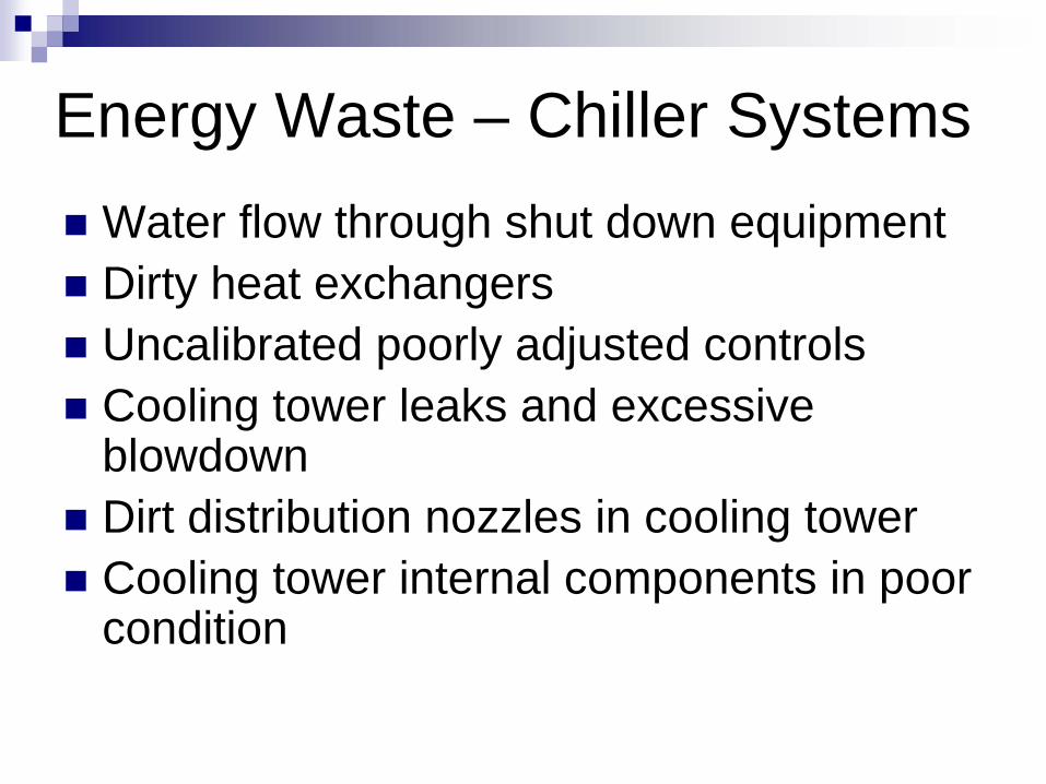
Energy Waste – Chiller SystemsWater flow through shut down equipmentDirty heat exchangersUncalibrated poorly adjusted controlsCooling tower leaks and excessive blowdownDirt distribution nozzles in cooling towerCooling tower internal components in poor condition

Energy Waste – Chiller Systems
No insulation on pipes < 60 FDistribution system leaksUnbalanced flow causing excessive pressure drop through control valvesToo much bypass water in circulating systems
Energy Inefficiencies – Chiller Systems
Use of air cooled condensersUse of oversized equipmentConstant chilled water temperatureConstant condenser water temperatureBlowdown from tower basin

Energy Inefficiencies – Chiller Systems
No duct at fan discharge for velocity pressure recoveryNo adjustment of fan blades for load or season High pressure pumps instead of booster pump useVariable flows with constant speed pumps

ECM – Raise Chilled Water Temperature
Raising the leaving chilled water temperature increases the performance efficiency Could be combined with DOAS units having DX coolingLowers distribution energy losses

ECM – Lower Condenser Water Temperatures
lowering the incoming condenser water temperature improves the chiller efficiencyCan vary by weather conditionsWill cause cooling tower energy to increaseCan set up chillers controls to optimize energy use of system

ECM – Isolate Off-line Chillers
During low cooling loads when only one chiller needs to operate, the system design has chilled water flowing through all chillers causing multiple pumps to operate and the dilution of the chilled water temperature.Wastes pump Hp and requires lower chilled water temperatures.Install new pipe and valves to allow individual chillers and cooling towers to operate isolated from others. New pumps may also be required.

ECM – Replace Air Cooled Condensers with Cooling Towers
Air cooled condensers normally operate at a temperature difference of 20 F higher than the outdoor temperature. Cooling towers perform at 10 F above the wet bulb temperature which can be more than 20 F lower than the dry bulb temperature. The result the chiller’s condensing temperature could be more than 15 F lower with a cooling tower which has a dramatic effect on chiller performance.

ECM – Thermal Storage Systems
Best done during addition to central chilled water system Cost of storage tank less than new chillersReduces electrical demand chargesCan be chilled water or ice storage

Thermal Storage – Optimizing Chillers

Pumps
Rotating impeller in housing causes water flowFlow rates changed by
Changing pumpsShaving impellerUsing variable speed motor
Placement important – need some water pressure on pump for proper operation

Pumping Energy Waste
Use of excessive valving to balance flowFailure to adjust pump for correct flow during system balance – pumps larger than 10 Hp Failure to use booster pumps when a portion of distribution systems requires an 20 % increase in pressure

ECM – Utilize Variable Flow Distribution
Requires two way valves at point of use May require primary/secondary pumping system since chillers have a low limit for flow.Achieves savings in pumping horsepowerUtilizes full temperature rise of system design

Electrical Distribution
ComponentsTransformersHigh voltage switch gearPower distribution linesMotors

Electrical Distribution
Design ConsiderationsBuilding/Area electrical loads Length of distributionEquipment voltage requirementsNeed for back-up power

Things to Check
Change in building function since transformer selectionUse of standard or high efficiency motorsCharge for poor power factor by electrical utility company

Energy Waste - Electrical Distribution
Oversized transformersEnergized transformers in unused buildingsTransformer taps not set at proper setting

Energy Inefficiency - Electrical Distribution
Power factor less than 85%Use of non premium efficiency motors

ECM – Replace Lightly Loaded Transformers
Electrical transformers are up to 98 % efficient and thus there are losses in electrical energy even when the equipment being served is switched off. Lightly loaded transformers should be replaced with an high efficient one that is sized for the current load. Select the transformer with the lowest temperature rating

ECM – Power Factor Correction
Poor power factor increases losses in the electrical distribution lines, transformers and motors It is caused by lightly loaded and inefficient motorsInstall properly sized motorsControl power factor by placing capacitors before problem equipment

ECM – Utilize Premium Efficiency Motors vs. Standard Efficiency Motors
Comparison with standard efficiency motors with replacement upon failureElectrical cost = $0.055/kWh
Motor SizeExisting
Efficiency (%)Proposed
Efficiency (%)Energy Saved
(kWh/yr)Energy Cost
Savings ($/yr)Total Cost
Premium ($)
Additional Cost of New
Motor vs. Rewinding
Simple Payback (yrs)
25 88.00% 93.60% 9,149 $503 $1,115 $558 1.1
20 87.50% 93.60% 7,973 $438 $985 $493 1.1
15 86.00% 93.00% 6,862 $377 $790 $395 1.0
10 85.00% 91.70% 4,378 $241 $590 $295 1.2
7.5 84.00% 91.00% 3,431 $189 $486 $243 1.3
5 82.00% 89.50% 2,451 $135 $356 $178 1.3
3 80.00% 89.50% 1,862 $102 $269 $135 1.3
2 77.00% 86.50% 1,242 $68 $274 $137 2.0
1 73.00% 85.50% 817 $45 $213 $107 2.4

ECM – Utilize Premium Efficiency Motors vs. High Efficiency Motors
Comparison with post 1997 high efficiency motors with replacement upon failureElectrical cost = $0.055/kWh
Motor SizeExisting
Efficiency (%)Proposed
Efficiency (%)Energy Saved
(kWh/yr)Energy Cost
Savings ($/yr)Total Cost
Premium ($)
Additional Cost of New Motor vs. Rewinding Simple
Payback (yrs)
25 91.70% 93.60% 3,104 $171 $1,115 $558 3.3
20 91.00% 93.60% 3,398 $187 $985 $493 2.6
15 91.00% 93.00% 1,960 $108 $790 $395 3.7
10 89.50% 91.70% 1,438 $79 $590 $295 3.7
7.5 88.50% 91.00% 1,225 $67 $486 $243 3.6
5 87.50% 89.50% 653 $36 $356 $178 5.0
3 86.50% 89.70% 627 $35 $269 $135 3.9
2 84.00% 86.50% 327 $18 $274 $137 7.6
1 82.50% 85.50% 196 $11 $213 $107 9.9

ECM – Install EMCS
Central control and optimization of HVAC systemsRemote monitoring and evaluation of system performanceMaintenance aid and problem anticipationElectrical demand monitoring and controlNeed to actively use and adopt as a tool for full benefits

ECM - Replace Lightly Loaded Motors
Look for systems that have had loads reducedReduced loads on motors result in poor power factors and inefficienciesMeasure motor amps and compare to full load current on nameplateReplace motors loaded less than 60% of rating

Thank You
Questions?