CHILLER MANUAL - speedchiller.co.kr · with heavy machine under the instruction of safety control...
17
CHILLER MANUAL SAM JUNG ENC CO.,LTD. http:/www.speedchiller.com E-Mail: [email protected] TEL: 02)2686-3315~6 / 02)2686-3658 FAX: TEL02)2686-3317 756-1, Kwarim-dong, shiheung-city, Kyeong-ki 429-120, Korea
Transcript of CHILLER MANUAL - speedchiller.co.kr · with heavy machine under the instruction of safety control...

CHILLER MANUAL
SAM JUNG ENC CO.,LTD.http:/www.speedchiller.comE-Mail: [email protected]
TEL: 02)2686-3315~6 / 02)2686-3658 FAX: TEL02)2686-3317
756-1, Kwarim-dong, shiheung-city, Kyeong-ki
429-120, Korea

1. Cautions for conveying chiller
2. Cautions for installing chiller.
1)
In principle, chiller shall be conveyed, loaded or unloaded by heavy machine (forklift).
※
It is possible to load and unload by crane, hoist, etc, but it is required to be careful of convey, because there is no eye bolt on the outer casing face.
2) Grasping the distance to destination, required time and road condition, it is essential to firmly and securely fix the chiller before departure so that bolt may not be loosened or inside of chiller may not be damaged by vibration of vehicle for long time
transportation.
※
Waterproof measure is indispensable to protect chiller from rain or wind.
3) After arriving at the destination, be sure to visually check the possible problem that may occur while conveying chiller. Then, convey it to the installing place
with heavy machine under the instruction of safety control section.
※
However, when moving chiller into the building, be sure to use conveying cart instead of pipe or lever.
1) Install chiller in the building (If installing outdoors, be sure to install shade or rainwater cover.)
2) Install chiller at place free of dust, moist and foreign materials.
3) Install chiller at well ventilated place without heater.
4) Install chiller at place where it can be easily checked and repaired.
5) Connect pipe after checking inlet and outlet of cold water.
6) Install the power switch separate from other machines.
7) Check visually whether supporter or hanger of pipe is installed correctly.
8) Check visually or by drawing the pipe joint and inlet/outlet of connection of the other service.
9) Check the capacity of the 1st
electric distributing panel (power).
10) While constructing electric cable, be sure to check insulation (earth).
1) The 1st
power supply of chiller and power breaker inside chiller shall be on always and they may be off in emergency only.
2) As system runs to prevent rupture by freezing all the year round, power supply shall be on always.
3. Cautions for use

How to operate CHILLER CONTROLLER
1) Name of each part
①
: LCD screen (128 * 64 DOT) BLUE COLOR ②
: Run/Stop switch (Run/Stop is repeated each time switch is pressed.)③
: Buzzer/Stop switch (switch that stops buzzer which operates in the case of error)④
: Moving switch (switch to move set value or set menu)⑤
: Decreasing switch (switch to decrease set value)⑥
: Setting switch (switch to convert main screen into set screen)⑦
: Increasing switch (switch to increase set value)⑧
: Run LED (While running, green LED is lit.)⑨
: Stop LED (While stopping, red LED is lit.)⑩
: Warning LED (In the case of error, red LED flickers.)

2) Initial screen
3) Normal operating screen
①
②
③ ④
⑤
⑥
⑦
Initial screen when chiller is powered for the first time.(all operations in halt)
Normal operating state after supplying power and manipulating running key.
①
: Indicating the state of operating condenser fan
Condenser fan in rotation
②
: Indicating water level
High water level (water supplying SV output halts)
Low water level (water supplying SV output in operation)

③
: Indicating pump output state
Pump in normal operation
Pump in halt
④
: Indicating comp output state
general control:Comp in normal operation
Comp in halt
precise control: Comp operates always.
Heating SV in operation
Chilling SV in operation
Both operating and chilling SV in operation
⑤
: Indicating the electric current value of main power supply at present
⑥
: Indicating the set temperature of cooling water
⑦
: Indicating the temperature of cooling water at present
4) OFF Screen
Only pump and comp halt.Condenser fan and water supplying SV normally operate per input signal.

5) Setting temperature of cooling water (0~ 70)
6) Deviation of main temperature ( ±0.0
~ ±9.9)
EX) Example of useIf deviation of main temperature is ±0.5’C and set temperature is 10.0’C, comp runs at 10.5’C and stops at 9.5’C in normal control.
7) Adjusting main temperature (-9.9
~ +9.9)
Press setting key for 5 seconds. Press setting key.
Wait for 5 seconds without pressing any key. Use increasing, decreasing or
moving key to alter set value.Set value is saved automatically.
Press setting key for 5 seconds.
Press moving key once.
Press setting key.
Press setting key.
Press setting key or wait for 5 seconds.
Use increasing, decreasing or moving key to alter set value.
Wait for 5 seconds (automatic saving).
Use increasing, decreasing or moving key to alter set value.
The set value is to adjust deviation between current indicated temperature of cooling water and actual temperature of cooling water.
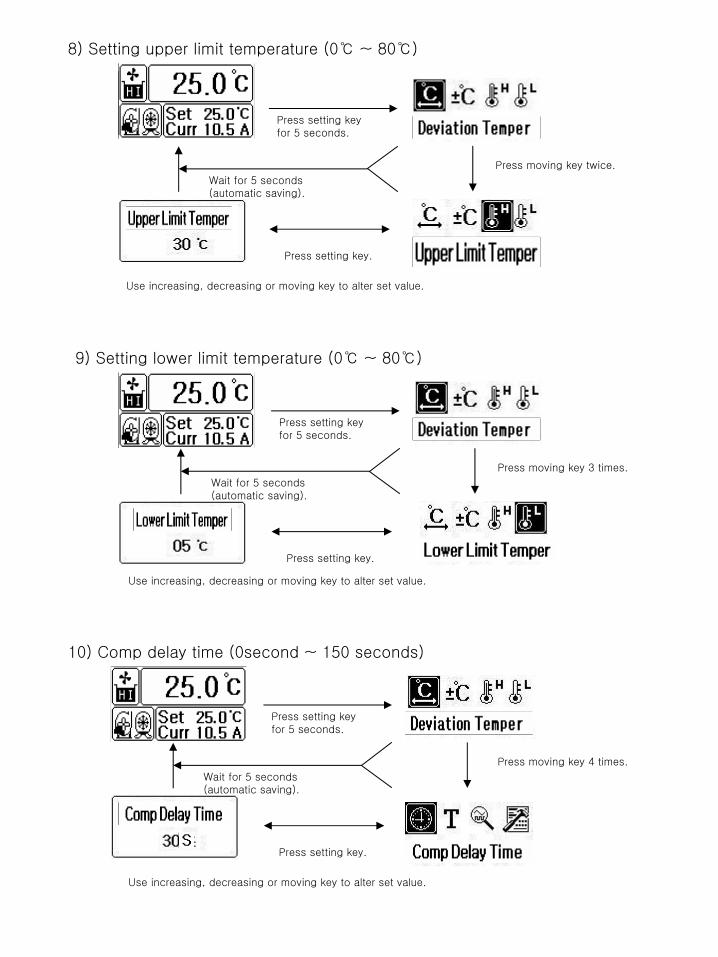
8) Setting upper limit temperature (0
~ 80)
Press setting key for 5 seconds.
Press moving key twice.
Press setting key.
Wait for 5 seconds (automatic saving).
Use increasing, decreasing or moving key to alter set value.
9) Setting lower limit temperature (0
~ 80)
Press setting key for 5 seconds.
Press moving key 3 times.
Press setting key.
Wait for 5 seconds (automatic saving).
Use increasing, decreasing or moving key to alter set value.
10) Comp delay time (0second ~ 150 seconds)
Press setting key for 5 seconds.
Press setting key.
Wait for 5 seconds (automatic saving).
Use increasing, decreasing or moving key to alter set value.
Press moving key 4 times.

11) Trip time (0 second ~ 10 seconds)
Press setting key for 5 seconds.
Press setting key.
Wait for 5 seconds (automatic saving).
Use increasing, decreasing or moving key to alter set value.
Press moving key 5 times.
12) Comp controlling method (general control, precise control)
Press setting key for 5 seconds.
Press setting key.
Wait for 5 seconds (automatic saving).
Use increasing, decreasing key to alter control method.
Press moving key 6 times.
13) Details of problem (recording up to 10 items)
Press setting key for 5 seconds.
Press setting key.
Wait for 5 seconds (automatic saving).
Use moving key to move the screen of details of problem.
Press moving key 7 times.

14) Adjusting current ( -9.9A ~ 9.9A)
Press setting key for 5 seconds.
Press setting key.
Wait for 5 seconds (automatic saving).
Use increasing, decreasing or moving key to alter set value.
Press moving key 8 times.
15) Remote control (general control, remote control)
Press setting keyfor 5 seconds.
Press setting key.
Wait for 5 seconds (automatic saving).
Use increasing, decreasing key to alter control method.
Press moving key 9 times.
16) Valve delay time (1 second ~ 60 seconds)
Press setting key for 5 seconds.
Press setting key.
Wait for 5 seconds (automatic saving).
Use increasing, decreasing or moving key to alter set value.
Press moving key 10 times.

17) Preventing rupture caused by freezing (0
~ 70)
Press setting key for 5 seconds.
Press setting key.
Wait for 5 seconds (automatic saving).
Use increasing, decreasing or moving key to alter set value.
Press moving key 11 times.
No Name Setting range Basic set value Remark
1 Set temp Low temperature ~high temp 10
2 Temperature dev ±0.0
~ ±9.9 ±1.0
3Temperature adjustment
-9.9 ~ +9.9 0.0
4Upper
temperature0
~ +80 70
5Lower
temperature0
~ +80 8
6 Comp delay 0 second~150 seconds 10 seconds
7 Trip time 0 second~10 seconds 5 seconds
8Comp control
methodGeneral control/precise
controlgeneral
control
9Current
adjustment-9.9A ~ +9.9A 0.0A
10 Remote controlRemote control/general
controlgeneral
control
11 Valve delay 1 second~ 60 seconds 2 seconds
12Preventing
rupture caused by freezing
0
~ 70 5

Output specification
PCB No WIRE No Output name Output condition
R R1 AC220V input (R-
Phase)
T T1 AC220V input (T-
Phase)
CM T1 AC220Voutput(T-
Phase)
A SJ1 Preliminary
B SJ2 Solenoid Valve output
When low signal enters Solenoid Valve input
C SJ3 ALARM output When alarm sounds
D SJ4 Water supplying SV When low water level is detected
E SJ5 Heating SV When lower than set temperature in precise control
F SJ6 Cooling SV Always ON in general control
When higher than set temperature in precise control
G SJ7 PUMP MG When power is ON
H SJ8 COMP MG When higher than (set temperature+ temperature deviation) in general control
Always ON in precise control
I SJ9 FAN MG When low signal enters FAN control input

Input specification
PCB No WIRE No Input name Input condition
CM SJ- AC14.5V common input
1 SJ10 Low level input NC
2 SJ11 High level input NC( Solenoid Valve output when it opened)
3 SJ12 Pump OCR NC
4 SJ13 Comp OCR NC
5 SJ14 FAN OCR NC
6 SJ15 High pressure input NC
7 SJ16 Low pressure input NC
8 SJ17 FAN control NC(FAN OCR output while opening)
9 SJ18 FLOW switch input NO(to
be closed within 15 seconds while water is circulating)
10 SJ19 remote contact point NC(remote
control operates when it is opened while remote control is selected)
11 SJ20 Solenoid Valve input NC(AC220V being applied 2 seconds after it opened)
SJ21, SJ21 CT sensor input1 Solenoid Valve
SJ22, SJ22 CT sensor input2
R1 Reversed Phase input R
S1 Reversed Phase input S
T1 Reversed Phase input T

Troubleshooting (Measures to be taken when alarm sounds)
Alarm Measure Remark
Compressor overload
Reset magnet OCR!! If repeated in 3 times, replace it!! automatic restoration
Pump overload Reset magnet OCR!! If repeated in 3 times, replace it!! automatic restoration
Abnormality in low level
Provide a Directly-supplied water valve, and refill cooling water by manual.
automatic restoration
High pressure alarm
Check condenser fan motor and ventilation around condenser.
automatic restoration
Low pressure alarm
Check cold water circulation system, supply refrigerant R-22
automatic restoration
Abnormal main temperature sensor
Check PT100Ω
temperature sensor. automatic restoration
High temperature alarm
Check present temperature and equipment under load, check temperature sensor
automatic restoration
Low temperature alarm
Check quantity of circulating cold water and level in the water tank, check temperature sensor
automatic restoration
Alarm of water circulation
Check valve lock and the part under load, check floor sensor.
manual restoration
Reversed Phase error
Replace RST of main power line by RTS. manual restoration
Condenser fan overload
Reset magnet OCR!! If repeated in 3 times, replace it!! automatic restoration

T CM A B CR E F G H ID CM 1 2 3 4 5 6 7 8 9 1011 CACACBCB
T S Rb2 B2 A2 b1 B1 A1
MONITORCONNECTOR
Wiring diagram
Output
R : AC220V input (R1)T : AC220V input(T1)CM : Common output (T1)A : spare (SJ1)B : solenoid valve
output (SJ2)C : ALARM output (SJ3)D : Water supplying SV(SJ4)E : Heating SV(SJ5)F : Cooling SV(SJ6)G : PUMP MG(SJ7)H : COMP MG(SJ8)I : FAN MG(SJ9)
Input
CM : Common input (SJ-)1
: Low level input (SJ10)2
: High level input (SJ11)3 :
Pump OCR(SJ12)4
: Comp OCR(SJ13)5
: FAN OCR(SJ14)6
: High pressure input (SJ15)7
: Low pressure input (SJ16)8
: FAN control (SJ17) 9
: FLOW switch point (SJ18)10
: Remote point (SJ19)11
: Solenoid Valve input (SJ20)
CT Sensor input
CA : CT sensor input A(SJ21, SJ21)
CB : CT sensor input B(SJ22, SJ22)
Reversed Phase inspection3Phases consist ofR : R-Phase(R1) S : S-Phase(S1)T : T-Phase(T1)
PT100 temperature sensor input
A1B1b1: PT100 sensor1
A2B2b2: PT100 sensor2

1.Maintenance of PUMP
(1) PUMP: As device for heat movement of fluid, it aims to transmit regular pressure and fluid
quantity through pipe to the part where heat of fluid must be changed. It is composed of excessive current C/T and operation of E.O.C.R.
1) Symptom : Alarm on the APC-21 L.C.D monitor.
2) Cause for alarm ①
Alarm for excessive current C/T
②
Alarm for current detection by pump motor magnet E.O.C.R.
3) Countermeasure
①
Operate it again after altering set value in the menu of setting unit numerical value.
②
Replace pump motor if burned and damaged.
4) Maintenance
overhead
Exit of cool water
motor impeller pump
Entrance of cool water
Insertion of foreignSubstances and breakage

2. Maintenance of COMPRESSOR
(2) COMP : As GAS-compressed (piston) MOTOR COMPRESSOR that makes refrigerant GAS
by electric machine heat, it is composed of refrigerant, high pressure, low temperature and switch operation.
1) Symptom: Alarm on the APC-21 L.C.D monitor
2) Cause for alarm
①
Alarm for excessive current C/T
②
Alarm for current detection by compressor motor magnet E.O.C.R.
③
Alarm for set value of high pressure and low pressure of refrigerant gas
3) Countermeasures ①
Operate it again after altering set value in the menu of setting unit alarm numerical value
②
Replace compressor motor coil if burned and damaged.
③
When high pressure and low pressure switch is operating, high pressure : cleaning condenser/ low pressure: supply refrigerant.
4) Maintenance
Suction pipe Discharge pipe
comp
R-22 regrigerant

3. Maintenance of FAN
(1) FAN : Discharging the heat of high temperature and high pressure gas that is produced when compressing freezing gas by propeller angle and motor rotation, it is composed of excessive current C/T and E.O.C.R operation
1) Symptom : Alarm on the APC-21 L.C.D monitor 2) Cause for alarm
①
Cause for excessive current C/T
②
Alarm for current detection by fan motor magnet E.O.C.R. 3) Countermeasure
①
Operate it again after altering set value in the menu of setting unit alarm numerical value
②
Replace fan motor coil if burned and damaged.
4) Maintenance
Protection grid
Electric control box
condenser