Chief Engineer, Systems
17
GRID Chief Engineer, Systems March 2011 HVDC Grids: A View to Standardisation Carl Barker
-
Upload
wade-finch -
Category
Documents
-
view
60 -
download
0
description
HVDC Grids: A View to Standardisation. Carl Barker. Chief Engineer, Systems. March 2011. Why DC Transmission?. Page 3. What are DC Grids?. Page 6. How will DC Grids Evolve?. Page 11. DC Grid Standardisation. Page 13. Agenda. Charges and Discharges Every Half Cycle. AC. DC. - PowerPoint PPT Presentation
Transcript of Chief Engineer, Systems

GRID
Chief Engineer, SystemsMarch 2011
HVDC Grids:
A View to StandardisationCarl Barker

HVDC Grids: A View to Standardisation – March 2011 - P 2
Agenda
Why DC Transmission? Page 3
What are DC Grids? Page 6
How will DC Grids Evolve? Page 11
DC Grid Standardisation Page 13

HVDC Grids: A View to Standardisation – March 2011 - P 3
Why DC Transmission?
HVDC transmission is the correct technology for bulk submarine energy transfer.
AC
DC
Charges and DischargesEvery Half Cycle
Only Charges the Cable Once

HVDC Grids: A View to Standardisation – March 2011 - P 4
Why DC Transmission?
Basic Structure of VSC Transmission System
t
Idc
t
ii
Iact
i
Iac
Idc= V1- V2R
DC transmissionline
Q1 Q2P
VSC VSC
Station 1 Station 2
V1 V2
IC1
Network1
Network2

HVDC Grids: A View to Standardisation – March 2011 - P 5
Agenda
Why DC Transmission? Page 3
What are DC Grids? Page 6
How will DC Grids Evolve? Page 11
DC Grid Standardisation Page 13

HVDC Grids: A View to Standardisation – March 2011 - P 6
What are “DC Grids”?
• “DC Grids” – Multiple converters connecting AC power networks to a DC power network
• “DC Grids” – Permit the economic transfer of power over buried cables reducing environmental impact
• “DC Grids” – Permits economic bulk transfer over large distances
• “DC Grids” – Reduce the number of AC/DC Conversions therefore reduce losses
HVDC Grids: A View to Standardisation – March 2011 - P 7
132kV
400V400V400V
11kV11kV
400V400V400V
11kV11kV
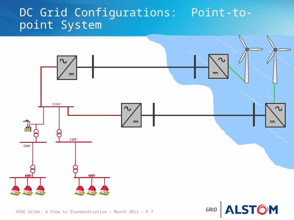
DC Grid Configurations: Point-to-point System

HVDC Grids: A View to Standardisation – March 2011 - P 8
132kV
400V400V400V
11kV11kV
400V400V400V
11kV11kV
DC Grid Configurations: Radial System

HVDC Grids: A View to Standardisation – March 2011 - P 9
132kV
400V400V400V
11kV11kV
400V400V400V
11kV11kV
DC Grid Configurations: Meshed System
HVDC Grids: A View to Standardisation – March 2011 - P 10
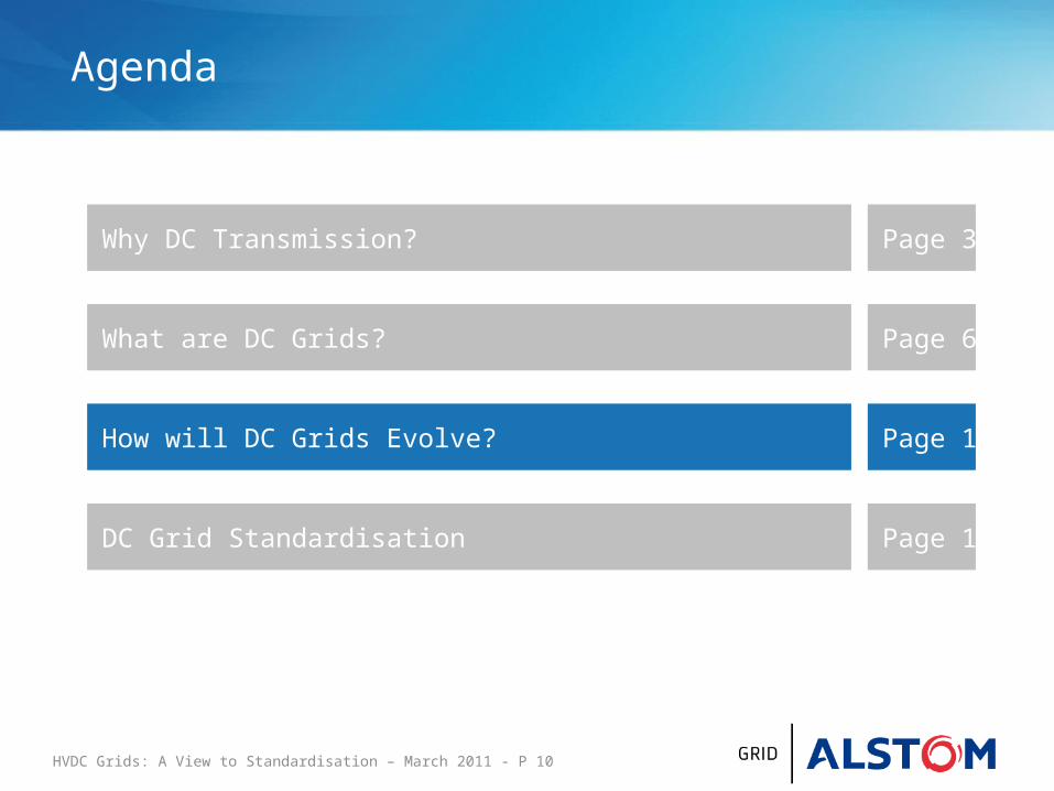
Agenda
Why DC Transmission? Page 3
What are DC Grids? Page 6
How will DC Grids Evolve? Page 11
DC Grid Standardisation Page 13

HVDC Grids: A View to Standardisation – March 2011 - P 11
How will DC Grids Evolve?
• Large pan-European grids− Strategic all encompassing planning at the outset
• Four, five, six terminal grids− Small independent DC grids developing ‘organically’
“DC Grids” require rules in the same way that AC grids operate within “AC Grid Codes”
HVDC Grids: A View to Standardisation – March 2011 - P 12
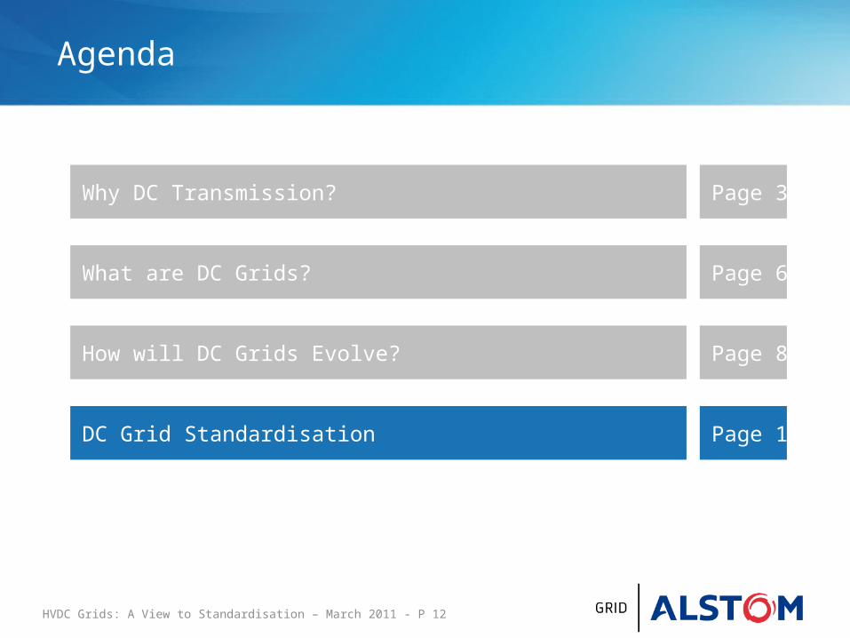
Agenda
Why DC Transmission? Page 3
What are DC Grids? Page 6
How will DC Grids Evolve? Page 8
DC Grid Standardisation Page 13
HVDC Grids: A View to Standardisation – March 2011 - P 13
Do We Need to Standardise?
Purpose of Standards
− Reduce costs (design one build many, long run cost reductions etc.)
− Improve asset availability through improved maintainability
(common or interchangeable spares, common tooling etc.)− Support interoperability− Allowing interconnected systems to be built incrementally
and by different equipment suppliers, thus support
incremental investment plans and avoid “stranded assets”− Allow separation of cable and converter procurement thus
allowing buyers to take advantage of the increasing
number of HVDC cable manufacturers

HVDC Grids: A View to Standardisation – March 2011 - P 14
Functional Specifications
• AC/DC Converters
• HVDC Cables
• DC Breakers
• DC-DC Converters
• Dump Resistor
Equipment that should have a common functional specification

HVDC Grids: A View to Standardisation – March 2011 - P 15
Design Specification
• Topology?− Symmetric Monopole− Monopole− Bipole
• DC Voltage (nominal, steady-state and transient range)
• Fault Current Contribution
• Multi-terminal DC Protection
• Multi-terminal DC control*
*Barker CD, Whitehouse RS, ‘AUTONOMOUS CONVERTER CONTROL IN A MULTI-TERMINAL HVDC SYSTEM’, IET, ACDC 2010
Equipment that should be defined at the initial design stage

HVDC Grids: A View to Standardisation – March 2011 - P 16
DC Grid Standardisation Activities
• International recommendations being created;− CENELEC - Four, five, six terminal grids− Cigrè B4-52 - Large pan-European grids
• Cigrè have just approved five further DC grid working groups;− B4-56 Guidelines for the preparation of “connection agreements” or
“Grid Codes” for HVDC grids
− B4-57 Guide for the development of models for HVDC converters in a HVDC grid
− B4-58 Devices for load flow control and methodologies for direct voltage control in a meshed HVDC Grid
− B4-59 Devices for load flow control and methodologies for direct voltage control in a meshed HVDC Grid
− B4-60 Designing HVDC Grids for Optimal Reliability and Availability performance

www.alstom.com