Chicago - images.atgstores.com · conductor of a fan identified as grounded ... Chicago TM 3....
14
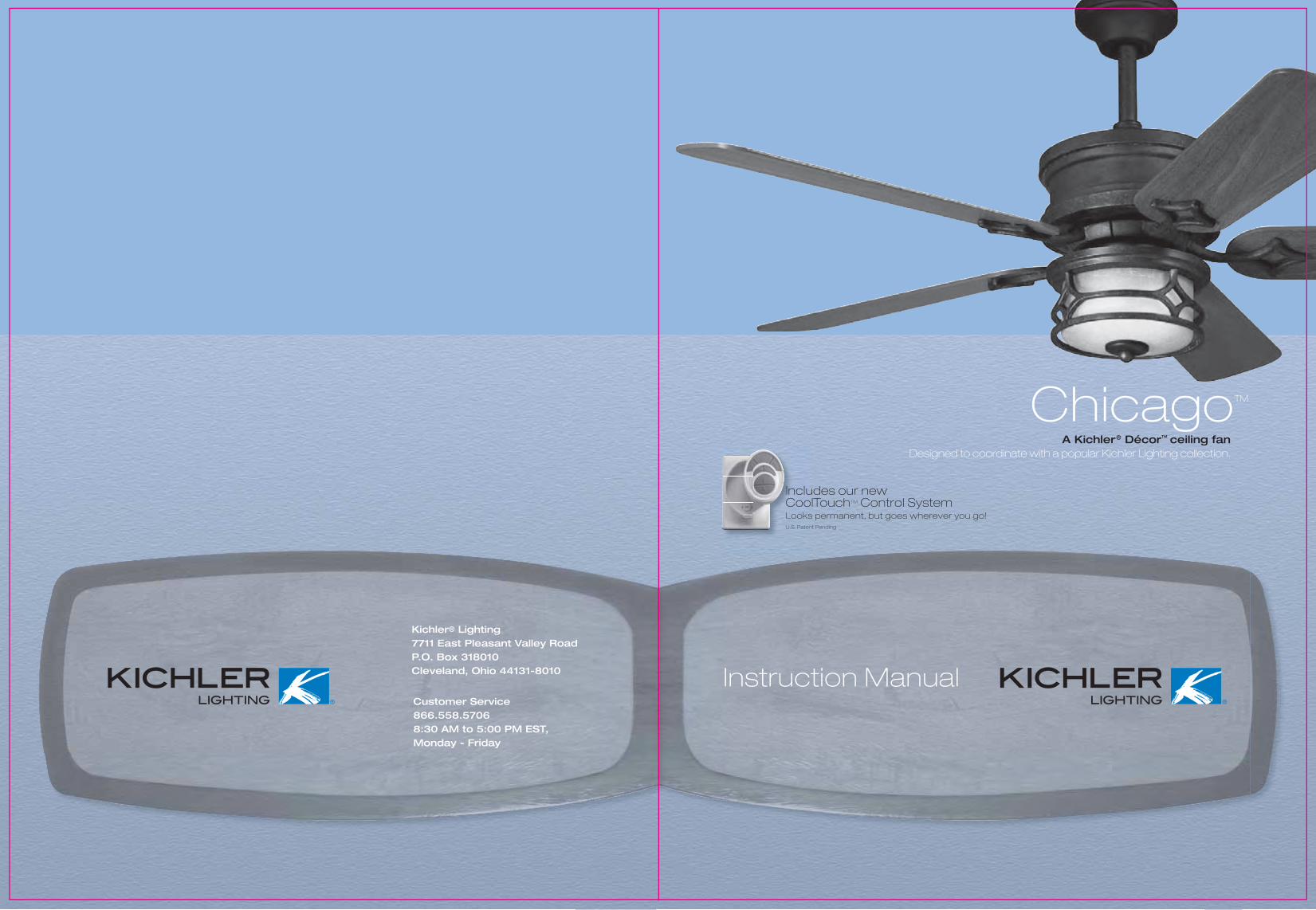
Chicago TM Includes our new CoolTouch TM Control System Looks permanent, but goes wherever you go! U.S. Patent Pending Kichler ® Lighting 7711 East Pleasant Valley Road P.O. Box 318010 Cleveland, Ohio 44131-8010 Customer Service 866.558.5706 8:30 AM to 5:00 PM EST, Monday - Friday A Kichler ® Décor ™ ceiling fan Designed to coordinate with a popular Kichler Lighting collection. Instruction Manual
Transcript of Chicago - images.atgstores.com · conductor of a fan identified as grounded ... Chicago TM 3....
ChicagoTM
Includes our newCoolTouchTM Control SystemLooks permanent, but goes wherever you go!U.S. Patent Pending
Kichler® Lighting 7711 East Pleasant Valley Road P.O. Box 318010 Cleveland, Ohio 44131-8010
Customer Service 866.558.5706 8:30 AM to 5:00 PM EST,Monday - Friday
A Kichler® Décor™ ceiling fanDesigned to coordinate with a popular Kichler Lighting collection.
Instruction Manual
1. To reduce the risk of electric shock, insure electricity has been turned off at the circuit
2.
3. WARNING: To reduce the risk of electrical
4.
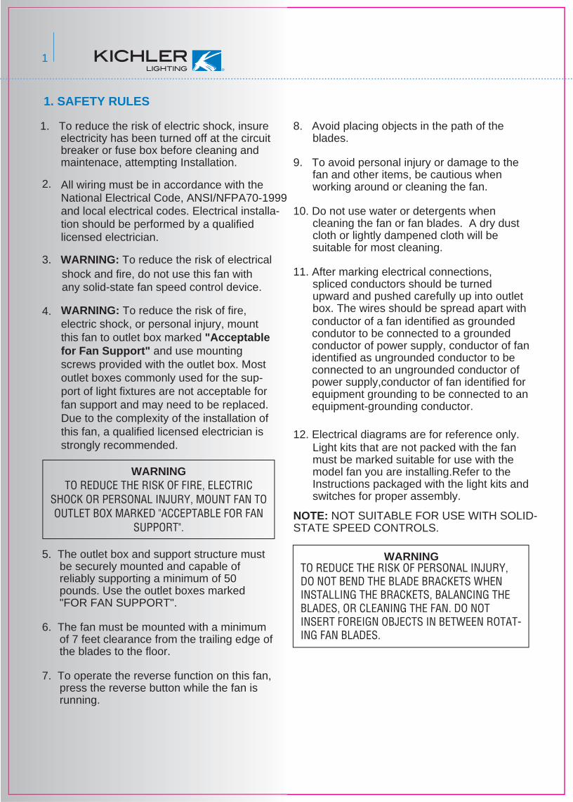
5. The outlet box and support structure must be securely mounted and capable of reliably supporting a minimum of 50 pounds. Use the outlet boxes marked "FOR FAN SUPPORT".
6. The fan must be mounted with a minimum of 7 feet clearance from the trailing edge of the blades to the floor.
7. To operate the reverse function on this fan, press the reverse button while the fan is running.
8. Avoid placing objects in the path of the blades.
9. To avoid personal injury or damage to the fan and other items, be cautious when working around or cleaning the fan.
10. Do not use water or detergents when cleaning the fan or fan blades. A dry dust cloth or lightly dampened cloth will be suitable for most cleaning.
11. After marking electrical connections, spliced conductors should be turned upward and pushed carefully up into outlet box. The wires should be spread apart with
12. Electrical diagrams are for reference only. Light kits that are not packed with the fan must be marked suitable for use with themodel fan you are installing.Refer to the Instructions packaged with the light kits and switches for proper assembly.
NOTE: NOT SUITABLE FOR USE WITH SOLID-STATE SPEED CONTROLS.
1. SAFETY RULES
WARNINGTO REDUCE THE RISK OF FIRE, ELECTRIC
SHOCK OR PERSONAL INJURY, MOUNT FAN TO OUTLET BOX MARKED "ACCEPTABLE FOR FAN
SUPPORT".
WARNING
1
All wiring must be in accordance with the National Electrical Code, ANSI/NFPA70-1999 and local electrical codes. Electrical installa-tion should be performed by a qualified licensed electrician.
WARNING: To reduce the risk of fire, electric shock, or personal injury, mount this fan to outlet box marked "Acceptable for Fan Support" and use mounting screws provided with the outlet box. Most outlet boxes commonly used for the sup-port of light fixtures are not acceptable for fan support and may need to be replaced. Due to the complexity of the installation of this fan, a qualified licensed electrician is strongly recommended.
conductor of a fan identified as groundedcondutor to be connected to a groundedconductor of power supply, conductor of fan identified as ungrounded conductor to beconnected to an ungrounded conductor ofpower supply,conductor of fan identified forequipment grounding to be connected to an equipment-grounding conductor.
breaker or fuse box before cleaning and maintenace, attempting Installation.
shock and fire, do not use this fan with any solid-state fan speed control device.
TO REDUCE THE RISK OF PERSONAL INJURY, DO NOT BEND THE BLADE BRACKETS WHEN INSTALLING THE BRACKETS, BALANCING THE BLADES, OR CLEANING THE FAN. DO NOT INSERT FOREIGN OBJECTS IN BETWEEN ROTAT-ING FAN BLADES.
2
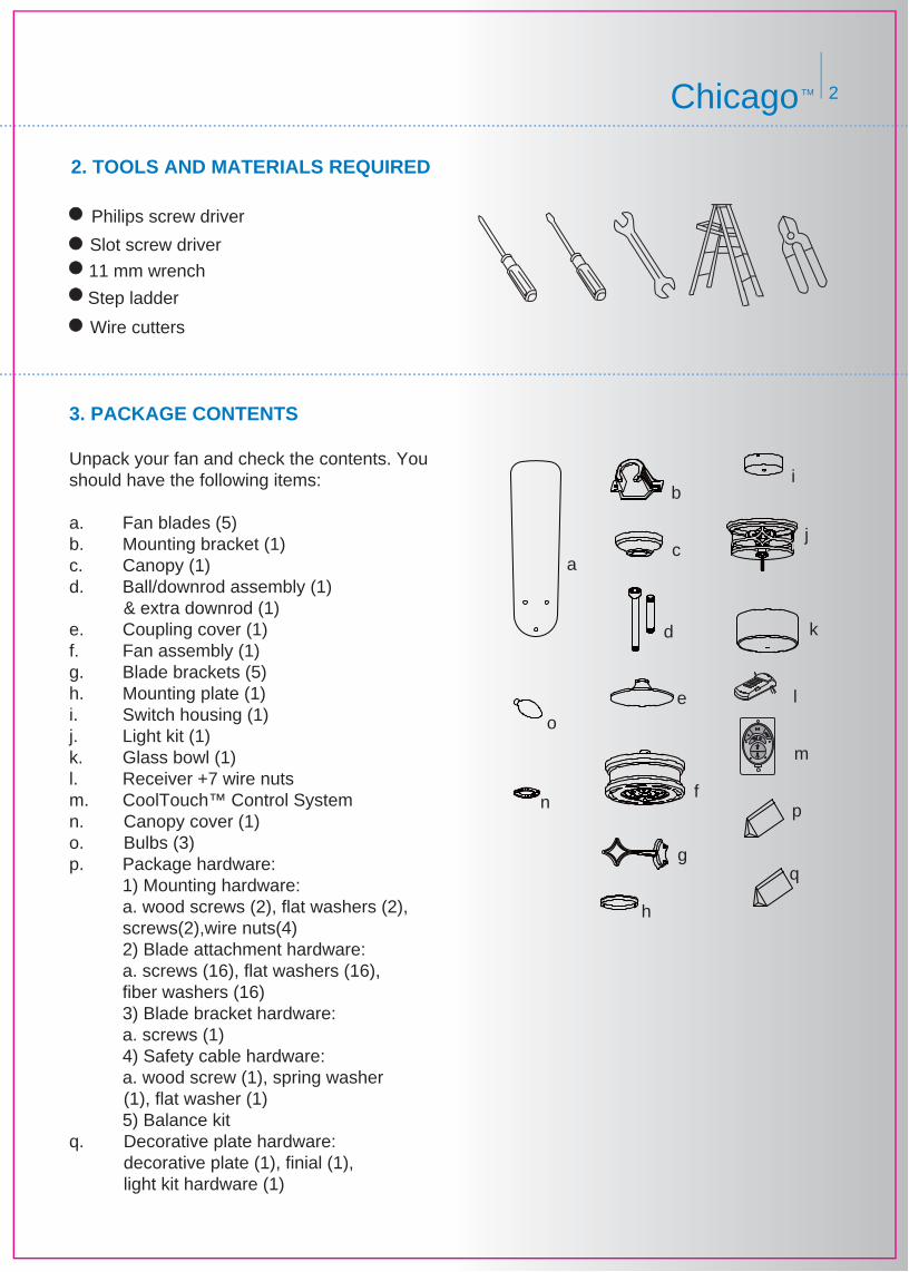
Philips screw driver
Slot screw driver
11 mm wrench
Step ladder
Wire cutters
2. TOOLS AND MATERIALS REQUIRED
ChicagoTM
3. PACKAGE CONTENTS Unpack your fan and check the contents. Youshould have the following items: a. Fan blades (5)b. Mounting bracket (1)c. Canopy (1) d. Ball/downrod assembly (1) & extra downrod (1) e. Coupling cover (1) f. Fan assembly (1) g. Blade brackets (5)h. Mounting plate (1)i. Switch housing (1)j. Light kit (1) k. Glass bowl (1)l. Receiver +7 wire nutsm. CoolTouch™ Control Systemn. Canopy cover (1)o. Bulbs (3)p. Package hardware: 1) Mounting hardware: a. wood screws (2), flat washers (2),
screws(2),wire nuts(4) 2) Blade attachment hardware: a. screws (16), flat washers (16),
fiber washers (16) 3) Blade bracket hardware: a. screws (1) 4) Safety cable hardware: a. wood screw (1), spring washer (1), flat washer (1) 5) Balance kitq. Decorative plate hardware: decorative plate (1), finial (1), light kit hardware (1)
l
m
n
o
q
i
p
h
g
f
k
j
e
d
c
b
a

3
4. MOUNTING OPTIONS
Secure the outlet box directly to the building structure. Use appropriate fasteners and building materials. The outlet box and its support must be able to fully support the moving weight of the fan (at least 50 lbs). Do not use plastic outlet boxes.
Figures 1,2 and 3 are examples of different ways to mount the outlet box.
NOTE: You may need a longer downrod to maintain proper blade clearance when installing on a steep, sloped ceiling. (Fig. 3)
To hang your fan where there is an existing fixture but no ceiling joist, you may need a joist hanging bracket as shown in Fig 4.
Outlet box
Provide strongsupport
Recessedoutlet box
Ceilingmountingplate
Outlet box
Fig. 1
Fig. 3
Fig. 4
Outlet box
Fig. 2
If there isn't an existing UL ( CUL for Canadian Installation) listed mounting box, then read the following instructions. Disconnect the power by removing fuses or turning off circuit breakers.

4ChicagoTM
Fig. 7
Fig. 5
Fig. 6
Fig. 8
Screw
shipping block
Fan assembly
Washer
120V wiresMounting screw
Electrial box
Mounting bracket
Set Screw
Cross Pin
Hanger Ball
Downrod
Downrod
Lock pin
Set screw
Hitch pin
5. HANGING THE FAN
REMEMBER to turn off the power. Follow the steps below to hang your fan properly:
Step 1. Remove the fan motor and housing assembly from the protective plastic bag and take the lower styrofoam packing pad out of the carton. Place the styrofoam pad on the floor, then place the fan assembly into the styrofoam pad with the bottom of the motor facing up. (The styrofoam pad serves as a holder for the fan during the first stages of assembly). Remove the plastic motor shipping blocks and discard. (Fig. 5)
Step 2. Secure the mounting bracket to the ceiling outlet box using screws and washers provided with the outlet box. (Fig. 6)
Step 3. Use a screwdriver to loosen the cross pin and remove it from downrod assembly. Loosen the set screw and rotate the hanger ball off the downrod. (Fig. 7)
Step 4. Loosen the two set screws and remove the hitch pin and lock pin from the motor coupling assembly. (Fig. 8)
Step 5. Carefully feed fan electrical wires up through the downrod. Thread the downrod onto the motor coupling until the hitch pin holes are aligned. Next, replace hitch pin and lock pin, and tighten both set screws. (Fig. 8)
5
Fig. 10
Registration slot
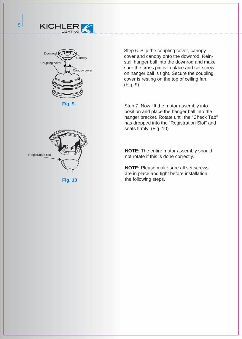
Fig. 9 Step 7. Now lift the motor assembly into position and place the hanger ball into the hanger bracket. Rotate until the “Check Tab” has dropped into the “Registration Slot” and seats firmly. (Fig. 10)
NOTE: The entire motor assembly should not rotate if this is done correctly.
NOTE: Please make sure all set screws are in place and tight before installation the following steps.
Canopy cover
DownrodCanopy
Coupling cover
Step 6. Slip the coupling cover, canopy cover and canopy onto the downrod. Rein-stall hanger ball into the downrod and make sure the cross pin is in place and set screw on hanger ball is tight. Secure the coupling cover is resting on the top of ceiling fan. (Fig. 9)

6ChicagoTM
Fig. 12
Fig. 13
Code switch
Receiver
Hangerbracket
Battery Compartment
6. INSTALLATION OF SAFETY SUPPORT( For Canadian Installation ONLY )
7. MAKE THE ELECTRIC CONNECTIONS
A safety support cable is provided to help prevent the ceiling fan from failing, please install it as follows.Step 1. Attach the provided wood screw and washers to the ceiling joist next to the mounting bracket but do not tighten. (Fig. 11-1)Step 2. Adjust the length of the safety cable to reach the screw and washers by pulling the extra cable through the cable clamp until the overall length is correct, put the end of the cable back through the cable clamp, forming a loop at the end of the cable. Tighten the cable clamp securely. Now, put the loop in the end of the safety cable over the wood screw and under the washer. Tighten the wood screw securely. See Fig. 11-2
WARNING: To avoid possible electrical shock, be sure the electricity is turned off at the main circuit breaker or fuse box before wiring.WARNING: If your house wires are different colors than referenced in this manual, stop immediately. A professional electrician is recom-mended to determine proper wiring.NOTE: The CoolTouch™ Control System is equipped with 16 code combinations to prevent possible interference from or to other remote units. The frequency switches on your receiver and transmitter have been preset at the factory. Please recheck to make sure the switches on the transmitter and receiver are set to the same position, any combination of settings will position the fan as long as each switch on the transmitter and receiver are set to the same position. (Fig. 12) Changing the order of switches on each switch block, changes the operational frequency.Step 1. Insert the receiver into the mounting bracket, with the flat toward the ceiling. (Fig. 13)Step 2. Motor to Receiver Electrical Connec-tions:NOTE: Make all of the following connections with “Wire Nut” connectors.Connect the black wire from the fan to black wire marded “TO MOTOR L” from the receiver. Con-nect the white wire from the fan to the white wire marked “TO MOTOR N” from the receiver. Connect the blue wire from the fan to the blue wire marked “For Bottom Light” from the receiver. Place a plastic wire nut on the end of the Orange Wire coming from the receiver marked “For Upper Light”. Your ceiling fan is not equipped with a Upper Light. Secure all the wire connections with the plastic wire nut provided. (Fig. 14 on the next page)
Fig. 11-2
Fig. 11-1
Ceiling
Support Brace
Outlet Box
Wood ScrewFlat Washer
Spring Washer
Wood ScrewSafety Cable Cable Clamp

7
Fig. 14
Fig. 15
Step 3. Remote Receiver to Outlet Box Electri-cal Connections: Connect the black (hot) wire from the ceiling to the black wire marked "AC in L" from the receiver. Connect the white(neutral) wire from the ceiling to the white wire marked "AC in N" from the Receiver. Secure the wire connections with the plastic wire nuts provided. (Fig. 14)
Step 4. If your outlet box has a ground wire (green or bare copper) connect it to the fan ground wires. Secure the wire connection with a plastic nut provided.
NOTE: Carefully tuck the wire connections up into the outlet box. (Fig. 14)
NOTE: The transmitting unit must be installed at a maximum distance of 30 feet from the ceiling fan for proper signal transmission between the transmitting unit and the fanʼs receiving unit.
8. INSTALLING THE CEILING CANOPY
WARNING: One last time, make sure the “Check Tab” at the bottom of the hanger bracket is prop-erly seated in the “Registration Slot” on the side of the hanger ball before attaching the canopy to the bracket. Failure to properly seat the “Check Tab” could damage the electrical wires when the ceiling fan blade direction is changed while the fan is running.
Step 1. Make sure all of the electrical connec-tions are tucked neatly into ceiling outlet box.
Step 2. Slide the canopy up to ceiling fan and onto the two screws on hanger bracket. Rotate the canopy clockwise and tighten the two screws. Next, while holding the canopy with one hand, slide the canopy cover over the screws and rotate clockwise until tight.
NOTE: You may need to adjust the canopy mounting screws as necessary until the canopy and canopy cover have a snug fit. (Fig. 15)
white (neutral)
Blue(for bottom light)
Ground wire
White("AC IN N")
Copper (ground)
White("to motor N")
Green or bare
White (neutral)
Black (motor)
Orange (For upper light)
Blue(for bottom light)
Black ("to motor L")
Receiver
Black("AC" IN L")
Black (hot)
Outlex box
Canopy cover
Canopy
Screw
Hanger bracket
Outlet box

8Chicago TM
9. ATTACHING THE FAN BLADES
Fig. 16
Fig. 17
Fig. 18
10. INSTALLATING THE MOUNTING PLATE
Step 1 Attach the blade to the blade bracket using the screws, washers and fiber washers as shown in Figure 16. Start screw into bracket. Repeat for the two remaining screws.
Blade
Blade bracket
Fiber washer
Metal washer
Screw
Fan assembly
Screw
Step 2. Place the key holes on the mounting place over the remaining 2 screws on the mounting ring, turn mounting plate until it locks in place at the narrow section of the key holes. Secure by tightening 2 screws and reinstalling the third screw. (Fig. 18)
Note: If you would like to install the light fixture that come with your ceiling fan, please skip to step 12 and continue. If you want your ceiling fan installed without the light fixture, follow step 11 and then skip to Step 14.
Step 1. Remove 1 of 3 screws on the mounting ring and loosen the other 2 screws. Do not remove (the mounting ring located on the motor shaft).
Mounting ring
Screw
Mounting plate
Step 2. Make sure the blade is straight and tighten each screw until fiber washer is slightly compressed and all three screws are secure. (Fig. 16)
Step 3. Fasten blade assembly to motor using “pre-installed” mounting screws in the blade bracket (Fig. 17)
9
Fig. 20
Fig. 19
12. INSTALLING THE LIGHT KIT
11. INSTALLING THE SWITCH HOUSING
Connection plug
Mounting plate
Switch housing
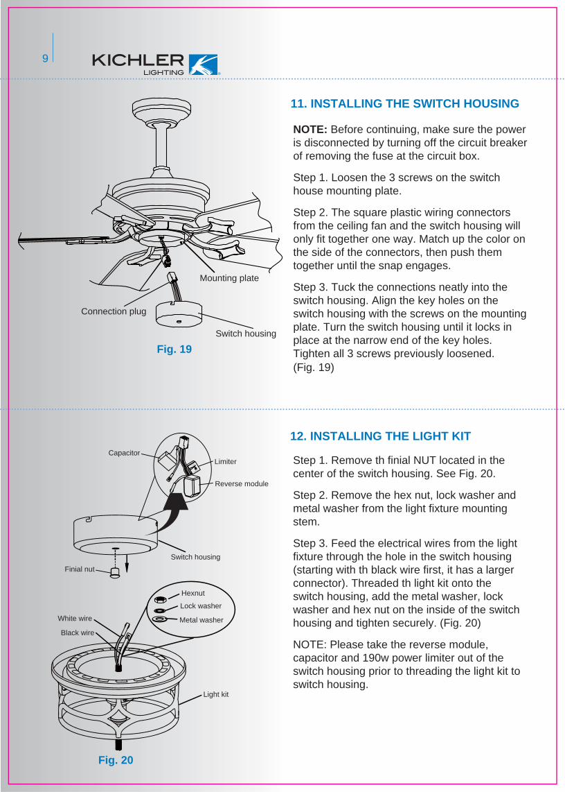
NOTE: Before continuing, make sure the power is disconnected by turning off the circuit breaker of removing the fuse at the circuit box.
Step 1. Loosen the 3 screws on the switch house mounting plate.
Step 2. The square plastic wiring connectors from the ceiling fan and the switch housing will only fit together one way. Match up the color on the side of the connectors, then push them together until the snap engages.
Step 3. Tuck the connections neatly into the switch housing. Align the key holes on the switch housing with the screws on the mounting plate. Turn the switch housing until it locks in place at the narrow end of the key holes. Tighten all 3 screws previously loosened. (Fig. 19)
Step 1. Remove th finial NUT located in the center of the switch housing. See Fig. 20.
Step 2. Remove the hex nut, lock washer and metal washer from the light fixture mounting stem.
Step 3. Feed the electrical wires from the light fixture through the hole in the switch housing (starting with th black wire first, it has a larger connector). Threaded th light kit onto the switch housing, add the metal washer, lock washer and hex nut on the inside of the switch housing and tighten securely. (Fig. 20)
NOTE: Please take the reverse module, capacitor and 190w power limiter out of the switch housing prior to threading the light kit to switch housing.
Model No: PL-190B
AC 120V 60HZ
Power Limit
Max.190W (ON/OFF)
Incandescent or Ballast
LIGHT/BLACK
CapacitorLimiter
Reverse module
Finial nut
White wire
Black wire
Light kit
Lock washer
Metal washer
Hexnut
Switch housing

10Chicago TM
Fig. 22
Fig. 21
Fig. 23
Reversemodule
LimiterLIGHT/BLACK
Power Limit
Max.190W (ON/OFF)
Incandescent or Ballast
AC IN L/RED
AC IN N/WHITEModel No: PL-190B
AC 120V 60HZ
Capacitor
Light kit
Light kit
Mounting plate
Bulb
Manual nut
Silicon washer
Metal washer
Glass shade
Decorative plate
Finial
Step 4. Connect the black wire connectors from the light fixture and switch housing by pushing them together. Follow the same precedure with the white wire connectors. Tear adhesive paper pre-sticking on one side of the reverse module, capacitor and 190w power limiter. Stick them on the inside of switch housing. (Fig. 21)
Step 5. The square plastic wiring connectors from the ceiling fan and the light fixture will only fit together one way. Match up the color on the side of the connectors, then push them together until the snap engages.
Step 6. Loosen the 3 screws on the mounting plate. Tuck the connections neatly into the switch housing. Align the key hole on the switch housing with the screws on the mounting plate. Turn light fixture until it locks in place at the narrow end of the key holes. Tighten all 3 screws previously loosened. (Fig. 22)
Step 1. Install the light bulbs (included). Slide the glass bowl over the threaded pipe. Place the silicon washer, metal washer and thread the manual nut onto the pipe. Place the decorative plate and tighten the glass bowl with the finial. (Fig. 23)
NOTE: This “Energy Policy Act 2005” compliant fan includes a device that limits the total wattage of its light fixture to 190 wattage. By installing a combina-tion of light bulbs that exceeds 190 watts or if an electrical surge causes the wattage to exceed 190 watts, the light fixture will automatically turn off. If this should happen, you will need to reset the light fixture by turning the power off to the ceiling fan and / or light fixture, reinstalling lamps totaling less than 190 watts and then turning the power back on.
YOUR NEW KICHLER CEILING FAN IS NOW READY TO USE. REMEMEBER TO RESTORE ALL POWER.
13. INSTALLING THE LIGHT BULB & GLASS SHAED

Fig. 24
Fig. 25
Fig. 26
14. OPERATING INSTRUCTIONS
Restore power to ceiling fan and test for proper operation.
A. , , and buttons: These three buttons are used to set the fan speed as follows: = low speed = medium speed = high speed
B. button: This button turns the fan off.
D. The " " button:
C. The " " button:
Press and release the button to turn the light ON or OFF. Press and hold the button to set the desired brightness. The light key has an auto-resume, it will stay at the same brightness as the last time it was turned off.
D. The " " button is used to set the fan forward or reverse, press the button forward (for warm weather) or reverse (for cool weather).
Speed settings for warm or cool weather depend on factors such as the room size. Ceiling height, number of fans and so on.
NOTE: To operate the reverse function on this fan, press the reverse button while the fan is running.
Warm weather-(Forward) A downward airflow creates a cooling effect as shown in Fig. 25.This allows you to set your air conditioner on a warmer setting without affecting your comfort.
Cool weather - (Reverse) An upward airflowmoves warm air off the ceiling area as shown in Fig. 26. This allows you to set your heating unit on a cooler setting without affecting your comfort.
Press to turn the upper light on and off, hold for full range dimming. (If your ceiling fan is equipped with an “Upper Light”)
11
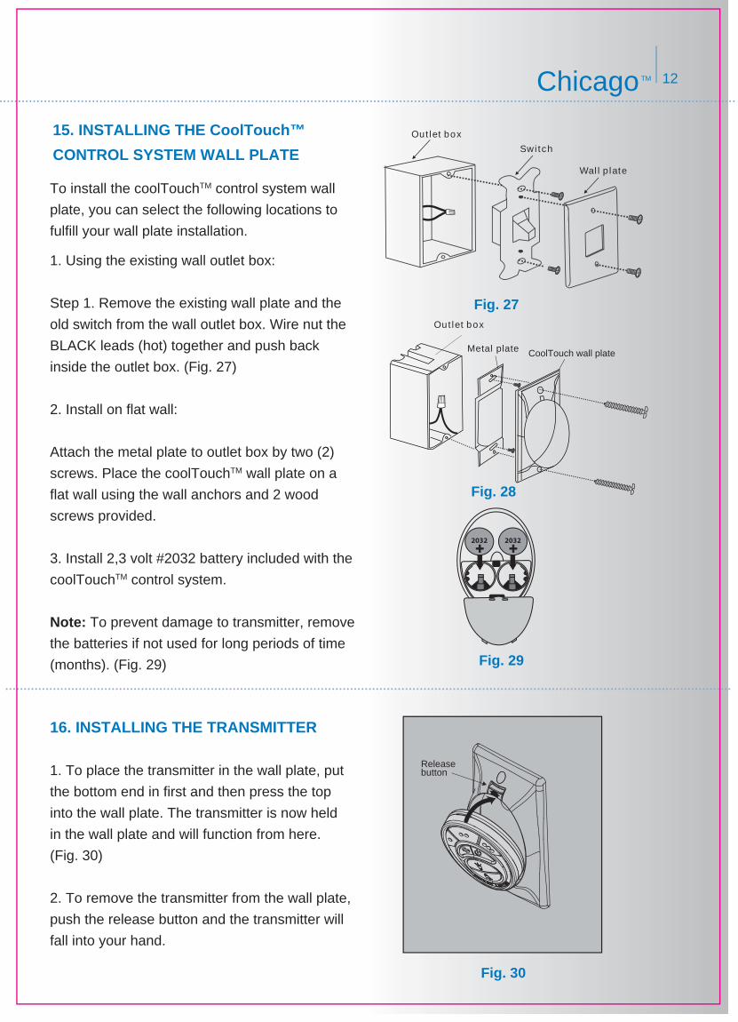
15. INSTALLING THE CoolTouch™
CONTROL SYSTEM WALL PLATE
To install the coolTouchTM control system wall
plate, you can select the following locations to
fulfill your wall plate installation.
1. Using the existing wall outlet box:
Step 1. Remove the existing wall plate and the
old switch from the wall outlet box. Wire nut the
BLACK leads (hot) together and push back
inside the outlet box. (Fig. 27)
2. Install on flat wall:
Attach the metal plate to outlet box by two (2)
screws. Place the coolTouchTM wall plate on a
flat wall using the wall anchors and 2 wood
screws provided.
3. Install 2,3 volt #2032 battery included with the
coolTouchTM control system.
Note: To prevent damage to transmitter, remove
the batteries if not used for long periods of time
(months). (Fig. 29)
16. INSTALLING THE TRANSMITTER
1. To place the transmitter in the wall plate, put
the bottom end in first and then press the top
into the wall plate. The transmitter is now held
in the wall plate and will function from here.
(Fig. 30)
2. To remove the transmitter from the wall plate,
push the release button and the transmitter will
fall into your hand.
Fig. 27
Fig. 28
Fig. 29
Fig. 30
Releasebutton
Wal l p late
Swi tch
Out let box
12ChicagoTM
CoolTouch wall plate
Out let box
Metal plate
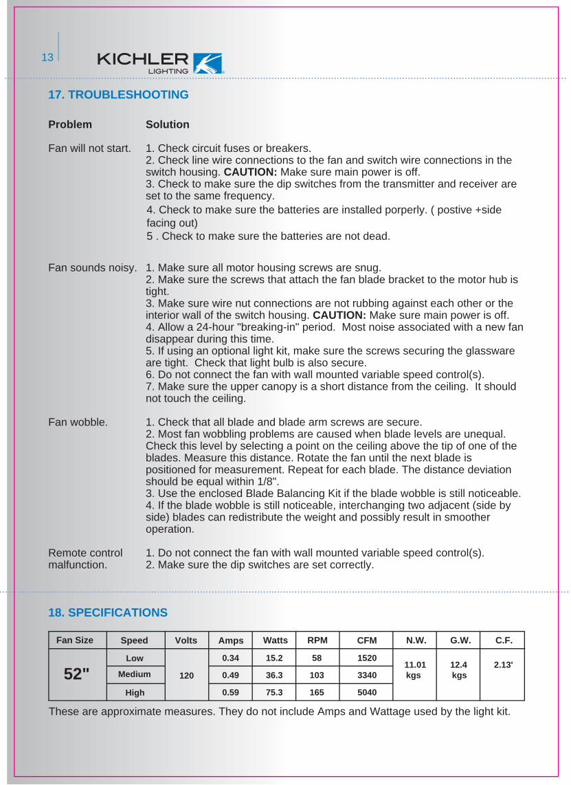
17. TROUBLESHOOTING
18. SPECIFICATIONS
2.13'11.01kgs
12.4kgs
RPM CFM N.W. G.W. C.F.
0.34
0.49
0.59
15.2
36.3
75.3
58
103
165
1520
3340
5040
120
Fan Size
52"
Speed Volts Amps Watts
Low
Medium
High
These are approximate measures. They do not include Amps and Wattage used by the light kit.
Problem
Fan will not start.
Fan sounds noisy.
Fan wobble.
Remote control malfunction.
Solution
1. Check circuit fuses or breakers.2. Check line wire connections to the fan and switch wire connections in the switch housing. CAUTION: Make sure main power is off.3. Check to make sure the dip switches from the transmitter and receiver are set to the same frequency.
1. Make sure all motor housing screws are snug.2. Make sure the screws that attach the fan blade bracket to the motor hub is tight.3. Make sure wire nut connections are not rubbing against each other or the interior wall of the switch housing. CAUTION: Make sure main power is off.4. Allow a 24-hour "breaking-in" period. Most noise associated with a new fan disappear during this time.5. If using an optional light kit, make sure the screws securing the glassware are tight. Check that light bulb is also secure.6. Do not connect the fan with wall mounted variable speed control(s).7. Make sure the upper canopy is a short distance from the ceiling. It should not touch the ceiling.
1. Check that all blade and blade arm screws are secure.2. Most fan wobbling problems are caused when blade levels are unequal. Check this level by selecting a point on the ceiling above the tip of one of the blades. Measure this distance. Rotate the fan until the next blade is positioned for measurement. Repeat for each blade. The distance deviation should be equal within 1/8".3. Use the enclosed Blade Balancing Kit if the blade wobble is still noticeable.4. If the blade wobble is still noticeable, interchanging two adjacent (side by side) blades can redistribute the weight and possibly result in smoother operation.
1. Do not connect the fan with wall mounted variable speed control(s).2. Make sure the dip switches are set correctly.
4. Check to make sure the batteries are installed porperly. ( postive +side facing out)5 . Check to make sure the batteries are not dead.
13