CHF: A scalable topological data structure for tetrahedral...
8
CHF: A scalable topological data structure for tetrahedral meshes MARCOS LAGE 1 , THOMAS LEWINER 1,2 , H´ ELIO LOPES 1 AND LUIZ VELHO 3 1 Department of Mathematics — Pontif´ ıcia Universidade Cat´ olica — Rio de Janeiro — Brazil 2 G´ eom´ etrica Project — INRIA – Sophia Antipolis — France 3 Visgraf Project — IMPA — Rio de Janeiro — Brazil {mlage, tomlew, lopes}@mat.puc--rio.br. [email protected]. Abstract. This work introduces a scalable topological data structure for manifold tetrahedral meshes called Compact Half–Face (CHF). It provides a high degree of scalability, since it is able to optimize the memory consumption / execution time ratio for different applications and data by using features of its different levels. An object–oriented API using class inheritance and virtual instantiation enables a unique interface for each function at any level. CHF requires very few memory, is simple to implement and easy to use, since it substitutes pointers by container of integers and basic bitwise rules. Keywords: Geometric Modeling. Data Structures. Object Oriented Programming. Generic Containers. Figure 1: Visualization of tetrahedral meshes using CHF. 1 Introduction Tetrahedral meshes constitute one of the fundamental rep- resentations for volumetric objects in computer graphics and geometric modeling. Although mesh–less models are very popular in visualization, meshes represent in a unique, lo- cal and explicit manner the underlying geometric space of an object. This is the main reason why these representations are omnipresent for finite element methods. For these ap- plications and many others, the efficiency of the data struc- ture is a crucial element. In particular, generation of meshes from point data is a very active area of research, where ef- ficient data structures as CHF can help in both clarity and efficiency. Nowadays, many geometric modeling and scientific vi- sualization systems commonly have to deal with huge volu- metric models [18, 20]. Several data structures and algorithm have been proposed to visualize and manipulate tetrahedral meshes [26, 17, 10, 21]. However, such structures consume considerable memory, requiring high scalability to handle Preprint MAT. 12/05, communicated on May 15 th , 2005 to the Department of Mathematics, Pontif´ ıcia Universidade Cat´ olica — Rio de Janeiro, Brazil. The corresponding work was published in the proceedings of the Sibgrapi 2005, pp. 349-356. IEEE Press, 2005. large models without losing performance in memory access because of thrashing. Contributions. This work introduces a scalable topological data structure for manifold tetrahedral meshes called Com- pact Half–Face (CHF). This data structure is an improve- ment for the Handle–Face data structure [17] and extends the Corner–Table data structure for surfaces [25]. The main advantages of CHF are threefold. First, it is scalable, since it is able to change the use of memory to improve execution time. The amount of information stored on the data struc- ture can adapt to a specific application or model. Second, it requires very few memory, since it substitutes pointers by container of integers and basic bitwise rules. Moreover, it is very easy to implement and use. And last, its object–oriented API using class inheritance and virtual instantiation enables a unique interface of the same functions for every scale. Paper outline. Section 2 Combinatorial structures for geomet- rical objects introduces some basic concepts of combinatorial structure. Section 3 Previous and related works reviews some related works. Section 4 The CHF Data Structure presents the CHF data structure, while section 5 Operations on the CHF for each level studies the complexity of the basic operations on
Transcript of CHF: A scalable topological data structure for tetrahedral...

CHF: A scalable topological data structure for tetrahedral meshes
MARCOS LAGE1, THOMAS LEWINER1,2 , HELIO LOPES1 AND LUIZ VELHO3
1 Department of Mathematics — Pontifıcia Universidade Catolica — Rio de Janeiro — Brazil2 Geometrica Project — INRIA – Sophia Antipolis — France
3 Visgraf Project — IMPA — Rio de Janeiro — Brazil{mlage, tomlew, lopes}@mat.puc--rio.br. [email protected].
Abstract. This work introduces a scalable topological data structure for manifold tetrahedral meshes calledCompact Half–Face (CHF). It provides a high degree of scalability, since it is able to optimize the memoryconsumption / execution time ratio for different applications and data by using features of its different levels. Anobject–oriented API using class inheritance and virtual instantiation enables a unique interface for each function atany level. CHF requires very few memory, is simple to implement and easy to use, since it substitutes pointers bycontainer of integers and basic bitwise rules.Keywords: Geometric Modeling. Data Structures. Object Oriented Programming. Generic Containers.
Figure 1: Visualization of tetrahedral meshes using CHF.
1 IntroductionTetrahedral meshes constitute one of the fundamental rep-
resentations for volumetric objects in computer graphics andgeometric modeling. Although mesh–less models are verypopular in visualization, meshes represent in a unique, lo-cal and explicit manner the underlying geometric space ofan object. This is the main reason why these representationsare omnipresent for finite element methods. For these ap-plications and many others, the efficiency of the data struc-ture is a crucial element. In particular, generation of meshesfrom point data is a very active area of research, where ef-ficient data structures as CHF can help in both clarity andefficiency.
Nowadays, many geometric modeling and scientific vi-sualization systems commonly have to deal with huge volu-metric models [18, 20]. Several data structures and algorithmhave been proposed to visualize and manipulate tetrahedralmeshes [26, 17, 10, 21]. However, such structures consumeconsiderable memory, requiring high scalability to handle
Preprint MAT. 12/05, communicated on May 15th, 2005 to the Departmentof Mathematics, Pontifıcia Universidade Catolica — Rio de Janeiro, Brazil.The corresponding work was published in the proceedings of the Sibgrapi2005, pp. 349-356. IEEE Press, 2005.
large models without losing performance in memory accessbecause of thrashing.
Contributions. This work introduces a scalable topologicaldata structure for manifold tetrahedral meshes called Com-pact Half–Face (CHF). This data structure is an improve-ment for the Handle–Face data structure [17] and extendsthe Corner–Table data structure for surfaces [25]. The mainadvantages of CHF are threefold. First, it is scalable, sinceit is able to change the use of memory to improve executiontime. The amount of information stored on the data struc-ture can adapt to a specific application or model. Second, itrequires very few memory, since it substitutes pointers bycontainer of integers and basic bitwise rules. Moreover, it isvery easy to implement and use. And last, its object–orientedAPI using class inheritance and virtual instantiation enablesa unique interface of the same functions for every scale.
Paper outline. Section 2 Combinatorial structures for geomet-rical objects introduces some basic concepts of combinatorialstructure. Section 3 Previous and related works reviews somerelated works. Section 4 The CHF Data Structure presents theCHF data structure, while section 5 Operations on the CHF foreach level studies the complexity of the basic operations on
M. Lage, T. Lewiner, H. Lopes and L. Velho 2
the CHF. Section 6 Memory Comparisons compares CHF tosome of the related works.
2 Combinatorial structures for geometrical ob-jectsThis sections introduces the basic concepts that will be
modeled by our data structure. For more details on the fol-lowing definitions, see [1].
Simplices. A simplex σp of dimension p is the closed con-vex hull of p + 1 points {v0, . . . , vp}, vi ∈ Rm, in generalposition, i.e., when the vectors v1− v0, v2− v0, . . . , vp− v0
are linearly independent. For example, simplices of dimen-sions 3, 2, 1 and 0 are, respectively, tetrahedrons, triangles,edges and vertices. The points v0, . . . , vp are called the ver-tices of σ. A face of σ is the convex hull of some but not allof the vertices of σ and therefore is also a simplex. If σ is aface of a simplex τ then τ is said to be incident to σ and τbounds σ. The boundary of a p–simplex σ, denoted by ∂σ,is the collection of all of its faces.
Simplicial Complex. Two k–simplices σ and ρ ∈ K areadjacent when σ ∩ ρ 6= ∅, and independent otherwise. Asimplicial complex K is a finite set of simplices together withall their faces such that if σ and τ are simplices of K, thenthey either meet at a face λ, or are independent.
Stars. The open star of a simplex σ ∈ K, is the union ofall simplices in K having σ as a face. The star of σ ∈ K,denoted by star (σ,K), is the union of all simplices of theopen star together with all their faces (see Figure 2).
Manifolds. A simplicial complex M is a combinatorial k–manifold if the open star of a vertex in M is homeomorphiceither toRk or toRk−1×R+. In particular, if M is a manifold,then every (k−1)–simplex in M is bounding either one or twok–simplex.
A combinatorial k–manifold is orientable when it is pos-sible to choose a coherent orientation for all of its simplices,where coherent means that two adjacent k–faces induce op-posite orientations on their common (k−1)–face. From nowon, a k–manifold will always mean an oriented combinato-rial k–manifold and we will denote by nk be the number ofk–simplices in M .
Figure 2: The star of an inner edge vavb is composed of thetetrahedrons, triangles, edges and vertices drawn.
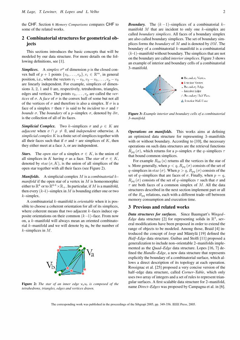
Boundary. The (k−1)–simplices of a combinatorial k–manifold M that are incident to only one k–simplex arecalled boundary simplices. All faces of a boundary simplexare also called boundary simplices. The set of boundary sim-plices forms the boundary of M and is denoted by ∂M . Theboundary of a combinatorial k–manifold is a combinatorial(k−1)–manifold without boundary. The simplices that are noton the boundary are called interior simplices. Figure 3 showsan example of interior and boundary cells of a combinatorial3–manifold.
Figure 3: Example interior and boundary cells of a combinatorial3–manifold.
Operations on manifolds. This works aims at definingan optimized data structure for representing 3–manifoldswith or without boundary. According to [10], the necessaryoperations on such data structures are the retrieval functionsRpq (σ), which returns for a p–simplex σ the q–simplices τthat bound common simplices.
For example R00 (v) returns all the vertices in the star ofv. More generally, when p < q, Rpq (σ) consists of the set ofq–simplices in star (σ). When p > q, Rpq (σ) consists of theset of q–simplices that are faces of σ. Finally, when p = q,Rpq (σ) consists of the set of q–simplices τ such that σ andτ are both faces of a common simplex of M . All the datastructures described in the next section implement part or allof the Rpq relations, each with a different trade–off betweenmemory consumption and execution time.
3 Previous and related worksData structures for surfaces. Since Baumgart’s Winged–Edge data structure [2] for representing solids in R3, sev-eral modifications have been proposed in order to extend therange of objects to be modeled. Among those, Braid [4] in-troduced the concept of loop and Mantyla [19] defined theHalf–Edge data structure. Guibas and Stolfi [11] proposed ageneralization to include non–orientable 2–manifolds imple-mented as the Quad–Edge data structure. Lopes [16, 7] de-fined the Handle–Edge, a new data structure that representsexplicitly the boundary of a combinatorial surface, which al-lows a direct description of its topology at each operation.Rossignac et al. [25] proposed a very concise version of thehalf–edge data structure, called Corner–Table, which onlyuses two array of integers and a set of rules to represent trian-gular surfaces. A first scalable data structure for 2–manifold,name Direct–Edges was proposed by Campagna et al. in [6].
The corresponding work was published in the proceedings of the Sibgrapi 2005, pp. 349-356. IEEE Press, 2005.

3 CHF: A scalable topological data structure for tetrahedral meshes
Data structure for 3–manifolds. For three dimensionalmanifolds representation, other data structures have beendeveloped. Dobkin and Laszlo [9], with their Facet–Edgedata structure, extended Guibas and Stolfi’s scheme in or-der to represent cell complexes that are subdivisions of the3–dimensional sphere. After that, Lopes and Tavares [17] in-troduced the Handle–Face data structure that explicitly rep-resents the boundaries.
Data structure for n–manifolds. Generalizing the idea ofthe Quad–Edge and Facet–Edge, some significant workswere introduced to represent n–dimensional manifold.Among those, the Cell–Tuple data structure by Brisson [5],the n–Generalized Maps for simplicial quasi–manifoldsby Lienhardt [15] and the Hypermaps by Bertrand andDufourd [3] are to be cited.
Cell representation. According to Brisson [5], among allthe above cited dimension–independent data structures, onlythe Quad–Edge and the Facet–Edge do not explicit rep-resents each cell, while the Winged–Edge, the Half–Edge,the Handle–Edge, and the Handle–Face are examples ofdata structures with explicit representation of cells. Anotherwidely used dimension–independent explicit representationis the Indexed data structure with adjacencies proposed byPaoluzzi et al. [22].
Non–manifold data structures. Traditional non–manifoldmodels usually results from Boolean operations. Weiler [26]was the first to propose a non–manifold data structure, calledRadial–Edge. After that, several modifications have beensuggested to deal with specific applications. Some substan-tial contributions to non–manifolds representation includethe works of Wu [27, 28], Yamaguchi and Kimura [29],Gursoz [12], Rossignac and O’Connor [24], Cavalcanti etal. [8], and Lee and Lee [14]. More recently, de Floriani andHui [10] presented a very concise data structure for non–manifold manipulation, called NMIA, which is an extensionof the Indexed data structure with adjacencies, and Pesco etal. proposed the Handle–Cell [23], which is an extension ofthe Handle–Edge, to deal with general 2–dimensional cellcomplexes. Finally, Nonato et al. [21] proposed SingularHandle–Face, an extension of the Handle–Face in order todeal with some non–manifold cases. All the above structuresrepresent the cells explicitly.
The CHF proposal. The CHF data structure has beencreated to represent 3–manifolds. It extends the Corner–Table [25] to volumes and at the same time can be considereda concise version of the Handle–Face [17], since its volumet-ric cells are simplices. It uses generic containers instead ofpointers or static arrays. Similarly to the Corner–Table, it ex-plicitly represents a few adjacencies and incidence relationsbetween cells and uses a set of rules to obtain the others.However, CHF has a very different and important character-istic that is its scalability, since it can change in size accord-ing to the application.
4 The CHF Data StructureThe objective of this section is to introduce the CHF
data structure for the representation of 3–dimensional mani-folds with or without boundary. There are actually four lev-els of structures, each one completing the previous in orderto accelerate the execution time, but consuming a little morememory at each step. Those levels are implicit to the pro-grammer by virtual inheritance: a C++ feature that avoidsthe programmer to care about which structure level he is us-ing. The compiler simply generates at the beginning of eachfunction a piece of code like:
Operation Rpq (σ) at level i;if has level i+1 then
RETURN Operation Rpq (σ) at level i+1;end if(. . . )This section describes the four levels of the CHF data
structure, with their construction from the first level. Thenext section will describe the main operations on each ofthose levels.
(a) Level 0: representing tetrahedrons by the Vertex con-tainer
The CHF uses the concept of half–face (see Figure 4)to represent the association of a tetrahedron with one ofits bounding triangles, or equivalently the association ofthis triangle with its apex. Any access to the elements of atetrahedron is performed through its half–faces. The level 0if the CHF represents only the tetrahedral soup (see Figure 5)by storing the apex of each half–faces.
Figure 4: One half–face of a tetrahedron.
In the CHF data structure, the half–faces, the vertices andthe tetrahedrons are indexed by non–negative integers. Eachtetrahedron is represented by 4 consecutive half–faces thatdefine its orientation. For example, half–faces 0, 1, 2 and 3correspond to the first tetrahedron, the half–faces 4, 5, 6 and7 correspond to the second tetrahedron and so on. . .
Vertex geometry. The representation of the mesh geometryis done by the use of a container, named G[], that stores thegeometry (coordinates, normals,. . . ) of the n0 vertices in M .For example, the geometry of a vertex with index Vid v isobtained by accessing G[v].
Preprint MAT. 12/05, communicated on May 15th, 2005 to the Department of Mathematics, Pontifıcia Universidade Catolica — Rio de Janeiro, Brazil.
M. Lage, T. Lewiner, H. Lopes and L. Velho 4
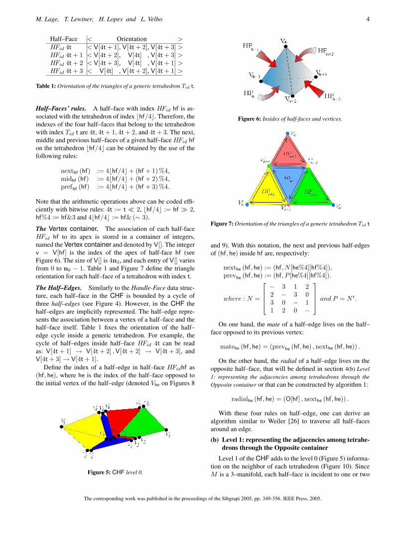
Half–Face < Orientation >HFid 4t < V[4t + 1], V[4t + 2], V[4t + 3] >HFid 4t + 1 < V[4t + 2], V[4t] , V[4t + 3] >HFid 4t + 2 < V[4t + 3], V[4t] , V[4t + 1] >HFid 4t + 3 < V[4t] , V[4t + 2], V[4t + 1] >
Table 1: Orientation of the triangles of a generic tetrahedron Tid t.
Half–Faces’ rules. A half–face with index HFid hf is as-sociated with the tetrahedron of index bhf/4c. Therefore, theindexes of the four half–faces that belong to the tetrahedronwith index Tid t are 4t, 4t + 1, 4t + 2, and 4t + 3. The next,middle and previous half–faces of a given half–face HFid hfon the tetrahedron bhf/4c can be obtained by the use of thefollowing rules:
nexthf (hf) := 4bhf/4c+ (hf + 1)%4,midhf (hf) := 4bhf/4c+ (hf + 2)%4,prefhf (hf) := 4bhf/4c+ (hf + 3)%4.
Note that the arithmetic operations above can be coded effi-ciently with bitwise rules: 4t := t ¿ 2, bhf/4c := hf À 2,hf%4 := hf&3 and 4bhf/4c := hf&(∼ 3).
The Vertex container. The association of each half-faceHFid hf to its apex is stored in a container of integers,named the Vertex container and denoted by V[]. The integerv = V[hf] is the index of the apex of half-face hf (seeFigure 6). The size of V[] is 4n3, and each entry of V[] variesfrom 0 to n0 − 1. Table 1 and Figure 7 define the triangleorientation for each half–face of a tetrahedron with index t.
The Half–Edges. Similarly to the Handle-Face data struc-ture, each half–face in the CHF is bounded by a cycle ofthree half–edges (see Figure 4). However, in the CHF thehalf–edges are implicitly represented. The half–edge repre-sents the association between a vertex of a half–face and thehalf–face itself. Table 1 fixes the orientation of the half–edge cycle inside a generic tetrahedron. For example, thecycle of half–edges inside half–face HFid 4t can be readas: V[4t + 1] → V[4t + 2] , V[4t + 2] → V[4t + 3], andV[4t + 3]→ V[4t + 1].
Define the index of a half–edge in half–face HFidhf as(hf, he), where he is the index of the half–face opposed tothe initial vertex of the half–edge (denoted Vhe on Figures 8
Figure 5: CHF level 0.
Figure 6: Insides of half-faces and vertices.
Figure 7: Orientation of the triangles of a generic tetrahedron Tid t
and 9). With this notation, the next and previous half-edgesof (hf, he) inside hf are, respectively:
nexthe (hf, he) := (hf, N [he%4][hf%4]),prevhe (hf, he) := (hf, P [he%4][hf%4]).
where : N =
− 3 1 22 − 3 03 0 − 11 2 0 −
and P = N t.
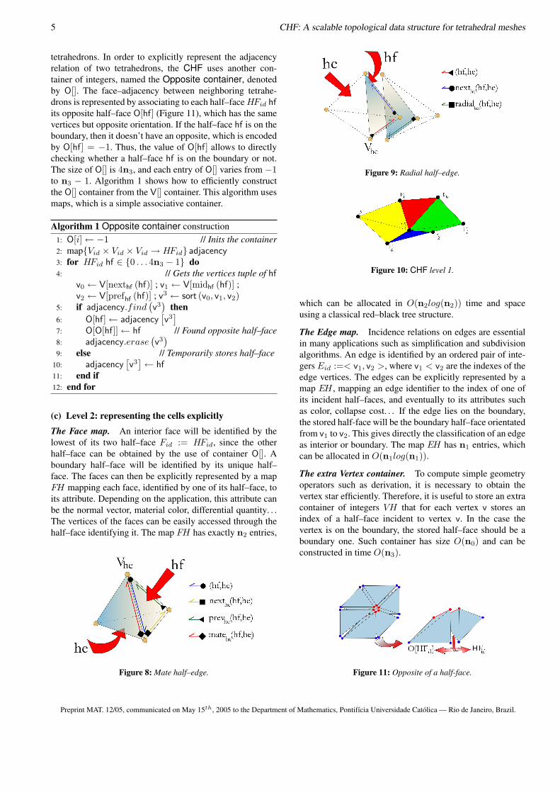
On one hand, the mate of a half–edge lives on the half–face opposed to its previous vertex:
matehe (hf, he) = (prevhe (hf, he) , nexthe (hf, he)) .
On the other hand, the radial of a half–edge lives on theopposite half–face, that will be defined in section 4(b) Level1: representing the adjacencies among tetrahedrons through theOpposite container or that can be constructed by algorithm 1:
radialhe (hf, he) = (O[hf] , nexthe (hf, he)) .
With these four rules on half–edge, one can derive analgorithm similar to Weiler [26] to traverse all half–facesaround an edge.
(b) Level 1: representing the adjacencies among tetrahe-drons through the Opposite container
Level 1 of the CHF adds to the level 0 (Figure 5) informa-tion on the neighbor of each tetrahedron (Figure 10). SinceM is a 3–manifold, each half–face is incident to one or two
The corresponding work was published in the proceedings of the Sibgrapi 2005, pp. 349-356. IEEE Press, 2005.
5 CHF: A scalable topological data structure for tetrahedral meshes
tetrahedrons. In order to explicitly represent the adjacencyrelation of two tetrahedrons, the CHF uses another con-tainer of integers, named the Opposite container, denotedby O[]. The face–adjacency between neighboring tetrahe-drons is represented by associating to each half–face HFid hfits opposite half–face O[hf] (Figure 11), which has the samevertices but opposite orientation. If the half–face hf is on theboundary, then it doesn’t have an opposite, which is encodedby O[hf] = −1. Thus, the value of O[hf] allows to directlychecking whether a half–face hf is on the boundary or not.The size of O[] is 4n3, and each entry of O[] varies from −1to n3 − 1. Algorithm 1 shows how to efficiently constructthe O[] container from the V[] container. This algorithm usesmaps, which is a simple associative container.
Algorithm 1 Opposite container construction1: O[i]← −1 // Inits the container2: map{Vid × Vid × Vid → HFid} adjacency3: for HFid hf ∈ {0 . . . 4n3 − 1} do4: // Gets the vertices tuple of hf
v0 ← V[nexthf (hf)] ; v1 ← V[midhf (hf)] ;v2 ← V[prefhf (hf)] ; v3 ← sort (v0, v1, v2)
5: if adjacency.find(v3
)then
6: O[hf]← adjacency[v3
]7: O[O[hf]]← hf // Found opposite half–face8: adjacency.erase
(v3
)9: else // Temporarily stores half–face
10: adjacency[v3
]← hf11: end if12: end for
(c) Level 2: representing the cells explicitly
The Face map. An interior face will be identified by thelowest of its two half–face Fid := HFid, since the otherhalf–face can be obtained by the use of container O[]. Aboundary half–face will be identified by its unique half–face. The faces can then be explicitly represented by a mapFH mapping each face, identified by one of its half–face, toits attribute. Depending on the application, this attribute canbe the normal vector, material color, differential quantity. . .The vertices of the faces can be easily accessed through thehalf–face identifying it. The map FH has exactly n2 entries,
Figure 8: Mate half–edge.
Figure 9: Radial half–edge.
Figure 10: CHF level 1.
which can be allocated in O(n2log(n2)) time and spaceusing a classical red–black tree structure.
The Edge map. Incidence relations on edges are essentialin many applications such as simplification and subdivisionalgorithms. An edge is identified by an ordered pair of inte-gers Eid :=< v1, v2 >, where v1 < v2 are the indexes of theedge vertices. The edges can be explicitly represented by amap EH , mapping an edge identifier to the index of one ofits incident half–faces, and eventually to its attributes suchas color, collapse cost. . . If the edge lies on the boundary,the stored half-face will be the boundary half–face orientatedfrom v1 to v2. This gives directly the classification of an edgeas interior or boundary. The map EH has n1 entries, whichcan be allocated in O(n1log(n1)).
The extra Vertex container. To compute simple geometryoperators such as derivation, it is necessary to obtain thevertex star efficiently. Therefore, it is useful to store an extracontainer of integers VH that for each vertex v stores anindex of a half–face incident to vertex v. In the case thevertex is on the boundary, the stored half–face should be aboundary one. Such container has size O(n0) and can beconstructed in time O(n3).
Figure 11: Opposite of a half-face.
Preprint MAT. 12/05, communicated on May 15th, 2005 to the Department of Mathematics, Pontifıcia Universidade Catolica — Rio de Janeiro, Brazil.

M. Lage, T. Lewiner, H. Lopes and L. Velho 6
(d) Level 3: representing the boundary through a Com-pact Half–Edge
The boundary of a combinatorial 3–manifold is a setof combinatorial 2–manifolds without boundary. Lopes andTavares in [17] pointed out the importance of having effi-cient boundary cells manipulation for building and unbuild-ing 3-manifolds. Moreover, advancing front triangulations isa very significant application that needs an explicit represen-tation of the boundary. To do so, the incidences and adja-cencies of cells on the boundary should be explicitly repre-sented. In the CHF such representation is done by the use ofthe Compact Half–Edge (CHE) data structure, which is aversion of the CHF for surfaces.
The CHE [13] is also a scalable data-structure. Similarlyto CHF, the first level of CHE has only the Vertex con-tainer. The second level includes the Opposite containerfor the half–edges. The third level represents the cells ex-plicitly. And finally, the fourth level introduces an explicitrepresentation for the boundary curves.
Here, the CHF implements the second level of CHE, i.e.,it uses two containers of integers, the bV[] container and thebO[] container. The vertices of CHE and CHF have the sameindex, and the CHE does not need to store the vertex ge-ometry for level 0. Each boundary triangle is representedby 3 consecutive oriented–edges that define its frontier. Inthe CHE, the oriented–edges 0, 1, and 2 correspond to thefirst triangle, the oriented–edges 3, 4, and 5 correspond tothe second triangle and so on. . . The bV[] container storesthe indexes of the vertices of the boundary triangles. ThebO[] container stores in each entry the index of the oppositeoriented–edge on the boundary surface. Those two contain-ers are obtained in linear time traversing V[] and O[].
5 Operations on the CHF for each levelThis section discusses the computational performance of
some Rpq relations at all levels of the CHF.
(a) R0∗: the vertex star
The vertex star is essential in particular to volume model-ing. The CHF answers relations R0∗ in time O(n3) at level0, since the function has to transverse all the V[] container.At level 1, the V[] container is traversed until one half–faceincident to the input vertex is found, after that the vertex staris obtained in time O(deg(v)) by the use of the O[] and therules described above. Thus, the worst case at level 1 hascomplexity O(n3), but it is in average deg(v) times fasterthan for level 0. Finally, at level 2 and 3 the complexity offinding the star of a vertex v is reduced to O(deg(v)), sinceVH directly stores the starting half–face to traverse the ver-tex star.
(b) R1∗: the edge star
The edge star is also very important to several kind ofalgorithms, such as volume simplification schemes usingedge collapse. Here, the edge is considered as an ordered pairof indexes of its vertices. Thus, R10 is directly answered.
Algorithm 2 R13 (Eid < v1, v2 >), level 01: container< Vid > R13
2: for HFid hf ∈ {0 . . . 4n3 − 1} do // all half–faces3: if v1 == V[hf] and
(v2 = V[nexthf (hf)] or v2 = V[midhf (hf)]or v2 = V[prefhf (hf)]) then
4: R13.insert(hf À 2) ; continue // add tetrahedron5: end if6: end for
At level 0, the time complexity for the CHF to answer therelations R12 and R13 is O(n3), since the method has totransverse all the V[] container (see algorithm 2). At level1, again the V[] container is traversed to find a half–faceincident to the input edge, after that by the use of the O[]container and the rules for mate and radial, the cycle ofhalf–faces around the edge is obtained in time O(deg(e)),where deg(e) is the number of faces incident to e. The worstcase for level 1 has complexity time O(n3) but it is inaverage deg(e) times faster than for level 0. Finally, at level2 and 3 the complexity is reduced to O(deg(e)), since EHdirectly identifies the first half–face (see algorithm 3).
Algorithm 3 R13 (Eid < v1, v2, (hf0, he0) >), level 31: container< Vid > R13
2: Tid t0 ← bhf0/4c // first tetrahedron3: HFid hf ← hf0 ; HEid he← he0 ; Tid t← t04: repeat5: R13.insert(t); // insert to the result6: (hf, he)← radialhe (hf, he) // radial mate7: t← bhf/4c // next tetrahedron8: until hf 6= −1 and t 6= t0
(c) R2∗: the face star
Obtaining the face star is simpler than the edge and vertexstar. Since a face is identified by one of its half–face hf,we can get its vertices directly by v0 = V[nexthf (hf)],v1 = V[midhf (hf)], v2 = V[prefhf (hf)], answering R20
in constant time at any level. The edges v0v1, v1v2, v2v0,can also be retrieved, answering R21 in constant time at anylevel. At level 0, to answer R22 and R23 the methods haveto transverse all the V[] container to find the opposite half–face if any, therefore the time complexity is O(n3) for bothrelations. At level 1 and above, the complexity is reduced toO(1), since the face is identified by one of its incident half–faces and the O[] container gives the other one directly.
(d) R3∗: tetrahedron incidence and adjacency
All the incidences of a tetrahedron are answered in con-stant time at all levels of the CHF, except at level 0 where thequery for adjacent tetrahedrons, R33, is answered in O(n3).At level 1, 2 and 3 by the use of the O[] container, the queryis obtained in O(1) time.
The corresponding work was published in the proceedings of the Sibgrapi 2005, pp. 349-356. IEEE Press, 2005.

7 CHF: A scalable topological data structure for tetrahedral meshes
6 Memory Comparisons
memory consumptionHandle–Face 135n3 + 10n2 + 12n1 + 10n0
CHF 0 4n3
CHF 1 8n3
CHF 2 8n3 + n2 log2 n2 + n1 log2 n1 + n0
CHF 3 CHF 2 + 6 card(∂M2
)
Table 2: Memory complexity for topology.
All data structures described in section 3 Previous and re-lated works provide different trade–offs between memory us-age and time complexity of basic operations such as identi-fying a simplex, accessing its vertices, computing its stars.When handling huge amount of data, a programmer has al-ways to balance the memory consumption with the timecomplexity. We compared CHF with the unique structurespecific to 3–manifolds that has an explicit representationfor cells and for the boundary: the Handle–Face [17] (see ta-ble 2). In a real context, the structure can be adapted in threecomplementary ways. First, the programmer can choose touse a specific level for the whole program. Second, a set ofrules can be defined to decide dynamically which level of-fers the best memory consumption / execution time trade–off. Last, the whole structure can be first reserved, dynam-ically filled each time a query is performed and completedwhen filled more than a given ratio.
7 Conclusions and Future WorksThe main contribution of this paper is an introduction
of an efficient data structure for 3–manifold representation,called CHF. The CHF is straightforward to use, concise andeasy to implement. Moreover, it can adapt its size accordingto its necessity by the use of inheritance. The use of contain-ers makes the CHF implementation clear and general.
In order to illustrate its use, Figure 1 shows some simplevisualization examples using the CHF. The first picture is anexample of a wire-frame visualization of a scalar field de-fined on a molecule. The second illustrates some isosurfacesof a scalar field defined on the Stanford Bunny. The thirdone shows in blue the boundary vertices and in red the inte-rior ones. Finally, the last picture shows in different colorsthe several boundary components of the volume mesh.
The authors plan to extend the CHF in order to considernon-manifolds. In that case, the scalable level structure ofCHF is used again by adding one level to deal with 3-complexes with singular vertices, and another one to dealwith singular edges. This extension is straightforward in bothcases, replacing the map containers used in CHF by multi-maps.
AcknowledgmentsThe authors would like to thank Pierre Alliez (INRIA)
for the volumetric models. Marcos Lage is supported by
CAPES. Helio Lopes is partially supported by CNPq andFAPERJ (contract E261170.693/2004).
References[1] J. W. Alexander. The combinatorial theory of com-
plexes. Annals of Mathematics, 31:219–320, 1930.
[2] B. G. Baumgart. A Polyhedron Representation for Com-puter Vision. AFIPS National Computer Conference,44:589–596, 1975.
[3] Y. Bertrand and J.-F. Dufourd. Algebraic Specificationof a 3D–Modeler Based on Hypergraphs. CVGIP Graph-ical Models and Image Processing, 56:29–60, 1994.
[4] I. C. Braid, R. C. Hillyard and I. A. Stroud. Step-wise construction of polyhedra in geometric modeling.In K. W. Brodlie, editor, Mathematical Methods in Com-puter Graphics and Design, pages 123–141. AcademicPress, 1980.
[5] E. Brisson. Representing Geometric Structures in d Di-mensions: Topology and Order. Discrete and Computa-tional Geometry, 9:387–426, 1993.
[6] S. Campagna, L. Kobbelt and H.-P. Seidel. Directededges: A scalable representation for triangle meshes.Journal of Graphics Tools, 3(4):1–11, 1998.
[7] A. Castelo, H. Lopes and G. Tavares. HandlebodyRepresentation for Surfaces and Morse Operators. InCurves and Surfaces in Computer Vision Graphics III,pages 270–283, 1992.
[8] P. Roma Cavalcanti, P. C. P. Carvalho and L. F. Martha.Non–Manifold modelling: an approach based on spatialsubdivision. Computer–Aided Design, 29(3):209–220,1997.
[9] D. P. Dobkin and M. J. Laszlo. Primitives for the manip-ulation of three–dimensional subdivisions. Algorithmica,4:3–32, 1989.
[10] L. de Floriani and A. Hui. A scalable data structure forthree–dimensional non–manifold objects. In Symposiumon Geometry processing, pages 72–82. ACM, 2003.
[11] L. J. Guibas and J. Stolfi. Primitives for the manip-ulation of general subdivisions and the computation ofVoronoi diagrams. Transactions on Graphics, 4:74–123,1985.
[12] E. L. Gursoz, Y. Choi and F. B. Prinz. Vertex–BasedRepresentation of Non–Manifold Boundaries. In J. U.Turner, M. J. Wozny and K. Preiss, editors, GeometricModeling for Product Engineering, pages 107–130. El-sevier, 1990.
[13] M. Lage, T. Lewiner, H. Lopes and L. Velho. CHE: Ascalable topological data structure for triangular meshes.Technical report, PUC — Rio de Janeiro, 2005.
Preprint MAT. 12/05, communicated on May 15th, 2005 to the Department of Mathematics, Pontifıcia Universidade Catolica — Rio de Janeiro, Brazil.
M. Lage, T. Lewiner, H. Lopes and L. Velho 8
[14] S. Lee and K. Lee. Partial Entity Structure: A CompactNon–Manifold Boundary Representation Based on PartialTopological Entities. In Solid Modeling and Applications,pages 159–170. ACM, 2001.
[15] P. Lienhardt. N–dimensional Generalized Combinato-rial Maps and Cellular Quasi–Manifolds. Journal of Com-putational Geometry & Applications, 4:275–324, 1994.
[16] H. Lopes. Algorithm to build and unbuild 2 and 3 di-mensional manifolds. PhD thesis, Department of Mathe-matics, PUC–Rio, 1996.
[17] H. Lopes and G. Tavares. Structural operators formodeling 3–manifolds. In C. Hoffman and W. Bronsvort,editors, Solid Modeling and Applications, pages 10–18.ACM, 1997.
[18] H. Lopes, G. Nonato, S. Pesco and G. Tavares. Dealingwith topological singularities in volumetric reconstruc-tion. In P.-J. Laurrent, P. Sabloniere and L. Schumaker,editors, Curve and Surface Design, pages 229–238, SaintMalo, 2000. Vanderbilt University Press.
[19] M. Mantyla. An Introduction to Solid Modeling. Com-puter Science Press, Rockville, 1988.
[20] G. Nonato, R. Minghim, M. C. F. de Oliveira andG. Tavares. A Novel Approach for Delaunay 3D Recon-struction with a comparative analysis in the Light of Ap-plications. Computer Graphics Forum, 20(2):161–174,2001.
[21] G. Nonato, A. Castelo, R. Minghim and H. Hideraldo.Topological tetrahedron characterization with applicationin volume reconstruction. Journal of Shape Modeling,11(2), 2005.
[22] A. Paoluzzi, F. Bernardini, C. Cattani and V. Ferrucci.Dimension–independent modeling with simplicial com-plexes. Transactions on Graphics, 12(1):56–102, 1993.
[23] S. Pesco, H. Lopes and G. Tavares. A StratificationApproach for Modeling 2–cell complexes. Computers &Graphics, 28(2):235–247, 2004.
[24] J. Rossignac and M. A. O’Connor. SGC : A DimensionIndependent Model for Pointsets with Internal Structuresand Incomplete Boundaries. In J. U. Turner, M. J. Woznyand K. Preiss, editors, Geometric Modeling for ProductEngineering, pages 145–180. Elsevier, 1990.
[25] J. Rossignac, A. Safonova and A. Szymczak. 3DCompression Made Simple: Edgebreaker on a Corner–Table. In Shape Modeling International, pages 278–283.IEEE, 2001.
[26] K. J. Weiler. Topological Structures for GeometricModeling. PhD thesis, Rensselaer Polytechnic Institute,New York, USA, 1986.
[27] S. T. Wu. A new combinatorial model for boundaryrepresentation. Computers & Graphics, 13(4):477–486,1989.
[28] S. T. Wu. Non–manifold data models: implementationissue. In MICAD, Computer Graphcis and ComputerAided Technologies, pages 37–56, 1992.
[29] Y. Yamaguchi and F. Kimura. Non–Manifold TopologyBased on Coupling Entities. Computers & Graphics,15(1):42–50, 1995.
The corresponding work was published in the proceedings of the Sibgrapi 2005, pp. 349-356. IEEE Press, 2005.