CHEVRON CANOPY - LSI...
26
INSTALLATION SHEET 1 OF 26 INSTRUCTIONS: 5100240A REV. 08/04/2009 JDE# 335640 CHEVRON CANOPY GUIDE (Effective April 2008)
Transcript of CHEVRON CANOPY - LSI...

INSTALLATION
SHEET 1 OF 26INSTRUCTIONS: 5100240A REV. 08/04/2009
JDE# 335640
CHEVRON CANOPYGUIDE (Effective April 2008)
SHEET 2 OF 26INSTRUCTIONS: 5100240B REV. 08/04/2009
SHEET NO.
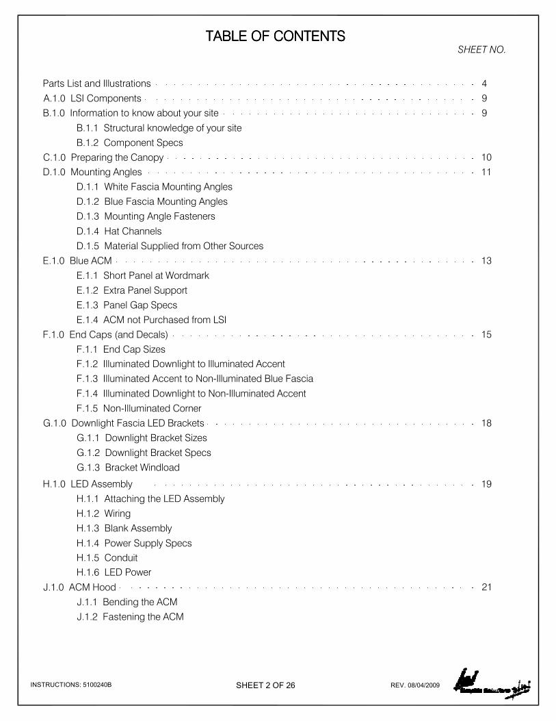
A.1.0 LSI Components 9
B.1.0 Information to know about your site 9
B.1.1 Structural knowledge of your site
B.1.2 Component Specs
TABLE OF CONTENTSTABLE OF CONTENTSTABLE OF CONTENTSTABLE OF CONTENTS
C.1.0 Preparing the Canopy 10
D.1.0 Mounting Angles 11
D.1.1 White Fascia Mounting Angles
D.1.2 Blue Fascia Mounting Angles
D.1.3 Mounting Angle Fasteners
D.1.4 Hat Channels
D.1.5 Material Supplied from Other Sources
13E.1.0 Blue ACM
E.1.1 Short Panel at Wordmark
E.1.2 Extra Panel Support
E.1.3 Panel Gap Specs
E.1.4 ACM not Purchased from LSI
F.1.0 End Caps (and Decals) 15
F.1.1 End Cap Sizes
F.1.2 Illuminated Downlight to Illuminated Accent
F.1.3 Illuminated Accent to Non-Illuminated Blue Fascia
F.1.4 Illuminated Downlight to Non-Illuminated Accent
F.1.5 Non-Illuminated Corner
G.1.0 Downlight Fascia LED Brackets 18
G.1.1 Downlight Bracket Sizes
G.1.2 Downlight Bracket Specs
G.1.3 Bracket Windload
H.1.0 LED Assembly 19
H.1.3 Blank Assembly
J.1.0 ACM Hood 21
J.1.1 Bending the ACM
J.1.2 Fastening the ACM
H.1.1 Attaching the LED Assembly
H.1.2 Wiring
H.1.4 Power Supply Specs
H.1.6 LED Power
H.1.5 Conduit
Parts List and Illustrations 4

Please review site plans before proceeding. Contact LSI Graphic Solutions Plus Customer
Service at 1-(800) 678-2001 for installation support.
Read through all of the instructions prior to beginning installation, and verify (using the packing
list) that all parts have been received and are in good condition.
SHEET 3 OF 26INSTRUCTIONS: 5100240C REV. 08/04/2009
SHEET NO.TABLE OF CONTENTSTABLE OF CONTENTSTABLE OF CONTENTSTABLE OF CONTENTS
K.1.0 Accent Band LED Brackets 22
K.1.1 Accent Bracket Size
K.1.2 Accent Bracket Specs
K.1.4 Accent LED Assembly
K.1.3 Windload
L.1.0 White ACM (Bullnose and Flat) 24
L.1.1 Level 1 Canopy
L.1.2 Level 2 Canopy
L.1.3 Non-Illuminated Returns
L.1.4 Level 3 and 4 Canopy
M.1.0 Specification and Loading - Certifications 25
M.1.1 Fascia Panels
M.1.2 Brackets
M.1.3 Fasteners
M.1.4 Engineer Assistance
M.1.5 Lighting
M.1.6 Components
M.1.7 Sectional Signs
N.1.0 Energy Consumption 26
P.1.0 Title 24 26
Q.1.0 Shortages or Freight Damage Claims 26

SHEET 4 OF 26INSTRUCTIONS: 5100240D REV. 08/04/2009
3"
LED Downlight strip 72"
Part No. 334677
LED Downlight strip 36"
Part No. 334812
LED Accent strip 90"
Part No. 334848
LED Accent strip 36"
Part No. 334850
LED Power Source Asy
Part No. 328699
3 7/8"
36"
3 7/8"
72"
2 5/16"
90"
36"
19"
LED Lighting
Mounting Angles
AL Mounting Angle
White bottom fascia
Part No. 329011 4 1/2"
1 1/2"
144"
120"
AL Mounting Angle
White bottom return
Part No. 3290105"
1"
110"
AL Mounting Angle
Mill top fascia & return
Part No. 99142 1"
1"
2 5/16"

SHEET 5 OF 26INSTRUCTIONS: 5100240E REV. 08/04/2009
146"
35 1/2"
142 3/4"
V.O.
39"
36"
V.O.
146"
41 1/2"
142 3/4"
V.O.
45"
42"
V.O.
39"
19 7/16"
35 1/2"
16 3/16"
V.0.
36"
V.O.
Blue Fascia
45"
31 13/16"
41 1/2"
28 9/16"
V.0.
42"
V.O.
Fascia ACM 42 x 30.625 Blue
Part No.244222
Fascia ACM 36 x 16.192 Blue
Part No. 317879
Fascia ACM 36 x 142.75 Blue
Part No. 317878
Fascia ACM 42 x 142.75 Blue
Part No. 319306
End Caps
Level 1 Non-Illum Back
Part No. 293256
LH & RH White Level 1
Part No. 293262
Fascia Radius End Cap SetRadius LH & RH White
Part No. 329016
White Level 3
Square End Cap No Bevel*Note: Rout line on ACM fascia is
shown as a dashed line in
above illustrations.
Level 2 Non-Illum Back
Part No. 304180
Straight LH & RH White
LH & RH White Level 2
Part No. 304179
Fascia Straight End Cap Set

SHEET 6 OF 26INSTRUCTIONS: 5100240F REV. 08/04/2009
Level 1 Non-Illum Back
Part No. 293259
8"
LH & RH White Level 1
Part No. 239224
Fascia Radius End Cap SetRadius LH & RH White
End Caps Continued
Part No. 329015
White Level 3
Square End Cap No Bevel
White Returns 28"
120"
36" Canopy Radiused Level 1
Part No. 293267
Radiused ACM 28 x 120 White 146"
142 3/4"
V.O.
37 1/2"
28"
V.O.
For 36" Flat Fascia Level 2
Part No. 304185
Straight ACM 28 x 142.75 White
Level 2 Non-Illum Back
Part No. 304176
Straight LH & RH White
LH & RH White Level 2
Part No. 304177
Fascia Straight End Cap Set
6 9/16"

SHEET 7 OF 26INSTRUCTIONS: 5100240G REV. 08/04/2009
White Returns Continued
32"
120"
42" Canopy Radiused Level 1
Part No. 239204
Radiused ACM 32 x 120 White
6 9/16"
146"
142 3/4"
V.O.
41 1/2"
32"
V.O.
For 42" Flat Fascia Level 2
Part No. 304183
Straight ACM 32 x 142.75 White
146"
142 3/4"
V.O.
39"
36"
V.O.
146"
142 3/4"
V.O.
45"
42"
V.O.
Level 3
Part No. 329014
Straight ACM 36 x 142.75 White
Level 3
Part No. 329012
Straight ACM 42 x 142.75 White

SHEET 8 OF 26INSTRUCTIONS: 5100240H REV. 08/04/2009
Accent Band
121 7/8"
118 3/4"
V.O.
13 7/8"
For 36" Fits 28" to 40" Canopies
Part No. 292792
Accent Band ACM 10.875 x 118.75
10 7/8"
V.O.
122"
118 3/4"
V.O.
15 1/2"
13"
V.O.
For 42" Fits 41" to 52" Canopies
Part No. 264254
Accent Band ACM 13 x 118.75
6 7/16"
6 3/4"For 36" & 42" Canopy Accent Band
Part No. 264312
LED Large Bracket
Downlight Hood
7 7/8"
7 7/8"
2"
6 3/8"
7 7/8"
2"
118 3/4"
V.O.
19 5/8"
122"
118 3/4"
V.O.
21"
122"
8"
9 1/2"
6 5/8"
9 1/2"
For 36" Fits 28" to 40" Canopies
Part No. 292768
Hood ACM 6 x 118.75 White
For 42" Fits 41" to 52" Canopies
Part No. 239315
Hood ACM 8 x 118.75 White
For 36" Canopy w/ 6" Downlight Hood
Part No. 262649
LED Medium Bracket
For 42" Canopy w/ 6" Downlight Hood
Part No. 262648
LED Large Bracket

A.1.0 A.1.0 A.1.0 A.1.0 LSI Components LSI Components LSI Components LSI ComponentsLSI Graphic Solutions Plus provides components for the Chevron Image Refresh gasoline canopies. These
parts include ACM, LEDs, hardware and mounting brackets for installing these items. An installer may use
any of these components with other parts of his manufacture or puchased from others. These installation
guidelines are presented as if all components are purchased from LSI. Notes marked with § as to other
options or disclaimers for products not provided by LSI. The components provided by LSI have been
evaluated and tested to meet requirements. The LED systems are UL recognized and listed as sectional
signs, but the installation guidelines must be followed to keep these certifications, and adjusted as
required to meet local codes and site conditions.
B.1.0 B.1.0 B.1.0 B.1.0 Information to know about your siteInformation to know about your siteInformation to know about your siteInformation to know about your siteBefore beginning any installation, be sure to determine with your local Chevron Image Coordinator using
the current Image Refresh Conversion Manual, what level your site qualifies for. LSI is not involved in
determining site levels, or in any subsidies or incentives for this program. Your order will be coordinated
with the LSI Chevron Customer Service Team to determine the product you need to complete your site.
Coordination with other suppliers and with the installer is essential to the success of this program.
B.1.1 B.1.1 B.1.1 B.1.1 Structural knowledge of your siteStructural knowledge of your siteStructural knowledge of your siteStructural knowledge of your siteOnce your site level has been determined, information about your canopy is needed to be able to
provide the correct components and plan a safe and structurally sound installation. Knowing the
height of the existing fascia or structure is important. The units are provided in 42" and 36" standard
heights. Other heights must be field cut, or you will need to obtain quotes for custom sizes from LSI
Customer Service. The length of all sides of the canopy is important to determine the number of
sections needed and the layout of lighting elements and power sources. It is the installer's
responsibility to insure that the existing structure is sound and capable of supporting the weight of
the fascia to be added, as well as the additional wind load, snow load, and other conditions based
on site location.
B.1.2 B.1.2 B.1.2 B.1.2 Component SpecsComponent SpecsComponent SpecsComponent SpecsThe ACM fascia weighs 0.94 lb. per square foot or roughly 3.5 lb. per foot for 42" tall and 3 lb. per
foot for 36" tall. The downlighter hood adds roughly 2 lb. per foot, brackets and LED assembly
included, and the accent band adds roughly 1 lb. per foot. It should be noted that the downlight
system is a cantilevered load, extending 8" from the face of the canopy. This creates additional snow
collection surface, and the dead load and other loads imposed on the structure must be evaluated
for the site. The downlight LED system requires 2W/ft. of power, and the accent band requires
2.67W/ft. power. Electrical service must be provided for these in 120VAC 60hz, roughly every 62 ft.
on canopy run, depending on layout. A typical 60W power source draws 0.63A, so a typical canopy
LED lighting can be run from a single 20A circuit, not including Wordmark channel letters, Hallmark
logo signs or deck lights. The added weight of channel letters and logos provided by others must be
considered, and any additional bracing or structure required to support these must be added.
SHEET 9 OF 26INSTRUCTIONS: 5100240J REV. 08/04/2009
PLEASE READ THE FOLLOWING BEFORE BEGINNING INSTALLATIONPLEASE READ THE FOLLOWING BEFORE BEGINNING INSTALLATIONPLEASE READ THE FOLLOWING BEFORE BEGINNING INSTALLATIONPLEASE READ THE FOLLOWING BEFORE BEGINNING INSTALLATION

SHEET 10 OF 26INSTRUCTIONS: 5100240K REV. 08/04/2009
C.1.0 C.1.0 C.1.0 C.1.0 Preparing the CanopyPreparing the CanopyPreparing the CanopyPreparing the CanopyFigure A and B (below), show a typical cross section of a canopy. Construction may vary, but in general a
vertical structure that is straight, plumb, and level at the height of the intended completed fascia is
necessary to attach these components. Typically there are vertical members with horizontal top and
bottom members. Some construction incorporates a skin over the full height. Most include a gutter or
similar water diverting structure at the bottom. These typically tie into deck pans to provide drainage for
rain. Any attachments must be planned to avoid the water carrying components and causing leaks.
Figure C and D (below) show typical plan views of a canopy and a side view of crowning or slope for
drainage. Any crown or slope in the canopy to allow for drainage must be compensated for in the
mounting of the fascia to areas in order to provide a level line. The canopy structure must be evaluated
before beginning installation, and any repairs, leveling or additional structure addressed before beginning
installation of LSI components. The advice of a structural engineer may be required for some sites.
WATER
RUN-OFF
BOTTOM
HORIZONTAL
LIVE GUTTER
DECK PANBOTTOM BRACE
ANGLE BRACE
TOP HORIZONTAL
SKIN (OPTIONAL)
FIGURE AFIGURE AFIGURE AFIGURE A
FIGURE A
FIGURE B
FALSE
GUTTER
LIVE
GUTTER
DIRECTION OF
DECK PANS
FIGURE BFIGURE BFIGURE BFIGURE B FIGURE CFIGURE CFIGURE CFIGURE CLIVE GUTTER CANOPY FALSE GUTTER CANOPY
NOTE:
ANY ATTACHMENT MUST AVOID
THE WATER RUN-OFF SYSTEM
CANOPY PLAN VIEW
FALSE
GUTTER
CROWN IN CANOPY
FOR DRAINAGE
(exaggerated for clarity) Level Line
AB
FIGURE DFIGURE DFIGURE DFIGURE DCROWNING SIDE VIEW

SHEET 11 OF 26INSTRUCTIONS: 5100240L REV. 08/04/2009
INSTALLING THE CANOPYINSTALLING THE CANOPYINSTALLING THE CANOPYINSTALLING THE CANOPY
D.1.1 D.1.1 D.1.1 D.1.1 White Fascia Mounting AnglesWhite Fascia Mounting AnglesWhite Fascia Mounting AnglesWhite Fascia Mounting AnglesFor Level 1 and Level 2 canopies with 8 x 8 corners (See Figures F and G below), the angles for the
white side should extend 9" beyond the canopy structure at both ends to provide mounting for the
end caps.
FIGURE FFIGURE FFIGURE FFIGURE F
D.1.0 D.1.0 D.1.0 D.1.0 Mounting Angles Mounting Angles Mounting Angles Mounting AnglesInstall the top and bottom mounting angles to the canopy structure. The distance from the top to the
bottom measured on the outside should be 41 7/8" for 42" fascia and 35 7/8" for 36" fascia. (Note that the
bottom angle is pre-finished white front and back, to allow for the back to show if required to level the
canopy.)
1 X 5 END
CAP WHITE
MOUNTING
ANGLE
1 X 1 END CAP
MOUNTING ANGLE
1 X 5 ANGLE PRE-FINISHED
WHITE FRONT AND BACKFIGURE EFIGURE EFIGURE EFIGURE E
41 7/8" (42")
35 7/8" (36")
CANOPY CORNER
DOWNLIGHT
FIGURE GFIGURE GFIGURE GFIGURE GACCENT
9"
(white sid
e)(blue side)
1-1/2" X 4-1/2" ANGLE

SHEET 12 OF 26INSTRUCTIONS: 5100240M REV. 08/04/2009
D.1.2 D.1.2 D.1.2 D.1.2 Blue Fascia Mounting AnglesBlue Fascia Mounting AnglesBlue Fascia Mounting AnglesBlue Fascia Mounting AnglesThe mounting angles for the side with blue fascia should be flush to the ends. If the blue side butts
to a flat, non-illuminated side, with 6 x 8 corners (decal only), the mounting angles should stop 1/4"
from the corner.
D.1.3 D.1.3 D.1.3 D.1.3 Mounting Angle FastenersMounting Angle FastenersMounting Angle FastenersMounting Angle FastenersAngles can be attached to typical structures using #12 x 3/4" Tek screws on 6" centers. Spacing and
frequency may vary, but must consider wind and snow load for the site. Other fasteners may be
required depending on the surface we are attaching to.
D.1.4 D.1.4 D.1.4 D.1.4 Hat ChannelsHat ChannelsHat ChannelsHat ChannelsHat channels or other supports should be added in areas that will receive channel letters and logo
signs. LSI offers these members on a special order basis, or any structural member what will fit
behind the ACM panel and support the weight of these items can be used.
MOUNTING ANGLEEDGE OF ACM
1/4"
FIGURE HFIGURE HFIGURE HFIGURE H
FIGURE IFIGURE IFIGURE IFIGURE I
HAT CHANNEL
CANOPY CORNER
FLAT, NON-ILLUMINATED SIDE
1-1/2" x 4-1/2" ANGLE
SHEET 13 OF 26INSTRUCTIONS: 5100240N REV. 08/04/2009
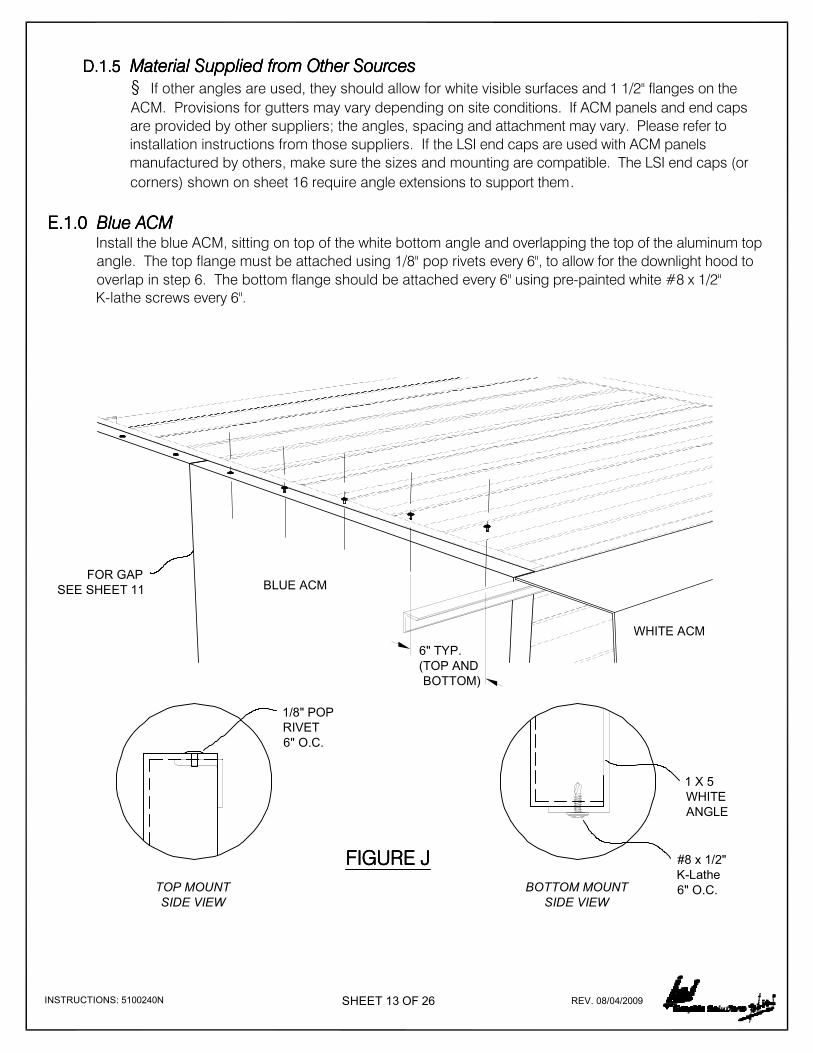
D.1.5 D.1.5 D.1.5 D.1.5 Material Supplied from Other SourcesMaterial Supplied from Other SourcesMaterial Supplied from Other SourcesMaterial Supplied from Other Sources
§ If other angles are used, they should allow for white visible surfaces and 1 1/2" flanges on the
ACM. Provisions for gutters may vary depending on site conditions. If ACM panels and end caps
are provided by other suppliers; the angles, spacing and attachment may vary. Please refer to
installation instructions from those suppliers. If the LSI end caps are used with ACM panels
manufactured by others, make sure the sizes and mounting are compatible. The LSI end caps (or
corners) shown on sheet 16 require angle extensions to support them.
E.1.0 E.1.0 E.1.0 E.1.0 Blue ACM Blue ACM Blue ACM Blue ACMInstall the blue ACM, sitting on top of the white bottom angle and overlapping the top of the aluminum top
angle. The top flange must be attached using 1/8" pop rivets every 6", to allow for the downlight hood to
overlap in step 6. The bottom flange should be attached every 6" using pre-painted white #8 x 1/2"
K-lathe screws every 6".
6" TYP.
(TOP AND
BOTTOM)
BOTTOM MOUNT
SIDE VIEW
TOP MOUNT
SIDE VIEW
FIGURE JFIGURE JFIGURE JFIGURE J
1/8" POP
RIVET
6" O.C.
#8 x 1/2"
K-Lathe
6" O.C.
BLUE ACM
WHITE ACM
1 X 5
WHITE
ANGLE
FOR GAP
SEE SHEET 11

E.1.1 E.1.1 E.1.1 E.1.1 Short panel at WordmarkShort panel at WordmarkShort panel at WordmarkShort panel at WordmarkThe Chevron guidelines call for a short panel to be installed at the end where a Wordmark is to be
mounted, so that no seams in the ACM panel fall within the channel letters. For the 42" fascia, this
panel is 29 1/2" long, for the 36" fascia this panel is 17" long. Begin at the end that will receive the
Wordmark, and install the short panel, and then 12ft. panels until the other end is reached. The
design intent is for the fascia to end with another short panel. If this guideline is followed, install the
short panel at the other end and measure the remaining gap. Cut and route a 12ft. panel to fit. (Note
that the panels have a route and return on the left side to allow for gaps between panels for thermal
expansion, and to allow for adjustments for leveling canopies. See Section E.1.3 for detail.)
SHEET 14 OF 26INSTRUCTIONS: 5100240O REV. 08/04/2009
144"
(12'-0")
29.5"
(2'-5 1/2")
42"
(3'-6") FIELD CUT
144"
(12'-0")
36"
(3'-0")
17"
(1'-5")
FIELD
CUT
E.1.2 E.1.2 E.1.2 E.1.2 Extra Panel SupportExtra Panel SupportExtra Panel SupportExtra Panel SupportIf structure is present, a screw can be placed in the left side flange of the panels for extra support, as
long as the screw does not interfere with the overlap of the next panel.
29.5"
(2'-5 1/2")
17"
(1'-5")
FIGURE KFIGURE KFIGURE KFIGURE K
FIGURE LFIGURE LFIGURE LFIGURE L
FIGURE MFIGURE MFIGURE MFIGURE M
ACM
FLANGE
TEK SCREW
6"
CEN TO CEN
42" FASCIA
36" FASCIA
FIELD CUT
FIELD
CUT
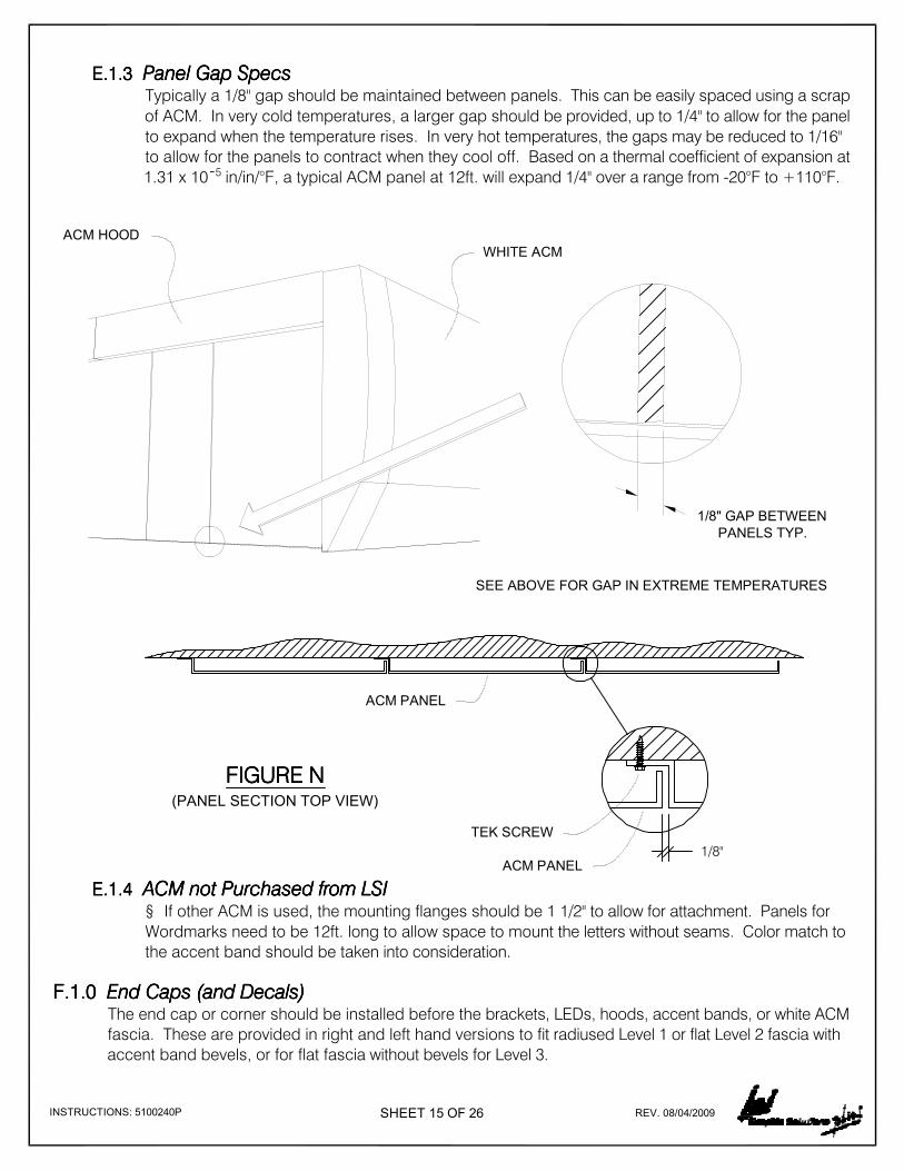
E.1.3 E.1.3 E.1.3 E.1.3 Panel Gap SpecsPanel Gap SpecsPanel Gap SpecsPanel Gap SpecsTypically a 1/8" gap should be maintained between panels. This can be easily spaced using a scrap
of ACM. In very cold temperatures, a larger gap should be provided, up to 1/4" to allow for the panel
to expand when the temperature rises. In very hot temperatures, the gaps may be reduced to 1/16"
to allow for the panels to contract when they cool off. Based on a thermal coefficient of expansion at
1.31 x 10¯ in/in/°F, a typical ACM panel at 12ft. will expand 1/4" over a range from -20°F to +110°F.
SHEET 15 OF 26INSTRUCTIONS: 5100240P REV. 08/04/2009
E.1.4 E.1.4 E.1.4 E.1.4 ACM not Purchased from LSIACM not Purchased from LSIACM not Purchased from LSIACM not Purchased from LSI§ If other ACM is used, the mounting flanges should be 1 1/2" to allow for attachment. Panels for
Wordmarks need to be 12ft. long to allow space to mount the letters without seams. Color match to
the accent band should be taken into consideration.
F.1.0 F.1.0 F.1.0 F.1.0 End Caps (and Decals) End Caps (and Decals) End Caps (and Decals) End Caps (and Decals)The end cap or corner should be installed before the brackets, LEDs, hoods, accent bands, or white ACM
fascia. These are provided in right and left hand versions to fit radiused Level 1 or flat Level 2 fascia with
accent band bevels, or for flat fascia without bevels for Level 3.
5
FIGURE NFIGURE NFIGURE NFIGURE N
1/8"
1/8" GAP BETWEEN
PANELS TYP.
ACM HOOD
SEE ABOVE FOR GAP IN EXTREME TEMPERATURES
WHITE ACM
TEK SCREW
ACM PANEL
ACM PANEL
(PANEL SECTION TOP VIEW)

SHEET 16 OF 26INSTRUCTIONS: 5100240Q REV. 08/04/2009
F.1.1 F.1.1 F.1.1 F.1.1 End Cap SizesEnd Cap SizesEnd Cap SizesEnd Cap SizesThese are also provided both as full 8" x 8" corners where illuminated fascia meets illuminated accent
band, or as 6" x 8" flush corners where illuminated accent band meets non-illuminated flat fascia. All
of the variations are provided in 42" and 36" heights standard. Other heights can be field cut or
custom sized and can be quoted through LSI Customer Service.
FIGURE OFIGURE OFIGURE OFIGURE O FIGURE PFIGURE PFIGURE PFIGURE PSTRAIGHT END CAPS
42"
36"
42"
36"42"
36"
8"
6 1/2"
42"
36"
8"8"
RADIUSED END CAPS
LEVEL 2 CANOPYLEVEL 1 CANOPY
8"
6 1/2"8"8"
FIGURE QFIGURE QFIGURE QFIGURE Q
1 1/2"
1"
5"
8"
*THE ANGLE LEG DIRECTLY ABOVE IS SHOWING
HOW IT IS CUT TO FIT INSIDE THE END CAPS.
#8 X 1/2" WHITE
K-LATHE SCREW
TOP AND BOTTOM
F.1.2 F.1.2 F.1.2 F.1.2 Illuminated Downlight to Illuminated AccentIlluminated Downlight to Illuminated AccentIlluminated Downlight to Illuminated AccentIlluminated Downlight to Illuminated AccentAs discussed in Section D.1.1, end caps require extended mounting angles to attach for Level 1 and 2
Canopies where illuminated downlight fascia meets illuminated accent band return. The 8" x 8" end
cap or corner will overlap the blue fascia by 1 1/2", and extend 6 1/2" beyond the white return side at
the top. The end cap should rest on the white angle below and slide over the aluminum angle at top,
attaching with (2) #8 x 1/2" white K-Lathe screws at the top and (2) #8 x 1/2" white K-Lathe screws at
the bottom. Optionally, a screw can be run from the back of the canopy through the blue ACM into the
1 1/2" flange return on the white end cap, or a double stick tape or adhesive can be used to attach this
flange.

SHEET 17 OF 26INSTRUCTIONS: 5100240R REV. 08/04/2009
F.1.3 F.1.3 F.1.3 F.1.3 Illuminated Accent to Non-Illuminated Blue FasciaIlluminated Accent to Non-Illuminated Blue FasciaIlluminated Accent to Non-Illuminated Blue FasciaIlluminated Accent to Non-Illuminated Blue FasciaFor Level 1 or 2 Canopies where an illuminated accent band meets a non-illuminated blue fascia, a 6
1/2" x 8" end cap or corner is used. (As discussed in Section F.1.0) This will mount flush to the blue
fascia, attaching to the angles on the return using the same white K-Lathe screws top and bottom as
for the 8" square corner. These flush corners are designed to be used with a printed decal to
simulate the downlight hood on the blue fascia.
F.1.4 F.1.4 F.1.4 F.1.4 Illuminated Downlight to Non-Illuminated AccentIlluminated Downlight to Non-Illuminated AccentIlluminated Downlight to Non-Illuminated AccentIlluminated Downlight to Non-Illuminated AccentFor Level 1 or 2 Canopies where an illuminated downlight fascia meets a non-illuminated accent
band return, or for Level 3 canopies, a square 8" x 8" end cap or corner without bevel is used. Similar
to the 6 1/2" x 8" corner, this end cap will mount flush to the white return and attach to the blue ACM
fascia top and bottom. Short 7 1/2" sections of mounting angle are required for mounting these
corners. The white ACM return should overlap the blue ACM fascia to avoid a blue edge showing on
the return. A printed decal can be used simulate the illuminated accent band on the white return.
FIGURE RFIGURE RFIGURE RFIGURE R
FIGURE SFIGURE SFIGURE SFIGURE S
NON-ILLUMINATED FASCIA
(FLAT WITH DECAL)6 1/2" x 8" END CAP
7.5" MOUNTING ANGLE
8" x 8" SQUARE END CAP
ILLUMINATED DOWNLIGHTER HOOD
ACCENT BAND
DECAL

SHEET 18 OF 26INSTRUCTIONS: 5100240S REV. 08/04/2009
F.1.5 F.1.5 F.1.5 F.1.5 Non-Illuminated CornerNon-Illuminated CornerNon-Illuminated CornerNon-Illuminated CornerOn non-illuminated sides, either a simulated downlight hood or a simulated accent band decal is
applied. The ACM surface, or other substrate, must be clean and sound, with no flaking or peeling,
and preferably no dents or fasteners. The decal is best applied over a smooth surface for maximum
effect and durability. Follow the instructions provided with the decals to apply these.
G.1.0 G.1.0 G.1.0 G.1.0 Downlight Fascia LED Brackets Downlight Fascia LED Brackets Downlight Fascia LED Brackets Downlight Fascia LED BracketsWith end caps or corners in place, the next step for the downlight blue fascia is to install the brackets for
the LED system and hood. One bracket should be installed flush to the end cap or corner at each end.
G.1.1 G.1.1 G.1.1 G.1.1 Downlight Bracket SizesDownlight Bracket SizesDownlight Bracket SizesDownlight Bracket SizesThe downlight bracket for the 36" fascia is 6 3/8" x 7 7/8". The downlight bracket for the 42" fascia is 7
7/8" x 7 7/8". Both are 2" at their narrowest point with 1 1/2" flanges folded for attachment to the ACM
and to support the LED assembly. The brackets are fabricated from .080 aluminum 5052 alloy with a
tensile strength of 31,000 psi minimum.
7 7/8"
7 7/8"
2"
30 3/4"
TYP
SPACING
G.1.2G.1.2G.1.2G.1.2 Downlight Bracket SpecsDownlight Bracket SpecsDownlight Bracket SpecsDownlight Bracket SpecsThe downlight bracket has been empirically tested to support 620 lbs of distributed load (equivalent
of 100 psf snowload or 120 mph wind) when attached to a 3mm ACM panel using #14 self drilling
stainless steel sheeting Tek screws (gasket head) in the holes provided 2 1/4" on center, with
brackets spaced 30 3/4" on center. The LED reflector assembly is pre-punched for 30 3/4" centers.
FIGURE VFIGURE VFIGURE VFIGURE V
ATTACH TO ACM PANEL
USING #14 SELF DRILLING
STAINLESS STEEL SHEETING
TEK SCREWS
36" FASCIA BRACKET
FIGURE TFIGURE TFIGURE TFIGURE T FIGURE UFIGURE UFIGURE UFIGURE U6 3/8"
7 7/8"
2" 42" FASCIA BRACKET
FOR INCREASED LOAD BEARING
STRENGTH, ADJUST BRACKET
SPACING AS SHOWN 15 3/8"
TYPICAL
SPACINGFIGURE WFIGURE WFIGURE WFIGURE W
G.1.3 G.1.3 G.1.3 G.1.3 Bracket WindloadBracket WindloadBracket WindloadBracket WindloadExcessive windloads (over 120mph) or heavy snowloads may cause buckling of the ACM, and
additional hat channel supports may be needed to support the weight. Additional brackets can be
added to meet higher load conditions. Placing brackets on 15 3/8" centers increases the load
bearing strength of the structure.

SHEET 19 OF 26INSTRUCTIONS: 5100240T REV. 08/04/2009
H.1.1H.1.1H.1.1H.1.1 Attaching the LED AssemblyAttaching the LED AssemblyAttaching the LED AssemblyAttaching the LED AssemblyBeginning at one end of the hood cavity, install the LED assembly using 1/8" rivets or #8 screws. DODODODO
NOTNOTNOTNOT attach through the holes in the LED pad. This will cause shorting of the LED. Attachment must
be made in the spaces between the LEDs.
Underwriters
Laboratories Inc.
UL
ELECTRICAL SIGN SECTION
No. AB 123456
SECTION OF
FEMALE
UL SECTIONAL
LABEL
WHITE (+)
SIDE VIEW
Underwriters
Laboratories Inc.
UL
ELECTRICAL SIGN SECTION
No. AB 123456
SECTION OF
MALE
FEMALEMALE
1/4" OVERLAP
H.1.2H.1.2H.1.2H.1.2 WiringWiringWiringWiringBe careful using drills or other power tools not to damage the LEDs or the connecting wires. The
female connector will be to the left and the male connector to the right as shown in the figure. Butt
the next section up to the reflector, or they may be overlapped 1/4". The male connector from one
assembly will snap into the female connector of the previous assembly. For illustration see Section
H.1.6 Figures AE and AF. Power cables will snap into the end as required based on wiring layouts.
Do not snap the ends together until the wiring has been determined.
FEMALEMALE
OPTION 1: BUTT SECTIONS TOGETHER OPTION 2: OVERLAP SECTIONS
FIGURE YFIGURE YFIGURE YFIGURE Y
FIGURE ZFIGURE ZFIGURE ZFIGURE Z FIGURE AAFIGURE AAFIGURE AAFIGURE AA
FIGURE XFIGURE XFIGURE XFIGURE X
H.1.0 H.1.0 H.1.0 H.1.0 LED Assembly LED Assembly LED Assembly LED AssemblyThe downlight LED assemblies are provided in 72" lengths, with 12 LEDs attached and male and female
connectors at the ends. Note the installation drawing showing the correct placement of the assembly.
This light is designed to fit inside an 8" x 8" hood over the blue ACM sides of the Chevron canopy. The
internal space must be a minimum of 6" x 6" as shown below, with attachment in the flat of the LED track at
a 17 degree angle ±2 degrees from horizontal. *If this angle is not correct, the wash lighting of the LED
will not be correct.
FEMALE(Start of Run)
LED TRACK (12 LEDs)
*LED ASSEMBLY BY LSI
3 5/8"
varies
9 1/2"
2"
1 1/2"
varies
2 1/8"17°
6"
WHITE ACM HOOD WRAPS
OVER TOP, DOWN THE
FRONT AND FOLDS UNDER
BLUE ACM FASCIA 36"
OR 42" HIGH BY OTHERS
NOTE:
BEFORE INSTALLING THE ACM HOOD,
IT IS EASIER TO INSTALL THE LEDs,
TRANSFORMER AND WIRING BEFORE
APPLYING THE HOOD.
TRANSFORMER
MOUNTING BRACKET BY LSI

SHEET 20 OF 26INSTRUCTIONS: 5100240U REV. 08/04/2009
H.1.4H.1.4H.1.4H.1.4 Power Supply SpecsPower Supply SpecsPower Supply SpecsPower Supply SpecsLSI provides power supplies to be used with these LED assemblies. These are provided as 60W
transformers. Each LED draws one watt, so up to 60 LEDs can be powered per circuit. Practically,
this means that five sections (60W or 30ft) of downlighter can be wired to each circuit, or it can power
up to three sections (60W or 22'-6") of the accent LEDs. A single 5ft male cable is provided with
these power supplies.
FIGURE AEFIGURE AEFIGURE AEFIGURE AE FIGURE AFFIGURE AFFIGURE AFFIGURE AF
H.1.5H.1.5H.1.5H.1.5 ConduitConduitConduitConduitEnclosure boxes and wiring bushings comply with NEC and UL requirements. The installer must
connect the provided seal-tite conduit to 120 VAC 60 Hz circuit in compliance with Article 600 of the
National Electrical code and/or other applicable codes. This includes proper grounding and bonding
of the sign.
H.1.6H.1.6H.1.6H.1.6 LED PowerLED PowerLED PowerLED PowerBoth the downlight and accent band use the same style power supply, but due to placement,
separate power supplies are used. The power supply for the downlighter can be mounted under the
hood, attached to the blue ACM, and serviced from below (See Detail AF). The power supply should
be mounted within four feet of the beginning of each run, and primary power supplied through the
ACM panel. Optionally, the power supply can be mounted on the back side of the ACM (See Detail
AG on sheet 21) or on the canopy structure within four feet of the connection. Due to space
constraints, the accent band power supply will not fit inside the cavity of the accent, and must be
mounted on the back side of the return or on the canopy structure. Be sure to keep the power
supply out of water accumulation areas, and to provide adequate protection for cables.
6'-0" (12 LEDs)
30'-0"
SEE FIGURE AE
FOR CONNECTION60W
TRANSFORMER
60W
TRANSFORMER
30'-0"
5ft CABLE TYP5ft CABLE TYP
SEE FIGURE AF
FOR CONNECTION
FIGURE AC (DOWNLIGHT)
END OF RUNFIGURE AD (DOWNLIGHT)
AT THE END OF A RUN
YOU MAY USE A 72" PIECE
OR 36" DEPENDING ON
SPACE AVAILABLE AND
CUT TO FIT.
NOTENOTENOTENOTE
ELECTRICIAN NEEDS THIS PAGE FOR WIRING.
SEE SHEET 23 FOR THE ACCENT DIAGRAMS.
MALE @ POWER
FEMALE @ LED
TRANSFORMER
TO SERVICE THE TRANSFORMER, IN EITHER THE ACCENT BAND OR THE
DOWNLIGHTER, YOU MUST UNFASTEN THE SCREWS AND REMOVE THE COVER.
TRANSFORMER
ACCENT DOWNLIGHT

SHEET 21 OF 26INSTRUCTIONS: 5100240V REV. 08/04/2009
J.1.0 J.1.0 J.1.0 J.1.0 ACM Hood ACM Hood ACM Hood ACM HoodOnce the support brackets are installed and the LED system has been mounted and wired, the white ACM
hood can be fitted over the assembly. The 42" fascia hood is 9 1/2" wide with an 8" vertical face and two 1
1/2" returns. The 36" fascia hood is identical except the vertical face is 6" instead of 8" tall. The ACM
panels are shipped pre-routed and notched to fold in the field.
9 1/2"
8" 1 1/2"
1 1/2"
9 1/2"
6"1 1/2"
FIGURE AHFIGURE AHFIGURE AHFIGURE AH FIGURE AIFIGURE AIFIGURE AIFIGURE AI
J.1.1 J.1.1 J.1.1 J.1.1 Bending the ACMBending the ACMBending the ACMBending the ACMUsing a bending tool available from LSI, or similar guide, bend the panels to the dimensions shown
in the details above. Note that the panels have a rout and return on the left side similar to the overlap
returns on the blue fascia panels.
J.1.2 J.1.2 J.1.2 J.1.2 Fastening the ACMFastening the ACMFastening the ACMFastening the ACMBeginning at the right hand side, overlapping the flange of the corner with an 1/8" gap, install the
hood panels over the brackets. Attach with a #8 x 1/2" white K-Lathe screw on the back side of the
bottom return, and to the top of the brackets using #10 x 1/2" gasketed screws to avoid leaks. (The
last 1 1/2" fold at the bottom of the hood can be left open to make installation easier and then folded
and secured in place.) The rear 1 1/2" of the hood should extend over the blue ACM fascia and
attach with another #10 x 1/2" gasketed screw every 6". The hood panels should overlap each other
as shown in the detail, with a nominal 1/8" space between panels. As in Section E.1.3, the width of
this gap should be varied depending on the air temperature at the time of installation, wider if
installing in cold weather, and smaller if installing in hot weather. (See sheet 22 for details)
1 1/2"
42" FASCIA HOOD FOLDED 36" FASCIA HOOD FOLDED
Note: If the power supply is mounted on the backside of the ACM, be sure to install vertically such that the
liquid-tite conduit is facing up as shown in the detail below.
SEAL-TITE CONDUIT
LOW VOLTAGE WIRE
SEAL-TITE CONDUIT
PROVIDED
BY THE INSTALLER
JUNCTION BOX
FIGURE AGFIGURE AGFIGURE AGFIGURE AG

SHEET 22 OF 26INSTRUCTIONS: 5100240W REV. 08/04/2009
K.1.0 K.1.0 K.1.0 K.1.0 Accent Band LED Brackets Accent Band LED Brackets Accent Band LED Brackets Accent Band LED BracketsWith the end caps and corners in place, the next step for the illuminated accent band return is to install the
mounting brackets for the LED accent system. One bracket should be mounted flush to each end of the
accent return spaced 12 7/8" from the bottom angle for 42" fascia and 10 7/8" from the bottom for 36"
fascia. Other sizes will require consultation with your Chevron Image Coordinator to determine
proportions.
K.1.1 K.1.1 K.1.1 K.1.1 Accent Bracket SizeAccent Bracket SizeAccent Bracket SizeAccent Bracket SizeThe accent bracket is roughly 6 3/4" tall x 6 7/16" wide, 3 3/4" at its narrowest point, with 1 1/2"
flanges folded for attachment to the ACM and to support the LED assembly. This bracket is
fabricated from .080 aluminum 5052 alloy with a tensile strength of 31,000psi minimum.
K.1.2 K.1.2 K.1.2 K.1.2 Accent Bracket SpecsAccent Bracket SpecsAccent Bracket SpecsAccent Bracket SpecsThe accent bracket has been empirically tested to support 100 lbs/sq.ft. for snowload and 55
lbs/sq.ft. when attached to a 16ga steel panel using #14 self drilling stainless steel sheeting Tek
screws (gasketed head) in the holes provided 2 3/4" on center, with brackets spaced 46 3/8" on
center.
FIGURE AKFIGURE AKFIGURE AKFIGURE AK
6 7/16"
6 3/4" FIGURE ALFIGURE ALFIGURE ALFIGURE AL
46 3/8"
TYPICAL
SPACINGATTACH TO ACM PANEL
USING #14 SELF DRILLING
SS SHEETING TEK SCREWS
FIGURE AMFIGURE AMFIGURE AMFIGURE AM
23 3/16" TYP
SPACING
K.1.3 K.1.3 K.1.3 K.1.3 WindloadWindloadWindloadWindloadExcessive windloads (over 100mph) or heavy snowloads may cause buckling of the substrate, and
additional hat channel supports may be needed to support the weight. Additional brackets can be
added to meet higher load conditions. Placing brackets on 23 3/16" centers increases the load
bearing strength of the structure.
6 1/16"
BLUE ACM FASCIA 36"
OR 42" HIGH BY OTHERS
FIGURE AJFIGURE AJFIGURE AJFIGURE AJ
START ATTACHING HOOD HERE
USING #10x1/2" GASKETED SCREW
FOLD HOOD
AROUND BRACKET
THE LAST 1-1/2" FLAP
CAN BE LEFT OPEN FOR
EASIER INSTALL UNTIL
READY TO ATTACHATTACH WITH
#8x1/2" K-LATHE

SHEET 23 OF 26INSTRUCTIONS: 5100240X REV. 08/04/2009
7'-6" (20 LEDs)
22'-6"
SEE FIGURE AE (SHT. 20)
FOR CONNECTION60W
TRANSFORMER
60W
TRANSFORMER
22'-6"
5ft CABLE TYP5ft CABLE TYP
SEE FIGURE AF (SHT. 20)
FOR CONNECTION
(ACCENT)
(ACCENT)END OF RUN
AT THE END OF A RUN YOU
MAY USE A 90" PIECE OR 36"
DEPENDING ON SPACE
AVAILABLE AND CUT TO FIT.
FIGURE AOFIGURE AOFIGURE AOFIGURE AO
FIGURE APFIGURE APFIGURE APFIGURE AP
MALE @ POWER
FEMALE @ LED
TO POWER BOXLED TO LED
LED TO LED CONNECTION
LED POWER CONNECTION
FEMALEMALE MALECONNECT THESE
TOGETHER (FEMALE)
THIS ONE IS NOT
CONNECTED (MALE)
FIGURE ANFIGURE ANFIGURE ANFIGURE AN
K.1.4 K.1.4 K.1.4 K.1.4 Accent LED AssemblyAccent LED AssemblyAccent LED AssemblyAccent LED AssemblyThe accent LED assemblies are provided in 90" lengths, with 20 LEDs attached and male and female
connectors at the ends. Note the installation drawing Figure AN showing the correct placement of
the assembly. Refer to sections H.1.1 and H.1.2 for attachment and wiring.
BLUE ACM ACCENT BAND
LED ASSEMBLY BY LSI
(20 LEDs)
CANOPY STRUCTURE
BY OTHERS
MOUNTING BRACKET BY LSI
WHITE ACM
(FLAT OR RADIUSED)
32" HIGH
8°
2 3 4"12 7 8"LED O.C.
10"
TRANSFORMER

SHEET 24 OF 26INSTRUCTIONS: 5100240Y REV. 08/04/2009
L.1.2 L.1.2 L.1.2 L.1.2 Level 2 CanopyLevel 2 CanopyLevel 2 CanopyLevel 2 CanopyLevel 2 Canopies have a flat return with beveled accent band, and these panels have a overlap route
and return similar to the blue fascia and white hood panel. Begin on the right and install with #10 x
1/2" gasketed screws to the top angle, and #8 x 1/2" white K-Lathe screws at the bottom. Gaps of
1/8" should be provided between panels, varied based on temperature as in section E.1.3 sheet 15.
As with Level 1, if there is to be a Hallmark logo installed where the field cut panel would fall, install a
full width panel and move the field cut panel over.
FIGURE ASFIGURE ASFIGURE ASFIGURE AS UNDERSIDE VIEW OF CANOPY
ACM END CAP
WHITE ACM RETURN
LED ACCENT BAND
LED DOWNLIGHT
FIXTURE
BLUE ACM FASCIA
LIT ACCENTLED DOWNLIGHTS
L.1.0 L.1.0 L.1.0 L.1.0 White ACM - Bullnose and Flat White ACM - Bullnose and Flat White ACM - Bullnose and Flat White ACM - Bullnose and FlatOnce the support brackets are installed and the LED system has been mounted and wired, the white ACM
return can be installed.
L.1.1 L.1.1 L.1.1 L.1.1 Level 1 CanopyLevel 1 CanopyLevel 1 CanopyLevel 1 CanopyLevel 1 Canopies have a radiused (or bullnose) return with beveled accent band. These panels are
rolled to the correct radius and have a tongue and groove joint that is factory applied. Begin at the
right and insert the tongue of the white ACM into the groove receiver in the end cap, leaving an 1/8"
gap, varied based on temperature as in section E.1.3 sheet 15. The panel will attach to the mounting
angle at the top and to the flange on bottom of the LED bracket, using #8 x 1/2" white K-Lathe
screws on bottom and #10 x 1/2" gasketed screws on top. The final panel must be cut to size, and
will overlap the the tongue extension on the left end cap. This joint may require adhesive or a small
white pop rivet to assure the radius fits and stays in place. If a Hallmark logo sign is to be mounted
on the left side on this return, the final panel should not be field cut. A full width 10ft. panel should be
installed, and the field cut panel placed to the right of the Hallmark.
FIGURE AQFIGURE AQFIGURE AQFIGURE AQ
XX X X
8"8"
EQ
25"
10"EQ
> 41" > 41"
EQ
EQ
25"
10"
FIGURE AQFIGURE AQFIGURE AQFIGURE AQBULLNOSED FACE RETURN UNDERSIDE VIEW OF CANOPY
RADIUSED
ACM END CAP
WHITE ACM RETURN
LED ACCENT BAND
LED DOWNLIGHT
FIXTURE
BLUE ACM FASCIA
LIT ACCENTLED DOWNLIGHTS

SHEET 25 OF 26INSTRUCTIONS: 5100240Z REV. 08/04/2009
M.1.0 M.1.0 M.1.0 M.1.0 Specification and Loading - Certifications Specification and Loading - Certifications Specification and Loading - Certifications Specification and Loading - Certifications
M.1.1 M.1.1 M.1.1 M.1.1 Fascia PanelsFascia PanelsFascia PanelsFascia PanelsAll fascia panels are fabricated from 3mm thick aluminumcomposite material, as manufactured by
Alcoa under the name Reynobon, or approved equivalents. These consist of two sheets of 0.02"
thick aluminum bonded to a thermoplastic core. The finish is approved Chevron Blue, reference PMS
2935C, or Chevron White, in a two part polymer resin finish with a twenty year warranty. The panels
weigh 0.94" lb/sft, and have a moment of inertia a 0.97 x 10 lb/in². The tensile yield strength is 8,300
lb/in² and the maximum allowable stress is 11,500 lb/in².
M.1.2 M.1.2 M.1.2 M.1.2 BracketsBracketsBracketsBracketsBrackets are fabricated from 0.08 aluminum alloy 5052 with tensile strength of 31,000 psi minimum.
These brackets have been tested to the equivalent of 100psf snowload and 120mph windload.
Actual installation will depend on fasteners, substrate and spacing of brackets, and should be
evaluated and certified by a professional engineer.
M.1.3 M.1.3 M.1.3 M.1.3 FastenersFastenersFastenersFastenersFasteners provided are Grade 2: stainless steel #10 x 1/2" gasketed (sheeting), zinc plated #12 x
3/4" Tek, and painted #10 x 1/2" K-Lathe self drilling screws. Rivets are painted aluminum with steel
mandrels.
L.1.3 L.1.3 L.1.3 L.1.3 Non-Illuminated ReturnsNon-Illuminated ReturnsNon-Illuminated ReturnsNon-Illuminated ReturnsNon-illuminated returns on Level 1 or 2 canopies, or all returns on Level 3, use flat white ACM with a
decal applied to simulate the accent band. These ACM panels install in the same manner as the
blue ACM for the downlight fascia shown in section E.1.0 sheet 13.
L.1.4 L.1.4 L.1.4 L.1.4 Level 4 and 5 CanopyLevel 4 and 5 CanopyLevel 4 and 5 CanopyLevel 4 and 5 CanopyLevel 4 and 5 canopies have all flat , non-illuminated ACM panels with decals applied.
UNDERSIDE VIEW OF CANOPY
ACM END CAP
WHITE ACM RETURN
LED ACCENT BAND
LED DOWNLIGHT
FIXTURE
BLUE ACM FASCIA
FIGURE ATFIGURE ATFIGURE ATFIGURE AT
UNDERSIDE VIEW OF CANOPY
WHITE ACM RETURN
VINYL ACCENT DECAL
VINYL HOOD DECAL
BLUE ACM FASCIA
FIGURE AUFIGURE AUFIGURE AUFIGURE AU
LED DOWNLIGHTS

SHEET 26 OF 26INSTRUCTIONS: 5100240AA REV. 08/04/2009
M.1.4 M.1.4 M.1.4 M.1.4 Engineer AssistanceEngineer AssistanceEngineer AssistanceEngineer AssistanceThe advice of a structural engineer may be required for some sites. LSI does not provide stamped
and sealed drawings. These should be contracted from a local professional engineer. LSI will
cooperate with these resources, or will quote evaluations on a site by site basis at an added cost .
M.1.5 M.1.5 M.1.5 M.1.5 LightingLightingLightingLightingThe LEDs, power sources and all components of the LSI Graphic Solutions Plus Chevron Image
Refresh LED downlight and accent band are UL recognized and LSI applies UL/CSA labels for
Sectional Signs under UL48 and our file E84811.
M.1.6 M.1.6 M.1.6 M.1.6 ComponentsComponentsComponentsComponentsThe components are recognized under the Sign and Accessories manual: LEDs as UL E213411,
power sources as E220165, wiring as E54567-LN, connectors as E29179, enclosures as 29Z9
E106319, conduit as E191011, and fittings as E190912.
M.1.7 M.1.7 M.1.7 M.1.7 Sectional SignsSectional SignsSectional SignsSectional SignsThe assembled sections and power supplies as we ship them out are labeled with our UL/C label as
Sectional Signs. This is listed under our file E84811. Since these are assembled on site, we must list
as sectional signs and include instructions for the installer to complete the assembly in the field. It
cannot be listed as a finished sign, as it is completed on site. An inspector from Underwriters
Laboratories checks production on a regular basis and approves this listing.
N.1.0 N.1.0 N.1.0 N.1.0 Energy Consumption Energy Consumption Energy Consumption Energy ConsumptionThe LED downlight system draws 2W/ft 12VDC, and the accent LED system draws 2.67W/ft at 12VDC.
System losses and cable lengths may result in higher actual power consumption. LEDs are a low energy
consumption lighting source, and as such may qualify for rebates and subsidies from governmental
agencies. The assembly is rated as a Class 2 low voltage lighting system.
P.1.0 P.1.0 P.1.0 P.1.0 Title 24 Title 24 Title 24 Title 24The California Energy Commission 2005 Building Energy Efficiency Standards, commonly referred to as
Title 24, mandates energy efficiency standards for residential and non-residential buildings, including
gasoline canopies under 6.6.3 of the Nonresidential Compliance Manual. Light Emitting Diodes (LEDs)
are a technology encouraged by this standard, as as such, the LSI LED Downlight and Accent Band for
Chevron is a response to addressing these needs. The downlight and accent band may be a contributor
to meeting your requirements for allowable lighting power allowances. Thses calculations are site specific
and the required forms must be completed by the Architect or Engineer of record, or their designee under
the California Business and Professions Code. LSI can not provide calculations or statements of
compliance with Title 24, but we will work with your design professionals to provide any information to
assist them in completing OLTGC-2-C.
If you have any further questions, please contact LSI Chevron Customer Service.
QQQQ.1.0 .1.0 .1.0 .1.0 Shortages or Freight Damage Claims Shortages or Freight Damage Claims Shortages or Freight Damage Claims Shortages or Freight Damage ClaimsAll shortages must be reported to LSI Graphic Solutions Plus within seven days after receipt of
material. Inspect shipment before letting the carrier leave. Buyer is responsible for placing claim
against the damage or lost goods during shipment. Products damaged during shipment require a
freight claim to be filed with freight carrier within seven days of receipt of goods on site. Freight
damaged goods are not covered under SGI's warranty .