Introduction to VLSI Design Program Cheng-Hwa Cheng Apr., 26, 2004.

Cheng Fluid Systems, Inc. is located in Mountain View, California. It was formed in October
of 1990 to develop, patent, and market Fluid Flow Conditioning Devices & Solutions.
Cheng Fluid Systems, Inc. holds the patents for the Cheng Rotation Vane (CRV®) and Large
Angle Diffuser (LAD®). Due to their unique and fundamental nature, the CRV® and LAD®
have a significant market and a wide range of applications, from fuel systems in aircraft
and automobiles to large industrial and utility complexes, such as chemical processing,
power plants and water distribution utilities.
The value and effectiveness of the company's products have been proven in over 3,000
installations with over 1500 being used by Fortune 500 chemical, refining, and power
companies.
Founder/CEO: Dr. Dah Yu Cheng, has over 30 years of experience & recognition as a rocket scientist, inventor, plasma physicist, & aerodynamicist Products: Flow Conditioning Technology: CRV® Cheng Rotation Vane LAD® Large Angle Diffuser Market: Solved over 3,000 cases of Piping & Flow Problems for many Leading Fortune 500 Companies. Industries: Refineries Power Pump Oil Nuclear Automotive Mining Water Processing Gas Utility Complexes
CFS is dedicated to solving
our customer's fluid flow problems by using our technology and experience, along with our patented products, the Cheng Rotation Vane (CRV®) and Large Angle Diffuser (LAD®)
LAD®
Cheng Fluid Systems, Inc.
Cheng Fluid Systems, Inc. 480 San Antonio Road, Suite 120. Mountain View, CA 94040. 650-941-9290, www.chengfluid.com
Piping systems are the heart of any utility or process. Efficiency in these systems has
payback and allows total output
Any fluid that flows through elbows and sudden expansions will experience:
Turbulence Accelerated Flow Separation
Reverse Flow Pressure Loss Cavitation
Flashing Noise Vibration
The CRV® imparts to the fluid (gas or liquid) a gyroscopic motion, which counteracts the
elbow induced gyroscopic motion, & enables the fluid to negotiate the turn through the
elbow in a flat uniform flow across the entire cross sectional area of the pipe
This results in an even distribution of process fluid through any cross-section of the
elbow and transforms the elbow into the equivalent of a straight length of pipe, and
there is no additional pressure drop with the use of a CRV®
The LAD® consists of a series of overlapping, truncated cones, all with a common focal
point, which is located within the expansion and allows a uniform exit profile
A CRV® & LAD® installed close to: pumps, compressors, check valves, control valves, flow
measurement equipment, elbow erosion/noise, water hammer, condensers, exhaust
section, chemical processing, and heat exchangers, will have better performance results,
reliability/efficiency of any downstream equipment and will improve maintenance down
times & energy costs will be reduced
Cheng Fluid Systems, Inc. 480 San Antonio Road, Suite 120. Mountain View, CA 94040. 650-941-9290, www.chengfluid.com
Cheng Fluid Systems, Inc. www.chengfluid.com
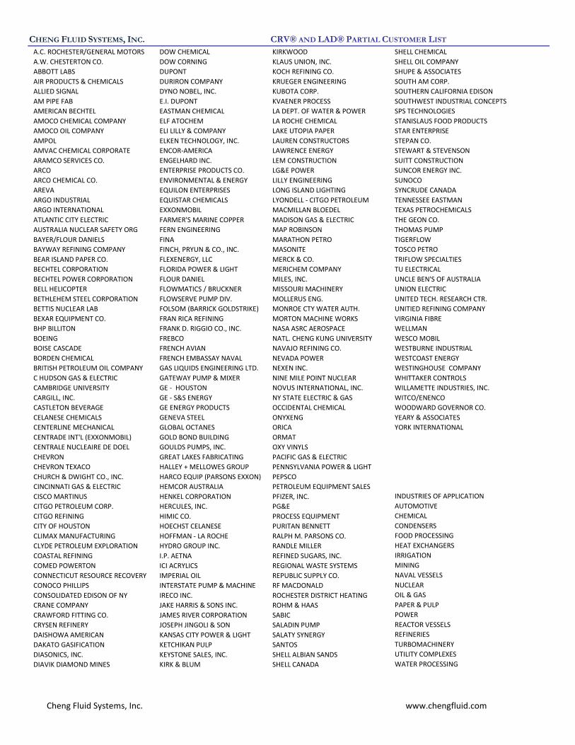
CHENG FLUID SYSTEMS, INC. CRV® AND LAD® PARTIAL CUSTOMER LIST
A.C. ROCHESTER/GENERAL MOTORS DOW CHEMICAL KIRKWOOD SHELL CHEMICAL
A.W. CHESTERTON CO. DOW CORNING KLAUS UNION, INC. SHELL OIL COMPANY
ABBOTT LABS DUPONT KOCH REFINING CO. SHUPE & ASSOCIATES
AIR PRODUCTS & CHEMICALS DURIRON COMPANY KRUEGER ENGINEERING SOUTH AM CORP.
ALLIED SIGNAL DYNO NOBEL, INC. KUBOTA CORP. SOUTHERN CALIFORNIA EDISON
AM PIPE FAB E.I. DUPONT KVAENER PROCESS SOUTHWEST INDUSTRIAL CONCEPTS
AMERICAN BECHTEL EASTMAN CHEMICAL LA DEPT. OF WATER & POWER SPS TECHNOLOGIES
AMOCO CHEMICAL COMPANY ELF ATOCHEM LA ROCHE CHEMICAL STANISLAUS FOOD PRODUCTS
AMOCO OIL COMPANY ELI LILLY & COMPANY LAKE UTOPIA PAPER STAR ENTERPRISE
AMPOL ELKEN TECHNOLOGY, INC. LAUREN CONSTRUCTORS STEPAN CO.
AMVAC CHEMICAL CORPORATE ENCOR-AMERICA LAWRENCE ENERGY STEWART & STEVENSON
ARAMCO SERVICES CO. ENGELHARD INC. LEM CONSTRUCTION SUITT CONSTRUCTION
ARCO ENTERPRISE PRODUCTS CO. LG&E POWER SUNCOR ENERGY INC.
ARCO CHEMICAL CO. ENVIRONMENTAL & ENERGY LILLY ENGINEERING SUNOCO
AREVA EQUILON ENTERPRISES LONG ISLAND LIGHTING SYNCRUDE CANADA
ARGO INDUSTRIAL EQUISTAR CHEMICALS LYONDELL - CITGO PETROLEUM TENNESSEE EASTMAN
ARGO INTERNATIONAL EXXONMOBIL MACMILLAN BLOEDEL TEXAS PETROCHEMICALS
ATLANTIC CITY ELECTRIC FARMER'S MARINE COPPER MADISON GAS & ELECTRIC THE GEON CO.
AUSTRALIA NUCLEAR SAFETY ORG FERN ENGINEERING MAP ROBINSON THOMAS PUMP
BAYER/FLOUR DANIELS FINA MARATHON PETRO TIGERFLOW
BAYWAY REFINING COMPANY FINCH, PRYUN & CO., INC. MASONITE TOSCO PETRO
BEAR ISLAND PAPER CO. FLEXENERGY, LLC MERCK & CO. TRIFLOW SPECIALTIES
BECHTEL CORPORATION FLORIDA POWER & LIGHT MERICHEM COMPANY TU ELECTRICAL
BECHTEL POWER CORPORATION FLOUR DANIEL MILES, INC. UNCLE BEN'S OF AUSTRALIA
BELL HELICOPTER FLOWMATICS / BRUCKNER MISSOURI MACHINERY UNION ELECTRIC
BETHLEHEM STEEL CORPORATION FLOWSERVE PUMP DIV. MOLLERUS ENG. UNITED TECH. RESEARCH CTR.
BETTIS NUCLEAR LAB FOLSOM (BARRICK GOLDSTRIKE) MONROE CTY WATER AUTH. UNITIED REFINING COMPANY
BEXAR EQUIPMENT CO. FRAN RICA REFINING MORTON MACHINE WORKS VIRGINIA FIBRE
BHP BILLITON FRANK D. RIGGIO CO., INC. NASA ASRC AEROSPACE WELLMAN
BOEING FREBCO NATL. CHENG KUNG UNIVERSITY WESCO MOBIL
BOISE CASCADE FRENCH AVIAN NAVAJO REFINING CO. WESTBURNE INDUSTRIAL
BORDEN CHEMICAL FRENCH EMBASSAY NAVAL NEVADA POWER WESTCOAST ENERGY
BRITISH PETROLEUM OIL COMPANY GAS LIQUIDS ENGINEERING LTD. NEXEN INC. WESTINGHOUSE COMPANY
C HUDSON GAS & ELECTRIC GATEWAY PUMP & MIXER NINE MILE POINT NUCLEAR WHITTAKER CONTROLS
CAMBRIDGE UNIVERSITY GE - HOUSTON NOVUS INTERNATIONAL, INC. WILLAMETTE INDUSTRIES, INC.
CARGILL, INC. GE - S&S ENERGY NY STATE ELECTRIC & GAS WITCO/ENENCO
CASTLETON BEVERAGE GE ENERGY PRODUCTS OCCIDENTAL CHEMICAL WOODWARD GOVERNOR CO.
CELANESE CHEMICALS GENEVA STEEL ONYXENG YEARY & ASSOCIATES
CENTERLINE MECHANICAL GLOBAL OCTANES ORICA YORK INTERNATIONAL
CENTRADE INT'L (EXXONMOBIL) GOLD BOND BUILDING ORMAT
CENTRALE NUCLEAIRE DE DOEL GOULDS PUMPS, INC. OXY VINYLS
CHEVRON GREAT LAKES FABRICATING PACIFIC GAS & ELECTRIC
CHEVRON TEXACO HALLEY + MELLOWES GROUP PENNSYLVANIA POWER & LIGHT
CHURCH & DWIGHT CO., INC. HARCO EQUIP (PARSONS EXXON) PEPSCO
CINCINNATI GAS & ELECTRIC HEMCOR AUSTRALIA PETROLEUM EQUIPMENT SALES
CISCO MARTINUS HENKEL CORPORATION PFIZER, INC. INDUSTRIES OF APPLICATION
CITGO PETROLEUM CORP. HERCULES, INC. PG&E AUTOMOTIVE
CITGO REFINING HIMIC CO. PROCESS EQUIPMENT CHEMICAL
CITY OF HOUSTON HOECHST CELANESE PURITAN BENNETT CONDENSERS
CLIMAX MANUFACTURING HOFFMAN - LA ROCHE RALPH M. PARSONS CO. FOOD PROCESSING
CLYDE PETROLEUM EXPLORATION HYDRO GROUP INC. RANDLE MILLER HEAT EXCHANGERS
COASTAL REFINING I.P. AETNA REFINED SUGARS, INC. IRRIGATION
COMED POWERTON ICI ACRYLICS REGIONAL WASTE SYSTEMS MINING
CONNECTICUT RESOURCE RECOVERY IMPERIAL OIL REPUBLIC SUPPLY CO. NAVAL VESSELS
CONOCO PHILLIPS INTERSTATE PUMP & MACHINE RF MACDONALD NUCLEAR
CONSOLIDATED EDISON OF NY IRECO INC. ROCHESTER DISTRICT HEATING OIL & GAS
CRANE COMPANY JAKE HARRIS & SONS INC. ROHM & HAAS PAPER & PULP
CRAWFORD FITTING CO. JAMES RIVER CORPORATION SABIC POWER
CRYSEN REFINERY JOSEPH JINGOLI & SON SALADIN PUMP REACTOR VESSELS
DAISHOWA AMERICAN KANSAS CITY POWER & LIGHT SALATY SYNERGY REFINERIES
DAKATO GASIFICATION KETCHIKAN PULP SANTOS TURBOMACHINERY
DIASONICS, INC. KEYSTONE SALES, INC. SHELL ALBIAN SANDS UTILITY COMPLEXES
DIAVIK DIAMOND MINES KIRK & BLUM SHELL CANADA WATER PROCESSING

Cheng Fluid Systems, Inc. www.chengfluid.com
The Cheng Rotation Vane (CRV®) consists of a set of stationary vanes in a cylindrical body, which is placed immediately
upstream of an elbow or tee in a piping system. The device addresses the following flow problems:
A. Pump Cavitation
B. Flow Measurement Accuracy
C. Elbow Erosion
D. Compressors
E. Check Valves
F. Water Hammer
The CRV® eliminates elbow induced turbulence which negatively impacts the performance of pumps, compressors, control
valves, flow meters, and other equipment. The CRV® inputs to the flow a counteracting gyroscopic motion to the resultant
elbow induced gyroscopic motion, and enable the fluid to negotiate the turn through the elbow and then exit the elbow with
a flat velocity profile. This results in an even distribution of process fluid through any cross-section of the elbow and
transforms the elbow into the equivalent of a straight length of pipe, and there is no additional pressure drop with the use of
a CRV®.
Flow through a plain elbow is illustrated in the Figure 1 (a-left). As a result of the forces acting on the fluid as it passes
through the elbow, two flow separation regions result where a void or vapor space is created. Because of the existence of
these flow separation regions, the remaining pipe cross-sectional area through which the fluid must pass is significantly
reduced, as shown in Figure 1 (b-left), and the local velocity is increased and directed towards the outer wall of the elbow.
This high velocity region is one of the reasons why elbows exhibit high-pressure drop as compared to a straight pipe.
Measured velocity profiles of the fluid downstream of a plain elbow at six locations are shown in Figure 1(c-left). As expected
for a plain elbow, Figure 1 (c-left) shows that there is a high velocity region in the straight section of pipe along the outside of
the elbow, and a low velocity/backflow region in the straight section of pipe along the inside of the elbow.
When the CRV® is placed immediately upstream of an elbow, it rotates the flow entering the elbow. As a consequence, the
fluid negotiates the turn with all the streamlines travelling approximately the same distance (equal flow path lengths) from
CRV® Operating Principle
Figure 1- In a plain elbow
(left), a skewed velocity
profile results. With a CRV®
mounted in front of the
elbow (right), there is a flat
velocity profile.

Cheng Fluid Systems, Inc. www.chengfluid.com
entrance to exit, as illustrated in Figure 1(a-right), and the flow separation regions are eliminated. The entire pipe cross-
sectional area is available for fluid flow as shown in Figure 1(b-right). For this reason, the total drop in pressure in a CRV®–
plus-elbow-combination is 25% to 50% less than that of a plain elbow without a CRV®. In Figure 1(c-right), the measured
velocity profile with a CRV® becomes relatively flat at the elbow exit and almost perfectly flat at a downstream position of
L/D=1.25.
Flow separation and the rotational effect of the CRV® are also shown in Figures 2(a) and 2(b) where the use of different
colored dyes trace the flow streamlines in a transparent 6-inch diameter short radius elbow carting water. In Figure 2(a), the
dyes follow the elbow streamlines and the inner and outer flow separation regions can be seen along with exit turbulence. In
Figure 2(b) where the dyes are injected at the end of the CRV® (beginning of the elbow), the dye streamlines rotate 180-
degrees, as does the fluid itself, producing equal fluid flow path lengths around the elbow exit. The blade angle of a CRV® is
uniquely designed to match each elbow’s geometry and flow path length.
Using computational fluid dynamics modeling, one can reproduce, in Figure 3, the laboratory-measured velocity profiles of
Figure 1(c). The plain elbow velocity profile is shown in Figure 3(a)-left and illustrates the high velocity along the outer wall of
the elbow and the low/backflow velocity along the inner wall of the elbow. Figure 3(b)-left shows the velocity profile of the
cross -sectional area at the end of the simulation. Figure 3(a)-right and 3(b)-right show the same simulation with a CRV®
directly in the front of the elbow. Note the dramatic flattening of the velocity profile and the resultant elimination of flow
separation/backflow regions.
Figure 2- When water flows
through an elbow (a), flow
becomes turbulent. With a
CRV® upstream of the elbow,
the fluid negotiates the turn
(b) with all streamlines
travelling equal flow paths.
Figure 3- Computational fluid
dynamics modeling illustrates
elbow fluid dynamics without
(left) and with a CRV®(right)

Cheng Fluid Systems, Inc. www.chengfluid.com
Did You Know That...
95% of All Pumps Cavitate to a Certain Degree.
95% of all Industrial Explosions, Fires, Leaks, Etc. are caused by Eroding Pipe Elbows, Leaking Pumps, & Control Valves.
95% of All of These Problems could be prevented by Using Cheng Fluid System's Experience, Technology, & Patented Products.
Cheng Fluid Systems has solved over 3,000 Cases of Piping and Flow Problems for the Leading Fortune 500
Companies in the Chemical, Industrial, & Power Industries. In piping and flow systems, when fluids move through pipe fittings such as elbows, tees, U-joints, manifolds, and sudden expansions the fluid becomes turbulent, causing noise, vibration, cavitation, separation, and accelerated and reverse flows. If these pipe fittings are used next to pumps, flow meters, compressors, control valves, and process equipment, the equipment will experience failures with unscheduled downtimes, lost or reduced production, excessive repair costs, loss of flow, head, and efficiency, safety concerns, environmental spills, clean-up costs, inaccurate measurements, erratic control, non-uniform flow, increased energy costs, and the need for more space for proper installation. These problems are not the fault of the equipment, but are caused by your processing pipe and fittings. If you are experiencing these fluid flow problems, then you need the help of Cheng Fluid Systems’ experience, knowledge and technology to solve them. The following pages address the CRV® flow conditioning solution of various applications/problems: •Pump flanged right up to an elbow In a major power plant a pump cavitated and had to be repaired every three months. A CRV® was placed in the line and the pump has not been repaired for three years. •Elbow erosion In a major refinery the blow down catalyst eroded through an elbow once a month. A CRV® was placed in the line and the elbow has not been replaced since (4 years). •Measurement Application In a major natural gas transmission pipeline an orifice meter required 30 pipe diameters of pipe length for accurate measurement. A CRV® was placed in the line and the pipe length requirement was reduced to three diameters. •Control valve applications A major gas turbine manufacturer was losing efficiency. A CRV® was installed before the control valves and the efficiency increased.
CRV® Applications & Solutions

Cheng Fluid Systems, Inc. www.chengfluid.com
Pumps
Problem: -Pump Cavitation, Flow Separation, Vibration, Noise -Frequent seal bearing or impeller replacement -Non-uniform suction flow creating reduced flow -Lack of space for proper pump installation
Since all centrifugal pumps require well-developed inlet flow to meet their potential, a pump may not perform or be as reliable as expected due to a faulty suction piping layout such as a close-coupled elbow on the inlet flange.
When poorly developed flow enters the pump impeller, it strikes the vanes and is unable to follow the impeller passage. The liquid then separates from the vanes causing mechanical problems due to cavitation, vibration and performance problems due to turbulence and poor filling of the impeller. This results in premature seal, bearing and impeller failure, high maintenance costs, high power consumption, and less-than-specified head and/or flow.
In many instances, pump purchasers buy the least expensive pump that will deliver the specified flow and head within the NPSH available. Such a pump with high suction specific speed operating at 3,600 rpm or greater requires a well developed, uniform flow pattern at a narrow flow rate range since the impeller inlet eye and vanes are optimized to not create turbulence at design flow. This pump design feature is very susceptible to non-uniform inlet flow because when liquid velocity varies and does not meet the pump design assumption of a uniform velocity striking the impeller eye, flow separation results which causes cavitation and associated problems.
To have a well-developed flow pattern, pump manufacturer's manuals recommend about 10 diameters of straight pipe run upstream of the pump inlet flange. Unfortunately, piping designers and plant personnel must contend with space and equipment layout constraints and usually cannot comply with this recommendation. Instead, it is common to use an elbow close-coupled to the pump suction which creates a poorly developed flow pattern at the pump suction.
Benefits: -Reduced maintenance intervals & less downtime -Reduced cavitation, vibration & noise -Improved net positive suction head (NPSH) -Safer work environment - Higher reliability with less energy consumption -Increased pump efficiency and head
Solution: The CRV®
With a double-suction pump tied to a close-coupled elbow, flow distribution to the impeller is poor and causes reliability and performance shortfalls. The elbow divides the flow unevenly with more channeled to the outside of the elbow. Consequently, one side of the double-suction impeller receives more flow at a higher velocity and pressure while the starved side receives a highly turbulent and potentially damaging flow. This degrades overall pump performance (delivered head, flow and power consumption) and causes axial imbalance which shortens seal, bearing and impeller life.
By imparting a swirl to the flow entering the elbow, the CRV® enables the liquid to negotiate the turn and be evenly distributed to each side of the impeller. With the CRV®, flow and characteristics will approach factory rated pump test performance, cavitation and noise will diminish seal, bearing, and impeller life will improve.
The CRV® compensates for specification and installation constraints and attacks the root cause of poor pump performance due to faulty suction piping layout. With CRV® installation, pump performance and reliability will be maintained despite close-couple elbows on pump suctions, even when applied in high suction specific speed and double suction pumps.

Cheng Fluid Systems, Inc. www.chengfluid.com
Compressors
Problem: -Interstage hunting from non-uniform flow -Inlet flow distortion causing less than factory rated flow, head and efficiency
Centrifugal and axial compressor operation and performance are sensitive to velocity and mass distribution at the suction, just as pumps and other rotating equipment. When a compressor's factory performance test is run, the ASME Power Test Code (PTC-10) requires a fully developed uniform velocity and mass flow profile entering the compressor. To accomplish this, PTC-10 states two requirements.
First, a minimum straight run of three pipes diameters is required between the last elbow and compressor inlet.
Second, a flow equalizer is required at the straight pipe inlet to produce a flat velocity profile and assure an even distribution of gas into the compressor inlet.
Benefits: -Operate closer to factory rated flow, head & efficiency -Reduced suction piping pressure drop and reduced energy costs
Solution: The CRV®
In field operations, however, compressors do not have this ideal suction piping configuration. Poor field suction piping includes single, double, and triple elbows immediately upstream of of the compressor, which create a considerable amount of distortion. For example, large multistage axial or centrifugal compressors that are used to supply air for refinery fluid catalytic cracking units, as shown above, have upstream turns in the air suction piping which results in non-uniform mass and flow profiles approaching the splitter in the compressor casing.
The CRV® when placed on the inlet side of an elbow produces a flat velocity profile and an even distribution of process gas at the elbow’s exit. This allows the compressor to more closely approach its factory test inlet conditions and performance curves. Typical CRV® locations in compressor feed piping systems are shown below and for multistage externally-cooled compressors below.

Cheng Fluid Systems, Inc. www.chengfluid.com
Flow Meter
Problem: -Inaccurate flow measurements -Long straight pipe meter runs required -Lack of space for proper installation
Flow metering devices cannot provide accurate measurement of the flow rate through a pipe when flow entering the measurement device is distorted. Consequently, flow meter manufactures and a number of independent organizations such as ASME, AGA and ANSI/API recommend that flow meters not be installed near and downstream of elbows.
For example, when an orifice meter with a Beta ratio of 0.7 is used and the flow meter is preceded by two elbows in one plane, example A shows that the American Gas Association (AGA) recommends a minimum of 19 pipe diameters of straight pipe be used between the last elbow and the flow meter. Conventional after-elbow-straightening vanes example B, only decrease the recommended straight pipe length between the last elbow and the flow meter to 12 pipe diameters. However, the use of CRV® upstream of the elbow in example C, decreases the recommended straight pipe length between the last elbow and the flow meter to 2 diameters.
Benefits: -Accurate flow measurements -More compact pipe layout -Reduced piping costs
Solution: The CRV®
With the CRV® one can reduce the straight pipe run length for an orifice plate flow meter preceded by elbows as seen below.
In places where less than the recommended straight pipe meter run exists, installation of a CRV® will result in more accurate measurements. For example, dramatic improvements were witnessed in a 10”-diameter flow meter application where the installation of a CRV® decreased the meter error from 30% to less than 5%.
In new Installations, the CRV® allows the close coupling of flow meter to elbows, which results in space savings and reducing straight-run piping costs.

Cheng Fluid Systems, Inc. www.chengfluid.com
Elbow Erosion
Problem: -Frequent elbow erosion due to particulate or two-phase flow
-Unsafe elbow erosion conditions -Unscheduled maintenance shutdowns
Erosion commonly occurs in elbows and turns within
piping systems. Damage often occurs when the pipe
line is carrying solid particulates, slurries, or two
phase flow, such as wet steam. In a plain elbow, the
flow is accelerated and directed toward the outer wall
of the elbow, which focuses high speed particulates
or droplets on a restricted region. Severe wear begins
to occur at that point.
Installing a CRV® upstream of an elbow eliminates
flow separation and creates a smooth aerodynamic
flow with its vanes to ensure full rotation of all
components in the fluid as a solid body around the
turn. As a result, particulates and droplets are carried
along with the flow much the same as in a straight
piece of pipe, which shows little erosion in the same
service. In addition, the entire cross-sectional area of
the elbow is available for flow and the maximum fluid
velocity reached is much lower than in a plain elbow.
The CRV® vanes aerodynamic design, as shown
below, eliminates erosion of the CRV® itself in gas-
liquid, two-phase flow applications. In slurry or gas-
particulate applications, the CRV® can be hardened,
surface treated or manufactured in an appropriate
material whose hardness is greater than that of the
particulates.
Benefits: -Extended life of elbows -Safer and better operating and maintenance conditions -Safer work environment -Less down-time
Solution: The CRV®
Case History 1: A case history involving the installation of a total of six CRV®s, one upstream of each of six 2” extra
heavy pipe elbows for wet steam service in a paper mill, prove successful operation for more than two years after
installation. Previously, elbow replacement was required every 3 months.
Case History 2: Fluid catalytic cracking units (FCCU) in refineries have also successfully used the CRV® on spent
catalyst blowdown lines. Here, a total of four specially hardened CRV®s were installed in the FCCU 12” diameter
piping systems, one in front of each 90⁰ and 180⁰ turn, which eliminated the erosion experienced every 6 months in
the sweep elbows .

Cheng Fluid Systems, Inc. www.chengfluid.com
Check Valves
Problem: -Check valve chatter with close coupled upstream elbows
-Disc pin wear and breakage -Poor sealing due to pin wear
Check valves, by the very nature of their design, respond to flow and pressure disturbances such as turbulence in the upstream piping system. This can result in the disc oscillating back and forth on the pin support. When a check valve is close-coupled to an upstream elbow, the turbulence becomes severe and the oscillations are of a large enough amplitude that the disc continually moves, may bang against the stop, and the pin eventually fails.
In check valve systems with upstream close-coupled elbows, one can eliminate harmful high amplitude pressure bursts (a) by installing a CRV® (b) upstream of the elbow.
Benefits: -Eliminate elbow induced flow turbulence -Extend pin life -Improve sealing life
Solution: The CRV®
Experimental results of check valve dynamics with and without a CRV® are shown. Figure (a) shows pressure measurements as a function of time with the elbow-check valve combination only (Without the CRV®). The high amplitude pressure bursts are damaging to the check valve and a result of the oscillating check valve disc and the turbulence generated by the elbow.
With a CRV® mounted in front of the elbow-check valve combination, turbulence generated by the elbow is eliminated. Figure (b) shows an absence of high amplitude pressure bursts. This results in minimized wear on check valve pins, extended life, reduced vibration and noise, and better sealing because or pin integrity.

Cheng Fluid Systems, Inc. www.chengfluid.com
Water Hammer
Problem: -Travelling pressure wave reflecting back and forth in piping system
-Pipe and elbow breakage
Water hammer is actually a traveling pressure wave.
It was initiated by the rapid stoppage of an
incompressible flowing liquid. For example, the
pounding of process piping usually occurs due to
rapid valve closure or when large steam bubbles are
introduced into water and the water rapidly collapses
the steam bubbles. These pressure waves reflect
back-and-forth between the interior walls of a piping
system, reinforcing themselves as succeeding waves
encounter the reflected waves. They can become so
energetic that catastrophic structural damage could
occur.
The CRV® proves extremely useful in controlling water
hammer. Dramatic improvements were seen in a
piping circuit with four elbows between the supply
line and the shut-off valve where the wall static
pressure with and without CRV®s was measured. The
results indicate that with a CRV® in place upstream of
each elbow, the amplitude of the peak pressure pulse
was 49% of that without CRV®s.
The CRV®s geometric features prove extremely useful
in controlling water hammer. When fluid is flowing in
the forward direction, the CRV® is passive and offers
little pressure drop, but when the fluid travels
backwards, it will exhibit a high pressure drop and not
remain attached to the CRV® vanes, as shown below
in figure (a(. The high drag footprint for backward
flowing fluid and pressure waves is shown below in
figure (b), and acts as a passive damper for reverse
flow pressure waves, thus controlling water hammer.
Benefits: -Minimize pipe damage using CRV® as a passive damper for pressure waves
-Extended life of elbows and pipes
Solution: The CRV®

Cheng Fluid Systems, Inc. www.chengfluid.com
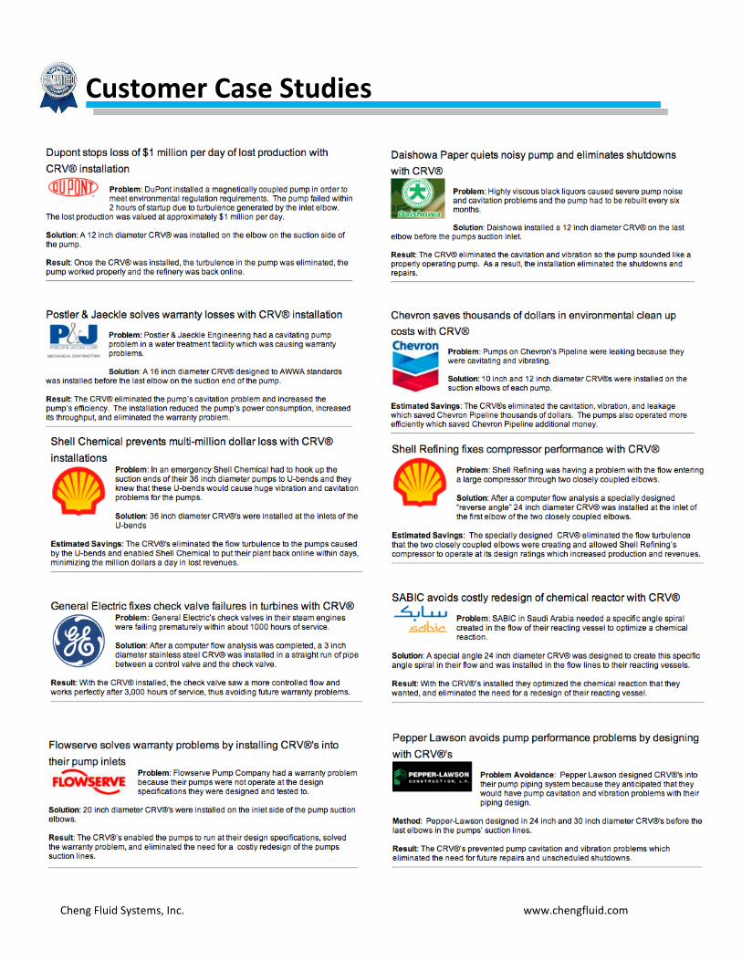
Customer Case Studies
Cheng Fluid Systems, Inc. www.chengfluid.com
Customer Case Studies

Cheng Fluid Systems, Inc. www.chengfluid.com
Availability: The highly adaptable CRV® and LAD® are manufactured in most commercially available materials of construction, pipe diameters, housing schedules and end connections. Special coatings and finishes may also be specified i.e. Boron coating for strengthening. Specifying a Flow Conditioner: For the convenience of engineers, architects and contractors in writing CRV® and LAD® specifications, please reference the diagrams provided below.
Dimensions: LAD®- Fits into any size concentric expansion or reduction. CRV®- Standard unit dimensions in 2-12" sizes are shown in Table 1 below. If a shorter CRV® is required, it can be custom manufactured upon request. Pipe Fitting Geometry: When specifying a CRV®, it is critical that the CRV® matches the geometry of the fitting to which it will be attached. The fitting schedule (wall thickness) and type of fitting must be specified. For example, fitting types are shown in fugure 11-15 and are available in both short and long radius. In order to assist you in proper specification of your fitting, the following nomenclature and dimensions are noted for common fittings in Table 2.
*Cheng Fluid Systems, Inc. Reserves the right to modify dimensions, materials, or design to ensure ideal performance of CRV®.
CRV® & LAD® Design & Installation

Cheng Fluid Systems, Inc. www.chengfluid.com
Cheng Fluid Systems, Inc. 480 San Antonio Road, Suite 120. Mountain View, CA 94040. Phone: (650) 941-9290. Website: www.chengfluid.com
We are pleased to receive your inquiry for use of our CRV® product. Our CRV® and LAD® products are custom made to specifically address each piping issue offering the greatest achievable flow correction. Please fill in the form below for a quote request. You may email additional information and drawings to [email protected].
Name Date
Company Title
Street City & State
E-mail Telephone
Application Data
Pump: Mfg./Model____________ NPSH Avail./Req’d_______ RPM__________________
Condenser Cooling Circuit
Elbow Erosion
Water hammer
Compressor
Vibration
Flow Meter
Check Valve
Noise
Other
Flow Conditions Fluid Type _________________________________ Flow Rate _________________________________ Temperature _________________________________ Pressure _________________________________ Other, please specify _________________________________
Mechanical Data Piping Diameter/Schedule ___________________________ Materials of Construction ___________________________ Elbow Geometry:
45⁰
90⁰
180⁰
Tee
Other______
Long Radius
Short Radius
Miter
Other______
The CRV® is supplied as a pipe stub with internal welded vanes. The pipe stub is approximately one diameter long with buttweld ends; Flanges are optional.
Description of Problem ______________________________________________________________________________________________________________________________________________________________________________________________________________________________________________________________________________________________________________________________________________________________________________________________________________________________________________________________________________________________________________________________________________________________________________ Isometric installation sketch showing upstream elbows, piping system diameters, lengths, and other inline equipment such as meters, valves, strainers, tee’s, expanders, etc.