Chemical anchoring systems. - Hilti · Chemical anchoring systems 59 ... Hilti HVU adhesive may be...
202
July 2014 page 59 Chemical anchoring systems. Foil capsule systems l Injection mortar systems
Transcript of Chemical anchoring systems. - Hilti · Chemical anchoring systems 59 ... Hilti HVU adhesive may be...
July 2014 page 59
Chemical anchoring systems.
Foil capsule systems l Injection mortar systems
Contents
Contents
Chemical anchoring systems 59
HVU with HAS/HAS-E rod adhesive anchor 60
HVU with HIS-(R)N adhesive anchor 72
HIT-HY 200 with HIT-V 84
HIT-HY 200 with HIS-(R)N 102
HIT-HY 200 with HIT-Z 120
HIT-HY 200 with rebar 138
HIT-RE 500 with HIT-V / HAS in hammer drilled holes 152
HIT-RE 500 with HIT-V / HAS in diamond drilled holes 166
HIT-RE 500 with rebar in hammer drilled holes 180
HIT-RE 500 with rebar in diamond drilled holes 192
HIT-RE 500-SD with HIT-V 202
HIT-RE 500-SD with rebar 216
HIT-HY 110 with HIT-V / HAS 226
HIT-HY 110 with HIS-(R)N 240
HIT-HY 70 injection mortar for masonry 252
Chemical anchor components & accessories 264
page 60 July 2014
HVU with HAS-E rod adhesive anchor
CE conformity
Small edge distance
& spacing
European Technical Approval
Concrete
A4 316
Corrosion resistance
HCR highMo
High corrosion resistance
HVU with HAS-E rod adhesive anchor
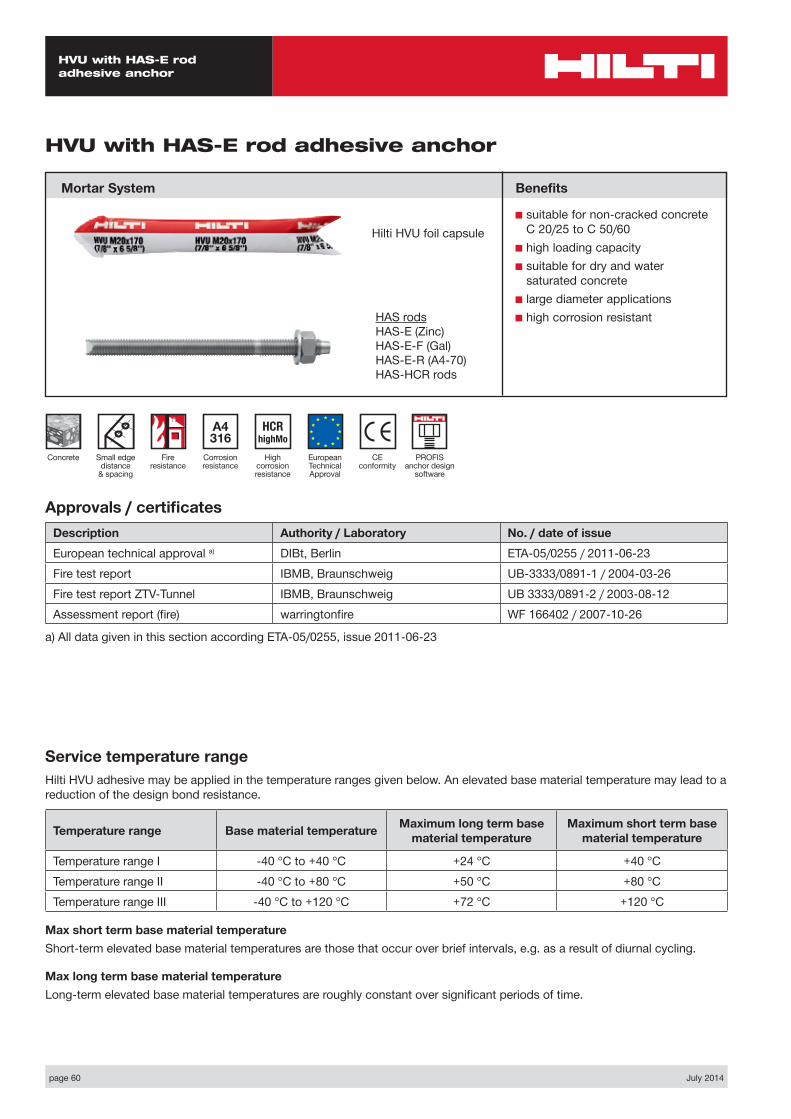
Mortar System
Approvals / certificatesDescription Authority / Laboratory No. / date of issueEuropean technical approval a) DIBt, Berlin ETA-05/0255 / 2011-06-23Fire test report IBMB, Braunschweig UB-3333/0891-1 / 2004-03-26Fire test report ZTV-Tunnel IBMB, Braunschweig UB 3333/0891-2 / 2003-08-12Assessment report (fire) warringtonfire WF 166402 / 2007-10-26
a) All data given in this section according ETA-05/0255, issue 2011-06-23
Service temperature rangeHilti HVU adhesive may be applied in the temperature ranges given below. An elevated base material temperature may lead to a reduction of the design bond resistance.
Temperature range Base material temperature Maximum long term base material temperature
Maximum short term base material temperature
Temperature range I -40 °C to +40 °C +24 °C +40 °CTemperature range II -40 °C to +80 °C +50 °C +80 °CTemperature range III -40 °C to +120 °C +72 °C +120 °C
Max short term base material temperatureShort-term elevated base material temperatures are those that occur over brief intervals, e.g. as a result of diurnal cycling.
Max long term base material temperatureLong-term elevated base material temperatures are roughly constant over significant periods of time.
Benefits
■ suitable for non-cracked concrete C 20/25 to C 50/60
■ high loading capacity■ suitable for dry and water
saturated concrete■ large diameter applications■ high corrosion resistant
Fire resistance
Hilti HVU foil capsule
PROFIS anchor design
software
HAS rodsHAS-E (Zinc)HAS-E-F (Gal)HAS-E-R (A4-70)HAS-HCR rods
July 2014 page 61
HVU with HAS-E rod adhesive anchor
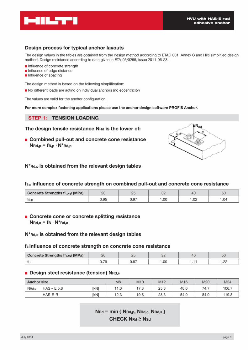
Design process for typical anchor layoutsThe design values in the tables are obtained from the design method according to ETAG 001, Annex C and Hilti simplified design method. Design resistance according to data given in ETA-05/0255, issue 2011-06-23.■ Influence of concrete strength ■ Influence of edge distance ■ Influence of spacing
The design method is based on the following simplification:■ No different loads are acting on individual anchors (no eccentricity)
The values are valid for the anchor configuration.
For more complex fastening applications please use the anchor design software PROFIS Anchor.
STEP 1: TENSION LOADING
The design tensile resistance NRd is the lower of:
■ Combined pull-out and concrete cone resistance NRd,p = fB,p • N*Rd,p
N*Rd,p is obtained from the relevant design tables
fB,p influence of concrete strength on combined pull-out and concrete cone resistance
Concrete Strengths f’c,cyl (MPa) 20 25 32 40 50fB,p 0.95 0.97 1.00 1.02 1.04
■ Concrete cone or concrete splitting resistance NRd,c = fB • N*Rd,c
N*Rd,c is obtained from the relevant design tables
fB influence of concrete strength on concrete cone resistance
Concrete Strengths f’c,cyl (MPa) 20 25 32 40 50fB 0.79 0.87 1.00 1.11 1.22
■ Design steel resistance (tension) NRd,s
Anchor size M8 M10 M12 M16 M20 M24NRd,s HAS – E 5.8 [kN] 11.3 17.3 25.3 48.0 74.7 106.7
HAS-E-R [kN] 12.3 19.8 28.3 54.0 84.0 119.8
NRd = min { NRd,p, NRd,c, NRd,s } CHECK NRd ≥ NSd
page 62 July 2014
HVU with HAS-E rod adhesive anchor
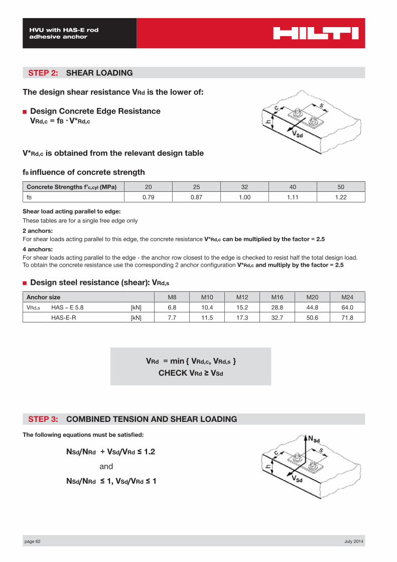
STEP 2: SHEAR LOADING
The design shear resistance VRd is the lower of:
■ Design Concrete Edge Resistance VRd,c = fB • V*Rd,c
V*Rd,c is obtained from the relevant design table
fB influence of concrete strength
Concrete Strengths f’c,cyl (MPa) 20 25 32 40 50fB 0.79 0.87 1.00 1.11 1.22
Shear load acting parallel to edge:These tables are for a single free edge only2 anchors:For shear loads acting parallel to this edge, the concrete resistance V*Rd,c can be multiplied by the factor = 2.54 anchors:For shear loads acting parallel to the edge - the anchor row closest to the edge is checked to resist half the total design load. To obtain the concrete resistance use the corresponding 2 anchor configuration V*Rd,c and multiply by the factor = 2.5
■ Design steel resistance (shear): VRd,s
Anchor size M8 M10 M12 M16 M20 M24VRd,s HAS – E 5.8 [kN] 6.8 10.4 15.2 28.8 44.8 64.0
HAS-E-R [kN] 7.7 11.5 17.3 32.7 50.6 71.8
STEP 3: COMBINED TENSION AND SHEAR LOADING
The following equations must be satisfied:
NSd/NRd + VSd/VRd ≤ 1.2
and
NSd/NRd ≤ 1, VSd/VRd ≤ 1
VRd = min { VRd,c, VRd,s } CHECK VRd ≥ VSd
July 2014 page 63
HVU with HAS-E rod adhesive anchor
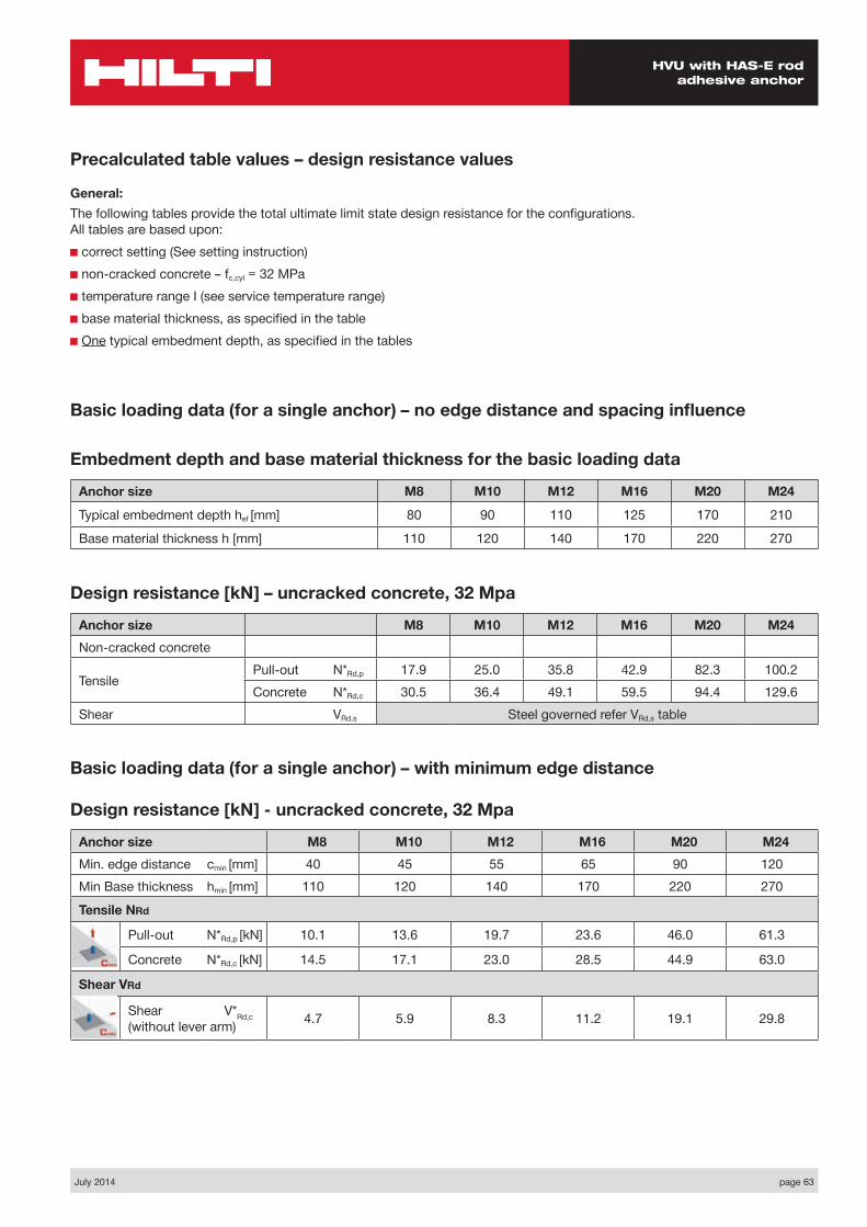
Basic loading data (for a single anchor) – no edge distance and spacing influence
Embedment depth and base material thickness for the basic loading data
Anchor size M8 M10 M12 M16 M20 M24
Typical embedment depth hef [mm] 80 90 110 125 170 210
Base material thickness h [mm] 110 120 140 170 220 270
Precalculated table values – design resistance values
General:The following tables provide the total ultimate limit state design resistance for the configurations. All tables are based upon:■ correct setting (See setting instruction)■ non-cracked concrete – fc,cyl = 32 MPa■ temperature range I (see service temperature range)■ base material thickness, as specified in the table■ One typical embedment depth, as specified in the tables
Design resistance [kN] – uncracked concrete, 32 Mpa
Anchor size M8 M10 M12 M16 M20 M24Non-cracked concrete
Tensile Pull-out N*Rd,p 17.9 25.0 35.8 42.9 82.3 100.2Concrete N*Rd,c 30.5 36.4 49.1 59.5 94.4 129.6
Shear VRd,s Steel governed refer VRd,s table
Basic loading data (for a single anchor) – with minimum edge distance
Design resistance [kN] - uncracked concrete, 32 Mpa
Anchor size M8 M10 M12 M16 M20 M24Min. edge distance cmin [mm] 40 45 55 65 90 120Min Base thickness hmin [mm] 110 120 140 170 220 270
Tensile NRd
Pull-out N*Rd,p [kN] 10.1 13.6 19.7 23.6 46.0 61.3
Concrete N*Rd,c [kN] 14.5 17.1 23.0 28.5 44.9 63.0
Shear VRd
Shear V*Rd,c (without lever arm) 4.7 5.9 8.3 11.2 19.1 29.8

page 64 July 2014
HVU with HAS-E rod adhesive anchor
Nsd
Vsd
S1
C
h
Two anchors Table 1: One edge influence
Design Data: fc,cyl=32 MPa
Anchor size M8 M10 M12 M16 M20 M24Typical embedment depth hef [mm] 80 90 110 125 170 210
Base material thickness h [mm] 110 120 140 170 220 270
ANCHOR
M8Edge C (mm)
40 80 100 150 170spacings1 (mm)
tension shear tension shear tension shear tension shear tension shearN*Rd,p N*Rd,c V*Rrd,c N*Rd,p N*Rd,c V*Rrd,c N*Rd,p N*Rd,c V*Rrd,c N*Rd,p N*Rd,c V*Rrd,c N*Rd,p N*Rd,c V*Rrd,c
40 13.6 16.2 6.3 19.9 21.1 13.1 23.5 23.7 15.4 24.1 30.9 21.0 24.1 34.1 23.2
80 15.3 17.9 7.9 22.3 23.3 15.0 26.3 26.2 17.2 27.0 34.2 22.7 27.0 37.6 24.9
100 16.1 18.8 8.7 23.5 24.4 15.9 27.7 27.4 18.1 28.4 35.8 23.6 28.4 39.4 25.8
120 16.9 19.6 9.4 24.7 25.5 16.9 29.1 28.7 19.0 29.8 37.4 24.5 29.8 41.2 26.6
150 18.1 20.9 9.4 26.5 27.2 18.3 31.2 30.6 20.4 31.9 39.9 25.7 31.9 43.9 27.9
200 20.0 23.0 9.4 29.3 29.9 20.6 34.5 33.7 22.7 35.4 43.9 27.9 35.4 48.4 30.0
ANCHOR
M10Edge C (mm)
45 80 100 150 200spacings1 (mm)
tension shear tension shear tension shear tension shear tension shearN*Rd,p N*Rd,c V*Rrd,c N*Rd,p N*Rd,c V*Rrd,c N*Rd,p N*Rd,c V*Rrd,c N*Rd,p N*Rd,c V*Rrd,c N*Rd,p N*Rd,c V*Rrd,c
45 17.6 19.1 7.9 23.3 23.3 14.8 26.9 25.9 17.2 32.4 33.0 23.2 32.4 40.5 29.1
100 20.2 21.5 10.3 26.7 26.3 17.6 30.8 29.2 19.9 37.1 37.1 25.8 37.1 45.5 31.6
150 22.4 23.6 11.8 29.7 28.9 20.2 34.3 32.1 22.4 41.3 40.9 28.1 41.3 50.1 33.8
200 24.7 25.8 11.8 32.7 31.5 22.8 37.7 35.1 24.9 45.4 45.6 30.5 45.4 54.7 36.0
250 26.9 28.0 11.8 35.6 34.2 24.9 41.1 38.0 27.4 49.5 48.3 32.8 49.5 59.3 38.3
300 27.2 30.1 11.8 36.0 36.8 24.9 41.6 41.0 29.9 50.1 52.1 35.1 50.1 63.9 40.6
ANCHOR
M12Edge C (mm)
55 80 100 150 200spacings1 (mm)
tension shear tension shear tension shear tension shear tension shearN*Rd,p N*Rd,c V*Rrd,c N*Rd,p N*Rd,c V*Rrd,c N*Rd,p N*Rd,c V*Rrd,c N*Rd,p N*Rd,c V*Rrd,c N*Rd,p N*Rd,c V*Rrd,c
55 25.3 25.5 11.1 30.1 28.7 16.4 34.2 31.4 20.4 45.5 38.5 27.0 46.0 46.3 33.5
100 27.9 27.6 13.3 33.2 31.1 18.9 37.7 34.0 23.0 50.1 41.7 29.4 50.7 50.1 35.8
150 30.7 29.9 15.8 36.6 33.7 21.7 41.5 36.8 25.9 55.2 45.2 32.1 55.9 54.3 38.4
200 33.6 32.2 16.6 39.9 36.3 24.5 45.4 39.6 28.8 60.3 48.7 34.8 61.0 58.5 41.0
250 36.4 34.6 16.6 43.3 38.9 26.7 49.1 42.5 31.6 65.4 52.1 37.5 66.1 62.7 43.5
300 39.1 36.9 16.6 46.5 41.5 26.7 52.9 45.3 34.5 70.3 55.6 40.2 71.1 66.9 46.1
July 2014 page 65
HVU with HAS-E rod adhesive anchor
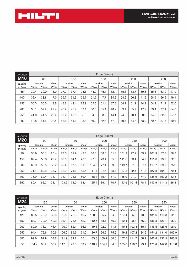
ANCHOR
M16Edge C (mm)
65 100 150 200 250spacings1 (mm)
tension shear tension shear tension shear tension shear tension shearN*Rd,p N*Rd,c V*Rrd,c N*Rd,p N*Rd,c V*Rrd,c N*Rd,p N*Rd,c V*Rrd,c N*Rd,p N*Rd,c V*Rrd,c N*Rd,p N*Rd,c V*Rrd,c
65 30.4 32.0 15.0 37.2 37.1 23.5 48.0 45.1 32.4 55.3 53.7 39.8 55.3 63.0 47.0
100 32.4 33.8 17.0 39.7 39.3 25.7 51.2 47.7 34.6 58.9 56.8 41.9 58.9 66.6 49.1
150 35.3 36.5 19.8 43.2 42.4 28.9 55.8 51.4 37.8 64.2 61.2 44.9 64.2 71.9 52.0
200 38.1 39.2 22.4 46.7 45.4 32.1 60.3 55.1 40.9 69.4 65.7 47.9 69.4 77.1 54.8
250 41.0 41.8 22.4 50.2 48.5 35.3 64.8 58.9 44.1 74.6 70.1 50.9 74.6 82.3 57.7
300 43.8 44.5 22.4 53.6 51.6 38.6 69.2 62.6 47.2 79.7 74.6 53.9 79.7 87.5 60.6
ANCHOR
M20Edge C (mm)
90 150 200 250 300spacings1 (mm)
tension shear tension shear tension shear tension shear tension shearN*Rd,p N*Rd,c V*Rrd,c N*Rd,p N*Rd,c V*Rrd,c N*Rd,p N*Rd,c V*Rrd,c N*Rd,p N*Rd,c V*Rrd,c N*Rd,p N*Rd,c V*Rrd,c
90 56.9 50.1 25.4 73.5 59.9 42.8 88.8 68.6 51.4 101.9 77.9 59.9 101.9 87.7 68.3
150 62.4 53.6 29.7 80.5 64.1 47.5 97.3 73.4 55.8 111.6 83.4 64.2 111.6 93.9 72.5
200 66.9 56.5 33.2 86.4 67.6 51.5 104.3 77.4 59.6 119.7 87.9 67.7 119.7 99.0 75.9
250 71.4 59.5 36.7 92.2 71.1 55.4 111.4 81.4 63.6 127.8 92.4 71.3 127.8 104.1 79.4
300 75.9 62.4 38.1 98.1 74.6 59.4 118.4 85.4 67.0 135.9 97.0 74.9 135.9 109.2 82.8
350 80.4 65.3 38.1 103.9 78.0 63.4 125.4 89.4 70.7 143.9 101.5 78.4 143.9 114.3 86.3
ANCHOR
M24Edge C (mm)
120 150 200 250 350spacings1 (mm)
tension shear tension shear tension shear tension shear tension shearN*Rd,p N*Rd,c V*Rrd,c N*Rd,p N*Rd,c V*Rrd,c N*Rd,p N*Rd,c V*Rrd,c N*Rd,p N*Rd,c V*Rrd,c N*Rd,p N*Rd,c V*Rrd,c
120 80.5 70.9 39.8 90.5 76.3 49.7 108.2 85.7 64.0 127.4 95.6 73.6 131.6 116.8 92.6
150 83.7 72.9 42.3 94.1 78.5 52.3 112.5 88.1 66.7 132.4 98.3 76.2 136.8 120.1 95.0
200 89.0 76.3 46.4 100.0 82.1 56.7 119.6 92.2 71.1 140.8 102.8 80.4 145.5 125.6 98.9
250 94.4 79.6 50.6 106.0 85.6 61.0 126.7 96.2 75.6 149.2 107.2 84.6 154.2 131.0 102.9
300 99.6 82.9 54.7 111.9 89.2 65.4 133.8 100.2 80.0 157.5 111.7 88.9 162.8 136.5 106.9
350 104.9 86.2 58.9 117.8 92.8 69.7 140.9 104.2 84.5 165.8 116.2 93.1 171.4 142.0 110.8

page 66 July 2014
HVU with HAS-E rod adhesive anchor
Four anchors Table 2: One edge influence
Design Data: fc,cyl=32 MPa
Anchor size M8 M10 M12 M16 M20 M24Typical embedment depth hef [mm] 80 90 110 125 170 210
Base material thickness h [mm] 110 120 140 170 220 270
Nsd
Vsd
S2
S1
C
h
ANCHOR
M8Edge C (mm)
40 80 100 150 200spacing
s1= s2 (mm)
tension shear tension shear tension shear tension shear tension shearN*Rd,p N*Rd,c V*Rrd,c N*Rd,p N*Rd,c V*Rrd,c N*Rd,p N*Rd,c V*Rrd,c N*Rd,p N*Rd,c V*Rrd,c N*Rd,p N*Rd,c V*Rrd,c
40 20.2 19.3 12.6 28.2 24.4 17.7 32.6 27.2 19.9 33.3 34.8 25.4 33.3 38.1 30.9
80 26.5 24.7 15.7 35.7 30.7 23.8 40.8 34.0 26.0 41.6 42.7 31.4 41.6 46.5 36.8
100 29.8 27.7 17.3 39.7 34.1 26.9 45.2 37.6 29.0 46.0 47.0 34.4 46.0 51.0 39.8
120 33.3 30.8 18.9 43.9 37.7 29.9 49.7 41.4 32.0 50.6 51.5 37.4 50.6 55.8 42.7
150 38.8 35.8 18.9 50.4 43.5 34.3 56.7 47.5 36.4 57.7 58.6 41.8 57.7 63.3 47.0
200 48.3 45.0 18.9 61.6 53.9 41.2 68.9 58.6 43.7 70.0 71.4 49.0 70.0 76.9 54.2
ANCHOR
M10Edge C (mm)
45 80 100 150 200spacing
s1= s2 (mm)
tension shear tension shear tension shear tension shear tension shearN*Rd,p N*Rd,c V*Rrd,c N*Rd,p N*Rd,c V*Rrd,c N*Rd,p N*Rd,c V*Rrd,c N*Rd,p N*Rd,c V*Rrd,c N*Rd,p N*Rd,c V*Rrd,c
45 17.3 22.6 15.7 32.1 27.1 20.2 36.5 29.9 22.6 43.1 37.3 28.5 43.1 45.1 34.3
100 34.6 30.3 20.6 42.9 35.7 29.2 48.1 39.0 31.6 56.0 47.8 37.3 56.0 57.0 43.0
150 44.2 38.2 23.6 54.0 44.5 37.2 60.0 48.3 39.5 69.1 58.5 45.1 69.1 69.1 50.8
200 54.7 47.0 23.6 65.9 54.2 45.0 72.8 58.6 47.3 83.1 70.2 52.9 83.1 82.4 58.4
250 65.9 56.7 23.6 78.6 64.9 49.8 86.4 69.9 54.8 98.0 83.1 60.5 98.0 96.8 66.0
300 67.5 67.3 23.6 80.4 76.6 49.8 88.3 82.2 59.8 100.2 97.0 68.1 100.2 112.3 73.6
ANCHOR
M12Edge C (mm)
55 80 100 150 200spacing
s1= s2 (mm)
tension shear tension shear tension shear tension shear t n shearN*Rd,p N*Rd,c V*Rrd,c N*Rd,p N*Rd,c V*Rrd,c N*Rd,p N*Rd,c V*Rrd,c N*Rd,p N*Rd,c V*Rrd,c N*Rd,p N*Rd,c V*Rrd,c
55 35.7 30.2 22.1 41.5 33.5 25.1 46.5 36.4 27.7 60.0 43.9 34.2 60.6 52.0 40.6
100 45.0 36.7 26.6 51.6 40.5 33.3 57.2 43.7 35.8 72.5 52.1 42.2 73.2 61.3 48.5
150 56.3 44.7 31.7 63.9 49.0 43.4 70.4 52.6 44.7 87.8 62.2 50.9 88.6 72.5 57.1
200 68.7 53.5 33.2 77.3 58.3 49.0 84.6 62.4 53.3 104.3 73.1 59.5 105.2 84.6 65.6
250 81.9 63.0 33.2 91.7 68.4 53.5 99.8 73.0 63.3 121.8 84.9 68.0 122.8 97.7 74.0
300 96.0 73.3 33.2 106.8 79.3 53.5 115.9 84.3 69.0 140.3 97.5 76.3 141.4 111.6 82.4

July 2014 page 67
HVU with HAS-E rod adhesive anchor
Shear design: The concrete edge resistance value in this table uses all 4 anchors in shear. You will need to ensure the gap between anchor and the plate is filled. This can be achieved using the Hilti Dynamic Set. (Refer page 41 for further details)
The concrete edge resistance values have been obtained by taking the lesser of:1. First row resistance multiplied by number of rows and 2. The concrete edge resistance of the furthest row.
ANCHOR
M16Edge C (mm)
65 100 150 200 250spacing
s1= s2 (mm)
tension shear tension shear tension shear tension shear tension shearN*Rd,p N*Rd,c V*Rrd,c N*Rd,p N*Rd,c V*Rrd,c N*Rd,p N*Rd,c V*Rrd,c N*Rd,p N*Rd,c V*Rrd,c N*Rd,p N*Rd,c V*Rrd,c
65 43.0 38.2 29.5 51.2 43.7 34.6 64.3 52.0 42.0 73.0 61.1 49.2 73.0 70.9 56.4
100 50.1 44.0 33.9 59.1 49.9 41.9 73.3 59.0 49.1 82.7 68.9 56.2 82.7 79.5 63.2
150 61.1 52.9 39.7 71.3 59.6 52.0 87.2 69.8 59.0 97.7 80.9 66.0 97.7 92.6 72.9
200 73.0 62.6 44.9 84.4 70.1 61.8 102.1 81.5 68.7 113.8 93.7 75.6 113.8 106.8 82.5
250 85.7 73.1 44.9 98.4 81.4 70.7 118.0 94.0 78.4 130.8 107.5 85.2 130.8 122.0 92.0
300 99.2 84.4 44.9 113.1 93.5 77.1 134.7 107.4 87.9 148.8 122.3 94.6 148.8 138.1 101.4
ANCHOR
M20Edge C (mm)
90 150 200 250 300spacing
s1= s2 (mm)
tension shear tension shear tension shear tension shear tension shearN*Rd,p N*Rd,c V*Rrd,c N*Rd,p N*Rd,c V*Rrd,c N*Rd,p N*Rd,c V*Rrd,c N*Rd,p N*Rd,c V*Rrd,c N*Rd,p N*Rd,c V*Rrd,c
90 76.6 59.6 47.9 95.7 70.0 58.2 113.1 79.2 66.6 127.9 89.0 75.0 127.9 99.3 83.3
150 94.8 70.6 59.3 116.6 82.1 72.5 136.4 92.3 80.7 153.1 103.1 88.9 153.1 114.4 97.0
200 111.4 80.4 66.4 135.5 92.9 84.1 157.4 103.9 92.2 175.8 115.6 100.3 175.8 127.9 108.3
250 129.2 90.8 73.5 155.8 104.3 95.5 179.8 116.3 103.5 200.0 128.9 111.5 200.0 142.1 119.5
300 148.2 101.9 76.3 177.3 116.4 106.7 203.6 129.3 114.7 225.7 142.8 122.6 225.7 157.1 130.5
350 168.4 113.5 76.3 200.2 129.2 117.9 228.8 143.0 125.8 252.8 157.5 133.6 252.8 172.8 141.5
ANCHOR
M24Edge C (mm)
120 150 200 250 350spacing
s1= s2 (mm)
tension shear tension shear tension shear tension shear tension shearN*Rd,p N*Rd,c V*Rrd,c N*Rd,p N*Rd,c V*Rrd,c N*Rd,p N*Rd,c V*Rrd,c N*Rd,p N*Rd,c V*Rrd,c N*Rd,p N*Rd,c V*Rrd,c
120 115.5 85.3 71.7 127.5 91.0 77.4 148.7 101.0 86.9 171.5 111.5 96.4 176.5 133.8 115.0
150 126.2 91.3 79.9 138.8 97.3 85.6 161.1 107.8 95.0 185.1 118.6 104.3 190.4 142.0 122.8
200 144.9 101.9 92.8 158.7 108.3 98.9 183.0 119.5 108.2 209.1 131.1 117.4 214.8 156.0 135.6
250 164.9 113.0 101.1 179.8 119.9 112.0 206.2 131.8 121.1 234.4 144.2 130.2 240.6 170.8 148.3
300 185.9 124.7 109.4 202.1 132.0 124.9 230.6 144.7 133.9 260.9 158.0 142.9 267.6 186.2 160.8
350 207.9 137.0 117.7 225.4 144.8 139.5 256.0 158.2 146.6 288.6 172.3 155.5 295.8 202.2 173.3
page 68 July 2014
HVU with HAS-E rod adhesive anchor
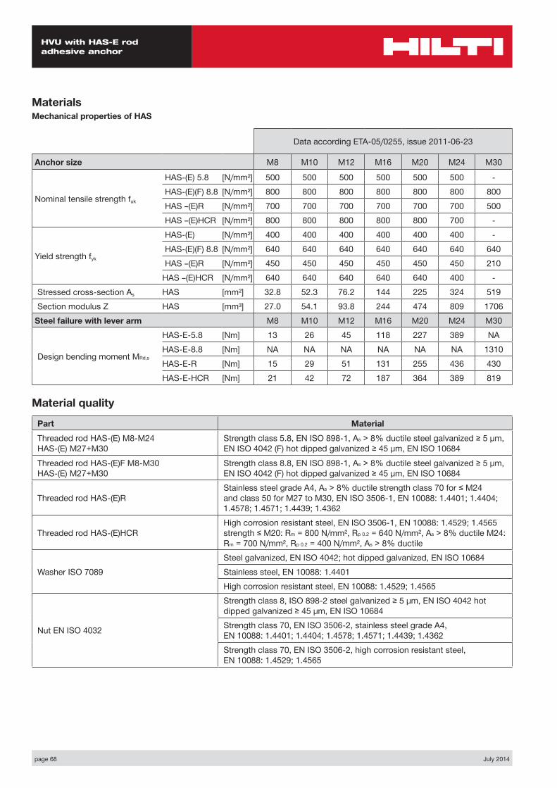
MaterialsMechanical properties of HAS
Data according ETA-05/0255, issue 2011-06-23
Anchor size M8 M10 M12 M16 M20 M24 M30
Nominal tensile strength fuk
HAS-(E) 5.8 [N/mm²] 500 500 500 500 500 500 -HAS-(E)(F) 8.8 [N/mm²] 800 800 800 800 800 800 800HAS –(E)R [N/mm²] 700 700 700 700 700 700 500HAS –(E)HCR [N/mm²] 800 800 800 800 800 700 -
Yield strength fyk
HAS-(E) [N/mm²] 400 400 400 400 400 400 -HAS-(E)(F) 8.8 [N/mm²] 640 640 640 640 640 640 640HAS –(E)R [N/mm²] 450 450 450 450 450 450 210
HAS –(E)HCR [N/mm²] 640 640 640 640 640 400 -Stressed cross-section As HAS [mm²] 32.8 52.3 76.2 144 225 324 519Section modulus Z HAS [mm³] 27.0 54.1 93.8 244 474 809 1706
Steel failure with lever arm M8 M10 M12 M16 M20 M24 M30
Design bending moment MRd,s
HAS-E-5.8 [Nm] 13 26 45 118 227 389 NAHAS-E-8.8 [Nm] NA NA NA NA NA NA 1310HAS-E-R [Nm] 15 29 51 131 255 436 430HAS-E-HCR [Nm] 21 42 72 187 364 389 819
Material quality
Part Material
Threaded rod HAS-(E) M8-M24 HAS-(E) M27+M30
Strength class 5.8, EN ISO 898-1, As > 8% ductile steel galvanized ≥ 5 µm, EN ISO 4042 (F) hot dipped galvanized ≥ 45 µm, EN ISO 10684
Threaded rod HAS-(E)F M8-M30 HAS-(E) M27+M30
Strength class 8.8, EN ISO 898-1, As > 8% ductile steel galvanized ≥ 5 µm, EN ISO 4042 (F) hot dipped galvanized ≥ 45 µm, EN ISO 10684
Threaded rod HAS-(E)RStainless steel grade A4, As > 8% ductile strength class 70 for ≤ M24 and class 50 for M27 to M30, EN ISO 3506-1, EN 10088: 1.4401; 1.4404; 1.4578; 1.4571; 1.4439; 1.4362
Threaded rod HAS-(E)HCRHigh corrosion resistant steel, EN ISO 3506-1, EN 10088: 1.4529; 1.4565 strength ≤ M20: Rm = 800 N/mm², Rp 0.2 = 640 N/mm², As > 8% ductile M24: Rm = 700 N/mm², Rp 0.2 = 400 N/mm², As > 8% ductile
Washer ISO 7089Steel galvanized, EN ISO 4042; hot dipped galvanized, EN ISO 10684Stainless steel, EN 10088: 1.4401High corrosion resistant steel, EN 10088: 1.4529; 1.4565
Nut EN ISO 4032
Strength class 8, ISO 898-2 steel galvanized ≥ 5 µm, EN ISO 4042 hot dipped galvanized ≥ 45 µm, EN ISO 10684Strength class 70, EN ISO 3506-2, stainless steel grade A4, EN 10088: 1.4401; 1.4404; 1.4578; 1.4571; 1.4439; 1.4362Strength class 70, EN ISO 3506-2, high corrosion resistant steel, EN 10088: 1.4529; 1.4565
July 2014 page 69
HVU with HAS-E rod adhesive anchor
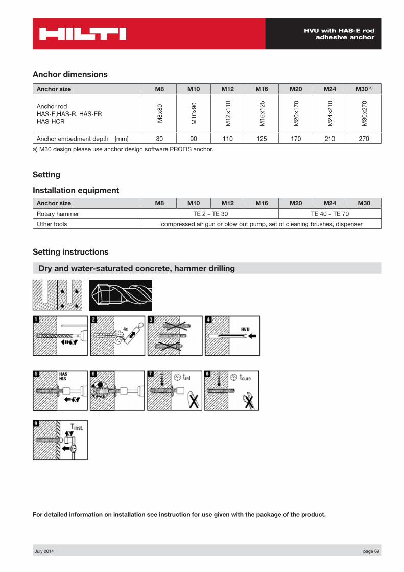
Anchor dimensions
Anchor size M8 M10 M12 M16 M20 M24 M30 a)
Anchor rod HAS-E,HAS-R, HAS-ER HAS-HCR M
8x80
M10
x90
M12
x110
M16
x125
M20
x170
M24
x210
M30
x270
Anchor embedment depth [mm] 80 90 110 125 170 210 270a) M30 design please use anchor design software PROFIS anchor.
Setting
Installation equipmentAnchor size M8 M10 M12 M16 M20 M24 M30Rotary hammer TE 2 – TE 30 TE 40 – TE 70Other tools compressed air gun or blow out pump, set of cleaning brushes, dispenser
Setting instructions
Dry and water-saturated concrete, hammer drilling
For detailed information on installation see instruction for use given with the package of the product.
page 70 July 2014
HVU with HAS-E rod adhesive anchor
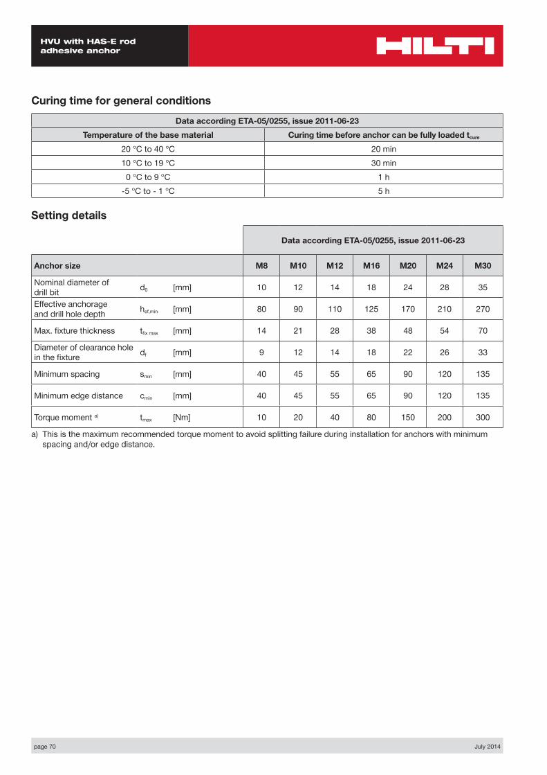
Curing time for general conditions
Data according ETA-05/0255, issue 2011-06-23Temperature of the base material Curing time before anchor can be fully loaded tcure
20 °C to 40 °C 20 min10 °C to 19 °C 30 min
0 °C to 9 °C 1 h-5 °C to - 1 °C 5 h
Setting details
Data according ETA-05/0255, issue 2011-06-23
Anchor size M8 M10 M12 M16 M20 M24 M30
Nominal diameter of drill bit d0 [mm] 10 12 14 18 24 28 35
Effective anchorage and drill hole depth hef,min [mm] 80 90 110 125 170 210 270
Max. fixture thickness tfix max [mm] 14 21 28 38 48 54 70
Diameter of clearance hole in the fixture df [mm] 9 12 14 18 22 26 33
Minimum spacing smin [mm] 40 45 55 65 90 120 135
Minimum edge distance cmin [mm] 40 45 55 65 90 120 135
Torque moment a) tmax [Nm] 10 20 40 80 150 200 300
a) This is the maximum recommended torque moment to avoid splitting failure during installation for anchors with minimum spacing and/or edge distance.
page 72 July 2014
HVU with HIS-(R)N adhesive anchor
CE conformity
Small edge distance
& spacing
European Technical Approval
Concrete
A4 316
Corrosion resistance
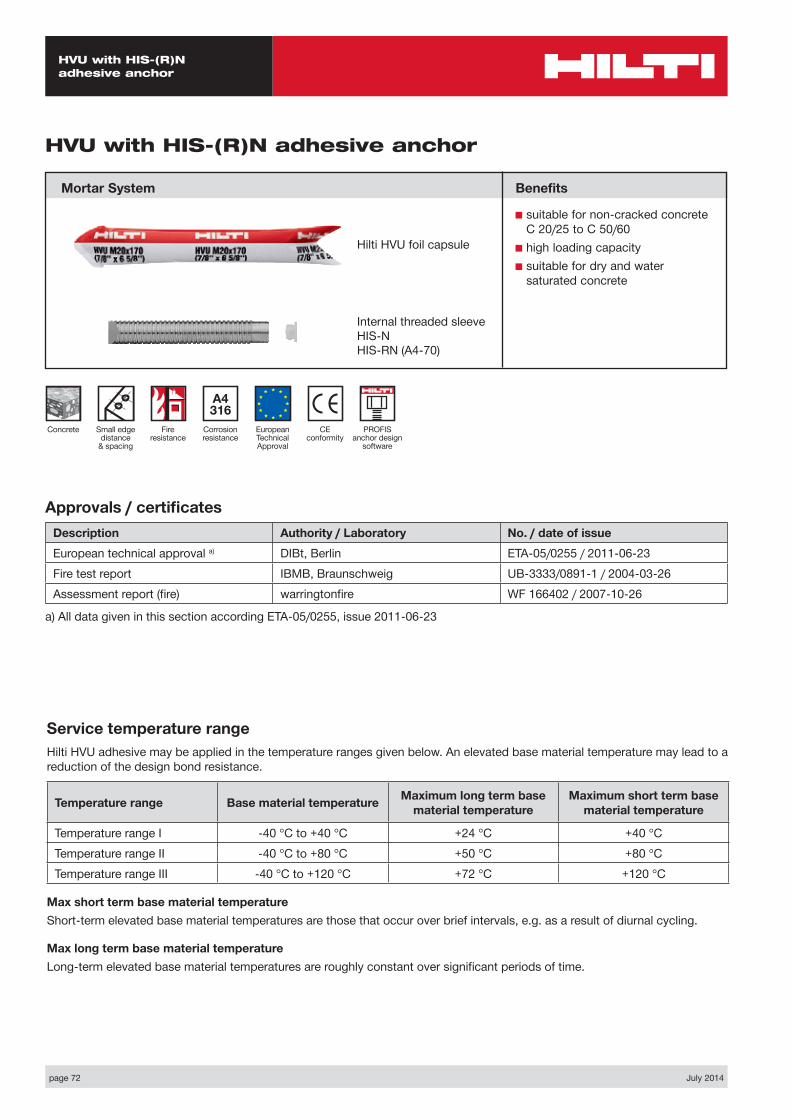
HVU with HIS-(R)N adhesive anchor
Mortar System
Service temperature rangeHilti HVU adhesive may be applied in the temperature ranges given below. An elevated base material temperature may lead to a reduction of the design bond resistance.
Temperature range Base material temperature Maximum long term base material temperature
Maximum short term base material temperature
Temperature range I -40 °C to +40 °C +24 °C +40 °CTemperature range II -40 °C to +80 °C +50 °C +80 °CTemperature range III -40 °C to +120 °C +72 °C +120 °C
Max short term base material temperatureShort-term elevated base material temperatures are those that occur over brief intervals, e.g. as a result of diurnal cycling.
Max long term base material temperatureLong-term elevated base material temperatures are roughly constant over significant periods of time.
Benefits
■ suitable for non-cracked concrete C 20/25 to C 50/60
■ high loading capacity■ suitable for dry and water
saturated concrete
Fire resistance
Hilti HVU foil capsule
Internal threaded sleeve HIS-N HIS-RN (A4-70)
Approvals / certificatesDescription Authority / Laboratory No. / date of issueEuropean technical approval a) DIBt, Berlin ETA-05/0255 / 2011-06-23Fire test report IBMB, Braunschweig UB-3333/0891-1 / 2004-03-26Assessment report (fire) warringtonfire WF 166402 / 2007-10-26
a) All data given in this section according ETA-05/0255, issue 2011-06-23
PROFIS anchor design
software
July 2014 page 73
HVU with HIS-(R)N adhesive anchor
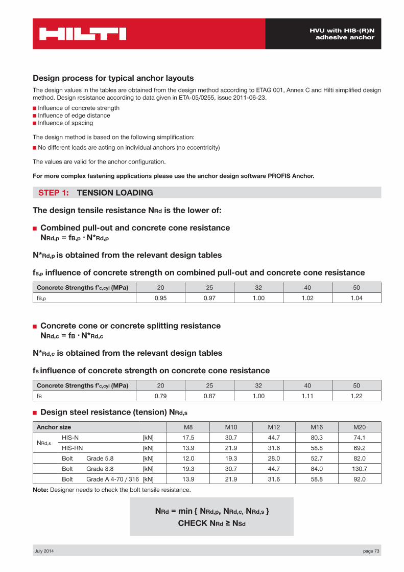
NRd = min { NRd,p, NRd,c, NRd,s } CHECK NRd ≥ NSd
Design process for typical anchor layoutsThe design values in the tables are obtained from the design method according to ETAG 001, Annex C and Hilti simplified design method. Design resistance according to data given in ETA-05/0255, issue 2011-06-23.■ Influence of concrete strength ■ Influence of edge distance ■ Influence of spacing
The design method is based on the following simplification:■ No different loads are acting on individual anchors (no eccentricity)
The values are valid for the anchor configuration.
For more complex fastening applications please use the anchor design software PROFIS Anchor.
STEP 1: TENSION LOADING
The design tensile resistance NRd is the lower of:
■ Combined pull-out and concrete cone resistance NRd,p = fB,p • N*Rd,p
N*Rd,p is obtained from the relevant design tables
fB,p influence of concrete strength on combined pull-out and concrete cone resistance
Concrete Strengths f’c,cyl (MPa) 20 25 32 40 50fB,p 0.95 0.97 1.00 1.02 1.04
■ Concrete cone or concrete splitting resistance NRd,c = fB • N*Rd,c
N*Rd,c is obtained from the relevant design tables
fB influence of concrete strength on concrete cone resistance
Concrete Strengths f’c,cyl (MPa) 20 25 32 40 50fB 0.79 0.87 1.00 1.11 1.22
■ Design steel resistance (tension) NRd,s
Anchor size M8 M10 M12 M16 M20
NRd,sHIS-N [kN] 17.5 30.7 44.7 80.3 74.1HIS-RN [kN] 13.9 21.9 31.6 58.8 69.2Bolt Grade 5.8 [kN] 12.0 19.3 28.0 52.7 82.0Bolt Grade 8.8 [kN] 19.3 30.7 44.7 84.0 130.7Bolt Grade A 4-70 / 316 [kN] 13.9 21.9 31.6 58.8 92.0
Note: Designer needs to check the bolt tensile resistance.
page 74 July 2014
HVU with HIS-(R)N adhesive anchor
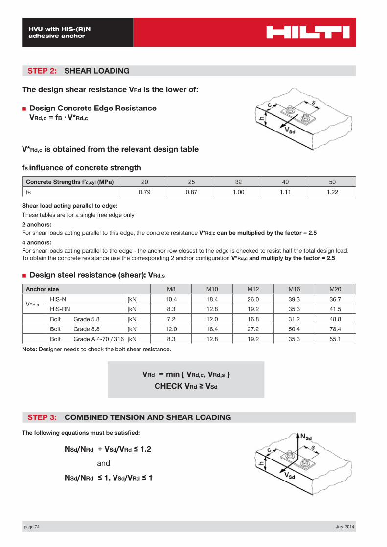
STEP 2: SHEAR LOADING
The design shear resistance VRd is the lower of:
■ Design Concrete Edge Resistance VRd,c = fB • V*Rd,c
V*Rd,c is obtained from the relevant design table
fB influence of concrete strength
Concrete Strengths f’c,cyl (MPa) 20 25 32 40 50fB 0.79 0.87 1.00 1.11 1.22
Shear load acting parallel to edge:These tables are for a single free edge only2 anchors:For shear loads acting parallel to this edge, the concrete resistance V*Rd,c can be multiplied by the factor = 2.54 anchors:For shear loads acting parallel to the edge - the anchor row closest to the edge is checked to resist half the total design load. To obtain the concrete resistance use the corresponding 2 anchor configuration V*Rd,c and multiply by the factor = 2.5
■ Design steel resistance (shear): VRd,s
Anchor size M8 M10 M12 M16 M20
VRd,sHIS-N [kN] 10.4 18.4 26.0 39.3 36.7HIS-RN [kN] 8.3 12.8 19.2 35.3 41.5Bolt Grade 5.8 [kN] 7.2 12.0 16.8 31.2 48.8Bolt Grade 8.8 [kN] 12.0 18.4 27.2 50.4 78.4Bolt Grade A 4-70 / 316 [kN] 8.3 12.8 19.2 35.3 55.1
Note: Designer needs to check the bolt shear resistance.
STEP 3: COMBINED TENSION AND SHEAR LOADING
The following equations must be satisfied:
NSd/NRd + VSd/VRd ≤ 1.2
and
NSd/NRd ≤ 1, VSd/VRd ≤ 1
VRd = min { VRd,c, VRd,s } CHECK VRd ≥ VSd
July 2014 page 75
HVU with HIS-(R)N adhesive anchor
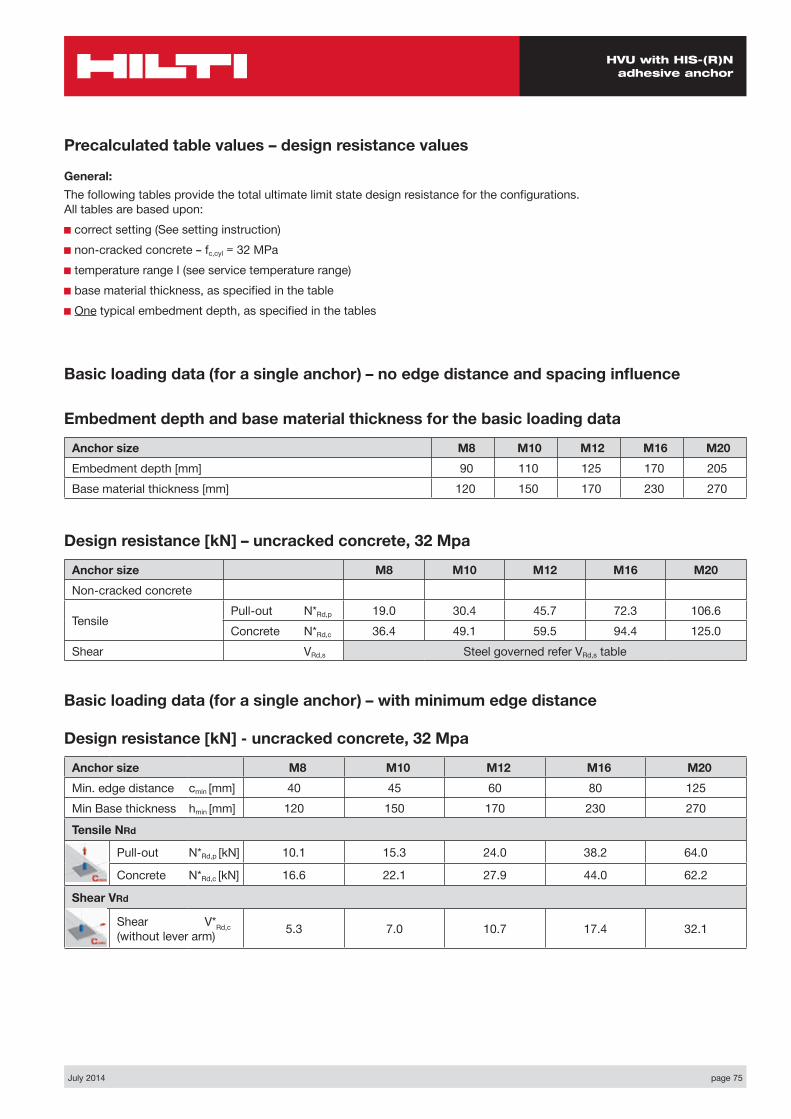
Basic loading data (for a single anchor) – no edge distance and spacing influence
Embedment depth and base material thickness for the basic loading data
Anchor size M8 M10 M12 M16 M20Embedment depth [mm] 90 110 125 170 205Base material thickness [mm] 120 150 170 230 270
Precalculated table values – design resistance values
General:The following tables provide the total ultimate limit state design resistance for the configurations. All tables are based upon:■ correct setting (See setting instruction)■ non-cracked concrete – fc,cyl = 32 MPa■ temperature range I (see service temperature range)■ base material thickness, as specified in the table■ One typical embedment depth, as specified in the tables
Design resistance [kN] – uncracked concrete, 32 Mpa
Anchor size M8 M10 M12 M16 M20Non-cracked concrete
Tensile Pull-out N*Rd,p 19.0 30.4 45.7 72.3 106.6Concrete N*Rd,c 36.4 49.1 59.5 94.4 125.0
Shear VRd,s Steel governed refer VRd,s table
Basic loading data (for a single anchor) – with minimum edge distance
Design resistance [kN] - uncracked concrete, 32 Mpa
Anchor size M8 M10 M12 M16 M20Min. edge distance cmin [mm] 40 45 60 80 125Min Base thickness hmin [mm] 120 150 170 230 270
Tensile NRd
Pull-out N*Rd,p [kN] 10.1 15.3 24.0 38.2 64.0
Concrete N*Rd,c [kN] 16.6 22.1 27.9 44.0 62.2
Shear VRd
Shear V*Rd,c (without lever arm) 5.3 7.0 10.7 17.4 32.1
page 76 July 2014
HVU with HIS-(R)N adhesive anchor
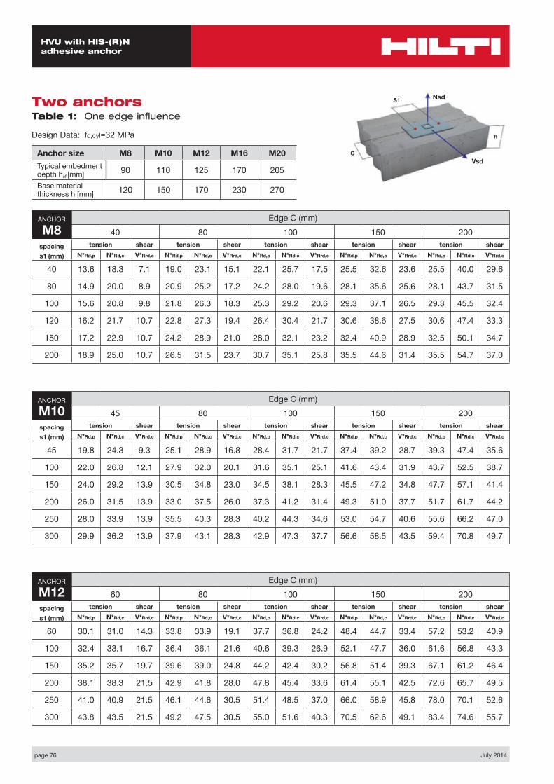
Nsd
Vsd
S1
C
h
Two anchors Table 1: One edge influence
Design Data: fc,cyl=32 MPa
Anchor size M8 M10 M12 M16 M20Typical embedment depth hef [mm] 90 110 125 170 205
Base material thickness h [mm] 120 150 170 230 270
ANCHOR
M8Edge C (mm)
40 80 100 150 200spacings1 (mm)
tension shear tension shear tension shear tension shear tension shearN*Rd,p N*Rd,c V*Rrd,c N*Rd,p N*Rd,c V*Rrd,c N*Rd,p N*Rd,c V*Rrd,c N*Rd,p N*Rd,c V*Rrd,c N*Rd,p N*Rd,c V*Rrd,c
40 13.6 18.3 7.1 19.0 23.1 15.1 22.1 25.7 17.5 25.5 32.6 23.6 25.5 40.0 29.6
80 14.9 20.0 8.9 20.9 25.2 17.2 24.2 28.0 19.6 28.1 35.6 25.6 28.1 43.7 31.5
100 15.6 20.8 9.8 21.8 26.3 18.3 25.3 29.2 20.6 29.3 37.1 26.5 29.3 45.5 32.4
120 16.2 21.7 10.7 22.8 27.3 19.4 26.4 30.4 21.7 30.6 38.6 27.5 30.6 47.4 33.3
150 17.2 22.9 10.7 24.2 28.9 21.0 28.0 32.1 23.2 32.4 40.9 28.9 32.5 50.1 34.7
200 18.9 25.0 10.7 26.5 31.5 23.7 30.7 35.1 25.8 35.5 44.6 31.4 35.5 54.7 37.0
ANCHOR
M10Edge C (mm)
45 80 100 150 200spacings1 (mm)
tension shear tension shear tension shear tension shear tension shearN*Rd,p N*Rd,c V*Rrd,c N*Rd,p N*Rd,c V*Rrd,c N*Rd,p N*Rd,c V*Rrd,c N*Rd,p N*Rd,c V*Rrd,c N*Rd,p N*Rd,c V*Rrd,c
45 19.8 24.3 9.3 25.1 28.9 16.8 28.4 31.7 21.7 37.4 39.2 28.7 39.3 47.4 35.6
100 22.0 26.8 12.1 27.9 32.0 20.1 31.6 35.1 25.1 41.6 43.4 31.9 43.7 52.5 38.7
150 24.0 29.2 13.9 30.5 34.8 23.0 34.5 38.1 28.3 45.5 47.2 34.8 47.7 57.1 41.4
200 26.0 31.5 13.9 33.0 37.5 26.0 37.3 41.2 31.4 49.3 51.0 37.7 51.7 61.7 44.2
250 28.0 33.9 13.9 35.5 40.3 28.3 40.2 44.3 34.6 53.0 54.7 40.6 55.6 66.2 47.0
300 29.9 36.2 13.9 37.9 43.1 28.3 42.9 47.3 37.7 56.6 58.5 43.5 59.4 70.8 49.7
ANCHOR
M12Edge C (mm)
60 80 100 150 200spacings1 (mm)
tension shear tension shear tension shear tension shear tension shearN*Rd,p N*Rd,c V*Rrd,c N*Rd,p N*Rd,c V*Rrd,c N*Rd,p N*Rd,c V*Rrd,c N*Rd,p N*Rd,c V*Rrd,c N*Rd,p N*Rd,c V*Rrd,c
60 30.1 31.0 14.3 33.8 33.9 19.1 37.7 36.8 24.2 48.4 44.7 33.4 57.2 53.2 40.9
100 32.4 33.1 16.7 36.4 36.1 21.6 40.6 39.3 26.9 52.1 47.7 36.0 61.6 56.8 43.3
150 35.2 35.7 19.7 39.6 39.0 24.8 44.2 42.4 30.2 56.8 51.4 39.3 67.1 61.2 46.4
200 38.1 38.3 21.5 42.9 41.8 28.0 47.8 45.4 33.6 61.4 55.1 42.5 72.6 65.7 49.5
250 41.0 40.9 21.5 46.1 44.6 30.5 51.4 48.5 37.0 66.0 58.9 45.8 78.0 70.1 52.6
300 43.8 43.5 21.5 49.2 47.5 30.5 55.0 51.6 40.3 70.5 62.6 49.1 83.4 74.6 55.7

July 2014 page 77
HVU with HIS-(R)N adhesive anchor
ANCHOR
M16Edge C (mm)
80 100 150 200 250spacings1 (mm)
tension shear tension shear tension shear tension shear tension shearN*Rd,p N*Rd,c V*Rrd,c N*Rd,p N*Rd,c V*Rrd,c N*Rd,p N*Rd,c V*Rrd,c N*Rd,p N*Rd,c V*Rrd,c N*Rd,p N*Rd,c V*Rrd,c
80 48.0 48.7 23.3 52.6 52.0 28.9 64.6 60.6 44.3 77.9 69.7 53.8 90.8 79.4 62.7
100 49.4 49.9 24.7 54.1 53.3 30.4 66.5 62.0 46.0 80.1 71.4 55.3 93.5 81.4 64.2
150 52.9 52.9 28.4 57.9 56.5 34.2 71.2 65.8 50.1 85.8 75.7 59.3 100.1 86.2 67.9
200 56.4 55.9 32.0 61.8 59.7 38.0 75.9 69.5 54.3 91.5 80.0 63.3 106.7 91.1 71.7
250 59.9 58.9 34.9 65.6 62.9 41.8 80.7 73.2 58.5 97.1 84.2 67.2 113.3 96.0 75.5
300 63.4 61.9 34.9 69.4 66.0 45.6 85.3 76.9 62.7 102.8 88.5 71.2 119.9 108.0 79.3
ANCHOR
M20Edge C (mm)
125 150 200 250 300spacings1 (mm)
tension shear tension shear tension shear tension shear tension shearN*Rd,p N*Rd,c V*Rrd,c N*Rd,p N*Rd,c V*Rrd,c N*Rd,p N*Rd,c V*Rrd,c N*Rd,p N*Rd,c V*Rrd,c N*Rd,p N*Rd,c V*Rrd,c
125 81.7 70.8 42.7 89.4 75.3 51.2 105.9 84.9 65.7 123.7 95.0 75.3 136.0 105.6 84.9
150 84.3 72.5 44.9 92.3 77.2 53.4 109.3 86.9 68.0 127.7 97.3 77.5 140.4 108.1 87.0
200 89.6 75.9 49.2 98.1 80.8 57.8 116.2 91.0 72.5 135.7 101.8 81.8 149.3 113.2 91.1
250 94.9 79.3 53.4 103.9 84.4 62.3 123.1 95.1 77.0 143.7 106.4 86.1 158.1 118.3 95.3
300 100.2 82.7 57.7 109.7 88.0 66.7 129.9 99.2 81.5 151.7 111.0 90.4 166.9 123.3 99.4
350 105.4 86.1 62.0 115.5 91.7 71.2 136.8 103.3 86.1 159.7 115.5 94.7 175.7 128.4 103.5

page 78 July 2014
HVU with HIS-(R)N adhesive anchor
Four anchors Table 2: One edge influence
Design Data: fc,cyl=32 MPa
Anchor size M8 M10 M12 M16 M20Typical embedment depth hef [mm] 90 110 125 170 205
Base material thickness h [mm] 120 150 170 230 270
Nsd
Vsd
S2
S1
C
h
ANCHOR
M8Edge C (mm)
40 80 100 150 200spacing
s1= s2 (mm)
tension shear tension shear tension shear tension shear tension shearN*Rd,p N*Rd,c V*Rrd,c N*Rd,p N*Rd,c V*Rrd,c N*Rd,p N*Rd,c V*Rrd,c N*Rd,p N*Rd,c V*Rrd,c N*Rd,p N*Rd,c V*Rrd,c
40 20.1 21.4 14.2 27.1 26.4 20.0 30.9 29.1 22.4 35.3 36.4 28.4 35.3 44.1 34.3
80 25.4 26.7 17.8 33.3 32.4 26.8 37.6 35.5 29.1 42.5 43.8 35.0 42.5 52.5 40.8
100 28.2 29.6 19.6 36.6 35.7 30.1 41.2 39.0 32.4 46.3 47.8 38.2 46.3 57.0 44.0
120 31.2 32.6 21.4 40.0 39.1 33.3 44.8 42.6 35.6 50.3 51.9 41.4 50.3 61.7 47.1
150 35.7 37.4 21.4 45.3 44.5 38.2 50.5 48.3 40.5 56.4 58.5 46.2 56.4 69.1 51.8
200 43.6 46.0 21.4 54.5 54.2 46.1 60.3 58.6 48.4 66.9 70.2 54.0 66.9 82.4 59.6
ANCHOR
M10Edge C (mm)
45 80 100 150 200spacing
s1= s2 (mm)
tension shear tension shear tension shear tension shear tension shearN*Rd,p N*Rd,c V*Rrd,c N*Rd,p N*Rd,c V*Rrd,c N*Rd,p N*Rd,c V*Rrd,c N*Rd,p N*Rd,c V*Rrd,c N*Rd,p N*Rd,c V*Rrd,c
45 28.1 28.1 18.5 34.7 33.0 25.2 38.8 35.9 28.0 49.9 43.8 34.9 52.2 52.3 41.8
100 36.6 36.4 24.2 44.3 42.1 36.0 49.0 45.5 38.7 61.7 54.6 45.4 64.3 64.5 52.0
150 45.3 44.8 27.8 53.9 51.2 45.4 59.2 55.1 48.0 73.4 65.5 54.6 76.3 76.7 61.1
200 54.5 54.0 27.8 64.2 61.3 52.0 70.0 65.7 57.2 85.9 77.3 63.7 89.1 89.9 70.1
250 64.2 64.0 27.8 75.0 72.2 56.7 81.5 77.2 66.2 98.9 90.2 72.6 102.5 104.2 79.0
300 74.4 74.9 27.8 86.2 84.1 56.8 93.4 89.6 75.1 112.5 104.0 81.5 116.4 119.6 87.8
ANCHOR
M12Edge C (mm)
60 80 100 150 200spacing
s1= s2 (mm)
tension shear tension shear tension shear tension shear tension shearN*Rd,p N*Rd,c V*Rrd,c N*Rd,p N*Rd,c V*Rrd,c N*Rd,p N*Rd,c V*Rrd,c N*Rd,p N*Rd,c V*Rrd,c N*Rd,p N*Rd,c V*Rrd,c
60 41.3 36.7 28.6 45.7 39.7 31.9 50.4 42.8 34.9 63.0 51.1 42.4 73.4 60.0 49.7
100 49.3 43.2 33.4 54.3 46.5 40.4 59.4 49.9 43.4 73.4 59.0 50.6 84.7 68.9 57.9
150 60.3 52.0 40.0 65.9 55.7 49.6 71.8 59.6 53.6 87.4 69.8 60.8 100.1 80.8 67.9
200 72.3 61.6 42.9 78.6 65.7 56.0 85.1 70.1 63.7 102.6 81.5 70.7 116.7 93.7 77.7
250 85.1 71.9 43.0 92.1 76.6 61.0 99.4 81.4 73.5 118.7 94.0 80.5 134.4 107.5 87.4
300 98.8 83.1 43.0 106.5 88.3 61.0 114.5 93.5 80.6 135.8 107.4 90.1 153.0 122.3 97.0
July 2014 page 79
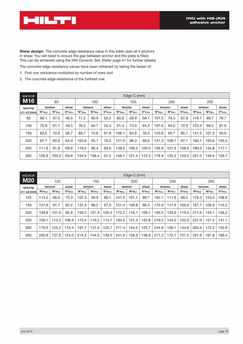
HVU with HIS-(R)N adhesive anchor
Shear design: The concrete edge resistance value in this table uses all 4 anchors in shear. You will need to ensure the gap between anchor and the plate is filled. This can be achieved using the Hilti Dynamic Set. (Refer page 41 for further details)The concrete edge resistance values have been obtained by taking the lesser of:1. First row resistance multiplied by number of rows and 2. The concrete edge resistance of the furthest row.
ANCHOR
M16Edge C (mm)
80 100 150 200 250spacing
s1= s2 (mm)
tension shear tension shear tension shear tension shear tension shearN*Rd,p N*Rd,c V*Rrd,c N*Rd,p N*Rd,c V*Rrd,c N*Rd,p N*Rd,c V*Rrd,c N*Rd,p N*Rd,c V*Rrd,c N*Rd,p N*Rd,c V*Rrd,c
80 66.1 57.5 46.5 71.5 60.9 50.2 85.9 69.9 59.1 101.5 79.5 67.9 116.7 89.7 76.7
100 70.9 61.1 49.5 76.5 64.7 55.3 91.4 74.0 64.2 107.6 84.0 72.9 123.4 94.5 81.6
150 83.5 70.6 56.7 89.7 74.6 67.9 106.1 84.8 76.5 123.9 95.7 85.1 141.2 107.2 93.6
200 97.1 80.9 64.0 103.9 85.1 76.0 121.9 96.3 88.6 141.2 108.1 97.1 160.1 120.6 105.5
250 111.6 91.8 69.8 119.0 96.4 83.6 138.6 108.5 100.5 159.6 121.3 108.9 180.0 134.8 117.1
300 126.8 103.3 69.8 134.9 108.4 91.2 156.1 121.4 112.3 178.9 135.2 120.5 201.0 149.8 128.7
ANCHOR
M20Edge C (mm)
125 150 200 250 300spacing
s1= s2 (mm)
tension shear tension shear tension shear tension shear tension shearN*Rd,p N*Rd,c V*Rrd,c N*Rd,p N*Rd,c V*Rrd,c N*Rd,p N*Rd,c V*Rrd,c N*Rd,p N*Rd,c V*Rrd,c N*Rd,p N*Rd,c V*Rrd,c
125 113.2 86.0 75.3 122.3 90.9 80.1 141.5 101.1 89.7 162.1 111.8 99.2 176.3 123.0 108.6
150 121.8 91.1 82.2 131.3 96.2 87.0 151.4 106.8 96.4 172.9 117.9 105.8 187.7 129.5 115.2
200 139.9 101.9 95.8 150.3 107.4 100.4 172.2 118.7 109.7 195.5 130.6 119.0 211.6 143.1 128.2
250 159.1 113.3 106.9 170.4 119.2 113.7 194.2 131.3 122.8 219.5 144.0 132.0 237.0 157.3 141.1
300 179.5 125.3 115.4 191.7 131.5 126.7 217.4 144.5 135.7 244.8 158.1 144.8 263.6 172.2 153.8
350 200.9 137.8 124.0 214.2 144.5 139.5 241.9 158.3 148.5 271.3 172.7 157.5 291.6 187.8 166.4
page 80 July 2014
HVU with HIS-(R)N adhesive anchor
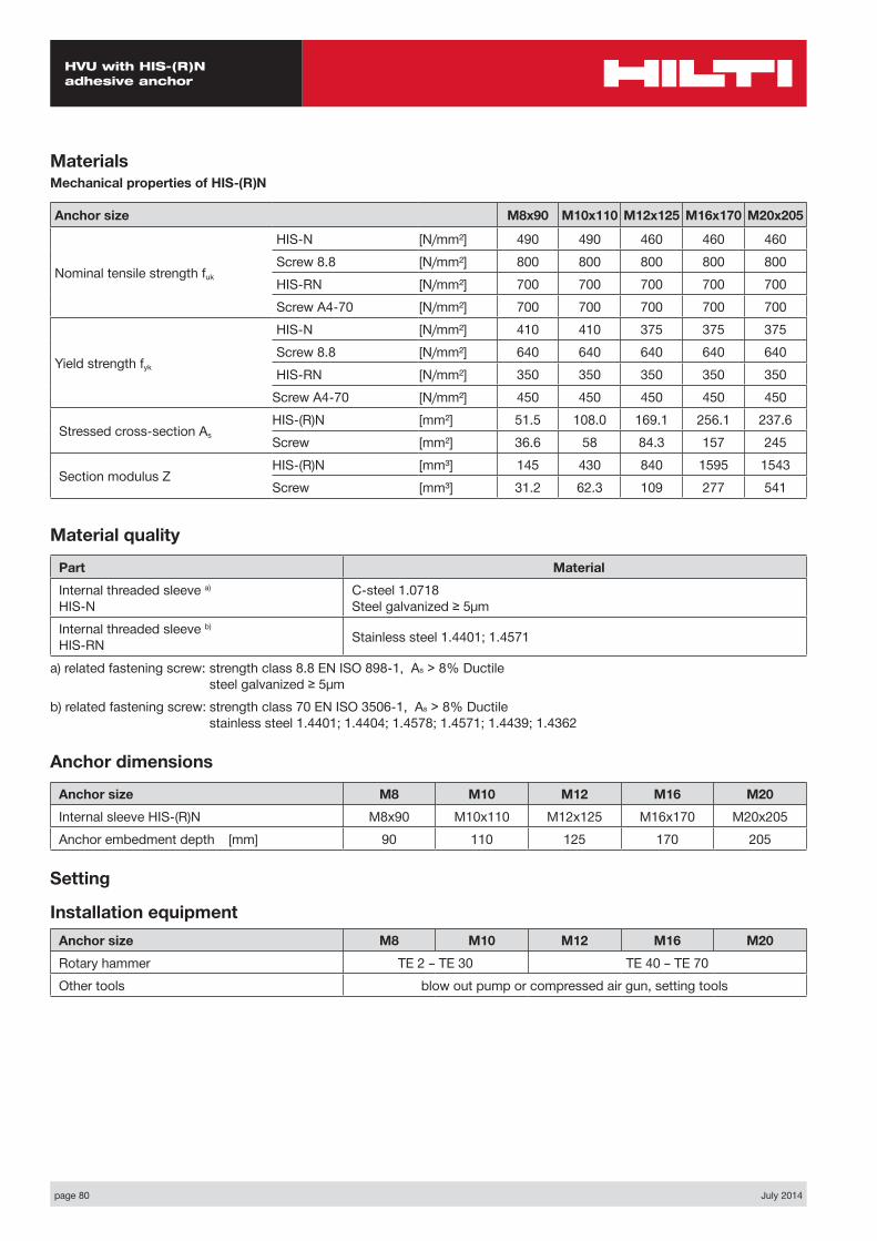
MaterialsMechanical properties of HIS-(R)N
Anchor size M8x90 M10x110 M12x125 M16x170 M20x205
Nominal tensile strength fuk
HIS-N [N/mm²] 490 490 460 460 460Screw 8.8 [N/mm²] 800 800 800 800 800HIS-RN [N/mm²] 700 700 700 700 700Screw A4-70 [N/mm²] 700 700 700 700 700
Yield strength fyk
HIS-N [N/mm²] 410 410 375 375 375Screw 8.8 [N/mm²] 640 640 640 640 640HIS-RN [N/mm²] 350 350 350 350 350
Screw A4-70 [N/mm²] 450 450 450 450 450
Stressed cross-section AsHIS-(R)N [mm²] 51.5 108.0 169.1 256.1 237.6Screw [mm²] 36.6 58 84.3 157 245
Section modulus ZHIS-(R)N [mm³] 145 430 840 1595 1543Screw [mm³] 31.2 62.3 109 277 541
Material quality
Part MaterialInternal threaded sleeve a) HIS-N
C-steel 1.0718 Steel galvanized ≥ 5μm
Internal threaded sleeve b) HIS-RN Stainless steel 1.4401; 1.4571
a) related fastening screw: strength class 8.8 EN ISO 898-1, As > 8% Ductile steel galvanized ≥ 5μm
b) related fastening screw: strength class 70 EN ISO 3506-1, As > 8% Ductile stainless steel 1.4401; 1.4404; 1.4578; 1.4571; 1.4439; 1.4362
Anchor dimensions
Anchor size M8 M10 M12 M16 M20Internal sleeve HIS-(R)N M8x90 M10x110 M12x125 M16x170 M20x205Anchor embedment depth [mm] 90 110 125 170 205
Setting
Installation equipmentAnchor size M8 M10 M12 M16 M20Rotary hammer TE 2 – TE 30 TE 40 – TE 70Other tools blow out pump or compressed air gun, setting tools
July 2014 page 81
HVU with HIS-(R)N adhesive anchor
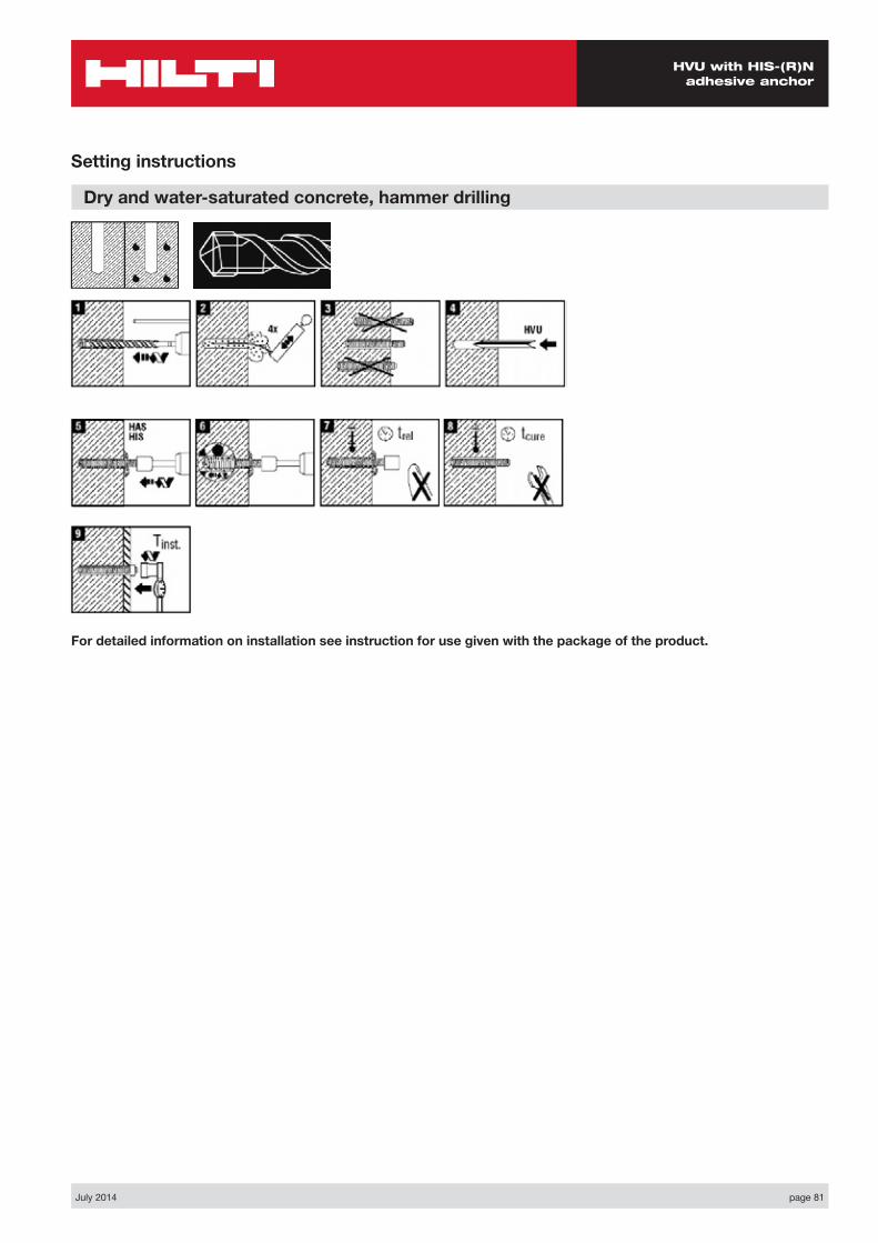
Setting instructions
Dry and water-saturated concrete, hammer drilling
For detailed information on installation see instruction for use given with the package of the product.
page 82 July 2014
HVU with HIS-(R)N adhesive anchor
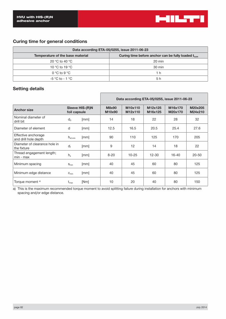
Curing time for general conditions
Data according ETA-05/0255, issue 2011-06-23Temperature of the base material Curing time before anchor can be fully loaded tcure
20 °C to 40 °C 20 min10 °C to 19 °C 30 min
0 °C to 9 °C 1 h-5 °C to - 1 °C 5 h
Setting details
Data according ETA-05/0255, issue 2011-06-23
Anchor size Sleeve HIS-(R)N foil capsule
M8x90 M10x90
M10x110 M12x110
M12x125 M16x125
M16x170 M20x170
M20x205 M24x210
Nominal diameter of drill bit d0 [mm] 14 18 22 28 32
Diameter of element d [mm] 12.5 16.5 20.5 25.4 27.6
Effective anchorage and drill hole depth hef,min [mm] 90 110 125 170 205
Diameter of clearance hole in the fixture df [mm] 9 12 14 18 22
Thread engagement length; min - max hs [mm] 8-20 10-25 12-30 16-40 20-50
Minimum spacing smin [mm] 40 45 60 80 125
Minimum edge distance cmin [mm] 40 45 60 80 125
Torque moment a) tmax [Nm] 10 20 40 80 150
a) This is the maximum recommended torque moment to avoid splitting failure during installation for anchors with minimum spacing and/or edge distance.
page 84 July 2014
Hilti HIT-HY 200 with HIT-V
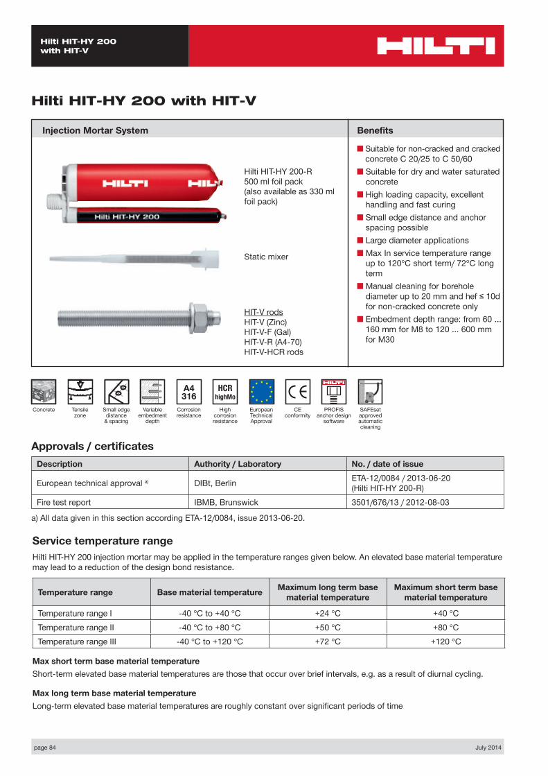
Hilti HIT-HY 200 with HIT-V
Injection Mortar System Benefits
■ Suitable for non-cracked and cracked concrete C 20/25 to C 50/60
■ Suitable for dry and water saturated concrete
■ High loading capacity, excellent handling and fast curing
■ Small edge distance and anchor spacing possible
■ Large diameter applications■ Max In service temperature range
up to 120°C short term/ 72°C long term
■ Manual cleaning for borehole diameter up to 20 mm and hef ≤ 10d for non-cracked concrete only
■ Embedment depth range: from 60 ... 160 mm for M8 to 120 ... 600 mm for M30
Approvals / certificatesDescription Authority / Laboratory No. / date of issue
European technical approval a) DIBt, Berlin ETA-12/0084 / 2013-06-20 (Hilti HIT-HY 200-R)
Fire test report IBMB, Brunswick 3501/676/13 / 2012-08-03
a) All data given in this section according ETA-12/0084, issue 2013-06-20.
Service temperature rangeHilti HIT-HY 200 injection mortar may be applied in the temperature ranges given below. An elevated base material temperature may lead to a reduction of the design bond resistance.
Temperature range Base material temperature Maximum long term base material temperature
Maximum short term base material temperature
Temperature range I -40 °C to +40 °C +24 °C +40 °CTemperature range II -40 °C to +80 °C +50 °C +80 °CTemperature range III -40 °C to +120 °C +72 °C +120 °C
Max short term base material temperatureShort-term elevated base material temperatures are those that occur over brief intervals, e.g. as a result of diurnal cycling.
Max long term base material temperatureLong-term elevated base material temperatures are roughly constant over significant periods of time
Hilti HIT-HY 200-R500 ml foil pack(also available as 330 ml foil pack)
Static mixer
HIT-V rodsHIT-V (Zinc)HIT-V-F (Gal)HIT-V-R (A4-70)HIT-V-HCR rods
CE conformity
Small edge distance
& spacing
European Technical Approval
Concrete
A4 316
Corrosion resistance
HCR highMo
High corrosion resistance
Variable embedment
depth
Tensile zone
PROFIS anchor design
software
SAFEset approved automatic cleaning
July 2014 page 85
Hilti HIT-HY 200 with HIT-V
Design process for typical anchor layoutsThe design values in the tables are obtained from Profis V2.2.1 in compliance with the design method according to EOTA TR 029. Design resistance according to data given in ETA-12/0084, issue 2013-06-20.■ Influence of concrete strength ■ Influence of edge distance ■ Influence of spacing
The design method is based on the following simplification:■ No different loads are acting on individual anchors (no eccentricity)
The values are valid for the anchor configuration.
For more complex fastening applications please use the anchor design software PROFIS Anchor.
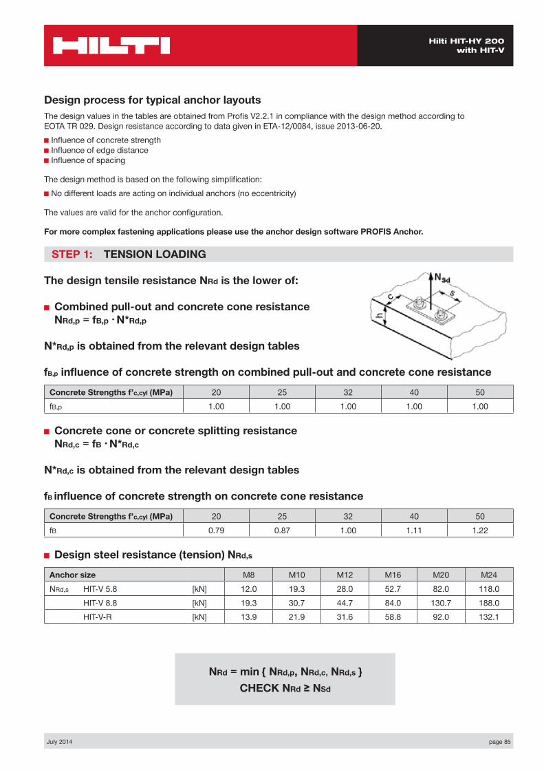
STEP 1: TENSION LOADING
The design tensile resistance NRd is the lower of:
■ Combined pull-out and concrete cone resistance NRd,p = fB,p • N*Rd,p
N*Rd,p is obtained from the relevant design tables
fB,p influence of concrete strength on combined pull-out and concrete cone resistance
Concrete Strengths f’c,cyl (MPa) 20 25 32 40 50fB,p 1.00 1.00 1.00 1.00 1.00
■ Concrete cone or concrete splitting resistance NRd,c = fB • N*Rd,c
N*Rd,c is obtained from the relevant design tables
fB influence of concrete strength on concrete cone resistance
Concrete Strengths f’c,cyl (MPa) 20 25 32 40 50fB 0.79 0.87 1.00 1.11 1.22
■ Design steel resistance (tension) NRd,s
Anchor size M8 M10 M12 M16 M20 M24NRd,s HIT-V 5.8 [kN] 12.0 19.3 28.0 52.7 82.0 118.0
HIT-V 8.8 [kN] 19.3 30.7 44.7 84.0 130.7 188.0HIT-V-R [kN] 13.9 21.9 31.6 58.8 92.0 132.1
NRd = min { NRd,p, NRd,c, NRd,s } CHECK NRd ≥ NSd
page 86 July 2014
Hilti HIT-HY 200 with HIT-V
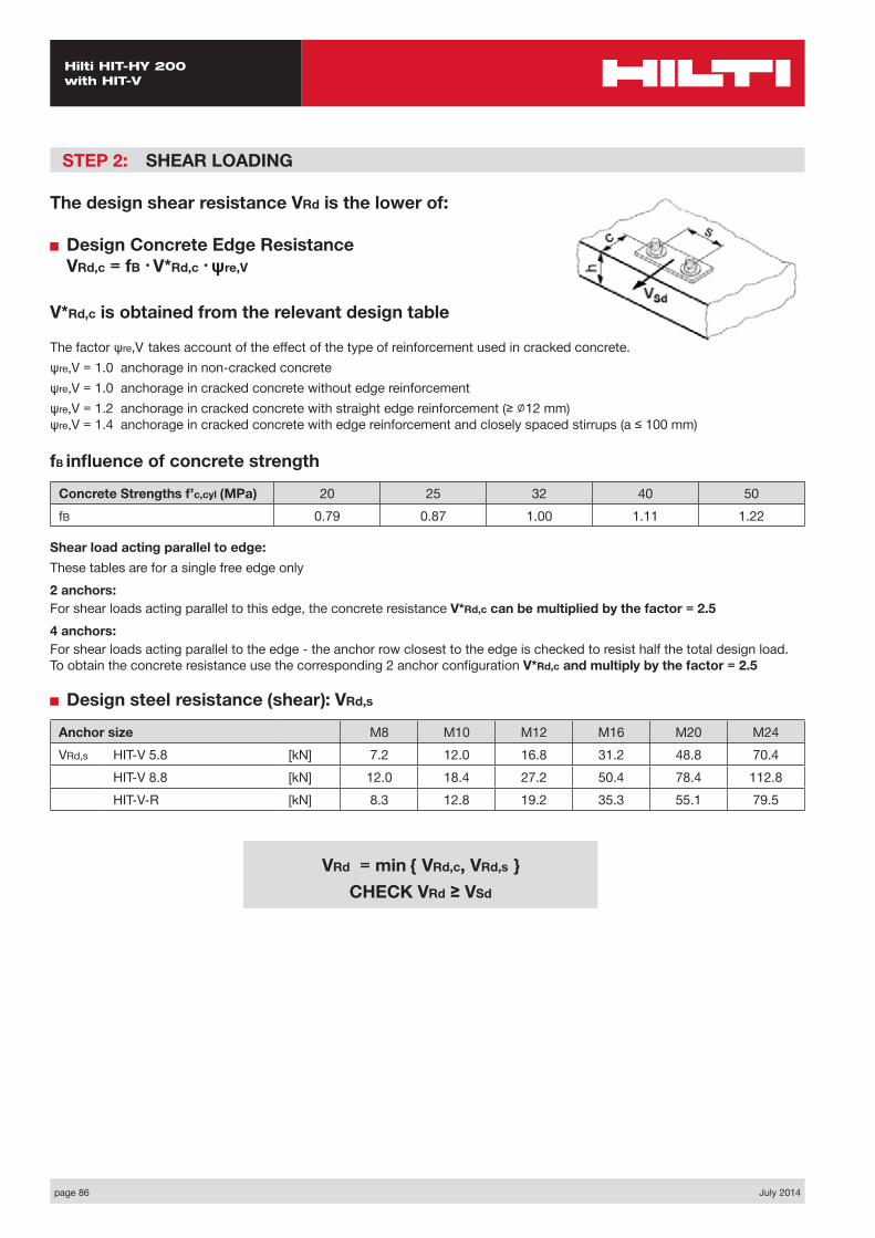
STEP 2: SHEAR LOADING
The design shear resistance VRd is the lower of:
■ Design Concrete Edge Resistance VRd,c = fB • V*Rd,c • ψre,V
V*Rd,c is obtained from the relevant design table
The factor ψre,V takes account of the effect of the type of reinforcement used in cracked concrete.ψre,V = 1.0 anchorage in non-cracked concreteψre,V = 1.0 anchorage in cracked concrete without edge reinforcementψre,V = 1.2 anchorage in cracked concrete with straight edge reinforcement (≥ ∅12 mm) ψre,V = 1.4 anchorage in cracked concrete with edge reinforcement and closely spaced stirrups (a ≤ 100 mm)
fB influence of concrete strength
Concrete Strengths f’c,cyl (MPa) 20 25 32 40 50fB 0.79 0.87 1.00 1.11 1.22
Shear load acting parallel to edge:These tables are for a single free edge only2 anchors:For shear loads acting parallel to this edge, the concrete resistance V*Rd,c can be multiplied by the factor = 2.54 anchors:For shear loads acting parallel to the edge - the anchor row closest to the edge is checked to resist half the total design load. To obtain the concrete resistance use the corresponding 2 anchor configuration V*Rd,c and multiply by the factor = 2.5
■ Design steel resistance (shear): VRd,s
Anchor size M8 M10 M12 M16 M20 M24VRd,s HIT-V 5.8 [kN] 7.2 12.0 16.8 31.2 48.8 70.4
HIT-V 8.8 [kN] 12.0 18.4 27.2 50.4 78.4 112.8HIT-V-R [kN] 8.3 12.8 19.2 35.3 55.1 79.5
VRd = min { VRd,c, VRd,s } CHECK VRd ≥ VSd

July 2014 page 87
Hilti HIT-HY 200 with HIT-V
STEP 3: COMBINED TENSION AND SHEAR LOADING
The following equations must be satisfied:
NSd/NRd + VSd/VRd ≤ 1.2
and
NSd/NRd ≤ 1, VSd/VRd ≤ 1
page 88 July 2014
Hilti HIT-HY 200 with HIT-V
Basic loading data (for a single anchor) – no edge distance and spacing influence
Embedment depth and base material thickness for the basic loading data
Anchor size M8 M10 M12 M16 M20 M24
Typical embedment depth hef [mm] 80 90 110 125 170 210
Base material thickness h [mm] 110 120 150 200 250 300
Precalculated table values – design resistance values
General:The following tables provide the total ultimate limit state design resistance for the configurations. All tables are based upon:■ correct setting (See setting instruction)■ non cracked and cracked concrete – fc,cyl = 32 MPa■ temperature range I (see service temperature range)■ base material thickness, as specified in the table■ One typical embedment depth, as specified in the tables
The following tables give design values for typical embedment depths. The latest version of the Hilti software Profis allows the engineer to optimise their design by varying the embedment depth according to the applied loads to achieve an economical solution every time. This is done by selecting HIT-V-Rods.For more information on the HIT-V rods please refer to the Chemical Anchor Components & Accessories section on page 266.The anchor design software program Profis can be download from the Hilti Australia website, www.hilti.com.au.
Design resistance: concrete 32 MPa
Anchor size M8 M10 M12 M16 M20 M24Non-cracked concrete
Tensile Concrete Pull N*Rd,p Steel governed refer NRd,s table 69.8 118.7 175.9Concrete Cone N*Rd,c Steel governed refer NRd,s table 49.6 78.7 108.0
Shear VRd,s Steel governed refer VRd,s tableCracked concrete
Tensile Concrete Pull N*Rd,p 6.7 9.4 18.4 27.9 47.5 70.4Concrete Cone N*Rd,c 18.1 21.6 29.2 35.4 56.1 77.0
Shear VRd,s NA Steel governed refer VRd,s table
July 2014 page 89
Hilti HIT-HY 200 with HIT-V
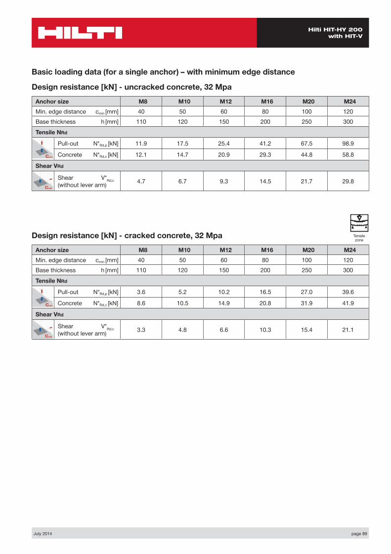
Basic loading data (for a single anchor) – with minimum edge distance
Design resistance [kN] - uncracked concrete, 32 Mpa
Anchor size M8 M10 M12 M16 M20 M24Min. edge distance cmin [mm] 40 50 60 80 100 120Base thickness h [mm] 110 120 150 200 250 300
Tensile NRd
Pull-out N*Rd,p [kN] 11.9 17.5 25.4 41.2 67.5 98.9
Concrete N*Rd,c [kN] 12.1 14.7 20.9 29.3 44.8 58.8
Shear VRd
Shear V*Rd,c (without lever arm) 4.7 6.7 9.3 14.5 21.7 29.8
Design resistance [kN] - cracked concrete, 32 Mpa
Anchor size M8 M10 M12 M16 M20 M24Min. edge distance cmin [mm] 40 50 60 80 100 120Base thickness h [mm] 110 120 150 200 250 300
Tensile NRd
Pull-out N*Rd,p [kN] 3.6 5.2 10.2 16.5 27.0 39.6
Concrete N*Rd,c [kN] 8.6 10.5 14.9 20.8 31.9 41.9
Shear VRd
Shear V*Rd,c (without lever arm) 3.3 4.8 6.6 10.3 15.4 21.1
Tensile zone

page 90 July 2014
Hilti HIT-HY 200 with HIT-V
Nsd
Vsd
S1
C
h
Two anchors Table 1: One edge influence – non cracked concrete
Design Data: fc,cyl=32 MPa
Anchor size M8 M10 M12 M16 M20 M24Typical embedment depth hef [mm] 80 90 110 125 170 210
Base material thickness h [mm] 110 120 150 200 250 300
ANCHOR
M8Edge C (mm)
40 80 100 150 170spacings1 (mm)
tension shear tension shear tension shear tension shear tension shearN*Rd,p N*Rd,c V*Rrd,c N*Rd,p N*Rd,c V*Rrd,c N*Rd,p N*Rd,c V*Rrd,c N*Rd,p N*Rd,c V*Rrd,c N*Rd,p N*Rd,c V*Rrd,c
40 14.5 13.5 6.3 20.4 17.6 13.2 13.6 19.8 15.4 27.1 25.8 21.0 27.1 28.4 23.2
80 16.4 14.9 7.9 23.0 19.4 15.0 26.7 21.8 17.2 30.7 28.5 22.7 30.7 31.4 24.9
100 17.3 15.6 8.6 24.3 20.3 15.9 28.2 22.9 18.1 32.4 29.8 23.6 32.4 32.9 25.7
120 18.2 16.4 9.4 25.6 21.2 16.9 29.8 23.9 19.0 34.2 31.2 24.4 34.2 34.4 26.6
150 19.7 17.4 9.4 27.6 22.6 18.3 32.1 25.5 20.4 36.8 33.2 25.7 36.8 36.6 27.9
200 22.0 19.2 9.4 30.9 24.9 20.6 35.9 28.1 22.6 41.2 36.6 27.9 41.2 43.0 30.0
ANCHOR
M10Edge C (mm)
50 80 100 150 200spacings1 (mm)
tension shear tension shear tension shear tension shear tension shearN*Rd,p N*Rd,c V*Rrd,c N*Rd,p N*Rd,c V*Rrd,c N*Rd,p N*Rd,c V*Rrd,c N*Rd,p N*Rd,c V*Rrd,c N*Rd,p N*Rd,c V*Rrd,c
50 20.7 16.6 9.0 26.0 19.7 15.0 29.9 21.9 17.4 37.2 27.8 23.4 37.2 34.1 29.3
100 23.9 18.4 11.3 30.1 21.9 17.6 34.6 24.3 19.9 43.1 30.9 25.7 43.1 38.0 31.5
150 27.2 20.3 13.5 34.2 24.1 20.2 39.2 26.8 22.4 48.9 34.1 28.1 48.9 41.8 33.8
200 30.4 22.2 13.5 38.2 26.3 22.8 43.9 29.2 24.9 54.7 37.2 30.4 54.7 45.6 36.0
250 33.6 24.0 13.5 42.3 28.5 24.8 48.6 31.7 27.4 60.5 40.3 32.7 60.5 49.4 38.3
300 34.9 25.9 13.5 43.9 30.7 24.8 50.4 34.1 29.9 62.8 43.4 35.1 62.8 53.3 40.6
ANCHOR
M12Edge C (mm)
60 80 100 150 200spacings1 (mm)
tension shear tension shear tension shear tension shear tension shearN*Rd,p N*Rd,c V*Rrd,c N*Rd,p N*Rd,c V*Rrd,c N*Rd,p N*Rd,c V*Rrd,c N*Rd,p N*Rd,c V*Rrd,c N*Rd,p N*Rd,c V*Rrd,c
60 30.0 23.5 12.3 34.2 25.9 16.7 38.6 28.5 21.4 50.6 35.2 28.2 54.5 42.6 35.0
100 33.1 25.3 14.4 37.7 27.9 18.9 42.5 30.6 23.8 55.7 37.8 30.5 60.0 45.8 37.1
150 37.0 27.5 16.9 42.1 30.3 21.7 47.5 33.3 26.7 62.2 41.1 33.2 67.0 49.8 39.7
200 40.8 29.7 18.5 46.5 32.8 24.5 52.4 35.9 29.7 68.7 44.5 36.0 74.0 53.8 42.4
250 44.7 31.9 18.5 50.8 35.2 26.7 57.3 38.6 32.7 75.2 47.8 38.7 81.0 57.8 45.0
300 48.5 34.1 18.5 55.2 37.6 26.7 62.3 41.3 35.7 81.7 51.1 41.5 88.0 61.8 47.7
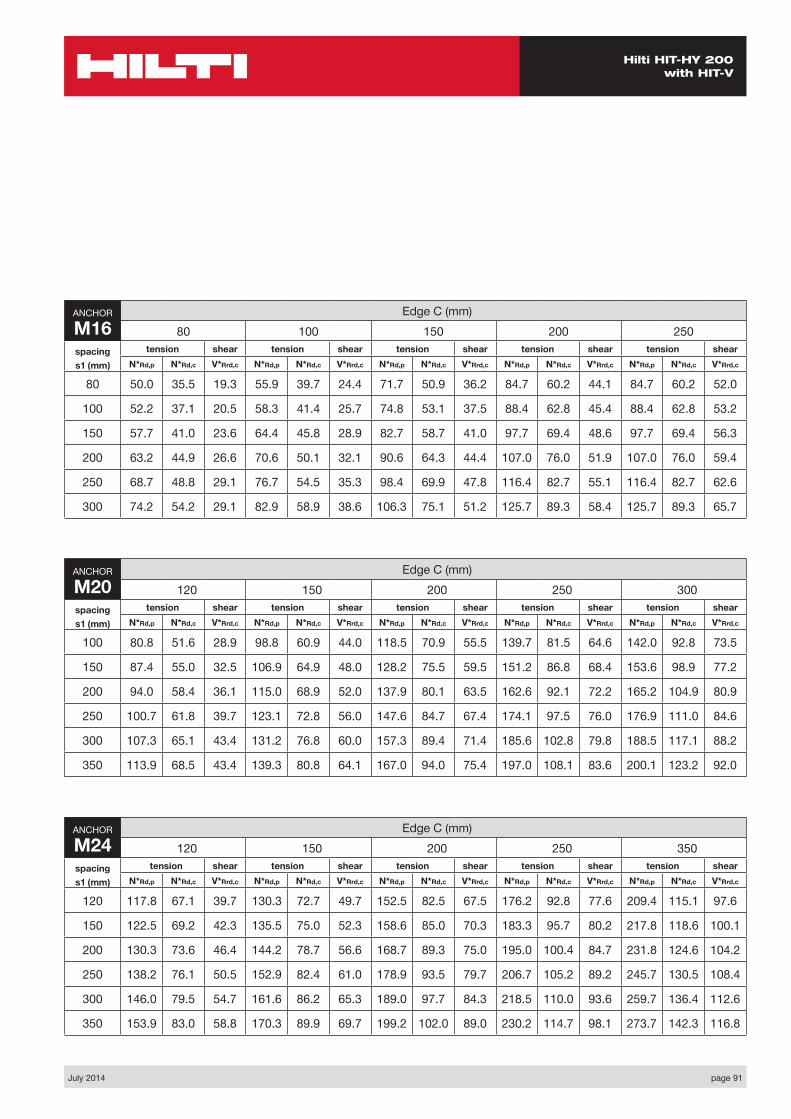
July 2014 page 91
Hilti HIT-HY 200 with HIT-V
ANCHOR
M24Edge C (mm)
120 150 200 250 350spacings1 (mm)
tension shear tension shear tension shear tension shear tension shearN*Rd,p N*Rd,c V*Rrd,c N*Rd,p N*Rd,c V*Rrd,c N*Rd,p N*Rd,c V*Rrd,c N*Rd,p N*Rd,c V*Rrd,c N*Rd,p N*Rd,c V*Rrd,c
120 117.8 67.1 39.7 130.3 72.7 49.7 152.5 82.5 67.5 176.2 92.8 77.6 209.4 115.1 97.6
150 122.5 69.2 42.3 135.5 75.0 52.3 158.6 85.0 70.3 183.3 95.7 80.2 217.8 118.6 100.1
200 130.3 73.6 46.4 144.2 78.7 56.6 168.7 89.3 75.0 195.0 100.4 84.7 231.8 124.6 104.2
250 138.2 76.1 50.5 152.9 82.4 61.0 178.9 93.5 79.7 206.7 105.2 89.2 245.7 130.5 108.4
300 146.0 79.5 54.7 161.6 86.2 65.3 189.0 97.7 84.3 218.5 110.0 93.6 259.7 136.4 112.6
350 153.9 83.0 58.8 170.3 89.9 69.7 199.2 102.0 89.0 230.2 114.7 98.1 273.7 142.3 116.8
ANCHOR
M16Edge C (mm)
80 100 150 200 250spacings1 (mm)
tension shear tension shear tension shear tension shear tension shearN*Rd,p N*Rd,c V*Rrd,c N*Rd,p N*Rd,c V*Rrd,c N*Rd,p N*Rd,c V*Rrd,c N*Rd,p N*Rd,c V*Rrd,c N*Rd,p N*Rd,c V*Rrd,c
80 50.0 35.5 19.3 55.9 39.7 24.4 71.7 50.9 36.2 84.7 60.2 44.1 84.7 60.2 52.0
100 52.2 37.1 20.5 58.3 41.4 25.7 74.8 53.1 37.5 88.4 62.8 45.4 88.4 62.8 53.2
150 57.7 41.0 23.6 64.4 45.8 28.9 82.7 58.7 41.0 97.7 69.4 48.6 97.7 69.4 56.3
200 63.2 44.9 26.6 70.6 50.1 32.1 90.6 64.3 44.4 107.0 76.0 51.9 107.0 76.0 59.4
250 68.7 48.8 29.1 76.7 54.5 35.3 98.4 69.9 47.8 116.4 82.7 55.1 116.4 82.7 62.6
300 74.2 54.2 29.1 82.9 58.9 38.6 106.3 75.1 51.2 125.7 89.3 58.4 125.7 89.3 65.7
ANCHOR
M20Edge C (mm)
120 150 200 250 300spacings1 (mm)
tension shear tension shear tension shear tension shear tension shearN*Rd,p N*Rd,c V*Rrd,c N*Rd,p N*Rd,c V*Rrd,c N*Rd,p N*Rd,c V*Rrd,c N*Rd,p N*Rd,c V*Rrd,c N*Rd,p N*Rd,c V*Rrd,c
100 80.8 51.6 28.9 98.8 60.9 44.0 118.5 70.9 55.5 139.7 81.5 64.6 142.0 92.8 73.5
150 87.4 55.0 32.5 106.9 64.9 48.0 128.2 75.5 59.5 151.2 86.8 68.4 153.6 98.9 77.2
200 94.0 58.4 36.1 115.0 68.9 52.0 137.9 80.1 63.5 162.6 92.1 72.2 165.2 104.9 80.9
250 100.7 61.8 39.7 123.1 72.8 56.0 147.6 84.7 67.4 174.1 97.5 76.0 176.9 111.0 84.6
300 107.3 65.1 43.4 131.2 76.8 60.0 157.3 89.4 71.4 185.6 102.8 79.8 188.5 117.1 88.2
350 113.9 68.5 43.4 139.3 80.8 64.1 167.0 94.0 75.4 197.0 108.1 83.6 200.1 123.2 92.0

page 92 July 2014
Hilti HIT-HY 200 with HIT-V
Four anchors Table 2: One edge influence – non cracked concrete
Design Data: fc,cyl=32 MPa
Anchor size M8 M10 M12 M16 M20 M24Typical embedment depth hef [mm] 80 90 110 125 170 210
Base material thickness h [mm] 110 120 150 200 250 300
ANCHOR
M8Edge C (mm)
40 80 100 150 200spacing
s1=s2 (mm)
tension shear tension shear tension shear tension shear tension shearN*Rd,p N*Rd,c V*Rrd,c N*Rd,p N*Rd,c V*Rrd,c N*Rd,p N*Rd,c V*Rrd,c N*Rd,p N*Rd,c V*Rrd,c N*Rd,p N*Rd,c V*Rrd,c
40 19.1 16.1 12.6 25.8 20.4 17.7 29.5 22.7 19.9 33.4 29.0 25.4 33.4 31.7 30.9
80 25.5 20.6 15.8 33.5 25.6 23.8 37.9 28.3 26.0 42.6 35.6 31.4 42.6 38.7 36.8
100 29.1 23.1 17.2 37.7 28.5 26.8 42.5 31.3 29.0 47.5 39.2 34.4 47.5 42.5 39.7
120 32.8 25.7 18.8 42.2 31.4 29.8 47.3 34.5 32.0 52.8 42.9 37.3 52.8 46.5 42.6
150 38.8 29.9 18.8 49.3 36.2 34.3 55.1 39.6 36.4 61.1 48.8 41.7 61.1 52.7 47.0
200 49.9 37.5 18.8 62.3 44.9 41.2 69.1 48.9 43.7 76.2 59.5 49.0 76.2 64.1 54.2
ANCHOR
M10Edge C (mm)
50 80 100 150 200spacing
s1=s2 (mm)
tension shear tension shear tension shear tension shear tension shearN*Rd,p N*Rd,c V*Rrd,c N*Rd,p N*Rd,c V*Rrd,c N*Rd,p N*Rd,c V*Rrd,c N*Rd,p N*Rd,c V*Rrd,c N*Rd,p N*Rd,c V*Rrd,c
50 26.3 19.9 17.4 32.1 23.2 21.0 36.2 25.5 23.4 44.1 31.8 29.3 44.1 38.4 35.1
100 36.9 25.9 22.6 44.1 29.8 29.2 49.3 32.5 31.5 59.0 39.8 37.2 59.0 47.5 43.0
150 49.2 32.6 27.0 58.0 37.1 37.2 64.3 40.2 39.4 76.0 48.7 45.1 76.0 57.6 50.7
200 63.3 40.0 27.0 73.8 45.2 45.0 81.3 48.8 47.2 95.2 58.5 52.8 95.2 68.6 58.4
250 79.1 48.2 27.0 91.5 54.1 49.6 100.2 58.2 54.8 116.5 69.2 60.5 116.5 80.6 66.0
300 85.9 57.2 27.0 99.1 63.8 49.9 108.4 68.5 59.8 125.7 80.8 68.0 125.7 93.6 73.5
ANCHOR
M12Edge C (mm)
60 80 100 150 200spacing
s1=s2 (mm)
tension shear tension shear tension shear tension shear tension shearN*Rd,p N*Rd,c V*Rrd,c N*Rd,p N*Rd,c V*Rrd,c N*Rd,p N*Rd,c V*Rrd,c N*Rd,p N*Rd,c V*Rrd,c N*Rd,p N*Rd,c V*Rrd,c
60 38.1 28.3 24.1 42.6 30.9 26.9 47.3 33.5 29.6 60.2 40.7 36.3 64.4 48.5 42.9
100 47.8 33.8 28.8 53.1 36.7 34.4 58.6 39.7 37.1 73.4 47.6 43.6 78.2 56.3 50.1
150 61.6 41.4 33.8 67.8 44.7 43.4 74.3 48.1 46.2 91.9 57.1 52.7 97.5 66.9 59.1
200 77.1 49.8 37.0 84.4 53.5 49.0 92.0 57.3 55.2 112.3 67.5 61.5 118.9 78.5 67.9
250 94.3 58.9 37.0 102.7 63.0 53.4 111.4 67.3 64.0 134.9 78.7 70.3 142.3 90.9 76.6
300 113.2 68.7 37.0 122.8 73.4 53.4 132.8 78.1 71.4 159.5 90.8 79.0 167.9 104.3 85.2
Nsd
Vsd
S2
S1
C
h

July 2014 page 93
Hilti HIT-HY 200 with HIT-V
ANCHOR
M24Edge C (mm)
120 150 200 250 350spacing
s1=s2 (mm)
tension shear tension shear tension shear tension shear tension shearN*Rd,p N*Rd,c V*Rrd,c N*Rd,p N*Rd,c V*Rrd,c N*Rd,p N*Rd,c V*Rrd,c N*Rd,p N*Rd,c V*Rrd,c N*Rd,p N*Rd,c V*Rrd,c
120 150.2 81.9 75.5 163.9 87.9 81.6 188.0 98.3 91.6 213.6 109.3 101.5 249.3 132.9 121.2
150 164.7 88.2 84.2 179.2 94.5 90.2 204.7 105.4 100.1 231.9 116.9 109.9 269.7 141.6 129.4
200 190.2 99.2 92.8 206.2 106.0 104.2 234.2 117.8 114.0 264.0 130.1 123.7 305.4 156.7 142.9
250 217.6 110.9 101.0 235.1 118.2 118.0 265.7 130.8 127.7 298.2 144.1 137.2 343.3 172.5 156.3
300 246.7 123.2 109.4 265.8 131.1 130.6 299.2 144.6 141.1 334.5 158.8 150.6 383.4 189.1 169.5
350 277.7 136.2 117.6 298.4 144.5 139.5 334.6 159.0 154.5 372.9 174.2 163.9 425.7 206.5 182.6
ANCHOR
M16Edge C (mm)
80 100 150 200 250spacing
s1=s2 (mm)
tension shear tension shear tension shear tension shear tension shearN*Rd,p N*Rd,c V*Rrd,c N*Rd,p N*Rd,c V*Rrd,c N*Rd,p N*Rd,c V*Rrd,c N*Rd,p N*Rd,c V*Rrd,c N*Rd,p N*Rd,c V*Rrd,c
80 65.0 46.2 37.8 71.4 50.7 40.9 88.7 63.0 48.8 102.8 73.0 56.6 102.8 73.0 64.3
100 71.8 51.0 41.0 78.6 55.8 45.4 97.0 68.9 53.2 112.0 79.6 60.9 112.0 79.6 68.6
150 90.1 64.0 47.2 98.1 69.7 56.3 119.4 84.2 64.0 136.8 97.2 71.5 136.8 97.2 79.1
200 110.5 78.5 53.2 119.7 84.4 64.1 144.2 100.3 74.5 164.1 116.6 82.0 164.1 116.6 89.5
250 133.0 93.2 58.0 143.4 100.0 70.6 171.4 117.9 85.0 193.9 137.2 92.4 193.9 137.8 99.7
300 157.5 109.3 58.0 169.3 116.8 77.2 200.8 136.8 95.3 226.2 158.4 102.6 226.2 160.7 110.0
ANCHOR
M20Edge C (mm)
100 150 200 250 300spacing
s1=s2 (mm)
tension shear tension shear tension shear tension shear tension shearN*Rd,p N*Rd,c V*Rrd,c N*Rd,p N*Rd,c V*Rrd,c N*Rd,p N*Rd,c V*Rrd,c N*Rd,p N*Rd,c V*Rrd,c N*Rd,p N*Rd,c V*Rrd,c
100 103.6 63.6 55.5 123.2 73.5 64.6 144.5 84.2 73.5 167.4 95.5 82.4 169.8 107.5 91.2
150 124.4 74.1 65.0 146.5 85.1 77.2 170.4 96.8 86.0 196.1 109.2 94.7 198.8 122.3 103.4
200 147.0 85.4 72.2 171.8 97.4 89.6 198.5 110.2 98.2 227.1 123.8 106.8 230.0 138.1 115.5
250 171.5 97.5 79.4 199.1 110.6 101.7 228.7 124.6 110.3 260.3 139.3 118.8 263.6 154.9 127.3
300 197.9 110.4 86.8 228.4 124.6 113.7 261.0 139.8 122.2 295.8 155.8 130.7 299.4 172.7 139.1
350 226.2 124.0 86.8 259.7 139.5 125.6 295.5 155.9 134.0 333.5 173.2 142.4 337.5 191.4 150.8
page 94 July 2014
Hilti HIT-HY 200 with HIT-V
Nsd
Vsd
S1
C
h
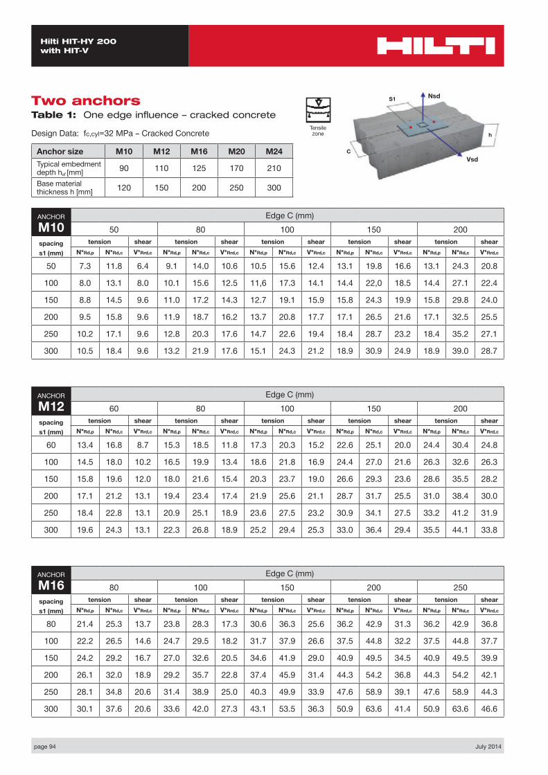
Two anchors Table 1: One edge influence – cracked concrete
Design Data: fc,cyl=32 MPa – Cracked Concrete
Anchor size M10 M12 M16 M20 M24Typical embedment depth hef [mm] 90 110 125 170 210
Base material thickness h [mm] 120 150 200 250 300
ANCHOR
M10Edge C (mm)
50 80 100 150 200spacings1 (mm)
tension shear tension shear tension shear tension shear tension shearN*Rd,p N*Rd,c V*Rrd,c N*Rd,p N*Rd,c V*Rrd,c N*Rd,p N*Rd,c V*Rrd,c N*Rd,p N*Rd,c V*Rrd,c N*Rd,p N*Rd,c V*Rrd,c
50 7.3 11.8 6.4 9.1 14.0 10.6 10.5 15.6 12.4 13.1 19.8 16.6 13.1 24.3 20.8
100 8.0 13.1 8.0 10.1 15.6 12.5 11,6 17.3 14.1 14.4 22,0 18.5 14.4 27.1 22.4
150 8.8 14.5 9.6 11.0 17.2 14.3 12.7 19.1 15.9 15.8 24.3 19.9 15.8 29.8 24.0
200 9.5 15.8 9.6 11.9 18.7 16.2 13.7 20.8 17.7 17.1 26.5 21.6 17.1 32.5 25.5
250 10.2 17.1 9.6 12.8 20.3 17.6 14.7 22.6 19.4 18.4 28.7 23.2 18.4 35.2 27.1
300 10.5 18.4 9.6 13.2 21.9 17.6 15.1 24.3 21.2 18.9 30.9 24.9 18.9 39.0 28.7
ANCHOR
M12Edge C (mm)
60 80 100 150 200spacings1 (mm)
tension shear tension shear tension shear tension shear tension shearN*Rd,p N*Rd,c V*Rrd,c N*Rd,p N*Rd,c V*Rrd,c N*Rd,p N*Rd,c V*Rrd,c N*Rd,p N*Rd,c V*Rrd,c N*Rd,p N*Rd,c V*Rrd,c
60 13.4 16.8 8.7 15.3 18.5 11.8 17.3 20.3 15.2 22.6 25.1 20.0 24.4 30.4 24.8
100 14.5 18.0 10.2 16.5 19.9 13.4 18.6 21.8 16.9 24.4 27.0 21.6 26.3 32.6 26.3
150 15.8 19.6 12.0 18.0 21.6 15.4 20.3 23.7 19.0 26.6 29.3 23.6 28.6 35.5 28.2
200 17.1 21.2 13.1 19.4 23.4 17.4 21.9 25.6 21.1 28.7 31.7 25.5 31.0 38.4 30.0
250 18.4 22.8 13.1 20.9 25.1 18.9 23.6 27.5 23.2 30.9 34.1 27.5 33.2 41.2 31.9
300 19.6 24.3 13.1 22.3 26.8 18.9 25.2 29.4 25.3 33.0 36.4 29.4 35.5 44.1 33.8
ANCHOR
M16Edge C (mm)
80 100 150 200 250spacings1 (mm)
tension shear tension shear tension shear tension shear tension shearN*Rd,p N*Rd,c V*Rrd,c N*Rd,p N*Rd,c V*Rrd,c N*Rd,p N*Rd,c V*Rrd,c N*Rd,p N*Rd,c V*Rrd,c N*Rd,p N*Rd,c V*Rrd,c
80 21.4 25.3 13.7 23.8 28.3 17.3 30.6 36.3 25.6 36.2 42.9 31.3 36.2 42.9 36.8
100 22.2 26.5 14.6 24.7 29.5 18.2 31.7 37.9 26.6 37.5 44.8 32.2 37.5 44.8 37.7
150 24.2 29.2 16.7 27.0 32.6 20.5 34.6 41.9 29.0 40.9 49.5 34.5 40.9 49.5 39.9
200 26.1 32.0 18.9 29.2 35.7 22.8 37.4 45.9 31.4 44.3 54.2 36.8 44.3 54.2 42.1
250 28.1 34.8 20.6 31.4 38.9 25.0 40.3 49.9 33.9 47.6 58.9 39.1 47.6 58.9 44.3
300 30.1 37.6 20.6 33.6 42.0 27.3 43.1 53.5 36.3 50.9 63.6 41.4 50.9 63.6 46.6
Tensile zone

July 2014 page 95
Hilti HIT-HY 200 with HIT-V
ANCHOR
M24Edge C (mm)
120 150 200 250 350spacings1 (mm)
tension shear tension shear tension shear tension shear tension shearN*Rd,p N*Rd,c V*Rrd,c N*Rd,p N*Rd,c V*Rrd,c N*Rd,p N*Rd,c V*Rrd,c N*Rd,p N*Rd,c V*Rrd,c N*Rd,p N*Rd,c V*Rrd,c
120 48.5 47.8 28.2 53.7 51.8 35.2 62.8 58.8 47.8 72.6 66.1 55.0 86.3 82.0 69.1
150 50.3 49.3 29.9 55.7 53.4 37.0 65.2 60.6 49.8 75.3 68.2 56.9 89.5 84.6 70.9
200 53.4 51.8 32.9 59.0 56.1 40.1 69.1 63.6 53.1 78.9 71.6 60.0 94.9 88.8 73.9
250 56.4 54.2 35.8 62.4 58.8 43.2 73.0 66.7 56.4 84.4 75.0 63.2 100.3 93.0 76.8
300 59.4 56.7 38.8 65.7 61.4 46.3 76.9 69.7 59.8 88.9 78.4 66.3 105.6 97.2 79.8
350 62.4 59.2 41.7 69.0 64.1 49.4 80.8 72.7 63.1 93.4 81.8 69.5 111.0 101.5 82.7
ANCHOR
M20Edge C (mm)
100 150 200 250 300spacings1 (mm)
tension shear tension shear tension shear tension shear tension shearN*Rd,p N*Rd,c V*Rrd,c N*Rd,p N*Rd,c V*Rrd,c N*Rd,p N*Rd,c V*Rrd,c N*Rd,p N*Rd,c V*Rrd,c N*Rd,p N*Rd,c V*Rrd,c
100 34.0 36.8 20.5 41.6 43.4 31.2 49.8 50.5 39.4 58.8 58.1 45.8 59.7 66.1 52.1
150 36.5 39.2 23.1 44.6 46.2 34.0 53.5 53.8 42.2 63.1 61.9 48.5 64.1 70.5 54.7
200 38.9 41.6 25.6 47.6 49.1 36.9 57.1 57.1 45.0 67.3 65.7 51.1 68.4 74.8 57.3
250 41.4 44.0 28.2 50.6 51.9 39.7 60.7 60.4 47.8 71.6 69.5 53.8 72.7 79.1 60.0
300 43.8 46.4 30.7 53.6 54.8 42.6 64.3 63.7 50.6 75.8 73.3 56.5 77.0 83.5 62.5
350 46.3 48.8 30.7 56.6 57.6 45.4 67.9 67.0 53.4 80.1 77.1 59.2 81.3 87.8 65.1

page 96 July 2014
Hilti HIT-HY 200 with HIT-V
Four anchors Table 2: One edge influence – cracked concrete
Design Data: fc,cyl=32 MPa– Cracked Concrete
Anchor size M10 M12 M16 M20 M24Typical embedment depth hef [mm] 90 110 125 170 210
Base material thickness h [mm] 120 150 200 250 300
ANCHOR
M10Edge C (mm)
50 80 100 150 200spacing
s1=s2 (mm)
tension shear tension shear tension shear tension shear tension shearN*Rd,p N*Rd,c V*Rrd,c N*Rd,p N*Rd,c V*Rrd,c N*Rd,p N*Rd,c V*Rrd,c N*Rd,p N*Rd,c V*Rrd,c N*Rd,p N*Rd,c V*Rrd,c
50 11.1 14.2 12.4 13.5 16.5 14.9 15.3 18.2 16.6 18.6 22.7 20.8 18.6 27.4 24.9
100 14.1 18.4 16.0 16.9 21.2 20.7 18.9 23.2 22.4 22.6 28.4 26.4 22.6 33.9 30.4
150 17.4 23.2 19.1 20.6 26.4 26.4 22.8 28.7 28.0 26.9 34.7 32.0 26.9 41.1 35.9
200 20.9 28.5 19.1 24.3 32.2 31.9 26.8 34.8 33.5 31.4 41.7 37.4 31.4 48.9 41.4
250 24.4 34.4 19.1 28.2 38.6 35.2 30.9 41.5 38.8 35.9 49.3 42.9 35.9 57.5 46.8
300 25.8 40.8 19.1 29.7 45.5 35.2 32.5 48.8 42.4 37.7 57.6 48.2 37.7 66.7 52.1
ANCHOR
M12Edge C (mm)
60 80 100 150 200spacing
s1=s2 (mm)
tension shear tension shear tension shear tension shear tension shearN*Rd,p N*Rd,c V*Rrd,c N*Rd,p N*Rd,c V*Rrd,c N*Rd,p N*Rd,c V*Rrd,c N*Rd,p N*Rd,c V*Rrd,c N*Rd,p N*Rd,c V*Rrd,c
60 19.6 20.2 17.1 21.9 22.0 19.1 24.4 23.9 21.0 31.0 29.0 25.7 33.1 34.6 30.4
100 23.4 24.1 20.4 26.0 26.2 24.4 28.7 28.3 26.3 36.0 34.0 30.9 38.3 40.1 35.6
150 28.7 29.5 24.0 31.6 31.9 30.8 34.6 34.3 32.8 42.7 40.7 37.3 45.4 47.7 41.9
200 34.3 35.5 26.2 37.5 38.1 34.7 40.9 40.9 39.1 49.9 48.1 43.6 52.8 55.9 48.1
250 40.2 42.0 26.2 43.8 44.9 37.9 47.5 48.0 45.4 57.5 56.1 49.8 60.6 64.8 54.3
300 46.3 49.0 26.2 50.3 52.3 37.9 54.4 55.7 50.6 65.3 64.7 56.0 68.7 74.4 60.4
ANCHOR
M16Edge C (mm)
80 100 150 200 250spacing
s1=s2 (mm)
tension shear tension shear tension shear tension shear tension shearN*Rd,p N*Rd,c V*Rrd,c N*Rd,p N*Rd,c V*Rrd,c N*Rd,p N*Rd,c V*Rrd,c N*Rd,p N*Rd,c V*Rrd,c N*Rd,p N*Rd,c V*Rrd,c
80 30.2 34.3 26.8 33.2 37.4 29.0 41.2 44.9 34.6 47.8 52.0 40.1 47.8 52.0 45.6
100 32.9 36.3 29.2 36.0 39.8 32.2 44.5 49.1 37.7 51.3 56.7 43.2 51.3 56.7 48.6
150 40.0 45.6 33.5 43.6 49.7 39.9 53.1 60.0 45.3 60.8 69.3 50.7 60.8 69.3 56.0
200 47.8 55.9 37.7 51.8 60.2 45.5 62.4 71.5 52.8 71.0 83.1 58.1 71.0 83.1 63.4
250 56.1 66.5 41.2 60.5 71.3 50.1 72.3 84.0 60.2 81.9 97.8 65.4 81.9 98.2 70.7
300 65.0 77.9 41.2 69.9 83.3 54.6 82.9 97.5 67.5 93.4 112.9 72.7 93.4 114.6 77.9
Nsd
Vsd
S2
S1
C
h
Tensile zone

July 2014 page 97
Hilti HIT-HY 200 with HIT-V
ANCHOR
M24Edge C (mm)
120 150 200 250 350spacing
s1=s2 (mm)
tension shear tension shear tension shear tension shear tension shearN*Rd,p N*Rd,c V*Rrd,c N*Rd,p N*Rd,c V*Rrd,c N*Rd,p N*Rd,c V*Rrd,c N*Rd,p N*Rd,c V*Rrd,c N*Rd,p N*Rd,c V*Rrd,c
120 64.5 58.4 53.5 70.4 62.6 57.8 80.7 70.1 64.9 91.7 77.9 72.0 107.1 94.7 85.9
150 70.3 62.9 59.7 76.5 67.3 63.9 87.4 75.1 70.9 99.0 83.3 77.9 115.1 100.9 91.7
200 80.4 70.8 65.8 87.2 75.6 73.9 99.0 84.0 80.8 111.6 92.8 87.6 129.1 111.7 101.2
250 91.2 79.1 71.6 98.6 84.3 83.6 111.4 93.3 90.4 125.1 102.7 97.2 143.9 123.0 110.7
300 102.7 87.9 77.5 110.6 93.4 92.6 124.5 103.1 100.0 139.2 113.2 106.7 159.6 134.8 120.1
350 114.8 97.1 83.4 123.3 103.0 98.8 138.3 113.4 109.5 154.1 124.2 116.1 176.0 147.2 129.4
ANCHOR
M20Edge C (mm)
100 150 200 250 300spacing
s1=s2 (mm)
tension shear tension shear tension shear tension shear tension shearN*Rd,p N*Rd,c V*Rrd,c N*Rd,p N*Rd,c V*Rrd,c N*Rd,p N*Rd,c V*Rrd,c N*Rd,p N*Rd,c V*Rrd,c N*Rd,p N*Rd,c V*Rrd,c
100 46.6 45.3 39.4 55.5 52.4 45.8 65.0 60.0 52.1 75.4 68.1 58.4 76.4 76.6 64.6
150 54.9 52.8 46.1 64.6 60.6 54.7 75.2 69.0 60.9 86.5 77.8 67.1 87.7 87.2 73.3
200 63.8 60.9 51.2 74.5 69.5 63.5 86.1 78.6 69.6 98.5 88.3 75.7 99.8 98.5 81.8
250 73.3 69.5 56.4 85.0 78.9 72.1 97.6 88.8 78.2 111.1 99.3 84.2 112.6 110.4 90.2
300 83.3 78.7 61.5 96.1 88.9 80.6 109.9 99.7 86.6 124.5 111.1 92.6 126.0 123.1 98.5
350 94.0 88.4 61.5 107.9 99.4 89.0 122.7 111.1 95.0 138.6 123.4 100.9 140.2 136.4 106.8
page 98 July 2014
Hilti HIT-HY 200 with HIT-V
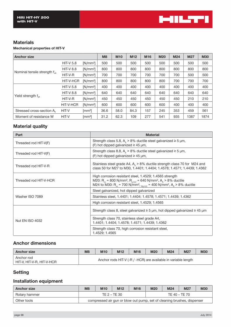
MaterialsMechanical properties of HIT-V
Anchor size M8 M10 M12 M16 M20 M24 M27 M30
Nominal tensile strength fuk
HIT-V 5.8 [N/mm²] 500 500 500 500 500 500 500 500HIT-V 8.8 [N/mm²] 800 800 800 800 800 800 800 800HIT-V-R [N/mm²] 700 700 700 700 700 700 500 500HIT-V-HCR [N/mm²] 800 800 800 800 800 700 700 700
Yield strength fyk
HIT-V 5.8 [N/mm²] 400 400 400 400 400 400 400 400HIT-V 8.8 [N/mm²] 640 640 640 640 640 640 640 640HIT-V-R [N/mm²] 450 450 450 450 450 450 210 210
HIT-V-HCR [N/mm²] 600 600 600 600 600 400 400 400Stressed cross-section As HIT-V [mm²] 36.6 58.0 84.3 157 245 353 459 561Moment of resistance W HIT-V [mm³] 31.2 62.3 109 277 541 935 1387 1874
Material quality
Part Material
Threaded rod HIT-V(F) Strength class 5.8, A5 > 8% ductile steel galvanized ≥ 5 μm, (F) hot dipped galvanized ≥ 45 μm,
Threaded rod HIT-V(F) Strength class 8.8, A5 > 8% ductile steel galvanized ≥ 5 μm,(F) hot dipped galvanized ≥ 45 μm,
Threaded rod HIT-V-R Stainless steel grade A4, A5 > 8% ductile strength class 70 for M24 and class 50 for M27 to M30, 1.4401; 1.4404; 1.4578; 1.4571; 1.4439; 1.4362
Threaded rod HIT-V-HCRHigh corrosion resistant steel, 1.4529; 1.4565 strength M20: Rm = 800 N/mm², Rp 0.2 = 640 N/mm², A5 > 8% ductile M24 to M30: Rm = 700 N/mm², Rp 0.2 = 400 N/mm², A5 > 8% ductile
Washer ISO 7089Steel galvanized, hot dipped galvanizedStainless steel, 1.4401; 1.4404; 1.4578; 1.4571; 1.4439; 1.4362High corrosion resistant steel, 1.4529; 1.4565
Nut EN ISO 4032
Strength class 8, steel galvanized ≥ 5 μm, hot dipped galvanized ≥ 45 μm
Strength class 70, stainless steel grade A4, 1.4401; 1.4404; 1.4578; 1.4571; 1.4439; 1.4362Strength class 70, high corrosion resistant steel, 1.4529; 1.4565
Anchor dimensions
Anchor size M8 M10 M12 M16 M20 M24 M27 M30Anchor rod HIT-V, HIT-V-R, HIT-V-HCR Anchor rods HIT-V (-R / -HCR) are available in variable length
Setting
Installation equipmentAnchor size M8 M10 M12 M16 M20 M24 M27 M30Rotary hammer TE 2 – TE 30 TE 40 – TE 70Other tools compressed air gun or blow out pump, set of cleaning brushes, dispenser
July 2014 page 99
Hilti HIT-HY 200 with HIT-V
Setting instructions
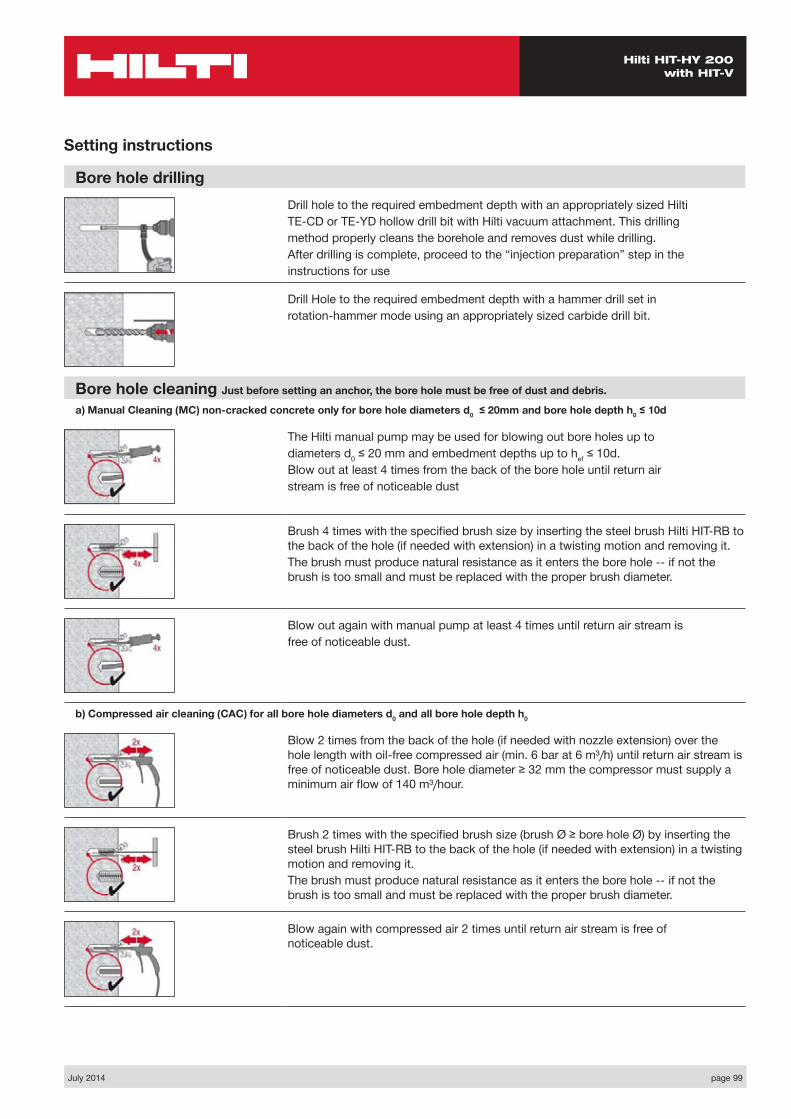
Bore hole drillingDrill hole to the required embedment depth with an appropriately sized HiltiTE-CD or TE-YD hollow drill bit with Hilti vacuum attachment. This drillingmethod properly cleans the borehole and removes dust while drilling.After drilling is complete, proceed to the “injection preparation” step in theinstructions for use
Drill Hole to the required embedment depth with a hammer drill set inrotation-hammer mode using an appropriately sized carbide drill bit.
Bore hole cleaning Just before setting an anchor, the bore hole must be free of dust and debris.
a) Manual Cleaning (MC) non-cracked concrete only for bore hole diameters d0 ≤ 20mm and bore hole depth h0 ≤ 10d
The Hilti manual pump may be used for blowing out bore holes up todiameters d0 ≤ 20 mm and embedment depths up to hef ≤ 10d.Blow out at least 4 times from the back of the bore hole until return airstream is free of noticeable dust
Brush 4 times with the specified brush size by inserting the steel brush Hilti HIT-RB to the back of the hole (if needed with extension) in a twisting motion and removing it.The brush must produce natural resistance as it enters the bore hole -- if not the brush is too small and must be replaced with the proper brush diameter.
Blow out again with manual pump at least 4 times until return air stream isfree of noticeable dust.
b) Compressed air cleaning (CAC) for all bore hole diameters d0 and all bore hole depth h0
Blow 2 times from the back of the hole (if needed with nozzle extension) over the hole length with oil-free compressed air (min. 6 bar at 6 m³/h) until return air stream is free of noticeable dust. Bore hole diameter ≥ 32 mm the compressor must supply a minimum air flow of 140 m³/hour.
Brush 2 times with the specified brush size (brush Ø ≥ bore hole Ø) by inserting the steel brush Hilti HIT-RB to the back of the hole (if needed with extension) in a twisting motion and removing it.The brush must produce natural resistance as it enters the bore hole -- if not the brush is too small and must be replaced with the proper brush diameter.
Blow again with compressed air 2 times until return air stream is free of noticeable dust.
page 100 July 2014
Hilti HIT-HY 200 with HIT-V
Setting instructions
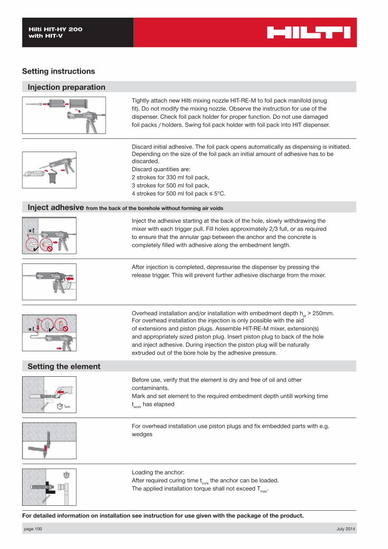
Injection preparationTightly attach new Hilti mixing nozzle HIT-RE-M to foil pack manifold (snugfit). Do not modify the mixing nozzle. Observe the instruction for use of thedispenser. Check foil pack holder for proper function. Do not use damagedfoil packs / holders. Swing foil pack holder with foil pack into HIT dispenser.
Discard initial adhesive. The foil pack opens automatically as dispensing is initiated. Depending on the size of the foil pack an initial amount of adhesive has to be discarded.Discard quantities are:2 strokes for 330 ml foil pack,3 strokes for 500 ml foil pack,4 strokes for 500 ml foil pack ≤ 5°C.
Inject adhesive from the back of the borehole without forming air voids
Inject the adhesive starting at the back of the hole, slowly withdrawing themixer with each trigger pull. Fill holes approximately 2/3 full, or as requiredto ensure that the annular gap between the anchor and the concrete iscompletely filled with adhesive along the embedment length.
After injection is completed, depressurise the dispenser by pressing therelease trigger. This will prevent further adhesive discharge from the mixer.
Overhead installation and/or installation with embedment depth hef > 250mm. For overhead installation the injection is only possible with the aidof extensions and piston plugs. Assemble HIT-RE-M mixer, extension(s)and appropriately sized piston plug. Insert piston plug to back of the holeand inject adhesive. During injection the piston plug will be naturallyextruded out of the bore hole by the adhesive pressure.
Setting the elementBefore use, verify that the element is dry and free of oil and othercontaminants.Mark and set element to the required embedment depth untill working timetwork has elapsed
For overhead installation use piston plugs and fix embedded parts with e.g.wedges
Loading the anchor:After required curing time tcure the anchor can be loaded.The applied installation torque shall not exceed Tmax.
For detailed information on installation see instruction for use given with the package of the product.
July 2014 page 101
Hilti HIT-HY 200 with HIT-V
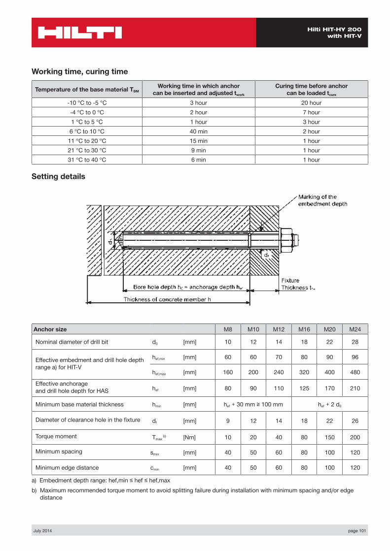
Anchor size M8 M10 M12 M16 M20 M24
Nominal diameter of drill bit d0 [mm] 10 12 14 18 22 28
Effective embedment and drill hole depth range a) for HIT-V
hef,min [mm] 60 60 70 80 90 96
hef,max [mm] 160 200 240 320 400 480
Effective anchorage and drill hole depth for HAS hef [mm] 80 90 110 125 170 210
Minimum base material thickness hmin [mm] hef + 30 mm ≥ 100 mm hef + 2 d0
Diameter of clearance hole in the fixture df [mm] 9 12 14 18 22 26
Torque moment Tmax b) [Nm] 10 20 40 80 150 200
Minimum spacing smin [mm] 40 50 60 80 100 120
Minimum edge distance cmin [mm] 40 50 60 80 100 120
a) Embedment depth range: hef,min ≤ hef ≤ hef,max b) Maximum recommended torque moment to avoid splitting failure during installation with minimum spacing and/or edge
distance
Setting details
Working time, curing time
Temperature of the base material TBMWorking time in which anchor
can be inserted and adjusted twork
Curing time before anchor can be loaded tcure
-10 °C to -5 °C 3 hour 20 hour-4 °C to 0 °C 2 hour 7 hour1 °C to 5 °C 1 hour 3 hour6 °C to 10 °C 40 min 2 hour
11 °C to 20 °C 15 min 1 hour21 °C to 30 °C 9 min 1 hour31 °C to 40 °C 6 min 1 hour
page 102 July 2014
Hilti HIT-HY 200 with HIS-(R)N
Hilti HIT-HY 200 with HIS-(R)N
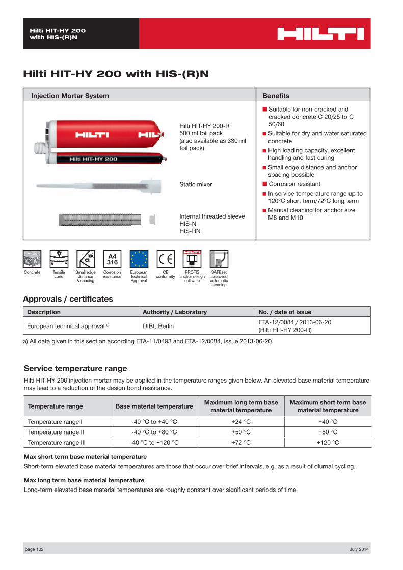
Injection Mortar System Benefits
■ Suitable for non-cracked and cracked concrete C 20/25 to C 50/60
■ Suitable for dry and water saturated concrete
■ High loading capacity, excellent handling and fast curing
■ Small edge distance and anchor spacing possible
■ Corrosion resistant■ In service temperature range up to
120°C short term/72°C long term■ Manual cleaning for anchor size
M8 and M10
Approvals / certificatesDescription Authority / Laboratory No. / date of issue
European technical approval a) DIBt, Berlin ETA-12/0084 / 2013-06-20 (Hilti HIT-HY 200-R)
a) All data given in this section according ETA-11/0493 and ETA-12/0084, issue 2013-06-20.
Service temperature rangeHilti HIT-HY 200 injection mortar may be applied in the temperature ranges given below. An elevated base material temperature may lead to a reduction of the design bond resistance.
Temperature range Base material temperature Maximum long term base material temperature
Maximum short term base material temperature
Temperature range I -40 °C to +40 °C +24 °C +40 °CTemperature range II -40 °C to +80 °C +50 °C +80 °CTemperature range III -40 °C to +120 °C +72 °C +120 °C
Max short term base material temperatureShort-term elevated base material temperatures are those that occur over brief intervals, e.g. as a result of diurnal cycling.
Max long term base material temperatureLong-term elevated base material temperatures are roughly constant over significant periods of time
Hilti HIT-HY 200-R500 ml foil pack(also available as 330 ml foil pack)
Static mixer
CE conformity
Small edge distance
& spacing
European Technical Approval
Concrete
A4 316
Corrosion resistance
Tensile zone
PROFIS anchor design
software
Internal threaded sleeve HIS-N HIS-RN
SAFEset approved automatic cleaning
July 2014 page 103
Hilti HIT-HY 200 with HIS-(R)N
Design process for typical anchor layoutsThe design values in the tables are obtained from Profis V2.2.1 in compliance with the design method according to EOTA TR 029. Design resistance according to data given in ETA-12/0084, issue 2013-06-20.■ Influence of concrete strength ■ Influence of edge distance ■ Influence of spacing
The design method is based on the following simplification:■ No different loads are acting on individual anchors (no eccentricity)
The values are valid for the anchor configuration.
For more complex fastening applications please use the anchor design software PROFIS Anchor.
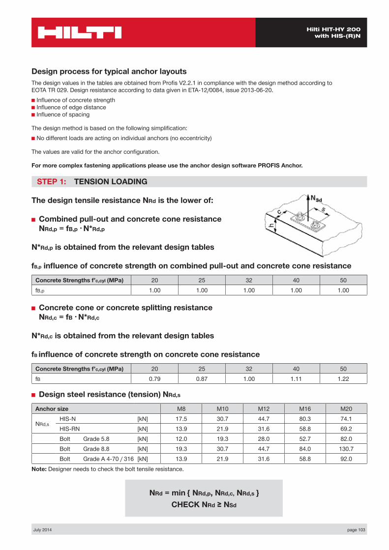
STEP 1: TENSION LOADING
The design tensile resistance NRd is the lower of:
■ Combined pull-out and concrete cone resistance NRd,p = fB,p • N*Rd,p
N*Rd,p is obtained from the relevant design tables
fB,p influence of concrete strength on combined pull-out and concrete cone resistance
Concrete Strengths f’c,cyl (MPa) 20 25 32 40 50fB,p 1.00 1.00 1.00 1.00 1.00
■ Concrete cone or concrete splitting resistance NRd,c = fB • N*Rd,c
N*Rd,c is obtained from the relevant design tables
fB influence of concrete strength on concrete cone resistance
Concrete Strengths f’c,cyl (MPa) 20 25 32 40 50fB 0.79 0.87 1.00 1.11 1.22
■ Design steel resistance (tension) NRd,s
Anchor size M8 M10 M12 M16 M20
NRd,sHIS-N [kN] 17.5 30.7 44.7 80.3 74.1HIS-RN [kN] 13.9 21.9 31.6 58.8 69.2Bolt Grade 5.8 [kN] 12.0 19.3 28.0 52.7 82.0Bolt Grade 8.8 [kN] 19.3 30.7 44.7 84.0 130.7Bolt Grade A 4-70 / 316 [kN] 13.9 21.9 31.6 58.8 92.0
Note: Designer needs to check the bolt tensile resistance.
NRd = min { NRd,p, NRd,c, NRd,s } CHECK NRd ≥ NSd
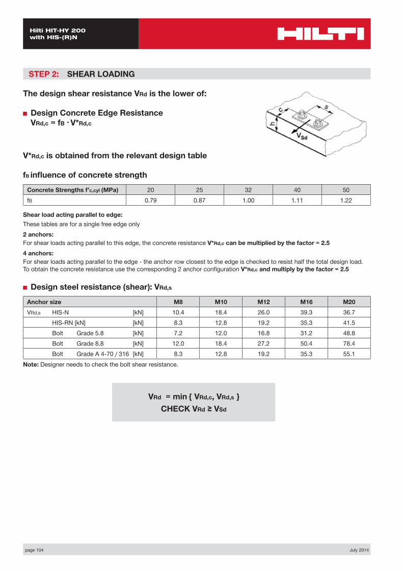
page 104 July 2014
Hilti HIT-HY 200 with HIS-(R)N
STEP 2: SHEAR LOADING
The design shear resistance VRd is the lower of:
■ Design Concrete Edge Resistance VRd,c = fB • V*Rd,c
V*Rd,c is obtained from the relevant design table
fB influence of concrete strength
Concrete Strengths f’c,cyl (MPa) 20 25 32 40 50fB 0.79 0.87 1.00 1.11 1.22
Shear load acting parallel to edge:These tables are for a single free edge only2 anchors:For shear loads acting parallel to this edge, the concrete resistance V*Rd,c can be multiplied by the factor = 2.54 anchors:For shear loads acting parallel to the edge - the anchor row closest to the edge is checked to resist half the total design load. To obtain the concrete resistance use the corresponding 2 anchor configuration V*Rd,c and multiply by the factor = 2.5
■ Design steel resistance (shear): VRd,s
Anchor size M8 M10 M12 M16 M20VRd,s HIS-N [kN] 10.4 18.4 26.0 39.3 36.7
HIS-RN [kN] [kN] 8.3 12.8 19.2 35.3 41.5Bolt Grade 5.8 [kN] 7.2 12.0 16.8 31.2 48.8Bolt Grade 8.8 [kN] 12.0 18.4 27.2 50.4 78.4Bolt Grade A 4-70 / 316 [kN] 8.3 12.8 19.2 35.3 55.1
Note: Designer needs to check the bolt shear resistance.
VRd = min { VRd,c, VRd,s } CHECK VRd ≥ VSd

July 2014 page 105
Hilti HIT-HY 200 with HIS-(R)N
STEP 3: COMBINED TENSION AND SHEAR LOADING
The following equations must be satisfied:
NSd/NRd + VSd/VRd ≤ 1.2
and
NSd/NRd ≤ 1, VSd/VRd ≤ 1
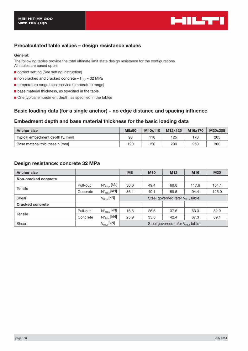
page 106 July 2014
Hilti HIT-HY 200 with HIS-(R)N
Basic loading data (for a single anchor) – no edge distance and spacing influence
Embedment depth and base material thickness for the basic loading data
Anchor size M8x90 M10x110 M12x125 M16x170 M20x205
Typical embedment depth hef [mm] 90 110 125 170 205
Base material thickness h [mm] 120 150 200 250 300
Precalculated table values – design resistance values
General:The following tables provide the total ultimate limit state design resistance for the configurations. All tables are based upon:■ correct setting (See setting instruction)■ non cracked and cracked concrete – fc,cyl = 32 MPa■ temperature range I (see service temperature range)■ base material thickness, as specified in the table■ One typical embedment depth, as specified in the tables
Design resistance: concrete 32 MPa
Anchor size M8 M10 M12 M16 M20Non-cracked concrete
Tensile Pull-out N*Rd,p [kN] 30.6 49.4 69.8 117.6 154.1Concrete N*Rd,c [kN] 36.4 49.1 59.5 94.4 125.0
Shear VRd,s [kN] Steel governed refer VRd,s tableCracked concrete
Tensile Pull-out N*Rd,p [kN] 16.5 26.6 37.6 63.3 82.9Concrete N*Rd,c [kN] 25.9 35.0 42.4 67.3 89.1
Shear VRd,s [kN] Steel governed refer VRd,s table
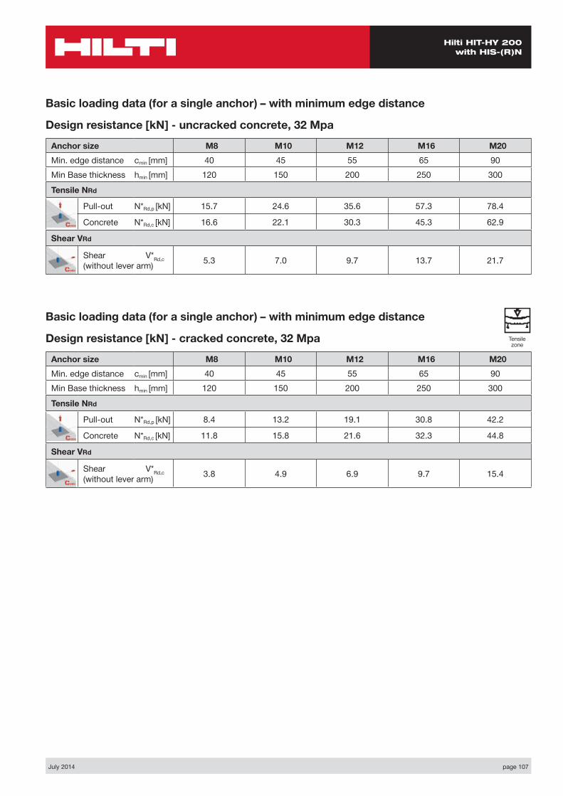
July 2014 page 107
Hilti HIT-HY 200 with HIS-(R)N
Basic loading data (for a single anchor) – with minimum edge distance
Design resistance [kN] - uncracked concrete, 32 Mpa
Anchor size M8 M10 M12 M16 M20Min. edge distance cmin [mm] 40 45 55 65 90Min Base thickness hmin [mm] 120 150 200 250 300
Tensile NRd
Pull-out N*Rd,p [kN] 15.7 24.6 35.6 57.3 78.4
Concrete N*Rd,c [kN] 16.6 22.1 30.3 45.3 62.9
Shear VRd
Shear V*Rd,c (without lever arm) 5.3 7.0 9.7 13.7 21.7
Basic loading data (for a single anchor) – with minimum edge distance
Design resistance [kN] - cracked concrete, 32 Mpa
Anchor size M8 M10 M12 M16 M20Min. edge distance cmin [mm] 40 45 55 65 90Min Base thickness hmin [mm] 120 150 200 250 300
Tensile NRd
Pull-out N*Rd,p [kN] 8.4 13.2 19.1 30.8 42.2
Concrete N*Rd,c [kN] 11.8 15.8 21.6 32.3 44.8
Shear VRd
Shear V*Rd,c (without lever arm) 3.8 4.9 6.9 9.7 15.4
Tensile zone

page 108 July 2014
Hilti HIT-HY 200 with HIS-(R)N
N*
V*
S1
C
h
Two anchors Table 1: One edge influence – non cracked concrete
Design Data: fc=32 MPa
Anchor size M8 M10 M12 M16 M20Min Slab depth 120 150 200 250 300Embedment Depth 90 110 125 170 205
ANCHOR
M8Edge C (mm)
40 80 100 150 200spacings1 (mm)
tension shear tension shear tension shear tension shear tension shearN*Rd,p N*Rd,c V*Rrd,c N*Rd,p N*Rd,c V*Rrd,c N*Rd,p N*Rd,c V*Rrd,c N*Rd,p N*Rd,c V*Rrd,c N*Rd,p N*Rd,c V*Rrd,c
40 19.0 18.3 7.1 26.0 23.1 15.1 29.8 25.7 17.5 37.2 32.6 23.6 37.2 40.0 29.6
80 21.2 20.0 8.9 28.9 25.2 17.2 33.2 28.0 19.6 41.4 35.6 25.6 41.4 43.7 31.5
100 22.2 20.8 9.8 30.4 26.3 18.3 34.9 29.2 20.6 43.5 37.1 26.5 43.5 45.5 32.4
150 24.9 22.9 10.7 34.1 28.9 21.0 39.1 32.1 23.2 48.8 40.9 28.9 48.8 50.1 34.7
200 27.6 25.0 10.7 37.8 31.5 23.7 43.3 35.1 25.8 54.0 44.6 31.4 54.0 54.7 37.0
ANCHOR
M10Edge C (mm)
45 80 100 150 200spacings1 (mm)
tension shear tension shear tension shear tension shear tension shearN*Rd,p N*Rd,c V*Rrd,c N*Rd,p N*Rd,c V*Rrd,c N*Rd,p N*Rd,c V*Rrd,c N*Rd,p N*Rd,c V*Rrd,c N*Rd,p N*Rd,c V*Rrd,c
45 27.9 24.3 9.3 35.3 28.9 16.8 39.8 31.7 21.7 52.1 39.2 28.7 56.2 47.4 35.6
80 30.5 25.9 11.1 38.5 30.8 18.9 43.5 33.8 23.9 57.0 41.9 30.8 61.4 50.6 37.6
100 32.0 26.8 12.1 40.4 32.0 20.1 45.6 35.1 25.1 59.8 43.4 31.9 64.4 52.5 38.7
150 35.8 29.2 13.9 45.1 34.8 23.0 50.9 38.1 28.3 66.7 47.2 34.8 71.9 57.1 41.4
200 39.5 31.5 13.9 49.8 37.5 26.0 56.2 41.2 31.4 73.7 51.0 37.7 79.4 61.7 44.2
250 43.2 33.9 13.9 54.5 40.3 28.3 61.5 44.3 34.6 80.6 54.7 40.6 86.9 66.2 47.0
ANCHOR
M12Edge C (mm)
55 80 100 150 200spacings1 (mm)
tension shear tension shear tension shear tension shear tension shearN*Rd,p N*Rd,c V*Rrd,c N*Rd,p N*Rd,c V*Rrd,c N*Rd,p N*Rd,c V*Rrd,c N*Rd,p N*Rd,c V*Rrd,c N*Rd,p N*Rd,c V*Rrd,c
55 40.8 34.8 12.9 47.3 40.3 18.8 52.7 45.0 23.9 67.7 57.7 35.8 80.0 70.7 44.0
100 45.0 38.4 15.5 52.2 44.5 21.6 58.3 49.7 26.9 74.8 63.1 39.0 88.4 75.4 47.0
150 49.8 42.5 18.5 57.7 49.2 24.8 64.4 54.9 30.2 82.6 69.1 42.6 97.7 83.3 50.4
200 54.5 46.5 19.4 63.2 53.9 28.0 70.5 59.8 33.6 90.5 75.0 46.1 107.0 91.3 53.7
250 59.3 50.5 19.4 68.7 58.4 30.5 76.7 64.5 37.0 98.4 81.0 49.7 116.3 99.1 57.1
300 64.0 54.6 19.4 74.2 62.7 30.5 82.8 69.2 40.3 106.2 86.9 53.2 125.6 106.4 60.5

July 2014 page 109
Hilti HIT-HY 200 with HIS-(R)N
ANCHOR
M16Edge C (mm)
65 100 150 200 250spacings1 (mm)
tension shear tension shear tension shear tension shear tension shearN*Rd,p N*Rd,c V*Rrd,c N*Rd,p N*Rd,c V*Rrd,c N*Rd,p N*Rd,c V*Rrd,c N*Rd,p N*Rd,c V*Rrd,c N*Rd,p N*Rd,c V*Rrd,c
65 64.6 49.7 18.3 75.4 56.3 27.7 92.3 66.4 43.0 110.6 77.3 54.8 130.5 88.9 64.1
100 68.5 52.1 20.7 80.0 59.0 30.4 97.9 69.6 46.0 117.3 81.0 57.7 138.4 93.2 66.9
150 74.1 55.5 24.2 86.6 62.9 34.2 105.9 74.2 50.1 127.0 86.3 61.8 149.8 99.3 70.8
200 79.7 58.9 27.4 93.2 66.8 38.0 113.9 78.8 54.3 136.6 91.6 66.0 161.1 105.4 74.8
250 85.4 62.3 27.4 99.7 70.6 41.8 121.9 83.3 58.5 146.2 96.9 70.1 172.5 111.5 78.7
300 90.8 65.7 27.4 106.3 74.5 45.6 130.0 87.9 62.7 155.8 102.2 74.2 183.8 117.6 82.6
ANCHOR
M20Edge C (mm)
90 150 200 250 300spacings1 (mm)
tension shear tension shear tension shear tension shear tension shearN*Rd,p N*Rd,c V*Rrd,c N*Rd,p N*Rd,c V*Rrd,c N*Rd,p N*Rd,c V*Rrd,c N*Rd,p N*Rd,c V*Rrd,c N*Rd,p N*Rd,c V*Rrd,c
90 89.9 69.9 28.9 111.2 83.0 48.1 130.4 94.7 65.9 151.1 107.0 76.2 173.2 120.0 86.4
150 97.6 74.6 33.8 120.6 88.6 53.4 141.5 101.0 71.6 164.0 114.2 81.7 187.9 128.1 91.7
200 104.0 78.5 37.8 128.5 93.2 57.8 150.8 106.3 76.4 174.4 120.1 86.2 200.2 134.8 96.1
250 110.3 82.4 41.8 136.4 97.8 62.3 160.0 111.6 81.2 185.4 126.1 90.7 212.5 141.5 100.4
300 116.7 86.3 43.4 144.3 102.5 66.7 169.3 116.9 85.9 196.1 132.1 95.3 224.7 148.2 104.8
350 123.1 90.2 43.4 152.2 107.1 71.2 178.6 122.1 90.7 206.8 138.1 99.8 237.0 154.9 109.1

page 110 July 2014
Hilti HIT-HY 200 with HIS-(R)N
Four anchors Table 2: One edge influence – non cracked concrete
Design Data: fc=32 MPa
Anchor size M8 M10 M12 M16 M20Min Slab depth 120 150 200 250 300Embedment Depth 90 110 125 170 205
ANCHOR
M8Edge C (mm)
40 80 100 150 200spacing
s1= s2 (mm)
tension shear tension shear tension shear tension shear tension shearN*Rd,p N*Rd,c V*Rrd,c N*Rd,p N*Rd,c V*Rrd,c N*Rd,p N*Rd,c V*Rrd,c N*Rd,p N*Rd,c V*Rrd,c N*Rd,p N*Rd,c V*Rrd,c
40 25.1 21.4 14.2 33.1 26.4 22.0 37.5 29.1 22.4 45.9 36.4 28.4 45.9 44.1 34.3
80 32.6 26.7 17.8 41.9 32.4 26.8 47.0 35.5 29.1 56.7 43.8 35.0 56.7 52.5 40.8
100 36.6 29.6 19.6 46.7 35.7 30.1 52.2 39.0 32.4 62.5 47.8 38.2 62.5 57.0 44.0
150 47.8 37.4 21.4 59.7 44.5 38.2 66.2 48.3 40.5 78.3 58.5 46.2 78.3 69.1 51.8
200 60.2 46.0 21.4 74.2 54.2 46.1 81.7 58.6 48.4 95.7 70.2 54.0 95.7 82.4 59.6
ANCHOR
M10Edge C (mm)
45 80 100 150 200spacing
s1= s2 (mm)
tension shear tension shear tension shear tension shear tension shearN*Rd,p N*Rd,c V*Rrd,c N*Rd,p N*Rd,c V*Rrd,c N*Rd,p N*Rd,c V*Rrd,c N*Rd,p N*Rd,c V*Rrd,c N*Rd,p N*Rd,c V*Rrd,c
45 33.9 28.1 18.6 41.7 33.0 25.2 46.5 35.9 28.0 59.6 43.7 35.0 63.8 52.3 41.8
80 42.2 33.3 22.2 51.1 38.7 32.1 56.6 41.9 34.8 71.5 50.5 41.6 76.3 59.9 48.3
100 47.3 36.4 24.2 56.9 42.1 36.0 62.8 45.5 38.7 78.8 54.6 45.4 83.9 64.5 52.0
150 61.3 44.8 27.8 72.7 51.2 45.4 79.7 55.1 48.0 98.5 65.5 54.6 104.6 76.7 61.1
200 77.1 54.0 27.8 90.5 61.3 52.0 98.6 65.7 57.2 120.5 77.3 63.7 127.5 89.9 70.1
250 94.7 64.0 27.8 110.1 72.2 56.7 119.5 77.2 66.2 144.7 90.2 72.6 152.6 104.2 79.0
ANCHOR
M12Edge C (mm)
55 80 100 150 200spacing
s1= s2 (mm)
tension shear tension shear tension shear tension shear tension shearN*Rd,p N*Rd,c V*Rrd,c N*Rd,p N*Rd,c V*Rrd,c N*Rd,p N*Rd,c V*Rrd,c N*Rd,p N*Rd,c V*Rrd,c N*Rd,p N*Rd,c V*Rrd,c
55 50.0 42.7 25.8 57.0 48.6 33.4 62.8 53.6 36.7 78.7 66.4 44.8 91.7 78.3 52.8
100 63.6 54.3 31.0 71.7 61.0 43.2 78.5 66.2 47.0 96.9 80.4 54.9 111.9 95.5 62.8
150 80.6 67.9 37.0 90.0 75.1 49.6 98.0 81.2 58.2 119.4 97.4 65.9 136.7 115.1 73.6
200 99.5 82.5 38.8 110.4 90.8 56.0 119.6 97.7 67.2 144.1 116.1 76.7 164.0 136.1 84.3
250 120.3 98.5 38.8 132.9 107.9 61.0 143.3 115.7 74.0 171.2 136.4 87.3 193.8 158.8 94.8
300 143.2 115.9 38.8 157.4 126.5 61.0 169.2 135.2 80.6 200.7 158.3 97.8 226.1 183.3 105.2
N*
V*
S2
S1
C
h

July 2014 page 111
Hilti HIT-HY 200 with HIS-(R)N
ANCHOR
M16Edge C (mm)
65 100 150 200 250spacing
s1= s2 (mm)
tension shear tension shear tension shear tension shear tension shearN*Rd,p N*Rd,c V*Rrd,c N*Rd,p N*Rd,c V*Rrd,c N*Rd,p N*Rd,c V*Rrd,c N*Rd,p N*Rd,c V*Rrd,c N*Rd,p N*Rd,c V*Rrd,c
65 77.7 57.8 36.6 89.3 64.8 48.0 107.1 75.4 57.6 126.4 86.8 66.9 147.3 98.8 76.1
100 89.9 65.2 41.4 102.6 72.7 57.7 122.0 84.1 66.9 143.1 96.2 76.0 165.8 109.2 85.0
150 108.9 76.5 48.5 123.2 84.7 68.4 145.1 97.3 79.8 168.8 110.7 88.7 194.3 124.9 97.6
200 129.6 88.6 54.8 145.6 97.7 76.0 170.2 111.4 92.4 196.6 126.1 101.2 224.9 141.6 109.9
250 152.0 101.6 54.8 169.9 111.5 83.6 197.2 126.5 104.8 226.5 142.5 113.5 257.8 159.4 122.1
300 176.3 115.4 54.8 196.1 126.2 91.2 226.2 142.6 117.0 258.5 159.9 125.6 293.0 178.2 134.2
ANCHOR
M20Edge C (mm)
90 150 200 250 300spacing
s1= s2 (mm)
tension shear tension shear tension shear tension shear tension shearN*Rd,p N*Rd,c V*Rrd,c N*Rd,p N*Rd,c V*Rrd,c N*Rd,p N*Rd,c V*Rrd,c N*Rd,p N*Rd,c V*Rrd,c N*Rd,p N*Rd,c V*Rrd,c
90 110.3 82.7 57.8 133.1 96.5 74.2 153.6 108.8 84.4 175.5 121.8 94.5 198.8 135.4 104.6
150 134.4 97.3 67.6 160.2 112.6 91.7 183.4 126.1 101.6 208.1 140.4 111.5 234.3 155.4 121.4
200 156.3 110.4 75.6 184.7 126.9 105.9 210.2 141.5 115.7 237.3 157.0 125.4 266.1 173.1 135.1
250 179.7 124.2 83.6 211.0 142.1 119.8 238.9 157.8 129.5 268.5 174.4 139.1 299.9 191.8 148.7
300 204.8 138.9 86.8 238.9 158.0 133.5 269.4 175.0 143.1 301.7 192.8 152.6 335.7 211.4 162.1
350 231.5 154.3 86.8 268.6 174.9 142.4 301.7 193.0 156.5 336.7 212.1 166.0 373.6 232.0 175.4

page 112 July 2014
Hilti HIT-HY 200 with HIS-(R)N
ANCHOR
M8Edge C (mm)
40 80 100 150 200spacings1 (mm)
tension shear tension shear tension shear tension shear tension shearN*Rd,p N*Rd,c V*Rrd,c N*Rd,p N*Rd,c V*Rrd,c N*Rd,p N*Rd,c V*Rrd,c N*Rd,p N*Rd,c V*Rrd,c N*Rd,p N*Rd,c V*Rrd,c
40 10.9 13.0 5.0 14.9 16.5 10.7 17.1 18.3 12.4 21.3 23.3 16.7 21.3 28.5 21.0
80 12.0 14.2 6.3 16.3 18.0 12.2 18.8 20.0 13.9 23.4 25.4 18.1 23.4 31.2 22.3
100 12.5 14.8 6.9 17.1 18.7 13.0 19.6 20.8 14.6 24.4 26.5 18.8 24.4 32.5 22.9
150 13.8 16.3 7.6 18.9 20.6 14.9 21.7 22.9 16.4 27.0 29.1 20.5 27.0 35.7 24.6
200 15.1 17.8 7.6 20.6 22.5 16.8 23.7 25.0 18.3 29.5 31.8 22.2 29.5 39.0 26.2
ANCHOR
M10Edge C (mm)
45 80 100 150 200spacings1 (mm)
tension shear tension shear tension shear tension shear tension shearN*Rd,p N*Rd,c V*Rrd,c N*Rd,p N*Rd,c V*Rrd,c N*Rd,p N*Rd,c V*Rrd,c N*Rd,p N*Rd,c V*Rrd,c N*Rd,p N*Rd,c V*Rrd,c
45 16.4 17.3 6.6 20.7 20.6 11.9 23.3 22.6 15.4 30.6 27.9 20.3 32.9 33.8 25.2
80 17.6 18.5 7.8 22.2 22.0 13.4 25.1 24.1 16.9 32.9 29.8 21.8 35.4 36.1 26.8
100 18.3 19.1 8.6 23.1 22.8 14.2 26.1 25.0 17.8 34.2 30.9 22.6 36.9 37.4 27.4
150 20.1 20.8 9.9 25.4 24.8 16.3 28.7 27.2 20.0 37.6 33.6 24.7 40.5 40.7 29.3
200 22.0 22.5 9.9 27.7 26.8 18.4 31.2 29.4 22.2 40.9 36.3 26.7 44.1 44.0 31.3
250 23.7 24.2 9.9 29.9 28.8 20.1 33.7 31.5 24.5 44.2 39.0 28.8 47.6 47.2 33.3
ANCHOR
M12Edge C (mm)
55 80 100 150 200spacings1 (mm)
tension shear tension shear tension shear tension shear tension shearN*Rd,p N*Rd,c V*Rrd,c N*Rd,p N*Rd,c V*Rrd,c N*Rd,p N*Rd,c V*Rrd,c N*Rd,p N*Rd,c V*Rrd,c N*Rd,p N*Rd,c V*Rrd,c
55 22.9 26.0 9.1 26.6 29.7 13.3 29.6 32.8 16.9 38.0 41.2 25.4 45.0 48.6 31.2
100 25.1 28.4 11.0 29.1 31.7 15.3 32.5 35.4 19.0 41.6 45.0 27.6 49.2 53.7 33.3
150 27.5 30.3 13.1 31.9 35.1 17.6 35.6 39.2 21.4 45.7 49.2 30.2 54.0 59.4 35.7
200 29.9 33.2 13.7 34.7 38.4 19.8 38.7 42.6 23.8 49.7 53.5 32.7 58.7 65.1 38.1
250 32.3 36.0 13.7 37.5 41.6 21.6 41.8 46.0 26.2 53.7 57.7 35.2 63.4 70.7 40.4
300 34.7 38.9 13.7 40.2 44.7 21.6 44.9 49.4 28.6 57.6 62.0 37.7 68.1 75.8 42.8
N*
V*
S1
C
h
Two anchors Table 1: One edge influence – cracked concrete
Design Data: fc=32 MPa
Anchor size M8 M10 M12 M16 M20Min Slab depth 120 150 200 250 300Embedment Depth 90 110 125 170 205
Tensile zone

July 2014 page 113
Hilti HIT-HY 200 with HIS-(R)N
ANCHOR
M20Edge C (mm)
90 150 200 250 300spacings1 (mm)
tension shear tension shear tension shear tension shear tension shearN*Rd,p N*Rd,c V*Rrd,c N*Rd,p N*Rd,c V*Rrd,c N*Rd,p N*Rd,c V*Rrd,c N*Rd,p N*Rd,c V*Rrd,c N*Rd,p N*Rd,c V*Rrd,c
90 49.7 49.9 20.5 61.5 59.2 34.0 72.2 67.5 46.7 83.6 76.3 54.0 95.8 85.6 61.2
150 53.7 53.2 23.9 66.4 63.1 37.8 77.9 72.0 50.7 90.3 81.4 57.8 103.4 91.3 64.9
200 57.0 56.0 26.8 70.5 66.4 41.0 82.7 75.7 54.1 95.8 85.7 61.1 109.8 96.1 68.0
250 60.4 58.8 29.6 74.6 69.7 44.1 87.6 79.5 57.5 101.4 89.9 64.3 116.2 100.9 71.1
300 63.7 61.5 30.7 78.7 73.0 47.3 92.4 83.3 60.9 107.0 94.2 67.5 122.6 105.6 74.2
350 67.0 64.3 30.7 82.8 76.3 50.4 97.2 87.1 64.3 112.6 98.4 70.7 129.0 110.4 77.3
ANCHOR
M16Edge C (mm)
65 100 150 200 250spacings1 (mm)
tension shear tension shear tension shear tension shear tension shearN*Rd,p N*Rd,c V*Rrd,c N*Rd,p N*Rd,c V*Rrd,c N*Rd,p N*Rd,c V*Rrd,c N*Rd,p N*Rd,c V*Rrd,c N*Rd,p N*Rd,c V*Rrd,c
65 35.6 35.4 12.9 41.6 42.0 19.6 50.9 47.4 30.5 61.0 55.1 38.8 72.0 63.4 45.4
100 37.7 37.1 14.7 44.0 42.1 21.5 53.8 49.6 32.6 64.5 57.8 40.9 76.1 66.4 47.4
150 40.6 39.6 17.2 47.4 44.8 24.2 58.0 52.9 35.5 69.6 61.5 43.8 82.1 70.8 50.2
200 43.6 42.0 19.4 50.9 47.6 26.9 62.2 56.1 38.5 74.6 65.3 46.7 88.0 75.1 53.0
250 46.5 44.4 19.4 54.3 50.4 29.6 66.4 59.4 41.4 79.6 69.1 49.6 93.9 79.5 55.7
300 49.4 46.9 19.4 57.7 53.1 32.3 70.6 62.6 44.4 84.6 72.9 52.6 99.9 83.8 58.5

page 114 July 2014
Hilti HIT-HY 200 with HIS-(R)N
Four anchors Table 2: One edge influence – cracked concrete
Design Data: fc=32 MPa
Anchor size M8 M10 M12 M16 M20Min Slab depth 120 150 200 250 300Embedment Depth 90 110 125 170 205
N*
V*
S2
S1
C
h
ANCHOR
M8Edge C (mm)
40 80 100 150 200spacing
s1= s2 (mm)
tension shear tension shear tension shear tension shear tension shearN*Rd,p N*Rd,c V*Rrd,c N*Rd,p N*Rd,c V*Rrd,c N*Rd,p N*Rd,c V*Rrd,c N*Rd,p N*Rd,c V*Rrd,c N*Rd,p N*Rd,c V*Rrd,c
40 15.5 15.2 10.1 20.5 18.8 14.2 23.2 20.7 15.9 28.4 25.9 20.1 28.4 31.4 24.3
80 19.5 19.0 12.6 25.1 23.1 19.0 28.2 25.3 20.6 34.0 31.2 24.8 34.0 37.5 28.9
100 21.7 21.1 13.8 27.6 25.4 21.3 30.9 27.8 22.9 37.0 34.1 27.1 37.0 40.7 31.1
150 27.4 26.6 15.1 34.3 31.7 27.0 38.0 34.4 28.7 44.9 41.7 32.7 44.9 49.3 36.7
200 33.6 32.8 15.1 41.4 38.7 32.7 45.6 41.8 34.3 53.4 50.1 38.3 53.4 58.7 42.2
ANCHOR
M10Edge C (mm)
45 80 100 150 200spacing
s1= s2 (mm)
tension shear tension shear tension shear tension shear tension shearN*Rd,p N*Rd,c V*Rrd,c N*Rd,p N*Rd,c V*Rrd,c N*Rd,p N*Rd,c V*Rrd,c N*Rd,p N*Rd,c V*Rrd,c N*Rd,p N*Rd,c V*Rrd,c
45 22.2 20.1 13.1 27.3 23.5 17.9 30.4 25.6 19.8 39.0 31.2 24.8 41.8 37.3 29.6
80 26.6 23.7 15.7 32.3 27.6 22.8 35.8 29.9 24.7 45.2 36.0 29.5 48.2 42.7 34.2
100 29.4 25.9 17.2 35.3 30.0 25.5 39.0 32.4 27.4 48.9 38.9 32.1 52.1 46.0 36.8
150 36.7 31.9 19.7 43.5 36.5 32.2 47.7 39.3 34.0 59.0 46.7 38.7 62.6 54.7 43.3
200 44.7 38.5 19.7 52.4 43.7 36.8 57.1 46.8 40.5 69.8 55.1 45.1 73.8 64.1 49.7
250 53.2 45.6 19.7 61.9 51.5 45.1 67.2 55.0 46.9 81.3 64.3 51.4 85.8 74.3 55.8
ANCHOR
M12Edge C (mm)
55 80 100 150 200spacing
s1= s2 (mm)
tension shear tension shear tension shear tension shear tension shearN*Rd,p N*Rd,c V*Rrd,c N*Rd,p N*Rd,c V*Rrd,c N*Rd,p N*Rd,c V*Rrd,c N*Rd,p N*Rd,c V*Rrd,c N*Rd,p N*Rd,c V*Rrd,c
55 29.8 31.3 18.3 33.9 35.2 23.6 37.4 38.2 26.0 46.9 47.4 31.7 54.6 55.8 37.4
100 37.1 38.7 22.0 41.8 43.4 30.6 45.8 47.2 33.3 56.5 57.3 38.9 65.3 68.1 44.5
150 46.1 48.4 26.2 51.5 53.6 35.1 56.1 57.9 41.2 68.3 69.5 46.7 78.3 82.0 52.1
200 56.0 58.8 27.4 62.2 64.7 39.6 67.4 69.7 47.6 81.2 82.8 54.3 92.4 97.0 59.7
250 66.8 70.2 27.4 73.8 76.9 43.2 79.6 82.5 52.4 95.1 97.2 61.8 107.6 113.2 67.2
300 78.5 82.6 27.4 82.3 90.1 43.2 92.8 96.4 57.1 110.0 112.9 69.2 123.9 130.7 74.5
Tensile zone
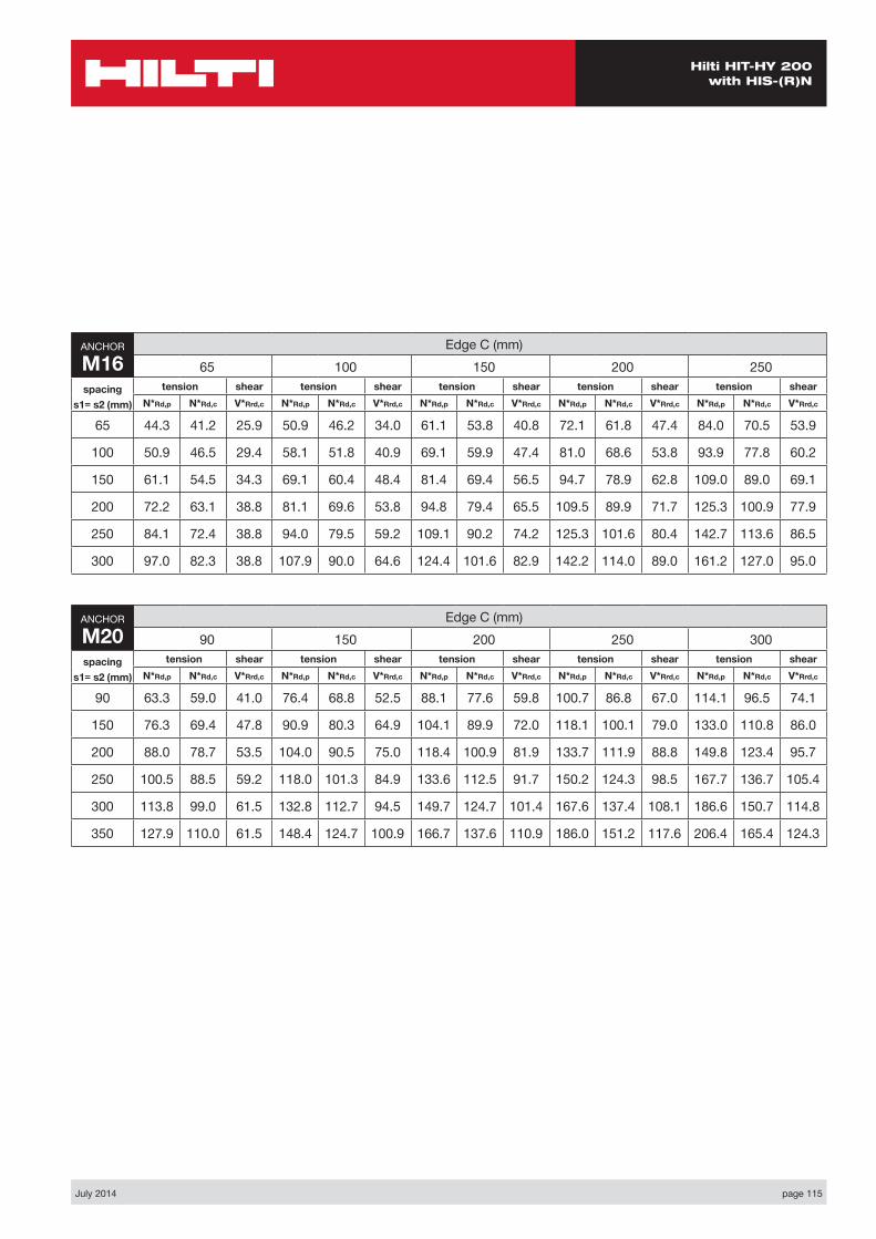
July 2014 page 115
Hilti HIT-HY 200 with HIS-(R)N
ANCHOR
M20Edge C (mm)
90 150 200 250 300spacing
s1= s2 (mm)
tension shear tension shear tension shear tension shear tension shearN*Rd,p N*Rd,c V*Rrd,c N*Rd,p N*Rd,c V*Rrd,c N*Rd,p N*Rd,c V*Rrd,c N*Rd,p N*Rd,c V*Rrd,c N*Rd,p N*Rd,c V*Rrd,c
90 63.3 59.0 41.0 76.4 68.8 52.5 88.1 77.6 59.8 100.7 86.8 67.0 114.1 96.5 74.1
150 76.3 69.4 47.8 90.9 80.3 64.9 104.1 89.9 72.0 118.1 100.1 79.0 133.0 110.8 86.0
200 88.0 78.7 53.5 104.0 90.5 75.0 118.4 100.9 81.9 133.7 111.9 88.8 149.8 123.4 95.7
250 100.5 88.5 59.2 118.0 101.3 84.9 133.6 112.5 91.7 150.2 124.3 98.5 167.7 136.7 105.4
300 113.8 99.0 61.5 132.8 112.7 94.5 149.7 124.7 101.4 167.6 137.4 108.1 186.6 150.7 114.8
350 127.9 110.0 61.5 148.4 124.7 100.9 166.7 137.6 110.9 186.0 151.2 117.6 206.4 165.4 124.3
ANCHOR
M16Edge C (mm)
65 100 150 200 250spacing
s1= s2 (mm)
tension shear tension shear tension shear tension shear tension shearN*Rd,p N*Rd,c V*Rrd,c N*Rd,p N*Rd,c V*Rrd,c N*Rd,p N*Rd,c V*Rrd,c N*Rd,p N*Rd,c V*Rrd,c N*Rd,p N*Rd,c V*Rrd,c
65 44.3 41.2 25.9 50.9 46.2 34.0 61.1 53.8 40.8 72.1 61.8 47.4 84.0 70.5 53.9
100 50.9 46.5 29.4 58.1 51.8 40.9 69.1 59.9 47.4 81.0 68.6 53.8 93.9 77.8 60.2
150 61.1 54.5 34.3 69.1 60.4 48.4 81.4 69.4 56.5 94.7 78.9 62.8 109.0 89.0 69.1
200 72.2 63.1 38.8 81.1 69.6 53.8 94.8 79.4 65.5 109.5 89.9 71.7 125.3 100.9 77.9
250 84.1 72.4 38.8 94.0 79.5 59.2 109.1 90.2 74.2 125.3 101.6 80.4 142.7 113.6 86.5
300 97.0 82.3 38.8 107.9 90.0 64.6 124.4 101.6 82.9 142.2 114.0 89.0 161.2 127.0 95.0
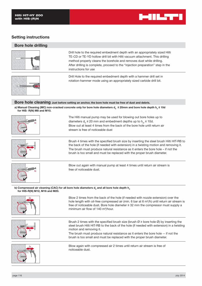
page 116 July 2014
Hilti HIT-HY 200 with HIS-(R)N
Setting instructions
Bore hole drillingDrill hole to the required embedment depth with an appropriately sized HiltiTE-CD or TE-YD hollow drill bit with Hilti vacuum attachment. This drillingmethod properly cleans the borehole and removes dust while drilling.After drilling is complete, proceed to the “injection preparation” step in theinstructions for use
Drill Hole to the required embedment depth with a hammer drill set inrotation-hammer mode using an appropriately sized carbide drill bit.
Bore hole cleaning Just before setting an anchor, the bore hole must be free of dust and debris.a) Manual Cleaning (MC) non-cracked concrete only for bore hole diameters d0 ≤ 20mm and bore hole depth h0 ≤ 10d
for HIS- R(N) M8 and M10.
The Hilti manual pump may be used for blowing out bore holes up todiameters d0 ≤ 20 mm and embedment depths up to hef ≤ 10d.Blow out at least 4 times from the back of the bore hole until return airstream is free of noticeable dust
Brush 4 times with the specified brush size by inserting the steel brush Hilti HIT-RB to the back of the hole (if needed with extension) in a twisting motion and removing it.The brush must produce natural resistance as it enters the bore hole – if not the brush is too small and must be replaced with the proper brush diameter.
Blow out again with manual pump at least 4 times until return air stream isfree of noticeable dust.
b) Compressed air cleaning (CAC) for all bore hole diameters d0 and all bore hole depth h0 for HIS-R(N) M12, M16 and M20.
Blow 2 times from the back of the hole (if needed with nozzle extension) over the hole length with oil-free compressed air (min. 6 bar at 6 m³/h) until return air stream is free of noticeable dust. Bore hole diameter ≥ 32 mm the compressor must supply a minimum air flow of 140 m³/hour.
Brush 2 times with the specified brush size (brush Ø ≥ bore hole Ø) by inserting the steel brush Hilti HIT-RB to the back of the hole (if needed with extension) in a twisting motion and removing it.The brush must produce natural resistance as it enters the bore hole -- if not the brush is too small and must be replaced with the proper brush diameter.
Blow again with compressed air 2 times until return air stream is free of noticeable dust.
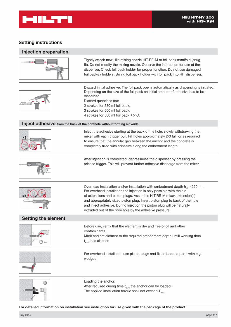
July 2014 page 117
Hilti HIT-HY 200 with HIS-(R)N
Setting instructions
Injection preparationTightly attach new Hilti mixing nozzle HIT-RE-M to foil pack manifold (snugfit). Do not modify the mixing nozzle. Observe the instruction for use of thedispenser. Check foil pack holder for proper function. Do not use damagedfoil packs / holders. Swing foil pack holder with foil pack into HIT dispenser.
Discard initial adhesive. The foil pack opens automatically as dispensing is initiated. Depending on the size of the foil pack an initial amount of adhesive has to be discarded.Discard quantities are:2 strokes for 330 ml foil pack,3 strokes for 500 ml foil pack,4 strokes for 500 ml foil pack ≤ 5°C.
Inject adhesive from the back of the borehole without forming air voids
Inject the adhesive starting at the back of the hole, slowly withdrawing themixer with each trigger pull. Fill holes approximately 2/3 full, or as requiredto ensure that the annular gap between the anchor and the concrete iscompletely filled with adhesive along the embedment length.
After injection is completed, depressurise the dispenser by pressing therelease trigger. This will prevent further adhesive discharge from the mixer.
Overhead installation and/or installation with embedment depth hef > 250mm. For overhead installation the injection is only possible with the aidof extensions and piston plugs. Assemble HIT-RE-M mixer, extension(s)and appropriately sized piston plug. Insert piston plug to back of the holeand inject adhesive. During injection the piston plug will be naturallyextruded out of the bore hole by the adhesive pressure.
Setting the elementBefore use, verify that the element is dry and free of oil and othercontaminants.Mark and set element to the required embedment depth untill working timetwork has elapsed
For overhead installation use piston plugs and fix embedded parts with e.g.wedges
Loading the anchor:After required curing time tcure the anchor can be loaded.The applied installation torque shall not exceed Tmax.
For detailed information on installation see instruction for use given with the package of the product.
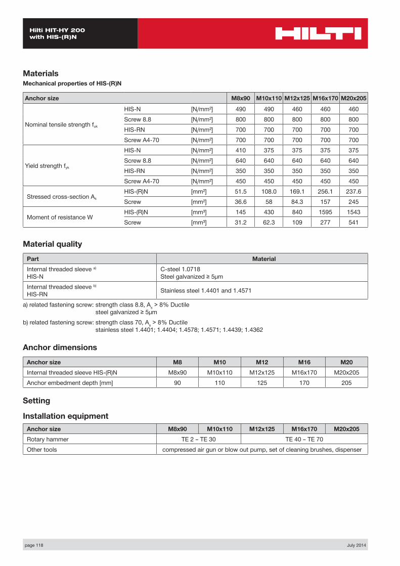
page 118 July 2014
Hilti HIT-HY 200 with HIS-(R)N
MaterialsMechanical properties of HIS-(R)N
Anchor size M8x90 M10x110 M12x125 M16x170 M20x205
Nominal tensile strength fuk
HIS-N [N/mm²] 490 490 460 460 460Screw 8.8 [N/mm²] 800 800 800 800 800HIS-RN [N/mm²] 700 700 700 700 700Screw A4-70 [N/mm²] 700 700 700 700 700
Yield strength fyk
HIS-N [N/mm²] 410 375 375 375 375Screw 8.8 [N/mm²] 640 640 640 640 640HIS-RN [N/mm²] 350 350 350 350 350Screw A4-70 [N/mm²] 450 450 450 450 450
Stressed cross-section AsHIS-(R)N [mm²] 51.5 108.0 169.1 256.1 237.6Screw [mm²] 36.6 58 84.3 157 245
Moment of resistance WHIS-(R)N [mm³] 145 430 840 1595 1543Screw [mm³] 31.2 62.3 109 277 541
Material quality
Part MaterialInternal threaded sleeve a) HIS-N
C-steel 1.0718 Steel galvanized ≥ 5μm
Internal threaded sleeve b) HIS-RN Stainless steel 1.4401 and 1.4571
a) related fastening screw: strength class 8.8, As > 8% Ductile steel galvanized ≥ 5μm
b) related fastening screw: strength class 70, As > 8% Ductile stainless steel 1.4401; 1.4404; 1.4578; 1.4571; 1.4439; 1.4362
Anchor dimensions
Anchor size M8 M10 M12 M16 M20Internal threaded sleeve HIS-(R)N M8x90 M10x110 M12x125 M16x170 M20x205Anchor embedment depth [mm] 90 110 125 170 205
Setting
Installation equipmentAnchor size M8x90 M10x110 M12x125 M16x170 M20x205Rotary hammer TE 2 – TE 30 TE 40 – TE 70Other tools compressed air gun or blow out pump, set of cleaning brushes, dispenser
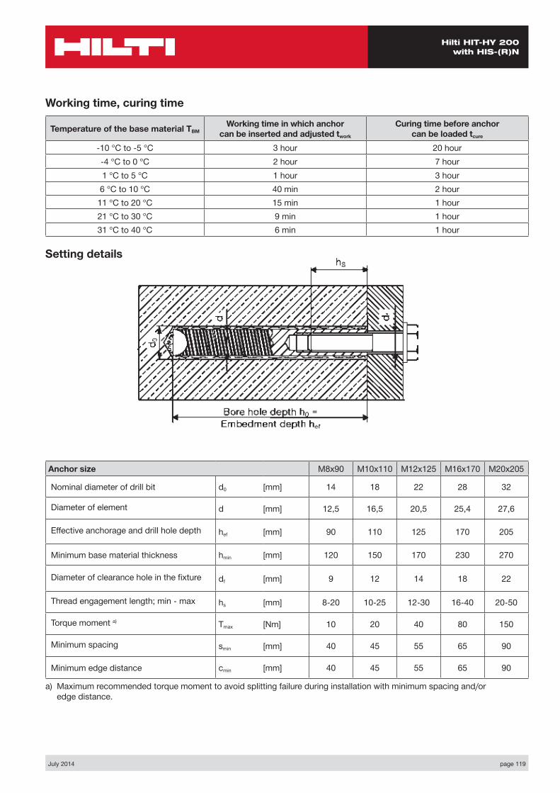
July 2014 page 119
Hilti HIT-HY 200 with HIS-(R)N
Setting details
Working time, curing time
Temperature of the base material TBMWorking time in which anchor
can be inserted and adjusted twork
Curing time before anchor can be loaded tcure
-10 °C to -5 °C 3 hour 20 hour-4 °C to 0 °C 2 hour 7 hour1 °C to 5 °C 1 hour 3 hour6 °C to 10 °C 40 min 2 hour
11 °C to 20 °C 15 min 1 hour21 °C to 30 °C 9 min 1 hour31 °C to 40 °C 6 min 1 hour
Anchor size M8x90 M10x110 M12x125 M16x170 M20x205
Nominal diameter of drill bit d0 [mm] 14 18 22 28 32
Diameter of element d [mm] 12,5 16,5 20,5 25,4 27,6
Effective anchorage and drill hole depth hef [mm] 90 110 125 170 205
Minimum base material thickness hmin [mm] 120 150 170 230 270
Diameter of clearance hole in the fixture df [mm] 9 12 14 18 22
Thread engagement length; min - max hs [mm] 8-20 10-25 12-30 16-40 20-50
Torque moment a) Tmax [Nm] 10 20 40 80 150
Minimum spacing smin [mm] 40 45 55 65 90
Minimum edge distance cmin [mm] 40 45 55 65 90
a) Maximum recommended torque moment to avoid splitting failure during installation with minimum spacing and/or edge distance.
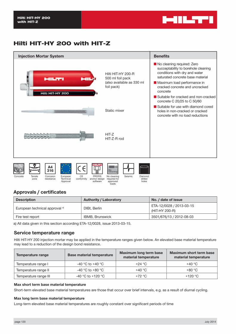
page 120 July 2014
Hilti HIT-HY 200 with HIT-Z
Hilti HIT-HY 200 with HIT-Z
Injection Mortar System Benefits
■ No cleaning required: Zero succeptability to borehole cleaning conditions with dry and water saturated concrete base material
■ Maximum load performance in cracked concrete and uncracked concrete
■ Suitable for cracked and non-cracked concrete C 20/25 to C 50/60
■ Suitable for use with diamond cored holes in non-cracked or cracked concrete with no load reductions
Approvals / certificatesDescription Authority / Laboratory No. / date of issue
European technical approval a) DIBt, Berlin ETA-12/0028 / 2013-03-15(HIT-HY 200-R)
Fire test report IBMB, Brunswick 3501/676/13 / 2012-08-03
a) All data given in this section according ETA-12/0028, issue 2013-03-15.
Service temperature rangeHilti HIT-HY 200 injection mortar may be applied in the temperature ranges given below. An elevated base material temperature may lead to a reduction of the design bond resistance.
Temperature range Base material temperature Maximum long term base material temperature
Maximum short term base material temperature
Temperature range I -40 °C to +40 °C +24 °C +40 °CTemperature range II -40 °C to +80 °C +40 °C +80 °CTemperature range III -40 °C to +120 °C +72 °C +120 °C
Max short term base material temperatureShort-term elevated base material temperatures are those that occur over brief intervals, e.g. as a result of diurnal cycling.
Max long term base material temperatureLong-term elevated base material temperatures are roughly constant over significant periods of time
Hilti HIT-HY 200-R500 ml foil pack(also available as 330 ml foil pack)
Static mixer
HIT-ZHIT-Z-R rod
CE conformity
European Technical Approval
Concrete
A4 316
Corrosion resistance
Tensile zone
PROFIS anchor design
software
No cleaningrequired forapproved
loads
Seismic Diamond drilled holes

July 2014 page 121
Hilti HIT-HY 200 with HIT-Z
Design process for typical anchor layoutsThe design values in the tables are obtained from Profis V2.4.3 in compliance with the design method according to EOTA TR 029. Design resistance according to data given in ETA-12/2008 issue 2013-03-15.■ Influence of concrete strength ■ Influence of edge distance ■ Influence of spacing
The design method is based on the following simplification:■ No different loads are acting on individual anchors (no eccentricity)
The values are valid for the anchor configuration.
For more complex fastening applications please use the anchor design software PROFIS Anchor.
STEP 1: TENSION LOADING
The design tensile resistance NRd is the lower of:
■ Combined pull-out and concrete cone resistance NRd,p = fB,p • N*Rd,p
N*Rd,p is obtained from the relevant design tables
fB,p influence of concrete strength on combined pull-out and concrete cone resistance
Concrete Strengths f’c,cyl (MPa) 20 25 32 40 50fB,p 1.00 1.00 1.00 1.00 1.00
■ Concrete cone or concrete splitting resistance NRd,c = fB • N*Rd,c
N*Rd,c is obtained from the relevant design tables
fB influence of concrete strength on concrete cone resistance
Concrete Strengths f’c,cyl (MPa) 20 25 32 40 50fB 0.79 0.87 1.00 1.11 1.22
The definition of dry concrete, as per Hilti is: concrete not in contact with water before/during installation and curing.
■ Design steel resistance (tension) NRd,s
Anchor size M8 M10 M12 M16 M20NRd,s HIT-Z / HIT-Z-R [kN] 16.0 25.3 36.7 64.0 97.3
NRd = min { NRd,p, NRd,c, NRd,s } CHECK NRd ≥ NSd

page 122 July 2014
Hilti HIT-HY 200 with HIT-Z
STEP 2: SHEAR LOADING
The design shear resistance VRd is the lower of:
■ Design Concrete Edge Resistance VRd,c = fB • V*Rd,c • ψre,V
V*Rd,c is obtained from the relevant design table
The factor ψre,V takes account of the effect of the type of reinforcement used in cracked concrete.ψre,V = 1.0 anchorage in non-cracked concreteψre,V = 1.0 anchorage in cracked concrete without edge reinforcementψre,V = 1.2 anchorage in cracked concrete with straight edge reinforcement (≥ ∅12 mm) ψre,V = 1.4 anchorage in cracked concrete with edge reinforcement and closely spaced stirrups (a ≤ 100 mm)
fB influence of concrete strength
Concrete Strengths f’c,cyl (MPa) 20 25 32 40 50fB 0.79 0.87 1.00 1.11 1.22
Shear load acting parallel to edge:These tables are for a single free edge only2 anchors:For shear loads acting parallel to this edge, the concrete resistance V*Rd,c can be multiplied by the factor = 2.54 anchors:For shear loads acting parallel to the edge - the anchor row closest to the edge is checked to resist half the total design load. To obtain the concrete resistance use the corresponding 2 anchor configuration V*Rd,c and multiply by the factor = 2.5
■ Design steel resistance (shear): VRd,s
Anchor size M8 M10 M12 M16 M20VRd,s HIT-Z [kN] 9.6 15.2 21.6 38.4 58.4
HIT-Z-R [kN] 11.2 18.4 26.4 45.6 70.4
VRd = min { VRd,c, VRd,s } CHECK VRd ≥ VSd
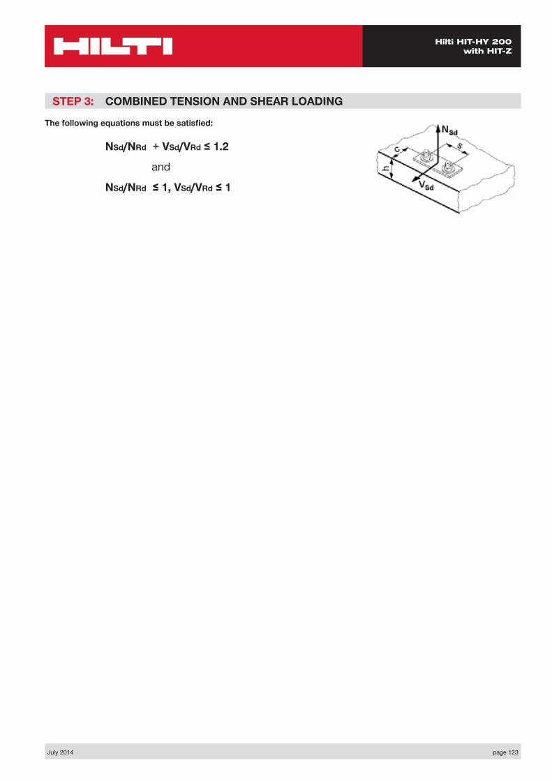
July 2014 page 123
Hilti HIT-HY 200 with HIT-Z
STEP 3: COMBINED TENSION AND SHEAR LOADING
The following equations must be satisfied:
NSd/NRd + VSd/VRd ≤ 1.2
and
NSd/NRd ≤ 1, VSd/VRd ≤ 1
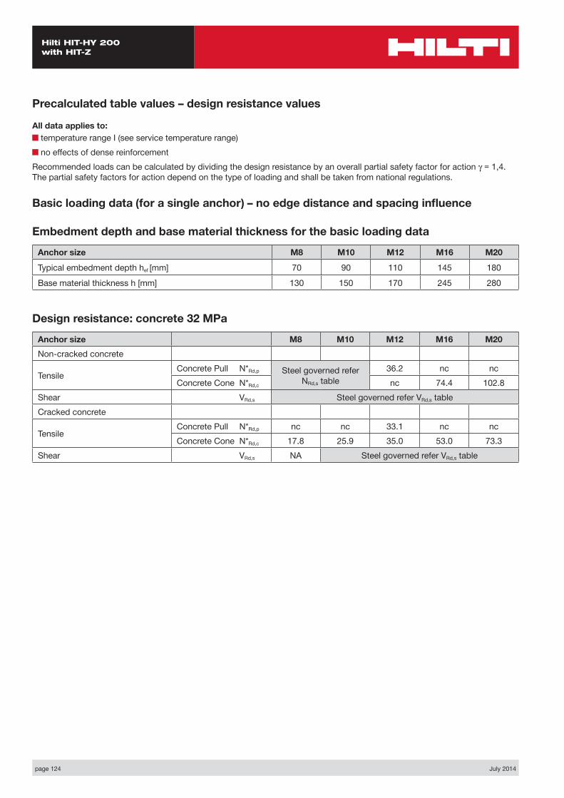
page 124 July 2014
Hilti HIT-HY 200 with HIT-Z
Precalculated table values – design resistance values
All data applies to:■ temperature range I (see service temperature range)■ no effects of dense reinforcementRecommended loads can be calculated by dividing the design resistance by an overall partial safety factor for action γ = 1,4. The partial safety factors for action depend on the type of loading and shall be taken from national regulations.
Basic loading data (for a single anchor) – no edge distance and spacing influence
Embedment depth and base material thickness for the basic loading data
Anchor size M8 M10 M12 M16 M20
Typical embedment depth hef [mm] 70 90 110 145 180
Base material thickness h [mm] 130 150 170 245 280
Design resistance: concrete 32 MPa
Anchor size M8 M10 M12 M16 M20Non-cracked concrete
Tensile Concrete Pull N*Rd,p Steel governed refer
NRd,s table36.2 nc nc
Concrete Cone N*Rd,c nc 74.4 102.8Shear VRd,s Steel governed refer VRd,s tableCracked concrete
Tensile Concrete Pull N*Rd,p nc nc 33.1 nc ncConcrete Cone N*Rd,c 17.8 25.9 35.0 53.0 73.3
Shear VRd,s NA Steel governed refer VRd,s table
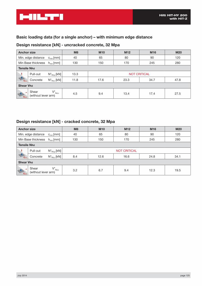
July 2014 page 125
Hilti HIT-HY 200 with HIT-Z
Basic loading data (for a single anchor) – with minimum edge distance
Design resistance [kN] - uncracked concrete, 32 Mpa
Anchor size M8 M10 M12 M16 M20Min. edge distance cmin [mm] 40 65 80 90 120Min Base thickness hmin [mm] 130 150 170 245 280
Tensile NRd
Pull-out N*Rd,p [kN] 13.3 NOT CRITICAL
Concrete N*Rd,c [kN] 11.8 17.6 23.3 34.7 47.8
Shear VRd
Shear V*Rd,c (without lever arm) 4.5 9.4 13.4 17.4 27.5
Design resistance [kN] - cracked concrete, 32 Mpa
Anchor size M8 M10 M12 M16 M20Min. edge distance cmin [mm] 40 65 80 90 120Min Base thickness hmin [mm] 130 150 170 245 280
Tensile NRd
Pull-out N*Rd,p [kN] NOT CRITICAL
Concrete N*Rd,c [kN] 8.4 12.6 16.6 24.8 34.1
Shear VRd
Shear V*Rd,c (without lever arm) 3.2 6.7 9.4 12.3 19.5

page 126 July 2014
Hilti HIT-HY 200 with HIT-Z
Nsd
Vsd
S1
C
h
Two anchors Table 1: One edge influence – non cracked concrete
Design Data: fc,cyl=32 MPa
Anchor size M8 M10 M12 M16 M20Typical embedment depth hef [mm] 70 90 110 145 180
Min Slab depth 130 150 170 245 280
ANCHOR
M8Edge C (mm)
40 80 100 150 170spacings1 (mm)
tension shear tension shear tension shear tension shear tension shearN*Rd,p N*Rd,c V*Rrd,c N*Rd,p N*Rd,c V*Rrd,c N*Rd,p N*Rd,c V*Rrd,c N*Rd,p N*Rd,c V*Rrd,c N*Rd,p N*Rd,c V*Rrd,c
40 - - - 17.0 13.4 19.1 16.4 25.5 24.8 22.5 25.5 27.3 24.9
80 14.5 7.6 18.8 15.3 21.1 18.4 30.8 27.4 24.3 30.8 30.1 26.7
100 15.2 8.4 19.6 16.3 22.1 19.3 33.5 28.7 25.2 33.5 31.5 27.6
120 15.9 9.2 20.5 17.3 23.0 20.3 36.2 29.9 26.1 36.2 32.9 28.5
150 16.9 9.2 21.8 18.7 24.5 21.7 40.2 31.9 27.5 40.2 35.0 29.8
200 18.6 9.2 24.0 21.1 27.0 24.1 40.2 35.1 29.8 40.2 38.6 32.1
ANCHOR
M10Edge C (mm)
80 110 150 200 250spacings1 (mm)
tension shear tension shear tension shear tension shear tension shearN*Rd,p N*Rd,c V*Rrd,c N*Rd,p N*Rd,c V*Rrd,c N*Rd,p N*Rd,c V*Rrd,c N*Rd,p N*Rd,c V*Rrd,c N*Rd,p N*Rd,c V*Rrd,c
80 - - - 24.8 22.5 29.0 27.8 34.8 34.3 43.6 41.0 40.7
100 - - - 25.6 23.6 30.0 28.8 35.9 35.3 46.9 42.3 41.7
150 24.4 20.2 27.7 26.4 32.5 31.4 38.9 37.8 55.3 45.8 44.2
200 26.2 22.8 29.8 29.1 34.9 34.1 41.8 40.3 60.3 49.2 46.6
250 28.0 24.9 31.9 31.8 37.3 36.7 44.7 42.8 60.3 52.7 49.1
300 29.9 24.9 34.0 34.6 39.8 39.3 47.6 45.4 60.3 56.1 51.5
ANCHOR
M12Edge C (mm)
100 150 200 250 300spacings1 (mm)
tension shear tension shear tension shear tension shear tension shearN*Rd,p N*Rd,c V*Rrd,c N*Rd,p N*Rd,c V*Rrd,c N*Rd,p N*Rd,c V*Rrd,c N*Rd,p N*Rd,c V*Rrd,c N*Rd,p N*Rd,c V*Rrd,c
150 - - - 35.8 35.4 41.6 42.3 47.7 49.2 66.4 54.2 56.1
180 31.6 28.6 37.1 37.2 43.1 44.0 49.4 50.9 72.4 56.1 57.7
200 32.3 29.8 38.0 38.4 44.1 45.2 50.5 52.0 72.4 57.4 58.8
250 34.2 32.8 40.1 41.3 46.5 48.0 53.4 54.7 72.4 60.7 61.5
300 36.0 35.7 42.3 44.3 49.0 50.8 56.2 57.4 72.4 63.9 64.1
350 37.8 35.7 44.4 47.2 51.5 53.6 59.1 60.2 72.4 67.1 66.8
NO
T C
RITI
CAL
NO
T C
RITI
CAL
NO
T C
RITI
CAL
NO
T C
RITI
CAL
NO
T C
RITI
CAL
NO
T C
RITI
CAL
NO
T C
RITI
CAL
NO
T C
RITI
CAL
NO
T C
RITI
CAL
NO
T C
RITI
CAL
NO
T C
RITI
CAL

July 2014 page 127
Hilti HIT-HY 200 with HIT-Z
ANCHOR
M16Edge C (mm)
120 150 200 250 300spacings1 (mm)
tension shear tension shear tension shear tension shear tension shearN*Rd,p N*Rd,c V*Rrd,c N*Rd,p N*Rd,c V*Rrd,c N*Rd,p N*Rd,c V*Rrd,c N*Rd,p N*Rd,c V*Rrd,c N*Rd,p N*Rd,c V*Rrd,c
150 - - - 48.7 44.8 55.5 55.3 62.6 63.9 70.2 72.4
180 46.2 37.7 50.2 47.0 57.2 57.5 64.6 66.0 72.3 74.5
210 47.6 39.8 51.7 49.2 58.9 59.7 66.5 68.1 74.5 76.5
250 49.5 42.6 53.7 52.2 61.2 62.7 69.1 71.0 77.4 79.3
300 51.8 46.1 56.3 55.9 64.1 66.3 72.3 74.5 81.0 82.7
350 54.1 49.6 58.8 59.7 66.9 70.0 75.6 78.1 84.7 86.2
ANCHOR
M20Edge C (mm)
180 200 250 300 350spacings1 (mm)
tension shear tension shear tension shear tension shear tension shearN*Rd,p N*Rd,c V*Rrd,c N*Rd,p N*Rd,c V*Rrd,c N*Rd,p N*Rd,c V*Rrd,c N*Rd,p N*Rd,c V*Rrd,c N*Rd,p N*Rd,c V*Rrd,c
150 - - - 64.1 63.7 70.6 73.2 77.4 82.6 84.5 91.9
180 63.0 61.4 65.6 66.3 72.3 75.6 79.3 84.9 86.5 94.2
210 64.5 64.0 67.2 68.8 74.0 78.0 81.1 87.3 88.5 96.5
250 66.5 67.4 69.2 72.2 76.2 81.3 83.6 90.4 91.2 99.6
300 68.9 71.7 71.7 76.5 79.0 85.4 86.6 94.4 94.6 103.4
350 71.3 75.9 74.3 80.7 81.8 89.4 89.7 98.3 97.9 107.2
NO
T C
RITI
CAL
NO
T C
RITI
CAL
NO
T C
RITI
CAL
NO
T C
RITI
CAL
NO
T C
RITI
CAL
NO
T C
RITI
CAL
NO
T C
RITI
CAL
NO
T C
RITI
CAL
NO
T C
RITI
CAL
NO
T C
RITI
CAL

page 128 July 2014
Hilti HIT-HY 200 with HIT-Z
Four anchors Table 2: One edge influence – non cracked concrete
Design Data: fc,cyl=32 MPa
Anchor size M8 M10 M12 M16 M20Typical embedment depth hef [mm] 70 90 110 145 180
Min Slab depth 130 150 170 245 280
Nsd
Vsd
S2
S1
C
h
ANCHOR
M8Edge C (mm)
40 80 100 150 170spacings1 = s2
tension shear tension shear tension shear tension shear tension shearN*Rd,p N*Rd,c V*Rrd,c N*Rd,p N*Rd,c V*Rrd,c N*Rd,p N*Rd,c V*Rrd,c N*Rd,p N*Rd,c V*Rrd,c N*Rd,p N*Rd,c V*Rrd,c
40 - - - 19.7 13.4 21.9 16.4 32.3 27.9 22.5 32.3 31.0 28.4
80 19.9 7.6 24.7 15.3 27.2 18.4 47.3 34.1 24.3 47.3 37.7 30.2
100 22.3 8.4 27.4 16.3 30.1 19.3 55.9 37.5 25.2 55.9 41.3 31.1
120 24.8 9.2 30.2 17.3 33.1 20.3 65.1 41.0 26.1 65.1 45.1 32.0
150 28.7 9.2 34.7 18.7 37.9 21.7 80.4 46.6 27.5 80.4 51.1 33.3
200 35.9 9.2 42.9 21.1 46.7 24.1 80.4 56.7 29.8 80.4 61.9 35.5
ANCHOR
M10Edge C (mm)
80 110 150 200 250spacings1 = s2
tension shear tension shear tension shear tension shear tension shearN*Rd,p N*Rd,c V*Rrd,c N*Rd,p N*Rd,c V*Rrd,c N*Rd,p N*Rd,c V*Rrd,c N*Rd,p N*Rd,c V*Rrd,c N*Rd,p N*Rd,c V*Rrd,c
100 31.5 22.3 37.4 28.8 43.8 35.3 50.7 41.7 51.8 48.1
130 35.1 24.0 41.5 30.4 48.4 36.8 55.8 43.2 57.0 49.5
170 40.4 26.2 47.4 32.5 54.9 38.8 62.9 45.1 64.3 51.4
200 44.5 27.9 52.0 34.1 60.0 40.3 68.6 46.6 70.0 52.9
250 51.9 30.7 60.2 36.7 69.1 42.8 78.6 49.1 80.1 55.3
300 59.9 33.5 69.0 39.3 78.8 45.4 89.2 51.5 90.9 57.7
ANCHOR
M12Edge C (mm)
100 150 200 250 300spacings1 = s2
tension shear tension shear tension shear tension shear tension shearN*Rd,p N*Rd,c V*Rrd,c N*Rd,p N*Rd,c V*Rrd,c N*Rd,p N*Rd,c V*Rrd,c N*Rd,p N*Rd,c V*Rrd,c N*Rd,p N*Rd,c V*Rrd,c
100 - - - 40.5 32.5 46.3 39.5 52.4 46.5 58.8 53.4
150 - - - 46.8 35.4 53.1 42.3 59.7 49.2 66.8 56.1
200 47.0 29.8 53.4 38.4 60.3 45.2 67.6 52.0 75.3 58.8
250 53.5 32.8 60.5 41.3 68.0 48.0 75.9 54.7 84.3 61.5
300 60.4 35.7 68.1 44.3 76.2 50.8 84.7 57.4 93.8 64.1
350 67.7 35.7 76.0 47.2 84.8 53.6 94.0 60.2 103.7 66.8
NO
T C
RITI
CAL
NO
T C
RITI
CAL
NO
T C
RITI
CAL
NO
T C
RITI
CAL
NO
T C
RITI
CAL
NO
T C
RITI
CAL
NO
T C
RITI
CAL
NO
T C
RITI
CAL
NO
T C
RITI
CAL
NO
T C
RITI
CAL
NO
T C
RITI
CAL
NO
T C
RITI
CAL
NO
T C
RITI
CAL

July 2014 page 129
Hilti HIT-HY 200 with HIT-Z
ANCHOR
M16Edge C (mm)
120 150 200 250 300spacings1 = s2
tension shear tension shear tension shear tension shear tension shearN*Rd,p N*Rd,c V*Rrd,c N*Rd,p N*Rd,c V*Rrd,c N*Rd,p N*Rd,c V*Rrd,c N*Rd,p N*Rd,c V*Rrd,c N*Rd,p N*Rd,c V*Rrd,c
120 - - - 57.3 42.5 64.3 53.1 71.7 61.7 79.5 70.3
170 60.5 37.0 64.8 46.2 72.4 56.8 80.4 65.3 88.8 73.8
200 65.0 39.1 69.6 48.5 77.5 59.0 85.8 67.4 94.6 75.9
250 72.9 42.6 77.8 52.2 86.3 62.7 95.3 71.0 104.7 79.3
300 81.2 46.1 86.4 55.9 95.6 66.3 105.3 74.5 115.3 82.7
350 89.9 49.6 95.6 59.7 105.4 70.0 115.7 78.1 126.5 86.2
ANCHOR
M20Edge C (mm)
180 200 250 300 350spacings1 = s2
tension shear tension shear tension shear tension shear tension shearN*Rd,p N*Rd,c V*Rrd,c N*Rd,p N*Rd,c V*Rrd,c N*Rd,p N*Rd,c V*Rrd,c N*Rd,p N*Rd,c V*Rrd,c N*Rd,p N*Rd,c V*Rrd,c
150 - - - 76.8 63.7 83.8 73.2 91.0 82.6 98.5 91.9
200 - - - 84.3 68.0 91.7 77.2 99.3 86.5 107.3 95.7
250 - - - 92.1 72.2 99.9 81.3 108.0 90.4 116.4 99.6
300 92.3 60.9 100.2 76.5 108.4 85.4 117.0 94.4 125.9 103.4
350 100.3 64.9 108.7 80.7 117.4 89.4 126.4 98.3 135.8 107.2
400 108.6 69.0 117.4 85.0 126.6 93.5 136.1 102.2 146.0 111.0
NO
T C
RITI
CAL
NO
T C
RITI
CAL
NO
T C
RITI
CAL
NO
T C
RITI
CAL
NO
T C
RITI
CAL
NO
T C
RITI
CAL
NO
T C
RITI
CAL
NO
T C
RITI
CAL
NO
T C
RITI
CAL
NO
T C
RITI
CAL

page 130 July 2014
Hilti HIT-HY 200 with HIT-Z
Nsd
Vsd
S1
C
h
Two anchors Table 1: One edge influence – cracked concrete
Design Data: fc,cyl=32 MPa – Cracked Concrete
Anchor size M8 M10 M12 M16 M20Typical embedment depth hef [mm] 70 90 110 145 180
Min Slab depth 130 150 170 245 280
ANCHOR
M8Edge C (mm)
50 80 100 150 200spacings1 (mm)
tension shear tension shear tension shear tension shear tension shearN*Rd,p N*Rd,c V*Rrd,c N*Rd,p N*Rd,c V*Rrd,c N*Rd,p N*Rd,c V*Rrd,c N*Rd,p N*Rd,c V*Rrd,c N*Rd,p N*Rd,c V*Rrd,c
50 10.3 5.8 12.4 9.8 14.0 12.0 18.2 16.2 24.6 20.3 20.4
100 11.6 7.3 14.0 11.5 15.7 13.7 20.4 17.9 30.7 22.9 22.0
150 12.9 8.7 15.6 13.2 17.5 15.4 22.7 19.5 36.9 25.4 23.6
200 14.2 8.7 17.1 14.9 19.2 17.1 25.0 21.1 36.9 28.0 25.2
250 15.5 8.7 18.7 16.3 21.0 18.8 27.3 22.7 36.9 30.6 26.7
300 16.8 8.7 20.3 16.3 22.7 20.5 29.6 24.4 36.9 33.1 28.3
ANCHOR
M10Edge C (mm)
70 90 110 150 200spacings1 (mm)
tension shear tension shear tension shear tension shear tension shearN*Rd,p N*Rd,c V*Rrd,c N*Rd,p N*Rd,c V*Rrd,c N*Rd,p N*Rd,c V*Rrd,c N*Rd,p N*Rd,c V*Rrd,c N*Rd,p N*Rd,c V*Rrd,c
70 14.6 9.9 16.0 13.0 17.4 15.6 20.4 19.3 24.4 23.9
100 15.4 10.9 16.8 14.1 18.3 16.7 21.4 20.4 25.6 25.0
150 16.6 12.7 18.2 16.0 19.8 18.7 23.1 22.3 27.7 26.8
200 17.9 14.4 19.5 17.9 21.2 20.6 24.9 24.1 29.8 28.6
250 19.1 14.8 20.9 19.8 22.7 22.6 26.6 26.0 31.9 30.4
300 20.4 14.8 22.2 20.6 24.2 24.5 28.3 27.8 33.9 32.1
ANCHOR
M12Edge C (mm)
80 100 150 200 250spacings1 (mm)
tension shear tension shear tension shear tension shear tension shearN*Rd,p N*Rd,c V*Rrd,c N*Rd,p N*Rd,c V*Rrd,c N*Rd,p N*Rd,c V*Rrd,c N*Rd,p N*Rd,c V*Rrd,c N*Rd,p N*Rd,c V*Rrd,c
80 - - - 19.9 16.0 23.4 22.2 27.1 27.2 31.1 32.2
100 - - - 20.4 16.9 24.0 23.0 27.9 28.0 31.9 32.9
150 20.3 15.4 21.7 19.0 25.5 25.1 29.6 30.0 34.0 34.9
200 21.5 17.4 23.0 21.1 27.1 27.2 31.4 32.0 36.0 36.8
250 22.7 18.9 24.3 23.2 28.6 29.3 33.2 34.0 38.1 38.8
300 23.9 18.9 25.7 25.3 30.1 31.3 35.0 36.0 40.1 40.7
Tensile zone
NO
T C
RITI
CAL
NO
T C
RITI
CAL
NO
T C
RITI
CAL
NO
T C
RITI
CAL
NO
T C
RITI
CAL
NO
T C
RITI
CAL
NO
T C
RITI
CAL
NO
T C
RITI
CAL
NO
T C
RITI
CAL
NO
T C
RITI
CAL
NO
T C
RITI
CAL
NO
T C
RITI
CAL
NO
T C
RITI
CAL
NO
T C
RITI
CAL

July 2014 page 131
Hilti HIT-HY 200 with HIT-Z
ANCHOR
M20Edge C (mm)
120 150 200 250 350spacings1 (mm)
tension shear tension shear tension shear tension shear tension shearN*Rd,p N*Rd,c V*Rrd,c N*Rd,p N*Rd,c V*Rrd,c N*Rd,p N*Rd,c V*Rrd,c N*Rd,p N*Rd,c V*Rrd,c N*Rd,p N*Rd,c V*Rrd,c
120 - - - 40.3 32.8 44.6 43.3 49.2 50.1 58.8 63.5
150 - - - 41.3 34.5 45.7 45.1 50.4 51.8 60.3 65.1
200 40.2 30.4 42.9 37.4 47.5 48.2 52.3 54.7 62.6 67.8
250 41.8 33.1 44.5 40.2 49.3 51.2 54.3 57.6 65.0 70.5
300 43.3 35.8 46.2 43.1 51.1 54.2 56.3 60.5 67.4 73.2
350 44.8 38.6 47.8 46.0 52.9 57.2 58.3 63.3 69.8 75.9
ANCHOR
M16Edge C (mm)
100 150 200 250 300spacings1 (mm)
tension shear tension shear tension shear tension shear tension shearN*Rd,p N*Rd,c V*Rrd,c N*Rd,p N*Rd,c V*Rrd,c N*Rd,p N*Rd,c V*Rrd,c N*Rd,p N*Rd,c V*Rrd,c N*Rd,p N*Rd,c V*Rrd,c
100 28.6 18.8 32.9 29.1 37.5 36.6 42.3 42.7 47.4 48.8
150 30.2 21.2 34.7 31.7 39.5 39.2 44.6 45.2 50.0 51.3
200 31.7 23.6 36.5 34.3 41.6 41.8 47.0 47.8 52.6 53.7
250 33.3 25.9 38.3 37.0 43.6 44.4 49.3 50.3 55.2 56.2
300 34.9 28.3 40.1 39.6 45.7 47.0 51.6 52.8 57.8 58.6
350 36.4 28.3 41.9 42.3 47.7 49.6 53.9 55.3 60.4 61.1
NO
T C
RITI
CAL
NO
T C
RITI
CAL
NO
T C
RITI
CAL
NO
T C
RITI
CAL
NO
T C
RITI
CAL
NO
T C
RITI
CAL
NO
T C
RITI
CAL
NO
T C
RITI
CAL
NO
T C
RITI
CAL
NO
T C
RITI
CAL

page 132 July 2014
Hilti HIT-HY 200 with HIT-Z
Four anchors Table 2: One edge influence – cracked concrete
Design Data: fc,cyl=32 MPa– Cracked Concrete
Anchor size M8 M10 M12 M16 M20Typical embedment depth hef [mm] 70 90 110 145 180
Min Slab depth 130 150 170 245 280
ANCHOR
M8Edge C (mm)
50 80 100 150 200spacing
s1=s2 (mm)
tension shear tension shear tension shear tension shear tension shearN*Rd,p N*Rd,c V*Rrd,c N*Rd,p N*Rd,c V*Rrd,c N*Rd,p N*Rd,c V*Rrd,c N*Rd,p N*Rd,c V*Rrd,c N*Rd,p N*Rd,c V*Rrd,c
50 12.6 5.8 14.9 9.8 16.5 12.0 21.0 16.2 32.8 23.3 20.4
100 16.8 7.3 19.5 11.5 21.5 13.7 26.7 17.9 51.2 29.5 22.0
150 21.5 8.7 24.8 13.2 27.0 15.4 33.2 19.5 73.7 36.4 23.6
200 26.8 8.7 30.6 14.9 33.3 17.1 40.4 21.1 73.7 44.1 25.2
250 32.7 8.7 37.1 16.3 40.1 18.8 48.3 22.7 73.7 52.5 26.7
300 39.2 8.7 44.2 16.3 47.6 20.5 56.9 24.4 73.7 61.7 28.3
ANCHOR
M10Edge C (mm)
60 80 100 150 200spacing
s1=s2 (mm)
tension shear tension shear tension shear tension shear tension shearN*Rd,p N*Rd,c V*Rrd,c N*Rd,p N*Rd,c V*Rrd,c N*Rd,p N*Rd,c V*Rrd,c N*Rd,p N*Rd,c V*Rrd,c N*Rd,p N*Rd,c V*Rrd,c
60 - - - 17.7 11.0 19.1 14.2 23.0 18.9 27.1 23.6
100 19.3 9.4 20.8 12.5 22.4 15.8 26.6 20.4 31.2 25.0
150 23.4 11.1 25.1 14.3 26.9 17.8 31.6 22.3 36.8 26.8
200 27.8 12.1 29.7 16.2 31.8 19.7 37.1 24.1 42.8 28.6
250 32.6 12.1 34.8 17.6 37.0 21.7 42.9 26.0 49.2 30.4
300 37.8 12.1 40.2 17.6 42.7 23.7 49.2 27.8 56.2 32.1
ANCHOR
M12Edge C (mm)
80 100 150 200 250spacing
s1=s2 (mm)
tension shear tension shear tension shear tension shear tension shearN*Rd,p N*Rd,c V*Rrd,c N*Rd,p N*Rd,c V*Rrd,c N*Rd,p N*Rd,c V*Rrd,c N*Rd,p N*Rd,c V*Rrd,c N*Rd,p N*Rd,c V*Rrd,c
80 - - - 23.5 16.0 27.2 22.2 31.1 27.2 35.3 32.2
100 - - - 25.1 16.9 28.9 23.0 33.0 28.0 37.3 32.9
150 27.5 15.4 29.1 19.0 33.3 25.1 37.8 30.0 42.6 34.9
200 31.7 17.4 33.5 21.1 38.1 27.2 43.0 32.0 48.2 36.8
250 36.2 18.9 38.1 23.2 43.1 29.3 48.5 34.0 54.1 38.8
300 41.0 18.9 43.1 25.3 48.5 31.3 54.3 36.0 60.4 40.7
Nsd
Vsd
S2
S1
C
h
Tensile zone
NO
T C
RITI
CAL
NO
T C
RITI
CAL
NO
T C
RITI
CAL
NO
T C
RITI
CAL
NO
T C
RITI
CAL
NO
T C
RITI
CAL
NO
T C
RITI
CAL
NO
T C
RITI
CAL
NO
T C
RITI
CAL
NO
T C
RITI
CAL
NO
T C
RITI
CAL
NO
T C
RITI
CAL
NO
T C
RITI
CAL
NO
T C
RITI
CAL
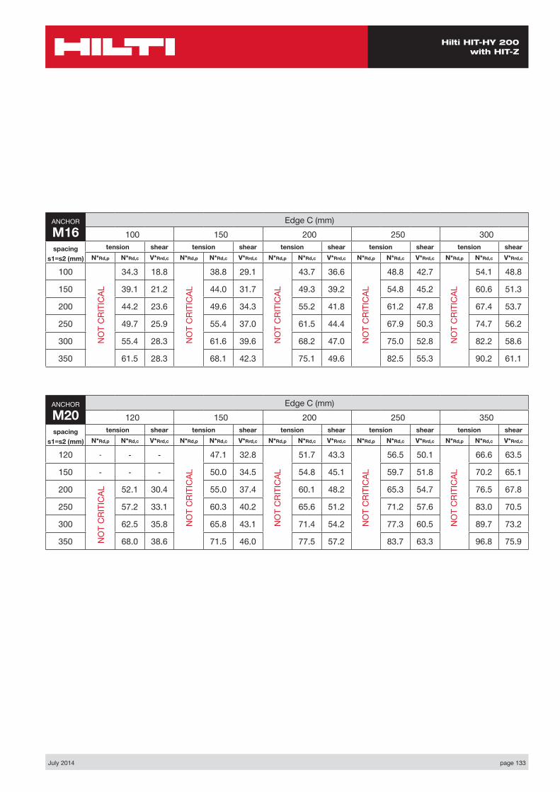
July 2014 page 133
Hilti HIT-HY 200 with HIT-Z
ANCHOR
M20Edge C (mm)
120 150 200 250 350spacing
s1=s2 (mm)
tension shear tension shear tension shear tension shear tension shearN*Rd,p N*Rd,c V*Rrd,c N*Rd,p N*Rd,c V*Rrd,c N*Rd,p N*Rd,c V*Rrd,c N*Rd,p N*Rd,c V*Rrd,c N*Rd,p N*Rd,c V*Rrd,c
120 - - - 47.1 32.8 51.7 43.3 56.5 50.1 66.6 63.5
150 - - - 50.0 34.5 54.8 45.1 59.7 51.8 70.2 65.1
200 52.1 30.4 55.0 37.4 60.1 48.2 65.3 54.7 76.5 67.8
250 57.2 33.1 60.3 40.2 65.6 51.2 71.2 57.6 83.0 70.5
300 62.5 35.8 65.8 43.1 71.4 54.2 77.3 60.5 89.7 73.2
350 68.0 38.6 71.5 46.0 77.5 57.2 83.7 63.3 96.8 75.9
ANCHOR
M16Edge C (mm)
100 150 200 250 300spacing
s1=s2 (mm)
tension shear tension shear tension shear tension shear tension shearN*Rd,p N*Rd,c V*Rrd,c N*Rd,p N*Rd,c V*Rrd,c N*Rd,p N*Rd,c V*Rrd,c N*Rd,p N*Rd,c V*Rrd,c N*Rd,p N*Rd,c V*Rrd,c
100 34.3 18.8 38.8 29.1 43.7 36.6 48.8 42.7 54.1 48.8
150 39.1 21.2 44.0 31.7 49.3 39.2 54.8 45.2 60.6 51.3
200 44.2 23.6 49.6 34.3 55.2 41.8 61.2 47.8 67.4 53.7
250 49.7 25.9 55.4 37.0 61.5 44.4 67.9 50.3 74.7 56.2
300 55.4 28.3 61.6 39.6 68.2 47.0 75.0 52.8 82.2 58.6
350 61.5 28.3 68.1 42.3 75.1 49.6 82.5 55.3 90.2 61.1
NO
T C
RITI
CAL
NO
T C
RITI
CAL
NO
T C
RITI
CAL
NO
T C
RITI
CAL
NO
T C
RITI
CAL
NO
T C
RITI
CAL
NO
T C
RITI
CAL
NO
T C
RITI
CAL
NO
T C
RITI
CAL
NO
T C
RITI
CAL
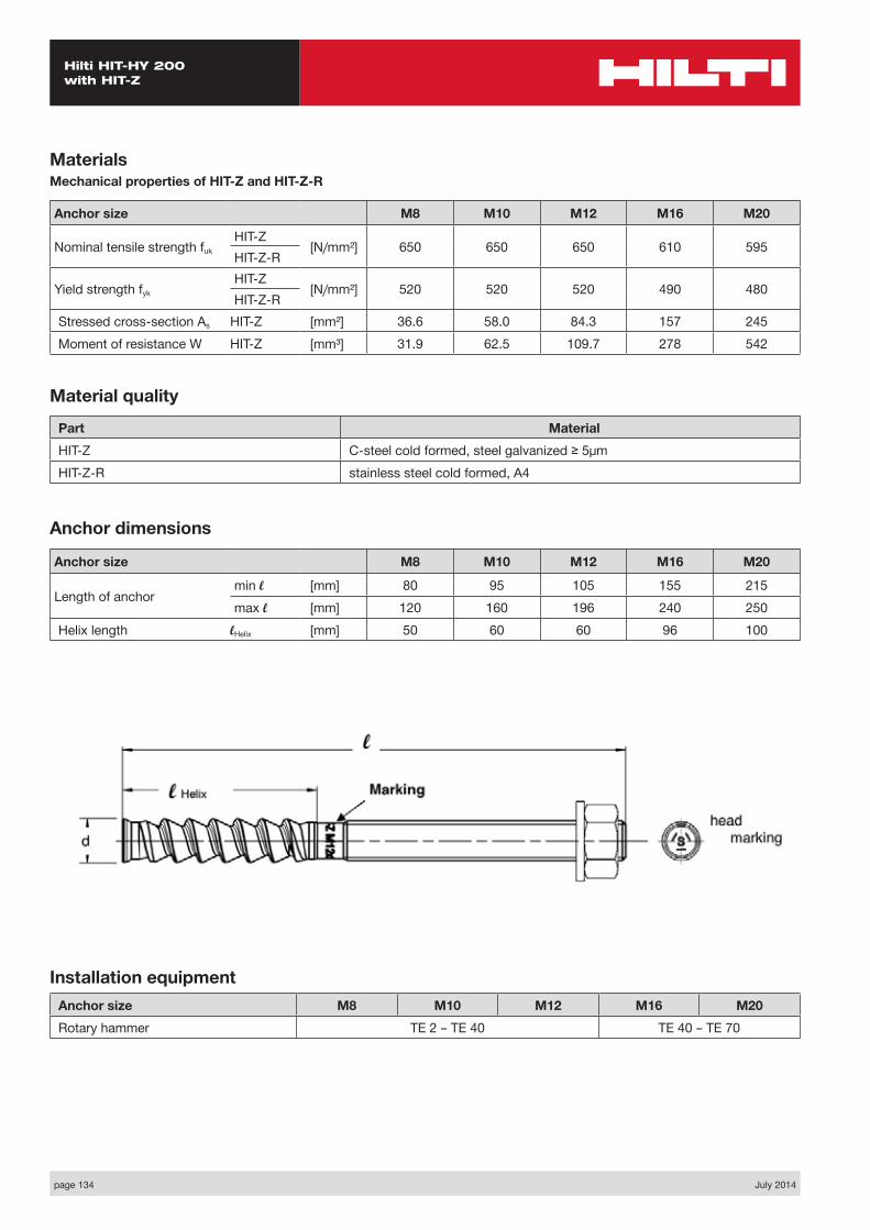
page 134 July 2014
Hilti HIT-HY 200 with HIT-Z
MaterialsMechanical properties of HIT-Z and HIT-Z-R
Anchor size M8 M10 M12 M16 M20
Nominal tensile strength fukHIT-Z
[N/mm²] 650 650 650 610 595HIT-Z-R
Yield strength fykHIT-Z
[N/mm²] 520 520 520 490 480HIT-Z-R
Stressed cross-section As HIT-Z [mm²] 36.6 58.0 84.3 157 245Moment of resistance W HIT-Z [mm³] 31.9 62.5 109.7 278 542
Material quality
Part MaterialHIT-Z C-steel cold formed, steel galvanized ≥ 5μmHIT-Z-R stainless steel cold formed, A4
Anchor dimensions
Anchor size M8 M10 M12 M16 M20
Length of anchormin l [mm] 80 95 105 155 215max l [mm] 120 160 196 240 250
Helix length lHelix [mm] 50 60 60 96 100
Installation equipmentAnchor size M8 M10 M12 M16 M20Rotary hammer TE 2 – TE 40 TE 40 – TE 70
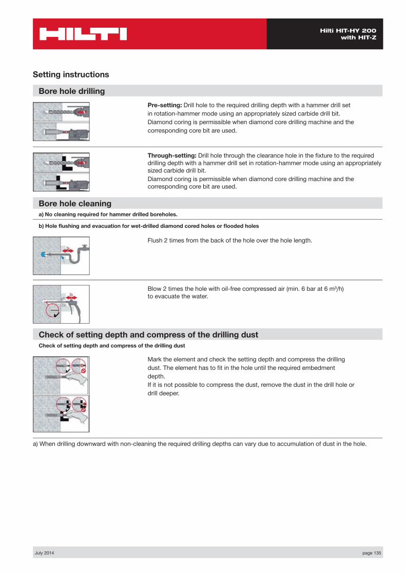
July 2014 page 135
Hilti HIT-HY 200 with HIT-Z
Setting instructions
Bore hole drillingPre-setting: Drill hole to the required drilling depth with a hammer drill setin rotation-hammer mode using an appropriately sized carbide drill bit.Diamond coring is permissible when diamond core drilling machine and thecorresponding core bit are used.
Through-setting: Drill hole through the clearance hole in the fi xture to the required drilling depth with a hammer drill set in rotation-hammer mode using an appropriately sized carbide drill bit.Diamond coring is permissible when diamond core drilling machine and the corresponding core bit are used.
Bore hole cleaning a) No cleaning required for hammer drilled boreholes.
b) Hole fl ushing and evacuation for wet-drilled diamond cored holes or fl ooded holes
Flush 2 times from the back of the hole over the hole length.
Blow 2 times the hole with oil-free compressed air (min. 6 bar at 6 m³/h) to evacuate the water.
Check of setting depth and compress of the drilling dustCheck of setting depth and compress of the drilling dust
Mark the element and check the setting depth and compress the drillingdust. The element has to fi t in the hole until the required embedmentdepth.If it is not possible to compress the dust, remove the dust in the drill hole ordrill deeper.
a) When drilling downward with non-cleaning the required drilling depths can vary due to accumulation of dust in the hole.
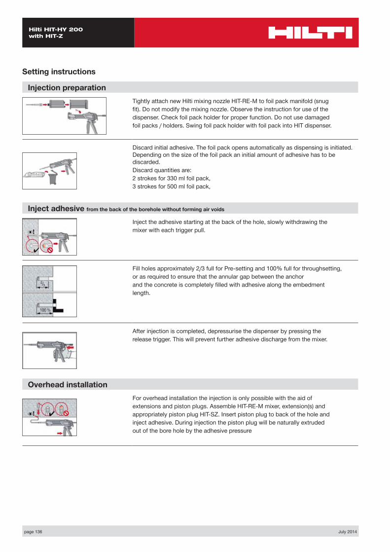
page 136 July 2014
Hilti HIT-HY 200 with HIT-Z
Setting instructions
Injection preparationTightly attach new Hilti mixing nozzle HIT-RE-M to foil pack manifold (snugfit). Do not modify the mixing nozzle. Observe the instruction for use of thedispenser. Check foil pack holder for proper function. Do not use damagedfoil packs / holders. Swing foil pack holder with foil pack into HIT dispenser.
Discard initial adhesive. The foil pack opens automatically as dispensing is initiated. Depending on the size of the foil pack an initial amount of adhesive has to be discarded.Discard quantities are:2 strokes for 330 ml foil pack,3 strokes for 500 ml foil pack,
Inject adhesive from the back of the borehole without forming air voids
Inject the adhesive starting at the back of the hole, slowly withdrawing themixer with each trigger pull.
Fill holes approximately 2/3 full for Pre-setting and 100% full for throughsetting,or as required to ensure that the annular gap between the anchorand the concrete is completely filled with adhesive along the embedmentlength.
After injection is completed, depressurise the dispenser by pressing therelease trigger. This will prevent further adhesive discharge from the mixer.
Overhead installationFor overhead installation the injection is only possible with the aid ofextensions and piston plugs. Assemble HIT-RE-M mixer, extension(s) andappropriately piston plug HIT-SZ. Insert piston plug to back of the hole andinject adhesive. During injection the piston plug will be naturally extrudedout of the bore hole by the adhesive pressure
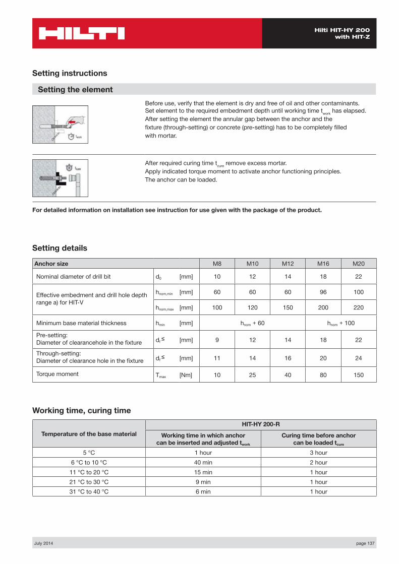
July 2014 page 137
Hilti HIT-HY 200 with HIT-Z
Anchor size M8 M10 M12 M16 M20
Nominal diameter of drill bit d0 [mm] 10 12 14 18 22
Effective embedment and drill hole depth range a) for HIT-V
hnom,min [mm] 60 60 60 96 100
hnom,max [mm] 100 120 150 200 220
Minimum base material thickness hmin [mm] hnom + 60 hnom + 100
Pre-setting: Diameter of clearancehole in the fixture df ≤ [mm] 9 12 14 18 22
Through-setting: Diameter of clearance hole in the fixture df ≤ [mm] 11 14 16 20 24
Torque moment Tmax [Nm] 10 25 40 80 150
Setting details
Working time, curing time
Temperature of the base materialHIT-HY 200-R
Working time in which anchor can be inserted and adjusted twork
Curing time before anchor can be loaded tcure
5 °C 1 hour 3 hour6 °C to 10 °C 40 min 2 hour
11 °C to 20 °C 15 min 1 hour21 °C to 30 °C 9 min 1 hour31 °C to 40 °C 6 min 1 hour
Setting instructions
Setting the elementBefore use, verify that the element is dry and free of oil and other contaminants. Set element to the required embedment depth until working time twork has elapsed.After setting the element the annular gap between the anchor and thefixture (through-setting) or concrete (pre-setting) has to be completely filledwith mortar.
After required curing time tcure remove excess mortar.Apply indicated torque moment to activate anchor functioning principles.The anchor can be loaded.
For detailed information on installation see instruction for use given with the package of the product.
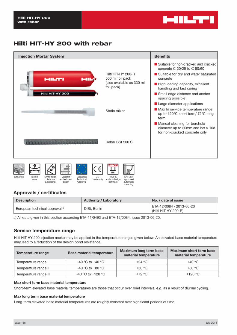
page 138 July 2014
Hilti HIT-HY 200 with rebar
Hilti HIT-HY 200 with rebar
Injection Mortar System Benefits
■ Suitable for non-cracked and cracked concrete C 20/25 to C 50/60
■ Suitable for dry and water saturated concrete
■ High loading capacity, excellent handling and fast curing
■ Small edge distance and anchor spacing possible
■ Large diameter applications■ Max In service temperature range
up to 120°C short term/ 72°C long term
■ Manual cleaning for borehole diameter up to 20mm and hef ≤ 10d for non-cracked concrete only
Approvals / certificatesDescription Authority / Laboratory No. / date of issue
European technical approval a) DIBt, Berlin ETA-12/0084 / 2013-06-20 (Hilti HIT-HY 200-R)
a) All data given in this section according ETA-11/0493 and ETA-12/0084, issue 2013-06-20.
Service temperature rangeHilti HIT-HY 200 injection mortar may be applied in the temperature ranges given below. An elevated base material temperature may lead to a reduction of the design bond resistance.
Temperature range Base material temperature Maximum long term base material temperature
Maximum short term base material temperature
Temperature range I -40 °C to +40 °C +24 °C +40 °CTemperature range II -40 °C to +80 °C +50 °C +80 °CTemperature range III -40 °C to +120 °C +72 °C +120 °C
Max short term base material temperatureShort-term elevated base material temperatures are those that occur over brief intervals, e.g. as a result of diurnal cycling.
Max long term base material temperatureLong-term elevated base material temperatures are roughly constant over significant periods of time
Hilti HIT-HY 200-R500 ml foil pack(also available as 330 ml foil pack)
Static mixer
Rebar BSt 500 S
CE conformity
Small edge distance
& spacing
European Technical Approval
Concrete Variable embedment
depth
Tensile zone
PROFIS anchor design
software
SAFEset approved automatic cleaning
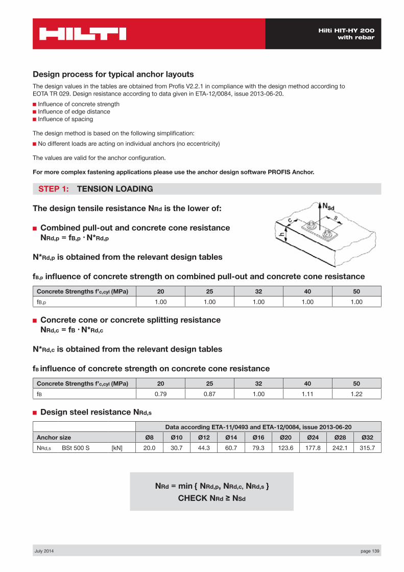
July 2014 page 139
Hilti HIT-HY 200 with rebar
Design process for typical anchor layoutsThe design values in the tables are obtained from Profis V2.2.1 in compliance with the design method according to EOTA TR 029. Design resistance according to data given in ETA-12/0084, issue 2013-06-20.■ Influence of concrete strength ■ Influence of edge distance ■ Influence of spacing
The design method is based on the following simplification:■ No different loads are acting on individual anchors (no eccentricity)
The values are valid for the anchor configuration.
For more complex fastening applications please use the anchor design software PROFIS Anchor.
STEP 1: TENSION LOADING
The design tensile resistance NRd is the lower of:
■ Combined pull-out and concrete cone resistance NRd,p = fB,p • N*Rd,p
N*Rd,p is obtained from the relevant design tables
fB,p influence of concrete strength on combined pull-out and concrete cone resistance
Concrete Strengths f’c,cyl (MPa) 20 25 32 40 50fB,p 1.00 1.00 1.00 1.00 1.00
■ Concrete cone or concrete splitting resistance NRd,c = fB • N*Rd,c
N*Rd,c is obtained from the relevant design tables
fB influence of concrete strength on concrete cone resistance
Concrete Strengths f’c,cyl (MPa) 20 25 32 40 50fB 0.79 0.87 1.00 1.11 1.22
■ Design steel resistance NRd,s
Data according ETA-11/0493 and ETA-12/0084, issue 2013-06-20Anchor size Ø8 Ø10 Ø12 Ø14 Ø16 Ø20 Ø24 Ø28 Ø32NRd,s BSt 500 S [kN] 20.0 30.7 44.3 60.7 79.3 123.6 177.8 242.1 315.7
NRd = min { NRd,p, NRd,c, NRd,s } CHECK NRd ≥ NSd
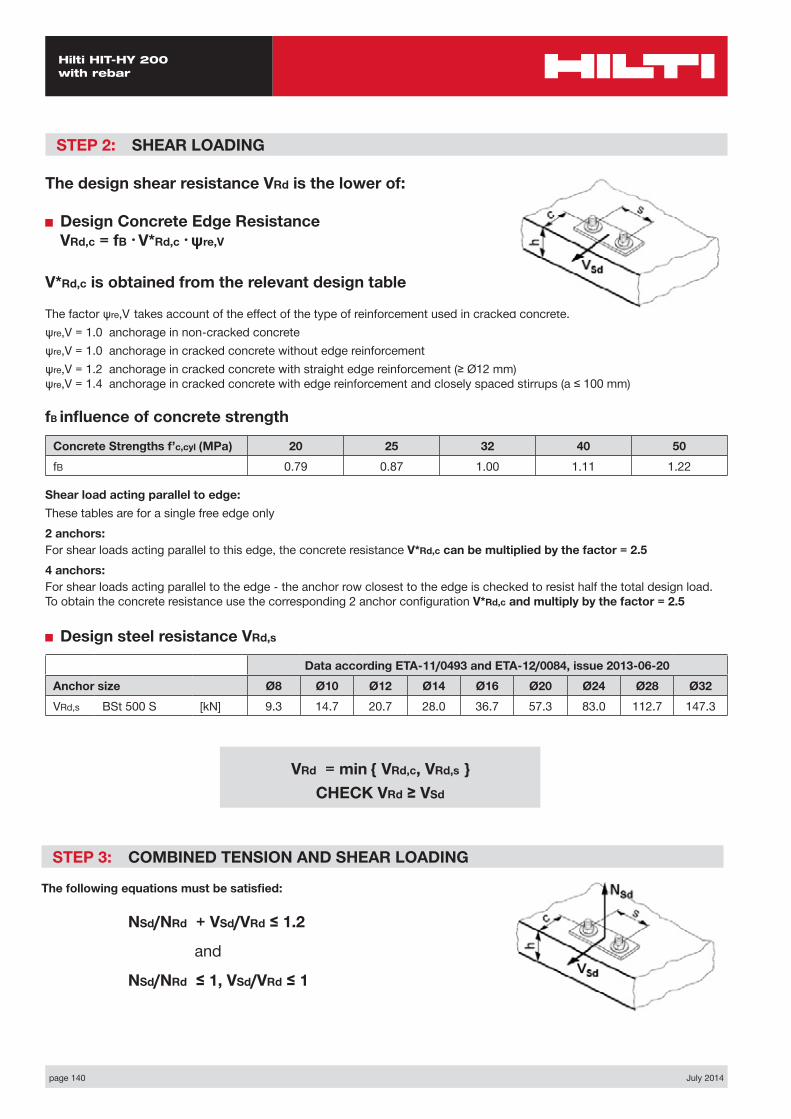
page 140 July 2014
Hilti HIT-HY 200 with rebar
STEP 2: SHEAR LOADING
The design shear resistance VRd is the lower of:
■ Design Concrete Edge Resistance VRd,c = fB • V*Rd,c • ψre,V
V*Rd,c is obtained from the relevant design table
The factor ψre,V takes account of the effect of the type of reinforcement used in cracked concrete.ψre,V = 1.0 anchorage in non-cracked concreteψre,V = 1.0 anchorage in cracked concrete without edge reinforcementψre,V = 1.2 anchorage in cracked concrete with straight edge reinforcement (≥ Ø12 mm) ψre,V = 1.4 anchorage in cracked concrete with edge reinforcement and closely spaced stirrups (a ≤ 100 mm)
fB influence of concrete strength
Concrete Strengths f’c,cyl (MPa) 20 25 32 40 50fB 0.79 0.87 1.00 1.11 1.22
Shear load acting parallel to edge:These tables are for a single free edge only2 anchors:For shear loads acting parallel to this edge, the concrete resistance V*Rd,c can be multiplied by the factor = 2.54 anchors:For shear loads acting parallel to the edge - the anchor row closest to the edge is checked to resist half the total design load. To obtain the concrete resistance use the corresponding 2 anchor configuration V*Rd,c and multiply by the factor = 2.5
■ Design steel resistance VRd,s
Data according ETA-11/0493 and ETA-12/0084, issue 2013-06-20Anchor size Ø8 Ø10 Ø12 Ø14 Ø16 Ø20 Ø24 Ø28 Ø32VRd,s BSt 500 S [kN] 9.3 14.7 20.7 28.0 36.7 57.3 83.0 112.7 147.3
STEP 3: COMBINED TENSION AND SHEAR LOADING
The following equations must be satisfied:
NSd/NRd + VSd/VRd ≤ 1.2
and
NSd/NRd ≤ 1, VSd/VRd ≤ 1
VRd = min { VRd,c, VRd,s } CHECK VRd ≥ VSd
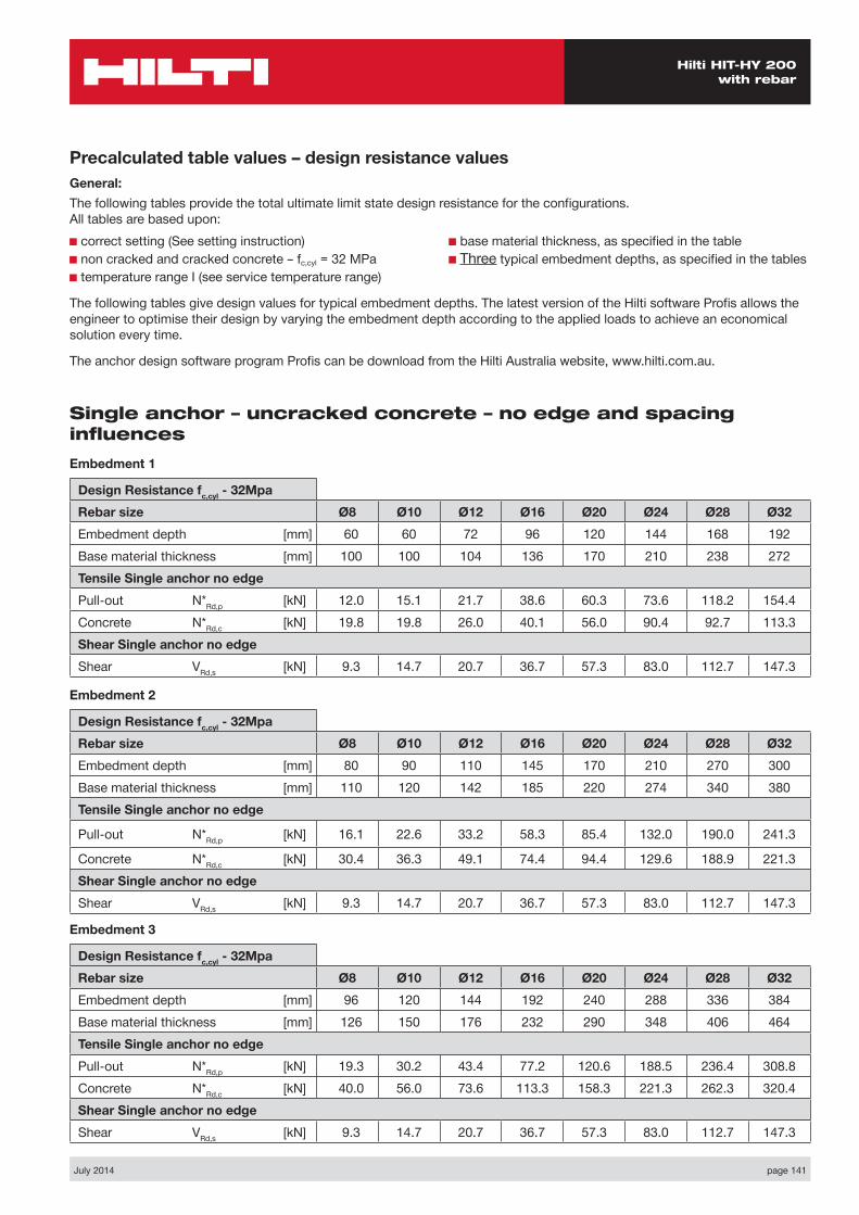
July 2014 page 141
Hilti HIT-HY 200 with rebar
Precalculated table values – design resistance valuesGeneral:The following tables provide the total ultimate limit state design resistance for the configurations. All tables are based upon:■ correct setting (See setting instruction)■ non cracked and cracked concrete – fc,cyl = 32 MPa■ temperature range I (see service temperature range)
■ base material thickness, as specified in the table■ Three typical embedment depths, as specified in the tables
The following tables give design values for typical embedment depths. The latest version of the Hilti software Profis allows the engineer to optimise their design by varying the embedment depth according to the applied loads to achieve an economical solution every time.
The anchor design software program Profis can be download from the Hilti Australia website, www.hilti.com.au.
Single anchor – uncracked concrete – no edge and spacing influencesEmbedment 1
Design Resistance fc,cyl - 32MpaRebar size Ø8 Ø10 Ø12 Ø16 Ø20 Ø24 Ø28 Ø32Embedment depth [mm] 60 60 72 96 120 144 168 192Base material thickness [mm] 100 100 104 136 170 210 238 272Tensile Single anchor no edgePull-out N*Rd,p [kN] 12.0 15.1 21.7 38.6 60.3 73.6 118.2 154.4Concrete N*Rd,c [kN] 19.8 19.8 26.0 40.1 56.0 90.4 92.7 113.3Shear Single anchor no edge Shear VRd,s [kN] 9.3 14.7 20.7 36.7 57.3 83.0 112.7 147.3
Embedment 2
Design Resistance fc,cyl - 32MpaRebar size Ø8 Ø10 Ø12 Ø16 Ø20 Ø24 Ø28 Ø32Embedment depth [mm] 80 90 110 145 170 210 270 300Base material thickness [mm] 110 120 142 185 220 274 340 380Tensile Single anchor no edge
Pull-out N*Rd,p [kN] 16.1 22.6 33.2 58.3 85.4 132.0 190.0 241.3
Concrete N*Rd,c [kN] 30.4 36.3 49.1 74.4 94.4 129.6 188.9 221.3Shear Single anchor no edge Shear VRd,s [kN] 9.3 14.7 20.7 36.7 57.3 83.0 112.7 147.3
Embedment 3
Design Resistance fc,cyl - 32MpaRebar size Ø8 Ø10 Ø12 Ø16 Ø20 Ø24 Ø28 Ø32Embedment depth [mm] 96 120 144 192 240 288 336 384Base material thickness [mm] 126 150 176 232 290 348 406 464Tensile Single anchor no edgePull-out N*Rd,p [kN] 19.3 30.2 43.4 77.2 120.6 188.5 236.4 308.8Concrete N*Rd,c [kN] 40.0 56.0 73.6 113.3 158.3 221.3 262.3 320.4Shear Single anchor no edge Shear VRd,s [kN] 9.3 14.7 20.7 36.7 57.3 83.0 112.7 147.3
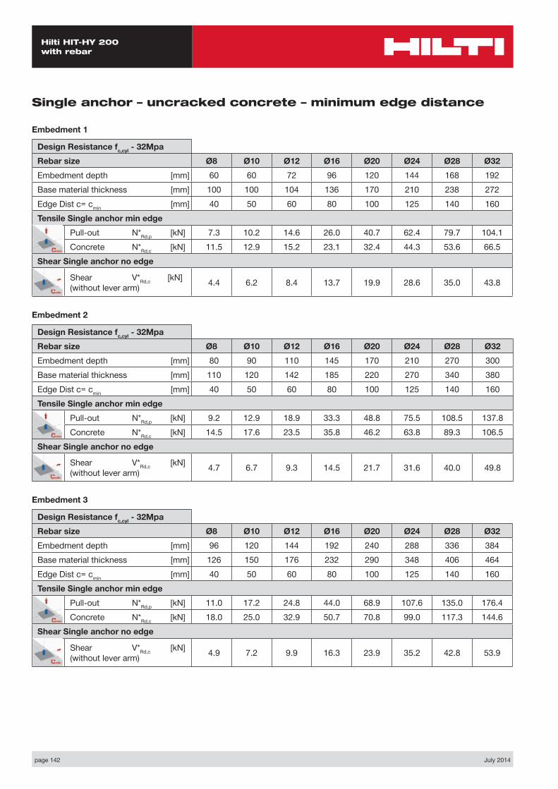
page 142 July 2014
Hilti HIT-HY 200 with rebar
Single anchor – uncracked concrete – minimum edge distance
Embedment 1
Design Resistance fc,cyl - 32MpaRebar size Ø8 Ø10 Ø12 Ø16 Ø20 Ø24 Ø28 Ø32Embedment depth [mm] 60 60 72 96 120 144 168 192Base material thickness [mm] 100 100 104 136 170 210 238 272Edge Dist c= cmin [mm] 40 50 60 80 100 125 140 160Tensile Single anchor min edge
Pull-out N*Rd,p [kN] 7.3 10.2 14.6 26.0 40.7 62.4 79.7 104.1Concrete N*Rd,c [kN] 11.5 12.9 15.2 23.1 32.4 44.3 53.6 66.5
Shear Single anchor no edge
Shear V*Rd,c [kN] (without lever arm) 4.4 6.2 8.4 13.7 19.9 28.6 35.0 43.8
Embedment 2
Design Resistance fc,cyl - 32MpaRebar size Ø8 Ø10 Ø12 Ø16 Ø20 Ø24 Ø28 Ø32Embedment depth [mm] 80 90 110 145 170 210 270 300Base material thickness [mm] 110 120 142 185 220 270 340 380Edge Dist c= cmin [mm] 40 50 60 80 100 125 140 160Tensile Single anchor min edge
Pull-out N*Rd,p [kN] 9.2 12.9 18.9 33.3 48.8 75.5 108.5 137.8Concrete N*Rd,c [kN] 14.5 17.6 23.5 35.8 46.2 63.8 89.3 106.5
Shear Single anchor no edge
Shear V*Rd,c [kN] (without lever arm) 4.7 6.7 9.3 14.5 21.7 31.6 40.0 49.8
Embedment 3
Design Resistance fc,cyl - 32MpaRebar size Ø8 Ø10 Ø12 Ø16 Ø20 Ø24 Ø28 Ø32Embedment depth [mm] 96 120 144 192 240 288 336 384Base material thickness [mm] 126 150 176 232 290 348 406 464Edge Dist c= cmin [mm] 40 50 60 80 100 125 140 160Tensile Single anchor min edge
Pull-out N*Rd,p [kN] 11.0 17.2 24.8 44.0 68.9 107.6 135.0 176.4Concrete N*Rd,c [kN] 18.0 25.0 32.9 50.7 70.8 99.0 117.3 144.6
Shear Single anchor no edge
Shear V*Rd,c [kN] (without lever arm) 4.9 7.2 9.9 16.3 23.9 35.2 42.8 53.9

July 2014 page 143
Hilti HIT-HY 200 with rebar
2 anchors – uncracked concrete – minimum spacing influence
Embedment 1
Design Resistance fc,cyl - 32MpaRebar size Ø8 Ø10 Ø12 Ø16 Ø20 Ø24 Ø28 Ø32Embedment depth [mm] 60 60 72 96 120 144 168 192Base material thickness [mm] 100 100 104 136 170 210 238 272Spacing dist s=smin [mm] 40 50 60 80 100 120 140 160Tensile NRd
Pull-out N*Rd,p [kN] 16.4 20.5 29.0 49.8 77.1 116.6 151.1 197.3Concrete N*Rd,c [kN] 23.9 25.0 31.4 48.2 67.4 90.3 111.6 138.4
Shear VRd VRd,s steel (per anchor) [kN] 9.3 14.7 20.7 36.7 57.3 83.0 112.7 147.3V*Rd,c pryout [kN] N/A 143.1 189.7 237.0 289.5
Embedment 2
Design Resistance fc,cyl - 32MpaRebar size Ø8 Ø10 Ø12 Ø16 Ø20 Ø24 Ø28 Ø32Embedment depth [mm] 80 90 110 145 170 210 270 300Base material thickness [mm] 110 120 142 185 220 270 340 380Spacing dist s=smin [mm] 40 50 60 80 100 125 140 160Tensile NRd
Pull-out N*Rd,p [kN] 22.0 30.2 43.7 74.7 105.5 158.1 227.5 289.0Concrete N*Rd,c [kN] 34.1 41.0 55.1 83.4 106.7 146.7 210.6 250.0
Shear VRd VRd,s (per anchor) [kN] 9.3 14.7 20.7 36.7 57.3 83.0 112.7 147.3
Embedment 3
Design Resistance fc,cyl - 32MpaRebar size Ø8 Ø10 Ø12 Ø16 Ø20 Ø24 Ø28 Ø32Embedment depth [mm] 96 120 144 192 240 288 336 384Base material thickness [mm] 126 150 176 232 290 348 406 464Spacing dist s=smin [mm] 40 50 60 80 100 125 140 160Tensile NRd
Pull-out N*Rd,p [kN] 26.6 41.1 58.5 101.7 155.5 236.5 292.2 373.9Concrete N*Rd,c [kN] 43.8 61.1 80.3 123.7 172.9 241.7 286.4 353.0
Shear VRd VRd,s (per anchor) [kN] 9.3 14.7 20.7 36.7 57.3 83.0 112.7 147.3
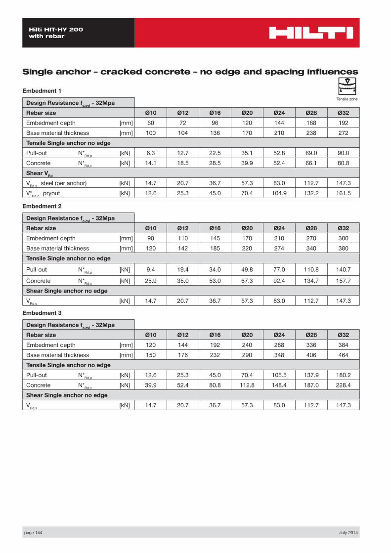
page 144 July 2014
Hilti HIT-HY 200 with rebar
Single anchor – cracked concrete – no edge and spacing influences
Embedment 1
Design Resistance fc,cyl - 32MpaRebar size Ø10 Ø12 Ø16 Ø20 Ø24 Ø28 Ø32Embedment depth [mm] 60 72 96 120 144 168 192Base material thickness [mm] 100 104 136 170 210 238 272Tensile Single anchor no edgePull-out N*Rd,p [kN] 6.3 12.7 22.5 35.1 52.8 69.0 90.0Concrete N*Rd,c [kN] 14.1 18.5 28.5 39.9 52.4 66.1 80.8Shear VRd VRd,s steel (per anchor) [kN] 14.7 20.7 36.7 57.3 83.0 112.7 147.3V*Rd,c pryout [kN] 12.6 25.3 45.0 70.4 104.9 132.2 161.5
Embedment 2
Design Resistance fc,cyl - 32MpaRebar size Ø10 Ø12 Ø16 Ø20 Ø24 Ø28 Ø32Embedment depth [mm] 90 110 145 170 210 270 300Base material thickness [mm] 120 142 185 220 274 340 380Tensile Single anchor no edge
Pull-out N*Rd,p [kN] 9.4 19.4 34.0 49.8 77.0 110.8 140.7
Concrete N*Rd,c [kN] 25.9 35.0 53.0 67.3 92.4 134.7 157.7Shear Single anchor no edge VRd,s [kN] 14.7 20.7 36.7 57.3 83.0 112.7 147.3
Embedment 3
Design Resistance fc,cyl - 32MpaRebar size Ø10 Ø12 Ø16 Ø20 Ø24 Ø28 Ø32Embedment depth [mm] 120 144 192 240 288 336 384Base material thickness [mm] 150 176 232 290 348 406 464Tensile Single anchor no edgePull-out N*Rd,p [kN] 12.6 25.3 45.0 70.4 105.5 137.9 180.2Concrete N*Rd,c [kN] 39.9 52.4 80.8 112.8 148.4 187.0 228.4Shear Single anchor no edge VRd,s [kN] 14.7 20.7 36.7 57.3 83.0 112.7 147.3
Tensile zone
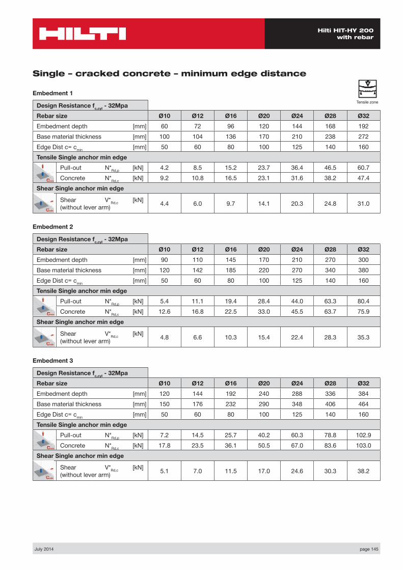
July 2014 page 145
Hilti HIT-HY 200 with rebar
Single – cracked concrete – minimum edge distance
Embedment 1
Design Resistance fc,cyl - 32MpaRebar size Ø10 Ø12 Ø16 Ø20 Ø24 Ø28 Ø32Embedment depth [mm] 60 72 96 120 144 168 192Base material thickness [mm] 100 104 136 170 210 238 272Edge Dist c= cmin [mm] 50 60 80 100 125 140 160Tensile Single anchor min edge
Pull-out N*Rd,p [kN] 4.2 8.5 15.2 23.7 36.4 46.5 60.7Concrete N*Rd,c [kN] 9.2 10.8 16.5 23.1 31.6 38.2 47.4
Shear Single anchor min edge
Shear V*Rd,c [kN] (without lever arm) 4.4 6.0 9.7 14.1 20.3 24.8 31.0
Embedment 2
Design Resistance fc,cyl - 32MpaRebar size Ø10 Ø12 Ø16 Ø20 Ø24 Ø28 Ø32Embedment depth [mm] 90 110 145 170 210 270 300Base material thickness [mm] 120 142 185 220 270 340 380Edge Dist c= cmin [mm] 50 60 80 100 125 140 160Tensile Single anchor min edge
Pull-out N*Rd,p [kN] 5.4 11.1 19.4 28.4 44.0 63.3 80.4Concrete N*Rd,c [kN] 12.6 16.8 22.5 33.0 45.5 63.7 75.9
Shear Single anchor min edge
Shear V*Rd,c [kN] (without lever arm) 4.8 6.6 10.3 15.4 22.4 28.3 35.3
Embedment 3
Design Resistance fc,cyl - 32MpaRebar size Ø10 Ø12 Ø16 Ø20 Ø24 Ø28 Ø32Embedment depth [mm] 120 144 192 240 288 336 384Base material thickness [mm] 150 176 232 290 348 406 464Edge Dist c= cmin [mm] 50 60 80 100 125 140 160Tensile Single anchor min edge
Pull-out N*Rd,p [kN] 7.2 14.5 25.7 40.2 60.3 78.8 102.9Concrete N*Rd,c [kN] 17.8 23.5 36.1 50.5 67.0 83.6 103.0
Shear Single anchor min edge
Shear V*Rd,c [kN] (without lever arm) 5.1 7.0 11.5 17.0 24.6 30.3 38.2
Tensile zone
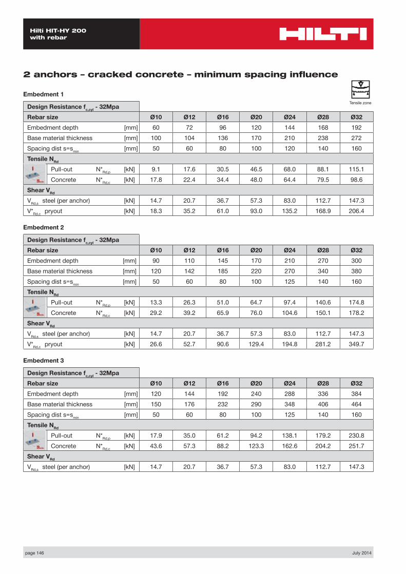
page 146 July 2014
Hilti HIT-HY 200 with rebar
2 anchors – cracked concrete – minimum spacing influence
Embedment 1
Design Resistance fc,cyl - 32MpaRebar size Ø10 Ø12 Ø16 Ø20 Ø24 Ø28 Ø32Embedment depth [mm] 60 72 96 120 144 168 192Base material thickness [mm] 100 104 136 170 210 238 272Spacing dist s=smin [mm] 50 60 80 100 120 140 160Tensile NRd
Pull-out N*Rd,p [kN] 9.1 17.6 30.5 46.5 68.0 88.1 115.1Concrete N*Rd,c [kN] 17.8 22.4 34.4 48.0 64.4 79.5 98.6
Shear VRd VRd,s steel (per anchor) [kN] 14.7 20.7 36.7 57.3 83.0 112.7 147.3V*Rd,c pryout [kN] 18.3 35.2 61.0 93.0 135.2 168.9 206.4
Embedment 2
Design Resistance fc,cyl - 32MpaRebar size Ø10 Ø12 Ø16 Ø20 Ø24 Ø28 Ø32Embedment depth [mm] 90 110 145 170 210 270 300Base material thickness [mm] 120 142 185 220 270 340 380Spacing dist s=smin [mm] 50 60 80 100 125 140 160Tensile NRd
Pull-out N*Rd,p [kN] 13.3 26.3 51.0 64.7 97.4 140.6 174.8Concrete N*Rd,c [kN] 29.2 39.2 65.9 76.0 104.6 150.1 178.2
Shear VRd VRd,s steel (per anchor) [kN] 14.7 20.7 36.7 57.3 83.0 112.7 147.3V*Rd,c pryout [kN] 26.6 52.7 90.6 129.4 194.8 281.2 349.7
Embedment 3
Design Resistance fc,cyl - 32MpaRebar size Ø10 Ø12 Ø16 Ø20 Ø24 Ø28 Ø32Embedment depth [mm] 120 144 192 240 288 336 384Base material thickness [mm] 150 176 232 290 348 406 464Spacing dist s=smin [mm] 50 60 80 100 125 140 160Tensile NRd
Pull-out N*Rd,p [kN] 17.9 35.0 61.2 94.2 138.1 179.2 230.8Concrete N*Rd,c [kN] 43.6 57.3 88.2 123.3 162.6 204.2 251.7
Shear VRd VRd,s steel (per anchor) [kN] 14.7 20.7 36.7 57.3 83.0 112.7 147.3
Tensile zone
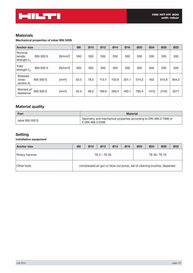
July 2014 page 147
Hilti HIT-HY 200 with rebar
MaterialsMechanical properties of rebar BSt 500S
Anchor size Ø8 Ø10 Ø12 Ø14 Ø16 Ø20 Ø24 Ø28 Ø32
Nominal tensile strength fuk
BSt 500 S [N/mm²] 550 550 550 550 550 550 550 550 550
Yield strength fyk
BSt 500 S [N/mm²] 500 500 500 500 500 500 500 500 500
Stressed cross- section As
BSt 500 S [mm²] 50.3 78.5 113.1 153.9 201.1 314.2 452 615.8 804.2
Moment of resistance BSt 500 S [mm³] 50.3 98.2 169.6 269.4 402.1 785.4 1415 2155 3217
Material quality
Part Material
rebar BSt 500 S Geometry and mechanical properties according to DIN 488-2:1986 or E DIN 488-2:2006
Settinginstallation equipment
Anchor size Ø8 Ø10 Ø12 Ø14 Ø16 Ø20 Ø24 Ø28 Ø32
Rotary hammer TE 2 – TE 30 TE 40– TE 70
Other tools compressed air gun or blow out pump, set of cleaning brushes, dispenser
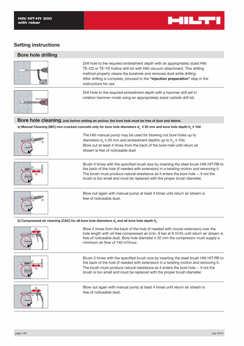
page 148 July 2014
Hilti HIT-HY 200 with rebar
Setting instructions
Bore hole drillingDrill hole to the required embedment depth with an appropriately sized HiltiTE-CD or TE-YD hollow drill bit with Hilti vacuum attachment. This drillingmethod properly cleans the borehole and removes dust while drilling.After drilling is complete, proceed to the “injection preparation” step in theinstructions for use
Drill Hole to the required embedment depth with a hammer drill set inrotation-hammer mode using an appropriately sized carbide drill bit.
Bore hole cleaning Just before setting an anchor, the bore hole must be free of dust and debris.
a) Manual Cleaning (MC) non-cracked concrete only for bore hole diameters d0 ≤ 20 mm and bore hole depth h0 ≤ 10d
The Hilti manual pump may be used for blowing out bore holes up todiameters d0 ≤ 20 mm and embedment depths up to hef ≤ 10d.Blow out at least 4 times from the back of the bore hole until return airstream is free of noticeable dust
Brush 4 times with the specified brush size by inserting the steel brush Hilti HIT-RB to the back of the hole (if needed with extension) in a twisting motion and removing it.The brush must produce natural resistance as it enters the bore hole -- if not the brush is too small and must be replaced with the proper brush diameter.
Blow out again with manual pump at least 4 times until return air stream isfree of noticeable dust.
b) Compressed air cleaning (CAC) for all bore hole diameters d0 and all bore hole depth h0
Blow 2 times from the back of the hole (if needed with nozzle extension) over the hole length with oil-free compressed air (min. 6 bar at 6 m³/h) until return air stream is free of noticeable dust. Bore hole diameter ≥ 32 mm the compressor must supply a minimum air flow of 140 m³/hour.
Brush 2 times with the specified brush size by inserting the steel brush Hilti HIT-RB to the back of the hole (if needed with extension) in a twisting motion and removing it.The brush must produce natural resistance as it enters the bore hole -- if not the brush is too small and must be replaced with the proper brush diameter.
Blow out again with manual pump at least 4 times until return air stream isfree of noticeable dust.
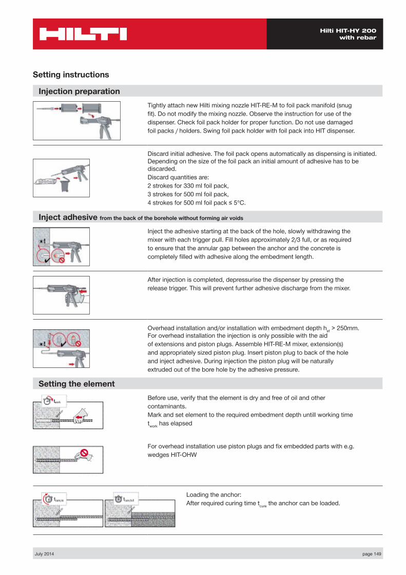
July 2014 page 149
Hilti HIT-HY 200 with rebar
Setting instructions
Injection preparationTightly attach new Hilti mixing nozzle HIT-RE-M to foil pack manifold (snugfit). Do not modify the mixing nozzle. Observe the instruction for use of thedispenser. Check foil pack holder for proper function. Do not use damagedfoil packs / holders. Swing foil pack holder with foil pack into HIT dispenser.
Discard initial adhesive. The foil pack opens automatically as dispensing is initiated. Depending on the size of the foil pack an initial amount of adhesive has to be discarded.Discard quantities are:2 strokes for 330 ml foil pack,3 strokes for 500 ml foil pack,4 strokes for 500 ml foil pack ≤ 5°C.
Inject adhesive from the back of the borehole without forming air voids
Inject the adhesive starting at the back of the hole, slowly withdrawing themixer with each trigger pull. Fill holes approximately 2/3 full, or as requiredto ensure that the annular gap between the anchor and the concrete iscompletely filled with adhesive along the embedment length.
After injection is completed, depressurise the dispenser by pressing therelease trigger. This will prevent further adhesive discharge from the mixer.
Overhead installation and/or installation with embedment depth hef > 250mm. For overhead installation the injection is only possible with the aidof extensions and piston plugs. Assemble HIT-RE-M mixer, extension(s)and appropriately sized piston plug. Insert piston plug to back of the holeand inject adhesive. During injection the piston plug will be naturallyextruded out of the bore hole by the adhesive pressure.
Setting the elementBefore use, verify that the element is dry and free of oil and othercontaminants.Mark and set element to the required embedment depth untill working timetwork has elapsed
For overhead installation use piston plugs and fix embedded parts with e.g.wedges HIT-OHW
Loading the anchor:After required curing time tcure the anchor can be loaded.
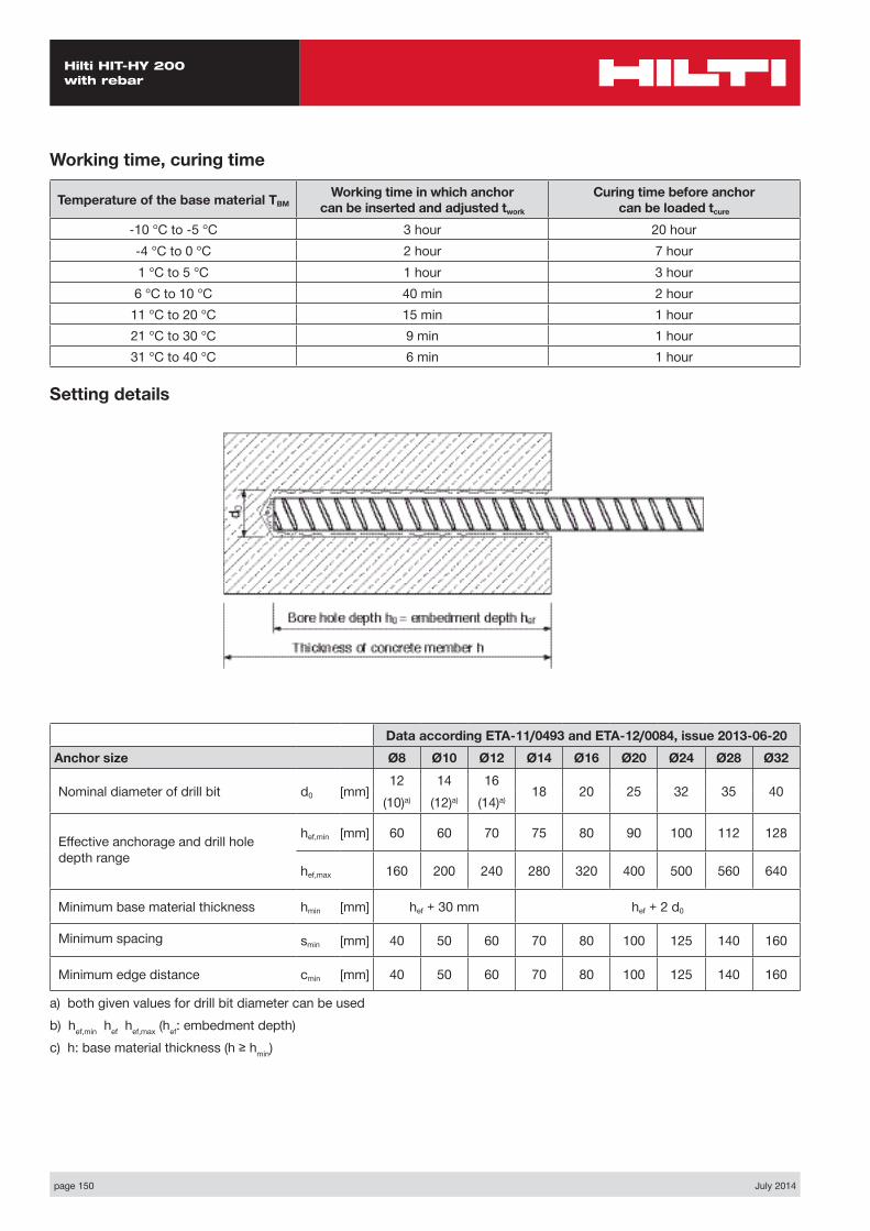
page 150 July 2014
Hilti HIT-HY 200 with rebar
Data according ETA-11/0493 and ETA-12/0084, issue 2013-06-20Anchor size Ø8 Ø10 Ø12 Ø14 Ø16 Ø20 Ø24 Ø28 Ø32
Nominal diameter of drill bit d0 [mm]12 14 16
18 20 25 32 35 40(10)a) (12)a) (14)a)
Effective anchorage and drill hole depth range
hef,min [mm] 60 60 70 75 80 90 100 112 128
hef,max 160 200 240 280 320 400 500 560 640
Minimum base material thickness hmin [mm] hef + 30 mm hef + 2 d0
Minimum spacing smin [mm] 40 50 60 70 80 100 125 140 160
Minimum edge distance cmin [mm] 40 50 60 70 80 100 125 140 160
a) both given values for drill bit diameter can be used b) hef,min hef hef,max (hef: embedment depth)c) h: base material thickness (h ≥ hmin)
Setting details
Working time, curing time
Temperature of the base material TBMWorking time in which anchor
can be inserted and adjusted twork
Curing time before anchor can be loaded tcure
-10 °C to -5 °C 3 hour 20 hour-4 °C to 0 °C 2 hour 7 hour1 °C to 5 °C 1 hour 3 hour6 °C to 10 °C 40 min 2 hour
11 °C to 20 °C 15 min 1 hour21 °C to 30 °C 9 min 1 hour31 °C to 40 °C 6 min 1 hour
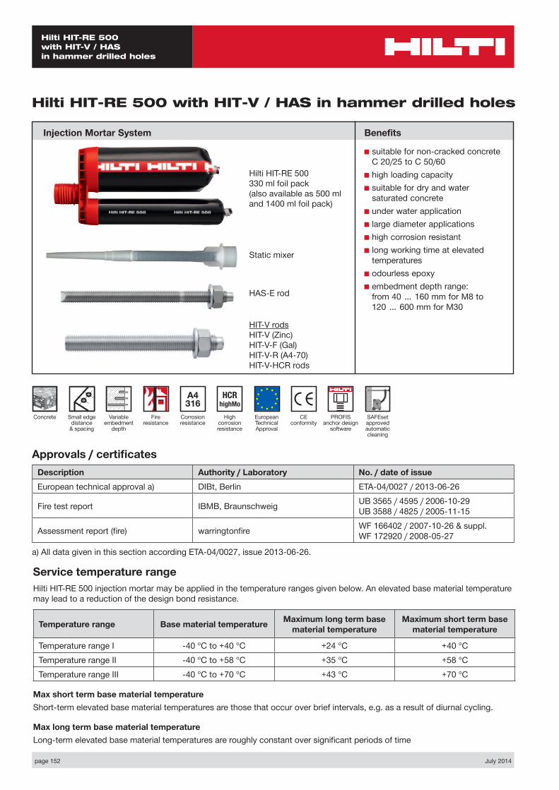
page 152 July 2014
Hilti HIT-RE 500 with HIT-V / HAS in hammer drilled holes
Static mixer
HAS-E rod
CE conformity
Small edge distance
& spacing
European Technical Approval
Concrete
A4 316
Corrosion resistance
HCR highMo
High corrosion resistance
Hilti HIT-RE 500 with HIT-V / HAS in hammer drilled holes
Injection Mortar System
Variable embedment
depth
Hilti HIT-RE 500330 ml foil pack(also available as 500 mland 1400 ml foil pack)
Approvals / certificatesDescription Authority / Laboratory No. / date of issueEuropean technical approval a) DIBt, Berlin ETA-04/0027 / 2013-06-26
Fire test report IBMB, Braunschweig UB 3565 / 4595 / 2006-10-29 UB 3588 / 4825 / 2005-11-15
Assessment report (fire) warringtonfire WF 166402 / 2007-10-26 & suppl. WF 172920 / 2008-05-27
a) All data given in this section according ETA-04/0027, issue 2013-06-26.
Service temperature rangeHilti HIT-RE 500 injection mortar may be applied in the temperature ranges given below. An elevated base material temperature may lead to a reduction of the design bond resistance.
Temperature range Base material temperature Maximum long term base material temperature
Maximum short term base material temperature
Temperature range I -40 °C to +40 °C +24 °C +40 °CTemperature range II -40 °C to +58 °C +35 °C +58 °CTemperature range III -40 °C to +70 °C +43 °C +70 °C
Max short term base material temperatureShort-term elevated base material temperatures are those that occur over brief intervals, e.g. as a result of diurnal cycling.
Max long term base material temperatureLong-term elevated base material temperatures are roughly constant over significant periods of time
Benefits
■ suitable for non-cracked concrete C 20/25 to C 50/60
■ high loading capacity■ suitable for dry and water
saturated concrete■ under water application■ large diameter applications■ high corrosion resistant■ long working time at elevated
temperatures■ odourless epoxy■ embedment depth range:
from 40 … 160 mm for M8 to 120 … 600 mm for M30
Fire resistance
PROFIS anchor design
software
HIT-V rodsHIT-V (Zinc)HIT-V-F (Gal)HIT-V-R (A4-70)HIT-V-HCR rods
SAFEset approved automatic cleaning
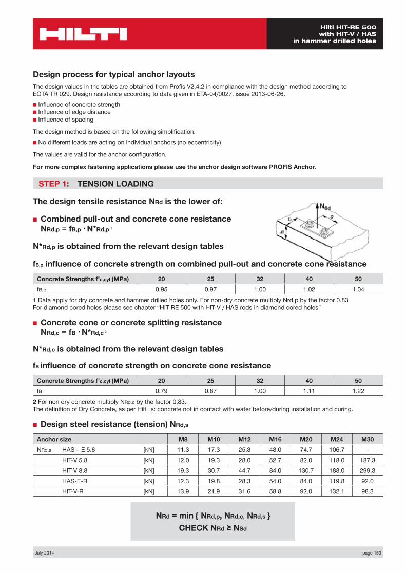
July 2014 page 153
Hilti HIT-RE 500 with HIT-V / HAS
in hammer drilled holes
Design process for typical anchor layoutsThe design values in the tables are obtained from Profis V2.4.2 in compliance with the design method according to EOTA TR 029. Design resistance according to data given in ETA-04/0027, issue 2013-06-26.■ Influence of concrete strength ■ Influence of edge distance ■ Influence of spacing
The design method is based on the following simplification:■ No different loads are acting on individual anchors (no eccentricity)
The values are valid for the anchor configuration.
For more complex fastening applications please use the anchor design software PROFIS Anchor.
STEP 1: TENSION LOADING
The design tensile resistance NRd is the lower of:
■ Combined pull-out and concrete cone resistance NRd,p = fB,p • N*Rd,p 1
N*Rd,p is obtained from the relevant design tables
fB,p influence of concrete strength on combined pull-out and concrete cone resistance
Concrete Strengths f’c,cyl (MPa) 20 25 32 40 50fB,p 0.95 0.97 1.00 1.02 1.04
1 Data apply for dry concrete and hammer drilled holes only. For non-dry concrete multiply Nrd,p by the factor 0.83 For diamond cored holes please see chapter “HIT-RE 500 with HIT-V / HAS rods in diamond cored holes”
■ Concrete cone or concrete splitting resistance NRd,c = fB • N*Rd,c 2
N*Rd,c is obtained from the relevant design tables
fB influence of concrete strength on concrete cone resistance
Concrete Strengths f’c,cyl (MPa) 20 25 32 40 50fB 0.79 0.87 1.00 1.11 1.22
2 For non dry concrete multiply NRd,c by the factor 0.83. The definition of Dry Concrete, as per Hilti is: concrete not in contact with water before/during installation and curing.
■ Design steel resistance (tension) NRd,s
Anchor size M8 M10 M12 M16 M20 M24 M30NRd,s HAS – E 5.8 [kN] 11.3 17.3 25.3 48.0 74.7 106.7 -
HIT-V 5.8 [kN] 12.0 19.3 28.0 52.7 82.0 118.0 187.3HIT-V 8.8 [kN] 19.3 30.7 44.7 84.0 130.7 188.0 299.3HAS-E-R [kN] 12.3 19.8 28.3 54.0 84.0 119.8 92.0HIT-V-R [kN] 13.9 21.9 31.6 58.8 92.0 132.1 98.3
NRd = min { NRd,p, NRd,c, NRd,s } CHECK NRd ≥ NSd
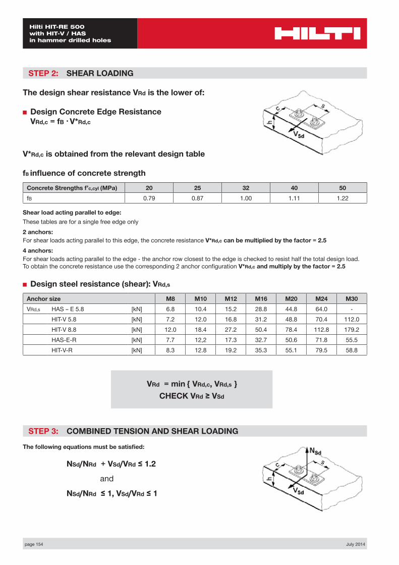
page 154 July 2014
Hilti HIT-RE 500 with HIT-V / HAS in hammer drilled holes
STEP 2: SHEAR LOADING
The design shear resistance VRd is the lower of:
■ Design Concrete Edge Resistance VRd,c = fB • V*Rd,c
V*Rd,c is obtained from the relevant design table
fB influence of concrete strength
Concrete Strengths f’c,cyl (MPa) 20 25 32 40 50fB 0.79 0.87 1.00 1.11 1.22
Shear load acting parallel to edge:These tables are for a single free edge only2 anchors:For shear loads acting parallel to this edge, the concrete resistance V*Rd,c can be multiplied by the factor = 2.54 anchors:For shear loads acting parallel to the edge - the anchor row closest to the edge is checked to resist half the total design load. To obtain the concrete resistance use the corresponding 2 anchor configuration V*Rd,c and multiply by the factor = 2.5
■ Design steel resistance (shear): VRd,s
Anchor size M8 M10 M12 M16 M20 M24 M30VRd,s HAS – E 5.8 [kN] 6.8 10.4 15.2 28.8 44.8 64.0 -
HIT-V 5.8 [kN] 7.2 12.0 16.8 31.2 48.8 70.4 112.0HIT-V 8.8 [kN] 12.0 18.4 27.2 50.4 78.4 112.8 179.2HAS-E-R [kN] 7.7 12,2 17.3 32.7 50.6 71.8 55.5HIT-V-R [kN] 8.3 12.8 19.2 35.3 55.1 79.5 58.8
STEP 3: COMBINED TENSION AND SHEAR LOADING
The following equations must be satisfied:
NSd/NRd + VSd/VRd ≤ 1.2
and
NSd/NRd ≤ 1, VSd/VRd ≤ 1
VRd = min { VRd,c, VRd,s } CHECK VRd ≥ VSd
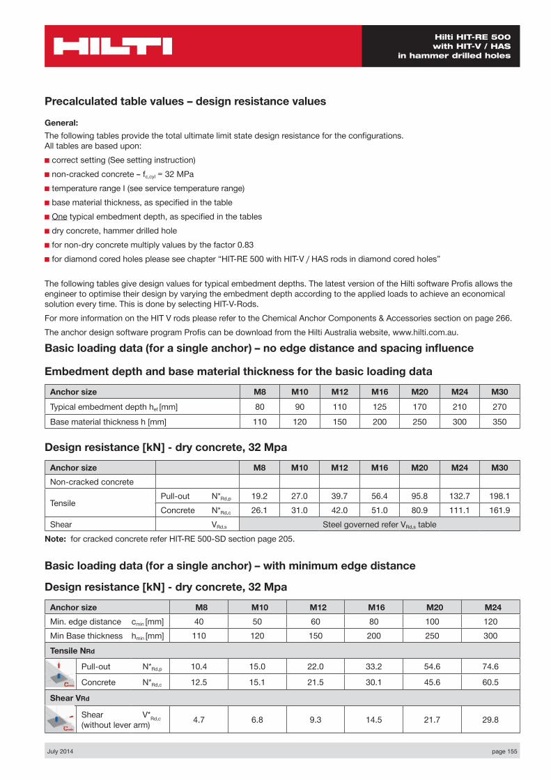
July 2014 page 155
Hilti HIT-RE 500 with HIT-V / HAS
in hammer drilled holes
Basic loading data (for a single anchor) – no edge distance and spacing influence
Embedment depth and base material thickness for the basic loading data
Anchor size M8 M10 M12 M16 M20 M24 M30
Typical embedment depth hef [mm] 80 90 110 125 170 210 270
Base material thickness h [mm] 110 120 150 200 250 300 350
Precalculated table values – design resistance values
General:The following tables provide the total ultimate limit state design resistance for the configurations. All tables are based upon:■ correct setting (See setting instruction)■ non-cracked concrete – fc,cyl = 32 MPa■ temperature range I (see service temperature range)■ base material thickness, as specified in the table■ One typical embedment depth, as specified in the tables■ dry concrete, hammer drilled hole■ for non-dry concrete multiply values by the factor 0.83■ for diamond cored holes please see chapter “HIT-RE 500 with HIT-V / HAS rods in diamond cored holes”
The following tables give design values for typical embedment depths. The latest version of the Hilti software Profis allows the engineer to optimise their design by varying the embedment depth according to the applied loads to achieve an economical solution every time. This is done by selecting HIT-V-Rods.For more information on the HIT V rods please refer to the Chemical Anchor Components & Accessories section on page 266.The anchor design software program Profis can be download from the Hilti Australia website, www.hilti.com.au.
Design resistance [kN] - dry concrete, 32 Mpa
Anchor size M8 M10 M12 M16 M20 M24 M30Non-cracked concrete
Tensile Pull-out N*Rd,p 19.2 27.0 39.7 56.4 95.8 132.7 198.1Concrete N*Rd,c 26.1 31.0 42.0 51.0 80.9 111.1 161.9
Shear VRd,s Steel governed refer VRd,s tableNote: for cracked concrete refer HIT-RE 500-SD section page 205.
Basic loading data (for a single anchor) – with minimum edge distance
Design resistance [kN] - dry concrete, 32 Mpa
Anchor size M8 M10 M12 M16 M20 M24Min. edge distance cmin [mm] 40 50 60 80 100 120Min Base thickness hmin [mm] 110 120 150 200 250 300
Tensile NRd
Pull-out N*Rd,p 10.4 15.0 22.0 33.2 54.6 74.6
Concrete N*Rd,c 12.5 15.1 21.5 30.1 45.6 60.5
Shear VRd
Shear V*Rd,c (without lever arm) 4.7 6.8 9.3 14.5 21.7 29.8

page 156 July 2014
Hilti HIT-RE 500 with HIT-V / HAS in hammer drilled holes
Nsd
Vsd
S1
C
h
Two Anchors Table 1: One edge influence
Design Data: fc,cyl=32 MPa
Anchor size M8 M10 M12 M16 M20 M24Typical embedment depth hef [mm] 80 90 110 125 170 210
Base material thickness h [mm] 110 120 150 200 250 300
ANCHOR
M8Edge C (mm)
40 80 100 150 170spacings1 (mm)
tension shear tension shear tension shear tension shear tension shearN*Rd,p N*Rd,c V*Rrd,c N*Rd,p N*Rd,c V*Rrd,c N*Rd,p N*Rd,c V*Rrd,c N*Rd,p N*Rd,c V*Rrd,c N*Rd,p N*Rd,c V*Rrd,c
40 13.2 13.9 6.3 18.7 18.1 13.2 21.8 20.3 15.4 24.5 26.5 21.0 24.6 29.2 23.2
80 14.8 15.4 7.9 21.0 19.9 15.0 24.4 22.4 17.2 27.5 29.3 22.7 27.5 32.3 24.9
100 15.6 16.1 8.6 22.1 20.9 15.9 25.7 23.5 18.1 28.6 30.7 23.6 28.9 33.8 25.7
120 16.3 16.8 9.4 23.2 21.8 16.9 27.0 24.6 19.0 30.4 32.0 24.5 30.4 35.3 26.6
150 17.5 17.9 9.4 24.8 23.3 18.3 28.9 26.2 20.4 32.5 34.2 25.7 32.5 37.7 27.9
200 19.4 19.8 9.4 27.6 25.7 20.6 32.0 28.9 22.6 36.1 37.7 27.9 36.1 41.5 30.0
ANCHOR
M10Edge C (mm)
50 80 100 150 200spacings1 (mm)
tension shear tension shear tension shear tension shear tension shearN*Rd,p N*Rd,c V*Rrd,c N*Rd,p N*Rd,c V*Rrd,c N*Rd,p N*Rd,c V*Rrd,c N*Rd,p N*Rd,c V*Rrd,c N*Rd,p N*Rd,c V*Rrd,c
50 18.6 17.0 9.0 23.4 20.3 15.0 26.9 22.4 17.4 33.5 28.6 23.4 33.5 35.2 29.3
100 21.2 19.0 11.3 26.8 22.6 17.6 30.7 25.1 19.9 38.3 31.8 25.7 38.3 39.0 31.5
150 23.9 20.9 13.5 30.0 24.7 20.2 34.4 27.5 22.4 43.0 35.0 28.1 43.0 43.0 33.8
200 26.5 22.8 13.5 33.4 27.0 22.8 38.3 30.1 24.9 47.6 38.3 30.4 47.6 46.9 36.1
250 29.0 24.7 13.5 36.6 29.3 24.8 42.0 32.5 27.4 52.3 41.4 32.7 52.3 50.8 38.3
300 30.1 26.6 13.5 37.9 31.6 24.8 43.4 35.2 29.9 54.2 44.6 35.1 54.2 54.7 40.6
ANCHOR
M12Edge C (mm)
60 80 100 150 200spacings1 (mm)
tension shear tension shear tension shear tension shear tension shearN*Rd,p N*Rd,c V*Rrd,c N*Rd,p N*Rd,c V*Rrd,c N*Rd,p N*Rd,c V*Rrd,c N*Rd,p N*Rd,c V*Rrd,c N*Rd,p N*Rd,c V*Rrd,c
60 26.4 24.2 12.3 30.0 26.6 16.7 33.8 29.3 21.4 44.4 36.2 28.2 47.9 43.8 35.0
100 28.9 26.0 14.4 33.0 28.7 18.9 37.2 31.4 23.8 48.7 38.9 30.5 52.6 47.2 37.1
150 32.2 28.3 16.9 36.6 31.2 21.7 41.4 34.2 26.7 54.2 42.4 33.2 58.4 51.2 39.7
200 35.4 30.6 18.5 40.3 33.7 24.5 45.5 37.0 29.7 59.6 45.7 36.0 64.2 55.3 42.4
250 38.6 32.9 18.5 44.0 36.2 26.7 49.7 39.7 32.7 65.2 49.1 38.7 70.1 59.4 45.0
300 41.9 35.2 18.5 47.6 38.8 26.7 53.8 42.5 35.7 70.6 52.6 41.5 76.0 63.6 47.7

July 2014 page 157
Hilti HIT-RE 500 with HIT-V / HAS
in hammer drilled holes
ANCHOR
M24Edge C (mm)
120 150 200 250 350spacings1 (mm)
tension shear tension shear tension shear tension shear tension shearN*Rd,p N*Rd,c V*Rrd,c N*Rd,p N*Rd,c V*Rrd,c N*Rd,p N*Rd,c V*Rrd,c N*Rd,p N*Rd,c V*Rrd,c N*Rd,p N*Rd,c V*Rrd,c
120 88.9 69.0 39.7 98.3 74.8 49.7 115.1 84.8 67.5 133.0 95.4 77.6 158.0 118.3 97.6
150 92.4 71.2 42.3 102.2 77.0 52.3 119.6 87.5 70.3 138.2 98.4 80.2 164.4 122.0 100.1
200 98.4 74.8 46.4 108.8 81.0 56.6 127.3 91.8 75.0 147.1 103.3 84.7 174.8 128.2 104.2
250 104.3 78.2 50.5 115.3 84.8 61.0 135.0 96.1 79.6 156.0 108.2 89.2 185.4 134.2 108.4
300 110.2 81.8 54.7 121.9 88.7 65.3 142.7 100.6 84.3 164.9 113.2 93.6 196.0 140.2 112.6
350 116.2 85.3 58.8 128.5 92.5 69.7 150.4 104.9 89.0 173.8 118.1 98.1 206.5 146.4 116.8
ANCHOR
M16Edge C (mm)
80 100 150 200 250spacings1 (mm)
tension shear tension shear tension shear tension shear tension shearN*Rd,p N*Rd,c V*Rrd,c N*Rd,p N*Rd,c V*Rrd,c N*Rd,p N*Rd,c V*Rrd,c N*Rd,p N*Rd,c V*Rrd,c N*Rd,p N*Rd,c V*Rrd,c
80 40.4 36.6 19.3 45.1 40.8 24.4 58.0 52.3 36.2 68.5 61.9 44.1 68.5 61.9 52.0
100 42.2 38.2 20.5 47.2 42.6 25.7 60.5 54.7 37.5 71.5 64.6 45.4 71.5 64.6 53.2
150 46.7 42.2 23.6 52.1 47.0 28.9 66.8 60.5 41.0 79.1 71.4 48.6 79.1 71.4 56.3
200 51.1 46.2 26.6 57.1 51.6 32.1 73.2 66.1 44.4 86.5 78.2 51.9 86.5 78.2 59.4
250 55.6 50.3 29.0 62.0 56.0 35.3 79.6 71.9 47.8 94.1 85.1 55.1 94.1 85.1 62.6
300 60.0 54.2 29.0 67.0 60.6 38.6 85.9 77.3 51.2 101.6 91.8 58.4 101.6 91.8 65.7
ANCHOR
M20Edge C (mm)
120 150 200 250 300spacings1 (mm)
tension shear tension shear tension shear tension shear tension shearN*Rd,p N*Rd,c V*Rrd,c N*Rd,p N*Rd,c V*Rrd,c N*Rd,p N*Rd,c V*Rrd,c N*Rd,p N*Rd,c V*Rrd,c N*Rd,p N*Rd,c V*Rrd,c
100 65.3 52.4 28.9 79.8 61.9 44.0 95.8 72.0 55.5 113.0 82.8 64.6 114.7 94.3 73.5
150 70.7 55.9 32.5 86.4 65.9 48.0 103.6 76.7 59.5 122.3 88.2 68.4 124.2 100.4 77.2
200 76.1 59.3 36.1 93.0 70.0 52.0 111.5 81.4 63.5 131.5 93.6 72.2 133.6 106.1 80.9
250 81.4 62.8 39.7 99.5 74.0 56.0 119.3 86.2 67.4 140.8 99.0 76.0 143.0 112.8 84.6
300 86.8 66.1 43.4 106.1 78.0 60.0 127.2 90.8 71.4 150.0 104.4 79.8 152.4 118.9 88.2
350 92.0 69.6 43.4 112.7 82.1 64.0 135.0 95.5 75.4 159.2 109.8 83.6 161.8 125.2 92.0

page 158 July 2014
Hilti HIT-RE 500 with HIT-V / HAS in hammer drilled holes
Four anchors Table 2: One edge influence
Design Data: fc,cyl=32 MPa
Anchor size M8 M10 M12 M16 M20 M24Typical embedment depth hef [mm] 80 90 110 125 170 210
Base material thickness h [mm] 110 120 150 200 250 300
ANCHOR
M8Edge C (mm)
40 80 100 150 200spacing
s1=s2 (mm)
tension shear tension shear tension shear tension shear tension shearN*Rd,p N*Rd,c V*Rrd,c N*Rd,p N*Rd,c V*Rrd,c N*Rd,p N*Rd,c V*Rrd,c N*Rd,p N*Rd,c V*Rrd,c N*Rd,p N*Rd,c V*Rrd,c
40 18.5 16.6 12.6 25.1 21.0 17.7 28.8 23.3 19.9 32.0 29.8 25.4 32.0 32.6 30.9
80 24.1 21.2 15.8 31.9 26.4 23.8 36.1 29.2 26.0 40.0 36.6 31.5 40.0 39.8 36.8
100 27.4 23.8 17.2 35.6 29.3 26.8 40.1 32.3 29.0 44.2 40.3 34.4 44.2 43.8 39.7
120 30.6 26.4 18.8 39.5 32.4 29.8 44.3 35.5 32.0 48.7 44.2 37.3 48.7 47.8 42.6
150 35.8 30.7 18.8 45.6 37.2 34.3 50.9 40.8 36.4 55.7 50.2 41.7 55.7 54.2 47.0
200 45.0 38.5 18.8 56.5 46.2 41.2 62.6 50.3 43.7 68.2 61.2 49.0 68.2 65.9 54.2
ANCHOR
M10Edge C (mm)
50 80 100 150 200spacing
s1=s2 (mm)
tension shear tension shear tension shear tension shear tension shearN*Rd,p N*Rd,c V*Rrd,c N*Rd,p N*Rd,c V*Rrd,c N*Rd,p N*Rd,c V*Rrd,c N*Rd,p N*Rd,c V*Rrd,c N*Rd,p N*Rd,c V*Rrd,c
50 25.1 20.5 17.4 30.6 23.9 21.0 34.6 26.3 23.4 42.0 32.8 29.3 42.0 39.5 35.1
100 34.1 26.6 22.6 40.8 30.6 29.2 45.6 33.4 31.5 54.6 40.9 37.2 54.6 48.8 43.0
150 44.4 33.5 27.0 52.3 38.2 37.2 58.0 41.4 39.4 68.6 50.2 45.1 68.6 59.3 50.7
200 55.9 41.2 27.0 65.2 46.4 45.0 71.9 50.3 47.2 84.2 60.2 52.8 84.2 70.6 58.4
250 68.6 49.6 27.0 79.4 55.7 49.6 87.0 59.3 54.8 101.2 71.2 60.5 101.4 82.9 66.0
300 74.0 58.8 27.0 85.4 65.6 49.6 93.5 70.4 59.8 108.4 83.2 68.0 108.4 96.2 73.5
ANCHOR
M12Edge C (mm)
60 80 100 150 200spacing
s1=s2 (mm)
tension shear tension shear tension shear tension shear tension shearN*Rd,p N*Rd,c V*Rrd,c N*Rd,p N*Rd,c V*Rrd,c N*Rd,p N*Rd,c V*Rrd,c N*Rd,p N*Rd,c V*Rrd,c N*Rd,p N*Rd,c V*Rrd,c
60 34.3 29.0 24.1 38.3 31.8 26.9 42.6 34.4 29.6 54.2 41.9 36.3 58.0 49.8 42.9
100 42.7 34.8 28.8 47.3 37.8 34.4 52.2 40.8 37.1 65.5 49.0 43.6 69.8 58.0 50.1
150 54.5 42.6 33.8 60.0 46.0 43.4 65.8 49.4 46.2 81.2 58.8 52.7 86.2 68.9 59.1
200 67.7 51.2 37.0 74.0 55.1 49.0 80.6 58.9 55.2 98.5 69.5 61.5 104.2 80.8 67.9
250 82.2 60.6 37.0 89.4 64.8 53.4 97.1 69.2 64.0 117.5 81.0 70.3 124.0 93.6 76.6
300 98.0 70.7 37.0 106.3 75.5 53.4 115.0 80.4 71.4 138.0 93.4 79.0 145.3 107.3 85.2
Nsd
Vsd
S2
S1
C
h

July 2014 page 159
Hilti HIT-RE 500 with HIT-V / HAS
in hammer drilled holes
ANCHOR
M24Edge C (mm)
120 150 200 250 350spacing
s1=s2 (mm)
tension shear tension shear tension shear tension shear tension shearN*Rd,p N*Rd,c V*Rrd,c N*Rd,p N*Rd,c V*Rrd,c N*Rd,p N*Rd,c V*Rrd,c N*Rd,p N*Rd,c V*Rrd,c N*Rd,p N*Rd,c V*Rrd,c
120 113.4 84.2 75.5 123.7 90.4 81.6 141.8 101.0 91.6 161.2 111.7 101.5 188.2 136.7 121.2
150 124.3 90.7 84.2 135.2 97.2 90.2 154.6 108.4 100.1 175.0 120.2 109.9 203.5 145.6 129.4
200 143.5 102.1 92.8 155.6 109.1 104.2 176.8 121.2 114.0 199.2 133.8 123.7 230.4 161.0 142.9
250 164.2 114.1 101.0 177.4 121.6 118.0 200.5 134.6 127.7 225.0 148.2 137.2 259.1 177.4 156.3
300 186.2 126.7 109.4 200.6 134.8 130.6 225.7 148.7 141.1 252.5 163.3 150.6 289.3 194.5 169.5
350 208.9 140.0 117.6 225.2 148.7 139.4 252.5 163.6 154.5 281.4 179.2 163.9 321.2 212.4 182.6
ANCHOR
M16Edge C (mm)
80 100 150 200 250spacing
s1=s2 (mm)
tension shear tension shear tension shear tension shear tension shearN*Rd,p N*Rd,c V*Rrd,c N*Rd,p N*Rd,c V*Rrd,c N*Rd,p N*Rd,c V*Rrd,c N*Rd,p N*Rd,c V*Rrd,c N*Rd,p N*Rd,c V*Rrd,c
80 52.6 47.5 37.8 57.7 52.1 40.9 71.6 64.8 48.8 83.2 75.1 56.6 83.2 75.1 64.3
100 58.0 52.4 41.0 63.5 57.5 45.4 78.4 70.9 53.2 90.6 81.8 60.9 90.6 81.8 68.6
150 72.8 65.9 47.2 79.3 71.6 56.3 96.6 86.6 64.0 110.6 100.0 71.5 110.6 100.0 79.1
200 89.4 80.6 53.2 96.7 86.9 64.1 116.6 103.2 74.5 132.7 120.0 82.0 132.7 120.0 89.5
250 107.5 95.9 58.0 115.9 102.8 70.6 138.6 121.2 85.0 156.8 141.1 92.4 156.8 141.7 99.7
300 127.3 112.4 58.0 136.9 120.1 77.2 162.4 140.6 95.2 182.9 163.0 102.6 182.9 165.2 110.0
ANCHOR
M20Edge C (mm)
100 150 200 250 300spacing
s1=s2 (mm)
tension shear tension shear tension shear tension shear tension shearN*Rd,p N*Rd,c V*Rrd,c N*Rd,p N*Rd,c V*Rrd,c N*Rd,p N*Rd,c V*Rrd,c N*Rd,p N*Rd,c V*Rrd,c N*Rd,p N*Rd,c V*Rrd,c
100 83.8 64.6 55.5 99.6 74.6 64.6 116.9 85.4 73.5 135.4 97.0 82.4 137.3 109.2 91.2
150 100.4 75.2 65.0 118.4 86.4 77.2 137.8 98.3 86.0 158.5 110.9 94.7 160.7 124.3 103.4
200 118.9 86.8 72.2 139.0 99.0 89.6 160.4 112.0 98.2 183.6 125.8 106.8 186.0 140.4 115.4
250 138.7 99.0 79.4 160.9 112.4 101.7 184.9 126.6 110.3 210.5 141.6 118.8 213.1 157.4 127.3
300 160.0 112.1 86.8 184.7 126.6 113.7 211.0 142.0 122.2 239.2 158.3 130.7 242.0 175.4 139.1
350 182.9 126.0 86.8 210.0 141.7 125.6 238.9 158.4 134.0 269.6 175.9 142.4 272.9 194.4 150.8
Shear design: The concrete edge resistance value in this table uses all 4 anchors in shear. You will need to ensure the gap between anchor and the plate is filled. This can be achieved using the Hilti Dynamic Set. (Refer page 41 for further details)
The concrete edge resistance values have been obtained by taking the lesser of:1. First row resistance multiplied by number of rows and 2. The concrete edge resistance of the furthest row.
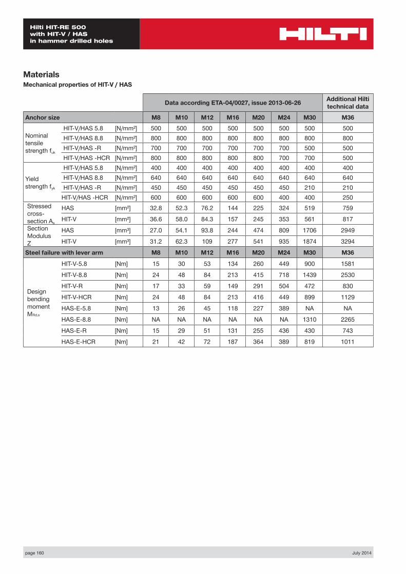
page 160 July 2014
Hilti HIT-RE 500 with HIT-V / HAS in hammer drilled holes
MaterialsMechanical properties of HIT-V / HAS
Data according ETA-04/0027, issue 2013-06-26 Additional Hilti technical data
Anchor size M8 M10 M12 M16 M20 M24 M30 M36
Nominal tensile strength fuk
HIT-V/HAS 5.8 [N/mm²] 500 500 500 500 500 500 500 500HIT-V/HAS 8.8 [N/mm²] 800 800 800 800 800 800 800 800HIT-V/HAS -R [N/mm²] 700 700 700 700 700 700 500 500HIT-V/HAS -HCR [N/mm²] 800 800 800 800 800 700 700 500
Yield strength fyk
HIT-V/HAS 5.8 [N/mm²] 400 400 400 400 400 400 400 400HIT-V/HAS 8.8 [N/mm²] 640 640 640 640 640 640 640 640HIT-V/HAS -R [N/mm²] 450 450 450 450 450 450 210 210
HIT-V/HAS -HCR [N/mm²] 600 600 600 600 600 400 400 250Stressed cross- section As
HAS [mm²] 32.8 52.3 76.2 144 225 324 519 759
HIT-V [mm²] 36.6 58.0 84.3 157 245 353 561 817Section Modulus Z
HAS [mm³] 27.0 54.1 93.8 244 474 809 1706 2949
HIT-V [mm³] 31.2 62.3 109 277 541 935 1874 3294
Steel failure with lever arm M8 M10 M12 M16 M20 M24 M30 M36
Design bending moment MRd,s
HIT-V-5.8 [Nm] 15 30 53 134 260 449 900 1581
HIT-V-8.8 [Nm] 24 48 84 213 415 718 1439 2530
HIT-V-R [Nm] 17 33 59 149 291 504 472 830
HIT-V-HCR [Nm] 24 48 84 213 416 449 899 1129
HAS-E-5.8 [Nm] 13 26 45 118 227 389 NA NA
HAS-E-8.8 [Nm] NA NA NA NA NA NA 1310 2265
HAS-E-R [Nm] 15 29 51 131 255 436 430 743
HAS-E-HCR [Nm] 21 42 72 187 364 389 819 1011
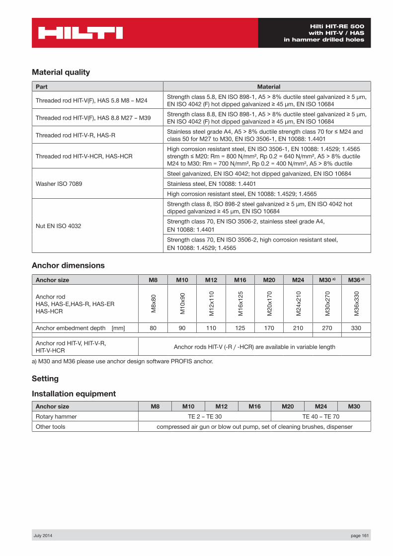
July 2014 page 161
Hilti HIT-RE 500 with HIT-V / HAS
in hammer drilled holes
Material quality
Part Material
Threaded rod HIT-V(F), HAS 5.8 M8 – M24 Strength class 5.8, EN ISO 898-1, A5 > 8% ductile steel galvanized ≥ 5 µm, EN ISO 4042 (F) hot dipped galvanized ≥ 45 µm, EN ISO 10684
Threaded rod HIT-V(F), HAS 8.8 M27 – M39 Strength class 8.8, EN ISO 898-1, A5 > 8% ductile steel galvanized ≥ 5 µm, EN ISO 4042 (F) hot dipped galvanized ≥ 45 µm, EN ISO 10684
Threaded rod HIT-V-R, HAS-R Stainless steel grade A4, A5 > 8% ductile strength class 70 for ≤ M24 and class 50 for M27 to M30, EN ISO 3506-1, EN 10088: 1.4401
Threaded rod HIT-V-HCR, HAS-HCRHigh corrosion resistant steel, EN ISO 3506-1, EN 10088: 1.4529; 1.4565 strength ≤ M20: Rm = 800 N/mm², Rp 0.2 = 640 N/mm², A5 > 8% ductile M24 to M30: Rm = 700 N/mm², Rp 0.2 = 400 N/mm², A5 > 8% ductile
Washer ISO 7089Steel galvanized, EN ISO 4042; hot dipped galvanized, EN ISO 10684Stainless steel, EN 10088: 1.4401High corrosion resistant steel, EN 10088: 1.4529; 1.4565
Nut EN ISO 4032
Strength class 8, ISO 898-2 steel galvanized ≥ 5 µm, EN ISO 4042 hot dipped galvanized ≥ 45 µm, EN ISO 10684Strength class 70, EN ISO 3506-2, stainless steel grade A4,EN 10088: 1.4401Strength class 70, EN ISO 3506-2, high corrosion resistant steel,EN 10088: 1.4529; 1.4565
Anchor dimensions
Anchor size M8 M10 M12 M16 M20 M24 M30 a) M36 a)
Anchor rod HAS, HAS-E,HAS-R, HAS-ER HAS-HCR M
8x80
M10
x90
M12
x110
M16
x125
M20
x170
M24
x210
M30
x270
M36
x330
Anchor embedment depth [mm] 80 90 110 125 170 210 270 330
Anchor rod HIT-V, HIT-V-R, HIT-V-HCR Anchor rods HIT-V (-R / -HCR) are available in variable length
a) M30 and M36 please use anchor design software PROFIS anchor.
Setting
Installation equipmentAnchor size M8 M10 M12 M16 M20 M24 M30Rotary hammer TE 2 – TE 30 TE 40 – TE 70Other tools compressed air gun or blow out pump, set of cleaning brushes, dispenser
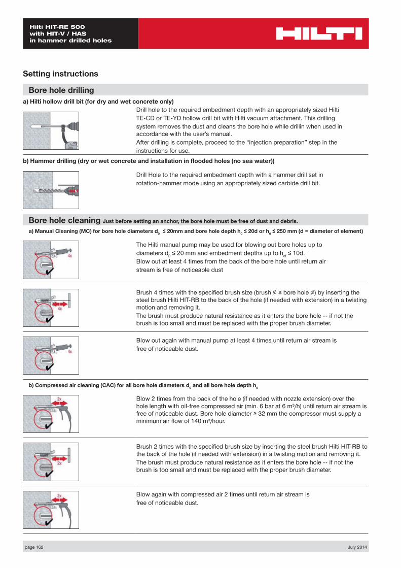
page 162 July 2014
Hilti HIT-RE 500 with HIT-V / HAS in hammer drilled holes
Setting instructions
Bore hole drillinga) Hilti hollow drill bit (for dry and wet concrete only)
Drill hole to the required embedment depth with an appropriately sized HiltiTE-CD or TE-YD hollow drill bit with Hilti vacuum attachment. This drillingsystem removes the dust and cleans the bore hole while drillin when used in accordance with the user’s manual.After drilling is complete, proceed to the “injection preparation” step in theinstructions for use.
b) Hammer drilling (dry or wet concrete and installation in flooded holes (no sea water))
Drill Hole to the required embedment depth with a hammer drill set inrotation-hammer mode using an appropriately sized carbide drill bit.
Bore hole cleaning Just before setting an anchor, the bore hole must be free of dust and debris.
a) Manual Cleaning (MC) for bore hole diameters d0 ≤ 20mm and bore hole depth h0 ≤ 20d or h0 ≤ 250 mm (d = diameter of element)
The Hilti manual pump may be used for blowing out bore holes up todiameters d0 ≤ 20 mm and embedment depths up to hef ≤ 10d.Blow out at least 4 times from the back of the bore hole until return airstream is free of noticeable dust
Brush 4 times with the specified brush size (brush ∅ ≥ bore hole ∅) by inserting the steel brush Hilti HIT-RB to the back of the hole (if needed with extension) in a twisting motion and removing it.The brush must produce natural resistance as it enters the bore hole -- if not the brush is too small and must be replaced with the proper brush diameter.
Blow out again with manual pump at least 4 times until return air stream isfree of noticeable dust.
b) Compressed air cleaning (CAC) for all bore hole diameters d0 and all bore hole depth h0
Blow 2 times from the back of the hole (if needed with nozzle extension) over the hole length with oil-free compressed air (min. 6 bar at 6 m³/h) until return air stream is free of noticeable dust. Bore hole diameter ≥ 32 mm the compressor must supply a minimum air flow of 140 m³/hour.
Brush 2 times with the specified brush size by inserting the steel brush Hilti HIT-RB to the back of the hole (if needed with extension) in a twisting motion and removing it.The brush must produce natural resistance as it enters the bore hole -- if not the brush is too small and must be replaced with the proper brush diameter.
Blow again with compressed air 2 times until return air stream isfree of noticeable dust.
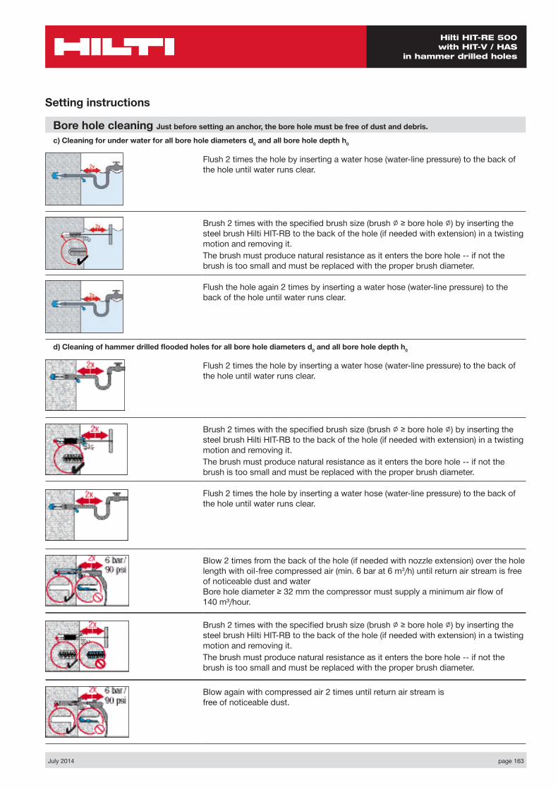
July 2014 page 163
Hilti HIT-RE 500 with HIT-V / HAS
in hammer drilled holes
Setting instructions
Bore hole cleaning Just before setting an anchor, the bore hole must be free of dust and debris.
c) Cleaning for under water for all bore hole diameters d0 and all bore hole depth h0
Flush 2 times the hole by inserting a water hose (water-line pressure) to the back of the hole until water runs clear.
Brush 2 times with the specified brush size (brush ∅ ≥ bore hole ∅) by inserting the steel brush Hilti HIT-RB to the back of the hole (if needed with extension) in a twisting motion and removing it.The brush must produce natural resistance as it enters the bore hole -- if not the brush is too small and must be replaced with the proper brush diameter.
Flush the hole again 2 times by inserting a water hose (water-line pressure) to the back of the hole until water runs clear.
d) Cleaning of hammer drilled flooded holes for all bore hole diameters d0 and all bore hole depth h0
Flush 2 times the hole by inserting a water hose (water-line pressure) to the back of the hole until water runs clear.
Brush 2 times with the specified brush size (brush ∅ ≥ bore hole ∅) by inserting the steel brush Hilti HIT-RB to the back of the hole (if needed with extension) in a twisting motion and removing it.The brush must produce natural resistance as it enters the bore hole -- if not the brush is too small and must be replaced with the proper brush diameter.
Flush 2 times the hole by inserting a water hose (water-line pressure) to the back of the hole until water runs clear.
Blow 2 times from the back of the hole (if needed with nozzle extension) over the hole length with oil-free compressed air (min. 6 bar at 6 m3/h) until return air stream is free of noticeable dust and water Bore hole diameter ≥ 32 mm the compressor must supply a minimum air flow of 140 m³/hour.
Brush 2 times with the specified brush size (brush ∅ ≥ bore hole ∅) by inserting the steel brush Hilti HIT-RB to the back of the hole (if needed with extension) in a twisting motion and removing it.The brush must produce natural resistance as it enters the bore hole -- if not the brush is too small and must be replaced with the proper brush diameter.
Blow again with compressed air 2 times until return air stream is free of noticeable dust.
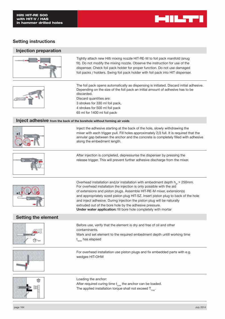
page 164 July 2014
Hilti HIT-RE 500 with HIT-V / HAS in hammer drilled holes
Injection preparationTightly attach new Hilti mixing nozzle HIT-RE-M to foil pack manifold (snugfit). Do not modify the mixing nozzle. Observe the instruction for use of thedispenser. Check foil pack holder for proper function. Do not use damagedfoil packs / holders. Swing foil pack holder with foil pack into HIT dispenser.
The foil pack opens automatically as dispensing is initiated. Discard initial adhesive. Depending on the size of the foil pack an initial amount of adhesive has to be discarded.Discard quantities are:3 strokes for 330 ml foil pack,4 strokes for 500 ml foil pack65 ml for 1400 ml foil pack
Inject adhesive from the back of the borehole without forming air voids
Inject the adhesive starting at the back of the hole, slowly withdrawing themixer with each trigger pull. Fill holes approximately 2/3 full. It is required that the annular gap between the anchor and the concrete is completely filled with adhesive along the embedment length.
After injection is completed, depressurise the dispenser by pressing therelease trigger. This will prevent further adhesive discharge from the mixer.
Overhead installation and/or installation with embedment depth hef > 250mm. For overhead installation the injection is only possible with the aidof extensions and piston plugs. Assemble HIT-RE-M mixer, extension(s)and appropriately sized piston plug HIT-SZ. Insert piston plug to back of the holeand inject adhesive. During injection the piston plug will be naturallyextruded out of the bore hole by the adhesive pressure. Under water application: fill bore hole completely with mortar
Setting the elementBefore use, verify that the element is dry and free of oil and othercontaminants.Mark and set element to the required embedment depth untill working timetwork has elapsed
For overhead installation use piston plugs and fix embedded parts with e.g.wedges HIT-OHW
Loading the anchor:After required curing time tcure the anchor can be loaded.The applied installation torque shall not exceed Tmax.
Setting instructions
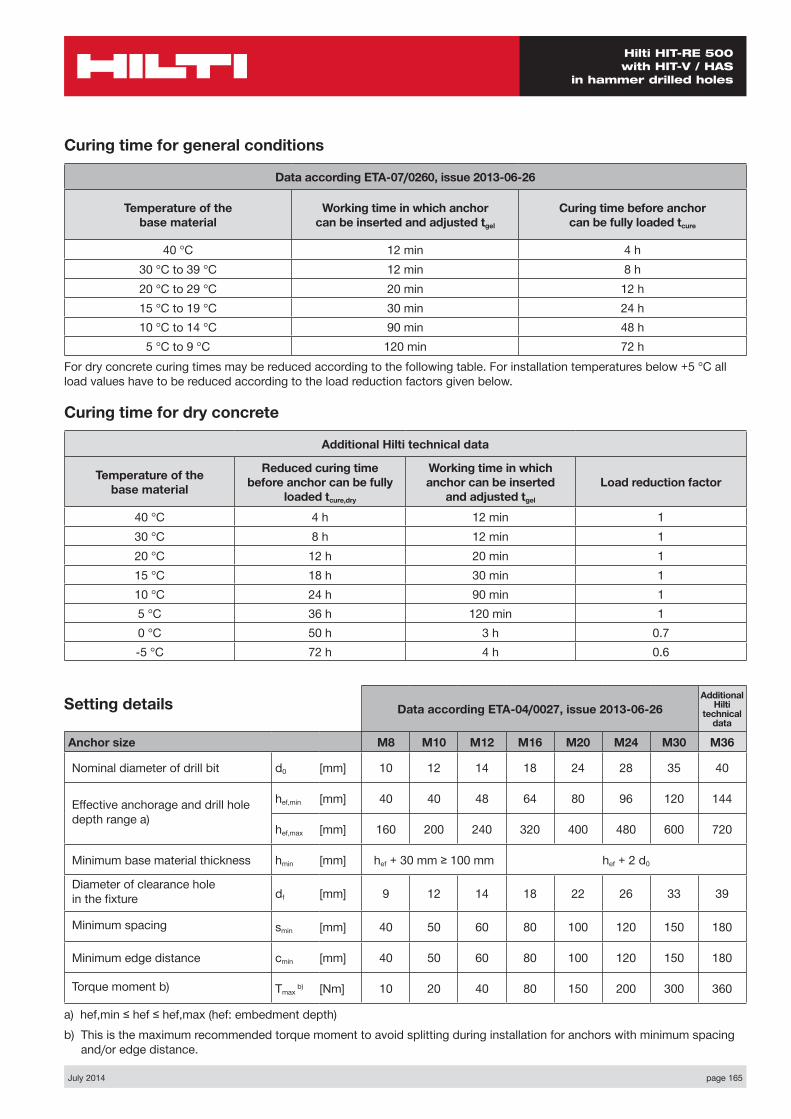
July 2014 page 165
Hilti HIT-RE 500 with HIT-V / HAS
in hammer drilled holes
Data according ETA-04/0027, issue 2013-06-26Additional
Hilti technical
data
Anchor size M8 M10 M12 M16 M20 M24 M30 M36
Nominal diameter of drill bit d0 [mm] 10 12 14 18 24 28 35 40
Effective anchorage and drill hole depth range a)
hef,min [mm] 40 40 48 64 80 96 120 144
hef,max [mm] 160 200 240 320 400 480 600 720
Minimum base material thickness hmin [mm] hef + 30 mm ≥ 100 mm hef + 2 d0
Diameter of clearance hole in the fixture df [mm] 9 12 14 18 22 26 33 39
Minimum spacing smin [mm] 40 50 60 80 100 120 150 180
Minimum edge distance cmin [mm] 40 50 60 80 100 120 150 180
Torque moment b) Tmax b) [Nm] 10 20 40 80 150 200 300 360
a) hef,min ≤ hef ≤ hef,max (hef: embedment depth)b) This is the maximum recommended torque moment to avoid splitting during installation for anchors with minimum spacing
and/or edge distance.
Setting details
Curing time for general conditions
Data according ETA-07/0260, issue 2013-06-26
Temperature of the base material
Working time in which anchor can be inserted and adjusted tgel
Curing time before anchor can be fully loaded tcure
40 °C 12 min 4 h30 °C to 39 °C 12 min 8 h20 °C to 29 °C 20 min 12 h15 °C to 19 °C 30 min 24 h10 °C to 14 °C 90 min 48 h5 °C to 9 °C 120 min 72 h
For dry concrete curing times may be reduced according to the following table. For installation temperatures below +5 °C all load values have to be reduced according to the load reduction factors given below.
Curing time for dry concrete
Additional Hilti technical data
Temperature of the base material
Reduced curing time before anchor can be fully
loaded tcure,dry
Working time in which anchor can be inserted
and adjusted tgel
Load reduction factor
40 °C 4 h 12 min 130 °C 8 h 12 min 120 °C 12 h 20 min 115 °C 18 h 30 min 110 °C 24 h 90 min 15 °C 36 h 120 min 10 °C 50 h 3 h 0.7-5 °C 72 h 4 h 0.6
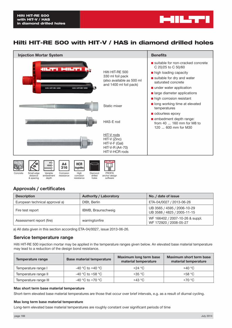
page 166 July 2014
Hilti HIT-RE 500 with HIT-V / HAS in diamond drilled holes
Diamond drilled holes
Small edge distance
& spacing
Concrete
A4 316
Corrosion resistance
HCR highMo
High corrosion resistance
Hilti HIT-RE 500 with HIT-V / HAS in diamond drilled holes
Injection Mortar System
Variable embedment
depth
Hilti HIT-RE 500330 ml foil pack(also available as 500 mland 1400 ml foil pack)
Approvals / certificatesDescription Authority / Laboratory No. / date of issueEuropean technical approval a) DIBt, Berlin ETA-04/0027 / 2013-06-26
Fire test report IBMB, Braunschweig UB 3565 / 4595 / 2006-10-29 UB 3588 / 4825 / 2005-11-15
Assessment report (fire) warringtonfire WF 166402 / 2007-10-26 & suppl. WF 172920 / 2008-05-27
a) All data given in this section according ETA-04/0027, issue 2013-06-26.
Service temperature rangeHilti HIT-RE 500 injection mortar may be applied in the temperature ranges given below. An elevated base material temperature may lead to a reduction of the design bond resistance.
Temperature range Base material temperature Maximum long term base material temperature
Maximum short term base material temperature
Temperature range I -40 °C to +40 °C +24 °C +40 °CTemperature range II -40 °C to +58 °C +35 °C +58 °CTemperature range III -40 °C to +70 °C +43 °C +70 °C
Max short term base material temperatureShort-term elevated base material temperatures are those that occur over brief intervals, e.g. as a result of diurnal cycling.
Max long term base material temperatureLong-term elevated base material temperatures are roughly constant over significant periods of time
Benefits
■ suitable for non-cracked concrete C 20/25 to C 50/60
■ high loading capacity■ suitable for dry and water
saturated concrete■ under water application■ large diameter applications■ high corrosion resistant■ long working time at elevated
temperatures■ odourless epoxy■ embedment depth range:
from 40 … 160 mm for M8 to 120 … 600 mm for M30
PROFIS anchor design
software
Static mixer
HAS-E rod
HIT-V rodsHIT-V (Zinc)HIT-V-F (Gal)HIT-V-R (A4-70)HIT-V-HCR rods
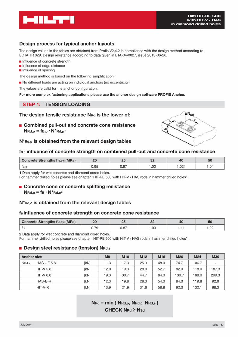
July 2014 page 167
Hilti HIT-RE 500 with HIT-V / HAS
in diamond drilled holes
Design process for typical anchor layoutsThe design values in the tables are obtained from Profis V2.4.2 in compliance with the design method according to EOTA TR 029. Design resistance according to data given in ETA-04/0027, issue 2013-06-26.■ Influence of concrete strength ■ Influence of edge distance ■ Influence of spacingThe design method is based on the following simplification:■ No different loads are acting on individual anchors (no eccentricity)The values are valid for the anchor configuration.For more complex fastening applications please use the anchor design software PROFIS Anchor.
STEP 1: TENSION LOADING
The design tensile resistance NRd is the lower of:
■ Combined pull-out and concrete cone resistance NRd,p = fB,p • N*Rd,p 1
N*Rd,p is obtained from the relevant design tables
fB,p influence of concrete strength on combined pull-out and concrete cone resistance
Concrete Strengths f’c,cyl (MPa) 20 25 32 40 50fB,p 0.95 0.97 1.00 1.021 1.04
1 Data apply for wet concrete and diamond cored holes. For hammer drilled holes please see chapter “HIT-RE 500 with HIT-V / HAS rods in hammer drilled holes”.
■ Concrete cone or concrete splitting resistance NRd,c = fB • N*Rd,c 2
N*Rd,c is obtained from the relevant design tables
fB influence of concrete strength on concrete cone resistance
Concrete Strengths f’c,cyl (MPa) 20 25 32 40 50fB 0.79 0.87 1.00 1.11 1.22
2 Data apply for wet concrete and diamond cored holes. For hammer drilled holes please see chapter “HIT-RE 500 with HIT-V / HAS rods in hammer drilled holes”.
■ Design steel resistance (tension) NRd,s
Anchor size M8 M10 M12 M16 M20 M24 M30NRd,s HAS – E 5.8 [kN] 11.3 17.3 25.3 48.0 74.7 106.7 -
HIT-V 5.8 [kN] 12.0 19.3 28.0 52.7 82.0 118.0 187.3HIT-V 8.8 [kN] 19.3 30.7 44.7 84.0 130.7 188.0 299.3HAS-E-R [kN] 12.3 19.8 28.3 54.0 84.0 119.8 92.0HIT-V-R [kN] 13.9 21.9 31.6 58.8 92.0 132.1 98.3
NRd = min { NRd,p, NRd,c, NRd,s } CHECK NRd ≥ NSd

page 168 July 2014
Hilti HIT-RE 500 with HIT-V / HAS in diamond drilled holes
STEP 2: SHEAR LOADING
The design shear resistance VRd is the lower of:
■ Design Concrete Edge Resistance VRd,c = fB • V*Rd,c
V*Rd,c is obtained from the relevant design table
fB influence of concrete strength
Concrete Strengths f’c,cyl (MPa) 20 25 32 40 50fB 0.79 0.87 1.00 1.11 1.22
Shear load acting parallel to edge:These tables are for a single free edge only2 anchors:For shear loads acting parallel to this edge, the concrete resistance V*Rd,c can be multiplied by the factor = 2.54 anchors:For shear loads acting parallel to the edge - the anchor row closest to the edge is checked to resist half the total design load. To obtain the concrete resistance use the corresponding 2 anchor configuration V*Rd,c and multiply by the factor = 2.5
■ Design steel resistance (shear): VRd,s
Anchor size M8 M10 M12 M16 M20 M24 M30VRd,s HAS – E 5.8 [kN] 6.8 10.4 15.2 28.8 44.8 64.0 -
HIT-V 5.8 [kN] 7.2 12.0 16.8 31.2 48.8 70.4 112.0HIT-V 8.8 [kN] 12.0 18.4 27.2 50.4 78.4 112.8 179.2HAS-E-R [kN] 7.7 12,2 17.3 32.7 50.6 71.8 55.5HIT-V-R [kN] 8.3 12.8 19.2 35.3 55.1 79.5 58.8
STEP 3: COMBINED TENSION AND SHEAR LOADING
The following equations must be satisfied:
NSd/NRd + VSd/VRd ≤ 1.2
and
NSd/NRd ≤ 1, VSd/VRd ≤ 1
VRd = min { VRd,c, VRd,s } CHECK VRd ≥ VSd
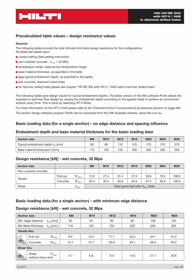
July 2014 page 169
Hilti HIT-RE 500 with HIT-V / HAS
in diamond drilled holes
Basic loading data (for a single anchor) – no edge distance and spacing influence
Embedment depth and base material thickness for the basic loading data
Anchor size M8 M10 M12 M16 M20 M24 M30
Typical embedment depth hef [mm] 80 90 110 125 170 210 270
Base material thickness h [mm] 110 120 150 200 250 300 350
Precalculated table values – design resistance values
General:The following tables provide the total ultimate limit state design resistance for the configurations. All tables are based upon:■ correct setting (See setting instruction)■ non-cracked concrete – fc,cyl = 32 MPa■ temperature range I (see service temperature range)■ base material thickness, as specified in the table■ One typical embedment depth, as specified in the tables■ wet concrete, diamond cored holes■ for hammer drilled holes please see chapter “HIT-RE 500 with HIT-V / HAS rods in hammer drilled holes”
The following tables give design values for typical embedment depths. The latest version of the Hilti software Profis allows the engineer to optimise their design by varying the embedment depth according to the applied loads to achieve an economical solution every time. This is done by selecting HIT-V-Rods.For more information on the HIT V rods please refer to the Chemical Anchor Components & Accessories section on page 266.The anchor design software program Profis can be download from the Hilti Australia website, www.hilti.com.au.
Design resistance [kN] - wet concrete, 32 Mpa
Anchor size M8 M10 M12 M16 M20 M24 M30Non-cracked concrete
Tensile Pull-out N*Rd,p 15.2 21.4 31.4 37.6 58.6 79.0 108.0Concrete N*Rd,c 25.4 30.3 40.9 42.5 67.4 92.6 135.0
Shear VRd,s Steel governed refer VRd,s table
Basic loading data (for a single anchor) – with minimum edge distance
Design resistance [kN] - wet concrete, 32 Mpa
Anchor size M8 M10 M12 M16 M20 M24Min. edge distance cmin [mm] 40 50 60 80 100 120Min Base thickness hmin [mm] 110 120 150 200 250 300
Tensile NRd
Pull-out N*Rd,p 8.5 12.0 17.7 22.2 34.1 47.0
Concrete N*Rd,c 12.1 14.7 20.9 25.1 38.0 50.4
Shear VRd
Shear V*Rd,c (without lever arm) 4.7 6.8 9.3 14.5 21.7 29.8
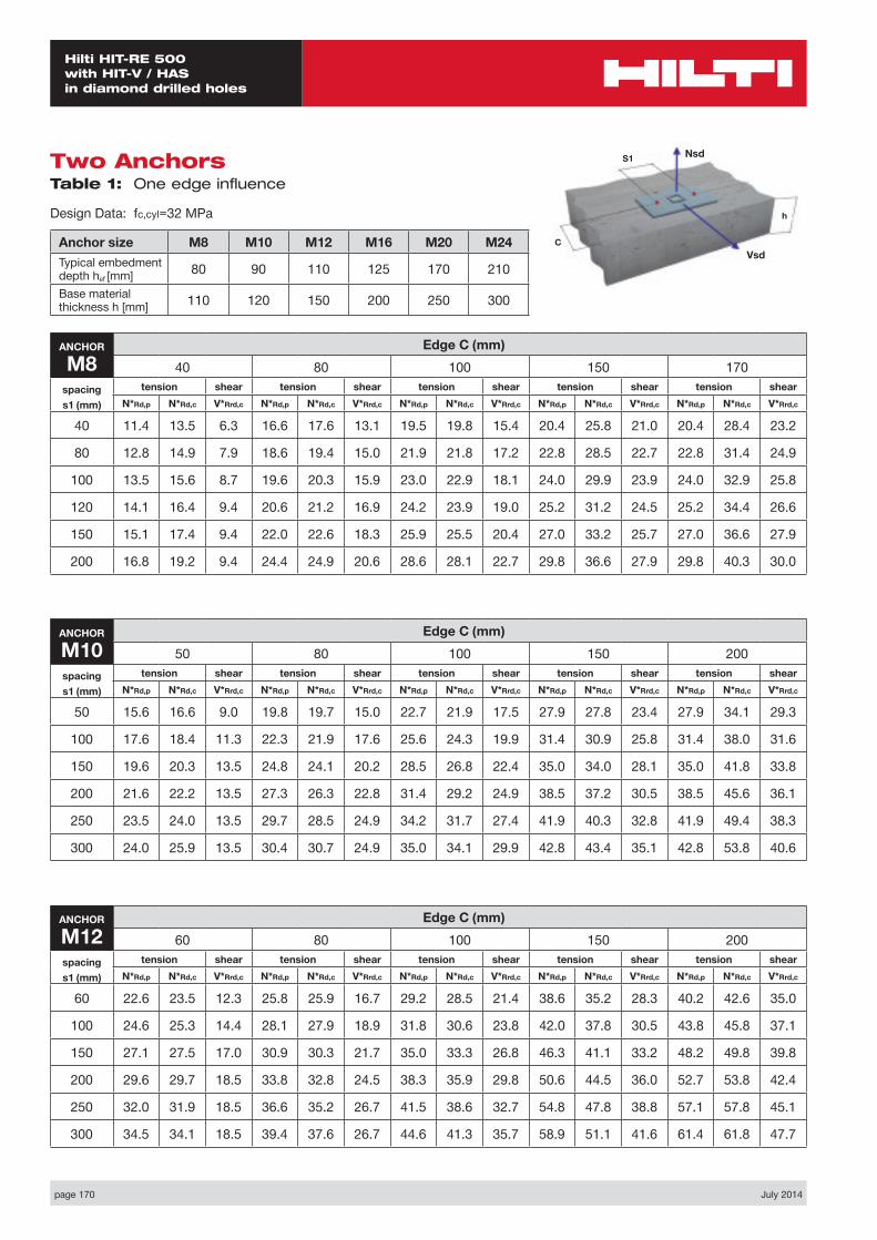
page 170 July 2014
Hilti HIT-RE 500 with HIT-V / HAS in diamond drilled holes
Nsd
Vsd
S1
C
h
Two Anchors Table 1: One edge influence
Design Data: fc,cyl=32 MPa
Anchor size M8 M10 M12 M16 M20 M24Typical embedment depth hef [mm] 80 90 110 125 170 210
Base material thickness h [mm] 110 120 150 200 250 300
ANCHOR
M8Edge C (mm)
40 80 100 150 170spacings1 (mm)
tension shear tension shear tension shear tension shear tension shearN*Rd,p N*Rd,c V*Rrd,c N*Rd,p N*Rd,c V*Rrd,c N*Rd,p N*Rd,c V*Rrd,c N*Rd,p N*Rd,c V*Rrd,c N*Rd,p N*Rd,c V*Rrd,c
40 11.4 13.5 6.3 16.6 17.6 13.1 19.5 19.8 15.4 20.4 25.8 21.0 20.4 28.4 23.2
80 12.8 14.9 7.9 18.6 19.4 15.0 21.9 21.8 17.2 22.8 28.5 22.7 22.8 31.4 24.9
100 13.5 15.6 8.7 19.6 20.3 15.9 23.0 22.9 18.1 24.0 29.9 23.9 24.0 32.9 25.8
120 14.1 16.4 9.4 20.6 21.2 16.9 24.2 23.9 19.0 25.2 31.2 24.5 25.2 34.4 26.6
150 15.1 17.4 9.4 22.0 22.6 18.3 25.9 25.5 20.4 27.0 33.2 25.7 27.0 36.6 27.9
200 16.8 19.2 9.4 24.4 24.9 20.6 28.6 28.1 22.7 29.8 36.6 27.9 29.8 40.3 30.0
ANCHOR
M10Edge C (mm)
50 80 100 150 200spacings1 (mm)
tension shear tension shear tension shear tension shear tension shearN*Rd,p N*Rd,c V*Rrd,c N*Rd,p N*Rd,c V*Rrd,c N*Rd,p N*Rd,c V*Rrd,c N*Rd,p N*Rd,c V*Rrd,c N*Rd,p N*Rd,c V*Rrd,c
50 15.6 16.6 9.0 19.8 19.7 15.0 22.7 21.9 17.5 27.9 27.8 23.4 27.9 34.1 29.3
100 17.6 18.4 11.3 22.3 21.9 17.6 25.6 24.3 19.9 31.4 30.9 25.8 31.4 38.0 31.6
150 19.6 20.3 13.5 24.8 24.1 20.2 28.5 26.8 22.4 35.0 34.0 28.1 35.0 41.8 33.8
200 21.6 22.2 13.5 27.3 26.3 22.8 31.4 29.2 24.9 38.5 37.2 30.5 38.5 45.6 36.1
250 23.5 24.0 13.5 29.7 28.5 24.9 34.2 31.7 27.4 41.9 40.3 32.8 41.9 49.4 38.3
300 24.0 25.9 13.5 30.4 30.7 24.9 35.0 34.1 29.9 42.8 43.4 35.1 42.8 53.8 40.6
ANCHOR
M12Edge C (mm)
60 80 100 150 200spacings1 (mm)
tension shear tension shear tension shear tension shear tension shearN*Rd,p N*Rd,c V*Rrd,c N*Rd,p N*Rd,c V*Rrd,c N*Rd,p N*Rd,c V*Rrd,c N*Rd,p N*Rd,c V*Rrd,c N*Rd,p N*Rd,c V*Rrd,c
60 22.6 23.5 12.3 25.8 25.9 16.7 29.2 28.5 21.4 38.6 35.2 28.3 40.2 42.6 35.0
100 24.6 25.3 14.4 28.1 27.9 18.9 31.8 30.6 23.8 42.0 37.8 30.5 43.8 45.8 37.1
150 27.1 27.5 17.0 30.9 30.3 21.7 35.0 33.3 26.8 46.3 41.1 33.2 48.2 49.8 39.8
200 29.6 29.7 18.5 33.8 32.8 24.5 38.3 35.9 29.8 50.6 44.5 36.0 52.7 53.8 42.4
250 32.0 31.9 18.5 36.6 35.2 26.7 41.5 38.6 32.7 54.8 47.8 38.8 57.1 57.8 45.1
300 34.5 34.1 18.5 39.4 37.6 26.7 44.6 41.3 35.7 58.9 51.1 41.6 61.4 61.8 47.7
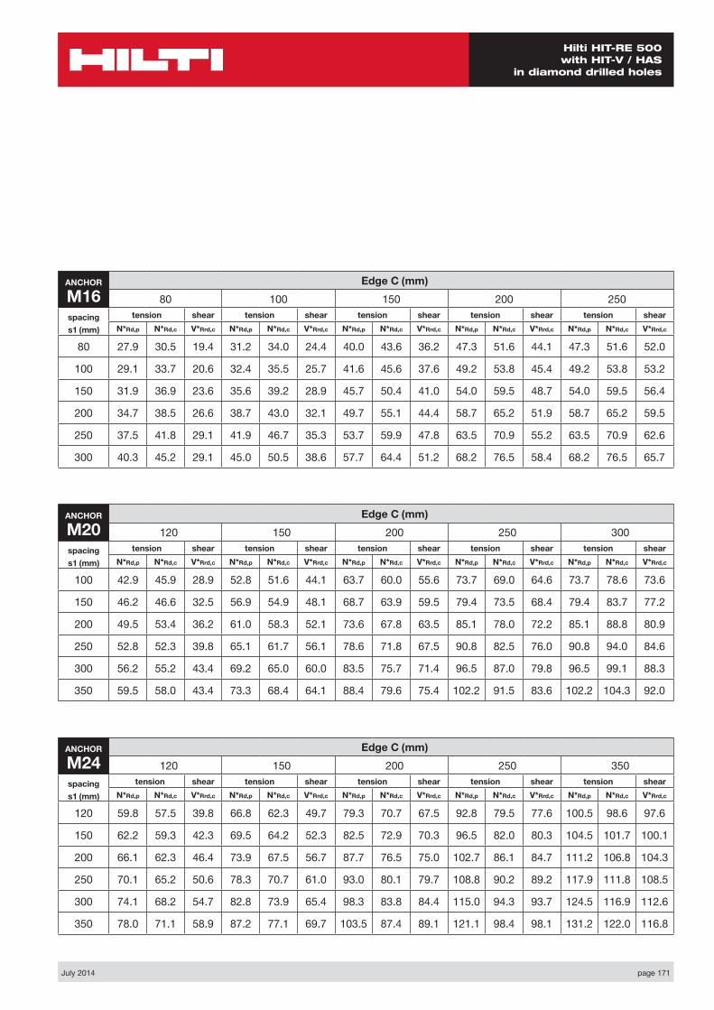
July 2014 page 171
Hilti HIT-RE 500 with HIT-V / HAS
in diamond drilled holes
ANCHOR
M24Edge C (mm)
120 150 200 250 350spacings1 (mm)
tension shear tension shear tension shear tension shear tension shearN*Rd,p N*Rd,c V*Rrd,c N*Rd,p N*Rd,c V*Rrd,c N*Rd,p N*Rd,c V*Rrd,c N*Rd,p N*Rd,c V*Rrd,c N*Rd,p N*Rd,c V*Rrd,c
120 59.8 57.5 39.8 66.8 62.3 49.7 79.3 70.7 67.5 92.8 79.5 77.6 100.5 98.6 97.6
150 62.2 59.3 42.3 69.5 64.2 52.3 82.5 72.9 70.3 96.5 82.0 80.3 104.5 101.7 100.1
200 66.1 62.3 46.4 73.9 67.5 56.7 87.7 76.5 75.0 102.7 86.1 84.7 111.2 106.8 104.3
250 70.1 65.2 50.6 78.3 70.7 61.0 93.0 80.1 79.7 108.8 90.2 89.2 117.9 111.8 108.5
300 74.1 68.2 54.7 82.8 73.9 65.4 98.3 83.8 84.4 115.0 94.3 93.7 124.5 116.9 112.6
350 78.0 71.1 58.9 87.2 77.1 69.7 103.5 87.4 89.1 121.1 98.4 98.1 131.2 122.0 116.8
ANCHOR
M16Edge C (mm)
80 100 150 200 250spacings1 (mm)
tension shear tension shear tension shear tension shear tension shearN*Rd,p N*Rd,c V*Rrd,c N*Rd,p N*Rd,c V*Rrd,c N*Rd,p N*Rd,c V*Rrd,c N*Rd,p N*Rd,c V*Rrd,c N*Rd,p N*Rd,c V*Rrd,c
80 27.9 30.5 19.4 31.2 34.0 24.4 40.0 43.6 36.2 47.3 51.6 44.1 47.3 51.6 52.0
100 29.1 33.7 20.6 32.4 35.5 25.7 41.6 45.6 37.6 49.2 53.8 45.4 49.2 53.8 53.2
150 31.9 36.9 23.6 35.6 39.2 28.9 45.7 50.4 41.0 54.0 59.5 48.7 54.0 59.5 56.4
200 34.7 38.5 26.6 38.7 43.0 32.1 49.7 55.1 44.4 58.7 65.2 51.9 58.7 65.2 59.5
250 37.5 41.8 29.1 41.9 46.7 35.3 53.7 59.9 47.8 63.5 70.9 55.2 63.5 70.9 62.6
300 40.3 45.2 29.1 45.0 50.5 38.6 57.7 64.4 51.2 68.2 76.5 58.4 68.2 76.5 65.7
ANCHOR
M20Edge C (mm)
120 150 200 250 300spacings1 (mm)
tension shear tension shear tension shear tension shear tension shearN*Rd,p N*Rd,c V*Rrd,c N*Rd,p N*Rd,c V*Rrd,c N*Rd,p N*Rd,c V*Rrd,c N*Rd,p N*Rd,c V*Rrd,c N*Rd,p N*Rd,c V*Rrd,c
100 42.9 45.9 28.9 52.8 51.6 44.1 63.7 60.0 55.6 73.7 69.0 64.6 73.7 78.6 73.6
150 46.2 46.6 32.5 56.9 54.9 48.1 68.7 63.9 59.5 79.4 73.5 68.4 79.4 83.7 77.2
200 49.5 53.4 36.2 61.0 58.3 52.1 73.6 67.8 63.5 85.1 78.0 72.2 85.1 88.8 80.9
250 52.8 52.3 39.8 65.1 61.7 56.1 78.6 71.8 67.5 90.8 82.5 76.0 90.8 94.0 84.6
300 56.2 55.2 43.4 69.2 65.0 60.0 83.5 75.7 71.4 96.5 87.0 79.8 96.5 99.1 88.3
350 59.5 58.0 43.4 73.3 68.4 64.1 88.4 79.6 75.4 102.2 91.5 83.6 102.2 104.3 92.0

page 172 July 2014
Hilti HIT-RE 500 with HIT-V / HAS in diamond drilled holes
Four anchors Table 2: One edge influence
Design Data: fc,cyl=32 MPa
Anchor size M8 M10 M12 M16 M20 M24Typical embedment depth hef [mm] 80 90 110 125 170 210
Base material thickness h [mm] 110 120 150 200 250 300
ANCHOR
M8Edge C (mm)
40 80 100 150 200spacing
s1=s2 (mm)
tension shear tension shear tension shear tension shear tension shearN*Rd,p N*Rd,c V*Rrd,c N*Rd,p N*Rd,c V*Rrd,c N*Rd,p N*Rd,c V*Rrd,c N*Rd,p N*Rd,c V*Rrd,c N*Rd,p N*Rd,c V*Rrd,c
40 16.9 16.1 12.6 23.4 20.4 17.7 27.0 22.7 19.9 28.0 29.0 25.4 28.0 31.7 30.9
80 22.0 20.6 15.8 29.6 25.6 23.8 33.7 28.3 26.0 34.9 35.6 31.5 34.9 38.7 36.8
100 24.8 23.1 17.4 32.9 28.5 26.9 37.4 31.3 29.0 38.6 39.2 34.4 38.6 42.5 39.8
120 27.7 25.7 18.8 36.3 31.4 29.9 41.1 34.5 32.0 42.4 42.9 37.4 42.4 46.5 42.7
150 32.2 29.9 18.8 41.7 36.2 34.3 46.9 39.6 36.4 48.3 48.8 41.8 48.3 52.7 47.0
200 40.1 37.5 18.8 51.0 44.9 41.2 57.0 48.9 43.7 58.6 59.5 49.0 58.6 64.1 54.2
ANCHOR
M10Edge C (mm)
50 80 100 150 200spacing
s1=s2 (mm)
tension shear tension shear tension shear tension shear tension shearN*Rd,p N*Rd,c V*Rrd,c N*Rd,p N*Rd,c V*Rrd,c N*Rd,p N*Rd,c V*Rrd,c N*Rd,p N*Rd,c V*Rrd,c N*Rd,p N*Rd,c V*Rrd,c
50 22.4 19.9 17.5 27.4 23.2 21.0 31.0 25.5 23.4 37.2 31.8 29.3 37.2 38.4 35.1
100 29.7 25.9 22.6 35.6 29.8 29.2 39.8 32.5 31.6 47.0 39.8 37.3 47.0 47.5 43.0
150 37.8 32.6 27.0 44.7 37.1 37.2 49.6 40.2 39.5 57.9 48.7 45.1 57.9 57.6 50.8
200 46.7 40.0 27.0 54.6 45.2 45.0 60.2 48.8 47.3 69.7 58.5 52.8 69.7 68.6 58.4
250 56.2 48.2 27.0 65.2 54.1 49.8 71.5 58.2 54.8 82.2 69.2 60.5 82.2 80.6 66.0
300 58.9 57.2 27.0 68.1 63.8 49.8 74.7 68.5 59.8 85.6 80.8 68.1 85.6 93.6 73.6
ANCHOR
M12Edge C (mm)
60 80 100 150 200spacing
s1=s2 (mm)
tension shear tension shear tension shear tension shear tension shearN*Rd,p N*Rd,c V*Rrd,c N*Rd,p N*Rd,c V*Rrd,c N*Rd,p N*Rd,c V*Rrd,c N*Rd,p N*Rd,c V*Rrd,c N*Rd,p N*Rd,c V*Rrd,c
60 31.6 28.3 24.2 35.5 30.9 26.9 39.6 33.5 29.6 50.7 40.7 36.3 52.6 48.5 42.9
100 38.6 33.8 28.8 43.0 36.7 34.5 47.6 39.7 37.1 60.0 47.6 43.7 62.1 56.3 50.2
150 48.3 41.4 34.0 53.3 44.7 43.4 58.6 48.1 46.2 72.7 57.1 52.7 75.1 66.9 59.1
200 58.8 49.8 37.0 64.5 53.5 49.0 70.5 57.3 55.2 86.5 67.5 61.6 89.2 78.5 67.9
250 70.2 58.9 37.0 76.6 63.0 53.4 83.3 67.3 64.0 101.3 78.7 70.3 104.3 90.9 76.6
300 82.3 68.7 37.0 89.5 73.4 53.4 97.0 78.1 71.4 116.9 90.8 79.0 120.3 104.3 85.3
Nsd
Vsd
S2
S1
C
h

July 2014 page 173
Hilti HIT-RE 500 with HIT-V / HAS
in diamond drilled holes
ANCHOR
M24Edge C (mm)
120 150 200 250 350spacing
s1=s2 (mm)
tension shear tension shear tension shear tension shear tension shearN*Rd,p N*Rd,c V*Rrd,c N*Rd,p N*Rd,c V*Rrd,c N*Rd,p N*Rd,c V*Rrd,c N*Rd,p N*Rd,c V*Rrd,c N*Rd,p N*Rd,c V*Rrd,c
120 82.6 70.2 75.6 90.8 75.3 81.6 105.4 84.2 91.6 120.9 93.7 101.6 129.8 113.9 121.2
150 90.4 75.6 84.3 99.1 80.1 90.2 114.4 90.3 100.1 130.8 100.2 110.0 140.2 121.3 129.4
200 104.1 85.1 92.8 113.6 90.9 104.3 130.3 101.0 114.0 148.2 111.5 123.7 158.4 134.3 143.0
250 118.6 95.1 101.2 129.0 101.3 118.1 147.2 112.2 127.7 166.6 123.5 137.3 177.6 147.9 156.3
300 134.1 105.6 109.4 145.3 112.3 130.8 165.0 123.9 141.2 186.0 136.1 150.7 197.9 162.1 169.5
350 150.3 116.7 117.8 162.5 123.9 139.4 183.8 136.3 154.5 206.4 149.3 163.9 219.2 177.0 182.6
ANCHOR
M16Edge C (mm)
80 100 150 200 250spacing
s1=s2 (mm)
tension shear tension shear tension shear tension shear tension shearN*Rd,p N*Rd,c V*Rrd,c N*Rd,p N*Rd,c V*Rrd,c N*Rd,p N*Rd,c V*Rrd,c N*Rd,p N*Rd,c V*Rrd,c N*Rd,p N*Rd,c V*Rrd,c
80 38.1 39.6 37.8 41.8 43.5 41.0 51.9 54.0 48.8 60.2 62.6 56.6 60.2 62.6 64.3
100 41.7 43.7 41.2 45.7 47.9 45.4 56.4 59.1 53.2 65.1 68.2 60.9 65.1 74.6 68.6
150 51.4 54.9 46.2 56.0 59.7 56.3 68.2 72.2 64.6 78.1 83.3 71.6 78.1 83.3 79.1
200 62.2 67.2 53.2 67.3 72.4 64.2 81.1 86.0 74.6 92.3 99.9 82.1 92.3 99.9 89.5
250 73.8 79.9 58.2 79.6 85.7 70.6 95.1 101.0 85.0 107.6 117.6 92.4 107.6 118.1 99.8
300 86.3 93.7 58.2 92.8 101.0 77.2 110.1 117.3 95.3 124.0 135.8 102.6 124.0 137.7 110.0
ANCHOR
M20Edge C (mm)
100 150 200 250 300spacing
s1=s2 (mm)
tension shear tension shear tension shear tension shear tension shearN*Rd,p N*Rd,c V*Rrd,c N*Rd,p N*Rd,c V*Rrd,c N*Rd,p N*Rd,c V*Rrd,c N*Rd,p N*Rd,c V*Rrd,c N*Rd,p N*Rd,c V*Rrd,c
100 58.5 53.8 55.6 70.0 62.2 64.6 82.5 71.2 73.6 93.9 80.8 82.4 93.9 91.0 91.2
150 69.5 62.7 65.0 82.3 72.0 77.2 96.2 81.9 86.0 108.8 92.4 94.8 108.8 103.6 103.4
200 81.4 72.3 72.4 95.6 82.5 89.6 110.9 93.3 98.3 124.7 104.8 106.9 124.7 117.0 115.5
250 94.2 82.5 79.6 109.8 93.7 101.8 126.6 105.5 110.3 141.7 118.0 118.9 141.8 131.2 127.3
300 107.8 93.4 86.8 124.9 105.5 113.8 143.3 118.3 122.3 159.8 131.9 130.7 159.8 146.2 139.1
350 122.2 105.0 86.8 140.9 118.1 125.6 160.9 132.0 134.1 178.8 146.6 142.4 178.8 162.0 150.8
Shear design: The concrete edge resistance value in this table uses all 4 anchors in shear. You will need to ensure the gap between anchor and the plate is filled. This can be achieved using the Hilti Dynamic Set. (Refer page 41 for further details)
The concrete edge resistance values have been obtained by taking the lesser of:1. First row resistance multiplied by number of rows and 2. The concrete edge resistance of the furthest row.

page 174 July 2014
Hilti HIT-RE 500 with HIT-V / HAS in diamond drilled holes
MaterialsMechanical properties of HIT-V / HAS
Data according ETA-04/0027, issue 2013-06-26 Additional Hilti technical data
Anchor size M8 M10 M12 M16 M20 M24 M30 M36
Nominal tensile strength fuk
HIT-V/HAS 5.8 [N/mm²] 500 500 500 500 500 500 500 500HIT-V/HAS 8.8 [N/mm²] 800 800 800 800 800 800 800 800HIT-V/HAS -R [N/mm²] 700 700 700 700 700 700 500 500HIT-V/HAS -HCR [N/mm²] 800 800 800 800 800 700 700 500
Yield strength fyk
HIT-V/HAS 5.8 [N/mm²] 400 400 400 400 400 400 400 400HIT-V/HAS 8.8 [N/mm²] 640 640 640 640 640 640 640 640HIT-V/HAS -R [N/mm²] 450 450 450 450 450 450 210 210
HIT-V/HAS -HCR [N/mm²] 600 600 600 600 600 400 400 250Stressed cross- section As
HAS [mm²] 32.8 52.3 76.2 144 225 324 519 759
HIT-V [mm²] 36.6 58.0 84.3 157 245 353 561 817Section Modulus Z
HAS [mm³] 27.0 54.1 93.8 244 474 809 1706 2949
HIT-V [mm³] 31.2 62.3 109 277 541 935 1874 3294
Steel failure with lever arm M8 M10 M12 M16 M20 M24 M30 M36
Design bending moment MRd,s
HIT-V-5.8 [Nm] 15 30 53 134 260 449 900 1581
HIT-V-8.8 [Nm] 24 48 84 213 415 718 1439 2530
HIT-V-R [Nm] 17 33 59 149 291 504 472 830
HIT-V-HCR [Nm] 24 48 84 213 416 449 899 1129
HAS-E-5.8 [Nm] 13 26 45 118 227 389 NA NA
HAS-E-8.8 [Nm] NA NA NA NA NA NA 1310 2265
HAS-E-R [Nm] 15 29 51 131 255 436 430 743
HAS-E-HCR [Nm] 21 42 72 187 364 389 819 1011
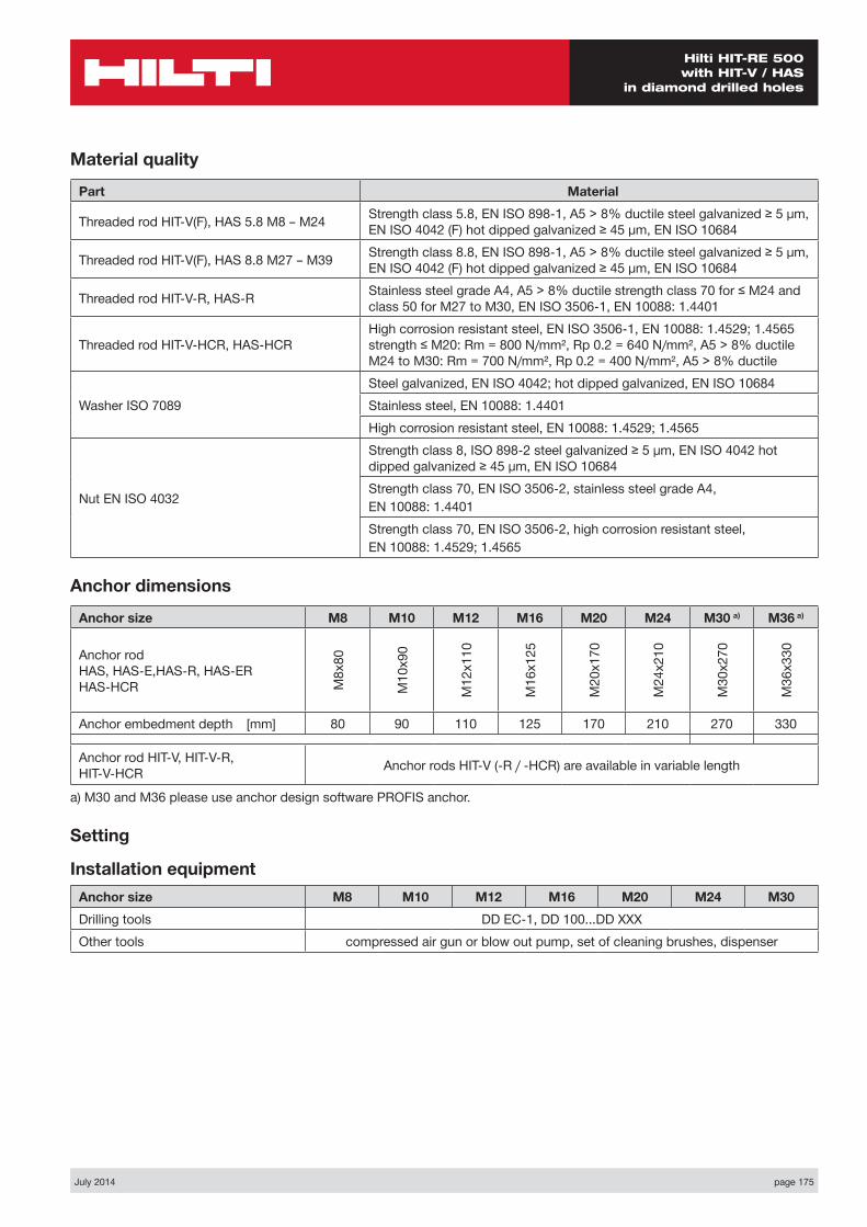
July 2014 page 175
Hilti HIT-RE 500 with HIT-V / HAS
in diamond drilled holes
Material quality
Part Material
Threaded rod HIT-V(F), HAS 5.8 M8 – M24 Strength class 5.8, EN ISO 898-1, A5 > 8% ductile steel galvanized ≥ 5 µm, EN ISO 4042 (F) hot dipped galvanized ≥ 45 µm, EN ISO 10684
Threaded rod HIT-V(F), HAS 8.8 M27 – M39 Strength class 8.8, EN ISO 898-1, A5 > 8% ductile steel galvanized ≥ 5 µm, EN ISO 4042 (F) hot dipped galvanized ≥ 45 µm, EN ISO 10684
Threaded rod HIT-V-R, HAS-R Stainless steel grade A4, A5 > 8% ductile strength class 70 for ≤ M24 and class 50 for M27 to M30, EN ISO 3506-1, EN 10088: 1.4401
Threaded rod HIT-V-HCR, HAS-HCRHigh corrosion resistant steel, EN ISO 3506-1, EN 10088: 1.4529; 1.4565 strength ≤ M20: Rm = 800 N/mm², Rp 0.2 = 640 N/mm², A5 > 8% ductile M24 to M30: Rm = 700 N/mm², Rp 0.2 = 400 N/mm², A5 > 8% ductile
Washer ISO 7089Steel galvanized, EN ISO 4042; hot dipped galvanized, EN ISO 10684Stainless steel, EN 10088: 1.4401High corrosion resistant steel, EN 10088: 1.4529; 1.4565
Nut EN ISO 4032
Strength class 8, ISO 898-2 steel galvanized ≥ 5 µm, EN ISO 4042 hot dipped galvanized ≥ 45 µm, EN ISO 10684Strength class 70, EN ISO 3506-2, stainless steel grade A4,EN 10088: 1.4401Strength class 70, EN ISO 3506-2, high corrosion resistant steel,EN 10088: 1.4529; 1.4565
Anchor dimensions
Anchor size M8 M10 M12 M16 M20 M24 M30 a) M36 a)
Anchor rod HAS, HAS-E,HAS-R, HAS-ER HAS-HCR M
8x80
M10
x90
M12
x110
M16
x125
M20
x170
M24
x210
M30
x270
M36
x330
Anchor embedment depth [mm] 80 90 110 125 170 210 270 330
Anchor rod HIT-V, HIT-V-R, HIT-V-HCR Anchor rods HIT-V (-R / -HCR) are available in variable length
a) M30 and M36 please use anchor design software PROFIS anchor.
Setting
Installation equipmentAnchor size M8 M10 M12 M16 M20 M24 M30Drilling tools DD EC-1, DD 100...DD XXXOther tools compressed air gun or blow out pump, set of cleaning brushes, dispenser
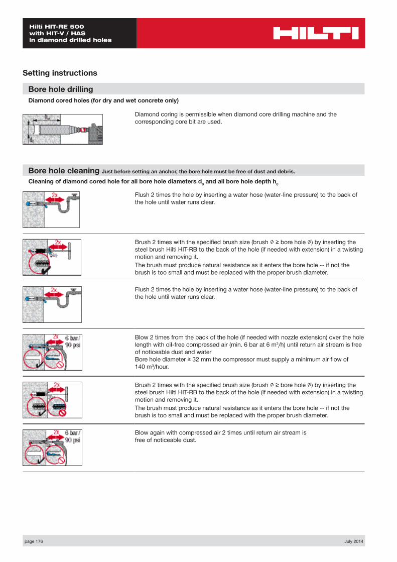
page 176 July 2014
Hilti HIT-RE 500 with HIT-V / HAS in diamond drilled holes
Setting instructions
Bore hole drillingDiamond cored holes (for dry and wet concrete only)
Diamond coring is permissible when diamond core drilling machine and the corresponding core bit are used.
Bore hole cleaning Just before setting an anchor, the bore hole must be free of dust and debris.
Cleaning of diamond cored hole for all bore hole diameters d0 and all bore hole depth h0
Flush 2 times the hole by inserting a water hose (water-line pressure) to the back of the hole until water runs clear.
Brush 2 times with the specified brush size (brush ∅ ≥ bore hole ∅) by inserting the steel brush Hilti HIT-RB to the back of the hole (if needed with extension) in a twisting motion and removing it.The brush must produce natural resistance as it enters the bore hole -- if not the brush is too small and must be replaced with the proper brush diameter.
Flush 2 times the hole by inserting a water hose (water-line pressure) to the back of the hole until water runs clear.
Blow 2 times from the back of the hole (if needed with nozzle extension) over the hole length with oil-free compressed air (min. 6 bar at 6 m3/h) until return air stream is free of noticeable dust and water Bore hole diameter ≥ 32 mm the compressor must supply a minimum air flow of 140 m³/hour.
Brush 2 times with the specified brush size (brush ∅ ≥ bore hole ∅) by inserting the steel brush Hilti HIT-RB to the back of the hole (if needed with extension) in a twisting motion and removing it.The brush must produce natural resistance as it enters the bore hole -- if not the brush is too small and must be replaced with the proper brush diameter.
Blow again with compressed air 2 times until return air stream is free of noticeable dust.
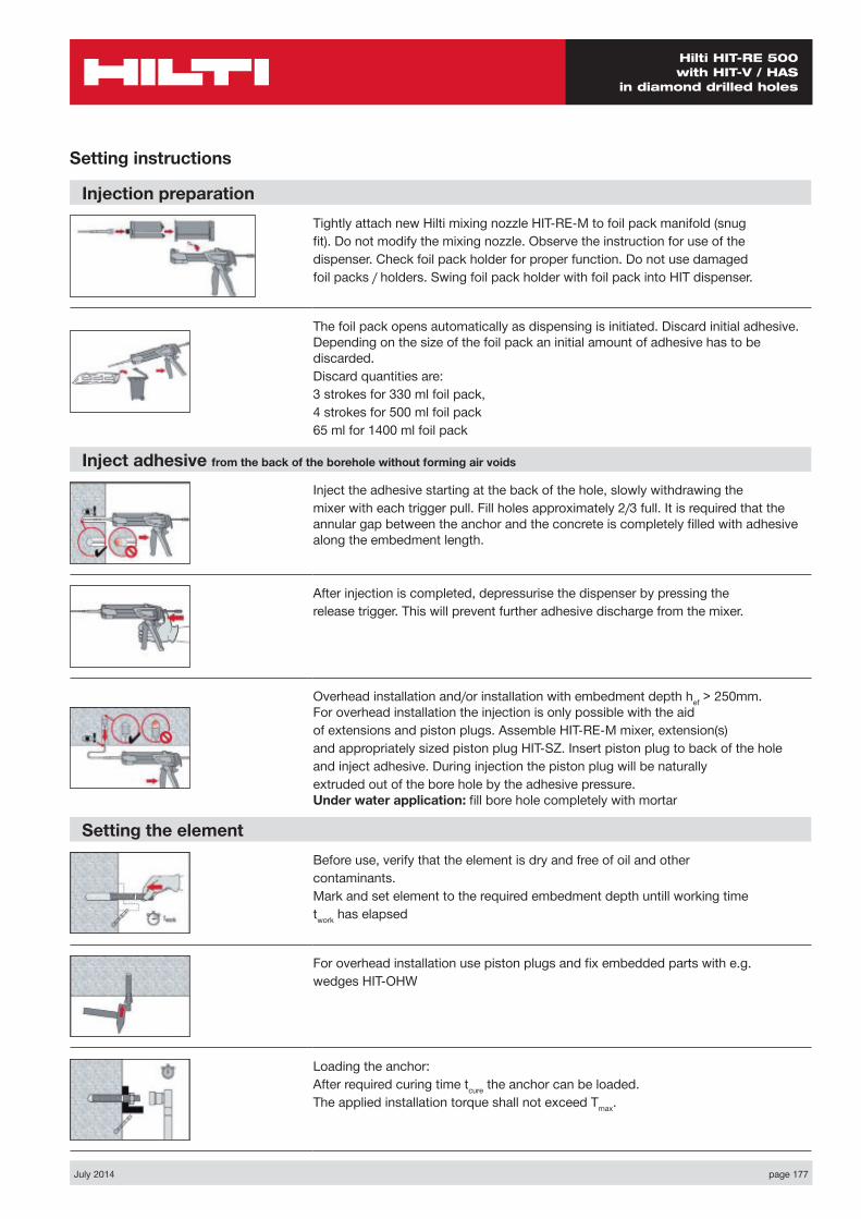
July 2014 page 177
Hilti HIT-RE 500 with HIT-V / HAS
in diamond drilled holes
Injection preparationTightly attach new Hilti mixing nozzle HIT-RE-M to foil pack manifold (snugfit). Do not modify the mixing nozzle. Observe the instruction for use of thedispenser. Check foil pack holder for proper function. Do not use damagedfoil packs / holders. Swing foil pack holder with foil pack into HIT dispenser.
The foil pack opens automatically as dispensing is initiated. Discard initial adhesive. Depending on the size of the foil pack an initial amount of adhesive has to be discarded.Discard quantities are:3 strokes for 330 ml foil pack,4 strokes for 500 ml foil pack65 ml for 1400 ml foil pack
Inject adhesive from the back of the borehole without forming air voids
Inject the adhesive starting at the back of the hole, slowly withdrawing themixer with each trigger pull. Fill holes approximately 2/3 full. It is required that the annular gap between the anchor and the concrete is completely filled with adhesive along the embedment length.
After injection is completed, depressurise the dispenser by pressing therelease trigger. This will prevent further adhesive discharge from the mixer.
Overhead installation and/or installation with embedment depth hef > 250mm. For overhead installation the injection is only possible with the aidof extensions and piston plugs. Assemble HIT-RE-M mixer, extension(s)and appropriately sized piston plug HIT-SZ. Insert piston plug to back of the holeand inject adhesive. During injection the piston plug will be naturallyextruded out of the bore hole by the adhesive pressure. Under water application: fill bore hole completely with mortar
Setting the elementBefore use, verify that the element is dry and free of oil and othercontaminants.Mark and set element to the required embedment depth untill working timetwork has elapsed
For overhead installation use piston plugs and fix embedded parts with e.g.wedges HIT-OHW
Loading the anchor:After required curing time tcure the anchor can be loaded.The applied installation torque shall not exceed Tmax.
Setting instructions
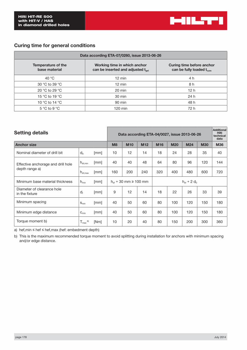
page 178 July 2014
Hilti HIT-RE 500 with HIT-V / HAS in diamond drilled holes
Data according ETA-04/0027, issue 2013-06-26Additional
Hilti technical
data
Anchor size M8 M10 M12 M16 M20 M24 M30 M36
Nominal diameter of drill bit d0 [mm] 10 12 14 18 24 28 35 40
Effective anchorage and drill hole depth range a)
hef,min [mm] 40 40 48 64 80 96 120 144
hef,max [mm] 160 200 240 320 400 480 600 720
Minimum base material thickness hmin [mm] hef + 30 mm ≥ 100 mm hef + 2 d0
Diameter of clearance hole in the fixture df [mm] 9 12 14 18 22 26 33 39
Minimum spacing smin [mm] 40 50 60 80 100 120 150 180
Minimum edge distance cmin [mm] 40 50 60 80 100 120 150 180
Torque moment b) Tmax b) [Nm] 10 20 40 80 150 200 300 360
a) hef,min ≤ hef ≤ hef,max (hef: embedment depth)b) This is the maximum recommended torque moment to avoid splitting during installation for anchors with minimum spacing
and/or edge distance.
Setting details
Curing time for general conditions
Data according ETA-07/0260, issue 2013-06-26
Temperature of the base material
Working time in which anchor can be inserted and adjusted tgel
Curing time before anchor can be fully loaded tcure
40 °C 12 min 4 h30 °C to 39 °C 12 min 8 h20 °C to 29 °C 20 min 12 h15 °C to 19 °C 30 min 24 h10 °C to 14 °C 90 min 48 h5 °C to 9 °C 120 min 72 h
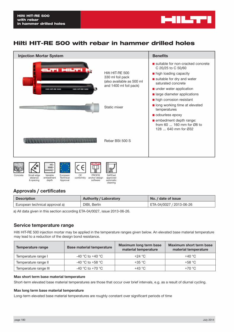
page 180 July 2014
Hilti HIT-RE 500 with rebar in hammer drilled holes
Static mixer
CE conformity
Small edge distance
& spacing
European Technical Approval
Concrete
Hilti HIT-RE 500 with rebar in hammer drilled holes
Injection Mortar System
Variable embedment
depth
Hilti HIT-RE 500330 ml foil pack(also available as 500 mland 1400 ml foil pack)
Benefits
■ suitable for non-cracked concrete C 20/25 to C 50/60
■ high loading capacity■ suitable for dry and water
saturated concrete■ under water application■ large diameter applications■ high corrosion resistant■ long working time at elevated
temperatures■ odourless epoxy■ embedment depth range:
from 60 … 160 mm for Ø8 to 128 … 640 mm for Ø32
PROFIS anchor design
software
Rebar BSt 500 S
Approvals / certificatesDescription Authority / Laboratory No. / date of issueEuropean technical approval a) DIBt, Berlin ETA-04/0027 / 2013-06-26
a) All data given in this section according ETA-04/0027, issue 2013-06-26.
Service temperature rangeHilti HIT-RE 500 injection mortar may be applied in the temperature ranges given below. An elevated base material temperature may lead to a reduction of the design bond resistance.
Temperature range Base material temperature Maximum long term base material temperature
Maximum short term base material temperature
Temperature range I -40 °C to +40 °C +24 °C +40 °CTemperature range II -40 °C to +58 °C +35 °C +58 °CTemperature range III -40 °C to +70 °C +43 °C +70 °C
Max short term base material temperatureShort-term elevated base material temperatures are those that occur over brief intervals, e.g. as a result of diurnal cycling.
Max long term base material temperatureLong-term elevated base material temperatures are roughly constant over significant periods of time
SAFEset approved automatic cleaning

July 2014 page 181
Hilti HIT-RE 500 with rebar
in hammer drilled holes
Design process for typical anchor layoutsThe design values in the tables are obtained from Profis V2.4.2 in compliance with the design method according to EOTA TR 029. Design resistance according to data given in ETA-04/0027, issue 2013-06-26.■ Influence of concrete strength ■ Influence of edge distance ■ Influence of spacing
The design method is based on the following simplification:■ No different loads are acting on individual anchors (no eccentricity)
The values are valid for the anchor configuration.
For more complex fastening applications please use the anchor design software PROFIS Anchor.
STEP 1: TENSION LOADING
The design tensile resistance NRd is the lower of:
■ Combined pull-out and concrete cone resistance NRd,p = fB,p • N*Rd,p 1
N*Rd,p is obtained from the relevant design tables
fB,p influence of concrete strength on combined pull-out and concrete cone resistance
Concrete Strengths f’c,cyl (MPa) 20 25 32 40 50fB,p 0.95 0.97 1.00 1.02 1.04
1 Data apply for dry concrete and hammer drilled holes only. For non-dry concrete multiply Nrd,p by the factor 0.83 For diamond cored holes please see chapter “HIT-RE 500 with rebar in diamond cored holes”
■ Concrete cone or concrete splitting resistance NRd,c = fB • N*Rd,c 2
N*Rd,c is obtained from the relevant design tables
fB influence of concrete strength on concrete cone resistance
Concrete Strengths f’c,cyl (MPa) 20 25 32 40 50fB 0.79 0.87 1.00 1.11 1.22
2 For non dry concrete multiply NRd,c by the factor 0.83. The definition of Dry Concrete, as per Hilti is: concrete not in contact with water before/during installation and curing.
■ Design steel resistance NRd,s
Anchor size Ø8 Ø10 Ø12 Ø14 Ø16 Ø20 Ø24 Ø28 Ø32NRd,s BSt 500 S [kN] 20.0 30.7 44.3 60.7 79.3 123.6 177.8 242.1 315.7
NRd = min { NRd,p, NRd,c, NRd,s } CHECK NRd ≥ NSd
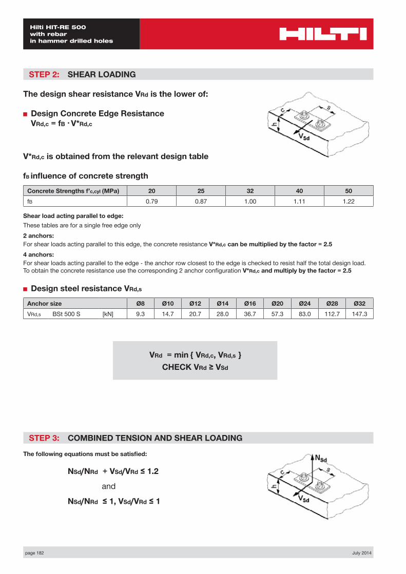
page 182 July 2014
Hilti HIT-RE 500 with rebar in hammer drilled holes
STEP 2: SHEAR LOADING
The design shear resistance VRd is the lower of:
■ Design Concrete Edge Resistance VRd,c = fB • V*Rd,c
V*Rd,c is obtained from the relevant design table
fB influence of concrete strength
Concrete Strengths f’c,cyl (MPa) 20 25 32 40 50fB 0.79 0.87 1.00 1.11 1.22
Shear load acting parallel to edge:These tables are for a single free edge only2 anchors:For shear loads acting parallel to this edge, the concrete resistance V*Rd,c can be multiplied by the factor = 2.54 anchors:For shear loads acting parallel to the edge - the anchor row closest to the edge is checked to resist half the total design load. To obtain the concrete resistance use the corresponding 2 anchor configuration V*Rd,c and multiply by the factor = 2.5
■ Design steel resistance VRd,s
Anchor size Ø8 Ø10 Ø12 Ø14 Ø16 Ø20 Ø24 Ø28 Ø32VRd,s BSt 500 S [kN] 9.3 14.7 20.7 28.0 36.7 57.3 83.0 112.7 147.3
STEP 3: COMBINED TENSION AND SHEAR LOADING
The following equations must be satisfied:
NSd/NRd + VSd/VRd ≤ 1.2
and
NSd/NRd ≤ 1, VSd/VRd ≤ 1
VRd = min { VRd,c, VRd,s } CHECK VRd ≥ VSd
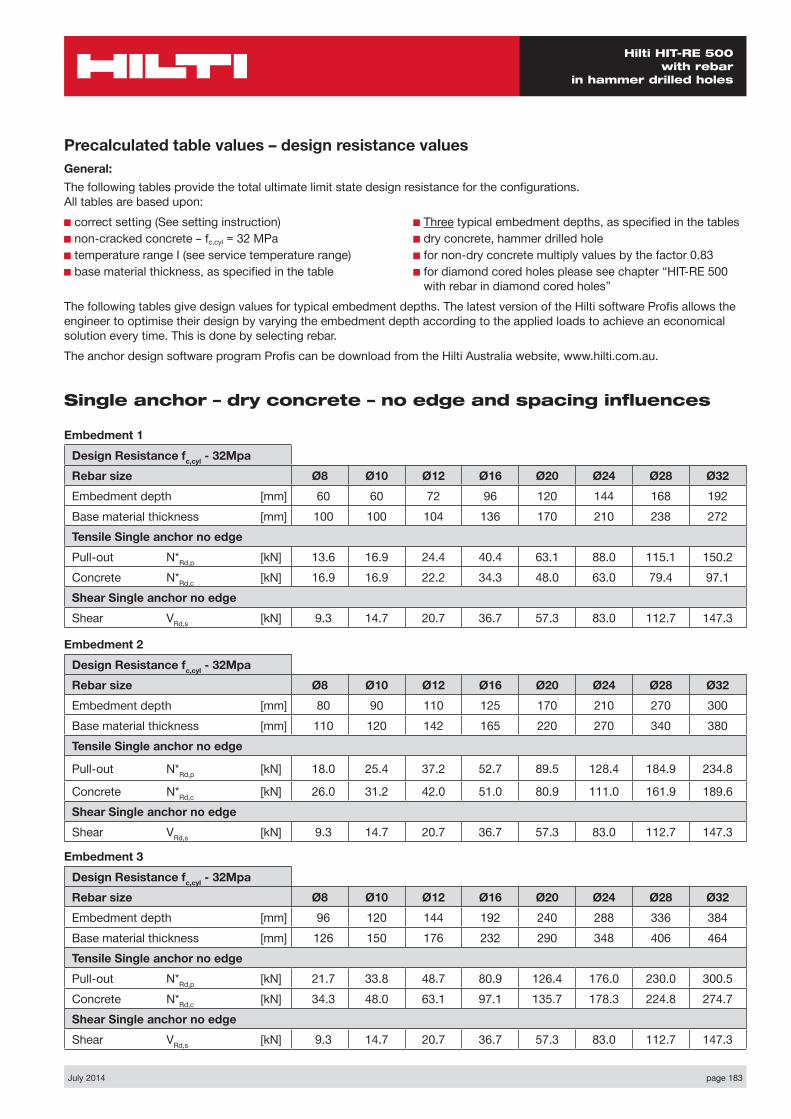
July 2014 page 183
Hilti HIT-RE 500 with rebar
in hammer drilled holes
Precalculated table values – design resistance valuesGeneral:The following tables provide the total ultimate limit state design resistance for the configurations. All tables are based upon:■ correct setting (See setting instruction)■ non-cracked concrete – fc,cyl = 32 MPa■ temperature range I (see service temperature range)■ base material thickness, as specified in the table
■ Three typical embedment depths, as specified in the tables■ dry concrete, hammer drilled hole■ for non-dry concrete multiply values by the factor 0.83■ for diamond cored holes please see chapter “HIT-RE 500
with rebar in diamond cored holes”The following tables give design values for typical embedment depths. The latest version of the Hilti software Profis allows the engineer to optimise their design by varying the embedment depth according to the applied loads to achieve an economical solution every time. This is done by selecting rebar.The anchor design software program Profis can be download from the Hilti Australia website, www.hilti.com.au.
Single anchor – dry concrete – no edge and spacing influences
Embedment 1Design Resistance fc,cyl - 32MpaRebar size Ø8 Ø10 Ø12 Ø16 Ø20 Ø24 Ø28 Ø32Embedment depth [mm] 60 60 72 96 120 144 168 192Base material thickness [mm] 100 100 104 136 170 210 238 272Tensile Single anchor no edgePull-out N*Rd,p [kN] 13.6 16.9 24.4 40.4 63.1 88.0 115.1 150.2Concrete N*Rd,c [kN] 16.9 16.9 22.2 34.3 48.0 63.0 79.4 97.1Shear Single anchor no edge Shear VRd,s [kN] 9.3 14.7 20.7 36.7 57.3 83.0 112.7 147.3
Embedment 2Design Resistance fc,cyl - 32MpaRebar size Ø8 Ø10 Ø12 Ø16 Ø20 Ø24 Ø28 Ø32Embedment depth [mm] 80 90 110 125 170 210 270 300Base material thickness [mm] 110 120 142 165 220 270 340 380Tensile Single anchor no edge
Pull-out N*Rd,p [kN] 18.0 25.4 37.2 52.7 89.5 128.4 184.9 234.8
Concrete N*Rd,c [kN] 26.0 31.2 42.0 51.0 80.9 111.0 161.9 189.6Shear Single anchor no edge Shear VRd,s [kN] 9.3 14.7 20.7 36.7 57.3 83.0 112.7 147.3
Embedment 3Design Resistance fc,cyl - 32MpaRebar size Ø8 Ø10 Ø12 Ø16 Ø20 Ø24 Ø28 Ø32Embedment depth [mm] 96 120 144 192 240 288 336 384Base material thickness [mm] 126 150 176 232 290 348 406 464Tensile Single anchor no edgePull-out N*Rd,p [kN] 21.7 33.8 48.7 80.9 126.4 176.0 230.0 300.5Concrete N*Rd,c [kN] 34.3 48.0 63.1 97.1 135.7 178.3 224.8 274.7Shear Single anchor no edge Shear VRd,s [kN] 9.3 14.7 20.7 36.7 57.3 83.0 112.7 147.3
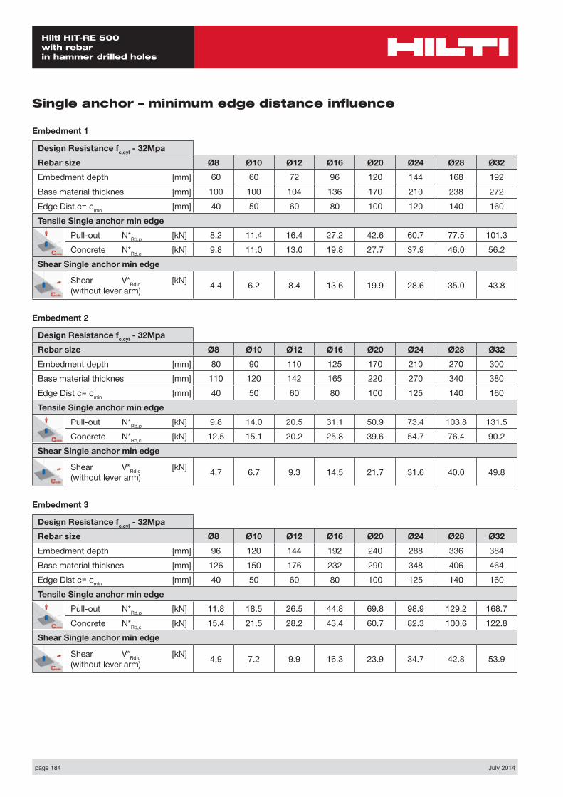
page 184 July 2014
Hilti HIT-RE 500 with rebar in hammer drilled holes
Single anchor – minimum edge distance influence
Embedment 1
Design Resistance fc,cyl - 32MpaRebar size Ø8 Ø10 Ø12 Ø16 Ø20 Ø24 Ø28 Ø32Embedment depth [mm] 60 60 72 96 120 144 168 192Base material thicknes [mm] 100 100 104 136 170 210 238 272Edge Dist c= cmin [mm] 40 50 60 80 100 120 140 160Tensile Single anchor min edge
Pull-out N*Rd,p [kN] 8.2 11.4 16.4 27.2 42.6 60.7 77.5 101.3Concrete N*Rd,c [kN] 9.8 11.0 13.0 19.8 27.7 37.9 46.0 56.2
Shear Single anchor min edge
Shear V*Rd,c [kN] (without lever arm) 4.4 6.2 8.4 13.6 19.9 28.6 35.0 43.8
Embedment 2
Design Resistance fc,cyl - 32MpaRebar size Ø8 Ø10 Ø12 Ø16 Ø20 Ø24 Ø28 Ø32Embedment depth [mm] 80 90 110 125 170 210 270 300Base material thicknes [mm] 110 120 142 165 220 270 340 380Edge Dist c= cmin [mm] 40 50 60 80 100 125 140 160Tensile Single anchor min edge
Pull-out N*Rd,p [kN] 9.8 14.0 20.5 31.1 50.9 73.4 103.8 131.5Concrete N*Rd,c [kN] 12.5 15.1 20.2 25.8 39.6 54.7 76.4 90.2
Shear Single anchor min edge
Shear V*Rd,c [kN] (without lever arm) 4.7 6.7 9.3 14.5 21.7 31.6 40.0 49.8
Embedment 3
Design Resistance fc,cyl - 32MpaRebar size Ø8 Ø10 Ø12 Ø16 Ø20 Ø24 Ø28 Ø32Embedment depth [mm] 96 120 144 192 240 288 336 384Base material thicknes [mm] 126 150 176 232 290 348 406 464Edge Dist c= cmin [mm] 40 50 60 80 100 125 140 160Tensile Single anchor min edge
Pull-out N*Rd,p [kN] 11.8 18.5 26.5 44.8 69.8 98.9 129.2 168.7Concrete N*Rd,c [kN] 15.4 21.5 28.2 43.4 60.7 82.3 100.6 122.8
Shear Single anchor min edge
Shear V*Rd,c [kN] (without lever arm) 4.9 7.2 9.9 16.3 23.9 34.7 42.8 53.9

July 2014 page 185
Hilti HIT-RE 500 with rebar
in hammer drilled holes
2 Anchors – min spacing influence
Embedment 1
Design Resistance fc,cyl - 32MpaRebar size Ø8 Ø10 Ø12 Ø16 Ø20 Ø24 Ø28 Ø32Embedment depth [mm] 60 60 72 96 120 144 168 192Base material thicknes [mm] 100 100 104 136 170 210 238 272Spacing Dist s= smin [mm] 40 50 60 80 100 125 140 160Tensile NRd
Pull-out N*Rd,p [kN] 17.5 21.6 31.2 51.6 80.8 113.5 147.0 101.3Concrete N*Rd,c [kN] 20.5 21.4 26.9 41.3 57.7 77.4 95.6 56.2
Shear VRd VRd,s steel (per anchor) [kN] 9.3 14.7 20.7 36.7 57.3 83.0 112.6 147.3V*Rd,c pryout [kN] N/A 113.0 190.0 236.9 289.5
Embedment 2
Design Resistance fc,cyl - 32MpaRebar size Ø8 Ø10 Ø12 Ø16 Ø20 Ø24 Ø28 Ø32Embedment depth [mm] 80 90 110 125 170 210 270 300Base material thicknes [mm] 110 120 142 165 220 270 340 380Spacing Dist s= smin [mm] 40 50 60 80 100 125 140 160Tensile NRd
Pull-out N*Rd,p [kN] 23.4 31.9 45.7 64.0 107.2 151.4 220.0 279.4Concrete N*Rd,c [kN] 29.2 35.0 47.2 58.3 91.4 125.8 180.5 211.9
Shear VRd VRd,s steel (per anchor) [kN] 9.3 14.7 20.7 36.7 57.3 83.0 112.6 147.3
Embedment 3
Design Resistance fc,cyl - 32MpaRebar size Ø8 Ø10 Ø12 Ø16 Ø20 Ø24 Ø28 Ø32Embedment depth [mm] 96 120 144 192 240 288 336 384Base material thicknes [mm] 126 150 176 232 290 348 406 464Spacing Dist s= smin [mm] 40 50 60 80 100 125 140 160Tensile NRd
Pull-out N*Rd,p [kN] 28.4 43.7 61.7 101.0 152.9 210.1 273.8 357.6Concrete N*Rd,c [kN] 37.4 52.4 68.9 106.1 148.2 199.9 245.5 300.0
Shear VRd
VRd,s steel (per anchor) [kN] 9.3 14.7 20.7 36.7 57.3 83.0 112.6 147.3
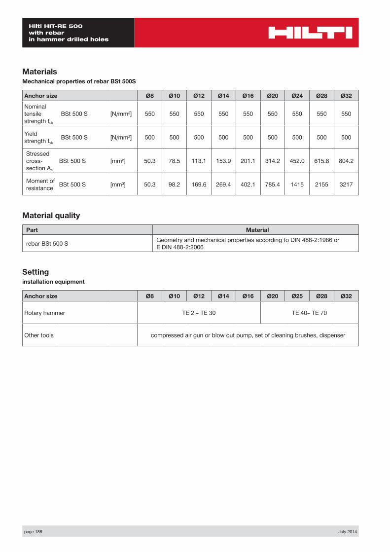
page 186 July 2014
Hilti HIT-RE 500 with rebar in hammer drilled holes
MaterialsMechanical properties of rebar BSt 500S
Anchor size Ø8 Ø10 Ø12 Ø14 Ø16 Ø20 Ø24 Ø28 Ø32
Nominal tensile strength fuk
BSt 500 S [N/mm²] 550 550 550 550 550 550 550 550 550
Yield strength fyk
BSt 500 S [N/mm²] 500 500 500 500 500 500 500 500 500
Stressed cross- section As
BSt 500 S [mm²] 50.3 78.5 113.1 153.9 201.1 314.2 452.0 615.8 804.2
Moment of resistance BSt 500 S [mm³] 50.3 98.2 169.6 269.4 402.1 785.4 1415 2155 3217
Material quality
Part Material
rebar BSt 500 S Geometry and mechanical properties according to DIN 488-2:1986 or E DIN 488-2:2006
Settinginstallation equipment
Anchor size Ø8 Ø10 Ø12 Ø14 Ø16 Ø20 Ø25 Ø28 Ø32
Rotary hammer TE 2 – TE 30 TE 40– TE 70
Other tools compressed air gun or blow out pump, set of cleaning brushes, dispenser
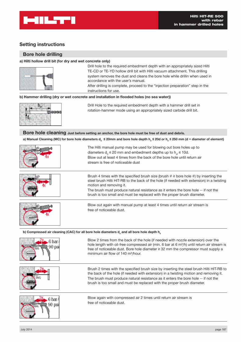
July 2014 page 187
Hilti HIT-RE 500 with rebar
in hammer drilled holes
Setting instructions
Bore hole drillinga) Hilti hollow drill bit (for dry and wet concrete only)
Drill hole to the required embedment depth with an appropriately sized HiltiTE-CD or TE-YD hollow drill bit with Hilti vacuum attachment. This drillingsystem removes the dust and cleans the bore hole while drillin when used in accordance with the user’s manual.After drilling is complete, proceed to the “injection preparation” step in theinstructions for use.
b) Hammer drilling (dry or wet concrete and installation in flooded holes (no sea water))
Drill Hole to the required embedment depth with a hammer drill set inrotation-hammer mode using an appropriately sized carbide drill bit.
Bore hole cleaning Just before setting an anchor, the bore hole must be free of dust and debris.
a) Manual Cleaning (MC) for bore hole diameters d0 ≤ 20mm and bore hole depth h0 ≤ 20d or h0 ≤ 250 mm (d = diameter of element)
The Hilti manual pump may be used for blowing out bore holes up todiameters d0 ≤ 20 mm and embedment depths up to hef ≤ 10d.Blow out at least 4 times from the back of the bore hole until return airstream is free of noticeable dust
Brush 4 times with the specified brush size (brush ∅ ≥ bore hole ∅) by inserting the steel brush Hilti HIT-RB to the back of the hole (if needed with extension) in a twisting motion and removing it.The brush must produce natural resistance as it enters the bore hole -- if not the brush is too small and must be replaced with the proper brush diameter.
Blow out again with manual pump at least 4 times until return air stream isfree of noticeable dust.
b) Compressed air cleaning (CAC) for all bore hole diameters d0 and all bore hole depth h0
Blow 2 times from the back of the hole (if needed with nozzle extension) over the hole length with oil-free compressed air (min. 6 bar at 6 m³/h) until return air stream is free of noticeable dust. Bore hole diameter ≥ 32 mm the compressor must supply a minimum air flow of 140 m³/hour.
Brush 2 times with the specified brush size by inserting the steel brush Hilti HIT-RB to the back of the hole (if needed with extension) in a twisting motion and removing it.The brush must produce natural resistance as it enters the bore hole -- if not the brush is too small and must be replaced with the proper brush diameter.
Blow again with compressed air 2 times until return air stream isfree of noticeable dust.
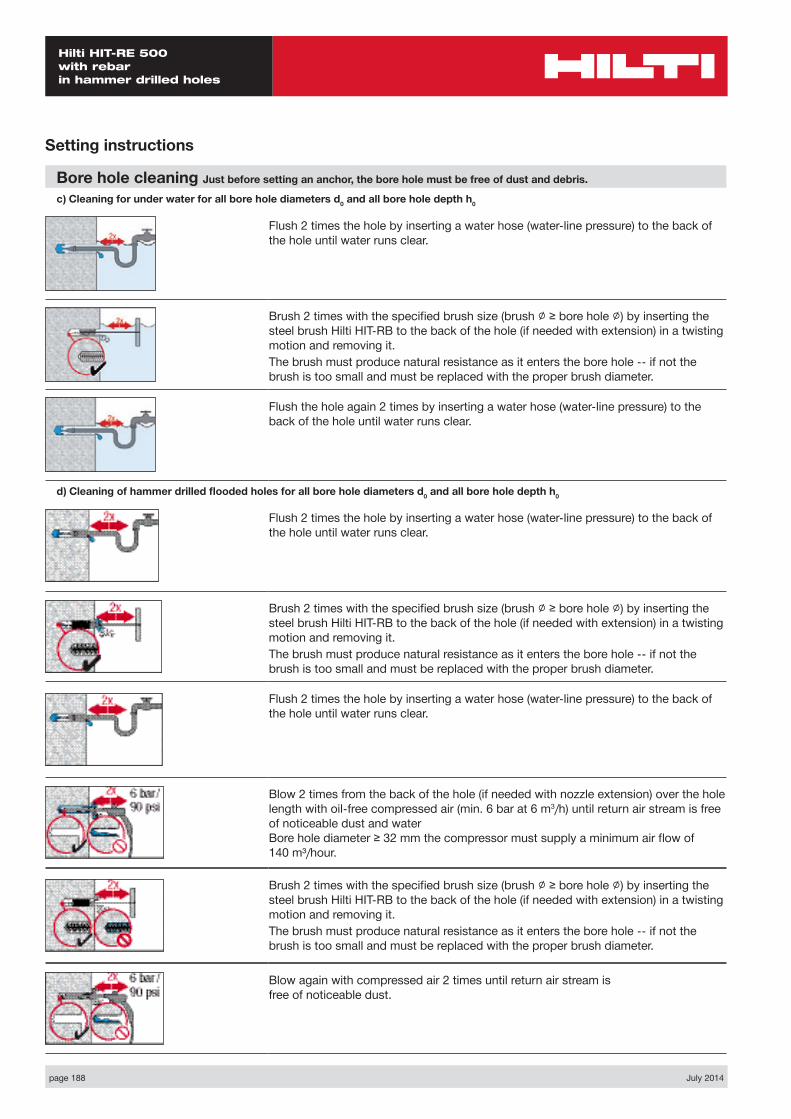
page 188 July 2014
Hilti HIT-RE 500 with rebar in hammer drilled holes
Setting instructions
Bore hole cleaning Just before setting an anchor, the bore hole must be free of dust and debris.
c) Cleaning for under water for all bore hole diameters d0 and all bore hole depth h0
Flush 2 times the hole by inserting a water hose (water-line pressure) to the back of the hole until water runs clear.
Brush 2 times with the specified brush size (brush ∅ ≥ bore hole ∅) by inserting the steel brush Hilti HIT-RB to the back of the hole (if needed with extension) in a twisting motion and removing it.The brush must produce natural resistance as it enters the bore hole -- if not the brush is too small and must be replaced with the proper brush diameter.
Flush the hole again 2 times by inserting a water hose (water-line pressure) to the back of the hole until water runs clear.
d) Cleaning of hammer drilled flooded holes for all bore hole diameters d0 and all bore hole depth h0
Flush 2 times the hole by inserting a water hose (water-line pressure) to the back of the hole until water runs clear.
Brush 2 times with the specified brush size (brush ∅ ≥ bore hole ∅) by inserting the steel brush Hilti HIT-RB to the back of the hole (if needed with extension) in a twisting motion and removing it.The brush must produce natural resistance as it enters the bore hole -- if not the brush is too small and must be replaced with the proper brush diameter.
Flush 2 times the hole by inserting a water hose (water-line pressure) to the back of the hole until water runs clear.
Blow 2 times from the back of the hole (if needed with nozzle extension) over the hole length with oil-free compressed air (min. 6 bar at 6 m3/h) until return air stream is free of noticeable dust and water Bore hole diameter ≥ 32 mm the compressor must supply a minimum air flow of 140 m³/hour.
Brush 2 times with the specified brush size (brush ∅ ≥ bore hole ∅) by inserting the steel brush Hilti HIT-RB to the back of the hole (if needed with extension) in a twisting motion and removing it.The brush must produce natural resistance as it enters the bore hole -- if not the brush is too small and must be replaced with the proper brush diameter.
Blow again with compressed air 2 times until return air stream is free of noticeable dust.
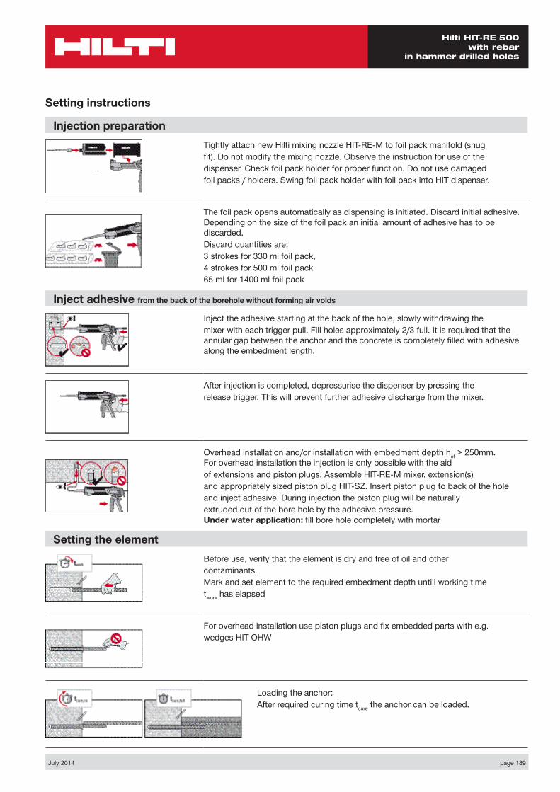
July 2014 page 189
Hilti HIT-RE 500 with rebar
in hammer drilled holes
Injection preparationTightly attach new Hilti mixing nozzle HIT-RE-M to foil pack manifold (snugfit). Do not modify the mixing nozzle. Observe the instruction for use of thedispenser. Check foil pack holder for proper function. Do not use damagedfoil packs / holders. Swing foil pack holder with foil pack into HIT dispenser.
The foil pack opens automatically as dispensing is initiated. Discard initial adhesive. Depending on the size of the foil pack an initial amount of adhesive has to be discarded.Discard quantities are:3 strokes for 330 ml foil pack,4 strokes for 500 ml foil pack65 ml for 1400 ml foil pack
Inject adhesive from the back of the borehole without forming air voids
Inject the adhesive starting at the back of the hole, slowly withdrawing themixer with each trigger pull. Fill holes approximately 2/3 full. It is required that the annular gap between the anchor and the concrete is completely filled with adhesive along the embedment length.
After injection is completed, depressurise the dispenser by pressing therelease trigger. This will prevent further adhesive discharge from the mixer.
Overhead installation and/or installation with embedment depth hef > 250mm. For overhead installation the injection is only possible with the aidof extensions and piston plugs. Assemble HIT-RE-M mixer, extension(s)and appropriately sized piston plug HIT-SZ. Insert piston plug to back of the holeand inject adhesive. During injection the piston plug will be naturallyextruded out of the bore hole by the adhesive pressure. Under water application: fill bore hole completely with mortar
Setting the elementBefore use, verify that the element is dry and free of oil and othercontaminants.Mark and set element to the required embedment depth untill working timetwork has elapsed
For overhead installation use piston plugs and fix embedded parts with e.g.wedges HIT-OHW
Loading the anchor:After required curing time tcure the anchor can be loaded.
Setting instructions
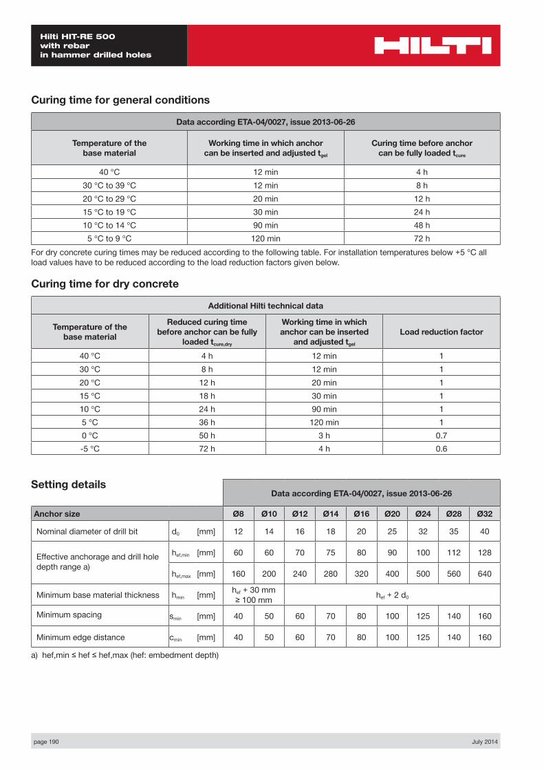
page 190 July 2014
Hilti HIT-RE 500 with rebar in hammer drilled holes
Setting details
Curing time for general conditions
Data according ETA-04/0027, issue 2013-06-26
Temperature of the base material
Working time in which anchor can be inserted and adjusted tgel
Curing time before anchor can be fully loaded tcure
40 °C 12 min 4 h30 °C to 39 °C 12 min 8 h20 °C to 29 °C 20 min 12 h15 °C to 19 °C 30 min 24 h10 °C to 14 °C 90 min 48 h5 °C to 9 °C 120 min 72 h
For dry concrete curing times may be reduced according to the following table. For installation temperatures below +5 °C all load values have to be reduced according to the load reduction factors given below.
Curing time for dry concrete
Additional Hilti technical data
Temperature of the base material
Reduced curing time before anchor can be fully
loaded tcure,dry
Working time in which anchor can be inserted
and adjusted tgel
Load reduction factor
40 °C 4 h 12 min 130 °C 8 h 12 min 120 °C 12 h 20 min 115 °C 18 h 30 min 110 °C 24 h 90 min 15 °C 36 h 120 min 10 °C 50 h 3 h 0.7-5 °C 72 h 4 h 0.6
Data according ETA-04/0027, issue 2013-06-26
Anchor size Ø8 Ø10 Ø12 Ø14 Ø16 Ø20 Ø24 Ø28 Ø32
Nominal diameter of drill bit d0 [mm] 12 14 16 18 20 25 32 35 40
Effective anchorage and drill hole depth range a)
hef,min [mm] 60 60 70 75 80 90 100 112 128
hef,max [mm] 160 200 240 280 320 400 500 560 640
Minimum base material thickness hmin [mm] hef + 30 mm ≥ 100 mm hef + 2 d0
Minimum spacing smin [mm] 40 50 60 70 80 100 125 140 160
Minimum edge distance cmin [mm] 40 50 60 70 80 100 125 140 160
a) hef,min ≤ hef ≤ hef,max (hef: embedment depth)
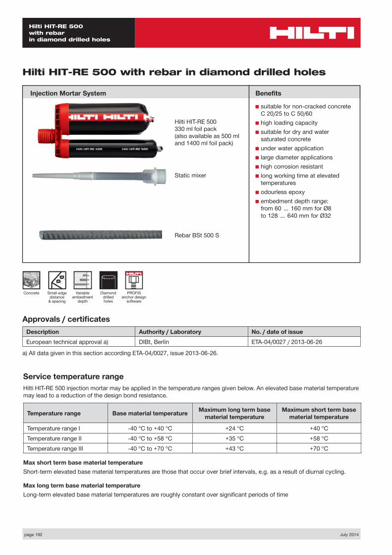
page 192 July 2014
Hilti HIT-RE 500 with rebar in diamond drilled holes
Static mixer
Diamond drilled holes
Small edge distance
& spacing
Concrete
Hilti HIT-RE 500 with rebar in diamond drilled holes
Injection Mortar System
Variable embedment
depth
Hilti HIT-RE 500330 ml foil pack(also available as 500 mland 1400 ml foil pack)
Approvals / certificatesDescription Authority / Laboratory No. / date of issueEuropean technical approval a) DIBt, Berlin ETA-04/0027 / 2013-06-26
a) All data given in this section according ETA-04/0027, issue 2013-06-26.
Service temperature rangeHilti HIT-RE 500 injection mortar may be applied in the temperature ranges given below. An elevated base material temperature may lead to a reduction of the design bond resistance.
Temperature range Base material temperature Maximum long term base material temperature
Maximum short term base material temperature
Temperature range I -40 °C to +40 °C +24 °C +40 °CTemperature range II -40 °C to +58 °C +35 °C +58 °CTemperature range III -40 °C to +70 °C +43 °C +70 °C
Max short term base material temperatureShort-term elevated base material temperatures are those that occur over brief intervals, e.g. as a result of diurnal cycling.
Max long term base material temperatureLong-term elevated base material temperatures are roughly constant over significant periods of time
Benefits
■ suitable for non-cracked concrete C 20/25 to C 50/60
■ high loading capacity■ suitable for dry and water
saturated concrete■ under water application■ large diameter applications■ high corrosion resistant■ long working time at elevated
temperatures■ odourless epoxy■ embedment depth range:
from 60 … 160 mm for Ø8 to 128 … 640 mm for Ø32
PROFIS anchor design
software
Rebar BSt 500 S
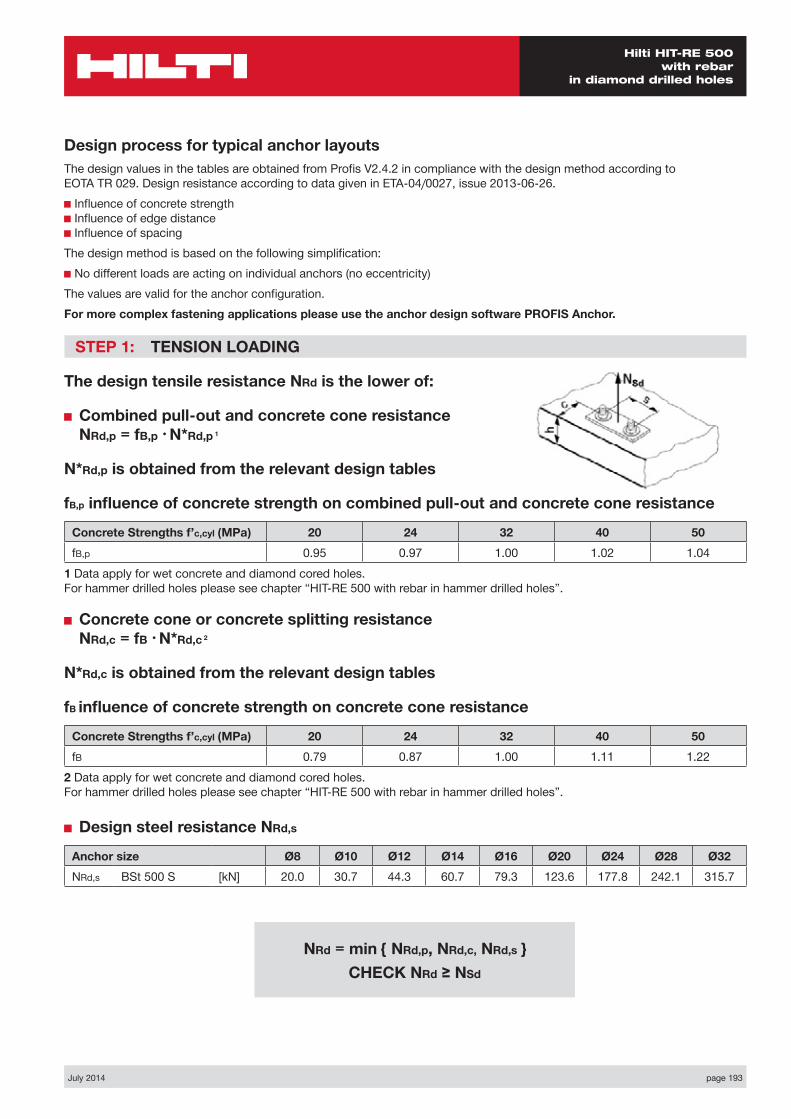
July 2014 page 193
Hilti HIT-RE 500 with rebar
in diamond drilled holes
Design process for typical anchor layoutsThe design values in the tables are obtained from Profis V2.4.2 in compliance with the design method according to EOTA TR 029. Design resistance according to data given in ETA-04/0027, issue 2013-06-26.■ Influence of concrete strength ■ Influence of edge distance ■ Influence of spacingThe design method is based on the following simplification:■ No different loads are acting on individual anchors (no eccentricity)The values are valid for the anchor configuration.For more complex fastening applications please use the anchor design software PROFIS Anchor.
STEP 1: TENSION LOADING
The design tensile resistance NRd is the lower of:
■ Combined pull-out and concrete cone resistance NRd,p = fB,p • N*Rd,p 1
N*Rd,p is obtained from the relevant design tables
fB,p influence of concrete strength on combined pull-out and concrete cone resistance
Concrete Strengths f’c,cyl (MPa) 20 24 32 40 50fB,p 0.95 0.97 1.00 1.02 1.04
1 Data apply for wet concrete and diamond cored holes. For hammer drilled holes please see chapter “HIT-RE 500 with rebar in hammer drilled holes”.
■ Concrete cone or concrete splitting resistance NRd,c = fB • N*Rd,c 2
N*Rd,c is obtained from the relevant design tables
fB influence of concrete strength on concrete cone resistance
Concrete Strengths f’c,cyl (MPa) 20 24 32 40 50fB 0.79 0.87 1.00 1.11 1.22
2 Data apply for wet concrete and diamond cored holes. For hammer drilled holes please see chapter “HIT-RE 500 with rebar in hammer drilled holes”.
■ Design steel resistance NRd,s
Anchor size Ø8 Ø10 Ø12 Ø14 Ø16 Ø20 Ø24 Ø28 Ø32NRd,s BSt 500 S [kN] 20.0 30.7 44.3 60.7 79.3 123.6 177.8 242.1 315.7
NRd = min { NRd,p, NRd,c, NRd,s } CHECK NRd ≥ NSd
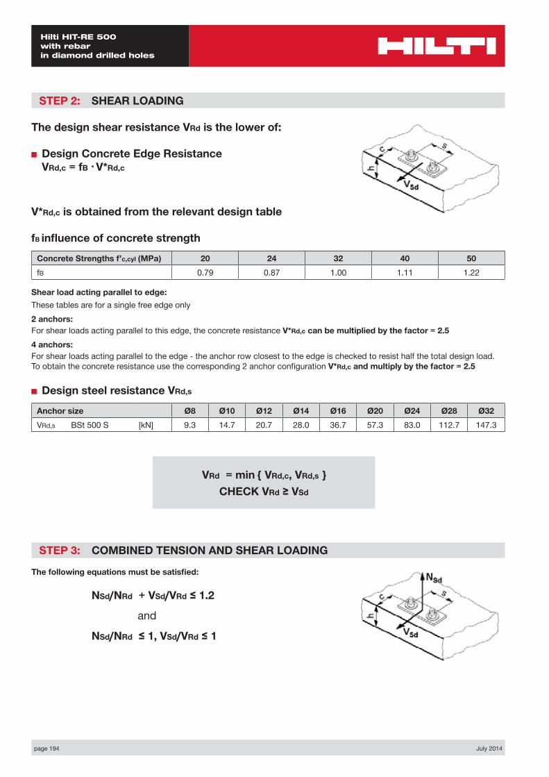
page 194 July 2014
Hilti HIT-RE 500 with rebar in diamond drilled holes
STEP 2: SHEAR LOADING
The design shear resistance VRd is the lower of:
■ Design Concrete Edge Resistance VRd,c = fB • V*Rd,c
V*Rd,c is obtained from the relevant design table
fB influence of concrete strength
Concrete Strengths f’c,cyl (MPa) 20 24 32 40 50fB 0.79 0.87 1.00 1.11 1.22
Shear load acting parallel to edge:These tables are for a single free edge only2 anchors:For shear loads acting parallel to this edge, the concrete resistance V*Rd,c can be multiplied by the factor = 2.54 anchors:For shear loads acting parallel to the edge - the anchor row closest to the edge is checked to resist half the total design load. To obtain the concrete resistance use the corresponding 2 anchor configuration V*Rd,c and multiply by the factor = 2.5
■ Design steel resistance VRd,s
Anchor size Ø8 Ø10 Ø12 Ø14 Ø16 Ø20 Ø24 Ø28 Ø32VRd,s BSt 500 S [kN] 9.3 14.7 20.7 28.0 36.7 57.3 83.0 112.7 147.3
STEP 3: COMBINED TENSION AND SHEAR LOADING
The following equations must be satisfied:
NSd/NRd + VSd/VRd ≤ 1.2
and
NSd/NRd ≤ 1, VSd/VRd ≤ 1
VRd = min { VRd,c, VRd,s } CHECK VRd ≥ VSd
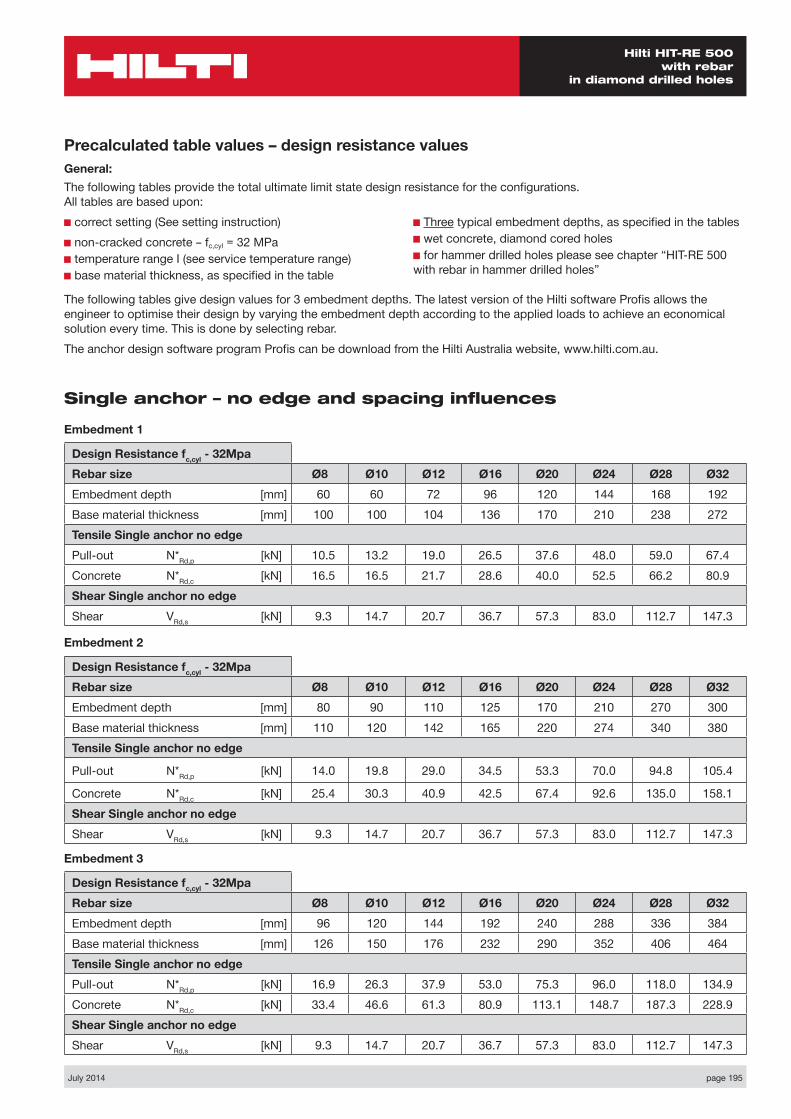
July 2014 page 195
Hilti HIT-RE 500 with rebar
in diamond drilled holes
Precalculated table values – design resistance valuesGeneral:The following tables provide the total ultimate limit state design resistance for the configurations. All tables are based upon:■ correct setting (See setting instruction)■ non-cracked concrete – fc,cyl = 32 MPa■ temperature range I (see service temperature range)■ base material thickness, as specified in the table
■ Three typical embedment depths, as specified in the tables■ wet concrete, diamond cored holes■ for hammer drilled holes please see chapter “HIT-RE 500 with rebar in hammer drilled holes”
The following tables give design values for 3 embedment depths. The latest version of the Hilti software Profis allows the engineer to optimise their design by varying the embedment depth according to the applied loads to achieve an economical solution every time. This is done by selecting rebar.The anchor design software program Profis can be download from the Hilti Australia website, www.hilti.com.au.
Single anchor – no edge and spacing influences
Embedment 1
Design Resistance fc,cyl - 32MpaRebar size Ø8 Ø10 Ø12 Ø16 Ø20 Ø24 Ø28 Ø32Embedment depth [mm] 60 60 72 96 120 144 168 192Base material thickness [mm] 100 100 104 136 170 210 238 272Tensile Single anchor no edgePull-out N*Rd,p [kN] 10.5 13.2 19.0 26.5 37.6 48.0 59.0 67.4Concrete N*Rd,c [kN] 16.5 16.5 21.7 28.6 40.0 52.5 66.2 80.9Shear Single anchor no edge Shear VRd,s [kN] 9.3 14.7 20.7 36.7 57.3 83.0 112.7 147.3
Embedment 2
Design Resistance fc,cyl - 32MpaRebar size Ø8 Ø10 Ø12 Ø16 Ø20 Ø24 Ø28 Ø32Embedment depth [mm] 80 90 110 125 170 210 270 300Base material thickness [mm] 110 120 142 165 220 274 340 380Tensile Single anchor no edge
Pull-out N*Rd,p [kN] 14.0 19.8 29.0 34.5 53.3 70.0 94.8 105.4
Concrete N*Rd,c [kN] 25.4 30.3 40.9 42.5 67.4 92.6 135.0 158.1Shear Single anchor no edge Shear VRd,s [kN] 9.3 14.7 20.7 36.7 57.3 83.0 112.7 147.3
Embedment 3
Design Resistance fc,cyl - 32MpaRebar size Ø8 Ø10 Ø12 Ø16 Ø20 Ø24 Ø28 Ø32Embedment depth [mm] 96 120 144 192 240 288 336 384Base material thickness [mm] 126 150 176 232 290 352 406 464Tensile Single anchor no edgePull-out N*Rd,p [kN] 16.9 26.3 37.9 53.0 75.3 96.0 118.0 134.9Concrete N*Rd,c [kN] 33.4 46.6 61.3 80.9 113.1 148.7 187.3 228.9Shear Single anchor no edge Shear VRd,s [kN] 9.3 14.7 20.7 36.7 57.3 83.0 112.7 147.3
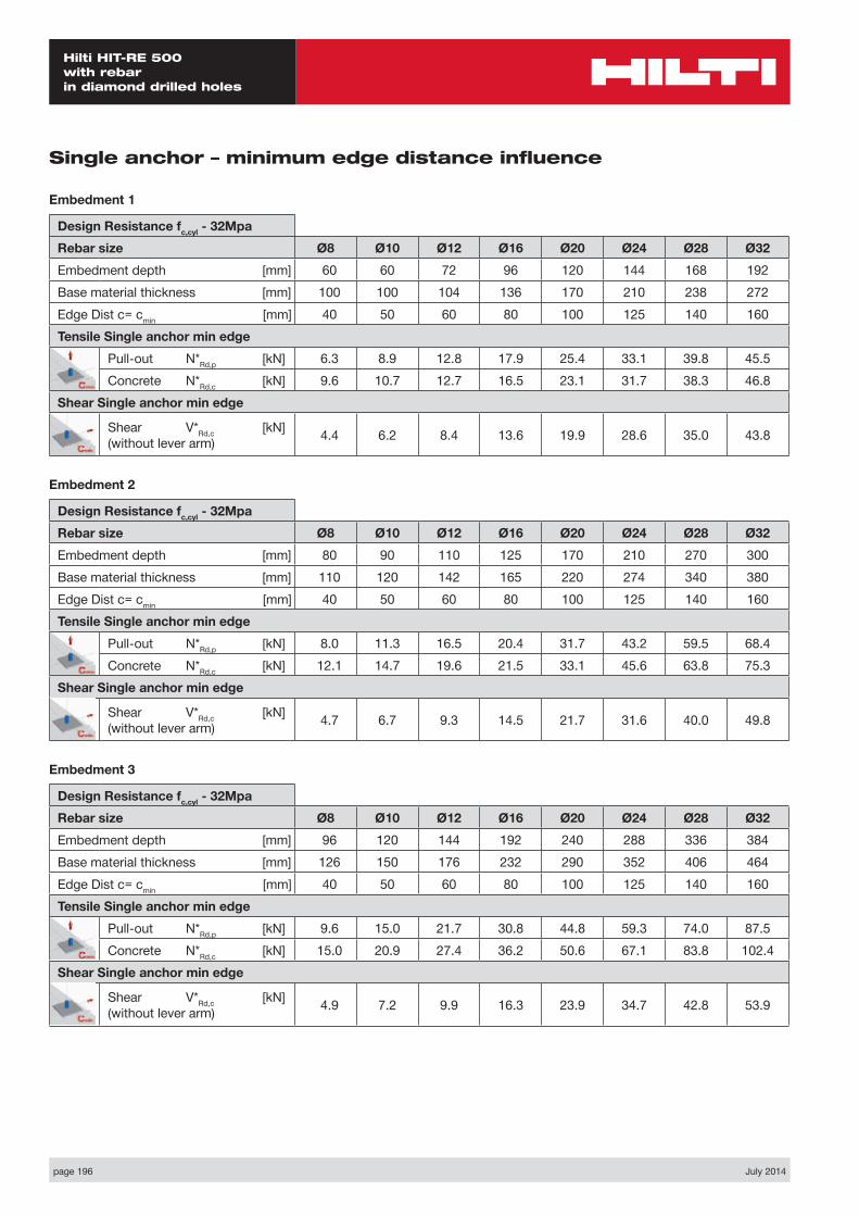
page 196 July 2014
Hilti HIT-RE 500 with rebar in diamond drilled holes
Single anchor – minimum edge distance influence
Embedment 1
Design Resistance fc,cyl - 32MpaRebar size Ø8 Ø10 Ø12 Ø16 Ø20 Ø24 Ø28 Ø32Embedment depth [mm] 60 60 72 96 120 144 168 192Base material thickness [mm] 100 100 104 136 170 210 238 272Edge Dist c= cmin [mm] 40 50 60 80 100 125 140 160Tensile Single anchor min edge
Pull-out N*Rd,p [kN] 6.3 8.9 12.8 17.9 25.4 33.1 39.8 45.5Concrete N*Rd,c [kN] 9.6 10.7 12.7 16.5 23.1 31.7 38.3 46.8
Shear Single anchor min edge
Shear V*Rd,c [kN] (without lever arm) 4.4 6.2 8.4 13.6 19.9 28.6 35.0 43.8
Embedment 2
Design Resistance fc,cyl - 32MpaRebar size Ø8 Ø10 Ø12 Ø16 Ø20 Ø24 Ø28 Ø32Embedment depth [mm] 80 90 110 125 170 210 270 300Base material thickness [mm] 110 120 142 165 220 274 340 380Edge Dist c= cmin [mm] 40 50 60 80 100 125 140 160Tensile Single anchor min edge
Pull-out N*Rd,p [kN] 8.0 11.3 16.5 20.4 31.7 43.2 59.5 68.4Concrete N*Rd,c [kN] 12.1 14.7 19.6 21.5 33.1 45.6 63.8 75.3
Shear Single anchor min edge
Shear V*Rd,c [kN] (without lever arm) 4.7 6.7 9.3 14.5 21.7 31.6 40.0 49.8
Embedment 3
Design Resistance fc,cyl - 32MpaRebar size Ø8 Ø10 Ø12 Ø16 Ø20 Ø24 Ø28 Ø32Embedment depth [mm] 96 120 144 192 240 288 336 384Base material thickness [mm] 126 150 176 232 290 352 406 464Edge Dist c= cmin [mm] 40 50 60 80 100 125 140 160Tensile Single anchor min edge
Pull-out N*Rd,p [kN] 9.6 15.0 21.7 30.8 44.8 59.3 74.0 87.5Concrete N*Rd,c [kN] 15.0 20.9 27.4 36.2 50.6 67.1 83.8 102.4
Shear Single anchor min edge
Shear V*Rd,c [kN] (without lever arm) 4.9 7.2 9.9 16.3 23.9 34.7 42.8 53.9
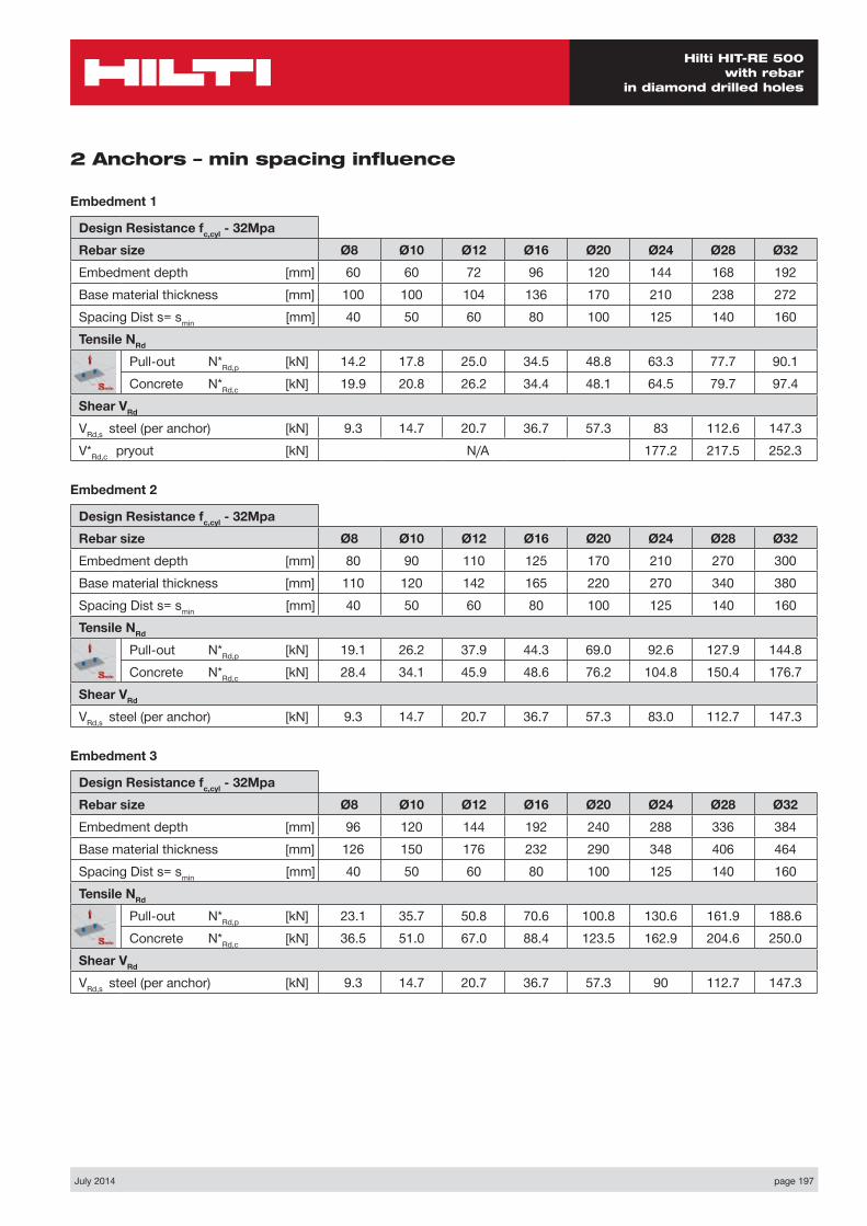
July 2014 page 197
Hilti HIT-RE 500 with rebar
in diamond drilled holes
2 Anchors – min spacing influence
Embedment 1
Design Resistance fc,cyl - 32MpaRebar size Ø8 Ø10 Ø12 Ø16 Ø20 Ø24 Ø28 Ø32Embedment depth [mm] 60 60 72 96 120 144 168 192Base material thickness [mm] 100 100 104 136 170 210 238 272Spacing Dist s= smin [mm] 40 50 60 80 100 125 140 160Tensile NRd
Pull-out N*Rd,p [kN] 14.2 17.8 25.0 34.5 48.8 63.3 77.7 90.1Concrete N*Rd,c [kN] 19.9 20.8 26.2 34.4 48.1 64.5 79.7 97.4
Shear VRd VRd,s steel (per anchor) [kN] 9.3 14.7 20.7 36.7 57.3 83 112.6 147.3V*Rd,c pryout [kN] N/A 177.2 217.5 252.3
Embedment 2
Design Resistance fc,cyl - 32MpaRebar size Ø8 Ø10 Ø12 Ø16 Ø20 Ø24 Ø28 Ø32Embedment depth [mm] 80 90 110 125 170 210 270 300Base material thickness [mm] 110 120 142 165 220 270 340 380Spacing Dist s= smin [mm] 40 50 60 80 100 125 140 160Tensile NRd
Pull-out N*Rd,p [kN] 19.1 26.2 37.9 44.3 69.0 92.6 127.9 144.8Concrete N*Rd,c [kN] 28.4 34.1 45.9 48.6 76.2 104.8 150.4 176.7
Shear VRd VRd,s steel (per anchor) [kN] 9.3 14.7 20.7 36.7 57.3 83.0 112.7 147.3
Embedment 3
Design Resistance fc,cyl - 32MpaRebar size Ø8 Ø10 Ø12 Ø16 Ø20 Ø24 Ø28 Ø32Embedment depth [mm] 96 120 144 192 240 288 336 384Base material thickness [mm] 126 150 176 232 290 348 406 464Spacing Dist s= smin [mm] 40 50 60 80 100 125 140 160Tensile NRd
Pull-out N*Rd,p [kN] 23.1 35.7 50.8 70.6 100.8 130.6 161.9 188.6Concrete N*Rd,c [kN] 36.5 51.0 67.0 88.4 123.5 162.9 204.6 250.0
Shear VRd VRd,s steel (per anchor) [kN] 9.3 14.7 20.7 36.7 57.3 90 112.7 147.3

page 198 July 2014
Hilti HIT-RE 500 with rebar in diamond drilled holes
MaterialsMechanical properties of rebar BSt 500S
Anchor size Ø8 Ø10 Ø12 Ø14 Ø16 Ø20 Ø24 Ø28 Ø32
Nominal tensile strength fuk
BSt 500 S [N/mm²] 550 550 550 550 550 550 550 550 550
Yield strength fyk
BSt 500 S [N/mm²] 500 500 500 500 500 500 500 500 500
Stressed cross- section As
BSt 500 S [mm²] 50.3 78.5 113.1 153.9 201.1 314.2 452.0 615.8 804.2
Moment of resistance BSt 500 S [mm³] 50.3 98.2 169.6 269.4 402.1 785.4 1415 2155 3217
Material quality
Part Material
rebar BSt 500 S Geometry and mechanical properties according to DIN 488-2:1986 or E DIN 488-2:2006
Settinginstallation equipment
Anchor size Ø8 Ø10 Ø12 Ø14 Ø16 Ø20 Ø24 Ø28 Ø32
Drilling tools DD EC-1, DD 100 … DD xxx
Other tools compressed air gun or blow out pump, set of cleaning brushes, dispenser
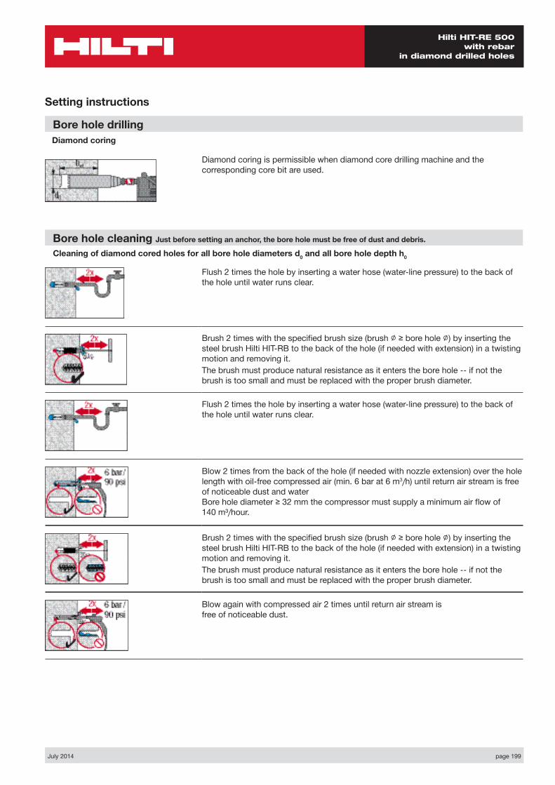
July 2014 page 199
Hilti HIT-RE 500 with rebar
in diamond drilled holes
Setting instructions
Bore hole drilling Diamond coring
Diamond coring is permissible when diamond core drilling machine and the corresponding core bit are used.
Bore hole cleaning Just before setting an anchor, the bore hole must be free of dust and debris.
Cleaning of diamond cored holes for all bore hole diameters d0 and all bore hole depth h0
Flush 2 times the hole by inserting a water hose (water-line pressure) to the back of the hole until water runs clear.
Brush 2 times with the specified brush size (brush ∅ ≥ bore hole ∅) by inserting the steel brush Hilti HIT-RB to the back of the hole (if needed with extension) in a twisting motion and removing it.The brush must produce natural resistance as it enters the bore hole -- if not the brush is too small and must be replaced with the proper brush diameter.
Flush 2 times the hole by inserting a water hose (water-line pressure) to the back of the hole until water runs clear.
Blow 2 times from the back of the hole (if needed with nozzle extension) over the hole length with oil-free compressed air (min. 6 bar at 6 m3/h) until return air stream is free of noticeable dust and water Bore hole diameter ≥ 32 mm the compressor must supply a minimum air flow of 140 m³/hour.
Brush 2 times with the specified brush size (brush ∅ ≥ bore hole ∅) by inserting the steel brush Hilti HIT-RB to the back of the hole (if needed with extension) in a twisting motion and removing it.The brush must produce natural resistance as it enters the bore hole -- if not the brush is too small and must be replaced with the proper brush diameter.
Blow again with compressed air 2 times until return air stream is free of noticeable dust.
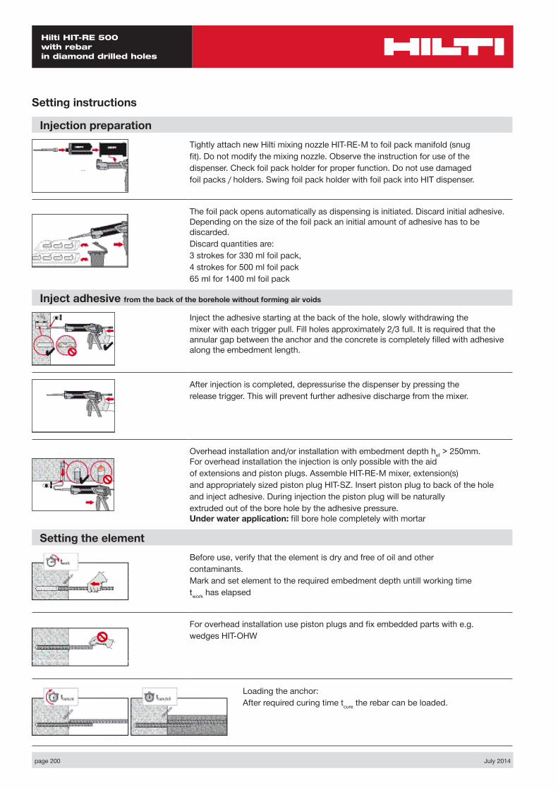
page 200 July 2014
Hilti HIT-RE 500 with rebar in diamond drilled holes
Setting instructions
Injection preparationTightly attach new Hilti mixing nozzle HIT-RE-M to foil pack manifold (snugfit). Do not modify the mixing nozzle. Observe the instruction for use of thedispenser. Check foil pack holder for proper function. Do not use damagedfoil packs / holders. Swing foil pack holder with foil pack into HIT dispenser.
The foil pack opens automatically as dispensing is initiated. Discard initial adhesive. Depending on the size of the foil pack an initial amount of adhesive has to be discarded.Discard quantities are:3 strokes for 330 ml foil pack,4 strokes for 500 ml foil pack65 ml for 1400 ml foil pack
Inject adhesive from the back of the borehole without forming air voids
Inject the adhesive starting at the back of the hole, slowly withdrawing themixer with each trigger pull. Fill holes approximately 2/3 full. It is required that the annular gap between the anchor and the concrete is completely filled with adhesive along the embedment length.
After injection is completed, depressurise the dispenser by pressing therelease trigger. This will prevent further adhesive discharge from the mixer.
Overhead installation and/or installation with embedment depth hef > 250mm. For overhead installation the injection is only possible with the aidof extensions and piston plugs. Assemble HIT-RE-M mixer, extension(s)and appropriately sized piston plug HIT-SZ. Insert piston plug to back of the holeand inject adhesive. During injection the piston plug will be naturallyextruded out of the bore hole by the adhesive pressure. Under water application: fill bore hole completely with mortar
Setting the elementBefore use, verify that the element is dry and free of oil and othercontaminants.Mark and set element to the required embedment depth untill working timetwork has elapsed
For overhead installation use piston plugs and fix embedded parts with e.g.wedges HIT-OHW
Loading the anchor:After required curing time tcure the rebar can be loaded.
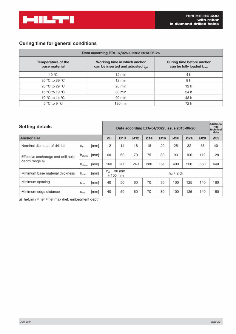
July 2014 page 201
Hilti HIT-RE 500 with rebar
in diamond drilled holes
Data according ETA-04/0027, issue 2013-06-26Additional
Hilti technical
data
Anchor size Ø8 Ø10 Ø12 Ø14 Ø16 Ø20 Ø24 Ø28 Ø32
Nominal diameter of drill bit d0 [mm] 12 14 16 18 20 25 32 35 40
Effective anchorage and drill hole depth range a)
hef,min [mm] 60 60 70 75 80 90 100 112 128
hef,max [mm] 160 200 240 280 320 400 500 560 640
Minimum base material thickness hmin [mm] hef + 30 mm ≥ 100 mm hef + 2 d0
Minimum spacing smin [mm] 40 50 60 70 80 100 125 140 160
Minimum edge distance cmin [mm] 40 50 60 70 80 100 125 140 160
a) hef,min ≤ hef ≤ hef,max (hef: embedment depth)
Setting details
Curing time for general conditions
Data according ETA-07/0260, issue 2013-06-26
Temperature of the base material
Working time in which anchor can be inserted and adjusted tgel
Curing time before anchor can be fully loaded tcure
40 °C 12 min 4 h30 °C to 39 °C 12 min 8 h20 °C to 29 °C 20 min 12 h15 °C to 19 °C 30 min 24 h10 °C to 14 °C 90 min 48 h5 °C to 9 °C 120 min 72 h
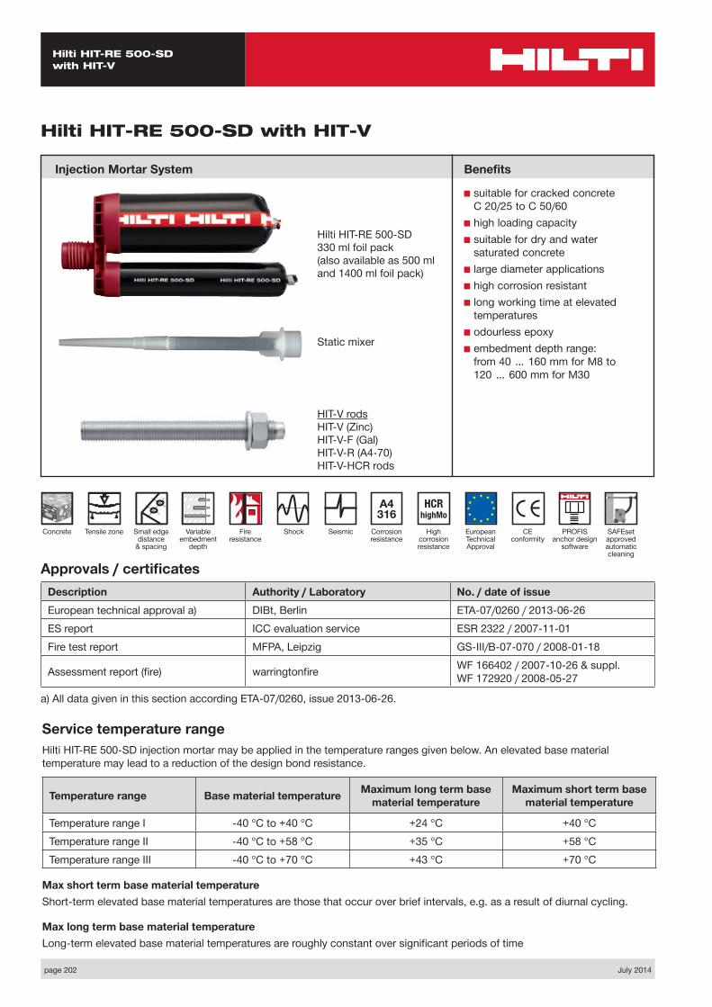
page 202 July 2014
Hilti HIT-RE 500-SD with HIT-V
Static mixer
HIT-V rodsHIT-V (Zinc)HIT-V-F (Gal)HIT-V-R (A4-70)HIT-V-HCR rods
CE conformity
Small edge distance
& spacing
European Technical Approval
Concrete
A4 316
Corrosion resistance
Shock
HCR highMo
High corrosion resistance
Seismic
Hilti HIT-RE 500-SD with HIT-V
Injection Mortar System
Variable embedment
depth
Hilti HIT-RE 500-SD 330 ml foil pack(also available as 500 ml and 1400 ml foil pack)
Approvals / certificatesDescription Authority / Laboratory No. / date of issueEuropean technical approval a) DIBt, Berlin ETA-07/0260 / 2013-06-26ES report ICC evaluation service ESR 2322 / 2007-11-01Fire test report MFPA, Leipzig GS-III/B-07-070 / 2008-01-18
Assessment report (fire) warringtonfire WF 166402 / 2007-10-26 & suppl. WF 172920 / 2008-05-27
a) All data given in this section according ETA-07/0260, issue 2013-06-26.
Service temperature rangeHilti HIT-RE 500-SD injection mortar may be applied in the temperature ranges given below. An elevated base material temperature may lead to a reduction of the design bond resistance.
Temperature range Base material temperature Maximum long term base material temperature
Maximum short term base material temperature
Temperature range I -40 °C to +40 °C +24 °C +40 °CTemperature range II -40 °C to +58 °C +35 °C +58 °CTemperature range III -40 °C to +70 °C +43 °C +70 °C
Max short term base material temperatureShort-term elevated base material temperatures are those that occur over brief intervals, e.g. as a result of diurnal cycling.
Max long term base material temperatureLong-term elevated base material temperatures are roughly constant over significant periods of time
Benefits
■ suitable for cracked concrete C 20/25 to C 50/60
■ high loading capacity■ suitable for dry and water
saturated concrete■ large diameter applications■ high corrosion resistant■ long working time at elevated
temperatures■ odourless epoxy■ embedment depth range:
from 40 … 160 mm for M8 to 120 … 600 mm for M30
Fire resistance
Tensile zone PROFIS anchor design
software
SAFEset approved automatic cleaning
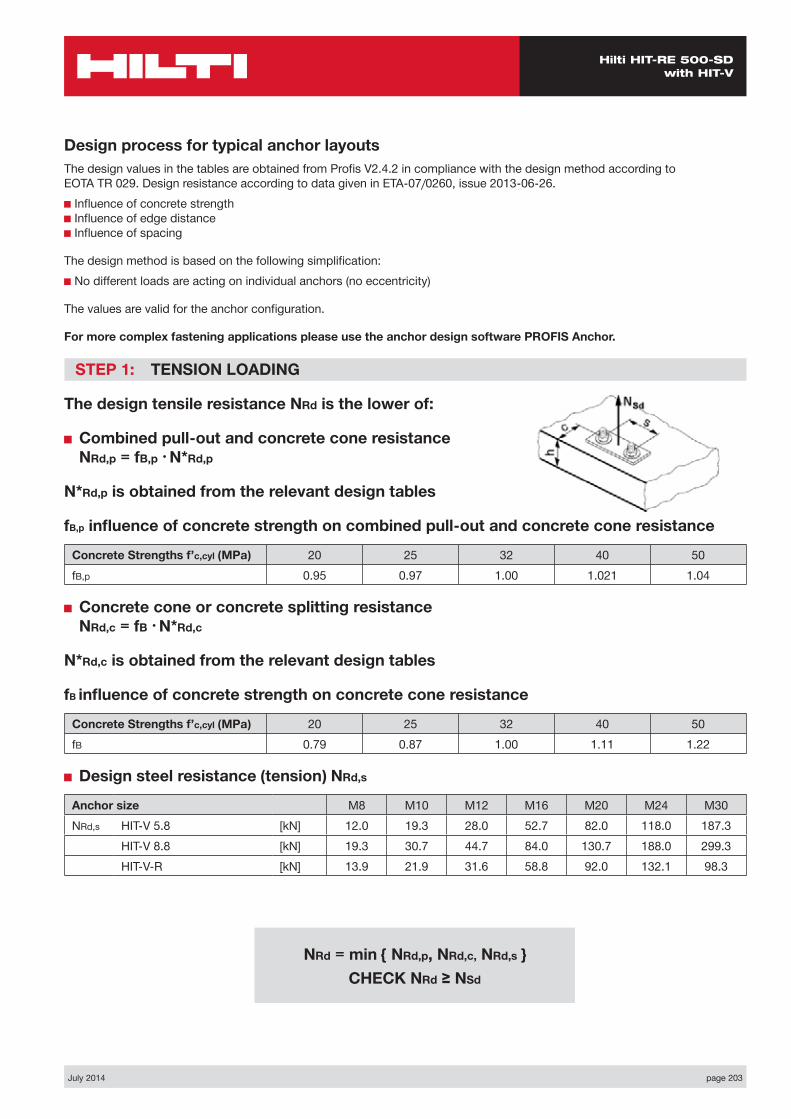
July 2014 page 203
Hilti HIT-RE 500-SD with HIT-V
Design process for typical anchor layoutsThe design values in the tables are obtained from Profis V2.4.2 in compliance with the design method according to EOTA TR 029. Design resistance according to data given in ETA-07/0260, issue 2013-06-26.■ Influence of concrete strength ■ Influence of edge distance ■ Influence of spacing
The design method is based on the following simplification:■ No different loads are acting on individual anchors (no eccentricity)
The values are valid for the anchor configuration.
For more complex fastening applications please use the anchor design software PROFIS Anchor.
STEP 1: TENSION LOADING
The design tensile resistance NRd is the lower of:
■ Combined pull-out and concrete cone resistance NRd,p = fB,p • N*Rd,p
N*Rd,p is obtained from the relevant design tables
fB,p influence of concrete strength on combined pull-out and concrete cone resistance
Concrete Strengths f’c,cyl (MPa) 20 25 32 40 50fB,p 0.95 0.97 1.00 1.021 1.04
■ Concrete cone or concrete splitting resistance NRd,c = fB • N*Rd,c
N*Rd,c is obtained from the relevant design tables
fB influence of concrete strength on concrete cone resistance
Concrete Strengths f’c,cyl (MPa) 20 25 32 40 50fB 0.79 0.87 1.00 1.11 1.22
■ Design steel resistance (tension) NRd,s
Anchor size M8 M10 M12 M16 M20 M24 M30NRd,s HIT-V 5.8 [kN] 12.0 19.3 28.0 52.7 82.0 118.0 187.3
HIT-V 8.8 [kN] 19.3 30.7 44.7 84.0 130.7 188.0 299.3HIT-V-R [kN] 13.9 21.9 31.6 58.8 92.0 132.1 98.3
NRd = min { NRd,p, NRd,c, NRd,s } CHECK NRd ≥ NSd
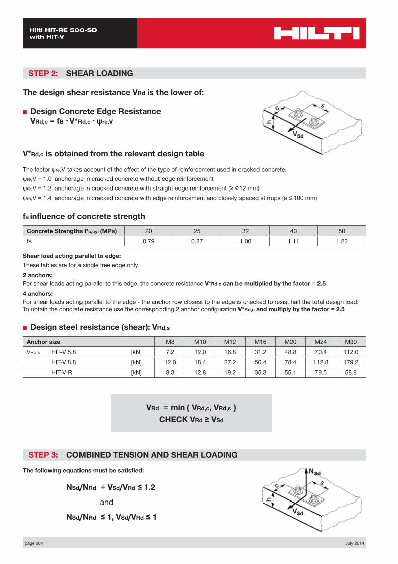
page 204 July 2014
Hilti HIT-RE 500-SD with HIT-V
STEP 2: SHEAR LOADING
The design shear resistance VRd is the lower of:
■ Design Concrete Edge Resistance VRd,c = fB • V*Rd,c • ψre,V
V*Rd,c is obtained from the relevant design table
The factor ψre,V takes account of the effect of the type of reinforcement used in cracked concrete.ψre,V = 1.0 anchorage in cracked concrete without edge reinforcementψre,V = 1.2 anchorage in cracked concrete with straight edge reinforcement (≥ ∅12 mm) ψre,V = 1.4 anchorage in cracked concrete with edge reinforcement and closely spaced stirrups (a ≤ 100 mm)
fB influence of concrete strength
Concrete Strengths f’c,cyl (MPa) 20 25 32 40 50fB 0.79 0.87 1.00 1.11 1.22
Shear load acting parallel to edge:These tables are for a single free edge only2 anchors:For shear loads acting parallel to this edge, the concrete resistance V*Rd,c can be multiplied by the factor = 2.54 anchors:For shear loads acting parallel to the edge - the anchor row closest to the edge is checked to resist half the total design load. To obtain the concrete resistance use the corresponding 2 anchor configuration V*Rd,c and multiply by the factor = 2.5
■ Design steel resistance (shear): VRd,s
Anchor size M8 M10 M12 M16 M20 M24 M30VRd,s HIT-V 5.8 [kN] 7.2 12.0 16.8 31.2 48.8 70.4 112.0
HIT-V 8.8 [kN] 12.0 18.4 27.2 50.4 78.4 112.8 179.2HIT-V-R [kN] 8.3 12.8 19.2 35.3 55.1 79.5 58.8
STEP 3: COMBINED TENSION AND SHEAR LOADING
The following equations must be satisfied:
NSd/NRd + VSd/VRd ≤ 1.2
and
NSd/NRd ≤ 1, VSd/VRd ≤ 1
VRd = min { VRd,c, VRd,s } CHECK VRd ≥ VSd
July 2014 page 205
Hilti HIT-RE 500-SD with HIT-V
Basic loading data (for a single anchor) – no edge distance and spacing influence
Embedment depth and base material thickness for the basic loading data
Anchor size M8 M10 M12 M16 M20 M24 M30
Typical embedment depth hef [mm] 80 90 110 125 170 210 270
Base material thickness h [mm] 110 120 150 200 250 300 350
Precalculated table values – design resistance values
General:The following tables provide the total ultimate limit state design resistance for the configurations. All tables are based upon:■ correct setting (See setting instruction)■ cracked concrete – fc,cyl = 32 MPa■ temperature range I (see service temperature range)■ base material thickness, as specified in the table■ One typical embedment depth, as specified in the tables■ hammer drilled hole
The following tables give design values for typical embedment depths. The latest version of the Hilti software Profis allows the engineer to optimise their design by varying the embedment depth according to the applied loads to achieve an economical solution every time. This is done by selecting HIT-V-Rods.For more information on the HIT V rods please refer to the Chemical Anchor Components & Accessories section on page 266.The anchor design software program Profis can be download from the Hilti Australia website, www.hilti.com.au.
Design resistance [kN]: dry cracked concrete, 32 Mpa
Anchor size M8 M10 M12 M16 M20 M24 M30Cracked concrete
Tensile Pull-out N*Rd,p 9.4 13.1 18.1 22.0 37.3 55.3 76.2Concrete N*Rd,c 18.1 21.6 29.2 30.3 48.1 66.0 96.2
Shear VRd,s Steel governed refer VRd,s table
Basic loading data (for a single anchor) – with minimum edge distance
Design resistance [kN] - dry cracked concrete, 32 Mpa
Anchor size M8 M10 M12 M16 M20 M24Min. edge distance cmin [mm] 40 50 60 80 100 120Min Base thickness hmin [mm] 110 120 150 200 250 300
Tensile NRd
Pull-out N*Rd,p 5.0 7.3 10.0 13.0 21.2 31.1
Concrete N*Rd,c 8.6 10.5 14.9 17.9 27.1 35.9
Shear VRd
Shear V*Rd,c (without lever arm) 3.3 4.8 6.6 10.3 15.4 21.1

page 206 July 2014
Hilti HIT-RE 500-SD with HIT-V
Nsd
Vsd
S1
C
h
Two Anchors Table 1: One edge influence – cracked concrete
Design Data: fc,cyl=32 MPa
Anchor size M8 M10 M12 M16 M20 M24Typical embedment depth hef [mm] 80 90 110 125 170 210
Base material thickness h [mm] 110 120 150 200 250 300
ANCHOR
M8Edge E (mm)
40 80 100 150 170spacings1 (mm)
tension shear tension shear tension shear tension shear tension shearN*Rd,p N*Rd,c V*Rrd,c N*Rd,p N*Rd,c V*Rrd,c N*Rd,p N*Rd,c V*Rrd,c N*Rd,p N*Rd,c V*Rrd,c N*Rd,p N*Rd,c V*Rrd,c
40 6.8 9.6 4.5 9.6 12.5 9.3 11.2 14.1 10.9 12.6 18.4 14.9 12.6 20.2 16.5
80 7.5 10.6 5.6 10.6 13.8 10.6 12.4 15.6 12.2 13.9 20.3 16.1 13.9 22.4 17.7
100 7.9 11.2 6.1 11.1 14.5 11.3 12.9 16.3 12.8 14.6 21.3 16.7 14.6 23.4 18.3
120 8.2 11.7 6.7 11.6 15.1 12.0 13.5 17.0 13.5 15.2 22.2 17.3 15.2 24.5 18.9
150 8.7 12.4 6.7 12.3 16.1 13.0 14.3 18.2 14.4 16.2 23.7 18.2 16.2 26.1 19.8
200 9.5 13.7 6.7 13.5 17.8 14.6 15.7 20.0 16.1 17.7 26.1 19.8 17.7 28.7 21.2
ANCHOR
M10Edge C (mm)
50 80 100 150 200spacings1 (mm)
tension shear tension shear tension shear tension shear tension shearN*Rd,p N*Rd,c V*Rrd,c N*Rd,p N*Rd,c V*Rrd,c N*Rd,p N*Rd,c V*Rrd,c N*Rd,p N*Rd,c V*Rrd,c N*Rd,p N*Rd,c V*Rrd,c
50 9.8 11.8 6.4 12.3 14.0 10.6 14.1 15.6 12.4 17.5 19.8 16.6 17.5 24.3 20.8
100 10.9 13.1 8.0 13.7 15.6 12.5 15.7 17.3 14.1 19.6 22.0 18.3 19.6 27.1 22.3
150 12.0 14.5 9.6 15.1 17.2 14.3 17.4 19.1 15.9 21.6 24.3 19.9 21.6 29.8 24.0
200 13.1 15.8 9.6 16.5 18.7 16.2 19.0 20.8 17.7 23.6 26.5 21.6 23.6 32.5 25.5
250 14.2 17.1 9.6 17.9 20.3 17.6 20.5 22.6 19.4 25.6 28.7 23.2 25.6 35.2 27.1
300 14.6 18.4 9.6 18.4 21.9 17.6 21.1 24.3 21.2 26.3 30.9 24.9 26.3 38.0 28.7
ANCHOR
M12Edge C (mm)
60 80 100 150 200spacings1 (mm)
tension shear tension shear tension shear tension shear tension shearN*Rd,p N*Rd,c V*Rrd,c N*Rd,p N*Rd,c V*Rrd,c N*Rd,p N*Rd,c V*Rrd,c N*Rd,p N*Rd,c V*Rrd,c N*Rd,p N*Rd,c V*Rrd,c
60 13.2 16.8 8.7 15.1 18.5 11.8 17.0 20.3 15.2 22.3 25.1 20.0 24.0 30.4 24.8
100 14.3 18.0 10.2 16.2 19.9 13.4 18.3 21.8 16.9 24.0 27.0 21.6 25.9 32.6 26.3
150 15.5 19.6 12.0 17.7 21.6 15.4 19.9 23.7 19.0 26.2 29.3 23.6 28.2 35.5 28.2
200 16.8 21.2 13.1 19.1 23.4 17.4 21.6 25.6 21.1 28.3 31.7 25.5 30.5 38.4 30.0
250 18.0 22.8 13.1 20.5 25.1 18.9 23.2 27.5 23.2 30.4 34.1 27.5 32.7 41.2 31.9
300 19.3 24.3 13.1 21.9 26.8 18.9 24.7 29.4 25.3 32.4 36.4 29.4 34.9 44.0 33.8
Tensile zone

July 2014 page 207
Hilti HIT-RE 500-SD with HIT-V
ANCHOR
M24Edge C (mm)
120 150 200 250 350spacings1 (mm)
tension shear tension shear tension shear tension shear tension shearN*Rd,p N*Rd,c V*Rrd,c N*Rd,p N*Rd,c V*Rrd,c N*Rd,p N*Rd,c V*Rrd,c N*Rd,p N*Rd,c V*Rrd,c N*Rd,p N*Rd,c V*Rrd,c
120 39.1 41.0 28.2 43.2 44.4 35.2 50.6 50.4 47.8 58.5 56.7 55.0 69.5 70.3 69.1
150 40.4 42.3 29.9 44.7 45.8 37.0 52.3 51.9 49.8 60.5 58.4 56.9 71.9 72.5 70.9
200 42.7 44.4 32.9 47.3 48.1 40.1 55.3 54.4 53.1 63.9 61.4 60.0 76.0 76.1 73.9
250 45.0 46.5 35.8 49.8 50.4 43.2 58.3 57.1 56.4 67.4 64.3 63.2 80.1 79.7 76.8
300 47.3 48.6 38.8 52.3 52.7 46.3 61.2 59.7 59.8 70.8 67.2 66.3 84.1 83.3 79.8
350 49.6 50.7 41.7 54.9 54.9 49.4 64.2 62.3 63.1 74.2 70.1 69.5 88.2 87.0 82.7
ANCHOR
M16Edge C (mm)
80 100 150 200 250spacings1 (mm)
tension shear tension shear tension shear tension shear tension shearN*Rd,p N*Rd,c V*Rrd,c N*Rd,p N*Rd,c V*Rrd,c N*Rd,p N*Rd,c V*Rrd,c N*Rd,p N*Rd,c V*Rrd,c N*Rd,p N*Rd,c V*Rrd,c
80 17.1 21.7 13.7 19.1 24.2 17.3 24.5 31.1 25.6 28.9 36.8 31.3 28.9 36.8 36.8
100 17.7 22.7 14.6 19.8 25.3 18.2 25.3 32.5 26.6 29.9 38.4 32.2 29.9 38.4 37.7
150 19.2 25.1 16.7 21.5 28.0 20.5 27.5 35.9 29.0 32.5 42.4 34.5 32.5 42.4 39.9
200 20.7 27.4 18.9 23.2 30.6 22.7 29.7 39.3 31.4 35.1 46.5 36.8 35.1 46.5 42.1
250 22.2 29.8 20.6 24.8 33.3 25.0 31.9 42.7 33.9 37.7 50.5 39.1 37.7 50.5 44.3
300 23.7 32.2 20.6 26.5 36.0 27.3 34.0 45.9 36.3 40.2 54.5 41.4 40.2 54.5 46.6
ANCHOR
M20Edge C (mm)
120 150 200 250 300spacings1 (mm)
tension shear tension shear tension shear tension shear tension shearN*Rd,p N*Rd,c V*Rrd,c N*Rd,p N*Rd,c V*Rrd,c N*Rd,p N*Rd,c V*Rrd,c N*Rd,p N*Rd,c V*Rrd,c N*Rd,p N*Rd,c V*Rrd,c
100 27.3 31.2 20.5 33.3 36.7 31.2 40.0 42.8 39.4 47.1 49.2 45.8 47.9 56.0 52.1
150 29.1 33.2 23.1 35.6 39.2 34.0 42.7 45.6 42.2 50.4 52.4 48.5 51.2 59.7 54.7
200 31.0 35.2 25.6 37.9 41.6 36.9 45.5 48.4 45.0 53.7 55.6 51.1 54.5 63.3 57.3
250 32.9 37.3 28.2 40.2 44.0 39.7 48.2 51.1 47.8 56.9 58.8 53.8 57.8 67.0 59.9
300 34.8 39.3 30.7 42.5 46.4 42.6 51.0 54.0 50.6 60.1 62.0 56.5 61.1 70.7 62.5
350 36.6 41.4 30.7 44.8 48.8 45.4 53.7 56.7 53.4 63.4 65.2 59.2 64.4 74.3 65.1
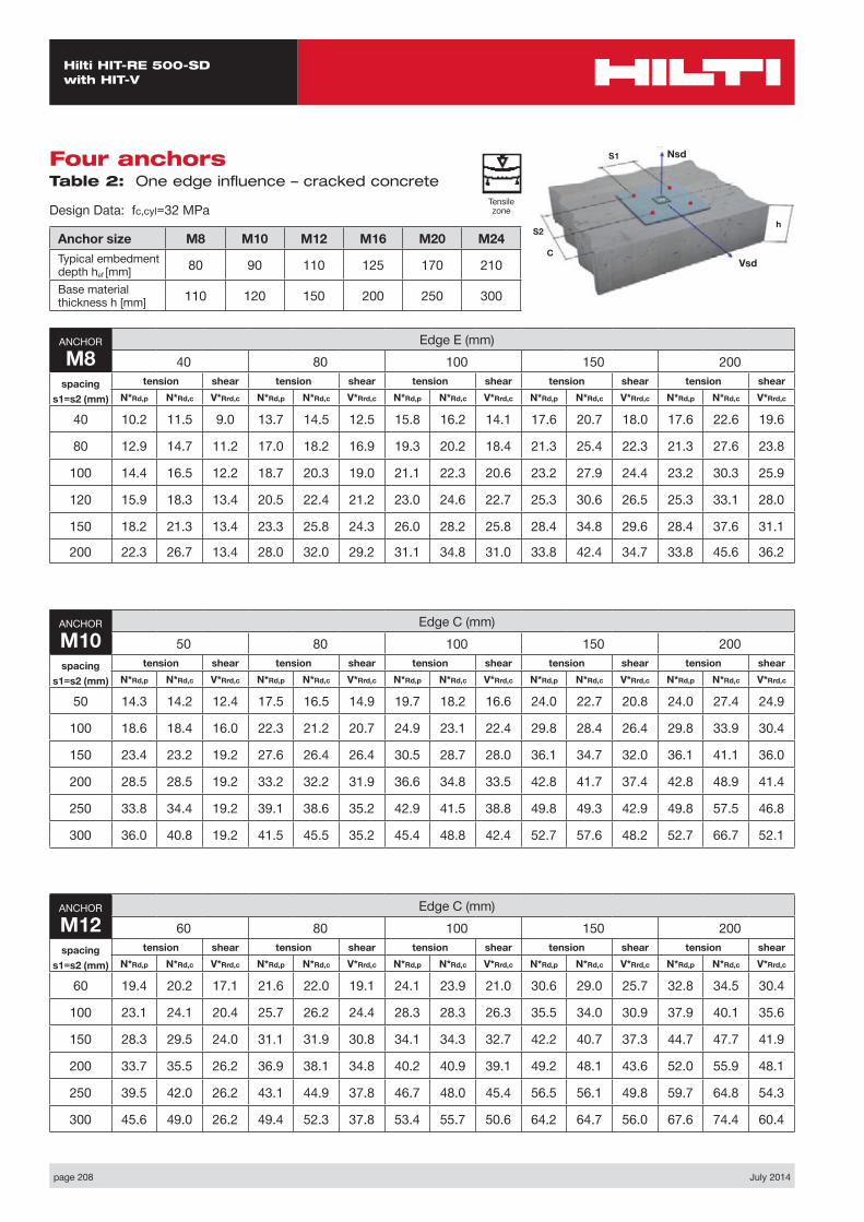
page 208 July 2014
Hilti HIT-RE 500-SD with HIT-V
Four anchors Table 2: One edge influence – cracked concrete
Design Data: fc,cyl=32 MPa
Anchor size M8 M10 M12 M16 M20 M24Typical embedment depth hef [mm] 80 90 110 125 170 210
Base material thickness h [mm] 110 120 150 200 250 300
ANCHOR
M8Edge E (mm)
40 80 100 150 200spacing
s1=s2 (mm)
tension shear tension shear tension shear tension shear tension shearN*Rd,p N*Rd,c V*Rrd,c N*Rd,p N*Rd,c V*Rrd,c N*Rd,p N*Rd,c V*Rrd,c N*Rd,p N*Rd,c V*Rrd,c N*Rd,p N*Rd,c V*Rrd,c
40 10.2 11.5 9.0 13.7 14.5 12.5 15.8 16.2 14.1 17.6 20.7 18.0 17.6 22.6 19.6
80 12.9 14.7 11.2 17.0 18.2 16.9 19.3 20.2 18.4 21.3 25.4 22.3 21.3 27.6 23.8
100 14.4 16.5 12.2 18.7 20.3 19.0 21.1 22.3 20.6 23.2 27.9 24.4 23.2 30.3 25.9
120 15.9 18.3 13.4 20.5 22.4 21.2 23.0 24.6 22.7 25.3 30.6 26.5 25.3 33.1 28.0
150 18.2 21.3 13.4 23.3 25.8 24.3 26.0 28.2 25.8 28.4 34.8 29.6 28.4 37.6 31.1
200 22.3 26.7 13.4 28.0 32.0 29.2 31.1 34.8 31.0 33.8 42.4 34.7 33.8 45.6 36.2
ANCHOR
M10Edge C (mm)
50 80 100 150 200spacing
s1=s2 (mm)
tension shear tension shear tension shear tension shear tension shearN*Rd,p N*Rd,c V*Rrd,c N*Rd,p N*Rd,c V*Rrd,c N*Rd,p N*Rd,c V*Rrd,c N*Rd,p N*Rd,c V*Rrd,c N*Rd,p N*Rd,c V*Rrd,c
50 14.3 14.2 12.4 17.5 16.5 14.9 19.7 18.2 16.6 24.0 22.7 20.8 24.0 27.4 24.9
100 18.6 18.4 16.0 22.3 21.2 20.7 24.9 23.1 22.4 29.8 28.4 26.4 29.8 33.9 30.4
150 23.4 23.2 19.2 27.6 26.4 26.4 30.5 28.7 28.0 36.1 34.7 32.0 36.1 41.1 36.0
200 28.5 28.5 19.2 33.2 32.2 31.9 36.6 34.8 33.5 42.8 41.7 37.4 42.8 48.9 41.4
250 33.8 34.4 19.2 39.1 38.6 35.2 42.9 41.5 38.8 49.8 49.3 42.9 49.8 57.5 46.8
300 36.0 40.8 19.2 41.5 45.5 35.2 45.4 48.8 42.4 52.7 57.6 48.2 52.7 66.7 52.1
ANCHOR
M12Edge C (mm)
60 80 100 150 200spacing
s1=s2 (mm)
tension shear tension shear tension shear tension shear tension shearN*Rd,p N*Rd,c V*Rrd,c N*Rd,p N*Rd,c V*Rrd,c N*Rd,p N*Rd,c V*Rrd,c N*Rd,p N*Rd,c V*Rrd,c N*Rd,p N*Rd,c V*Rrd,c
60 19.4 20.2 17.1 21.6 22.0 19.1 24.1 23.9 21.0 30.6 29.0 25.7 32.8 34.5 30.4
100 23.1 24.1 20.4 25.7 26.2 24.4 28.3 28.3 26.3 35.5 34.0 30.9 37.9 40.1 35.6
150 28.3 29.5 24.0 31.1 31.9 30.8 34.1 34.3 32.7 42.2 40.7 37.3 44.7 47.7 41.9
200 33.7 35.5 26.2 36.9 38.1 34.8 40.2 40.9 39.1 49.2 48.1 43.6 52.0 55.9 48.1
250 39.5 42.0 26.2 43.1 44.9 37.8 46.7 48.0 45.4 56.5 56.1 49.8 59.7 64.8 54.3
300 45.6 49.0 26.2 49.4 52.3 37.8 53.4 55.7 50.6 64.2 64.7 56.0 67.6 74.4 60.4
Nsd
Vsd
S2
S1
C
h
Tensile zone
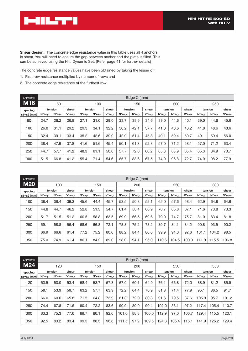
July 2014 page 209
Hilti HIT-RE 500-SD with HIT-V
ANCHOR
M24Edge C (mm)
120 150 200 250 350spacing
s1=s2 (mm)
tension shear tension shear tension shear tension shear tension shearN*Rd,p N*Rd,c V*Rrd,c N*Rd,p N*Rd,c V*Rrd,c N*Rd,p N*Rd,c V*Rrd,c N*Rd,p N*Rd,c V*Rrd,c N*Rd,p N*Rd,c V*Rrd,c
120 53.5 50.0 53.4 58.4 53.7 57.8 67.0 60.1 64.9 76.1 66.8 72.0 88.9 81.2 85.9
150 58.1 53.9 59.7 63.2 57.7 63.9 72.2 64.4 70.9 81.8 71.4 77.9 95.1 86.5 91.7
200 66.0 60.6 65.8 71.5 64.8 73.9 81.3 72.0 80.8 91.6 79.5 87.6 105.9 95.7 101.2
250 74.4 67.8 71.6 80.4 72.2 83.6 90.9 80.0 90.4 102.0 88.1 97.2 117.4 105.4 110.7
300 83.3 75.3 77.6 89.7 80.1 92.6 101.0 88.3 100.0 112.9 97.0 106.7 129.4 115.5 120.1
350 92.5 83.2 83.4 99.5 88.3 98.8 111.5 97.2 109.5 124.3 106.4 116.1 141.9 126.2 129.4
ANCHOR
M16Edge C (mm)
80 100 150 200 250spacing
s1=s2 (mm)
tension shear tension shear tension shear tension shear tension shearN*Rd,p N*Rd,c V*Rrd,c N*Rd,p N*Rd,c V*Rrd,c N*Rd,p N*Rd,c V*Rrd,c N*Rd,p N*Rd,c V*Rrd,c N*Rd,p N*Rd,c V*Rrd,c
80 24.7 28.2 26.8 27.1 31.0 29.0 33.7 38.5 34.6 39.0 44.6 40.1 39.0 44.6 45.6
100 26.8 31.1 29.2 29.3 34.1 32.2 36.2 42.1 37.7 41.8 48.6 43.2 41.8 48.6 48.6
150 32.4 39.1 33.4 35.2 42.6 39.9 42.9 51.4 45.3 49.1 59.4 50.7 49.1 59.4 56.0
200 38.4 47.9 37.8 41.6 51.6 45.4 50.1 61.3 52.8 57.0 71.2 58.1 57.0 71.2 63.4
250 44.7 57.7 41.2 48.3 61.1 50.0 57.7 72.0 60.2 65.3 83.9 65.4 65.3 84.9 70.7
300 51.5 66.8 41.2 55.4 71.4 54.6 65.7 83.6 67.5 74.0 96.8 72.7 74.0 98.2 77.9
ANCHOR
M20Edge C (mm)
100 150 200 250 300spacing
s1=s2 (mm)
tension shear tension shear tension shear tension shear tension shearN*Rd,p N*Rd,c V*Rrd,c N*Rd,p N*Rd,c V*Rrd,c N*Rd,p N*Rd,c V*Rrd,c N*Rd,p N*Rd,c V*Rrd,c N*Rd,p N*Rd,c V*Rrd,c
100 38.4 38.4 39.3 45.6 44.4 45.7 53.5 50.8 52.1 62.0 57.6 58.4 62.9 64.8 64.6
150 44.8 44.7 46.2 52.8 51.3 54.7 61.4 58.4 60.9 70.7 65.8 67.1 71.6 73.8 73.3
200 51.7 51.5 51.2 60.5 58.8 63.5 69.9 66.5 69.6 79.9 74.7 75.7 81.0 83.4 81.8
250 59.1 58.8 56.4 68.6 66.8 72.1 78.8 75.2 78.2 89.7 84.1 84.2 90.8 93.5 90.2
300 66.9 66.6 61.4 77.2 75.2 80.6 88.2 84.4 86.6 99.9 94.0 92.6 101.1 104.2 98.5
350 75.0 74.9 61.4 86.1 84.2 89.0 98.0 94.1 95.0 110.6 104.5 100.9 111.9 115.5 106.8
Shear design: The concrete edge resistance value in this table uses all 4 anchors in shear. You will need to ensure the gap between anchor and the plate is filled. This can be achieved using the Hilti Dynamic Set. (Refer page 41 for further details)
The concrete edge resistance values have been obtained by taking the lesser of:1. First row resistance multiplied by number of rows and 2. The concrete edge resistance of the furthest row.
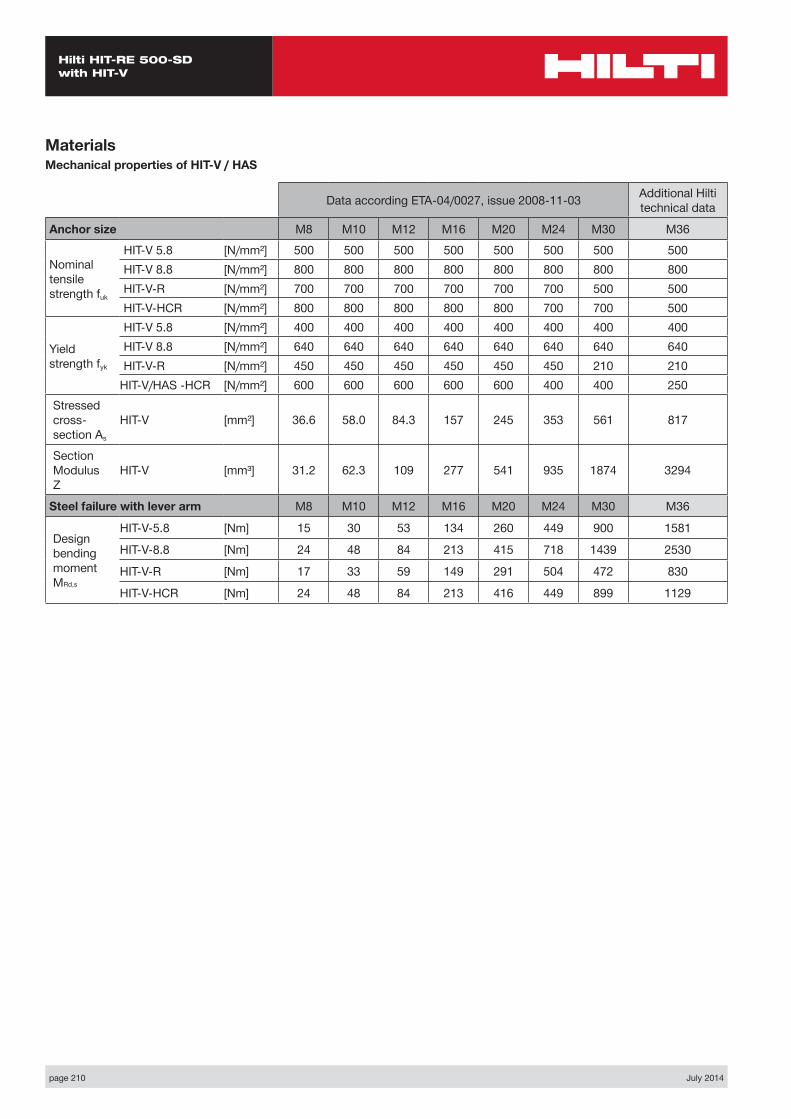
page 210 July 2014
Hilti HIT-RE 500-SD with HIT-V
MaterialsMechanical properties of HIT-V / HAS
Data according ETA-04/0027, issue 2008-11-03 Additional Hilti technical data
Anchor size M8 M10 M12 M16 M20 M24 M30 M36
Nominal tensile strength fuk
HIT-V 5.8 [N/mm²] 500 500 500 500 500 500 500 500HIT-V 8.8 [N/mm²] 800 800 800 800 800 800 800 800HIT-V-R [N/mm²] 700 700 700 700 700 700 500 500HIT-V-HCR [N/mm²] 800 800 800 800 800 700 700 500
Yield strength fyk
HIT-V 5.8 [N/mm²] 400 400 400 400 400 400 400 400HIT-V 8.8 [N/mm²] 640 640 640 640 640 640 640 640HIT-V-R [N/mm²] 450 450 450 450 450 450 210 210
HIT-V/HAS -HCR [N/mm²] 600 600 600 600 600 400 400 250Stressed cross- section As
HIT-V [mm²] 36.6 58.0 84.3 157 245 353 561 817
Section Modulus Z
HIT-V [mm³] 31.2 62.3 109 277 541 935 1874 3294
Steel failure with lever arm M8 M10 M12 M16 M20 M24 M30 M36
Design bending moment MRd,s
HIT-V-5.8 [Nm] 15 30 53 134 260 449 900 1581
HIT-V-8.8 [Nm] 24 48 84 213 415 718 1439 2530
HIT-V-R [Nm] 17 33 59 149 291 504 472 830
HIT-V-HCR [Nm] 24 48 84 213 416 449 899 1129
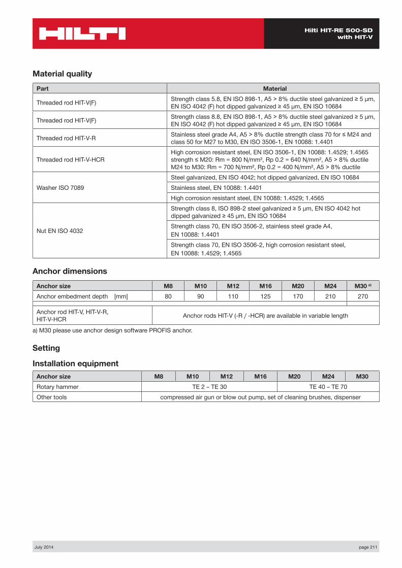
July 2014 page 211
Hilti HIT-RE 500-SD with HIT-V
Material quality
Part Material
Threaded rod HIT-V(F) Strength class 5.8, EN ISO 898-1, A5 > 8% ductile steel galvanized ≥ 5 µm, EN ISO 4042 (F) hot dipped galvanized ≥ 45 µm, EN ISO 10684
Threaded rod HIT-V(F) Strength class 8.8, EN ISO 898-1, A5 > 8% ductile steel galvanized ≥ 5 µm, EN ISO 4042 (F) hot dipped galvanized ≥ 45 µm, EN ISO 10684
Threaded rod HIT-V-R Stainless steel grade A4, A5 > 8% ductile strength class 70 for ≤ M24 and class 50 for M27 to M30, EN ISO 3506-1, EN 10088: 1.4401
Threaded rod HIT-V-HCRHigh corrosion resistant steel, EN ISO 3506-1, EN 10088: 1.4529; 1.4565 strength ≤ M20: Rm = 800 N/mm², Rp 0.2 = 640 N/mm², A5 > 8% ductile M24 to M30: Rm = 700 N/mm², Rp 0.2 = 400 N/mm², A5 > 8% ductile
Washer ISO 7089Steel galvanized, EN ISO 4042; hot dipped galvanized, EN ISO 10684Stainless steel, EN 10088: 1.4401High corrosion resistant steel, EN 10088: 1.4529; 1.4565
Nut EN ISO 4032
Strength class 8, ISO 898-2 steel galvanized ≥ 5 µm, EN ISO 4042 hot dipped galvanized ≥ 45 µm, EN ISO 10684Strength class 70, EN ISO 3506-2, stainless steel grade A4,EN 10088: 1.4401Strength class 70, EN ISO 3506-2, high corrosion resistant steel,EN 10088: 1.4529; 1.4565
Anchor dimensions
Anchor size M8 M10 M12 M16 M20 M24 M30 a)
Anchor embedment depth [mm] 80 90 110 125 170 210 270
Anchor rod HIT-V, HIT-V-R, HIT-V-HCR Anchor rods HIT-V (-R / -HCR) are available in variable length
a) M30 please use anchor design software PROFIS anchor.
Setting
Installation equipmentAnchor size M8 M10 M12 M16 M20 M24 M30Rotary hammer TE 2 – TE 30 TE 40 – TE 70Other tools compressed air gun or blow out pump, set of cleaning brushes, dispenser
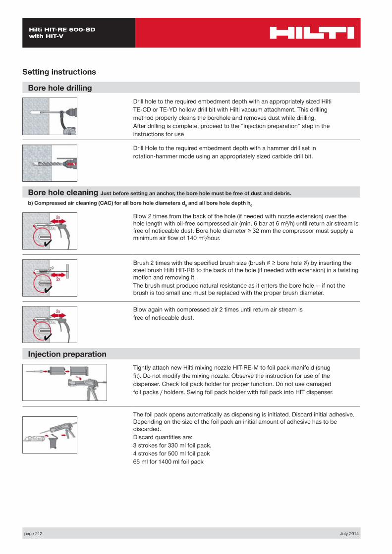
page 212 July 2014
Hilti HIT-RE 500-SD with HIT-V
Setting instructions
Bore hole drillingDrill hole to the required embedment depth with an appropriately sized HiltiTE-CD or TE-YD hollow drill bit with Hilti vacuum attachment. This drillingmethod properly cleans the borehole and removes dust while drilling.After drilling is complete, proceed to the “injection preparation” step in theinstructions for use
Drill Hole to the required embedment depth with a hammer drill set inrotation-hammer mode using an appropriately sized carbide drill bit.
Bore hole cleaning Just before setting an anchor, the bore hole must be free of dust and debris.
b) Compressed air cleaning (CAC) for all bore hole diameters d0 and all bore hole depth h0
Blow 2 times from the back of the hole (if needed with nozzle extension) over the hole length with oil-free compressed air (min. 6 bar at 6 m³/h) until return air stream is free of noticeable dust. Bore hole diameter ≥ 32 mm the compressor must supply a minimum air flow of 140 m³/hour.
Brush 2 times with the specified brush size (brush ∅ ≥ bore hole ∅) by inserting the steel brush Hilti HIT-RB to the back of the hole (if needed with extension) in a twisting motion and removing it.The brush must produce natural resistance as it enters the bore hole -- if not the brush is too small and must be replaced with the proper brush diameter.
Blow again with compressed air 2 times until return air stream isfree of noticeable dust.
Injection preparationTightly attach new Hilti mixing nozzle HIT-RE-M to foil pack manifold (snugfit). Do not modify the mixing nozzle. Observe the instruction for use of thedispenser. Check foil pack holder for proper function. Do not use damagedfoil packs / holders. Swing foil pack holder with foil pack into HIT dispenser.
The foil pack opens automatically as dispensing is initiated. Discard initial adhesive. Depending on the size of the foil pack an initial amount of adhesive has to be discarded.Discard quantities are:3 strokes for 330 ml foil pack,4 strokes for 500 ml foil pack65 ml for 1400 ml foil pack
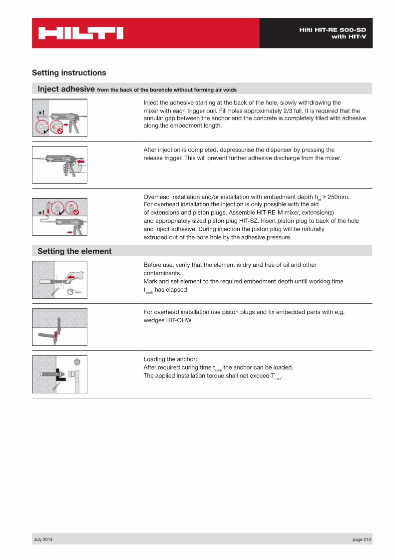
July 2014 page 213
Hilti HIT-RE 500-SD with HIT-V
Setting instructions
Inject adhesive from the back of the borehole without forming air voids
Inject the adhesive starting at the back of the hole, slowly withdrawing themixer with each trigger pull. Fill holes approximately 2/3 full. It is required that the annular gap between the anchor and the concrete is completely filled with adhesive along the embedment length.
After injection is completed, depressurise the dispenser by pressing therelease trigger. This will prevent further adhesive discharge from the mixer.
Overhead installation and/or installation with embedment depth hef > 250mm. For overhead installation the injection is only possible with the aidof extensions and piston plugs. Assemble HIT-RE-M mixer, extension(s)and appropriately sized piston plug HIT-SZ. Insert piston plug to back of the holeand inject adhesive. During injection the piston plug will be naturallyextruded out of the bore hole by the adhesive pressure.
Setting the elementBefore use, verify that the element is dry and free of oil and othercontaminants.Mark and set element to the required embedment depth untill working timetwork has elapsed
For overhead installation use piston plugs and fix embedded parts with e.g.wedges HIT-OHW
Loading the anchor:After required curing time tcure the anchor can be loaded.The applied installation torque shall not exceed Tmax.
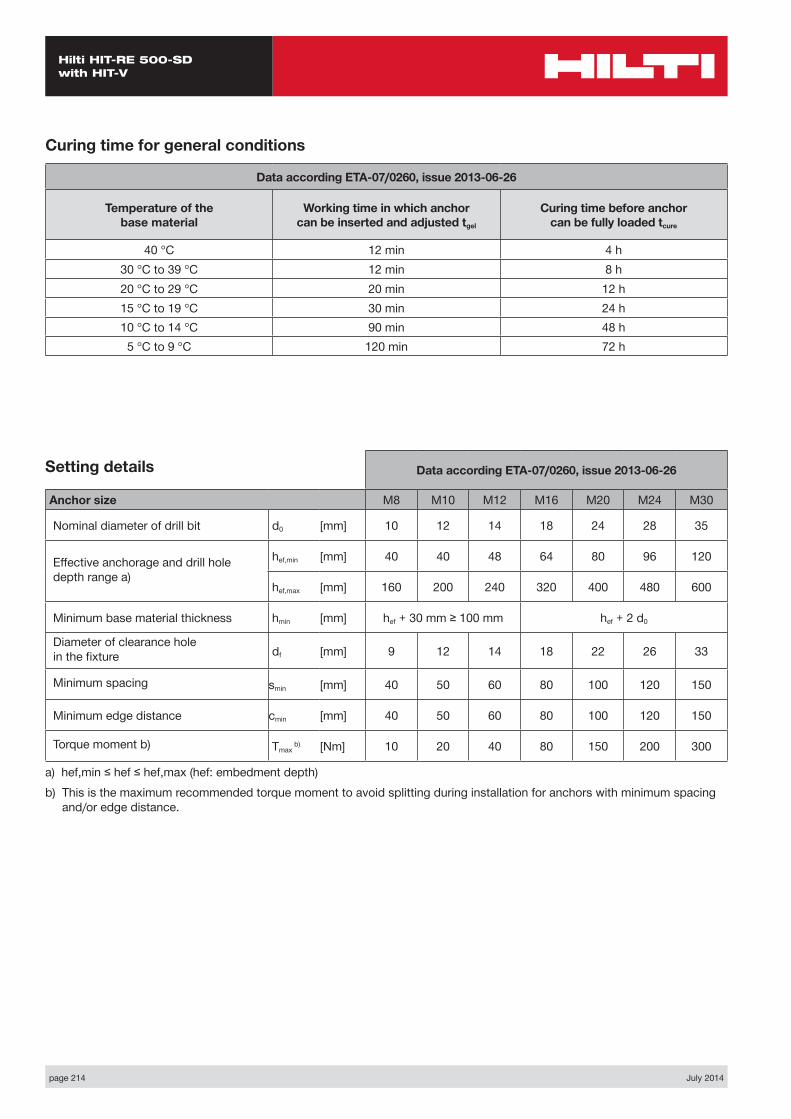
page 214 July 2014
Hilti HIT-RE 500-SD with HIT-V
Data according ETA-07/0260, issue 2013-06-26
Anchor size M8 M10 M12 M16 M20 M24 M30
Nominal diameter of drill bit d0 [mm] 10 12 14 18 24 28 35
Effective anchorage and drill hole depth range a)
hef,min [mm] 40 40 48 64 80 96 120
hef,max [mm] 160 200 240 320 400 480 600
Minimum base material thickness hmin [mm] hef + 30 mm ≥ 100 mm hef + 2 d0
Diameter of clearance hole in the fixture df [mm] 9 12 14 18 22 26 33
Minimum spacing smin [mm] 40 50 60 80 100 120 150
Minimum edge distance cmin [mm] 40 50 60 80 100 120 150
Torque moment b) Tmax b) [Nm] 10 20 40 80 150 200 300
a) hef,min ≤ hef ≤ hef,max (hef: embedment depth)b) This is the maximum recommended torque moment to avoid splitting during installation for anchors with minimum spacing
and/or edge distance.
Setting details
Curing time for general conditions
Data according ETA-07/0260, issue 2013-06-26
Temperature of the base material
Working time in which anchor can be inserted and adjusted tgel
Curing time before anchor can be fully loaded tcure
40 °C 12 min 4 h30 °C to 39 °C 12 min 8 h20 °C to 29 °C 20 min 12 h15 °C to 19 °C 30 min 24 h10 °C to 14 °C 90 min 48 h5 °C to 9 °C 120 min 72 h
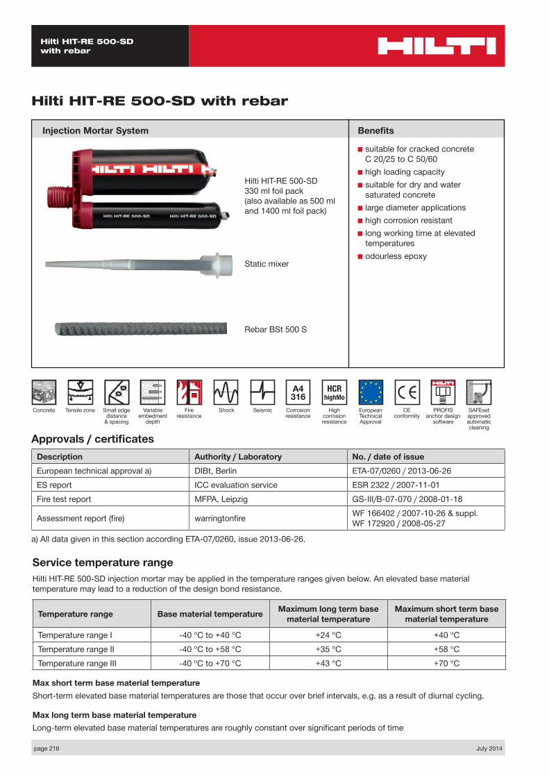
page 216 July 2014
Hilti HIT-RE 500-SD with rebar
Static mixer
CE conformity
Small edge distance
& spacing
European Technical Approval
Concrete
A4 316
Corrosion resistance
Shock
HCR highMo
High corrosion resistance
Seismic
Hilti HIT-RE 500-SD with rebar
Injection Mortar System
Variable embedment
depth
Hilti HIT-RE 500-SD 330 ml foil pack(also available as 500 ml and 1400 ml foil pack)
Approvals / certificatesDescription Authority / Laboratory No. / date of issueEuropean technical approval a) DIBt, Berlin ETA-07/0260 / 2013-06-26ES report ICC evaluation service ESR 2322 / 2007-11-01Fire test report MFPA, Leipzig GS-III/B-07-070 / 2008-01-18
Assessment report (fire) warringtonfire WF 166402 / 2007-10-26 & suppl. WF 172920 / 2008-05-27
a) All data given in this section according ETA-07/0260, issue 2013-06-26.
Service temperature rangeHilti HIT-RE 500-SD injection mortar may be applied in the temperature ranges given below. An elevated base material temperature may lead to a reduction of the design bond resistance.
Temperature range Base material temperature Maximum long term base material temperature
Maximum short term base material temperature
Temperature range I -40 °C to +40 °C +24 °C +40 °CTemperature range II -40 °C to +58 °C +35 °C +58 °CTemperature range III -40 °C to +70 °C +43 °C +70 °C
Max short term base material temperatureShort-term elevated base material temperatures are those that occur over brief intervals, e.g. as a result of diurnal cycling.
Max long term base material temperatureLong-term elevated base material temperatures are roughly constant over significant periods of time
Benefits
■ suitable for cracked concrete C 20/25 to C 50/60
■ high loading capacity■ suitable for dry and water
saturated concrete■ large diameter applications■ high corrosion resistant■ long working time at elevated
temperatures■ odourless epoxy
Fire resistance
Tensile zone PROFIS anchor design
software
Rebar BSt 500 S
SAFEset approved automatic cleaning

July 2014 page 217
Hilti HIT-RE 500-SD with rebar
Design process for typical anchor layoutsThe design values in the tables are obtained from Profis V2.4.2 in compliance with the design method according to EOTA TR 029. Design resistance according to data given in ETA-07/0260, issue 2013-06-26.■ Influence of concrete strength ■ Influence of edge distance ■ Influence of spacing
The design method is based on the following simplification:■ No different loads are acting on individual anchors (no eccentricity)
The values are valid for the anchor configuration.
For more complex fastening applications please use the anchor design software PROFIS Anchor.
STEP 1: TENSION LOADING
The design tensile resistance NRd is the lower of:
■ Combined pull-out and concrete cone resistance NRd,p = fB,p • N*Rd,p
N*Rd,p is obtained from the relevant design tables
fB,p influence of concrete strength on combined pull-out and concrete cone resistance
Concrete Strengths f’c,cyl (MPa) 20 25 32 40 50fB,p 0.95 0.97 1.00 1.02 1.04
■ Concrete cone or concrete splitting resistance NRd,c = fB • N*Rd,c
N*Rd,c is obtained from the relevant design tables
fB influence of concrete strength on concrete cone resistance
Concrete Strengths f’c,cyl (MPa) 20 25 32 40 50fB 0.79 0.87 1.00 1.11 1.22
■ Design steel resistance NRd,s
Anchor size Ø8 Ø10 Ø12 Ø14 Ø16 Ø20 Ø24 Ø28 Ø32NRd,s BSt 500 S [kN] 20.0 30.7 44.3 60.7 79.3 123.6 177.8 242.1 315.7
NRd = min { NRd,p, NRd,c, NRd,s } CHECK NRd ≥ NSd
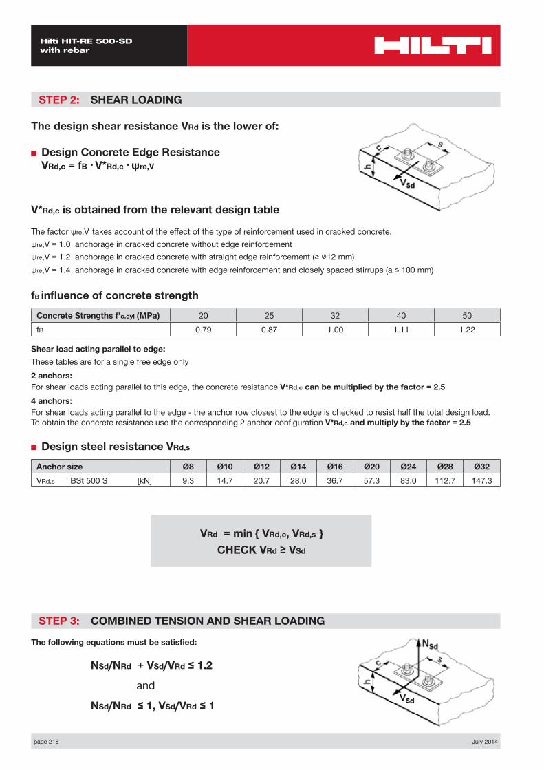
page 218 July 2014
Hilti HIT-RE 500-SD with rebar
STEP 2: SHEAR LOADING
The design shear resistance VRd is the lower of:
■ Design Concrete Edge Resistance VRd,c = fB • V*Rd,c • ψre,V
V*Rd,c is obtained from the relevant design table
The factor ψre,V takes account of the effect of the type of reinforcement used in cracked concrete.ψre,V = 1.0 anchorage in cracked concrete without edge reinforcementψre,V = 1.2 anchorage in cracked concrete with straight edge reinforcement (≥ ∅12 mm) ψre,V = 1.4 anchorage in cracked concrete with edge reinforcement and closely spaced stirrups (a ≤ 100 mm)
fB influence of concrete strength
Concrete Strengths f’c,cyl (MPa) 20 25 32 40 50fB 0.79 0.87 1.00 1.11 1.22
Shear load acting parallel to edge:These tables are for a single free edge only2 anchors:For shear loads acting parallel to this edge, the concrete resistance V*Rd,c can be multiplied by the factor = 2.54 anchors:For shear loads acting parallel to the edge - the anchor row closest to the edge is checked to resist half the total design load. To obtain the concrete resistance use the corresponding 2 anchor configuration V*Rd,c and multiply by the factor = 2.5
■ Design steel resistance VRd,s
Anchor size Ø8 Ø10 Ø12 Ø14 Ø16 Ø20 Ø24 Ø28 Ø32VRd,s BSt 500 S [kN] 9.3 14.7 20.7 28.0 36.7 57.3 83.0 112.7 147.3
STEP 3: COMBINED TENSION AND SHEAR LOADING
The following equations must be satisfied:
NSd/NRd + VSd/VRd ≤ 1.2
and
NSd/NRd ≤ 1, VSd/VRd ≤ 1
VRd = min { VRd,c, VRd,s } CHECK VRd ≥ VSd
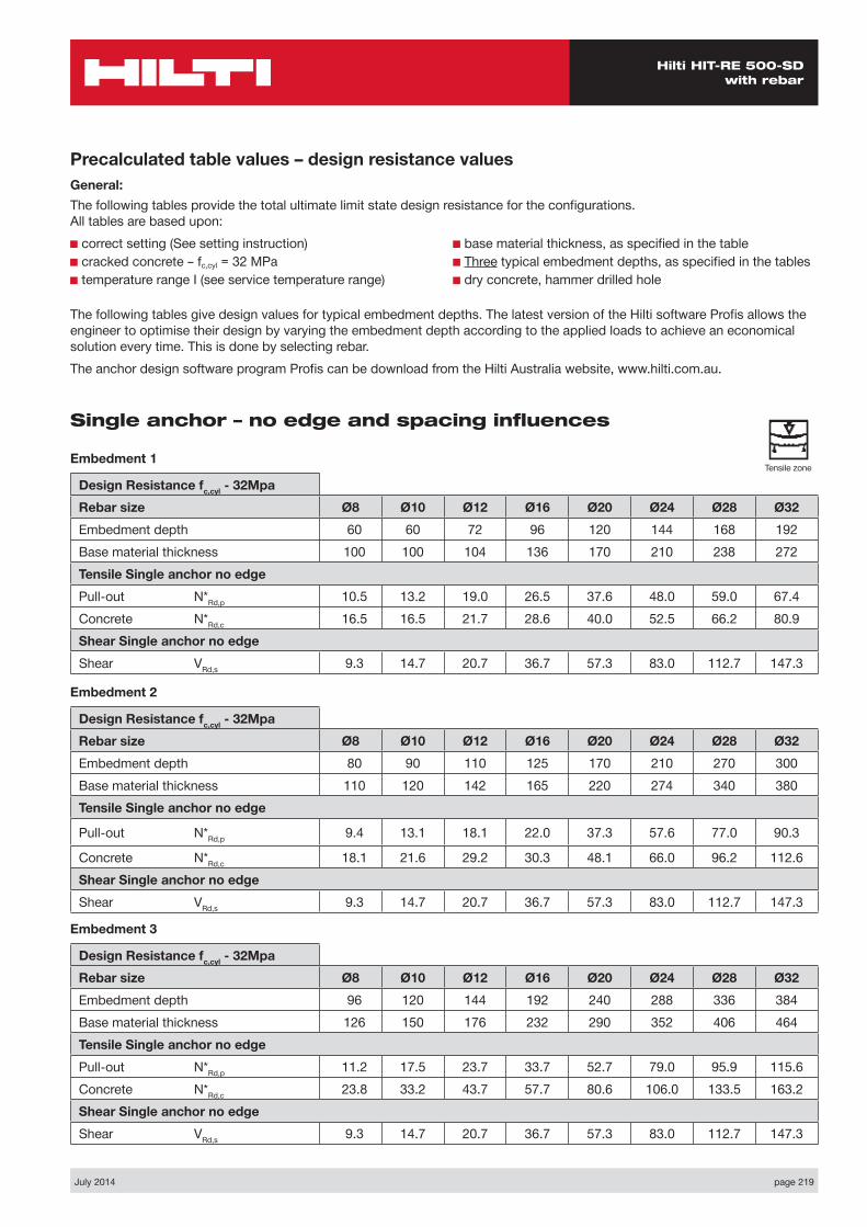
July 2014 page 219
Hilti HIT-RE 500-SD with rebar
Precalculated table values – design resistance valuesGeneral:The following tables provide the total ultimate limit state design resistance for the configurations. All tables are based upon:■ correct setting (See setting instruction)■ cracked concrete – fc,cyl = 32 MPa■ temperature range I (see service temperature range)
■ base material thickness, as specified in the table■ Three typical embedment depths, as specified in the tables■ dry concrete, hammer drilled hole
The following tables give design values for typical embedment depths. The latest version of the Hilti software Profis allows the engineer to optimise their design by varying the embedment depth according to the applied loads to achieve an economical solution every time. This is done by selecting rebar.The anchor design software program Profis can be download from the Hilti Australia website, www.hilti.com.au.
Single anchor – no edge and spacing influences
Embedment 1
Design Resistance fc,cyl - 32MpaRebar size Ø8 Ø10 Ø12 Ø16 Ø20 Ø24 Ø28 Ø32Embedment depth 60 60 72 96 120 144 168 192Base material thickness 100 100 104 136 170 210 238 272Tensile Single anchor no edgePull-out N*Rd,p 10.5 13.2 19.0 26.5 37.6 48.0 59.0 67.4Concrete N*Rd,c 16.5 16.5 21.7 28.6 40.0 52.5 66.2 80.9Shear Single anchor no edge Shear VRd,s 9.3 14.7 20.7 36.7 57.3 83.0 112.7 147.3
Embedment 2
Design Resistance fc,cyl - 32MpaRebar size Ø8 Ø10 Ø12 Ø16 Ø20 Ø24 Ø28 Ø32Embedment depth 80 90 110 125 170 210 270 300Base material thickness 110 120 142 165 220 274 340 380Tensile Single anchor no edge
Pull-out N*Rd,p 9.4 13.1 18.1 22.0 37.3 57.6 77.0 90.3
Concrete N*Rd,c 18.1 21.6 29.2 30.3 48.1 66.0 96.2 112.6Shear Single anchor no edge Shear VRd,s 9.3 14.7 20.7 36.7 57.3 83.0 112.7 147.3
Embedment 3
Design Resistance fc,cyl - 32MpaRebar size Ø8 Ø10 Ø12 Ø16 Ø20 Ø24 Ø28 Ø32Embedment depth 96 120 144 192 240 288 336 384Base material thickness 126 150 176 232 290 352 406 464Tensile Single anchor no edgePull-out N*Rd,p 11.2 17.5 23.7 33.7 52.7 79.0 95.9 115.6Concrete N*Rd,c 23.8 33.2 43.7 57.7 80.6 106.0 133.5 163.2Shear Single anchor no edge Shear VRd,s 9.3 14.7 20.7 36.7 57.3 83.0 112.7 147.3
Tensile zone

page 220 July 2014
Hilti HIT-RE 500-SD with rebar
Single anchor – minimum edge distance
Embedment 1
Design Resistance fc,cyl - 32MpaRebar size Ø8 Ø10 Ø12 Ø16 Ø20 Ø24 Ø28 Ø32Embedment depth 60 60 72 96 120 144 168 192Base material thickness 100 100 104 136 170 210 238 272Edge Dist c= cmin 40 50 60 80 100 120 140 160Tensile Single anchor min edge
Pull-out N*Rd,p 4.2 5.9 8.0 11.4 17.8 27.2 32.5 39.0Concrete N*Rd,c 6.9 7.7 9.0 11.8 16.5 22.6 27.3 33.3
Shear Single anchor min edge
Shear V*Rd,c (without lever arm) 3.1 4.4 6.0 9.7 14.1 20.3 24.8 31.0
Embedment 2
Design Resistance fc,cyl - 32MpaRebar size Ø8 Ø10 Ø12 Ø16 Ø20 Ø24 Ø28 Ø32Embedment depth 80 90 110 125 170 210 270 300Base material thickness 110 120 142 165 220 270 340 380Edge Dist c= cmin 40 50 60 80 100 125 140 160Tensile Single anchor min edge
Pull-out N*Rd,p 5.1 7.3 10.0 13.0 21.2 33.0 43.3 50.7Concrete N*Rd,c 8.6 10.5 14.0 15.3 23.6 32.5 45.5 53.7
Shear Single anchor min edge
Shear V*Rd,c (without lever arm) 3.3 4.8 6.6 10.3 15.4 22.4 28.3 35.3
Embedment 3
Design Resistance fc,cyl - 32MpaRebar size Ø8 Ø10 Ø12 Ø16 Ø20 Ø24 Ø28 Ø32Embedment depth 96 120 144 192 240 288 336 384Base material thickness 126 150 176 232 290 348 406 464Edge Dist c= cmin 40 50 60 80 100 125 140 160Tensile Single anchor min edge
Pull-out N*Rd,p 6.1 9.6 12.9 18.6 29.1 44.4 53.8 64.9Concrete N*Rd,c 10.7 14.9 19.6 25.8 36.1 47.9 59.7 73.0
Shear Single anchor min edge
Shear V*Rd,c (without lever arm) 3.5 5.1 7.0 11.5 17.0 24.6 30.3 38.2
Tensile zone
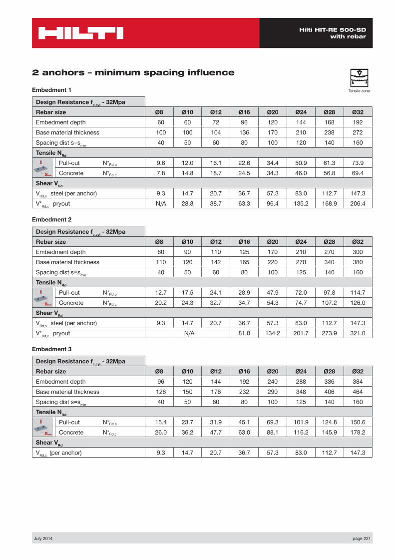
July 2014 page 221
Hilti HIT-RE 500-SD with rebar
2 anchors – minimum spacing influence
Embedment 1
Design Resistance fc,cyl - 32MpaRebar size Ø8 Ø10 Ø12 Ø16 Ø20 Ø24 Ø28 Ø32Embedment depth 60 60 72 96 120 144 168 192Base material thickness 100 100 104 136 170 210 238 272Spacing dist s=smin 40 50 60 80 100 120 140 160Tensile NRd
Pull-out N*Rd,p 9.6 12.0 16.1 22.6 34.4 50.9 61.3 73.9Concrete N*Rd,c 7.8 14.8 18.7 24.5 34.3 46.0 56.8 69.4
Shear VRd VRd,s steel (per anchor) 9.3 14.7 20.7 36.7 57.3 83.0 112.7 147.3V*Rd,c pryout N/A 28.8 38.7 63.3 96.4 135.2 168.9 206.4
Embedment 2
Design Resistance fc,cyl - 32MpaRebar size Ø8 Ø10 Ø12 Ø16 Ø20 Ø24 Ø28 Ø32Embedment depth 80 90 110 125 170 210 270 300Base material thickness 110 120 142 165 220 270 340 380Spacing dist s=smin 40 50 60 80 100 125 140 160Tensile NRd
Pull-out N*Rd,p 12.7 17.5 24.1 28.9 47.9 72.0 97.8 114.7Concrete N*Rd,c 20.2 24.3 32.7 34.7 54.3 74.7 107.2 126.0
Shear VRd VRd,s steel (per anchor) 9.3 14.7 20.7 36.7 57.3 83.0 112.7 147.3V*Rd,c pryout N/A 81.0 134.2 201.7 273.9 321.0
Embedment 3
Design Resistance fc,cyl - 32MpaRebar size Ø8 Ø10 Ø12 Ø16 Ø20 Ø24 Ø28 Ø32Embedment depth 96 120 144 192 240 288 336 384Base material thickness 126 150 176 232 290 348 406 464Spacing dist s=smin 40 50 60 80 100 125 140 160Tensile NRd
Pull-out N*Rd,p 15.4 23.7 31.9 45.1 69.3 101.9 124.8 150.6Concrete N*Rd,c 26.0 36.2 47.7 63.0 88.1 116.2 145.9 178.2
Shear VRd VRd,s (per anchor) 9.3 14.7 20.7 36.7 57.3 83.0 112.7 147.3
Tensile zone

page 222 July 2014
Hilti HIT-RE 500-SD with rebar
MaterialsMechanical properties of rebar BSt 500S
Anchor size Ø8 Ø10 Ø12 Ø14 Ø16 Ø20 Ø24 Ø28 Ø32
Nominal tensile strength fuk
BSt 500 S [N/mm²] 550 550 550 550 550 550 550 550 550
Yield strength fyk
BSt 500 S [N/mm²] 500 500 500 500 500 500 500 500 500
Stressed cross- section As
BSt 500 S [mm²] 50.3 78.5 113.1 153.9 201.1 314.2 452 615.8 804.2
Moment of resistance BSt 500 S [mm³] 50.3 98.2 169.6 269.4 402.1 785.4 1415 2155 3217
Material quality
Part Material
rebar BSt 500 S Geometry and mechanical properties according to DIN 488-2:1986 or E DIN 488-2:2006
Settinginstallation equipment
Anchor size Ø8 Ø10 Ø12 Ø14 Ø16 Ø20 Ø24 Ø28 Ø32
Rotary hammer TE 2 – TE 16 TE 40– TE 70
Other tools compressed air gun or blow out pump, set of cleaning brushes, dispenser
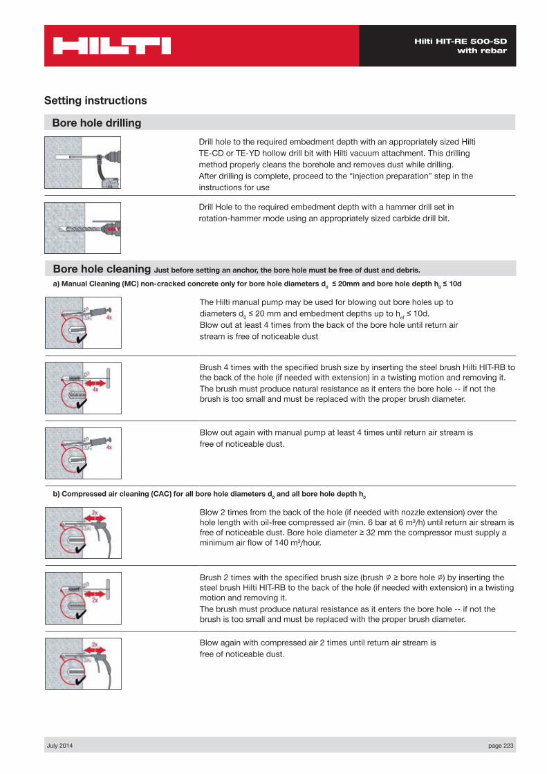
July 2014 page 223
Hilti HIT-RE 500-SD with rebar
Setting instructions
Bore hole drillingDrill hole to the required embedment depth with an appropriately sized HiltiTE-CD or TE-YD hollow drill bit with Hilti vacuum attachment. This drillingmethod properly cleans the borehole and removes dust while drilling.After drilling is complete, proceed to the “injection preparation” step in theinstructions for use
Drill Hole to the required embedment depth with a hammer drill set inrotation-hammer mode using an appropriately sized carbide drill bit.
b) Compressed air cleaning (CAC) for all bore hole diameters d0 and all bore hole depth h0
Blow 2 times from the back of the hole (if needed with nozzle extension) over the hole length with oil-free compressed air (min. 6 bar at 6 m³/h) until return air stream is free of noticeable dust. Bore hole diameter ≥ 32 mm the compressor must supply a minimum air flow of 140 m³/hour.
Brush 2 times with the specified brush size (brush ∅ ≥ bore hole ∅) by inserting the steel brush Hilti HIT-RB to the back of the hole (if needed with extension) in a twisting motion and removing it.The brush must produce natural resistance as it enters the bore hole -- if not the brush is too small and must be replaced with the proper brush diameter.
Blow again with compressed air 2 times until return air stream isfree of noticeable dust.
Bore hole cleaning Just before setting an anchor, the bore hole must be free of dust and debris.
a) Manual Cleaning (MC) non-cracked concrete only for bore hole diameters d0 ≤ 20mm and bore hole depth h0 ≤ 10d
The Hilti manual pump may be used for blowing out bore holes up todiameters d0 ≤ 20 mm and embedment depths up to hef ≤ 10d.Blow out at least 4 times from the back of the bore hole until return airstream is free of noticeable dust
Brush 4 times with the specified brush size by inserting the steel brush Hilti HIT-RB to the back of the hole (if needed with extension) in a twisting motion and removing it.The brush must produce natural resistance as it enters the bore hole -- if not the brush is too small and must be replaced with the proper brush diameter.
Blow out again with manual pump at least 4 times until return air stream isfree of noticeable dust.
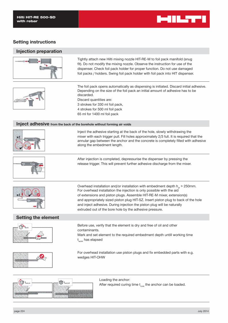
page 224 July 2014
Hilti HIT-RE 500-SD with rebar
Setting instructions
Inject adhesive from the back of the borehole without forming air voids
Inject the adhesive starting at the back of the hole, slowly withdrawing themixer with each trigger pull. Fill holes approximately 2/3 full. It is required that the annular gap between the anchor and the concrete is completely filled with adhesive along the embedment length.
After injection is completed, depressurise the dispenser by pressing therelease trigger. This will prevent further adhesive discharge from the mixer.
Overhead installation and/or installation with embedment depth hef > 250mm. For overhead installation the injection is only possible with the aidof extensions and piston plugs. Assemble HIT-RE-M mixer, extension(s)and appropriately sized piston plug HIT-SZ. Insert piston plug to back of the holeand inject adhesive. During injection the piston plug will be naturallyextruded out of the bore hole by the adhesive pressure.
Setting the elementBefore use, verify that the element is dry and free of oil and othercontaminants.Mark and set element to the required embedment depth untill working timetwork has elapsed
For overhead installation use piston plugs and fix embedded parts with e.g.wedges HIT-OHW
Loading the anchor:After required curing time tcure the anchor can be loaded.
Injection preparationTightly attach new Hilti mixing nozzle HIT-RE-M to foil pack manifold (snugfit). Do not modify the mixing nozzle. Observe the instruction for use of thedispenser. Check foil pack holder for proper function. Do not use damagedfoil packs / holders. Swing foil pack holder with foil pack into HIT dispenser.
The foil pack opens automatically as dispensing is initiated. Discard initial adhesive. Depending on the size of the foil pack an initial amount of adhesive has to be discarded.Discard quantities are:3 strokes for 330 ml foil pack,4 strokes for 500 ml foil pack65 ml for 1400 ml foil pack
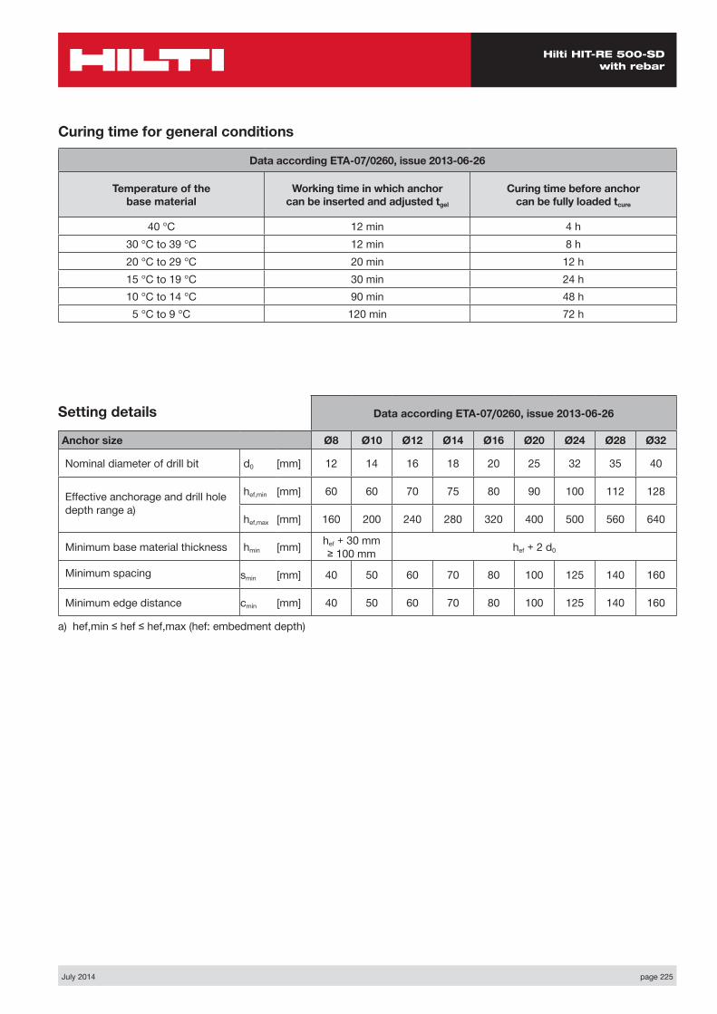
July 2014 page 225
Hilti HIT-RE 500-SD with rebar
Curing time for general conditions
Data according ETA-07/0260, issue 2013-06-26
Temperature of the base material
Working time in which anchor can be inserted and adjusted tgel
Curing time before anchor can be fully loaded tcure
40 °C 12 min 4 h30 °C to 39 °C 12 min 8 h20 °C to 29 °C 20 min 12 h15 °C to 19 °C 30 min 24 h10 °C to 14 °C 90 min 48 h5 °C to 9 °C 120 min 72 h
Data according ETA-07/0260, issue 2013-06-26
Anchor size Ø8 Ø10 Ø12 Ø14 Ø16 Ø20 Ø24 Ø28 Ø32
Nominal diameter of drill bit d0 [mm] 12 14 16 18 20 25 32 35 40
Effective anchorage and drill hole depth range a)
hef,min [mm] 60 60 70 75 80 90 100 112 128
hef,max [mm] 160 200 240 280 320 400 500 560 640
Minimum base material thickness hmin [mm] hef + 30 mm ≥ 100 mm hef + 2 d0
Minimum spacing smin [mm] 40 50 60 70 80 100 125 140 160
Minimum edge distance cmin [mm] 40 50 60 70 80 100 125 140 160
a) hef,min ≤ hef ≤ hef,max (hef: embedment depth)
Setting details
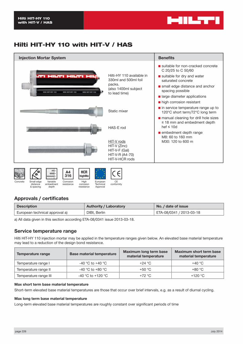
page 226 July 2014
Hilti HIT-HY 110 with HIT-V / HAS
Static mixer
HAS-E rod
CE conformity
Small edge distance
& spacing
European Technical Approval
Concrete
A4 316
Corrosion resistance
HCR highMo
High corrosion resistance
Hilti HIT-HY 110 with HIT-V / HAS
Injection Mortar System
Variable embedment
depth
Hilti-HY 110 available in 330ml and 500ml foil packs.(also 1400ml subject to lead time)
Approvals / certificatesDescription Authority / Laboratory No. / date of issueEuropean technical approval a) DIBt, Berlin ETA-08/0341 / 2013-03-18
a) All data given in this section according ETA-08/0341 issue 2013-03-18.
Service temperature rangeHilti HIT-HY 110 injection mortar may be applied in the temperature ranges given below. An elevated base material temperature may lead to a reduction of the design bond resistance.
Temperature range Base material temperature Maximum long term base material temperature
Maximum short term base material temperature
Temperature range I -40 °C to +40 °C +24 °C +40 °CTemperature range II -40 °C to +80 °C +50 °C +80 °CTemperature range III -40 °C to +120 °C +72 °C +120 °C
Max short term base material temperatureShort-term elevated base material temperatures are those that occur over brief intervals, e.g. as a result of diurnal cycling.
Max long term base material temperatureLong-term elevated base material temperatures are roughly constant over significant periods of time
Benefits
■ suitable for non-cracked concrete C 20/25 to C 50/60
■ suitable for dry and water saturated concrete
■ small edge distance and anchor spacing possible
■ large diameter applications■ high corrosion resistant■ in service temperature range up to
120°C short term/72°C long term■ manual cleaning for drill hole sizes
≤ 18 mm and embedment depth hef ≤ 10d
■ embedment depth range M8: 60 to 160 mm M30: 120 to 600 mHIT-V rods
HIT-V (Zinc)HIT-V-F (Gal)HIT-V-R (A4-70)HIT-V-HCR rods
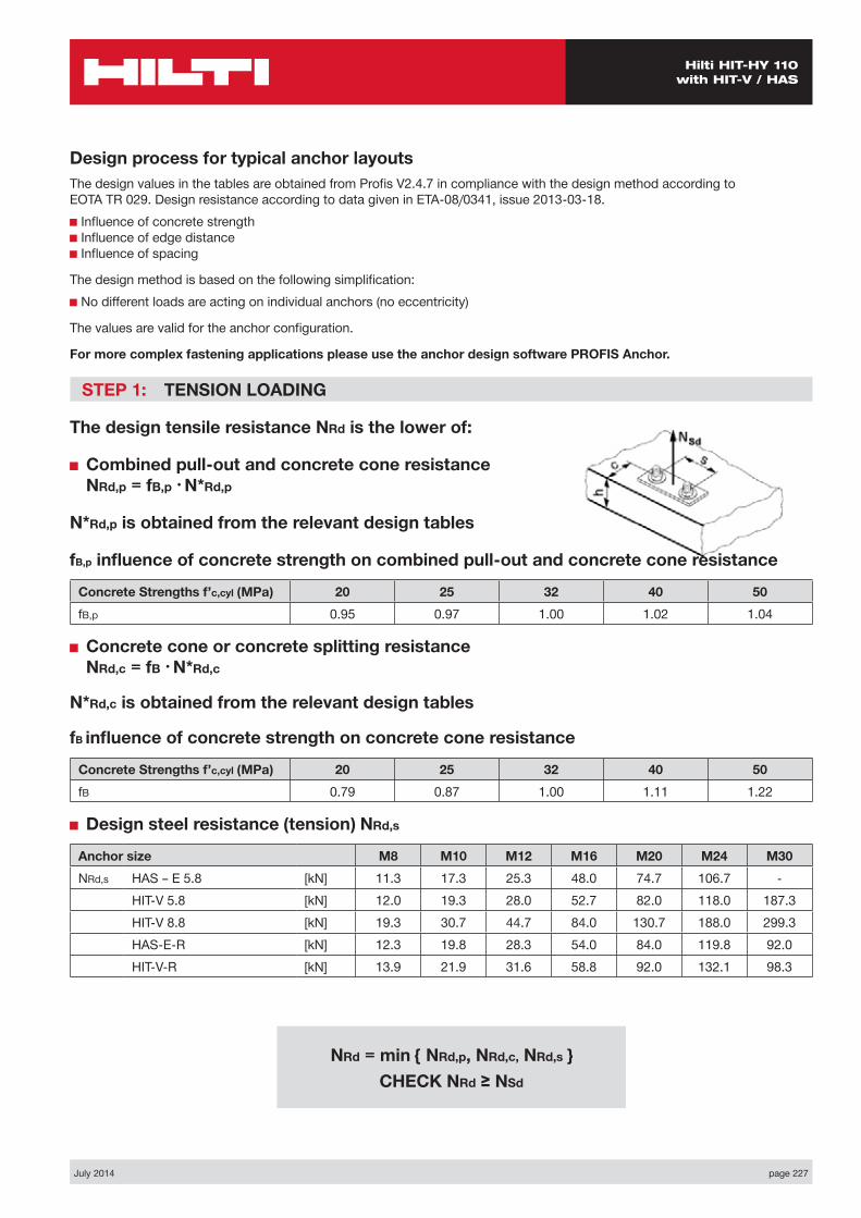
July 2014 page 227
Hilti HIT-HY 110 with HIT-V / HAS
Design process for typical anchor layoutsThe design values in the tables are obtained from Profis V2.4.7 in compliance with the design method according to EOTA TR 029. Design resistance according to data given in ETA-08/0341, issue 2013-03-18.■ Influence of concrete strength ■ Influence of edge distance ■ Influence of spacing
The design method is based on the following simplification:■ No different loads are acting on individual anchors (no eccentricity)
The values are valid for the anchor configuration.
For more complex fastening applications please use the anchor design software PROFIS Anchor.
STEP 1: TENSION LOADING
The design tensile resistance NRd is the lower of:
■ Combined pull-out and concrete cone resistance NRd,p = fB,p • N*Rd,p
N*Rd,p is obtained from the relevant design tables
fB,p influence of concrete strength on combined pull-out and concrete cone resistance
Concrete Strengths f’c,cyl (MPa) 20 25 32 40 50fB,p 0.95 0.97 1.00 1.02 1.04
■ Concrete cone or concrete splitting resistance NRd,c = fB • N*Rd,c
N*Rd,c is obtained from the relevant design tables
fB influence of concrete strength on concrete cone resistance
Concrete Strengths f’c,cyl (MPa) 20 25 32 40 50fB 0.79 0.87 1.00 1.11 1.22
■ Design steel resistance (tension) NRd,s
Anchor size M8 M10 M12 M16 M20 M24 M30NRd,s HAS – E 5.8 [kN] 11.3 17.3 25.3 48.0 74.7 106.7 -
HIT-V 5.8 [kN] 12.0 19.3 28.0 52.7 82.0 118.0 187.3HIT-V 8.8 [kN] 19.3 30.7 44.7 84.0 130.7 188.0 299.3HAS-E-R [kN] 12.3 19.8 28.3 54.0 84.0 119.8 92.0HIT-V-R [kN] 13.9 21.9 31.6 58.8 92.0 132.1 98.3
NRd = min { NRd,p, NRd,c, NRd,s } CHECK NRd ≥ NSd
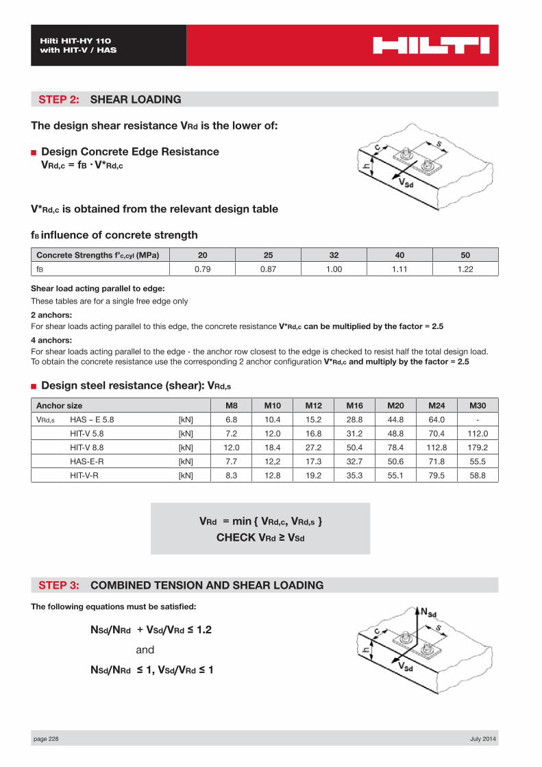
page 228 July 2014
Hilti HIT-HY 110 with HIT-V / HAS
STEP 2: SHEAR LOADING
The design shear resistance VRd is the lower of:
■ Design Concrete Edge Resistance VRd,c = fB • V*Rd,c
V*Rd,c is obtained from the relevant design table
fB influence of concrete strength
Concrete Strengths f’c,cyl (MPa) 20 25 32 40 50fB 0.79 0.87 1.00 1.11 1.22
Shear load acting parallel to edge:These tables are for a single free edge only2 anchors:For shear loads acting parallel to this edge, the concrete resistance V*Rd,c can be multiplied by the factor = 2.54 anchors:For shear loads acting parallel to the edge - the anchor row closest to the edge is checked to resist half the total design load. To obtain the concrete resistance use the corresponding 2 anchor configuration V*Rd,c and multiply by the factor = 2.5
■ Design steel resistance (shear): VRd,s
Anchor size M8 M10 M12 M16 M20 M24 M30VRd,s HAS – E 5.8 [kN] 6.8 10.4 15.2 28.8 44.8 64.0 -
HIT-V 5.8 [kN] 7.2 12.0 16.8 31.2 48.8 70.4 112.0HIT-V 8.8 [kN] 12.0 18.4 27.2 50.4 78.4 112.8 179.2HAS-E-R [kN] 7.7 12,2 17.3 32.7 50.6 71.8 55.5HIT-V-R [kN] 8.3 12.8 19.2 35.3 55.1 79.5 58.8
STEP 3: COMBINED TENSION AND SHEAR LOADING
The following equations must be satisfied:
NSd/NRd + VSd/VRd ≤ 1.2
and
NSd/NRd ≤ 1, VSd/VRd ≤ 1
VRd = min { VRd,c, VRd,s } CHECK VRd ≥ VSd
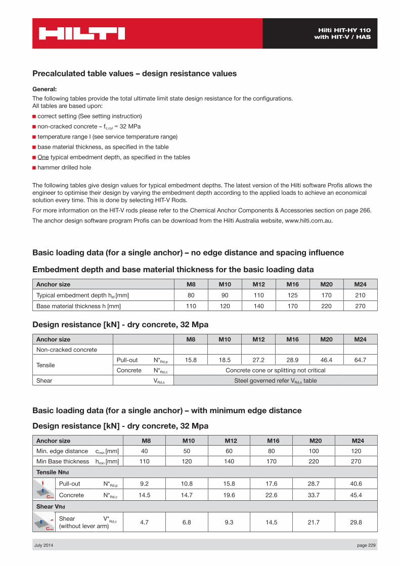
July 2014 page 229
Hilti HIT-HY 110 with HIT-V / HAS
Basic loading data (for a single anchor) – no edge distance and spacing influence
Embedment depth and base material thickness for the basic loading data
Anchor size M8 M10 M12 M16 M20 M24
Typical embedment depth hef [mm] 80 90 110 125 170 210
Base material thickness h [mm] 110 120 140 170 220 270
Precalculated table values – design resistance values
General:The following tables provide the total ultimate limit state design resistance for the configurations. All tables are based upon:■ correct setting (See setting instruction)■ non-cracked concrete – fc,cyl = 32 MPa■ temperature range I (see service temperature range)■ base material thickness, as specified in the table■ One typical embedment depth, as specified in the tables■ hammer drilled hole
The following tables give design values for typical embedment depths. The latest version of the Hilti software Profis allows the engineer to optimise their design by varying the embedment depth according to the applied loads to achieve an economical solution every time. This is done by selecting HIT-V Rods.For more information on the HIT-V rods please refer to the Chemical Anchor Components & Accessories section on page 266.The anchor design software program Profis can be download from the Hilti Australia website, www.hilti.com.au.
Design resistance [kN] - dry concrete, 32 Mpa
Anchor size M8 M10 M12 M16 M20 M24Non-cracked concrete
Tensile Pull-out N*Rd,p 15.8 18.5 27.2 28.9 46.4 64.7Concrete N*Rd,c Concrete cone or splitting not critical
Shear VRd,s Steel governed refer VRd,s table
Basic loading data (for a single anchor) – with minimum edge distance
Design resistance [kN] - dry concrete, 32 Mpa
Anchor size M8 M10 M12 M16 M20 M24Min. edge distance cmin [mm] 40 50 60 80 100 120Min Base thickness hmin [mm] 110 120 140 170 220 270
Tensile NRd
Pull-out N*Rd,p 9.2 10.8 15.8 17.6 28.7 40.6
Concrete N*Rd,c 14.5 14.7 19.6 22.6 33.7 45.4
Shear VRd
Shear V*Rd,c (without lever arm) 4.7 6.8 9.3 14.5 21.7 29.8

page 230 July 2014
Hilti HIT-HY 110 with HIT-V / HAS
Nsd
Vsd
S1
C
h
Two Anchors Table 1: One edge influence
Design Data: fc,cyl=32 MPa
Anchor size M8 M10 M12 M16 M20 M24Typical embedment depth hef [mm] 80 90 110 125 170 210
Base material thickness h [mm] 110 120 140 170 220 270
ANCHOR
M8Edge C (mm)
40 80 100 150 170spacings1 (mm)
tension shear tension shear tension shear tension shear tension shearN*Rd,p N*Rd,c V*Rrd,c N*Rd,p N*Rd,c V*Rrd,c N*Rd,p N*Rd,c V*Rrd,c N*Rd,p N*Rd,c V*Rrd,c N*Rd,p N*Rd,c V*Rrd,c
40 12.7 16.2 6.3 18.8 21.1 13.1 21.8 23.7 15.4 21.8 30.9 21.0 21.8 34.1 23.2
80 14.2 17.9 7.9 21.1 23.3 15.0 24.4 26.2 17.2 24.4 34.2 22.7 24.4 37.6 24.9
100 15.0 18.8 8.6 22.3 24.4 15.9 25.7 27.4 18.1 25.7 35.8 23.6 25.7 39.4 25.7
120 15.7 19.6 9.4 23.4 25.5 16.9 27.0 28.7 19.0 27.0 37.4 24.4 27.0 41.2 26.6
150 16.8 20.4 9.4 25.0 27.2 18.3 28.9 30.6 20.4 28.9 39.9 25.7 28.9 43.9 27.9
200 18.4 23.0 9.4 27.4 29.9 20.6 31.6 33.7 22.6 31.6 43.9 27.9 31.6 48.4 30.0
ANCHOR
M10Edge C (mm)
50 80 100 150 200spacings1 (mm)
tension shear tension shear tension shear tension shear tension shearN*Rd,p N*Rd,c V*Rrd,c N*Rd,p N*Rd,c V*Rrd,c N*Rd,p N*Rd,c V*Rrd,c N*Rd,p N*Rd,c V*Rrd,c N*Rd,p N*Rd,c V*Rrd,c
50 14.5 16.6 9.0 18.6 19.7 15.0 21.6 21.9 17.4 25.0 27.8 23.4 25.0 34.1 29.3
100 16.4 18.4 11.3 21.0 21.9 17.6 24.4 24.3 19.9 28.2 30.9 25.7 28.2 38.0 31.5
150 18.3 20.3 13.5 23.4 24.1 20.2 27.2 26.8 22.4 31.4 34.0 28.1 31.4 41.8 33.8
200 20.1 22.2 13.5 25.7 26.3 22.8 29.9 29.2 24.9 34.5 37.2 30.4 34.5 45.6 36.0
250 21.6 24.0 13.5 27.7 28.5 24.8 32.1 31.7 27.4 37.1 40.3 32.7 37.1 49.4 38.3
300 21.6 25.9 13.5 27.7 30.7 24.8 32.1 34.1 29.9 37.1 43.4 35.1 37.1 53.3 40.6
ANCHOR
M12Edge C (mm)
60 80 100 150 200spacings1 (mm)
tension shear tension shear tension shear tension shear tension shearN*Rd,p N*Rd,c V*Rrd,c N*Rd,p N*Rd,c V*Rrd,c N*Rd,p N*Rd,c V*Rrd,c N*Rd,p N*Rd,c V*Rrd,c N*Rd,p N*Rd,c V*Rrd,c
60 21.0 22.0 12.3 24.2 24.1 16.7 27.7 26.4 20.7 36.2 32.4 27.3 36.2 39.0 33.8
100 22.9 23.5 14.4 26.4 25.9 18.9 30.1 28.3 23.0 39.4 34.7 29.4 39.4 41.8 35.8
150 25.2 25.5 16.9 29.1 28.0 21.7 33.2 30.6 25.9 43.3 37.6 32.1 43.4 45.2 38.4
200 27.5 27.5 18.5 31.8 30.2 24.5 36.2 33.0 28.7 47.4 40.5 34.8 47.4 48.7 41.0
250 29.8 29.5 18.5 34.3 32.4 26.7 39.2 35.4 31.6 51.3 43.4 37.1 51.3 52.2 43.5
300 31.7 31.5 18.5 36.5 34.5 26.7 41.6 37.8 34.5 54.4 46.4 40.1 54.4 55.7 46.1

July 2014 page 231
Hilti HIT-HY 110 with HIT-V / HAS
ANCHOR
M24Edge C (mm)
120 150 200 250 350spacings1 (mm)
tension shear tension shear tension shear tension shear tension shearN*Rd,p N*Rd,c V*Rrd,c N*Rd,p N*Rd,c V*Rrd,c N*Rd,p N*Rd,c V*Rrd,c N*Rd,p N*Rd,c V*Rrd,c N*Rd,p N*Rd,c V*Rrd,c
120 54.8 51.2 39.7 61.8 55.1 49.7 74.3 61.9 64.0 87.3 69.0 73.6 87.3 84.3 92.6
150 56.9 52.6 42.3 64.2 56.6 52.3 77.3 63.6 66.7 90.8 70.9 76.1 90.8 86.6 95.0
200 60.5 55.0 46.4 68.2 59.2 56.6 82.1 66.5 71.1 96.5 74.1 80.4 96.5 90.6 98.9
250 64.1 57.4 50.5 72.3 61.8 61.0 87.0 69.4 75.6 102.2 77.4 84.6 102.1 94.5 102.9
300 67.6 59.8 54.7 76.3 64.4 65.3 91.8 72.3 80.0 107.8 80.6 88.8 107.8 98.5 106.9
350 71.1 62.2 58.8 80.2 66.9 69.7 96.5 75.2 84.5 113.4 83.8 93.1 113.4 102.4 110.8
ANCHOR
M16Edge C (mm)
80 100 150 200 250spacings1 (mm)
tension shear tension shear tension shear tension shear tension shearN*Rd,p N*Rd,c V*Rrd,c N*Rd,p N*Rd,c V*Rrd,c N*Rd,p N*Rd,c V*Rrd,c N*Rd,p N*Rd,c V*Rrd,c N*Rd,p N*Rd,c V*Rrd,c
80 23.6 25.9 19.3 26.6 28.2 24.4 34.4 34.2 33.3 38.8 38.9 40.1 38.8 45.5 47.2
100 24.5 26.7 20.5 27.5 29.1 25.7 35.7 35.3 34.6 40.2 42.1 41.8 40.2 49.3 49.0
150 26.7 27.8 23.6 30.0 30.1 28.9 38.9 38.1 37.8 43.8 43.2 44.2 43.8 50.5 51.2
200 28.9 29.7 26.6 32.4 32.2 32.1 42.0 39.0 40.3 47.4 48.6 47.9 47.3 57.1 54.8
250 31.0 33.1 29.1 34.8 35.9 35.3 45.2 43.6 44.1 50.9 49.3 50.1 50.9 57.7 56.9
300 33.1 33.7 29.1 37.2 36.5 38.6 48.2 44.1 46.5 54.3 52.4 53.0 54.3 61.3 59.7
ANCHOR
M20Edge C (mm)
120 150 200 250 300spacings1 (mm)
tension shear tension shear tension shear tension shear tension shearN*Rd,p N*Rd,c V*Rrd,c N*Rd,p N*Rd,c V*Rrd,c N*Rd,p N*Rd,c V*Rrd,c N*Rd,p N*Rd,c V*Rrd,c N*Rd,p N*Rd,c V*Rrd,c
100 38.6 38.0 28.9 48.5 44.1 43.6 59.5 50.5 52.1 62.5 57.3 60.6 62.5 64.6 69.0
150 41.5 40.2 32.5 52.2 46.6 47.5 64.0 53.4 55.8 67.2 60.6 64.2 67.2 68.3 72.5
200 44.4 42.4 36.1 55.9 49.2 51.5 68.5 56.3 59.6 72.0 63.9 67.7 72.0 72.0 75.9
250 47.4 44.6 39.7 59.5 51.7 55.4 73.0 59.2 63.3 76.7 67.3 71.3 76.7 75.7 79.3
300 50.2 46.8 43.4 63.1 54.2 59.4 77.4 62.2 67.0 81.3 70.6 74.9 81.3 79.4 82.8
350 53.1 49.0 43.4 66.7 56.8 63.4 81.8 65.1 70.7 85.9 73.9 78.4 85.9 83.1 86.3

page 232 July 2014
Hilti HIT-HY 110 with HIT-V / HAS
Four anchors Table 2: One edge influence
Design Data: fc,cyl=32 MPa
Anchor size M8 M10 M12 M16 M20 M24Typical embedment depth hef [mm] 80 90 110 125 170 210
Base material thickness h [mm] 110 120 140 170 220 270
ANCHOR
M8Edge C (mm)
40 80 100 150 200spacing
s1=s2 (mm)
tension shear tension shear tension shear tension shear tension shearN*Rd,p N*Rd,c V*Rrd,c N*Rd,p N*Rd,c V*Rrd,c N*Rd,p N*Rd,c V*Rrd,c N*Rd,p N*Rd,c V*Rrd,c N*Rd,p N*Rd,c V*Rrd,c
40 19.2 19.3 12.6 27.1 24.4 17.7 30.9 27.2 19.9 30.9 34.8 25.4 30.9 38.1 30.9
80 25.2 24.7 15.8 34.3 30.7 23.8 38.6 34.0 26.0 38.6 42.7 31.4 38.6 46.5 36.8
100 28.4 27.7 17.3 38.2 34.1 26.8 42.7 37.6 29.0 42.7 47.0 34.4 42.7 51.0 39.8
120 31.7 30.8 18.8 42.1 37.7 29.8 47.0 41.4 32.0 47.0 51.5 37.4 47.0 55.8 42.7
150 36.5 35.8 18.8 48.2 43.5 34.3 53.5 47.5 36.4 53.5 58.6 41.8 53.5 63.3 47.0
200 44.5 45.0 18.8 57.4 53.9 41.2 63.3 58.6 43.7 63.3 71.4 49.0 63.3 76.9 54.2
ANCHOR
M10Edge C (mm)
50 80 100 150 200spacing
s1=s2 (mm)
tension shear tension shear tension shear tension shear tension shearN*Rd,p N*Rd,c V*Rrd,c N*Rd,p N*Rd,c V*Rrd,c N*Rd,p N*Rd,c V*Rrd,c N*Rd,p N*Rd,c V*Rrd,c N*Rd,p N*Rd,c V*Rrd,c
50 21.6 19.9 17.5 26.7 23.2 21.0 30.4 25.5 23.4 34.6 31.8 29.3 34.6 38.4 35.1
100 28.6 25.9 22.5 34.7 29.8 29.2 39.0 32.5 31.6 43.9 39.8 37.3 43.9 47.5 43.0
150 36.4 32.6 27.0 43.4 37.1 37.2 48.4 40.2 39.5 54.0 48.7 45.1 54.0 57.6 50.8
200 44.8 40.0 27.0 52.7 45.2 45.0 58.4 48.8 47.3 64.7 58.5 52.9 64.7 68.6 58.4
250 52.1 48.2 27.0 61.0 54.1 49.7 67.2 58.2 55.0 74.2 69.2 60.5 74.2 80.6 66.0
300 52.1 57.2 27.0 61.0 63.8 49.7 67.2 68.5 59.8 74.1 80.8 68.1 74.2 93.6 73.6
ANCHOR
M12Edge C (mm)
60 80 100 150 200spacing
s1=s2 (mm)
tension shear tension shear tension shear tension shear tension shearN*Rd,p N*Rd,c V*Rrd,c N*Rd,p N*Rd,c V*Rrd,c N*Rd,p N*Rd,c V*Rrd,c N*Rd,p N*Rd,c V*Rrd,c N*Rd,p N*Rd,c V*Rrd,c
60 30.8 26.3 23.3 34.8 28.6 26.0 39.0 30.9 28.6 49.4 37.3 35.1 49.4 44.2 41.5
100 37.6 31.2 28.8 42.0 33.7 33.3 46.7 36.4 35.8 58.4 43.4 42.2 58.4 51.1 48.5
150 46.8 38.0 33.8 52.0 40.9 42.2 57.3 43.8 44.7 70.5 51.8 50.9 70.5 60.4 57.1
200 56.8 45.4 37.0 62.6 48.6 49.0 68.7 52.0 53.3 83.5 60.9 59.5 83.5 70.5 65.6
250 67.4 53.3 37.0 73.9 57.0 53.4 80.7 60.8 61.9 97.2 70.7 68.0 97.2 81.4 74.0
300 76.4 62.1 37.0 83.5 66.1 53.4 90.9 70.3 69.0 108.8 81.3 76.3 108.8 93.0 82.4
Nsd
Vsd
S2
S1
C
h

July 2014 page 233
Hilti HIT-HY 110 with HIT-V / HAS
ANCHOR
M24Edge C (mm)
120 150 200 250 350spacing
s1=s2 (mm)
tension shear tension shear tension shear tension shear tension shearN*Rd,p N*Rd,c V*Rrd,c N*Rd,p N*Rd,c V*Rrd,c N*Rd,p N*Rd,c V*Rrd,c N*Rd,p N*Rd,c V*Rrd,c N*Rd,p N*Rd,c V*Rrd,c
120 80.8 61.5 71.7 89.5 65.7 77.4 104.9 72.9 86.9 120.7 80.4 96.4 120.7 96.5 115.0
150 88.2 65.9 79.9 97.3 70.2 85.6 113.5 77.7 95.0 130.1 85.6 104.3 130.1 102.4 122.8
200 101.1 73.5 92.8 111.0 78.2 98.9 128.6 86.2 108.2 146.6 94.6 117.3 146.6 112.6 142.9
250 114.8 81.5 101.0 125.5 86.5 112.0 144.5 95.1 121.1 163.9 104.0 130.2 163.9 123.2 148.3
300 129.1 90.0 109.4 140.7 95.3 124.9 161.1 104.4 133.9 182.0 114.0 142.9 182.0 134.3 160.8
350 144.0 98.8 117.6 156.5 104.4 137.6 178.4 114.2 146.6 200.7 124.3 155.5 200.7 145.9 173.3
ANCHOR
M16Edge C (mm)
80 100 150 200 250spacing
s1=s2 (mm)
tension shear tension shear tension shear tension shear tension shearN*Rd,p N*Rd,c V*Rrd,c N*Rd,p N*Rd,c V*Rrd,c N*Rd,p N*Rd,c V*Rrd,c N*Rd,p N*Rd,c V*Rrd,c N*Rd,p N*Rd,c V*Rrd,c
80 34.8 31.9 34.8 38.4 34.3 37.8 48.2 40.7 45.0 53.5 47.7 52.2 53.5 55.2 59.3
100 37.9 34.4 39.0 41.7 37.0 41.9 51.9 43.7 49.1 57.4 51.0 56.2 57.4 58.9 63.2
150 45.9 41.3 47.2 50.2 44.1 52.0 61.6 51.7 59.0 67.8 59.9 66.0 67.8 68.6 72.9
200 54.6 48.7 53.2 59.3 51.9 61.8 72.0 60.3 68.7 78.9 69.4 75.6 78.9 79.1 82.5
250 63.7 56.7 58.2 69.0 60.3 70.6 83.0 69.6 78.4 90.5 79.6 85.2 90.5 90.3 92.0
300 73.4 65.4 58.2 79.2 69.3 77.2 94.5 79.6 87.8 102.8 90.6 94.6 102.8 102.3 101.4
ANCHOR
M20Edge C (mm)
100 150 200 250 300spacing
s1=s2 (mm)
tension shear tension shear tension shear tension shear tension shearN*Rd,p N*Rd,c V*Rrd,c N*Rd,p N*Rd,c V*Rrd,c N*Rd,p N*Rd,c V*Rrd,c N*Rd,p N*Rd,c V*Rrd,c N*Rd,p N*Rd,c V*Rrd,c
100 56.9 45.9 52.1 69.2 52.3 60.6 82.6 59.2 69.0 86.2 66.4 77.3 86.2 74.0 85.6
150 67.2 52.7 64.2 80.7 59.7 72.4 95.5 67.1 80.7 99.5 75.0 88.7 99.5 83.3 97.0
200 78.3 60.0 72.2 93.1 67.6 84.0 109.2 75.6 92.2 113.6 84.1 100.3 113.6 93.0 108.3
250 90.0 67.7 79.5 106.1 75.9 95.5 123.7 84.6 103.5 128.5 93.8 111.5 128.5 103.4 119.5
300 102.2 75.8 86.8 119.8 84.7 106.7 138.9 94.1 114.7 144.0 103.9 122.6 144.0 114.3 130.5
350 115.0 84.4 86.8 134.0 94.0 117.9 154.6 104.0 125.7 160.1 114.6 133.6 160.1 125.7 141.5
Shear design: The concrete edge resistance value in this table uses all 4 anchors in shear. You will need to ensure the gap between anchor and the plate is filled. This can be achieved using the Hilti Dynamic Set. (Refer page 41 for further details)
The concrete edge resistance values have been obtained by taking the lesser of:1. First row resistance multiplied by number of rows and 2. The concrete edge resistance of the furthest row.
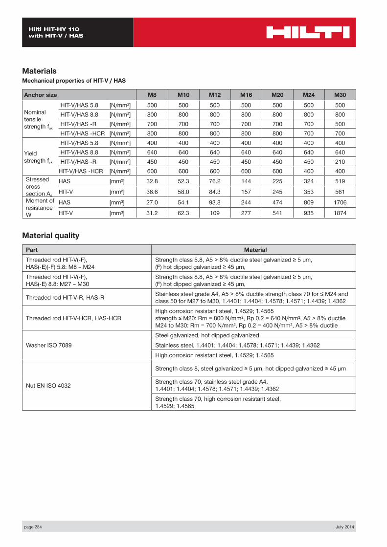
page 234 July 2014
Hilti HIT-HY 110 with HIT-V / HAS
MaterialsMechanical properties of HIT-V / HAS
Anchor size M8 M10 M12 M16 M20 M24 M30
Nominal tensile strength fuk
HIT-V/HAS 5.8 [N/mm²] 500 500 500 500 500 500 500HIT-V/HAS 8.8 [N/mm²] 800 800 800 800 800 800 800HIT-V/HAS -R [N/mm²] 700 700 700 700 700 700 500HIT-V/HAS -HCR [N/mm²] 800 800 800 800 800 700 700
Yield strength fyk
HIT-V/HAS 5.8 [N/mm²] 400 400 400 400 400 400 400HIT-V/HAS 8.8 [N/mm²] 640 640 640 640 640 640 640HIT-V/HAS -R [N/mm²] 450 450 450 450 450 450 210
HIT-V/HAS -HCR [N/mm²] 600 600 600 600 600 400 400Stressed cross- section As
HAS [mm²] 32.8 52.3 76.2 144 225 324 519
HIT-V [mm²] 36.6 58.0 84.3 157 245 353 561Moment of resistance W
HAS [mm³] 27.0 54.1 93.8 244 474 809 1706
HIT-V [mm³] 31.2 62.3 109 277 541 935 1874
Material quality
Part MaterialThreaded rod HIT-V(-F), HAS(-E)(-F) 5.8: M8 – M24
Strength class 5.8, A5 > 8% ductile steel galvanized ≥ 5 μm, (F) hot dipped galvanized ≥ 45 μm,
Threaded rod HIT-V(-F), HAS(-E) 8.8: M27 – M30
Strength class 8.8, A5 > 8% ductile steel galvanized ≥ 5 μm, (F) hot dipped galvanized ≥ 45 μm,
Threaded rod HIT-V-R, HAS-R Stainless steel grade A4, A5 > 8% ductile strength class 70 for ≤ M24 and class 50 for M27 to M30, 1.4401; 1.4404; 1.4578; 1.4571; 1.4439; 1.4362
Threaded rod HIT-V-HCR, HAS-HCRHigh corrosion resistant steel, 1.4529; 1.4565 strength ≤ M20: Rm = 800 N/mm², Rp 0.2 = 640 N/mm², A5 > 8% ductile M24 to M30: Rm = 700 N/mm², Rp 0.2 = 400 N/mm², A5 > 8% ductile
Washer ISO 7089Steel galvanized, hot dipped galvanizedStainless steel, 1.4401; 1.4404; 1.4578; 1.4571; 1.4439; 1.4362High corrosion resistant steel, 1.4529; 1.4565
Nut EN ISO 4032
Strength class 8, steel galvanized ≥ 5 μm, hot dipped galvanized ≥ 45 μm
Strength class 70, stainless steel grade A4, 1.4401; 1.4404; 1.4578; 1.4571; 1.4439; 1.4362Strength class 70, high corrosion resistant steel, 1.4529; 1.4565
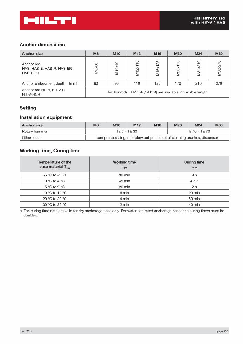
July 2014 page 235
Hilti HIT-HY 110 with HIT-V / HAS
Anchor dimensions
Anchor size M8 M10 M12 M16 M20 M24 M30
Anchor rod HAS, HAS-E, HAS-R, HAS-ER HAS-HCR M
8x80
M10
x90
M12
x110
M16
x125
M20
x170
M24
x210
M30
x270
Anchor embedment depth [mm] 80 90 110 125 170 210 270
Anchor rod HIT-V, HIT-V-R, HIT-V-HCR Anchor rods HIT-V (-R / -HCR) are available in variable length
Setting
Installation equipmentAnchor size M8 M10 M12 M16 M20 M24 M30Rotary hammer TE 2 – TE 30 TE 40 – TE 70Other tools compressed air gun or blow out pump, set of cleaning brushes, dispenser
Working time, Curing time
Temperature of the base material TBM
Working time tgel
Curing time tcure
-5 °C to -1 °C 90 min 9 h0 °C to 4 °C 45 min 4.5 h5 °C to 9 °C 20 min 2 h
10 °C to 19 °C 6 min 90 min20 °C to 29 °C 4 min 50 min30 °C to 39 °C 2 min 40 min
a) The curing time data are valid for dry anchorage base only. For water saturated anchorage bases the curing times must be doubled.
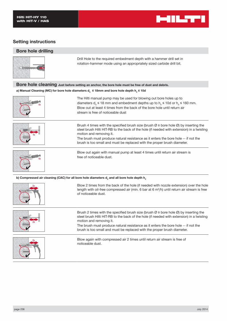
page 236 July 2014
Hilti HIT-HY 110 with HIT-V / HAS
Setting instructions
Bore hole drillingDrill Hole to the required embedment depth with a hammer drill set inrotation-hammer mode using an appropriately sized carbide drill bit.
Bore hole cleaning Just before setting an anchor, the bore hole must be free of dust and debris.
a) Manual Cleaning (MC) for bore hole diameters d0 ≤ 18mm and bore hole depth h0 ≤ 10d
The Hilti manual pump may be used for blowing out bore holes up todiameters d0 ≤ 18 mm and embedment depths up to h0 ≤ 10d or h0 ≤ 160 mm.Blow out at least 4 times from the back of the bore hole until return airstream is free of noticeable dust
Brush 4 times with the specified brush size (brush Ø ≥ bore hole Ø) by inserting the steel brush Hilti HIT-RB to the back of the hole (if needed with extension) in a twisting motion and removing it.The brush must produce natural resistance as it enters the bore hole -- if not the brush is too small and must be replaced with the proper brush diameter.
Blow out again with manual pump at least 4 times until return air stream isfree of noticeable dust.
b) Compressed air cleaning (CAC) for all bore hole diameters d0 and all bore hole depth h0
Blow 2 times from the back of the hole (if needed with nozzle extension) over the hole length with oil-free compressed air (min. 6 bar at 6 m³/h) until return air stream is free of noticeable dust.
Brush 2 times with the specified brush size (brush Ø ≥ bore hole Ø) by inserting the steel brush Hilti HIT-RB to the back of the hole (if needed with extension) in a twisting motion and removing it.The brush must produce natural resistance as it enters the bore hole -- if not the brush is too small and must be replaced with the proper brush diameter.
Blow again with compressed air 2 times until return air stream is free of noticeable dust.

July 2014 page 237
Hilti HIT-HY 110 with HIT-V / HAS
Setting instructions
Injection preparationTightly attach new Hilti mixing nozzle HIT-M1 to foil pack manifold (snugfit). Do not modify the mixing nozzle. Observe the instruction for use of thedispenser and the mortar. Check foil pack holder for proper function. Do not use damaged foil packs / holders. Insert foil pack into foil pack holder and put holder into HIT dispenser.
The foil pack opens automatically as dispensing is initiated. Discard initial adhesive. Depending on the size of the foil pack an initial amount of adhesive has to be discarded.Discard quantities are:2 strokes for 330 ml foil pack,3 strokes for 500 ml foil pack,45 ml for 1400 ml foil pack
Inject adhesive from the back of the borehole without forming air voids
Inject the adhesive starting at the back of the hole, slowly withdrawing themixer with each trigger pull. Fill holes approximately 2/3 full. It is requiredthat the annular gap between the anchor and the concrete iscompletely filled with adhesive along the embedment length.
After injection is completed, depressurise the dispenser by pressing therelease trigger. This will prevent further adhesive discharge from the mixer.
Overhead installation and/or installation with embedment depth hef > 250mm.For overhead installation the injection is only possible with the aidof extensions and piston plugs. Assemble HIT-M1 mixer, extension(s)and appropriately sized piston plug HIT-SZ. Insert piston plug to back of the holeand inject adhesive. During injection the piston plug will be naturallyextruded out of the bore hole by the adhesive pressure.
Setting the elementBefore use, verify that the element is dry and free of oil and othercontaminants.Mark and set element to the required embedment depth untill working timetwork has elapsed
For overhead installation use piston plugs and fix embedded parts with e.g.wedges Hilti HIT-OHW
Loading the anchor:After required curing time tcure the anchor can be loaded.The applied installation torque shall not exceed Tmax.
For detailed information on installation see instruction for use given with the package of the product.
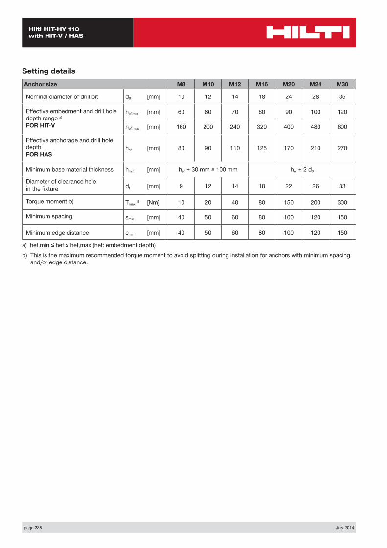
page 238 July 2014
Hilti HIT-HY 110 with HIT-V / HAS
Anchor size M8 M10 M12 M16 M20 M24 M30
Nominal diameter of drill bit d0 [mm] 10 12 14 18 24 28 35
Effective embedment and drill hole depth range a)
FOR HIT-V
hef,min [mm] 60 60 70 80 90 100 120
hef,max [mm] 160 200 240 320 400 480 600
Effective anchorage and drill hole depth FOR HAS
hef [mm] 80 90 110 125 170 210 270
Minimum base material thickness hmin [mm] hef + 30 mm ≥ 100 mm hef + 2 d0
Diameter of clearance hole in the fixture df [mm] 9 12 14 18 22 26 33
Torque moment b) Tmax b) [Nm] 10 20 40 80 150 200 300
Minimum spacing smin [mm] 40 50 60 80 100 120 150
Minimum edge distance cmin [mm] 40 50 60 80 100 120 150
a) hef,min ≤ hef ≤ hef,max (hef: embedment depth)b) This is the maximum recommended torque moment to avoid splitting during installation for anchors with minimum spacing
and/or edge distance.
Setting details
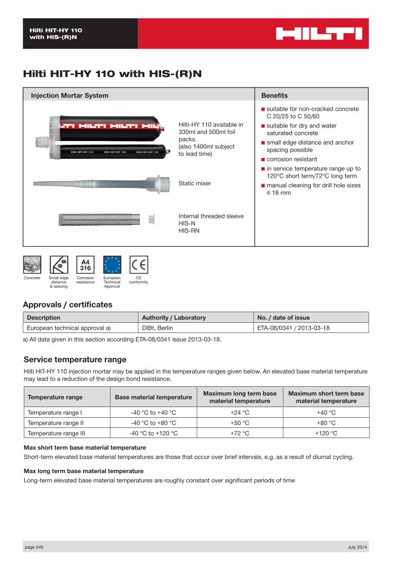
page 240 July 2014
Hilti HIT-HY 110 with HIS-(R)N
Static mixer
CE conformity
Small edge distance
& spacing
European Technical Approval
Concrete
A4 316
Corrosion resistance
Hilti HIT-HY 110 with HIS-(R)N
Injection Mortar System
Approvals / certificatesDescription Authority / Laboratory No. / date of issueEuropean technical approval a) DIBt, Berlin ETA-08/0341 / 2013-03-18
a) All data given in this section according ETA-08/0341 issue 2013-03-18.
Service temperature rangeHilti HIT-HY 110 injection mortar may be applied in the temperature ranges given below. An elevated base material temperature may lead to a reduction of the design bond resistance.
Temperature range Base material temperature Maximum long term base material temperature
Maximum short term base material temperature
Temperature range I -40 °C to +40 °C +24 °C +40 °CTemperature range II -40 °C to +80 °C +50 °C +80 °CTemperature range III -40 °C to +120 °C +72 °C +120 °C
Max short term base material temperatureShort-term elevated base material temperatures are those that occur over brief intervals, e.g. as a result of diurnal cycling.
Max long term base material temperatureLong-term elevated base material temperatures are roughly constant over significant periods of time
Benefits
■ suitable for non-cracked concrete C 20/25 to C 50/60
■ suitable for dry and water saturated concrete
■ small edge distance and anchor spacing possible
■ corrosion resistant■ in service temperature range up to
120°C short term/72°C long term■ manual cleaning for drill hole sizes
≤ 18 mm
Internal threaded sleeve HIS-N HIS-RN
Hilti-HY 110 available in 330ml and 500ml foil packs.(also 1400ml subject to lead time)

July 2014 page 241
Hilti HIT-HY 110 with HIS-(R)N
NRd = min { NRd,p, NRd,c, NRd,s } CHECK NRd ≥ NSd
Design process for typical anchor layoutsThe design values in the tables are obtained from Profis V2.4.7 in compliance with the design method according to EOTA TR 029. Design resistance according to data given in ETA-08/0341, issue 2013-03-18.■ Influence of concrete strength ■ Influence of edge distance ■ Influence of spacing
The design method is based on the following simplification:■ No different loads are acting on individual anchors (no eccentricity)
The values are valid for the anchor configuration.
For more complex fastening applications please use the anchor design software PROFIS Anchor.
STEP 1: TENSION LOADING
The design tensile resistance NRd is the lower of:
■ Combined pull-out and concrete cone resistance NRd,p = fB,p • N*Rd,p
N*Rd,p is obtained from the relevant design tables
fB,p influence of concrete strength on combined pull-out and concrete cone resistance
Concrete Strengths f’c,cyl (MPa) 20 25 32 40 50fB,p 0.95 0.97 1.00 1.02 1.04
■ Concrete cone or concrete splitting resistance NRd,c = fB • N*Rd,c
N*Rd,c is obtained from the relevant design tables
fB influence of concrete strength on concrete cone resistance
Concrete Strengths f’c,cyl (MPa) 20 25 32 40 50fB 0.79 0.87 1.00 1.11 1.22
■ Design steel resistance (tension) NRd,s
Anchor size M8 M10 M12 M16 M20
NRd,sHIS-N [kN] 17.5 30.7 44.7 80.3 74.1HIS-RN [kN] 13.9 21.9 31.6 58.8 69.2Bolt Grade 5.8 [kN] 12.0 19.3 28.0 52.7 82.0Bolt Grade 8.8 [kN] 19.3 30.7 44.7 84.0 130.7Bolt Grade A 4-70 / 316 [kN] 13.9 21.9 31.6 58.8 92.0
Note: Designer needs to check the bolt tensile resistance.
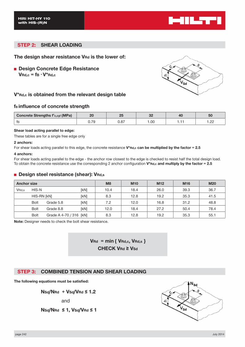
page 242 July 2014
Hilti HIT-HY 110 with HIS-(R)N
STEP 2: SHEAR LOADING
The design shear resistance VRd is the lower of:
■ Design Concrete Edge Resistance VRd,c = fB • V*Rd,c
V*Rd,c is obtained from the relevant design table
fB influence of concrete strength
Concrete Strengths f’c,cyl (MPa) 20 25 32 40 50fB 0.79 0.87 1.00 1.11 1.22
Shear load acting parallel to edge:These tables are for a single free edge only2 anchors:For shear loads acting parallel to this edge, the concrete resistance V*Rd,c can be multiplied by the factor = 2.54 anchors:For shear loads acting parallel to the edge - the anchor row closest to the edge is checked to resist half the total design load. To obtain the concrete resistance use the corresponding 2 anchor configuration V*Rd,c and multiply by the factor = 2.5
■ Design steel resistance (shear): VRd,s
Anchor size M8 M10 M12 M16 M20VRd,s HIS-N [kN] 10.4 18.4 26.0 39.3 36.7
HIS-RN [kN] [kN] 8.3 12.8 19.2 35.3 41.5Bolt Grade 5.8 [kN] 7.2 12.0 16.8 31.2 48.8Bolt Grade 8.8 [kN] 12.0 18.4 27.2 50.4 78.4Bolt Grade A 4-70 / 316 [kN] 8.3 12.8 19.2 35.3 55.1
Note: Designer needs to check the bolt shear resistance.
VRd = min { VRd,c, VRd,s } CHECK VRd ≥ VSd
STEP 3: COMBINED TENSION AND SHEAR LOADING
The following equations must be satisfied:
NSd/NRd + VSd/VRd ≤ 1.2
and
NSd/NRd ≤ 1, VSd/VRd ≤ 1
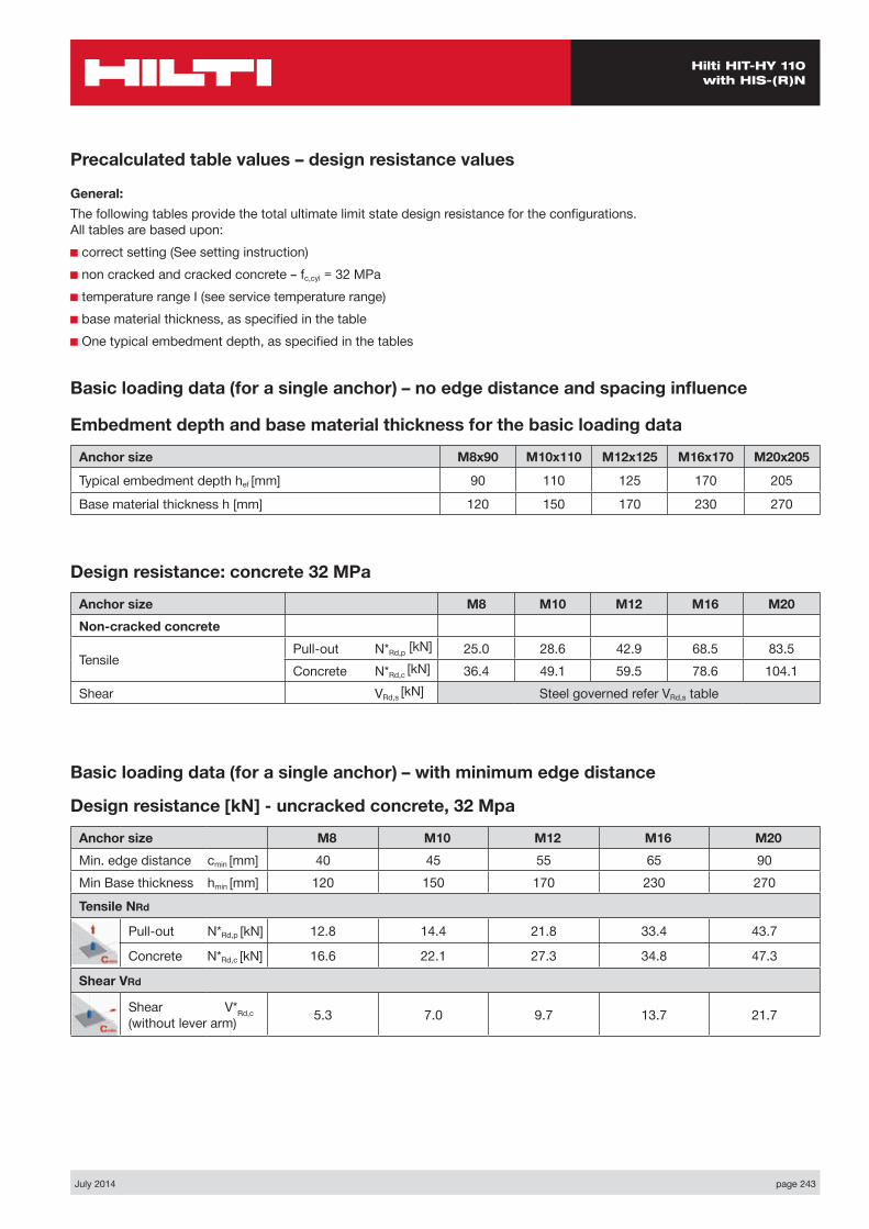
July 2014 page 243
Hilti HIT-HY 110 with HIS-(R)N
Basic loading data (for a single anchor) – no edge distance and spacing influence
Embedment depth and base material thickness for the basic loading data
Anchor size M8x90 M10x110 M12x125 M16x170 M20x205
Typical embedment depth hef [mm] 90 110 125 170 205
Base material thickness h [mm] 120 150 170 230 270
Precalculated table values – design resistance values
General:The following tables provide the total ultimate limit state design resistance for the configurations. All tables are based upon:■ correct setting (See setting instruction)■ non cracked and cracked concrete – fc,cyl = 32 MPa■ temperature range I (see service temperature range)■ base material thickness, as specified in the table■ One typical embedment depth, as specified in the tables
Design resistance: concrete 32 MPa
Anchor size M8 M10 M12 M16 M20Non-cracked concrete
Tensile Pull-out N*Rd,p [kN] 25.0 28.6 42.9 68.5 83.5Concrete N*Rd,c [kN] 36.4 49.1 59.5 78.6 104.1
Shear VRd,s [kN] Steel governed refer VRd,s table
Basic loading data (for a single anchor) – with minimum edge distance
Design resistance [kN] - uncracked concrete, 32 Mpa
Anchor size M8 M10 M12 M16 M20Min. edge distance cmin [mm] 40 45 55 65 90Min Base thickness hmin [mm] 120 150 170 230 270
Tensile NRd
Pull-out N*Rd,p [kN] 12.8 14.4 21.8 33.4 43.7
Concrete N*Rd,c [kN] 16.6 22.1 27.3 34.8 47.3
Shear VRd
Shear V*Rd,c (without lever arm) 5.3 7.0 9.7 13.7 21.7

page 244 July 2014
Hilti HIT-HY 110 with HIS-(R)N
N*
V*
S1
C
h
Two anchors Table 1: One edge influence – non cracked concrete
Design Data: fc=32 MPa
Anchor size M8 M10 M12 M16 M20Embedment Depth 90 110 125 170 205Min Slab depth 120 150 170 230 270
ANCHOR
M8Edge E (mm)
40 80 100 150 200spacings1 (mm)
tension shear tension shear tension shear tension shear tension shearN*Rd,p N*Rd,c V*Rrd,c N*Rd,p N*Rd,c V*Rrd,c N*Rd,p N*Rd,c V*Rrd,c N*Rd,p N*Rd,c V*Rrd,c N*Rd,p N*Rd,c V*Rrd,c
40 16.3 18.3 7.1 22.2 23.1 15.1 25.6 25.6 17.5 31.8 32.0 23.6 31.8 40.0 29.6
80 17.9 20.0 8.9 24.5 25.2 17.2 28.1 28.0 19.6 35.0 35.6 25.6 35.0 43.7 31.5
100 18.7 20.8 9.8 25.6 26.3 18.3 29.4 29.2 20.6 36.7 37.1 26.5 36.7 45.5 32.4
150 20.8 22.9 10.7 28.4 28.9 21.0 32.7 32.1 23.2 40.7 40.8 28.9 40.7 50.1 34.7
200 22.8 25.0 10.7 31.2 31.5 23.7 35.8 35.1 25.8 44.6 44.6 31.4 44.6 54.7 37.0
ANCHOR
M10Edge E (mm)
45 80 100 150 200spacings1 (mm)
tension shear tension shear tension shear tension shear tension shearN*Rd,p N*Rd,c V*Rrd,c N*Rd,p N*Rd,c V*Rrd,c N*Rd,p N*Rd,c V*Rrd,c N*Rd,p N*Rd,c V*Rrd,c N*Rd,p N*Rd,c V*Rrd,c
45 18.8 24.3 9.3 23.8 28.9 16.8 27.0 31.7 21.7 35.6 39.2 28.7 37.3 47.4 35.6
80 20.0 25.9 11.1 25.5 30.8 18.9 28.8 33.8 23.9 38.0 41.9 30.8 39.9 50.6 37.6
100 20.8 26.8 12.1 26.4 32.0 20.1 29.9 35.1 25.1 39.4 43.4 31.9 41.4 52.5 38.7
150 22.7 29.2 13.9 28.8 34.7 23.0 32.6 38.1 28.3 43.0 47.2 34.8 45.1 57.1 41.4
200 24.5 31.5 13.9 31.1 37.5 26.0 35.2 41.2 31.4 46.5 51.0 37.7 48.8 61.6 44.2
250 26.4 33.9 13.9 33.4 40.3 28.3 37.8 44.3 34.6 49.9 54.7 40.6 52.4 66.2 47.0
ANCHOR
M12Edge E (mm)
55 80 100 150 200spacings1 (mm)
tension shear tension shear tension shear tension shear tension shearN*Rd,p N*Rd,c V*Rrd,c N*Rd,p N*Rd,c V*Rrd,c N*Rd,p N*Rd,c V*Rrd,c N*Rd,p N*Rd,c V*Rrd,c N*Rd,p N*Rd,c V*Rrd,c
55 27.5 30.1 12.9 31.9 33.6 18.8 35.6 36.5 23.9 45.7 44.3 33.0 54.0 52.8 40.6
100 29.8 32.4 15.5 34.6 36.1 21.6 38.6 39.3 26.9 49.5 47.7 36.0 58.5 56.8 43.3
150 32.4 34.9 18.5 37.5 39.0 24.8 41.9 42.4 30.2 53.8 51.4 39.3 63.4 61.2 46.4
200 35.0 37.4 19.4 40.5 41.8 28.0 45.2 45.4 33.6 58.0 55.1 42.5 68.6 65.7 49.5
250 37.5 40.0 19.4 43.5 44.6 30.5 48.5 48.5 37.0 62.2 58.9 45.8 73.6 70.1 52.6
300 40.0 42.5 19.4 46.3 47.5 30.5 51.8 51.6 40.3 66.4 62.6 49.1 78.5 74.6 55.7

July 2014 page 245
Hilti HIT-HY 110 with HIS-(R)N
ANCHOR
M16Edge E (mm)
65 100 150 200 250spacings1 (mm)
tension shear tension shear tension shear tension shear tension shearN*Rd,p N*Rd,c V*Rrd,c N*Rd,p N*Rd,c V*Rrd,c N*Rd,p N*Rd,c V*Rrd,c N*Rd,p N*Rd,c V*Rrd,c N*Rd,p N*Rd,c V*Rrd,c
65 39.5 37.9 18.3 46.1 42.5 27.7 56.4 49.5 43.0 67.6 57.0 52.6 79.8 65.0 61.5
100 41.6 39.6 20.7 48.6 44.4 30.4 59.5 51.7 46.0 71.3 59.5 55.3 84.1 67.8 64.2
150 44.7 41.9 24.2 52.2 47.1 34.2 63.9 54.8 50.1 76.5 63.1 59.3 90.3 71.9 67.9
200 47.8 44.3 27.4 55.8 49.7 38.0 68.3 57.9 54.3 81.9 66.6 63.2 96.6 75.9 71.7
250 50.9 46.7 27.4 59.5 52.4 41.8 72.7 61.0 58.5 87.2 70.2 67.2 102.8 80.0 75.5
300 54.0 49.0 27.4 63.1 55.0 45.6 77.1 64.1 62.7 92.5 73.7 71.1 109.1 84.0 79.3
ANCHOR
M20Edge E (mm)
90 150 200 250 300spacings1 (mm)
tension shear tension shear tension shear tension shear tension shearN*Rd,p N*Rd,c V*Rrd,c N*Rd,p N*Rd,c V*Rrd,c N*Rd,p N*Rd,c V*Rrd,c N*Rd,p N*Rd,c V*Rrd,c N*Rd,p N*Rd,c V*Rrd,c
90 54.2 52.0 28.9 68.0 60.7 48.1 80.5 68.4 62.5 94.0 76.5 72.3 103.5 85.0 82.0
150 58.5 55.1 33.8 73.3 64.3 53.4 86.8 72.5 67.9 101.4 81.0 77.5 111.5 90.1 87.0
200 62.0 57.7 37.8 77.7 67.3 57.8 92.1 75.9 72.5 107.5 84.9 81.8 118.3 94.3 91.1
250 65.5 60.3 41.8 82.2 70.3 62.3 97.3 79.3 77.0 113.6 88.7 86.1 125.0 98.5 95.3
300 69.1 62.8 43.4 86.6 73.4 66.7 102.6 82.7 81.5 119.8 92.5 90.4 131.8 102.8 99.4
350 72.6 65.4 43.4 91.0 76.4 71.2 107.8 86.1 86.1 125.9 96.3 94.7 138.5 107.0 103.5

page 246 July 2014
Hilti HIT-HY 110 with HIS-(R)N
Four anchors Table 2: One edge influence – non cracked concrete
Design Data: fc=32 MPa
Anchor size M8 M10 M12 M16 M20Embedment Depth 90 110 125 170 205Min Slab depth 120 150 170 230 270
ANCHOR
M8Edge E (mm)
40 80 100 150 200spacing
s1= s2 (mm)
tension shear tension shear tension shear tension shear tension shearN*Rd,p N*Rd,c V*Rrd,c N*Rd,p N*Rd,c V*Rrd,c N*Rd,p N*Rd,c V*Rrd,c N*Rd,p N*Rd,c V*Rrd,c N*Rd,p N*Rd,c V*Rrd,c
40 22.7 21.4 14.2 30.0 26.4 20.0 34.0 29.1 22.4 41.6 36.4 28.4 41.6 44.1 34.3
80 28.9 26.7 17.8 37.1 32.4 26.8 41.7 35.5 29.1 50.2 43.8 35.0 50.2 52.5 40.8
100 32.1 29.6 19.6 41.0 35.7 30.1 45.8 39.0 32.4 54.8 47.8 38.2 54.8 57.0 44.0
150 40.9 37.4 21.4 51.2 44.5 38.2 56.7 48.3 40.5 67.1 58.5 46.2 67.1 69.1 51.8
200 50.6 46.0 21.4 62.3 54.2 46.1 68.6 58.6 48.4 80.3 70.2 54.0 80.3 82.4 59.6
ANCHOR
M10Edge E (mm)
45 80 100 150 200spacing
s1= s2 (mm)
tension shear tension shear tension shear tension shear tension shearN*Rd,p N*Rd,c V*Rrd,c N*Rd,p N*Rd,c V*Rrd,c N*Rd,p N*Rd,c V*Rrd,c N*Rd,p N*Rd,c V*Rrd,c N*Rd,p N*Rd,c V*Rrd,c
45 27.0 28.1 18.6 33.3 33.0 25.2 37.2 35.9 28.0 47.9 43.8 35.0 50.1 52.3 41.8
80 32.0 33.3 22.2 38.9 38.6 32.1 43.1 41.9 34.8 54.7 50.5 41.6 57.1 59.9 48.3
100 35.0 36.4 24.2 42.3 42.1 36.0 46.8 45.5 38.7 58.9 54.6 45.4 61.4 64.5 52.0
150 43.0 44.8 27.8 51.2 51.2 45.4 56.3 55.1 48.0 69.8 65.5 54.6 72.6 76.7 61.1
200 51.6 54.0 27.8 60.8 61.3 52.0 66.3 65.7 57.2 81.4 77.3 63.7 84.4 89.9 70.1
250 60.7 64.0 27.8 70.8 72.2 56.7 77.0 77.2 66.2 93.5 90.2 72.6 96.8 104.2 79.0
ANCHOR
M12Edge E (mm)
55 80 100 150 200spacing
s1= s2 (mm)
tension shear tension shear tension shear tension shear tension shearN*Rd,p N*Rd,c V*Rrd,c N*Rd,p N*Rd,c V*Rrd,c N*Rd,p N*Rd,c V*Rrd,c N*Rd,p N*Rd,c V*Rrd,c N*Rd,p N*Rd,c V*Rrd,c
55 38.0 35.2 25.8 43.3 38.9 30.7 47.8 42.0 33.8 59.9 50.1 41.3 69.8 59.0 48.7
100 46.4 42.3 31.0 52.3 46.5 40.4 57.3 49.9 43.3 70.7 59.0 50.6 81.6 68.9 57.9
150 56.5 51.1 37.0 63.2 55.7 49.6 68.8 59.6 53.6 83.7 69.8 60.8 95.9 80.8 67.9
200 67.5 60.5 38.8 74.9 65.7 56.0 81.2 70.1 63.7 97.8 81.5 70.7 111.3 93.7 77.7
250 79.2 70.8 38.8 87.5 76.6 61.0 94.4 81.4 73.5 112.7 94.0 80.5 127.6 107.5 87.4
300 91.6 81.8 38.8 100.7 88.3 61.0 108.3 93.5 80.6 128.4 107.4 90.1 144.6 122.3 97.0
N*
V*
S2
S1
C
h

July 2014 page 247
Hilti HIT-HY 110 with HIS-(R)N
ANCHOR
M16Edge E (mm)
65 100 150 200 250spacing
s1= s2 (mm)
tension shear tension shear tension shear tension shear tension shearN*Rd,p N*Rd,c V*Rrd,c N*Rd,p N*Rd,c V*Rrd,c N*Rd,p N*Rd,c V*Rrd,c N*Rd,p N*Rd,c V*Rrd,c N*Rd,p N*Rd,c V*Rrd,c
65 50.6 43.6 36.6 58.1 48.5 46.2 69.7 55.8 55.3 82.3 63.5 64.2 95.9 71.8 73.0
100 57.7 48.7 41.4 65.8 53.9 55.3 78.3 61.7 64.1 91.9 70.0 72.9 106.4 78.8 81.6
150 68.7 56.5 48.5 77.8 62.1 67.9 91.6 70.7 76.5 106.6 79.7 85.1 122.7 89.3 93.6
200 80.7 64.8 54.8 90.7 71.0 76.0 105.6 80.2 88.6 122.4 90.1 97.1 140.0 100.5 105.5
250 93.5 73.6 54.8 104.5 80.3 83.6 121.3 90.4 100.5 139.3 101.1 108.9 158.5 112.3 117.1
300 107.1 83.0 54.8 119.2 90.3 91.2 137.5 101.2 112.3 157.1 112.7 120.5 178.1 124.8 128.7
ANCHOR
M20Edge E (mm)
90 150 200 250 300spacing
s1= s2 (mm)
tension shear tension shear tension shear tension shear tension shearN*Rd,p N*Rd,c V*Rrd,c N*Rd,p N*Rd,c V*Rrd,c N*Rd,p N*Rd,c V*Rrd,c N*Rd,p N*Rd,c V*Rrd,c N*Rd,p N*Rd,c V*Rrd,c
90 73.5 60.5 57.8 89.6 69.7 70.4 104.3 77.7 80.1 120.0 86.2 89.7 130.9 95.1 99.2
150 88.1 70.2 67.6 106.0 80.2 87.0 122.3 89.0 96.4 139.6 98.2 105.8 151.6 107.9 115.1
200 101.2 78.8 75.6 120.8 89.5 100.4 138.4 99.0 109.7 157.2 108.9 119.0 170.2 119.2 128.2
250 115.2 87.8 83.6 136.4 99.3 113.6 155.5 109.4 122.8 175.7 120.0 132.0 189.7 131.1 141.1
300 130.0 97.3 86.8 152.9 109.6 126.7 173.4 120.4 135.7 195.2 131.7 144.8 210.2 143.5 153.8
350 145.5 107.3 86.8 170.2 120.4 142.4 192.2 131.9 148.5 215.6 144.0 157.5 231.7 156.5 166.4
Shear design: The concrete edge resistance value in this table uses all 4 anchors in shear. You will need to ensure the gap between anchor and the plate is filled. This can be achieved using the Hilti Dynamic Set. (Refer page 41 for further details)
The concrete edge resistance values have been obtained by taking the lesser of:1. First row resistance multiplied by number of rows and 2. The concrete edge resistance of the furthest row.

page 248 July 2014
Hilti HIT-HY 110 with HIS-(R)N
Setting instructions
Bore hole drillingDrill Hole to the required embedment depth with a hammer drill set inrotation-hammer mode using an appropriately sized carbide drill bit.
Bore hole cleaning Just before setting an anchor, the bore hole must be free of dust and debris.
a) Manual Cleaning (MC) for bore hole diameters d0 ≤ 18mm and bore hole depth h0 ≤ 10d
The Hilti manual pump may be used for blowing out bore holes up todiameters d0 ≤ 18 mm and embedment depths up to h0 ≤ 10d or h0 ≤ 160 mm.Blow out at least 4 times from the back of the bore hole until return airstream is free of noticeable dust
Brush 4 times with the specified brush size (brush Ø ≥ bore hole Ø) by inserting the steel brush Hilti HIT-RB to the back of the hole (if needed with extension) in a twisting motion and removing it.The brush must produce natural resistance as it enters the bore hole -- if not the brush is too small and must be replaced with the proper brush diameter.
Blow out again with manual pump at least 4 times until return air stream isfree of noticeable dust.
b) Compressed air cleaning (CAC) for all bore hole diameters d0 and all bore hole depth h0
Blow 2 times from the back of the hole (if needed with nozzle extension) over the hole length with oil-free compressed air (min. 6 bar at 6 m³/h) until return air stream is free of noticeable dust.
Brush 2 times with the specified brush size (brush Ø ≥ bore hole Ø) by inserting the steel brush Hilti HIT-RB to the back of the hole (if needed with extension) in a twisting motion and removing it.The brush must produce natural resistance as it enters the bore hole -- if not the brush is too small and must be replaced with the proper brush diameter.
Blow again with compressed air 2 times until return air stream is free of noticeable dust.
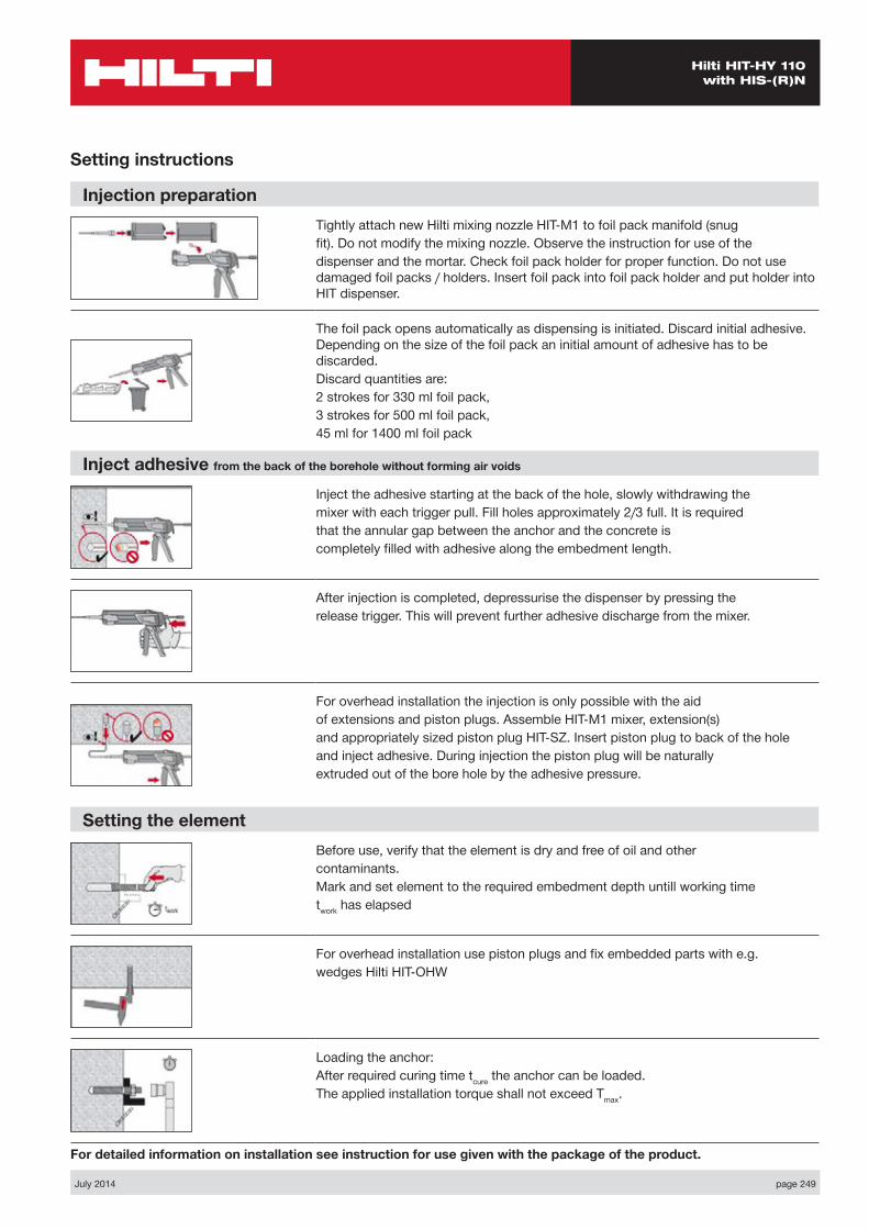
July 2014 page 249
Hilti HIT-HY 110 with HIS-(R)N
Setting instructions
Injection preparationTightly attach new Hilti mixing nozzle HIT-M1 to foil pack manifold (snugfit). Do not modify the mixing nozzle. Observe the instruction for use of thedispenser and the mortar. Check foil pack holder for proper function. Do not use damaged foil packs / holders. Insert foil pack into foil pack holder and put holder into HIT dispenser.
The foil pack opens automatically as dispensing is initiated. Discard initial adhesive. Depending on the size of the foil pack an initial amount of adhesive has to be discarded.Discard quantities are:2 strokes for 330 ml foil pack,3 strokes for 500 ml foil pack,45 ml for 1400 ml foil pack
Inject adhesive from the back of the borehole without forming air voids
Inject the adhesive starting at the back of the hole, slowly withdrawing themixer with each trigger pull. Fill holes approximately 2/3 full. It is requiredthat the annular gap between the anchor and the concrete iscompletely filled with adhesive along the embedment length.
After injection is completed, depressurise the dispenser by pressing therelease trigger. This will prevent further adhesive discharge from the mixer.
For overhead installation the injection is only possible with the aidof extensions and piston plugs. Assemble HIT-M1 mixer, extension(s)and appropriately sized piston plug HIT-SZ. Insert piston plug to back of the holeand inject adhesive. During injection the piston plug will be naturallyextruded out of the bore hole by the adhesive pressure.
Setting the elementBefore use, verify that the element is dry and free of oil and othercontaminants.Mark and set element to the required embedment depth untill working timetwork has elapsed
For overhead installation use piston plugs and fix embedded parts with e.g.wedges Hilti HIT-OHW
Loading the anchor:After required curing time tcure the anchor can be loaded.The applied installation torque shall not exceed Tmax.
For detailed information on installation see instruction for use given with the package of the product.

page 250 July 2014
Hilti HIT-HY 110 with HIS-(R)N
MaterialsMechanical properties of HIS-(R)N
Anchor size M8x90 M10x110 M12x125 M16x170 M20x205
Nominal tensile strength fuk
HIS-N [N/mm²] 490 490 460 460 460Screw 8.8 [N/mm²] 800 800 800 800 800HIS-RN [N/mm²] 700 700 700 700 700Screw A4-70 [N/mm²] 700 700 700 700 700
Yield strength fyk
HIS-N [N/mm²] 410 375 375 375 375Screw 8.8 [N/mm²] 640 640 640 640 640HIS-RN [N/mm²] 350 350 350 350 350Screw A4-70 [N/mm²] 450 450 450 450 450
Stressed cross-section AsHIS-(R)N [mm²] 51.5 108.0 169.1 256.1 237.6Screw [mm²] 36.6 58 84.3 157 245
Moment of resistance WHIS-(R)N [mm³] 145 430 840 1595 1543Screw [mm³] 31.2 62.3 109 277 541
Material quality
Part MaterialInternal threaded sleeve a) HIS-N
C-steel 1.0718 Steel galvanized ≥ 5μm
Internal threaded sleeve b) HIS-RN Stainless steel 1.4401 and 1.4571
a) related fastening screw: strength class 8.8, As > 8% Ductile steel galvanized ≥ 5μm
b) related fastening screw: strength class 70, As > 8% Ductile stainless steel 1.4401; 1.4404; 1.4578; 1.4571; 1.4439; 1.4362
Anchor dimensions
Anchor size M8 M10 M12 M16 M20Internal threaded sleeve HIS-(R)N M8x90 M10x110 M12x125 M16x170 M20x205Anchor embedment depth [mm] 90 110 125 170 205
Setting
Installation equipmentAnchor size M8x90 M10x110 M12x125 M16x170 M20x205Rotary hammer TE 2 – TE 30 TE 40 – TE 70Other tools compressed air gun or blow out pump, set of cleaning brushes, dispenser
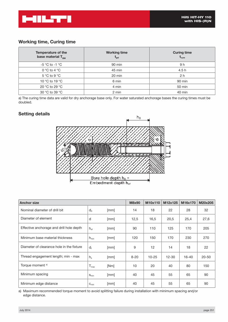
July 2014 page 251
Hilti HIT-HY 110 with HIS-(R)N
Working time, Curing time
Temperature of the base material TBM
Working time tgel
Curing time tcure
-5 °C to -1 °C 90 min 9 h0 °C to 4 °C 45 min 4.5 h5 °C to 9 °C 20 min 2 h
10 °C to 19 °C 6 min 90 min20 °C to 29 °C 4 min 50 min30 °C to 39 °C 2 min 40 min
a) The curing time data are valid for dry anchorage base only. For water saturated anchorage bases the curing times must be doubled.
Setting details
Anchor size M8x90 M10x110 M12x125 M16x170 M20x205
Nominal diameter of drill bit d0 [mm] 14 18 22 28 32
Diameter of element d [mm] 12,5 16,5 20,5 25,4 27,6
Effective anchorage and drill hole depth hef [mm] 90 110 125 170 205
Minimum base material thickness hmin [mm] 120 150 170 230 270
Diameter of clearance hole in the fixture df [mm] 9 12 14 18 22
Thread engagement length; min - max hs [mm] 8-20 10-25 12-30 16-40 20-50
Torque moment a) Tmax [Nm] 10 20 40 80 150
Minimum spacing smin [mm] 40 45 55 65 90
Minimum edge distance cmin [mm] 40 45 55 65 90
a) Maximum recommended torque moment to avoid splitting failure during installation with minimum spacing and/or edge distance.
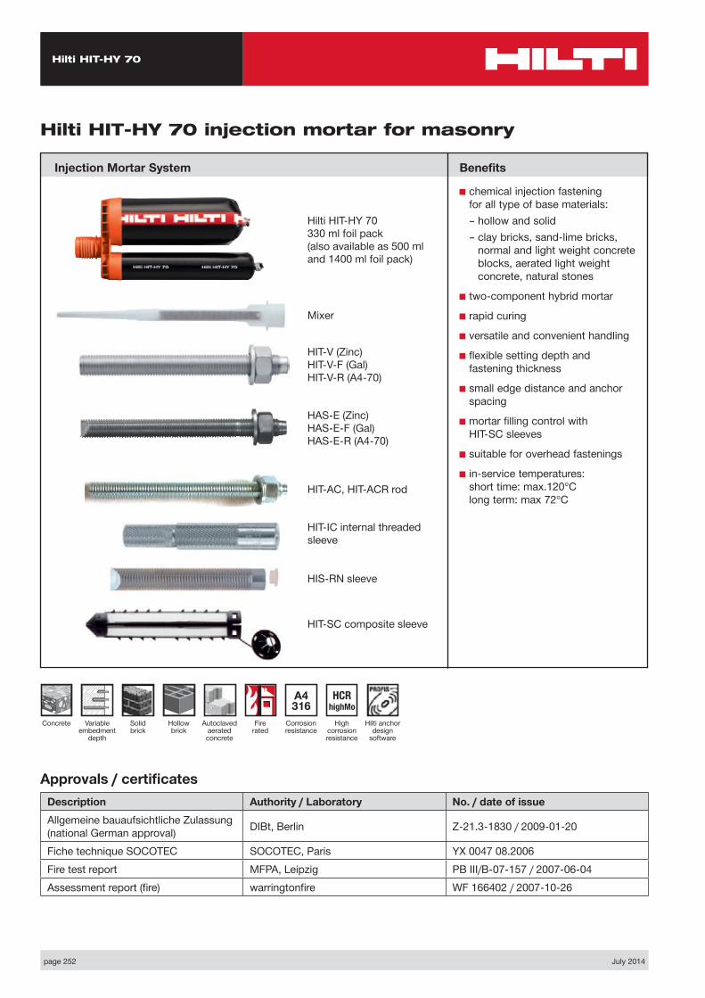
Hilti HIT-HY 70
page 252 July 2014
Injection Mortar System
Hilti anchor design
software
Concrete
Hilti HIT-HY 70 injection mortar for masonry
Benefits
■ chemical injection fastening for all type of base materials:
– hollow and solid – clay bricks, sand-lime bricks,
normal and light weight concrete blocks, aerated light weight concrete, natural stones
■ two-component hybrid mortar
■ rapid curing
■ versatile and convenient handling
■ flexible setting depth and fastening thickness
■ small edge distance and anchor spacing
■ mortar filling control with HIT-SC sleeves
■ suitable for overhead fastenings
■ in-service temperatures: short time: max.120°C long term: max 72°C
Approvals / certificatesDescription Authority / Laboratory No. / date of issueAllgemeine bauaufsichtliche Zulassung (national German approval) DIBt, Berlin Z-21.3-1830 / 2009-01-20
Fiche technique SOCOTEC SOCOTEC, Paris YX 0047 08.2006Fire test report MFPA, Leipzig PB III/B-07-157 / 2007-06-04Assessment report (fire) warringtonfire WF 166402 / 2007-10-26
A4 316
Corrosion resistance
HCR highMo
High corrosion resistance
Variable embedment
depth
Autoclaved aerated concrete
Hollow brick
Solid brick
Fire rated
Hilti HIT-HY 70 330 ml foil pack (also available as 500 ml and 1400 ml foil pack)
HIT-AC, HIT-ACR rod
HIT-IC internal threaded sleeve
HIS-RN sleeve
HIT-SC composite sleeve
Mixer
HIT-V (Zinc)HIT-V-F (Gal)HIT-V-R (A4-70)
HAS-E (Zinc)HAS-E-F (Gal)HAS-E-R (A4-70)
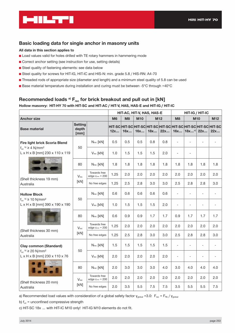
Hilti HIT-HY 70
July 2014 page 253
Recommended loads a) Frec for brick breakout and pull out in [kN] Hollow masonry: HIT-HY 70 with HIT-SC and HIT-AC / HIT-V, HAS, HAS-E and HIT-IG / HIT-IC
HIT-AC, HIT-V, HAS, HAS-E HIT-IG / HIT-ICAnchor size M6 M8 M10 M12 M8 M10 M12
Base materialSetting depth [mm]
HIT-SC 12x…
HIT-SC 16x…
HIT-SC 16x…
HIT-SC 18x…
HIT-SC 22x…
HIT-SC 16x…
HIT-SC 18x…c)
HIT-SC 22x…
HIT-SC 22x…
Fire light brick Scoria Blendfuc b) ≥ 4 N/mm²L x H x B [mm] 230 x 110 x 119
(Shell thickness 19 mm)Australia
50Nrec [kN] 0.5 0.5 0.5 0.8 0.8 - - - -
Vrec [kN] 1.0 1.5 1.5 1.5 2.0 - -
80 Nrec [kN] 1.8 1.8 1.8 1.8 1.8 1.8 1.8 1.8 1.8
Vrec [kN]
Towards free edge cmin = 200 1.25 2.0 2.0 2.0 2.0 2.0 2.0 2.0 2.0
No free edges 1.25 2.5 2.8 3.0 3.0 2.5 2.8 2.8 3.0
Hollow Blockfuc b) ≥ 10 N/mm²L x H x B [mm] 390 x 190 x 190
(Shell thickness 30 mm)Australia
50Nrec [kN] 0.6 0.6 0.6 0.6 0.6 - - - -
Vrec [kN] 1.0 1.5 1.5 1.5 2.0 - - - -
80 Nrec [kN] 0.6 0.9 0.9 1.7 1.7 0.9 1.7 1.7 1.7
Vrec [kN]
Towards free edge cmin = 200 1.25 2.0 2.0 2.0 2.0 2.0 2.0 2.0 2.0
No free edges 1.25 2.5 2.8 3.0 3.0 2.5 2.8 2.8 3.0
Clay common (Standard)fuc b) ≥ 20 N/mm²L x H x B [mm] 230 x 110 x 76
(Shell thickness 20 mm)Australia
50Nrec [kN] 1.5 1.5 1.5 1.5 1.5 - - - -
Vrec [kN] 2.0 2.0 2.0 2.0 2.0 - - - -
80 Nrec [kN] 2.0 3.0 3.0 3.0 4.0 3.0 4.0 4.0 4.0
Vrec [kN]
Towards free edge cmin = 200 2.0 2.0 2.0 2.0 2.0 2.0 2.0 2.0 2.0
No free edges 2.0 3.5 5.5 7.5 7.5 3.5 5.5 5.5 7.5
a) Recommended load values with consideration of a global safety factor γglobal =3.0: Frec = FRk / γglobal
b) fuc = unconfined compressive strengthc) HIT-SC 18x … with HIT-IC M10 only! HIT-IG M10 elements do not fit.
Basic loading data for single anchor in masonry unitsAll data in this section applies to■ Load values valid for holes drilled with TE rotary hammers in hammering mode■ Correct anchor setting (see instruction for use, setting details)■ Steel quality of fastening elements: see data below■ Steel quality for screws for HIT-IG, HIT-IC and HIS-N: min. grade 5.8 / HIS-RN: A4-70■ Threaded rods of appropriate size (diameter and length) and a minimum steel quality of 5.8 can be used■ Base material temperature during installation and curing must be between -5°C through +40°C
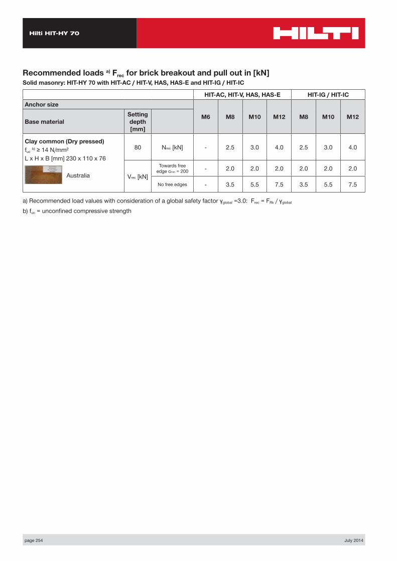
Hilti HIT-HY 70
page 254 July 2014
Recommended loads a) Frec for brick breakout and pull out in [kN] Solid masonry: HIT-HY 70 with HIT-AC / HIT-V, HAS, HAS-E and HIT-IG / HIT-IC
HIT-AC, HIT-V, HAS, HAS-E HIT-IG / HIT-ICAnchor size
M6 M8 M10 M12 M8 M10 M12Base material
Setting depth [mm]
Clay common (Dry pressed)fuc b) ≥ 14 N/mm²L x H x B [mm] 230 x 110 x 76 Australia
80 Nrec [kN] - 2.5 3.0 4.0 2.5 3.0 4.0
Vrec [kN]
Towards free edge cmin = 200 - 2.0 2.0 2.0 2.0 2.0 2.0
No free edges - 3.5 5.5 7.5 3.5 5.5 7.5
a) Recommended load values with consideration of a global safety factor γglobal =3.0: Frec = FRk / γglobal
b) fuc = unconfined compressive strength
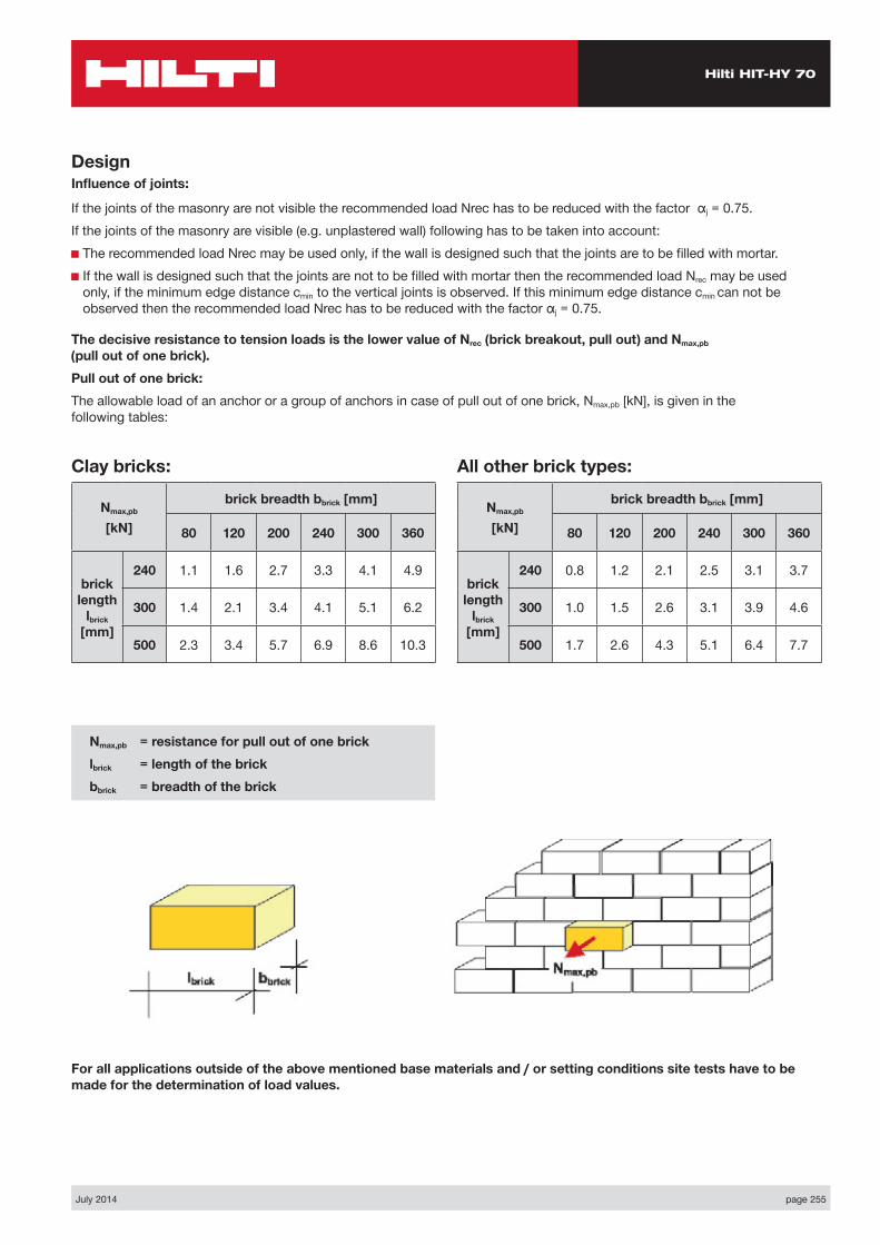
Hilti HIT-HY 70
July 2014 page 255
DesignInfluence of joints:
If the joints of the masonry are not visible the recommended load Nrec has to be reduced with the factor αj = 0.75.If the joints of the masonry are visible (e.g. unplastered wall) following has to be taken into account:■ The recommended load Nrec may be used only, if the wall is designed such that the joints are to be filled with mortar.■ If the wall is designed such that the joints are not to be filled with mortar then the recommended load Nrec may be used
only, if the minimum edge distance cmin to the vertical joints is observed. If this minimum edge distance cmin can not be observed then the recommended load Nrec has to be reduced with the factor αj = 0.75.
The decisive resistance to tension loads is the lower value of Nrec (brick breakout, pull out) and Nmax,pb (pull out of one brick).Pull out of one brick:The allowable load of an anchor or a group of anchors in case of pull out of one brick, Nmax,pb [kN], is given in the following tables:
For all applications outside of the above mentioned base materials and / or setting conditions site tests have to be made for the determination of load values.
Nmax,pb = resistance for pull out of one bricklbrick = length of the brick bbrick = breadth of the brick
Clay bricks:
Nmax,pb
[kN]
brick breadth bbrick [mm]
80 120 200 240 300 360
brick length
lbrick [mm]
240 1.1 1.6 2.7 3.3 4.1 4.9
300 1.4 2.1 3.4 4.1 5.1 6.2
500 2.3 3.4 5.7 6.9 8.6 10.3
All other brick types:
Nmax,pb
[kN]
brick breadth bbrick [mm]
80 120 200 240 300 360
brick length
lbrick [mm]
240 0.8 1.2 2.1 2.5 3.1 3.7
300 1.0 1.5 2.6 3.1 3.9 4.6
500 1.7 2.6 4.3 5.1 6.4 7.7
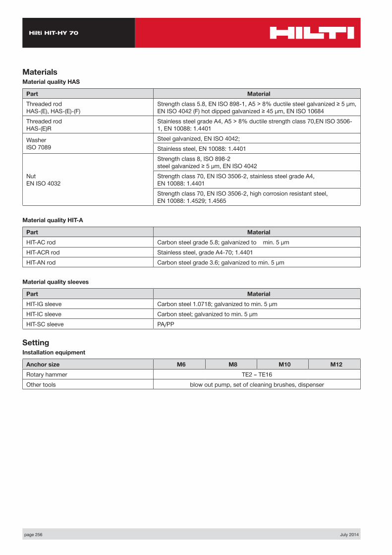
Hilti HIT-HY 70
page 256 July 2014
MaterialsMaterial quality HAS
Part MaterialThreaded rod HAS-(E), HAS-(E)-(F)
Strength class 5.8, EN ISO 898-1, A5 > 8% ductile steel galvanized ≥ 5 µm, EN ISO 4042 (F) hot dipped galvanized ≥ 45 µm, EN ISO 10684
Threaded rod HAS-(E)R
Stainless steel grade A4, A5 > 8% ductile strength class 70,EN ISO 3506-1, EN 10088: 1.4401
Washer ISO 7089
Steel galvanized, EN ISO 4042;Stainless steel, EN 10088: 1.4401
Nut EN ISO 4032
Strength class 8, ISO 898-2 steel galvanized ≥ 5 µm, EN ISO 4042Strength class 70, EN ISO 3506-2, stainless steel grade A4, EN 10088: 1.4401Strength class 70, EN ISO 3506-2, high corrosion resistant steel, EN 10088: 1.4529; 1.4565
Material quality HIT-A
Part MaterialHIT-AC rod Carbon steel grade 5.8; galvanized to min. 5 µmHIT-ACR rod Stainless steel, grade A4-70; 1.4401HIT-AN rod Carbon steel grade 3.6; galvanized to min. 5 µm
Material quality sleeves
Part MaterialHIT-IG sleeve Carbon steel 1.0718; galvanized to min. 5 µmHIT-IC sleeve Carbon steel; galvanized to min. 5 µmHIT-SC sleeve PA/PP
SettingInstallation equipment
Anchor size M6 M8 M10 M12Rotary hammer TE2 – TE16Other tools blow out pump, set of cleaning brushes, dispenser
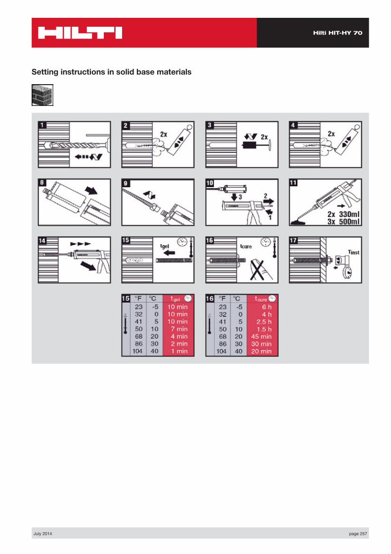
Hilti HIT-HY 70
July 2014 page 257
Setting instructions in solid base materials
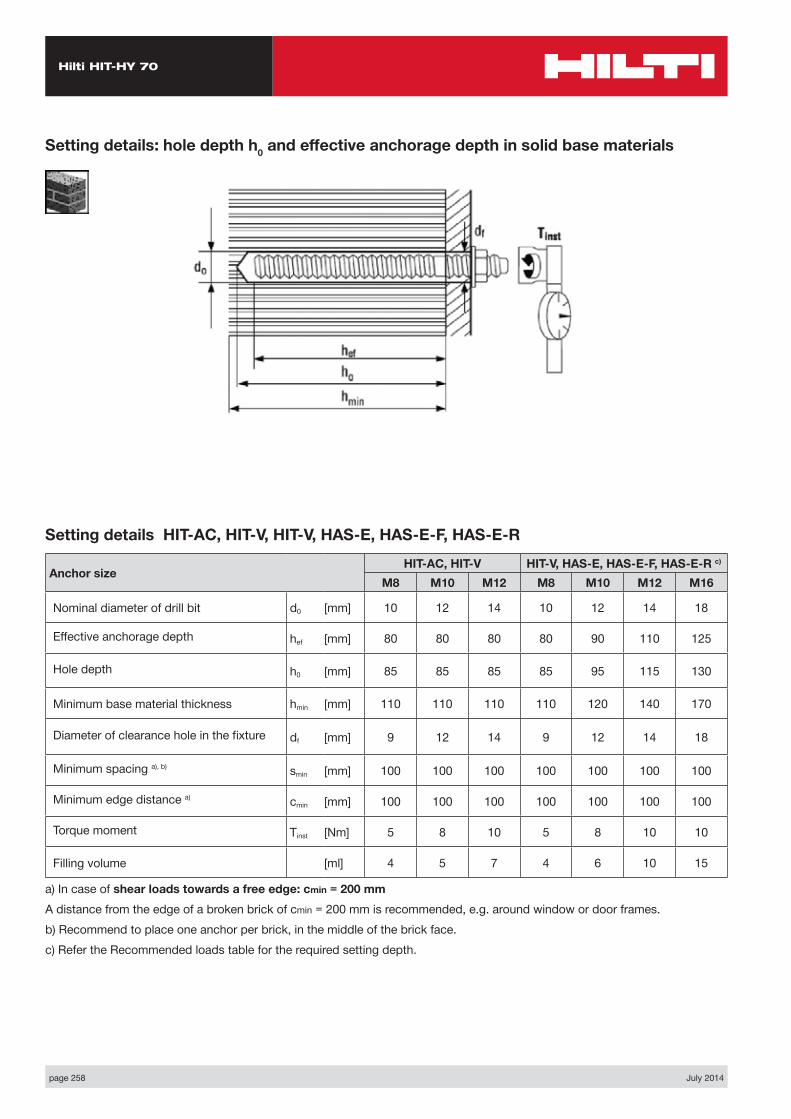
Hilti HIT-HY 70
page 258 July 2014
Setting details: hole depth h0 and effective anchorage depth in solid base materials
Setting details HIT-AC, HIT-V, HIT-V, HAS-E, HAS-E-F, HAS-E-R
Anchor sizeHIT-AC, HIT-V HIT-V, HAS-E, HAS-E-F, HAS-E-R c)
M8 M10 M12 M8 M10 M12 M16
Nominal diameter of drill bit d0 [mm] 10 12 14 10 12 14 18
Effective anchorage depth hef [mm] 80 80 80 80 90 110 125
Hole depth h0 [mm] 85 85 85 85 95 115 130
Minimum base material thickness hmin [mm] 110 110 110 110 120 140 170
Diameter of clearance hole in the fixture df [mm] 9 12 14 9 12 14 18
Minimum spacing a), b) smin [mm] 100 100 100 100 100 100 100
Minimum edge distance a) cmin [mm] 100 100 100 100 100 100 100
Torque moment Tinst [Nm] 5 8 10 5 8 10 10
Filling volume [ml] 4 5 7 4 6 10 15
a) In case of shear loads towards a free edge: cmin = 200 mmA distance from the edge of a broken brick of cmin = 200 mm is recommended, e.g. around window or door frames.b) Recommend to place one anchor per brick, in the middle of the brick face.c) Refer the Recommended loads table for the required setting depth.
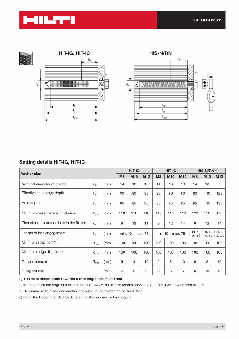
Hilti HIT-HY 70
July 2014 page 259
HIT-IG, HIT-IC HIS-N/RN
Setting details HIT-IG, HIT-IC
Anchor sizeHIT-IG HIT-IC HIS-N/RN c)
M8 M10 M12 M8 M10 M12 M8 M10 M12
Nominal diameter of drill bit d0 [mm] 14 18 18 14 16 18 14 18 22
Effective anchorage depth hef [mm] 80 80 80 80 80 80 90 110 125
Hole depth h0 [mm] 85 85 85 85 85 85 95 115 130
Minimum base material thickness hmin [mm] 110 110 110 110 110 110 120 150 170
Diameter of clearance hole in the fixture df [mm] 9 12 14 9 12 14 9 12 14
Length of bolt engagement hs [mm] min. 10 – max. 75 min. 10 – max. 75 min. 8 max.20
min. 10 max.25
min. 12 max.30
Minimum spacing a), b) smin [mm] 100 100 100 100 100 100 100 100 100
Minimum edge distance a) cmin [mm] 100 100 100 100 100 100 100 100 100
Torque moment Tinst [Nm] 5 8 10 5 8 10 5 8 10
Filling volume [ml] 6 6 6 6 6 6 6 10 16
a) In case of shear loads towards a free edge: cmin = 200 mmA distance from the edge of a broken brick of cmin = 200 mm is recommended, e.g. around window or door frames.b) Recommend to place one anchor per brick, in the middle of the brick face.c) Refer the Recommended loads table for the required setting depth.
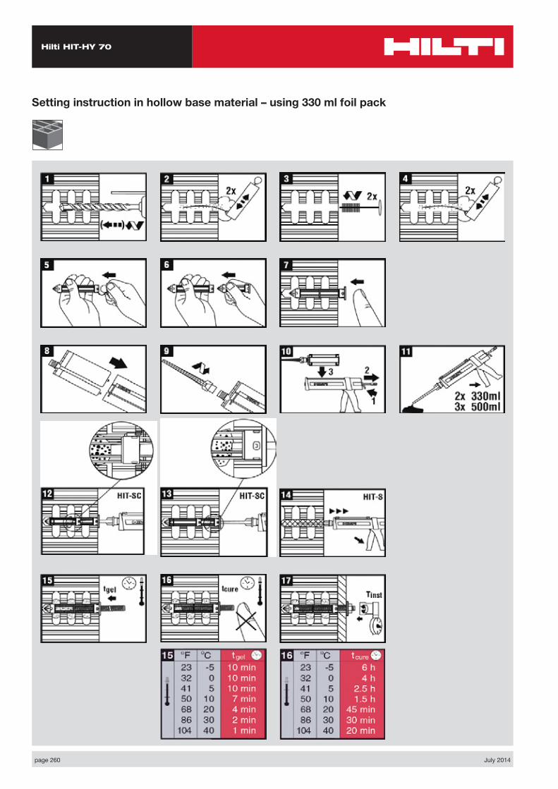
Hilti HIT-HY 70
page 260 July 2014
Setting instruction in hollow base material – using 330 ml foil pack
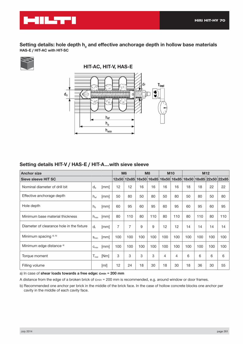
Hilti HIT-HY 70
July 2014 page 261
Setting details: hole depth h0 and effective anchorage depth in hollow base materialsHAS-E / HIT-AC with HIT-SC
HIT-AC, HIT-V, HAS-E
Setting details HIT-V / HAS-E / HIT-A…with sieve sleeve
Anchor size M6 M8 M10 M12Sieve sleeve HIT SC 12x50 12x85 16x50 16x85 16x50 16x85 18x50 18x85 22x50 22x85
Nominal diameter of drill bit d0 [mm] 12 12 16 16 16 16 18 18 22 22
Effective anchorage depth hef [mm] 50 80 50 80 50 80 50 80 50 80
Hole depth h0 [mm] 60 95 60 95 60 95 60 95 60 95
Minimum base material thickness hmin [mm] 80 110 80 110 80 110 80 110 80 110
Diameter of clearance hole in the fixture df [mm] 7 7 9 9 12 12 14 14 14 14
Minimum spacing a), b) smin [mm] 100 100 100 100 100 100 100 100 100 100
Minimum edge distance a) cmin [mm] 100 100 100 100 100 100 100 100 100 100
Torque moment Tinst [Nm] 3 3 3 3 4 4 6 6 6 6
Filling volume [ml] 12 24 18 30 18 30 18 36 30 55
a) In case of shear loads towards a free edge: cmin = 200 mmA distance from the edge of a broken brick of cmin = 200 mm is recommended, e.g. around window or door frames.b) Recommended one anchor per brick in the middle of the brick face. In the case of hollow concrete blocks one anchor per
cavity in the middle of each cavity face.
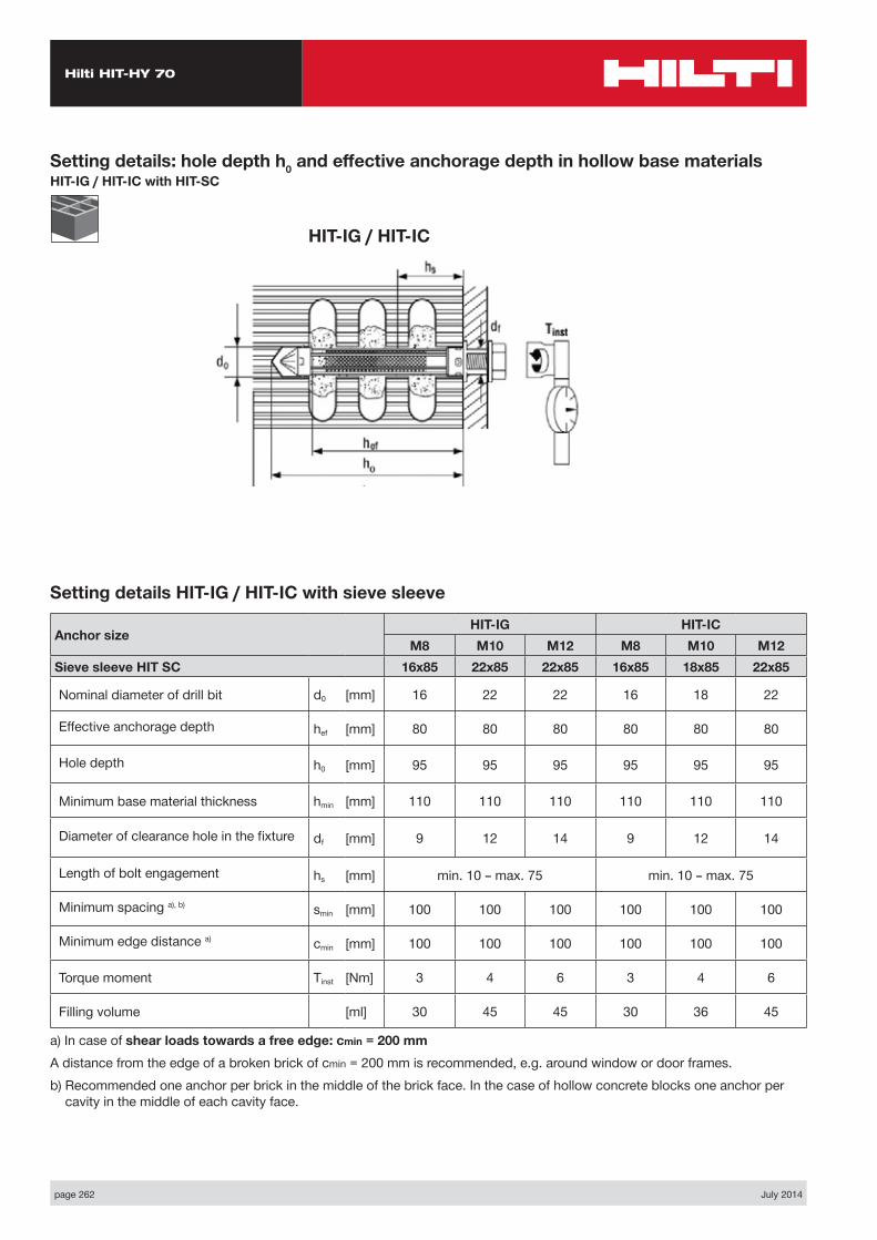
Hilti HIT-HY 70
page 262 July 2014
Setting details: hole depth h0 and effective anchorage depth in hollow base materialsHIT-IG / HIT-IC with HIT-SC
HIT-IG / HIT-IC
Setting details HIT-IG / HIT-IC with sieve sleeve
Anchor sizeHIT-IG HIT-IC
M8 M10 M12 M8 M10 M12Sieve sleeve HIT SC 16x85 22x85 22x85 16x85 18x85 22x85
Nominal diameter of drill bit d0 [mm] 16 22 22 16 18 22
Effective anchorage depth hef [mm] 80 80 80 80 80 80
Hole depth h0 [mm] 95 95 95 95 95 95
Minimum base material thickness hmin [mm] 110 110 110 110 110 110
Diameter of clearance hole in the fixture df [mm] 9 12 14 9 12 14
Length of bolt engagement hs [mm] min. 10 – max. 75 min. 10 – max. 75
Minimum spacing a), b) smin [mm] 100 100 100 100 100 100
Minimum edge distance a) cmin [mm] 100 100 100 100 100 100
Torque moment Tinst [Nm] 3 4 6 3 4 6
Filling volume [ml] 30 45 45 30 36 45
a) In case of shear loads towards a free edge: cmin = 200 mmA distance from the edge of a broken brick of cmin = 200 mm is recommended, e.g. around window or door frames.b) Recommended one anchor per brick in the middle of the brick face. In the case of hollow concrete blocks one anchor per
cavity in the middle of each cavity face.
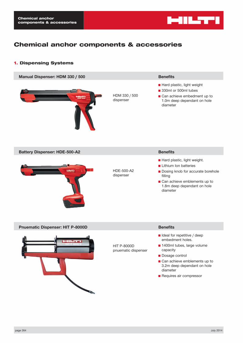
Chemical anchor components & accessories
page 264 July 2014
Chemical anchor components & accessories
1. Dispensing Systems
Manual Dispenser: HDM 330 / 500
Battery Dispenser: HDE-500-A2
Pnuematic Dispenser: HIT P-8000D
Benefits
■ Hard plastic, light weight■ 330ml or 500ml tubes■ Can achieve embedment up to
1.0m deep dependant on hole diameter
Benefits
■ Hard plastic, light weight.■ Lithium Ion batteries■ Dosing knob for accurate borehole
filling■ Can achieve emblements up to
1.8m deep dependant on hole diameter
Benefits
■ Ideal for repetitive / deep embedment holes.
■ 1400ml tubes, large volume capacity
■ Dosage control■ Can achieve emblements up to
3.2m deep dependant on hole diameter
■ Requires air compressor
HDM 330 / 500 dispenser
HDE-500-A2 dispenser
HIT P-8000D pnuematic dispenser
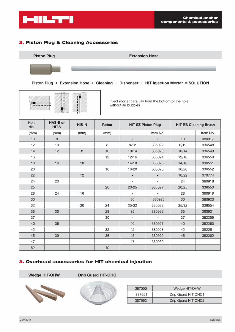
Chemical anchor components & accessories
July 2014 page 265
2. Piston Plug & Cleaning Accessories
3. Overhead accessories for HIT chemical injection
Piston Plug
Wedge HIT-OHW
Extension Hose
Drip Guard HIT-OHC
Piston Plug + Extension Hose + Cleaning + Dispenser + HIT Injection Mortar = SOLUTION
Inject mortar carefully from the bottom of the hole without air bubbles
Hole dia.
HAS-E or HIT-V HIS-N Rebar HIT-SZ Piston Plug HIT-RB Cleaning Brush
(mm) (mm) (mm) (mm) Item No. Item No.10 8 - - 10 38091712 10 8 8/12 335022 8/12 33654814 12 8 10 10/14 335023 10/14 33654916 12 12/16 335024 12/16 33655018 16 10 14/18 335025 14/18 33655120 16 16/20 335026 16/20 33655222 12 - - 18/22 37077424 20 - - 24 38091825 20 20/25 335027 20/25 33655328 24 16 - - 28 38091930 30 380925 30 38092032 20 24 25/32 335028 25/32 33655435 30 28 35 380926 35 38092137 30 - - 37 38225940 36 40 380927 40 38226042 32 42 380928 42 38226145 39 36 45 380929 45 38226247 47 380930 - -52 40 - - - -
387550 Wedge HIT-OHW 387551 Drip Guard HIT-OHC1387552 Drip Guard HIT OHC2

Chemical anchor components & accessories
page 266 July 2014
Max. fastenable height +
anchorage depth
Typical embed-
ment depth (mm)
Rod length (mm)
Drill bit dia.
(mm)
Package contents
(pcs)Ordering designation
Item no.
65 80 80 10 20 HIT-V M8 × 80 38705495 80 110 10 20 HIT-V M8 × 110 387055135 80 150 10 20 HIT-V M8 × 150** 38705678 90 95 12 10 HIT-V M10 × 95 38705798 90 115 12 10 HIT-V M10 × 115 387146113 90 130 12 10 HIT-V M10 × 130 387058173 90 190 12 10 HIT-V M10 × 190** 38705991 110 110 14 10 HIT-V M12 × 110 387060101 110 120 14 10 HIT-V M12 × 120 387147131 110 150 14 10 HIT-V M12 × 150 387061201 110 220 14 10 HIT-V M12 × 220** 387062261 110 280 14 10 HIT-V M12 × 280** 387063127 125 150 18 5 HIT-V M16 × 150 387064177 125 200 18 5 HIT-V M16 × 200 387065277 125 300 18 5 HIT-V M16 × 300 387066357 125 380 18 5 HIT-V M16 × 380** 387067153 170 180 24 10 HIT-V M20 × 180 387068233 170 260 24 10 HIT-V M20 × 260 387069353 170 380 24 10 HIT-V M20 × 380 387070453 170 480 24 10 HIT-V M20 × 480 387071268 210 300 28 5 HIT-V M24 × 300 387072418 210 450 28 5 HIT-V M24 × 450 387073
* Depending on the type of HIT injectable mortar used** 8.8 grade steel
Max. fastenable height +
anchorage depth
Typical embed-
ment depth (mm)
Rod length (mm)
Drill bit dia.
(mm)
Package contents
(pcs)Ordering designation
Item no.
65 80 80 10 20 HIT-V-R M8 × 80 38707495 80 110 10 20 HIT-V-R M8 × 110 387075135 80 150 10 20 HIT-V-R M8 × 150 38707678 90 95 12 10 HIT-V-R M10 × 95 38707798 90 115 12 10 HIT-V-R M10 × 115 387148
113 90 130 12 10 HIT-V-R M10 × 130 387078173 90 190 12 10 HIT-V-R M10 × 190 38707991 110 110 14 10 HIT-V-R M12 × 110 387080101 110 120 14 10 HIT-V-R M12 × 120 387149131 110 150 14 10 HIT-V-R M12 × 150 387081201 110 220 14 10 HIT-V-R M12 × 220 387082261 110 280 14 10 HIT-V-R M12 × 280 387083127 125 150 18 5 HIT-V-R M16 × 150 387084177 125 200 18 5 HIT-V-R M16 × 200 387085277 125 300 18 5 HIT-V-R M16 × 300 387086357 125 380 18 5 HIT-V-R M16 × 380 387087153 170 180 24 10 HIT-V-R M20 × 180 387150233 170 260 24 10 HIT-V-R M20 × 260 387088353 170 380 24 10 HIT-V-R M20 × 380 387089453 170 480 24 10 HIT-V-R M20 × 480 387151268 210 300 28 5 HIT-V-R M24 × 300 387152418 210 450 28 5 HIT-V-R M24 × 450 387153
HIT-V threaded anchor rodA universal anchor rod for use with all HIT injectable mortars, enabling flexible embedment depth.
HIT-V-F threaded anchor rod Universal anchor rod for use with all HIT injectable mortars, enabling flexible embedment depth. Hot dip-galvanized version (complete with nut and washer), 5.8 grade steel.Available in same sizes and steel strength grade as HIT-V (zinc plated).
HIT-V threaded anchor rod A universal anchor rod for use with all HIT injectable mortars, enabling flexible embedment depth. Zinc plated version (complete with nut and washer), 5.8 grade steel.
HIT-VR threaded anchor rod A universal anchor rod for use with all HIT injectable mortars, enabling flexible embedment depth. Stainless steel version (complete with nut and washer), A4-70 grade steel.
CE conformity
HIT-HY 150 MAX ETA-08/0352HIT-RE 500 ETA-04/0027
HIT-RE 500-SD ETA-07/0260
4. Threaded Anchor Rods and Internally Threaded Sleeves
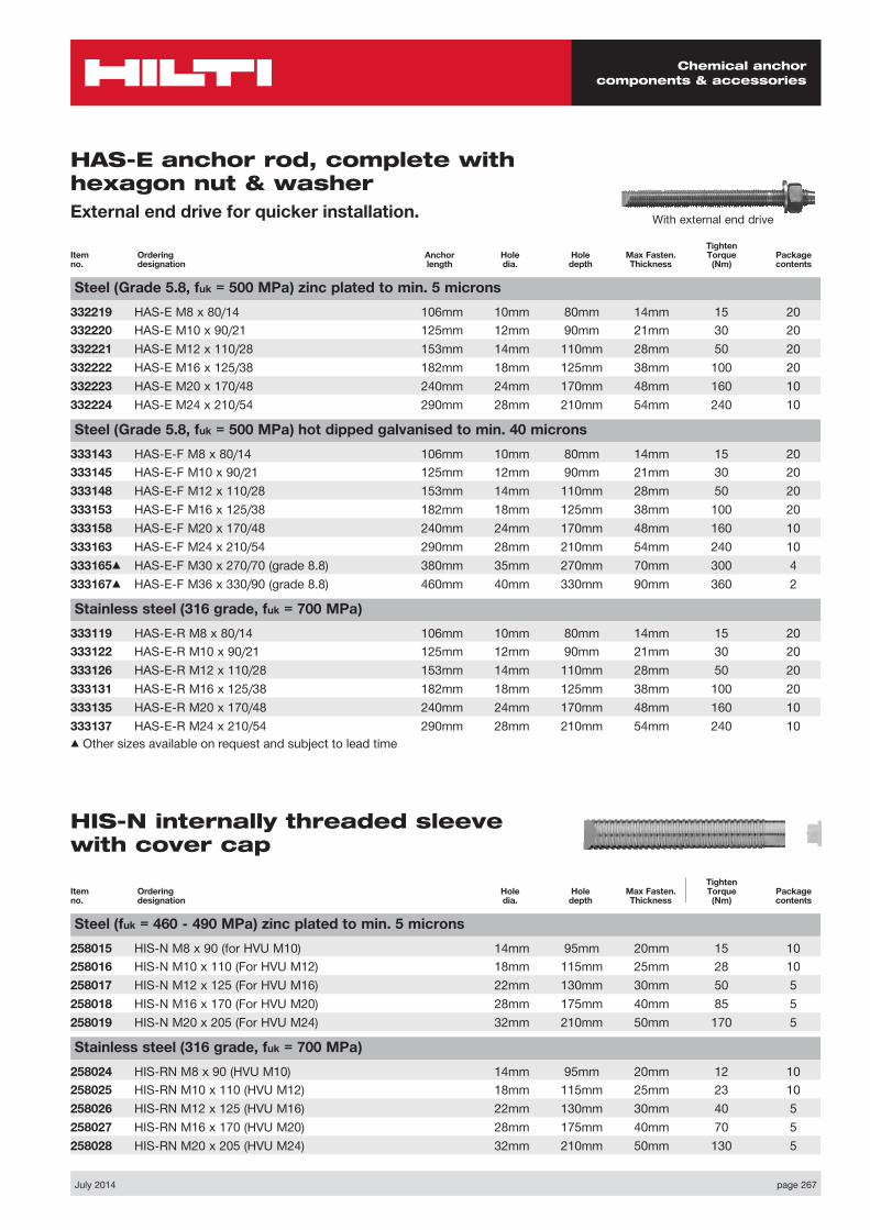
Chemical anchor components & accessories
July 2014 page 267
Item no.
Ordering designation
Anchor length
Hole dia.
Hole depth
Max Fasten. Thickness
Tighten Torque
(Nm)Package contents
Steel (Grade 5.8, fuk = 500 MPa) zinc plated to min. 5 microns332219 HAS-E M8 x 80/14 106mm 10mm 80mm 14mm 15 20332220 HAS-E M10 x 90/21 125mm 12mm 90mm 21mm 30 20332221 HAS-E M12 x 110/28 153mm 14mm 110mm 28mm 50 20332222 HAS-E M16 x 125/38 182mm 18mm 125mm 38mm 100 20332223 HAS-E M20 x 170/48 240mm 24mm 170mm 48mm 160 10332224 HAS-E M24 x 210/54 290mm 28mm 210mm 54mm 240 10
Steel (Grade 5.8, fuk = 500 MPa) hot dipped galvanised to min. 40 microns333143 HAS-E-F M8 x 80/14 106mm 10mm 80mm 14mm 15 20333145 HAS-E-F M10 x 90/21 125mm 12mm 90mm 21mm 30 20333148 HAS-E-F M12 x 110/28 153mm 14mm 110mm 28mm 50 20333153 HAS-E-F M16 x 125/38 182mm 18mm 125mm 38mm 100 20333158 HAS-E-F M20 x 170/48 240mm 24mm 170mm 48mm 160 10333163 HAS-E-F M24 x 210/54 290mm 28mm 210mm 54mm 240 10333165▲ HAS-E-F M30 x 270/70 (grade 8.8) 380mm 35mm 270mm 70mm 300 4333167▲ HAS-E-F M36 x 330/90 (grade 8.8) 460mm 40mm 330mm 90mm 360 2
Stainless steel (316 grade, fuk = 700 MPa)333119 HAS-E-R M8 x 80/14 106mm 10mm 80mm 14mm 15 20333122 HAS-E-R M10 x 90/21 125mm 12mm 90mm 21mm 30 20333126 HAS-E-R M12 x 110/28 153mm 14mm 110mm 28mm 50 20333131 HAS-E-R M16 x 125/38 182mm 18mm 125mm 38mm 100 20333135 HAS-E-R M20 x 170/48 240mm 24mm 170mm 48mm 160 10333137 HAS-E-R M24 x 210/54 290mm 28mm 210mm 54mm 240 10▲ Other sizes available on request and subject to lead time
Item no.
Ordering designation
Hole dia.
Hole depth
Max Fasten. Thickness
Tighten Torque
(Nm)Package contents
Steel (fuk = 460 - 490 MPa) zinc plated to min. 5 microns258015 HIS-N M8 x 90 (for HVU M10) 14mm 95mm 20mm 15 10258016 HIS-N M10 x 110 (For HVU M12) 18mm 115mm 25mm 28 10258017 HIS-N M12 x 125 (For HVU M16) 22mm 130mm 30mm 50 5258018 HIS-N M16 x 170 (For HVU M20) 28mm 175mm 40mm 85 5258019 HIS-N M20 x 205 (For HVU M24) 32mm 210mm 50mm 170 5
Stainless steel (316 grade, fuk = 700 MPa)258024 HIS-RN M8 x 90 (HVU M10) 14mm 95mm 20mm 12 10258025 HIS-RN M10 x 110 (HVU M12) 18mm 115mm 25mm 23 10258026 HIS-RN M12 x 125 (HVU M16) 22mm 130mm 30mm 40 5258027 HIS-RN M16 x 170 (HVU M20) 28mm 175mm 40mm 70 5258028 HIS-RN M20 x 205 (HVU M24) 32mm 210mm 50mm 130 5
With external end drive
HAS-E anchor rod, complete with hexagon nut & washerExternal end drive for quicker installation.
HIS-N internally threaded sleeve with cover cap