CHEMICAiL I !il, 489 ~~lIllll RESEARCH, … test section 1.0 m wide, 0.7 m high, and 1.8 m long. The...
30
AD-A247 489 CHEMICAiL I !il, ~~lIllll RESEARCH, DEVELOPMENT 5 ENGINEERING CENTER CRDEC-T EXPERIMENTAL AERODYNAMIC FACILITIES OF THE AERODYNAMICS RESEARCH AND CONCEPTS ASSISTANCE BRANCH Miles C. Miller RESEARCH DIRECTORATE February 1992 Approved for public release; distribution Is unilmfted. J1T kA UAL ARMY @UCACOMAND Aboaet. Pievig Ground. Maylmnd 21010423 92-06522 92 3 12 007 IIiILIIItI I
Transcript of CHEMICAiL I !il, 489 ~~lIllll RESEARCH, … test section 1.0 m wide, 0.7 m high, and 1.8 m long. The...

AD-A247 489CHEMICAiL I !il, ~~lIllll
RESEARCH,DEVELOPMENT 5ENGINEERINGCENTER CRDEC-T
EXPERIMENTAL AERODYNAMIC FACILITIESOF THE AERODYNAMICS RESEARCH AND
CONCEPTS ASSISTANCE BRANCH
Miles C. Miller
RESEARCH DIRECTORATE
February 1992
Approved for public release; distribution Is unilmfted. J1T kAUAL ARMY
@UCACOMAND
Aboaet. Pievig Ground. Maylmnd 21010423
92-0652292 3 12 007 IIiILIIItI I

Disclaimer
The findings in this report are not to be construed as an official Departmentof the Army position unless so designated by other authorizing documents.

Form ApprovedREPORT DOCUMENTATION PAGE OMB No 0704-0788
Pu.O4,c ' .C oyn-d , ' O dnf , for S r O? ecoC0 t nto,,ato. Is -aSt- t eta;l !* ,Iur Denr -soorse. innCt u~r; "ne !,me 10' fevfyn ,nstSruins earnnq .,St-nq data sourceqatmer'q and maintaining The data needed. and Competinq and 'ene .t
te ccliectlon ot ntorm., Itn end cCnment s rearoing this oub den estmate o any . the( asC1 Of
thiscoljet.on of .trOnfaton. n(lu dng Sug.etions Tor redauce Ir's ouroe- Z3 t.s r'qt,)
n HeadQ63F!Ptr Sner'ce. D,ra,aTe to, *ntoraton Ooraont and U oc'ts 1 2 15 Jete, or
Da.S Hg,.a. Suite 1204 ,rnqtOn /A 22212.4302. and to tho Of#,t. V lanaq-nt and Ruoae, 0toer. r. Reduc-,o P'oect (0704-013S) Washngton DC 2CSC3
1. AGENCY USE ONLY-(Leave blank) 2. REPORT DATE 3. REPORT TYPE AND DATES COVERED
1 1992 February Final. Jan 92 - Feb 924. TITLE AND SUBTITLE 5. FUNDING NUMBERS
Experimental Aerodynamic Facilities of the AerodynamicsResearch and Concepts Assistance Branch PR-10161102A71A
6. AUTHOR(S)
Miller, Miles C.
7. PERFORMING ORGANIZATION NAME(S) AND ADDRESS(ES) 8. PERFORMING ORGANIZATIONREPORT NUMBER
CDR, CRDEC, ATTN: SMCCR-RS, APG, MD CRDEC-TR-30921010-5423
9. SPONSORING/ MONITORING AGENCY NAME(S) AND ADDRESS(ES) 10. SPONSORING/ MONITORINGAGENCY REPORT NUMBER
11. SUPPLEMENTARY NOTES
12a. DISTRIBUTION I AVAILABILITY STATEMENT 12b. DISTRIBUTION CODE
Approved for public release; distribution is unlimited.
13. ABSTRACT (Maximum 200 words)
This report is intended to acquaint activities within the Department ofDefense and approved U.S. Government contractors with the experimental aerodynamicfacilities currently in use at the U.S. Army Chemical Research, Development andEngineering Center.
14. SUBJECT TERMS 15. NUMBER OF PAGESWind tunnels 28Aerodynamics 16. PRICE CODEGround testing facilities
17. SECURITY CLASSIFICATION 18. SECURITY CLASSIFICATION 19. SECURITY CLASSIFICATION 20. LIMITATION OF ABSTRACTOF REPORT OF THIS PAGE OF ABSTRACT
UNCLASSIFIED UNCLASSIFIED UNCLASSIFIED ULNSN 7540-01-280-5500 Standard Form 298 (Rev 2-89)Pescrtbed by AN'1. Std 139-1
298- t02

Blank

PREFACE
The work described in this report was authorized underProject No. 10161102A71A, Research in CW/CB Defense, ChemicalDeterrence. This work was started in January 1992 and completed inFebruary 1992.
The use of trade names or manufacturers' names in thisreport does not constitute an official endorsement of any commercialproducts. This report may not be cited for purposes ofadvertisement.
Reproduction of this document in whole or in part isprohibited except with permission of the Commander, U.S. ArmyChemical Research, Development and Engineering Center, ATTN:SMCCR-SPS-T, Aberdeen Proving Ground, MD 21010-5423.However, the Defense Technical Information Center and the NationalTechnical Information Service are authorized to reproduce thedocument for U.S. Government purposes.
This report has been approved for release to the public.
111

Blank
iv

CONTENTS
1. INTRODUCTION .* 1
2. SUBSONIC WIND TUNNEL .............. 4
3. TRANSONIC WIND TUNNEL .............. 7
4. SUPERSONIC WIND TUNNEL .............. 10
5. VERTICAL WIND TUNNEL.......................13
6. LABORATORY TEST FIXTURE FOR NON-RIGID PAYLOADS . .. 17
7. 155mm, SPINNING BARREL AIR GUN...................19
8. COMPUTER AIDED DESIGN SYSTEM.................21
L-c~ass1C1 For
v '~

LIST OF FIGURES
1. Organizational Chart ...... .. ............... 2
2. Mission Statement .................... 3
3. Subsonic Wind Tunnel (0.7 X 1.0 Meters) .... ......... 5
4. Typical Model Installation in 0.7 X 1.0 Meter Subsonic WindTunnel ........ .. ................... 6
5. Transonic Wind Tunnel (0.5 X 0.5 Meters) .... ........ 8
6. Typical Model Installation in 0.5 X 0.5 Meter Transonic WindTunnel ........ .. ................... 9
7. Supersonic Wind Tunnel (0.15 X 0. 15 Meters) . ....... 11
8. Typical Model Installation in 0. 15 X 0.15 Meter Supersonic WindTunnel ....... ................... 12
9. Vertical Wind Tunnel ..... ............... 14
10. Typical Model Installation in 0.46 X 0.46 Meter Test Section of theVertical Wind Tunnel ..... ............... 15
11. Typical Model Installation of 0.76 X 0.76 Meter Test Section of theVertical Wind Tunnel ..... ............... 16
12. Laboratory Test Fixture for Non-Rigid Payloads ......... . 18
13. 155mm Spinning Barrel Air Gun .... ............ 20
14. Computer Aided Design (CAD) System ..... ......... 22
vi

EXPERIMENTAL AERODYNAMIC FACILITIESOF THE AERODYNAMICS RESEARCH AND
CONCEPTS ASSISTANCE BRANCH
1. INTRODUCTION
The Aerodynamics Research and Concepts Assistance Branch (ARCA Br) is oneof several research activities within the Chemical Research, Development and Engineer-ing Center (CRDEC) of the U.S. Army Armament, Munitions and Chemical Command(AMCCOM), as shown irn Figure 1. The ARCA Br personnel and laboratory facilitiesare located at the Edgewood Area of the Aberdeen Proving Ground, Maryland 21010-5423. The mission of the ARCA Br includes two areas as summarized in Figure 2. Theprimary mission involves research and development support related to the aerodynamicand aeroballistic aspects of advanced chemical munition delivery vehicles. Thisincludes the evaluation and optimization of advanced aerodynamic chemical munitionconfigurations as well as the analysis of the effects of chemical type payloads on theirflight performance. Secondly, because of the technical expertise of the ARCA Br per-sonnel and their special aerodynamic laboratory facilities, the mission also includes pro-viding assistance to AMCCOM and DOD in demonstrating the feasibility of advancedaerodynamic weapons concepts.
To support this mission, the ARCA Br possesses an aerodynamic laboratory witha unique array of experimental aerodynamic facilities including four wind tunnels, aunique projectile flight simulator and several special purpose air guns. The wind tun-nels cover the subsonic, transonic, and supersonic speed regimes and also include a spe-cial vertical wind tunnel facility. The flight simulator allows full motion of the projec-tile in flight. The airguns allow a wide range of projectile sizes, velocities and spinrates to be evaluated.
These facilities are specifically intended for applied research and are adaptable toa variety of different instrumentation and data acquisition arrangements depending onthe type of experimental information desired.
This report presents a brief description of each of the major experimental facili-ties including their basic performance and special capabilities. Additional informationcan be obtained through the following:
CommanderChemical Research, Development and Engineering CenterATTN: SMCCR-RSP-A (Mr. Miles C. Miller)Aberdeen Proving Ground, Maryland 21010-5423
Phone: Commercial (301) 671-2186/2158DDS 584-2186/2158

zcn
ZO z
U) z >-cr A
0. 0 zcc 0
40 0
Cn Q
0-l Z00 00z z-
I-1--
_j I-- M ZOU)Z zl
lw o Z
4Wc 0
w ( Ucc z 0
-I J400<0 z
L)Z WjO 0(f)
4 z z cCC z
L.) 01>
zw
-JO 4
< Z
L 0
2z

AERODYNAMICS RESEARCH AND CONCEPTSASSISTANCE BRANCH
CONDUCT AERODYNAMIC RESEARCH IN SUPPORT OF CHEMICALRESEARCH AND DEVELOPMENT CENTER PROGRAMS WITH EMPHASIS
ON FLIGHT PERFORMANCE REQUIREMENTS AND PAYLOAD EFFECTSUNIQUE TO CHEMICAL MUNITION DELIVERY VEHICLES
PROVIDE ASSISTANCE TO ARRADCOM AND DOD IN THEFEASIBILITY DEMONSTRATION OF ADVANCED AERODYNAMIC
WEAPONS CONCEPTS
Figure 2. Mission Statement
3

2. SUBSONIC WIND TUNNEL
This is an open circuit, continuous flow, subsonic wind tunnel having a rec-tangular test section 1.0 m wide, 0.7 m high, and 1.8 m long. The tunnel is powered bya 94 kilowatt electric motor which operates a constant-speed fan located downstream ofthe test section. Test section air velocity is controlled by means of variable openinglouvers which regulate airflow through the fan. This permits a range of air velocity inthe test section from 3 to 73 m/sec. The downstream fan arrangement results in a lowturbulence air flow condition. The 2.4 m wide by 1.8 m high settling, chamber can alsobe used as a secondary test section, allowing larger items to be tested over a velocityrange from 1.5 to 12 m/sec. Both the test section and settling chamber include exten-sive window area for observation of the model during the test.
The tunnel is specifically designed for testing of ordnance items such as piojec-tiles, bombs, submunitions, parachutes, and special aerodynamic devices. A variety ofstrut and sting supports can te adapted to specific models and instrumentation arrange-ments depending on the model configuration and the type ot experimental data desired.Internal strain gage balances covering a range of sizes and load capabilities are availablefor static force and moment tests. Mounting fixtures to assess dynamic stability andevaluate the characteristics of spinning configurations can also be utilized. Special pur-pose tests to measure specific phenomena or the functioning of particular mechanicalcomponents can also be accomplished.
A computerized data acquisition system is utilized to automate the acquisition,reduction and plotting of the resultant test data.
4

le,)
..... .. .

=
F--oa
U
0C,,
-cc-flL.ci
C
N6aa0
cU
Cd,
c-b-o0
U
F-4
6

3. TRANSONIC WIND TUNNEL
This is an open circuit, blow down, transonic wind tunnel which exhausts to theatmosphere. The square perforated test section measures 0.5 m by 0.5 m and has alength of 1.6 m. The tunnel has a fixed sonic nozzle with the test section Mach numbercontrolled by a combination of stagnation pressure setting, adjustment of plenumchamber flow flaps, and use of diffuser chokes. The tunnel can be operated at any Machnumber between 0.45 and 1.2, including Mach 1.0. Test section stagnation pressurescan be varied from 0.034 through 138 kPa. An air supply tank volume of 170 m3 at 1.0MPa is available allowing test runs of up to 14 seconds duration. Pump up timerequired to replenish the air supply between runs is about 30 minutes. Side windows areavailable which allow observation of the model during the test.
The tunnel is specifically designed to evaluate the aerodynamic performance andstructural characteristics of ordnance items. The high Reynolds number flow situationduplicates actual dynamic pressures present at sea level flight conditions. Intentionalrelease of components or structural failure of test elements can occur without damage tothe wind tunnel. Both sting and side wall model mounts are available which can beadapted to a variety of internal strain gage balance systems for static force and momenttests as well as pitch and roll damping rigs to evaluate dynamic stability. These mountsinclude an automatic pitch/pause mechanism to allow rapid angle-of-attack surveys dur-ing the limited tunnel operation times. Other special instrumentation and data acquisitionarrangements can be installed depending on the test requirements.
7

I0
C
U,I-.C)C)
6
In
6C)
H~0
C)
CU,
4Sn6
CL
8

0
1.~
6
6C
C0
C
U
H
9

4. SUPERSONIC WIND TUNNEL
This is an open circuit, blow down, supersonic wind tunnel which exhausts tothe atmosphere. The square test section measures 0.15 m by 0. 15 m. The tunnel can beoperated at any fixed Mach number between 1.5 and 3.8. In addition, the Mach numbercan be selectively varied during the run. This feature provides a means of rapidlyevaluating the aerodynamic characteristics of a configuration as a function of Machnumber during a single run. Run times of up to 20 seconds are possible with the 170m3 , 1.2 MPa air supply available. About 10 minutes are required to pump-up the airsupply tanks between runs.
The tunnel was designed for testing scale models of ordnance items. However,full scale models of small projectiles can also be evaluated. The open diffuser arrange-ment permits release of model components or liquids in the test section. A selection ofinternal and external strain gage balances and associated mounting fixtures are availablefor both static and dynamic testing. In addition, a color schlieren system allows visuali-zation of the flow field.
10

pj~ -I.-
6
6
0I-.
0~
~12
11

Un
will
AF)-
12

5. VERTICAL WIND TUNNEL
This is an open circuit, continuous flow, subsonic wind tunnel oriented to havethe air flow in a vertically upward direction. The tunnel includes two octagonal test sec-tions mounted in tandum. The lower test section measure 0.76 m across its flat surfacesand has a length of 2.9 m. The upper test section measures 0.46 m across the flat sur-face and is 1.2 m long. The constant speed fan located on the lower level, upstream ofthe test sections, is powered by a 92 kilowatt electric motor. Air speed control in bothtest sections is provided by variable opening louvers which regulate the air flow to thefan. Maximum air flow velocity in the larger test section is 43 m/s and in the smallertest section is 122 m/s.
The main purpose of a vertical type tunnel is to evaluate the dynamic motion offree flying configurations. The test section velocity can be adjusted so that the upwarddirected aerodynamic drag exerted on the model is equal to its downward acting weight.The model will then be freely suspended in the test section without the motion con-straints and flow interference effects of rigid mounts or struts. Although the model isprevented from translating, it is free to assume its natural motion for all three degrees-of-rotational-freedom: pitch, yaw, and roll. This is particularly valuable for testingfree fall munitions such as submunitions and special devices where flight stability andminimal rotational motion is of prime importance. The facility has also been used toinvestigate flow phenomena associated with liquid droplets and other aerodynamicbodies which are sensitive to support interference and motion cross coupling effects.Rapid and accurate screening of a large number of configurational parameters are possi-ble. Extensive transparent windows around the test sections permit direct observation orfilming for documentation and analysis. Selection of model scale and weight allowevaluation of Reynolds number variation as well as the determination of terminal velo-city values. Special force and moment balances and associated mounting arrangementscan also be installed in the test section as required.
13

/s
M
fi
7 M
Jis
Figure 9. Vertical Wind Tunnel
14

..... ....
AN-
Ln
15V

II 0
-I.'
0
0
C)
U,
HI-
6
N60
0
C)
0-
H
I-
16

6. LABORATORY TEST FIXTURE FOR NON-RIGID PAYLOADS
This special laboratory fixture causes a full scale canister and inclosed payloadfrom an artillery projectile to undergo the combined spin and coning motion of theactual projectile in flight. The payload thus experiences the basic inertial environment itwould have in flight and can respond in the same dynamic sense. The canister isattached to the simulator frame by bearings, allowing it to spin freely about its longitu-dinal axis, while the frame is forced to spin about a vertical axis. This results in thecanister assuming the desired simultaneous spinning and coning motion similar to that ofthe projectile in flight. The simulator can accept a large variety of different canistergeometries and sizes encompassing a broad range of artillery projectile calibers. Themass of the fully loaded canister can be as large as 45 kg. Canister spin rates up to 200Hz and coning rates of 17 Hz can be achieved. The canister can be set for fixed angleconing from 0 to 200 degrees in 50 increments. Tests could be conducted over a rangeof constant coning rates at each fixed coning angle, thus encompassing spin and preces-sion motion corresponding to various firing zones and projectile flight yaw angles.
Various types of instrumentation can be incorporated in the simulator to measuredifferent phenomena of interest. Of particular importance is the despin moment createdby the movement of certain non-rigid payloads associated with chemical munitions inresponse to the flight motion of the projectile. The magnitude of this despin momentcan be easily and accurately measured on the simulator and is used to assess the poten-tial of the payload to create a projectile flight instability. The fixture can also be used inexperimental investigations of the detailed behavior of liquid fills with regard to bothflight instabilities and mixing characteristics.
17
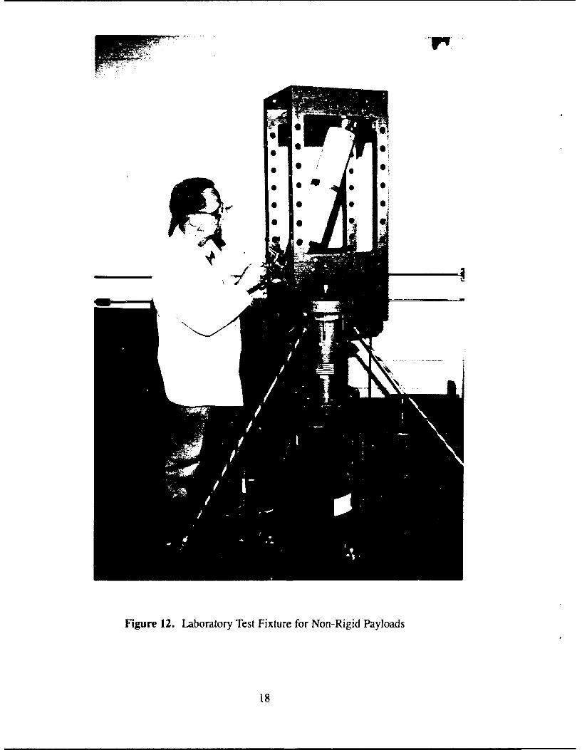
Figure 12. Laboratory Test Fixture for Non-Rigid Payloads
18

7. 155mm, SPINNING BARREL AIR GUN
The 155mm, Spinning Barrel Air Gun allows a variety of projectileconfigurations, weights and sizes to be launched over a large range of preselected velo-cities and spin rates. The gun barrel has an inside diameter of 155mm and an insidelength of 2.4 m. Propulsive energy is provided by gaseous nitrogen contained in a 0.1m3 rechargeable supply tank. The current maximum operating pressure for the gun is6.9 MPa which can be increased in the future to 20.7 MPa. A reusable, quick-openingvalve releases the high pressure nitrogen from the tank to the barrel in 3 milliseconds.Barrel spin is achieved by means of a nozzle/turbine arrangement using compressed air.
The gun and all ancillary components are mounted on a mobile trailer. Anotherspecial trailer contains standard compressed nitrogen bottles for recharging the gun.The gun and bottle trailers are shown in Figure 13. Compressed air for the barrel spinis acquired from a mobile, trailer mounted compressor. At a nominal pressure, the guncan launch a 4.5 kg projectile at 305 m/s. Heavier or lighter weight projectile can befired at correspondingly lower or higher velocities. Various projectile shapes and sizescan be fired by utilizing proper sabot designs. The barrel can be spun at spin rates from0 to 150 Hz independent of the desired launch velocity.
Ejection and dissemination of full scale payloads from 155mm artillery projec-tiles can be simulated with the gun producing the same velocity and spin rate conditionsexperienced in flight. The air gun will also allow the flight behavior of new chemicalmunitions to be evaluated without the instrumentation problems, complexity and costsassociated with the use of standard gun or rocket systems. Ballistic screens and dopplerradar instrumentation are available to measure muzzle and flight velocities. Details ofinflight performance of test projectiles can be obtained from high speed movies or stopaction still photographs.
19

/c
20

8. COMPUTER AIDED DESIGN SYSTEMThe branch includes a Computer Aided Design (CAD) system which allows
models, mounts and associated components to be designed and associated engineeringdrawings prepared. A typical workstation for the COMPUVISION CAD system isillustrated in Figure 14. Both planar, individual and assembly drawings as well aswire-frame and solid, three-dimensional formats can be created. These workstations aretied directly into the main CRDEC CAD computer network which uses identicalhardware and software elements. This makes possible the utilization of automatic com-puter aided equipment during fabrication in the CRDEC shop facilities which arelocated adjacent to the ARCA Br laboratory area. This arrangement permits the rapiddesign and fabrication of hardware required for experimental operations.
21

.0
E,
'C
milli=
22,