Chem. Listy - Chemické listy · Chem. Listy 101, s1 − s72 (2007) PMA 2007 & 19th SRC 2007...
14
Chem. Listy 101, s1 − s72 (2007) PMA 2007 & 19th SRC 2007 Contributed lectures 1 s19 CL-1-01 STUDY OF JUTE FIBRE-REINFORCED POLYESTER COMPOSITE MOHAMED ZOINAL ABEDIN* Department of Chemical Engineering and Polymer Sci- ence, Shah Jalal University of Science and Technology, Sylhet, Bangladesh [email protected] Chemically modified Jjte fibre (Hessian cloth) and e-glass fibre (mat)-reinforced unsaturated polyester (USP) resin composites were prepared using the hand lay up technique at room temperature (25 C). A strong inter- facial adhesion between jute and polyester was obtained using chemically modified jute fibre. This modification involves the introduction of reactive vinylic groups at the surface of the fibre and matrix through esterification of jute hydroxyl groups by methacrylic anhydride. Jute fibre content in the composite was optimized with the extent of mechanical properties and composites with 25 % jute show higher mechanical properties. The mechanical prop- erties are found to increase with the incorporation of dis- similar portions of glass fibre into the jute-reinforced com- posite. Among all the resulting hybrid composites, the composite with a jute to glass fibre ratio of (1:3) demon- strate the improved mechanical properties such as tensile strength (TS) 130 %, tensile modulus (TM) 50 %, bending strength (BS) 150 %, and bending modulus (BM) 225 % over untreated jute composite. Scanning electron micro- graphs of tensile fracture surfaces of unmodified and modified jute-polyester composites clearly demonstrate better fibre-matrix bonding in the case of the latter. CL-1-02 NEW GENERATION TECHNOLOGY FOR SURFACE FINISHING OF AUTOMOTIVE PLASTIC COMPONENTS WEIDONG YANG a , W. (VOYTEK) S. GUTOWSKI a *, SHENG LI a , MARK SPICER a , WILLIAM A. MATTHEWS b , and DAVID M. JAMES b a CSIRO Manufacturing & Materials Technology, Func- tional Interphases and Coatings, Graham Road (PO Box 56), Melbourne − Highett, Victoria 3190, b Dulux Austra- lia, Powdercoatings, 51 Winterton Road, Melbourne, Vic- toria 3168, Australia [email protected] Abstract Decorative finishing of injection-moulded automotive components requires the application of decorative surface finishes. Currently available alternative finish technologies include: solvent- or water-born wet paints, in-mould col- our achieved by pigments and dyes, or in-mould decora- tive films. Wet paints, most commonly used for decorative finishing of automotive plastic components exhibit very low transfer efficiency typically not exceeding 30−35 %. Consequently they constitute a major source of solid waste and emit VOCs, second only to the vehicles exhaust emis- sion. Powder coatings, an attractive 100 % solvent-free alternative technology, achieve 90−99 % transfer effi- ciency. However, they require electrostatic deposition of charged particles of powder coating. Hence, powder coat- ings are generally only used on inherently conductive me- tallic components, such as in the automotive, marine and construction industries, or on relatively costly conductive polymers. A rapid increase of powder-coating technology usage is also observed in the furniture industry. The key barriers to wide introduction of powder coat- ing technology in plastics surface finishing are: non- conductive plastic surfaces, inadequate adhesion to com- modity plastics such as polypropylene blends, and fre- quently − the absence of low-temperature curing powder coatings. This paper presents theoretical and practical as- pects of novel technologies facilitating successful powder coating of automotive and commodity plastics, eg: (i) pro- viding adequate surface conductivity of polymeric sub- strates, and (ii) coating adhesion. The principles of electrostatic powder-coating technology The principles of electrostatic powder-coating tech- nology are schematically illustrated in Fig. 1. The individ- ual powder particles charged by a corona discharge ioniser (see Fig. 1a) form a fluidised powder cloud in which all particles, bearing identical charge, repel each other. The oppositely charged conductive substrate (see Fig. 1a) at- tracts all particles which electrostatically self-assemble on its surface forming a semi-continuous particulate layer. At the next stage of the process the particulate-coated sub- strate is admitted to a curing oven in which three consecu- tive processes take place: (1) particles melting; (2) fluid self-levelling, and (3) cross-linking. Fig. 1. Basic principles of powder-coating technology: (a) electrostatic powder transfer; (b) electrostatic self-assembly of charged particles; (c) self-levelled coating layer a b c
Transcript of Chem. Listy - Chemické listy · Chem. Listy 101, s1 − s72 (2007) PMA 2007 & 19th SRC 2007...
Chem. Listy 101, s1 − s72 (2007) PMA 2007 & 19th SRC 2007 Contributed lectures 1
s19
CL-1-01 STUDY OF JUTE FIBRE-REINFORCED POLYESTER COMPOSITE MOHAMED ZOINAL ABEDIN* Department of Chemical Engineering and Polymer Sci-ence, Shah Jalal University of Science and Technology, Sylhet, Bangladesh [email protected]
Chemically modified Jjte fibre (Hessian cloth) and e-glass fibre (mat)-reinforced unsaturated polyester (USP) resin composites were prepared using the hand lay up technique at room temperature (25 °C). A strong inter-facial adhesion between jute and polyester was obtained using chemically modified jute fibre. This modification involves the introduction of reactive vinylic groups at the surface of the fibre and matrix through esterification of jute hydroxyl groups by methacrylic anhydride. Jute fibre content in the composite was optimized with the extent of mechanical properties and composites with 25 % jute show higher mechanical properties. The mechanical prop-erties are found to increase with the incorporation of dis-similar portions of glass fibre into the jute-reinforced com-posite. Among all the resulting hybrid composites, the composite with a jute to glass fibre ratio of (1:3) demon-strate the improved mechanical properties such as tensile strength (TS) 130 %, tensile modulus (TM) 50 %, bending strength (BS) 150 %, and bending modulus (BM) 225 % over untreated jute composite. Scanning electron micro-graphs of tensile fracture surfaces of unmodified and modified jute-polyester composites clearly demonstrate better fibre-matrix bonding in the case of the latter.
CL-1-02 NEW GENERATION TECHNOLOGY FOR SURFACE FINISHING OF AUTOMOTIVE PLASTIC COMPONENTS WEIDONG YANGa, W. (VOYTEK) S. GUTOWSKIa*, SHENG LIa, MARK SPICERa, WILLIAM A. MATTHEWSb, and DAVID M. JAMESb
a CSIRO Manufacturing & Materials Technology, Func-tional Interphases and Coatings, Graham Road (PO Box 56), Melbourne − Highett, Victoria 3190, b Dulux Austra-lia, Powdercoatings, 51 Winterton Road, Melbourne, Vic-toria 3168, Australia [email protected] A b s t r a c t
Decorative finishing of injection-moulded automotive
components requires the application of decorative surface finishes. Currently available alternative finish technologies
include: solvent- or water-born wet paints, in-mould col-our achieved by pigments and dyes, or in-mould decora-tive films. Wet paints, most commonly used for decorative finishing of automotive plastic components exhibit very low transfer efficiency typically not exceeding 30−35 %. Consequently they constitute a major source of solid waste and emit VOCs, second only to the vehicles exhaust emis-sion. Powder coatings, an attractive 100 % solvent-free alternative technology, achieve 90−99 % transfer effi-ciency. However, they require electrostatic deposition of charged particles of powder coating. Hence, powder coat-ings are generally only used on inherently conductive me-tallic components, such as in the automotive, marine and construction industries, or on relatively costly conductive polymers. A rapid increase of powder-coating technology usage is also observed in the furniture industry.
The key barriers to wide introduction of powder coat-ing technology in plastics surface finishing are: non-conductive plastic surfaces, inadequate adhesion to com-modity plastics such as polypropylene blends, and fre-quently − the absence of low-temperature curing powder coatings. This paper presents theoretical and practical as-pects of novel technologies facilitating successful powder coating of automotive and commodity plastics, eg: (i) pro-viding adequate surface conductivity of polymeric sub-strates, and (ii) coating adhesion. T h e p r i n c i p l e s o f e l e c t r o s t a t i c p o w d e r - c o a t i n g t e c h n o l o g y
The principles of electrostatic powder-coating tech-
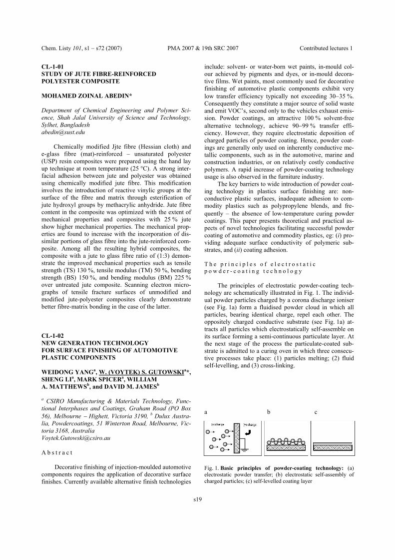
nology are schematically illustrated in Fig. 1. The individ-ual powder particles charged by a corona discharge ioniser (see Fig. 1a) form a fluidised powder cloud in which all particles, bearing identical charge, repel each other. The oppositely charged conductive substrate (see Fig. 1a) at-tracts all particles which electrostatically self-assemble on its surface forming a semi-continuous particulate layer. At the next stage of the process the particulate-coated sub-strate is admitted to a curing oven in which three consecu-tive processes take place: (1) particles melting; (2) fluid self-levelling, and (3) cross-linking.
Fig. 1. Basic principles of powder-coating technology: (a) electrostatic powder transfer; (b) electrostatic self-assembly of charged particles; (c) self-levelled coating layer
a b c

Chem. Listy 101, s1 − s72 (2007) PMA 2007 & 19th SRC 2007 Contributed lectures 1
s20
S u r f a c e - c o n d u c t i v e a n d a d h e s i o n e n h a n c i n g p o l y m e r i n t e r p h a s e s
The lack of bulk and surface conductivity of polymers
can be, to a limited extent, overcome by the use of either, conductive polymer blends containing adequate levels of conductive fillers, or by the use of conductive primers applied prior to powder coating deposition. These can be alternatively achieved by the addition of conductive car-bon black (10−16 %), carbon nano-tubes (2−5 %), or other additives. The above solutions are, however, not sustain-able due to the high material cost, and high volatiles con-tent in commodity conductive primers.
A plausible solution of the above problems can be achieved by surface engineering of polymers with the use of specialty multi-functional molecules. Once grafted onto the surface of a commodity polymer, eg. polypropylene, nylon or other automotive plastic, they provide the follow-ing properties of the interphase without adversely affecting the bulk properties of the underlying substrate material: − electro-conductivity, and − adhesion promotion of the powder-coating polymer.
Figure 2 provides a schematic illustration of the prin-ciples underlying the design of such multi-functional inter-phase. A nano-layer of conductive molecules (item [2] in Fig. 2) is chemically grafted onto the surface of a non-conductive polymer at the concentration facilitating uni-form charge transfer between adjacent molecular clusters. This, in turn, leads to electro-deposition of an even layer of powder coating particles across the whole surface of the polymeric substrate. The untreated polymers typically exhibit surface resistivity in the order of 1014 Ω/square, which completely impedes electrostatic deposition of charged particles. To achieve uniform transfer of powder coating particles, and facilitate formation of a smooth coat-ing layer after melt-flow and self-levelling of molten parti-cles, the resistivity of polymer surface must fall below the threshold value of approximately 10−11 Ω/square. Data in
Fig. 3 demonstrate significantly improved surface con-ductivity (i.e. reduced resistivity) of Nylon 6-6 after sur-face grafting two alternative types of conductive adhesion promoter molecules:A and B.
Photos in Fig. 4 illustrate, in turn, the effectiveness of electrostatic transfer and deposition of powder coating particles onto the surface of PP substrate whose surface has been modified with electro-conductive adhesion pro-moter molecules A providing surface resistivity of approx. 2⋅10−10 Ω/square. An excellent quality of progres-sive powder coating deposition over the whole substrate surface is clearly demonstrated through this sequence of photos.
During the subsequent heating and melting of parti-cles and ensuing film forming, the surface-grafted conduc-tive molecules uncoil, as schematically illustrated in Fig. 2b, and interpenetrate the polymeric coating layer, hence enhancing the coatings adhesion to the surface of the coated product. REFERENCES 1. Bauch H.: Besser Lackieren, No 7&8 (2005). 2. Little M.: Products Finishing Magazine, Jan (2005). 3. Powder coated MDF kitchen elements in Belgium,
FacharticelLedro-2N, Aug 2004.
Fig. 4. The effectiveness of powder coating particles transfer onto the surface of PP-based substrate surface-modified by electro-conductive molecules A
Fig. 3. Surface resistivity of Nylon 6-6: (a) untreated; (b) con-ductive adhesion promoter molecules A; (c) conductive adhesion promoter molecules B
Fig. 2. Schematics of design principles of multi-functional polymer interphase for surface electro-conductivity and adhe-sion enhancement: (a) electro-conductive interphase with elec-tro-statically self-assembled particles of powder coating: [1] powder coating particles;[2] nano-layer of conductive adhesion promoter; (b) unfolded molecules interpenetrating into a layer of powder coating particles
a b

Chem. Listy 101, s1 − s72 (2007) PMA 2007 & 19th SRC 2007 Contributed lectures 1
s21
CL-1-03 ANALYSES OF INHOMOGENETIES OCCURRING IN THE INJECTION PROCESS PETR HALAKAa* and ZDENEK DVOŘÁKb a Smartplast, Svatopluka Čecha 513, 760 01 Zlín, b Tomas Bata University in Zlin, Nad Stráněmi 4511, 762 72 Zlín, Czech Republic [email protected], [email protected]
Injected plastic parts are used mainly in consumer and automotive industry, in electrotechnics, electronics and in packaging. For all these industries there is typical very fast moral product obsolescence caused by dynamics of market development and competitive environment as well as fash-ion and demanding consumers. Situation in a continuously changing market needs fast development and construction of injected products and tools necessary for their produc-tion.
Moreover, in the global market the teams who solve part design, tool design and production technology can be thousands of kilometers and several time zones from one another. If such teams do not have precise values describ-ing design, tool and technology, their communication can be very complicated or conflicting and mainly it leads to increase of costs and longer time for launching a new product in the market. Mainly the second aspect can lead to big financial loss from the time when we are not the first and only in the market who offer a new product.
Analytic SW Moldflow with is complex solving of the whole injecting process offers a global service that is always a step ahead of your plans. That means that design-ing teams can get perfect instruments for communication in global world and precise values describing both the injected part and the tool and technical parameters.
The analytic SW Moldflow works on the basis of final elements method. The final element method is a mod-ern, highly efficient numeric method for solving technical and scientific tasks. Nowadays it is considered one of the most effective approximate solving methods.
Inhomogeneties in the injection process occur mainly due to inhomogeneous pressure and temperature field. Different temperatures in section and length of flow path lead to unbalanced changes of volume during cooling of the polymer melt and during polymer transition from visco-plastic state to the solid stage. Occurrence of inho-mogeneities is affected by injection speed, packing and cooling speed. Just thanks to the Moldflow volume analy-sis we are able to describe these stages very well.
We described temperature field of a sample of an injected board 100×100 mm, 3 mm thick, injected in speed of 60, 100 and 140 mm s−1. We took samples at four dif-ferent distances from the gate. We can also compare mor-phologic structure of the sample in microtone cuts with temperature field in the cavity analyzed by Moldflow vol-ume analysis. Inhomogeneous temperature and pressure field affects not only morphologic structure but also me-chanic properties as we can see on the dependence of ten-sile module and direction of drawing force and injection speed. Also changes in morphologic structure show differ-ent values of the tensile module in the section of the prod-uct. In this case the module was measured by nanoindenta-tion, i.e. indenting a triangular prism into the sample. The tensile module is calculated from the course of indentation.
REFERENCES 1. Halaka P., Maňas M.: Residual Stress within Injec-
tion Process. In: Annals of DAAAM for 2005 & Pro-ceedings, 16th International DAAAM Symposium Sci-entific Conference. DAAAM International Viena, 2005. p.151−152.
2. Halaka P., Maňas M.: Plastic Part Development Us-ing Advanced Technologies and Tools. In: TMT 2006 Proceedings, 10th International Conference TMT2006, Barcelona, 2006, p. 413−416.
Fig. 2. Temperature field in the section of the injected sample part
Fig. 1. Injected sample part

Chem. Listy 101, s1 − s72 (2007) PMA 2007 & 19th SRC 2007 Contributed lectures 1
s22
CL-1-04 EFFECT OF NANOCLAYS ON THE FLAME RETARDANCY OF POLYMER NANO-COMPOSITES VIERA KHUNOVAa*, IVAN KELNARb, PETER SIMONa MARTIN DUCHONc, IVANA TUREKOVÁc, and KAROL BALOGc a The Slovak University of Technology, Faculty of Chemi-cal and Food Technology, Institute of Polymer Materials, Radlinského 9, Bratislava, Slovakia, b Institute of Macro-molecular Chemistry, Academy of Sciences of the Czech Republic, Heyrovsky Sq. 2, 162 06 Prague, Czech Repub-lic, c The Slovak University of Technology, Faculty of Ma-terial Science and Technology, Institute of Safety a Environmental Engineering, Botanická 49, Trnava, Slo-vakia [email protected]
Highly flammable polymers, such as polyolefins, can be produced flame retardant either by organo-halogens or metal (Mg, Al) hydroxides. Application of halogen based flame retardants, however, is accompanied by an evolution of thick smoke and highly acidic hydrogen halide gases. Large amounts (60 % w/w) of Mg and Al hydroxide re-quired to attain acceptable flame retardancy has a negative impact on the end-use properties of polymers1.
Unlike traditional flame retardants, flame retardancy of polymer nanocomposites is based on the char formation and its structure2. The char insulates the polymer from heat and forms a barrier reducing the escape of volatile gases from the polymer combustion3. Moreover, the filler con-tent in nanocomposites usually do not exceed 5 % w/w2. Reduction of flammability together with high strengths and potential recyclability are thus the main attributes in increasing the application of polymer nanocomposites in automotive industry.
In this paper the effect of nanoclays on flame retar-dancy of polymer nanocomposites is investigated. In order to unravel the influence of filler and polymer matrix struc-ture, composites based on organoclays (Cloisite 30B, Nanocor I-3TC, Nanoblend 1001) and polymer matrix (polypropylene, polyamide, polyethyleneterephtalate and polystyrene) have been investigated. The composites were prepared by melt blending in a twin-screw extruder and/or in a mixing chamber. The filler content was kept constant at 5 % w/w. The flammability behavior was investigated by the determination of limited oxygen index (LOI), igni-tion point (IP) and inflammability point (IFP). In addition to the above regulatory flame testing methods, thermogra-vimetric analysis has been also examined. The data ac-quired from TGA include the oxygen onset temperature (OOT), peak maximum temperature (PMT) and solid resi-due at 500 °C.
DTA curves and flammability measurements for PP/clay composites (Fig. 1, Table I) indicate a considerable increase in the oxygen onset temperature and 30 °C en-
hancement of the ignition point. By the application of reactive modifier, further improvement of OOT and IP have been observed, however, only a small effect on the value of limited oxygen index (Fig. 2) was observed.
Further examination of the combustion process under fire conditions revealed a considerable different flame mechanism in both, unmodified and modified PP/clay nanocomposites in comparison to neat PP.
Whilst during burning of PP, typical polymer flow accompanied by melt dripping is evident (Fig. 2a), PP/clay composites (Fig. 2b,c) did not indicate any flow or melt dripping.
Table I Flammability data for PP/clay nanocomposites
Sample IP [°C] OOT [°C] PMT [°C] Neat PP 350 210 310 PP/ clay 380 305 380
Modified PP/ clay − 335 405
__ __ PP __ PP/clay
__ PP __ PP/clay
Fig. 1. DTA curves for neat PP and PP/clay nanocomposites
Limiting oxygen index
19
19,5
20
17
18
19
20
Neat PP PP + 5 % w/w Nanoblend 1001
PP + 5 % w/w Nanoblend1001 + 5 % w/w DBMI
Fig. 2. LOI of PP/clay nanocomposites

Chem. Listy 101, s1 − s72 (2007) PMA 2007 & 19th SRC 2007 Contributed lectures 1
s23
In our recent work it was found that the application of reactive modifiers in PP/organoclay nanocomposites re-sulted in an extensive exfoliation of silicate platelets and a better filler dispersion4. Observation of the combustion process from its beginning from the inflammation point (Fig. 3a) followed by burning (Fig. 3b) up to the termina-tion of flaming (Fig. 3c) highlight the mutual effect of the nanoclay and modifier on the flame retardancy mechanism of PP/clay nanocoposites. Unlike unmodified composites (Fig. 2b), the samples kept their original size and shape and no deformation was observed during the burning proc-ess.
From Tables II and III is evident that the most signifi-cant effect of nanoclays on flame retardancy was observed in PET nanocomposites.
In the presentation, further insight of the effect of nanoclay structure and modification of nanocomposites on the flame retardancy and combustion process will be pre-sented.
Acknowledgement. The financial support from the Slovak Scientific Grant Agency (VEGA) grants No. 1/2110/05 and No. 1/3567/06, is gratefully acknowledged. REFERENCES 1. Liauw C. M., Khunová V., Lees G. C., Rothon R. N.:
Macromol. Symp. 194, 191 (2003). 2. Beyer G.: Plastics Additives & Compounding October
22−28, (2002). 3. Morgan A. B.: Polym. Adv. Technol. 17, 206 (2000). 4. Khunová V., Kelnar I., Klimová D., Lehocký P.: Po-
ceedings of conference Nanostructured and Func-tional Polymer-based Materials and Nanocompo-sites (NANOFUN-POLY), Lyon, 2006.
CL-1-05 HYBRIDE COMPOSITES OF PE WITH BIRCH FIBERS AND NANOCLAY BOHUSLAV V. KOKTAa*, LAW KWEI-NAMa, IVAN FORTELNYb, FRANTISEK LEDNICKYb, and ZDENEK KRULISb a Université du Québec à Trois-Rivières,Trois-Rivières, PQ, Canada,G9A5H7, b IMCH, Heyrovsky Square 2,Prague, Czech Republic [email protected]
Maximization of Impact strength, Tensile, Modulus
of natural fibre and nanoclay filled polyethylene was stud-ied by applying Central composite design (CCD): 23 + star design which studies the 3 experimental factors (NC, MAPE,DCP) in 16 tests. The order of the experiments was randomized. M a t e r i a l s u s e d w e r e a s f o l l o w s Thermoplastics: Linear low density polyethylene was sup-plied by Novacor chemicals Ltd (NPE, granular). Fibres: As a wood fiber we used birch fibre (20−60 mesh) which was prepared in laboratory. Coupling agents: Maleated polyethylene (MAPE) was supplied by Eastman chemical company as a coupling agent. Initiator: Dicumyl peroxide (DCP) 98% purity, supplied by Sigma. It has a melting point of 39−41 °C and it will decompose rapidly above 120−125 °C. Filler: Cloisite Na+ Nanoclay (NC) was used as a filler.
Sample LOI [%O2] IP [°C] OOT [°C] Neat PS 19.0 430 290 PS/ clay 19,5 460 365
Table III Flammability data for PS/clay nanocomposites
Table II Flammability data for PET/clay nanocomposites
Sample LOI [%O2] IP [°C] OOT [°C] Neat PET 24,5 322 320 PET/ clay 28,0 354 390
Fig. 2. Combustion of neat PP (a) and PP/clay composite (b)
a b
Fig. 3. Combustion process of modified PP/clay composites

Chem. Listy 101, s1 − s72 (2007) PMA 2007 & 19th SRC 2007 Contributed lectures 1
s24
C o m p o u n d i n g
A 30 wt.% PE with MAPE and Cloisite Na+ Nano-clay was melted on rollers at 170 °C at 60 rpm. Then birch fibres were added to the mix followed by the addition of the remaining PE, within 7 min. The mixture was removed from the rollers five times with 3 min mixing times. Fi-nally the DCP was added and mixed for 3 min. The com-posite was then removed from the roller and cut into strips large enough to fill the moulds. C o m p r e s s i o n m o u l d i n g
The strips were pressed into the dog bone shaped moulds (ASTM D638 Type V). Twenty-two specimens (10 for tensile testing «thick» and 12 for impact strength testing «thin») were simultaneously prepared in the same mould. The mould was maintained at 170 °C, in a DAKE PRESS. The pressure was increased to 20 MPa and held for 15 min. After the high pressure stage, the press was cooled below 60 °C by circulating cold water in the plat-ens. The dimensions of the tensile specimens were as follows: width, 0.29−0.32 cm, and thickness, 0.29−0.32 cm. Width of impact test specimens was 0.27−0.29 cm and the thick-ness was 0.16−0.19 cm. M e c h a n i c a l t e s t s
All the specimens were polished, then equilibrated in testing room overnight, and then the width and the thick-ness was measured with a micrometer.
Tensile testing was performed on an Instron Model 4201 at 23 °C and 50 % relative humidity, and all the bro-ken specimens were kept for further study. Such analysis included SEM, FT-IR, TGA etc. Impact strength was de-termined by a Wick tester at ambient temperature (about 23 °C). S u m m a r y
Maximization of Impact strength, Tensile, Modulus of natural fibre and nanoclay filled polyethylene as achieved by applying Central composite design is pre-sented in the following figures.
In summary the Strength and Impact values of com-posites increased simultaneously when compare to pure PE as follows: Impact strength increased from 115 kJ m−2 to 171 kJ m−2 , Stress from 25 MPa to 49 MPa and Modulus from 555 MPa to 926 MPa. Composites samples were examined directly by ESM and explanation of presented behavior is advanced. Acknowledgements. The authors would like to thank to Network of Centres of Excellence, AUTO 21 (The Automo-bile of the 21st Century) and the NSERC for the financial support.
115.0593.3
106.511
171.219
0
50
100
150
200
Polyeth
ylen e
Compo si te
10%
Compo si te
20%
Compo si te
30%
Impact, kJ/m2
25.05 26.41
32.6540.6717
0
10
20
30
40
50
Polye th
ylen e
Compo si te
10%
Compo si te
20%
Compo si te
30%
Stress, MPa
555.6698.29
811.94926.181
0
200
400
600
800
1000
Polyeth
ylen e
Compo
site 1
0%
Compo
site 2
0%
Compo
site 3
0%
Modulus, MPa
1000
850
1450
941
0
200
400
600
800
1000
1200
1400
1600
Pric
e (C
AD
/ton)
PE 70% PE30% Birch Fibres
70% PE30% Glass Fibres
67.4% PE30% Birch Fibres
1% NC0.1% DCP
1.5% MAPE

Chem. Listy 101, s1 − s72 (2007) PMA 2007 & 19th SRC 2007 Contributed lectures 1
s25
REFERENCES 1. Eckert C., in: Proceedings Progress in Woodfibre-
Plastic Composites conference, Toronto, Ontario, Canada, May 25−26, 2000.
2. KarayanV., Neuber F., Dodds D., in: Proceedings 7th Toronto Conference on Progress in Wood Fiber − Plastic Composites, Toronto, Canada, May 23−24, 2002.
3. Plackett D., in: Proceedings Progress in Woodfibre-Plastic Composites conference, Toronto, Ontario, Canada, May 23−26, 2002.
4. Peijs T.: E-Polymers, no. T _002. (2002). 5. Park H.-M., Lee W.-K., Park C.-Y., Cho W.-J., Ha C.-
S.. J. Mat. Sci. 38, 909 (2003). 6. Pramanik M., Srivastava S. K., Samantaray B. K.,
Bhowmick A. K.: J. Polym. Sci., Part B: Polym. Phys. 40, 2065 (2002).
7. Pinnavaia T. J., Beall G. W., in: Polymer-Clay Nanocomposites. Wiley, New York 2000.
8. Novak B. M.: Adv. Mater 5, 422 (1993). 9. Messersmith P. B., Stupp S. I.: J. Mater. Res. 7,
2599 (1992). 10. Okada A., Usuki A.: Mat. Sci. Eng., C 3, 109
(1995). 11. Li J.-X., Wu J., Chan C.-M.: Polymer 41, 6935
(2000). 12. Sherman L. M.: Plastics Technology − New York 45,
52 (1999). 13. Becker C., Kutsch B., Krug H., Kaddami H.: J. Sol-
Gel Sci. Techn. 13, 499 (1998). CL-1-06 COMPUTATIONAL SIMULATION OF COMPOSITES REINFORCED BY SHORT FIBERS VLADIMÍR KOMPI* and MÁRIO TIAVNICKÝ Academy of Armed Forces, 031 19 Liptovský Mikulá, Slovakia [email protected].
Composite materials reinforced with stiff micro/nano fibers are becoming important structural materials. Large differences in the stiffness of the matrix and fibers, large number of the fibers and large aspect ratio make the accu-rate analysis of such structures very cumbersome. The bearing capacity of such materials, stiffness evaluation and material design require correct analysis of the material behavior up to the micro- or nano-scale. Large gradients in displacement, strain and stress fields are responsible for low efficiency of computational methods like classical FEM and BEM. Billions of equations would be necessary to simulate accurately enough the interactions fiber with matrix, fiber with other fibers and other effects with these methods. We developed a new method, called the Method of Continuous Source Functions (MCSF) using both dis-crete and continuous source functions inside fibers to
simulate the compatibility conditions between the fiber and matrix. It enables considerably reduce the problem.
Only straight and regularly distributed fibers are con-sidered in the present models. Both ideal cohesion and de- and re-cohesion effects are possible to model.
The ordered fibers enable to obtain a material, which can have very attractive mechanical properties. It can be much stiffer and stronger in one direction than in other directions. The direction can be locally changed according to the loading conditions. There are some technologies like casting which enable to control the processing of the com-posite.
From the mechanical point of view, both near and far field are important to be accurately simulated. The near fields are responsible for the bearing capacity of the com-posite and the far fields are responsible for stiffening ef-fect.
As the source functions are similar also for other physical fields like thermal conductivity, or electro-magneto- mechanical fields, the method used in the pre-sent simulation can be used also for modeling of such problems, although the singularities can be different for different fields, but the mechanical fields contain all, weak, strong and hyper-singularities and so, they can serve to be basis for numerical studies of their behaviour in dif-ferent conditions. However, many studies have to be done to develop the method to manage complex behaviour like nonlinear physical and geometrical effects. Acknowledgement. Partial support of this research by the Slovak Agency for the Support of R&D grant APVT-20-035404 and by NATO grant 001-AVT-SVK is acknowl-edged. CL-1-07 SHAPE STABILIZED PHASE CHANGE MATERIALS BASED ON THE POLYETHYLENE AND PARAFFIN WAXES IGOR KRUPAa*, GIZELA MIKOVÁa, and RIAAN LUYTb
a Polymer Institute, Slovak Academy of Sciences, Dúbravská cesta 9, 842 36 Bratislava, Slovakia, b Department of Chemistry, University of the Free State (Qwaqwa Cam-pus), Private Bag X13, Phuthaditjhaba, 9866, South Africa [email protected]
Phase change materials (PCM) are substances with a high heat of fusion which, through melting and solidify-ing at certain temperatures, are capable of storing or re-leasing large amounts of energy1. PCM have received great interest in many applications such as energy storage and thermal protection systems as well as in active and passive cooling of electronic devices2.
PCM, based on low density polyethylene blended with soft paraffin wax and hard Fischer-Tropsch paraffin

Chem. Listy 101, s1 − s72 (2007) PMA 2007 & 19th SRC 2007 Contributed lectures 1
s26
wax respectively, were studied in this work. Differential scanning calorimetry, dynamical mechanical analysis, thermogravimetric analysis and scanning electron micros-copy were employed to determine the structure and prop-erties of the blends. The blends were able to absorb large amounts of heat energy due to melting of paraffin wax, whereas the LDPE matrix kept the material in a compact shape on macroscopic level. Different behavior was ob-served for the two paraffin waxes. The Fischer-Tropsch paraffin wax was much more miscible with LDPE (Fig. 1) in comparison to the soft paraffin wax (Fig. 2). LDPE blended with Fischer-Tropsch wax degrades in just one step, while blends containing soft paraffin wax degrade in two distinguishable steps. SEM showed completely differ-ent morphology for the two paraffin waxes and confirmed the lower miscibility of LDPE and soft paraffin wax. DMA analyses clearly demonstrated the toughening effect
of the waxes on the polymeric matrix. This technique was also used to follow the thermal expansion as well as the dimensional stability of the samples during thermal cy-cling. Controlled force ramp testing on DMA confirmed poor material strength of the blends containing soft wax, especially at temperatures above wax melting. The highest concentrations at which the polymeric material was able to sustain the external forces as well as the thermal cycling were at 40 wt.% soft and 50 wt.% Fischer-Tropsch wax. Acknowledgements. The research was supported by the National Research Foundation in South Africa (GUN 2070099), the University of the Free State, and the Scien-tific Grant Agency of the Ministry of Education of Slovak Republic and the Slovak Academy of Sciences (project No. 2/6114/26). REFERENCES 1. Abhat A.: Solar Energy 30, 313 (1983). 2. Zalba B., Marin J. M., Cabeza L. F., Mehling H.:
Appl. Therm Eng. 23, 251 (2003). CL-1-08 SEARCH FOR THE STABILISATION MIXTURE WITH THE MAXIMUM STABILIZING EFFECT USING THE SIMPLEX METHOD MARTA MALÍKOVÁ*, PETER IMON, and HEINZ-WILHELM WILDE FCHPT STU, Radlinského 9, 812 37 Bratislava, Slovakia [email protected]
The simplex method for the function minimization has been applied for finding the optimal composition of a stabilizing mixture for polyurethane coatings. Regarding the degradation of polyurethane coatings for automotive interior applications, the crucial factors are temperature and UV radiation1. The stabilizer mixture consisted of HALS, UV absorber and an antioxidant. The residual sta-bility of the samples after accelerated ageing was assessed by the measurement of oxidation onset temperatures using the differential scanning calorimetry (DSC).
The stabilizing effect often exhibits the maximum for a particular composition of the stabilizer mixture. For the development of new coating formulations, the design of experiment or the trial-and-error methods are used. Both methods are quite labour- and time-consuming. It would be advisable to find the maximum more straightforwardly by using a non-gradient optimization method. In order to find the optimal composition of the mixture, the simplex method for function minimization is employed2.
The minimization of a function of n variables is based on the comparison of function values at the (n+1) vertices of a general simplex, followed by the replacement of the vertex with the highest value by another point. The sim-plex adapts itself to the local landscape and contracts on to
Fig. 1. SEM micrograph of LDPE/Fischer-Tropsch paraffin wax blends
Fig. 2. SEM micrograph of LDPE/soft paraffin wax blends

Chem. Listy 101, s1 − s72 (2007) PMA 2007 & 19th SRC 2007 Contributed lectures 1
s27
the final minimum (Fig. 1). It has been shown that the procedure provides readily
the stabilizer composition with the maximum protection effect.
REFERENCES 1. Yang X. F., Tallman D. E., Bierwagen G. P.: Polym.
Deg. Stab. 77, 103 (2002). 2. Nelder J. A., Mead R. A.: Computer J. 7, 308 (1965). CL-1-09 IRRADIATION OF POLYMERS MATERIAL DAVID MANAS, MIROSLAV MANAS*, MICHAL STANEK, and TOMAS DRGA Department of Production Engineering, Faculty of Tech-nology, Tomas Bata University, TGM 275, 762 72 Zlin, Czech Republic [email protected]
Radiation processing involves the use of natural or man made sources of high energy radiation on an indus-trial scale. The basic of radiation processing is the ability of the high energy radiation to produce reactive cations, anions, and free.
Radiations processing involves mainly the use of either electron beams from electron accelerators or gamma radiation from Cobalt 60 sources. Radiation processing does not make product radioactive.
A major of industrial applications of radiation proc-essing are cross-linking of wire and cable insulations, tube, heat shrink cables, components of tires, composites, mould product, for automotive and electrical industry etc.
A second major application of radiation processing is sterilization of medical disposables.
The cross-linking of rubbers and thermoplastic poly-mers is a well proven process the improvement of the thermal properties.
The irradiation cross-linking of thermoplastic mate-rials via electron beam or cobalt 60 (gamma rays) takes place separately after the processing. The level of cross- linking can be adjusted with the irradiation dosage and in many cases with the help of a cross-linking booster.
The main deference between beta and gamma rays lies in their differing abilities to penetrate the irradiated material. Gamma rays have a high penetration capacity. In the case of electron rays, penetration capacity depends on the energy of the accelerated electrons.
With electron accelerators, the required dose can be applied within seconds, whereas several hours are re-quired in the gamma radiation plant.any case. References should be indented to tab 7 mm and format to block, use Times 9 pt again.
Properties of natural (not irradiated) and irradiated polypropylene (PP) both unfilled and filled with 25% of glass fibres have been compared.
Used polymers: − PTS Crealen EP 2300L1 M800 (unfilled PP),
− PTS Crealen EP8G5HS* M0083 (PP filled 25% glass fibres).
0.0 0.2 0.4 0.6 0.8 1.0 1.2 1.4 1.6 1.8
0.0
0.2
0.4
0.6
0.8
1.0
d
_P
b
ac
1st iterationUV
A [p
hr]
HALS [phr]
Fig. 1. First iteration of the optimization procedure
Fig. 1. Design of Gamma rays (a) and Electron rays (b); (a) 3 secondary electrons, 4 irradiated material, 5 encapsu-lated Co 60 radiation source, 6 Gamma rays, (b) 1 pene-tration depth of electron, 2 primary electron, 3 secondary electron, 4 irradiated material
Fig. 2. Results of thermal stability
a b

Chem. Listy 101, s1 − s72 (2007) PMA 2007 & 19th SRC 2007 Contributed lectures 1
s28
Irradiation was realized in the work of the firm BGS Beta Gamma Service GmbH & Co, KG, Saal am Donau, Germany with the electron rays, electron energy 10 MeV, doses minimum of 15 and 33 kGy.
The most important results have been found by TMA analyses3. The irradiation has enormous influence on the thermal stability of both filled and unfilled PP, as it is possible to see from (Fig. 2).
The big differences of mechanical and thermal prop-erties of irradiated and natural PP was found. From the point of view of practise use the most important is the enormous improvement of thermal stability of irradiated PP. In next works, the further polymers will be tested. Acknowledgement. This article is financially supported by the Czech Ministry of Education, Youth and Sports in the R&D project under the title Modelling and Control of Processing Procedures of Natural and Synthetic Poly-mers, No. MSM 7088352102. REFERENCES 1. Singh A., Silverman J.: Radiation Processing of Poly-
mers. Oxford University Press, New York. 2. Basell Polyolefins Company N. V.: Technical manual,
2005. 3. Válek M., Manas D., Staněk M., Daněk M.: Vliv
ozařování na vlastnosti plastů. In: ITC 2006, 56. září 2006, UTB ve Zlíně, ISBN 80 7318 448 65.
CL-1-10 ARE THE FILLED POLYOLEFINE A PROMISSING MATERIAL? EVA NEZBEDOVÁ* Polymer Institute Tkalcovská 36/2, 656 49 Brno, Czech Republic [email protected]
The use of commodity polymers in many technical applications is limited due to its material behaviour − ther-mal stability, barrier properties, toughness or mechanical strength. That is the reason why to modify the basic poly-mer with fillers, reinforcement at different macroscale, microscale as well as nanoscale level. All the physical and chemical properties can be modified by way of fillers. Now a day there is not an exact limit between the fillers and additives. The real compounds are considered rather for composites in that the polymer serves as binding mean for fillers, pigments and processing agents.
The fillers are added in a great amount to PVC, PP, PE, and PA. Approximately 47 % of PVC-U are used for manufacture of pipes (26.5 %) and profiles (20.5 %). The content of fillers in these products is up to 15 % that repre-sent the most import field as the volume of fillers con-cerns. Exclusive filler is CaCO3. From the ecological view are the pipes and profile produced from PP, PE, PP foams,
(PE+PS) blends, PS and polymers filled with wood. Nev-ertheless there is a big economical and technological prob-lem that explains the growth of PVC profiles in future about the 3 %. The main customer of reinforced and filled PP is the automobile industry. PE filled with CaCO3 is used as sheets in agriculture and antiblock application. Semi-permeable sheets became the reality due to adding the very find grinned, surface coating CaCO3 with narrow distribution. The main branch of its application is sanitary sphere. Fillers are in the form of masterbatches, content of 5 % is sufficient for most application. Among the engi-neering polymers only PA is modified with filler (calcining kaolin, mica, talc and wollastonite). The secular trend heads toward to minimum content of fillers and im-provement of its mechanical properties. This aim can be achieve only in the way of using the selective fillers with high aspect ration or to use very fine particles or both1. The technologies of grinding were used for this purpose.
Nanofillers represent the particles with the size less than few nm (black, silica, whiskers and various pigments of TiO2). Nevertheless in many cases the particles have a trend to agglomerate and built up particles with size of several µ. This problem starts to be solved some years ago1,2 and is based on mechanisms of exfoliation of lay-ered silicates during melt processing. In this way it is pos-sible to prepare composites with aspect ration up to 1000. Content of such particles can be up to 80 %. The optical properties of these composites are not influenced since the particles are shorter than the wavelength of the light.
Utilization of organic fillers first of all woodfibers and sawdust particles in thermoplastics represent an attrac-tive composite3. The reason is its availability, favourable ration between price and volume and further specific prop-erties (low hardness, that minimize the wearing of process-ing devices, relative low density with comparison to com-posite with inorganic fillers, biodegradation). The problem is to achieve the necessary dispersion and strong interface, while the reinforcement is hydrophilic and matrix hydro-phobic. The various surface coating of fillers (anhidride, silane, MAPA) and nucleation agents (benzoate sodium) are use to remove this disadvantage. The further problem is the great dependence on rheological properties during processing.
The system PP matrix filled with rigid submicro-scopic particles was chosen to illustrate the way how to enhance the toughness of this system by keeping its stiff-ness4−7. The first step is to modify relevant parameters of the matrix at molecular as well as super molecular level (adding α and β nucleation agent). Effect of particles on the properties and behavior of system strongly depends on its size, shape, surface coating and distribution. Mecha-nisms of toughening (creation of shear bands) can starts after releasing the stress concentration on the interface. It can be realized under following conditions: − size of particles < 5µm, formation of free volume, − aspect ration narrow to 1, prevent the creation of high
stress concentration,

Chem. Listy 101, s1 − s72 (2007) PMA 2007 & 19th SRC 2007 Contributed lectures 1
s29
− homogeneously distributed particles, prevent the crea-tion of agglomerates,
− debonding at the particles-polymer interface has to be achieve before the yield stress of the matrix6, other-wise no change in the stress state of the matrix takes place.
Acknowledgement, the work was financially supported by grand No. 106/07/1284 of the GACR. REFERENCES 1. Hohenberger W.: KU Kunststoffe plast europe 90, 36
(2000). 2. Raab M.: Plasty a kaučuk 36, 132 (1999). 3. Son J., Gardner D. J., ONeil S., Metaxas C.: J. Appl.
Polym. Sci. 89, 1638 (2003). 4. Kim G. M., Michler G. H.: Polymer 39, 5699 (1998). 5. Moczo J., Fekete E., Laszlo K., Pukanszky B.: Macro-
mol. Symposia 194, 111 (2003). 6. Zhang L.: J. Polym. Sci., Part B: Polym. Phys. 42,
1656 (2004). 7. Jančář J., Pavelka V., Nezbedová E., ídek J.: Chem.
Listy S 99, 10 (2005). CL-1-11 MODELING AND SIMULATION OF THE IMPACT BEHAVIOR OF FOAMS M. REITERa, Z. MAJORb,c,2*, CH. KNOTZa
, and R. W. LANGb,c a CW Concept Consulting GmbH, Gratkorn, b Institute of Materials Science and Testing of Plastics, University of Leoben, Leoben, c Polymer Competence Center Leoben GmbH, Leoben, Austria [email protected]
Due to there energy absorbing and dissipating capa-bilities, polymeric foams are frequently used in the auto-motive industry. They are intended to be used at relatively low stress levels, what makes them predestined for occu-pant and pedestrian protection. For an effective engineer-ing and development of a new vehicle you have to be able to predict the material behaviour in crash situations. This keeps you from doing unnecessary crash-test and raising the development costs. These complex crash situations are mainly simulated with FE-programs, which are based on material models and parameter that describe the crash be-haviour of the materials. The objective of this work is the development of a novel methodology for characterising the impact behaviour of polymeric foams.
At the beginning the foams were tested with a com-monly used method to be able to compare with the new achieved impact data. For this purpose the foams were tested under a monotonic uniaxial compression load using testing machines, where the dependency of force and dis-placement was measured and transposed to stress-strain
data. The new method is based on an impact test with a free motion steel plate that hits the specimen, which is mounted on the floor. To comply with the assumption of a uniaxial load case, the specimen has to have a cubical or cylindrical shape.
These tests differ from the monotonic compression tests on one hand in the loading rate and on the other in the kind of measurement. The measurement only consists of an acceleration sensor on the impacting body.
With the assumption of an uniaxial impact load and a zero Poisons ratio one can calculate the function of stress, strain and strain rate as well as the hysteretic behav-iour of the foam. The quality of this data can be instantly checked by simulating these tests with the same calculated material parameters und comparing the simulation results with the real tests.
To show that these material parameters achieved from uniaxial impact tests are also applicable to more complex load situations, test with a spherical impact body were
Fig. 1. The acceleration curve measured during the impact test and the calculated velocity profile for EPP foam
Fig. 2. The stress-compression-strain rate diagrams of an EPP foam at loading rate of 8 m s−1

Chem. Listy 101, s1 − s72 (2007) PMA 2007 & 19th SRC 2007 Contributed lectures 1
s30
made and compared to the simulation results. Here we have a method to characterise the behaviour of polymeric foams under an impact load. The advantage is that this is a cost and time efficient method to achieve foam data, that correspond to the load situation of there intend use. Fur-thermore it is possible to check the quality of the material data without additional tests. Acknowledgement. The research work for this paper was performed at the Polymer Competence Center Leoben GmbH (PCCL, A) within the framework of the Kplus-programs of the Austrian Ministry of Traffic, Innovation and Technology with the contributions of the University of Leoben as scientific partner and the CW Concept Consult-ing GmbH as company partner. The PCCL is founded be the Austrian Government and the State Governments of Styria and Upper Austria. REFERENCES 1. Gibson L. J., Ashby M. F.: Cellular Solids, Structure
and Properties. Cambridge University Press, 1997. 2. Degischer H. P., Kriszt B.: Handbook of Cellular Met-
als. Wiley-VCH, 2002. 3. Avalle M., Belingardi G., Ibba A.: Experimental test-
ing of cellular solids and model parameters identifica-tion. 12th International Conference on Experimental Mechanics, 2004.
CL-1-12 POLYMER COMPOSITES WITH IN-SITU POLYMERIZED CYCLIC BUTYLENE TEREPHTHALATES (CBTTM) − PROMISING MATERIALS FOR AUTOMOTIVE APPLICATIONS MARKUS STEEG*, JÓZSEF KARGER-KOCSIS, and PETER MITSCHANG Institut für Verbundwerkstoffe GmbH, Erwin-Schrödinger Straße, 67663 Kaiserslautern, Germany [email protected]; [email protected]; [email protected]
Many composite applications are nowadays based on thermoset composites. Recent developments prefer, how-ever, thermoplastic fiber reinforced composites due to recycling issues. The progress on reinforced composites is driven by aerospace industries but gains more and more importance in the industry. One of the key problem that is frequently raised when using thermoplastics as polymer matrices is their high melt viscosities (in the range of 100−10,000 Pas). This creates serious challenges for wet-ting and impregnation of the reinforcing fibers. One ap-proach is to develop thermoplastic resins that have the ability to be polymerized reactively like thermosets.
One promising approach is pursued by Cyclics Coop-eration. Cyclic butylene terephthalate (CBTTM) shows an
ultra-low processing viscosity (as low as 0.02 Pas) and can be transformed into linear high molecular weight thermo-plastic poly(butylene terephthalate) (PBT) via entropi-cally-driven ring-opening polymerization in a short time scale. Hence, new manufacturing technologies have to be adopted to deal with the low viscosity of CBT.
Static pressing, semi-continuous pressing, and RTM technologies enable fast manufacturing of plates as well as structural components, even under isothermal conditions. The fiber reinforced PBT-plates and structures can be used for further thermoforming or welding processes.
In the presentation a brief summary is given on the in-situ polymerization of CBT to PBT, followed by disclos-ing the experience gained on this material. The tensile and flexural properties of fiber-reinforced PBT composites were compared to those of traditional thermosets in order to evaluate the potential of the former systems. Finally, an outlook will be given on further steps of the R&D activi-ties and possible applications of the CBT-based polymeric composites. REFERENCES 1. Karger-Kocsis J., Shang P. P., Mohd Ishak Z. A.,
Rösch M.: eXPRESS Polymer Letters 1 (2007), in press.
2. Mohd Ishak Z. A., Shang P. P., Karger-Kocsis J.: J. Therm. Anal. Calorim. 84, 637 (2006).
3. Mohd Ishak Z. A., Gatos K. G., Karger-Kocsis J.: Polym. Eng. Sci. 46, 743 (2006).
4. Mohd Ishak Z. A., Leong Y. W., Steeg M., Karger-Kocsis J.: Compos. Sci. Technol. 67, 390 (2007).
CL-1-13 THERMAL DECOMPOSITION OF MODIFIED POLYURETHANE FOAMS
LUCY VOJTOVÁ*, JAN ÍDEK, and JOSEF JANČÁŘ
Institute of Materials Chemistry, Faculty of Chemistry, Brno University of Technology, Purkyňova 118, 612 00 Brno, Czech Republic [email protected]
PUR foams are used widely in many fields as struc-
tural, cushion, insulation, electrical, flotation and packing materials. Flexible PUR foams are usually obtained from the reaction between polyfunctional alcohol (polyol), diisocyanate and water as a blowing agent. Foam proper-ties are mainly affected by the properties of raw materials and can be modified by a wide variety of additives, such as fillers, stabilizers, cross-linking agents and chain extend-ers.
The proposed work is focused on the investigation of a new thermodegradable flexible polyurethane (TD-PU) foams that maintain useful structural properties at working conditions (up to 160 °C) but deliberately degraded in

Chem. Listy 101, s1 − s72 (2007) PMA 2007 & 19th SRC 2007 Contributed lectures 1
s31
a controlled fashion by heating at predefined temperature (at around 180 °C). To control and enhance the thermode-gradation of common PU foams at the temperatures lower than 240 °C (the initial degradation temperature of the urethane bonds) needs modification of the polymer net-work preferably by a thermally labile compound.
Many symmetrical, difunctional azo compounds well known as a source of tertiary alkyl or aryl radicals in ther-mally, photochemically and electrochemically initiated decomposition has been developed. It is known that these compounds undergo homolytic bond cleavage by a radical disproporcionation and its decomposition rate, which is independent on the medium, follows first-order kinetics1. Therefore thermosensitive difunctional azo initiator (TDAI), with the initial degradation temperature T0 ≈ 180 °C was synthesized. Additionally the TDAI was end-capped by tolylene diisocyanate 80/20 (TDI) to form azo-TDI precursor, which was consequently incorporated to the PU network via one-shot process. The TD-PU thermodegra-dation, which is mainly based on the decomposition of N=N groups in the polymer network was studied by means of Thermogravimetric Analysis (TGA) and Differential Scanning Calorimetry (DSC) methods.
Experiments showed direct proportion between the enhancing degradation rate of TD-PUR and the increasing amount of thermolabile azo-compound in TD-PUR. The thermodegradation rate enhancement at 200 °C of TD-PUR having maximum amount of TDAI in comparison with common PUR foam was found to be more than 3 fold. The initiate degradation temperature of PUR foam was lowered from 240.9 °C (without TDAI) to 177.7 °C (with TDAI) that enable the faster degradation of TD-PUR at lower temperature under the controlled conditions. Based on the TGA analysis the homogeneous system of TD-PUR network was observed and thus the synergic ac-tion between the azo-compound and the TDPUR foam was confirmed.
Acknowledgement. This work was supported by the Minis-try of Education of the Czech Republic under the research project MSM 0021630501.
REFERENCE 1. Mortimer G. A.: US pat. No. 3,306,888 (1967). CL-1-14 ENGINEERING BIOCOMPOSITES OF REDUCED FLAMMABILITY MAREK KOZLOWSKI, TOMASZ SZCZUREK, ANDRZEJ IWANCZUK, STANISLAW FRACKOWIAK Department of Environmental Engineering, Materials Recycling Center of Excellence Wroclaw University of Technology, 50-370 Wroclaw, Poland [email protected]
Polymer materials manufactured from natural re-sources have been characterized. Polylactid acid (PLA) was used as a matrix in the composites filled with cellu-lose fibers (flax, hemp, sisal). PLA is useful in the packag-ing, electrical and automotive industry, at which the biode-gradable materials started competing with cheaper syn-thetic plastic.
To meet the non-flammability requirements for the electrical housings it is essential to use flame retardants. Different amount of ammonium polyphosphate (APP) and magnesium hydroxide Mg(OH)2 have been used to reduce flammability of PLA-natural fibers composites.
Flammability by UL-94 tests, mechanical and thermal properties, as well as a structure of biocomposites was presented as a function of the matrix material and filler content.
Biocomposites display combined features of all com-ponents or new properties resulting from the mutual inter-actions between the components in mu.
Flame retardants are needed for plastics of many in-dustrial branches: transport: 30 %, electric 26 %, industrial equipment 20 %, construction 15 %. Agents improve also the processing. Halogen free flame retardants like exolite (phosphate), magnifin (magnesium hydroxide, sodium carbonate, graphite) etc. will be used.
APP is an additive flame retardant containing nitro-gen and phosphorus, typically used in a crystalline form. It is currently used to flame retard flexible and rigid polyure-thane foams, as well as in intumescent laminations, mold-ing resins, sealants and glues.
However, chemical manufactures and foam manufac-turing trade groups do not consider it to be an alternative for penta BDE on a large scale. Reasons for this are that APP is typically incorporated as a solid, it has adverse effects on foam properties and processing and it is not considered to be as effective as a fire retardant compared to other alternatives. D i s c u s s i o n a n d C o n c l u s i o n s
No more than two types of formulation are suited for
the UL94 standard in the case of Vertical Burn Method, nevertheless most of them have passed Horizontal Burn Tests.
Scheme 1. Horizontal Burning results of different PLA com-posites

Chem. Listy 101, s1 − s72 (2007) PMA 2007 & 19th SRC 2007 Contributed lectures 1
s32
Flammability test results have evidenced that a flame retardant content of 20 % is enough to manufacture the composites with natural fillers being suited for the flam-mability risk applications. Thus, further activities should focus on carrying out different tests aimed at both optimiz-ing a formulation of new composites and demonstrating their feasibility as engineering materials.
This research has been performed under the project BIOCOMP (Integrated Project for SMEs supported by the European Commission through the Sixth Framework Pro-gramme).