CheckSum Test Systems · Statistical Process Control Software • Standard with the system software...
40
Affordable Test Solutions for Manufacturing Automated Electronic Test Systems
Transcript of CheckSum Test Systems · Statistical Process Control Software • Standard with the system software...

Affordable Test Solutions for Manufacturing
Automated Electronic Test Systems

Manufacturing Defects Analyzer
Manufacturing Defects Analyzer (MDA) test systems areused to find faults in the manufacturing process such as:
• Shorts
• Opens
• Wrong components
• Components installed incorrectly
• Missing components
Attributes of an MDA Test
Performs testing without power applied to the UUT (under-under-test)• Finds faults that could be destructive if power were applied
Tests individual components on the UUT• Provides good diagnostics to make repair easier
Is inexpensive to purchase equipment and to customize for each assembly• Fast payback, practical to have testers in many stages of the production
process
Test times are very fast• Minimal impact on production time
Comparison of MDA vs. ICT vs. Functional
MDA• Tests opens, shorts, resistors, capacitors, signal diodes, zener
diodes, LEDs, opto-isolators, inductors, transformer polarity, transistors, FETs, ...
ICT (in-circuit tester)• Same as MDA plus they can also power-up the assembly to
individually test ICs using overdriving techniques
Functional• Powers up the assembly and tests entire circuits for proper
operation

Tester Comparison
MDA ICT Functional
Typical Test Coverage 95% 97% 99%
Diagnostics Good Good Fair
Typical System Cost $10K-30K >$100K >$150K
Typical Fixture Cost $2K-4K $10K-20K >$15K

Rx Rx
Resistance Measurement
Constant current source• Apply known current I• Measure V• Calculate Rx
Constant voltage source• Apply known voltage V• Measure I• Calculate Rx
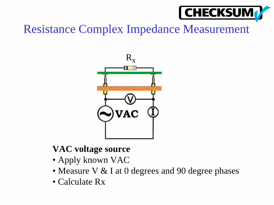
Resistance Complex Impedance Measurement
VAC voltage source• Apply known VAC• Measure V & I at 0 degrees and 90 degree phases• Calculate Rx
Rx

Capacitor Measurement
TV
Volts
Time
Complex-impedance measurement for most smaller capacitorsPulsed DC current measurement• Apply constant current• Measure change in voltage over time• Compute capacitance

Inductance Measurement
Complex-impedance measurementVAC voltage source• Apply known VAC• Measure V & I at 0 degrees and 90 degree phases• Calculate inductanceCan be used for inductors, relay coils, transformers
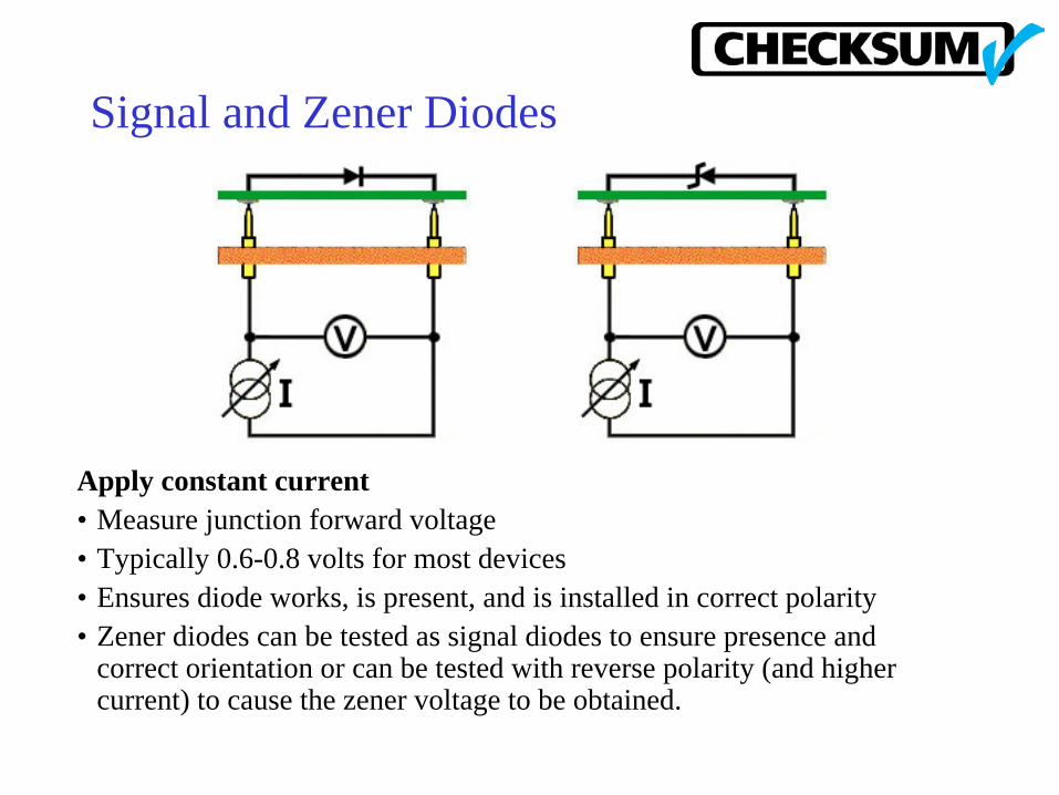
Signal and Zener Diodes
Apply constant current• Measure junction forward voltage• Typically 0.6-0.8 volts for most devices• Ensures diode works, is present, and is installed in correct polarity• Zener diodes can be tested as signal diodes to ensure presence and
correct orientation or can be tested with reverse polarity (and higher current) to cause the zener voltage to be obtained.

Light Emitting Diodes “LEDs”
• LEDs can be tested as diodes (typical forward voltage drop 1volt or more) for presence, and orientation
• Can be turned-on for the operator to observe color and brightness• Fixtures can optionally use special “light probes” that can measure LED
color and brightness automatically

Transformer Polarity
Apply VAC at the input• Measure phase at the output• Ensures proper wiringOther transformer tests• Measure resistance and inductance of input and output windings• Measure resistance between input and output windings

Measurement Refinements
Voltage or Current Range• Select a stimulus to provide adequate signal to make measurement, but not enough
to damage components or cause parallel components (like diodes) to interfere with measurements.
4-Wire Kelvin Measurement• Use separate test points to apply stimulus and make measurement. This eliminates
the lead and contact resistance errors from the measurement. The voltage input test points are high-impedance so resistance in these leads are ignored.
Guarding• Eliminates or reduces effects of parallel circuits from a component measurement• Applies a stimulus in parallel paths so that no current flows into the parallel path.• Multiple points can be guarded at once• Can be used with resistor, capacitor, diode, inductor measurements• Works with constant current, constant voltage, and complex impedance
measurements

Measurement Refinements, cont.
Scale and Offset• Measurement = (Measured Value minus Offset) x Gain Scale Factor• Each measurement can have its own zero-offset and scale factor to make
readings precise, or to scale (e.g. ohms to milli-ohms).
Combinations• Each measurement can have up to 16 test points active at one time as sources,
senses, guards, and/or guard senses.• All test points are equivalent, no special wiring is required.• In addition, each measurement can have its own frequency, current/voltage,
charge/discharge delay time, and measurement technique.

4-Wire (Kelvin) Connections
Rx Rx
The voltage drop due to the current flowing through the resistance of the fixture wires is not included in the measurement. The probe connection resistance is very small and only two probes are normally used (figure on the right). The voltage inputs are high-impedance so the resistance in these wires can be ignored. The 4-wire measurement can be used for accurate low-ohms measurements.

Rx Rx
Guarded MeasurementsEliminate Effect of Parallel Components
Without guarding, the parallel resistors make the measured value of Rx appear smaller.
With guarding, the current in the parallel resistors can be eliminated so the value of Rx can be accurately measured.

Measuring Active Devices - Transistors
Transistors• Sweep current through the base while monitoring current
through base/emitter. This will detect presence, polarity and proper operation.
• Measure as B-E diode and B-C diode

Measuring Active Devices - FETs
FETS• Sweep the voltage at the gate• Measure turn-on point at source/drain
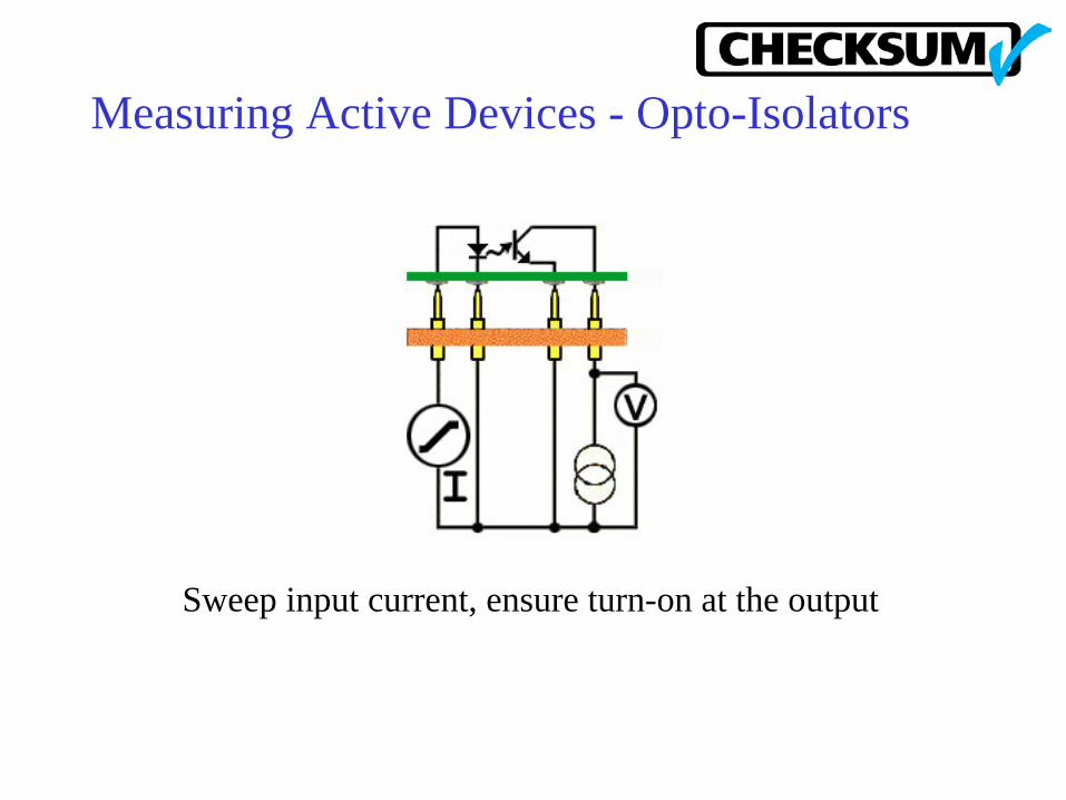
Measuring Active Devices - Opto-Isolators
Sweep input current, ensure turn-on at the output

Testing Relays
• Measure contact resistance for either normally open (NO) or normally closed (NC) connection
• Apply VDC to the relay coil• Measure contact resistance in new connection configuration

Opens and Shorts Testing“Continuity”
• Measure from each test point to all others to find shorts
• Measure each expected connection to find opens
• Programmable thresholds (standard is 10 ohms)
• Points can be specified as 'no-cares' if measured elsewhere or near the threshold value
• Special high-speed hardware and software algorithms are used since so many tests need to be made
• Continuity map is self-learned from known-good assembly or can be imported

IC Presence and Orientation
• System measures the internal protection diodes in ICs to determine pin connection
• Can be used to detect IC presence and polarity• Not infallible since parallel ICs can mask faults and
different ICs can have the same diode mapping• IC Diode Map is automatically self-learned by the system
GND
VCC

IC Connections UsingTestJet Technology
• Uses patented method to measure small capacitances from top of the part to traces on PCB. Open connections drastically reduce capacitance (e.g. from 80 fF to 5 fF)
• Tests for open IC connections even if the IC is bussed• Usually used on SMT assemblies since opens are more
prevalent in SMT than through-hole technology• Can also be used on connectors and other parts too small to
probe

Capacitor Polarity
• Can be detected for most capacitors, using TestJet Technology, by electrical measurements to determine physical geometry of capacitor. This technology can be used on most SMT capacitors and most axial capacitors.
• Sometimes capacitors can be measured for polarity by applying a constant-current, then measuring the voltage drop. If the capacitor is reversed, the developed voltage may be lower.

Potentiometers
• System can measure the resistance. If it is out of tolerance, the system will present a “meter” on the screen so the operator can adjust the setting within the tolerance before continuing.
• Meter 'polarity' can be changed so the direction of adjustment always matches the meter direction.

Switches and Jumpers
• Switch settings and jumpers can be measured with resistance. If incorrect, the system will automatically ask the operator to change the position of the switch or jumper.
Test System Software
Visual MDA™ Windows software• Simple for the Test Operator• Test Program Generator/Editor• Statistical Process Control Software (SPC)• System Configuration Software• Extensive on-line Help• Network-compatible

Main Test System Window

Test Operator Interface
• Easy screens to follow• Most operations can be done with either the keyboard,
mouse or keypad• System can be setup to automatically output reports (e.g.,
failure-only reports, only if the assembly fails), or reports can be manually selected
• On-line pareto chart can show frequency of recent failures to find process problems fast
• Test progress gauge and panel Pass/Fail window• Screen color and sound changes between Pass and Fail• System can be password-configured to limit operator
choices and options

Test Pass Window

Test Fail Window
Programming Language
• Familiar Excel-like data-entry screens• Program sequence can be specified Test-step oriented with
variety of test-steps such as Res for resistance, Cap for capacitance, ...
• Memory math capability• Conditional jump and label capability• Custom operator displays and inputs• Execute user-written .exe files• Create program libraries or link test programs without any
practical program length limit

• Manual or CAD-data program entry• CAD converters for most popular CAD systems standard
(Mentor, Schema, P-Cad, HP-BCF, OrCAD, Cadence, Racal-Redac, Viewlogic, Tango, ComputerVision, Pads200, Scicards,...)
• Programs can be entered or generated off-line with a PC not connected to test system
• Interactive program development - enter, execute and fine-tune test steps on-line
• Can automatically “panelize” (duplicate) the test for your assemblies that have multiple boards on a single panel
• Extensive on-line help
Test Program Generation

Test Programming

Statistical Process Control Software
• Standard with the system software• Production reports for analysis of production and yield• Pareto charts for failure analysis by frequency of failure• X-Bar/Sigma charts for plotting mean, standard deviation,
sigma and 3-sigma with Cp and Cpk. Can be used for program tolerance optimization or measurement analysis.
• Raw data stored in ASCII flat-files for your custom in-house analysis if desired.
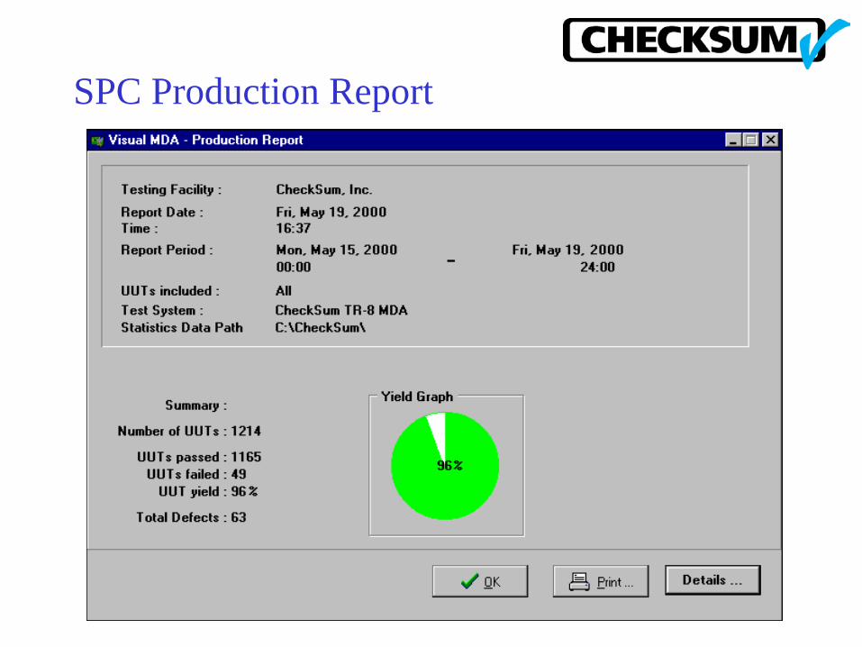
SPC Production Report

SPC X-Bar/Sigma Analysis

System Configuration Software
• Allows setting system environment and configuration• Self-test and built-in self-calibration of hardware• Password and login capability• Assign access by login name• Specify format of reports

System Configuration

Contact CheckSum
CheckSum, LLCPO Box 3279Arlington, WA 98223Tel: 360.435.5510 Fax: 360.435.5535Email: [email protected]
www.CheckSum.com