CHECK GAGE (TEMPLATE) DESIGN TRAINING … CHECK GAGE (TEMPLATE) DESIGN TRAINING MANUAL Contents: 1....
50
1 CHECK GAGE (TEMPLATE) DESIGN TRAINING MANUAL Contents: 1. Part downloading procedure 2. Check gage modeling using ProE 3. Check-in of gages 4. Check-out and modification of existing gage 5. Reference examples
Transcript of CHECK GAGE (TEMPLATE) DESIGN TRAINING … CHECK GAGE (TEMPLATE) DESIGN TRAINING MANUAL Contents: 1....

1
CHECK GAGE (TEMPLATE) DESIGN TRAINING MANUAL
Contents:
1. Part downloading procedure 2. Check gage modeling using ProE 3. Check-in of gages 4. Check-out and modification of existing gage 5. Reference examples

2
1. Part downloading procedure
a) Search the part in PDMLink, Click “Add to Work Space”. Select Object Type All and Location 90 degrees and click on “Go” as shown:
b) Enter part# and click on” OK” and select the appropriate check boxes as shown
below:

3
c) Selected items will be added to the workspace as shown:
Note: The decision number in RECON may not always correct. Go by the PDMLink model decision number. Following snapshots would guide to add the part to the workspace.
d) Open the ProE model and take back up to your hard drive. e) Open the drawing file.
Check these boxes to add required items to the workspace
4
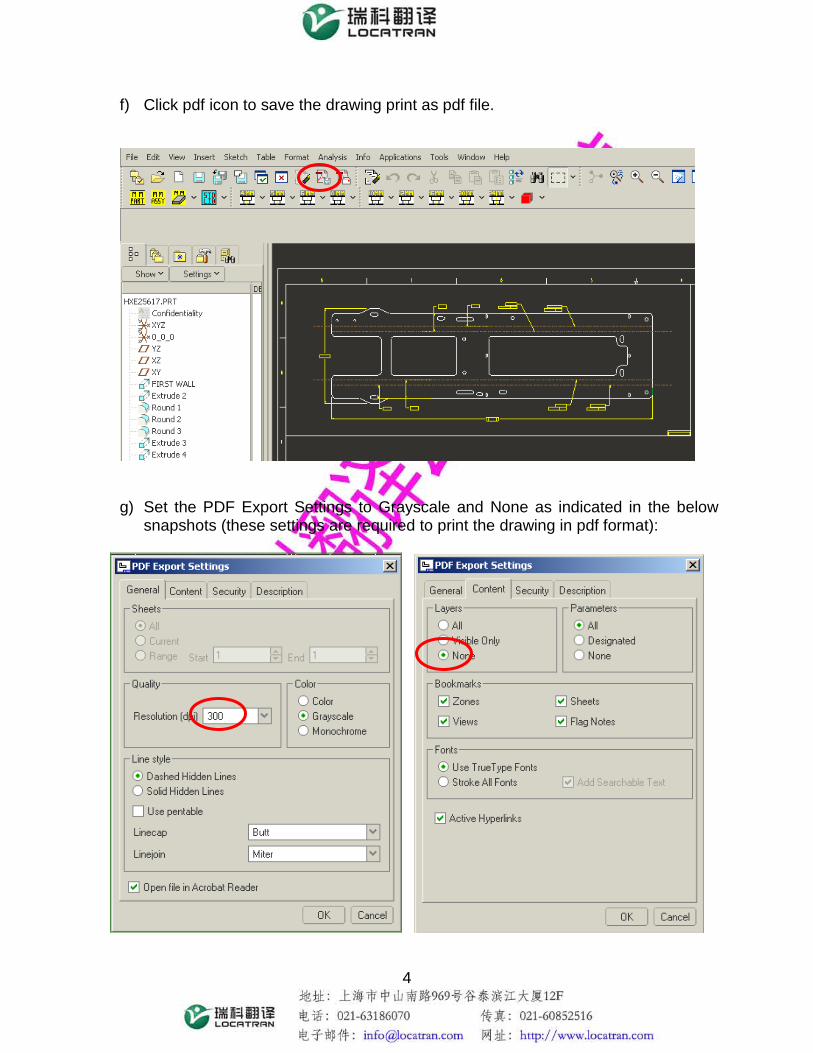
f) Click pdf icon to save the drawing print as pdf file.
g) Set the PDF Export Settings to Grayscale and None as indicated in the below
snapshots (these settings are required to print the drawing in pdf format):
5
2. Check gage modeling procedure Note: File names should be as per unit specific guidelines. Dimensions and gage thickness should be selected as per unit specific guidelines. Note: For the following gage modeling procedure is as per Harvester Works practices.
a) Open ProE model (Partnumber.prt)
b) Create new part file with naming syntax “Partnumber_Toolnumber_ref.prt”
c) Save (Partnumber_Toolnumber_ref.prt file created in previous step) and
close.
d) Create a new assembly file with naming syntax
“Partnumber_Toolnumber.asm”, it may be different as per unit specific guidelines)
e) Using assemble component option insert the following files at DEFAULT Constraint settings: i. Partnumber.prt ii. Partnumber_Toolnumber_ref.prt
f) Copy solid surfaces to the reference part (Partnumber_Toolnumber_ref.prt) by using the following procedure: i. ACTIVATE Partnumber_Toolnumber_ref.prt ii. HIGHLIGHT any of surfaces that form the boundaries for the reference
part iii. RIGHT CLICK on the highlighted surface. Here, if it is not possible to
select any surfaces, check on the right side of the dashboard (command Board). Select option as Geometry.
iv. Select SOLID SURFACES option v. COPY (Ctrl+C) the surfaces vi. Select “copy” from gage model tree and select “solidify” from edit menu. vii. PASTE (Ctrl+V) them on to partnum_toolnum_ref.prt
g) Save and close Partnumber_Toolnumber.asm

6
h) Create a new part file with naming syntax ‘Toolnumber_001.prt’
i) Save Toolnumber_001.prt and close
j) Create a new assembly file with naming syntax ‘Toolnumber.asm
k) Using insert component option assemble the following at DEFAULT settings
i. Partnumber_Toolnumber_ref
ii. Toolnumber_001.prt
l) Activate Toolnumber_001.prt
m) Create the necessary datum planes and references
n) Using the standard design options such as extrude , etc create the
features which constitute the gage.
o) These step by step procedures are explained in the step no. 6 (reference examples section.)
Grid pattern should be on the part surface once paste command (step f–vi) is executed; for convenience picture of the successful reference part creation is shown in this picture.
This picture shows the incorrect copying of part

7
p) Save and Toolnumber.asm
3. Gage check-in procedure
i. Click on drop down menu and select ‘Edit Preferences’ Tab
ii. When ‘Edit Preferences’ tab is selected, following window will appear.
iii. Fill folder information in Context, Part target Folder, CAD Document Target Folder, View for Parts and hit apply button.(above snap shot shows specific for Harvester works only.)

8
(Step i through iii is a onetime activity)
a) Select all files and click on the Check-In icon as shown below:
b) Once you click on the Check-In below screen will appear.
c) Click on the ‘Finish’ button to Check-In the parts. d) Check the remark “Check-In successful “in the Display Toolbar of ProE. If due
to some reasons the Check-in fails, then refer “Event manager “. 4. Check-out and modification of existing gage
1. Enter the gage tool number in Number tab as shown:

9
2. Add part into workspace(follow procedure 2b through 2c) 3. Select part model and press checkout as shown.
4. You will see the Checkout succeeded message into the taskbar as shown:
5. Reference examples Note: For the following gage modeling procedure is as per Harvester Works practice.

10
Exercise 1 Check Gage for measuring an outer profile. The following picture shows the customer’s requirement of check gage for a sheet metal part. The red part in the diagram shows an overview of the gage. The features to be checked are the Bend radius (Outer), and the leg lengths at both sides. The following steps clarify step by step procedure for modeling the gage in Pro-E: • Pro-E model of the part: • Create a view conveniently as shown in the requirement sheet.
Leg length
Bend Radius (Outer)

11
Then using Extrude option and by using enough references, draw the sketch of the gage. Use “Create an Entity from an edge” to pick the outline of the model for drawing the profile easily. Follow all the rules while drawing as mentioned in the file enterprise guidelines. • Extrude the gage to 2mm thickness towards component side. • Add “Round” on all corners to avoid sharp edges. • Add “Chamfer” at the end of the notches.
Rounding corner to the radius of 6mm
Chamfering at notches to 1x45°

12
• Add a thru hole of 10mm at one end. • The gage number has to be marked at any one surface of the gage. Use “Sketch”
option under Cosmetic in the Insert menu. The length of the letters should be at least 10mm.
Now the gage is completely designed. Check once whether it is modeled as per the customer’s requirement, measuring all the intended features. Ensure all the features are included in the model. After completion the model tree should look similar as follows:

13
Exercise 2: Check Gage for measuring an internal feature along with an outer profile.
The above request drawing shows that the gage should be measuring the outer bend radius, leg length along with an internal hole. All these features have to be checked simultaneously.

14
• Follow the same procedures as mentioned in the exercise1, to draw the sketch of the gage.
• Pick the edges of the hole as the references. It will make an Orange colored reference
line in the sketching plane. This can be done using References under Sketch menu.
Reference edges
15
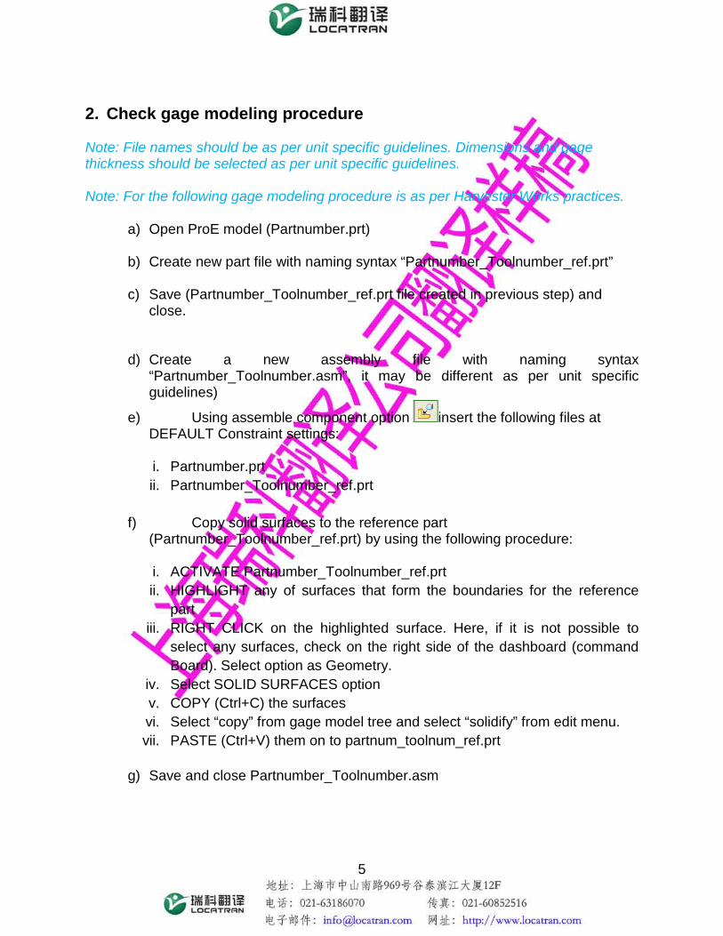
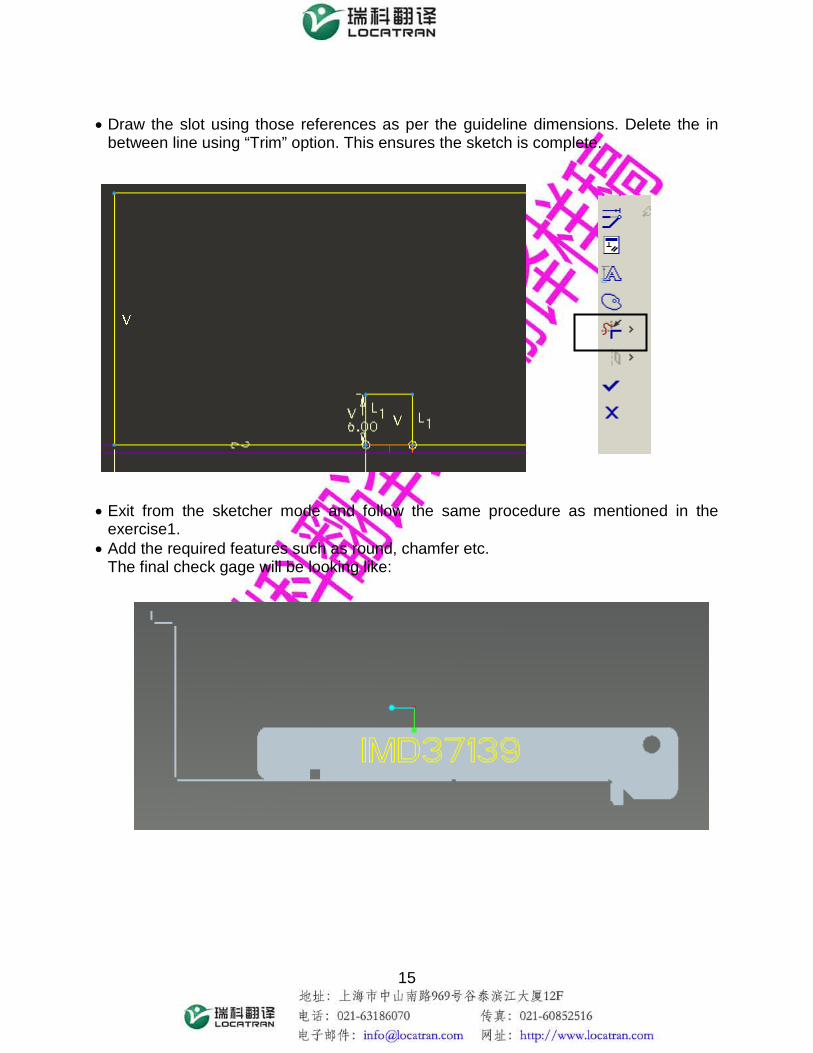
• Draw the slot using those references as per the guideline dimensions. Delete the in
between line using “Trim” option. This ensures the sketch is complete. • Exit from the sketcher mode and follow the same procedure as mentioned in the
exercise1. • Add the required features such as round, chamfer etc.
The final check gage will be looking like:
16
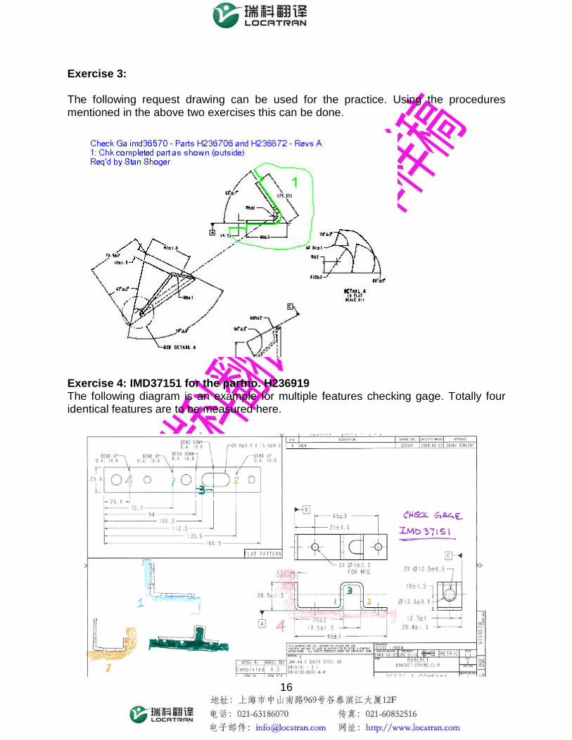
Exercise 3: The following request drawing can be used for the practice. Using the procedures mentioned in the above two exercises this can be done. Exercise 4: IMD37151 for the partno. H236919 The following diagram is an example for multiple features checking gage. Totally four identical features are to be measured here.

17
1. Final component has to be checked for all the bends with the internal holes.
2. Only the first bend has to be checked with the internal features. And hence all the remaining bends should not be there in the component. Thus the part at this stage looks as shown below: (The unbending procedure is mentioned later)
3. The second bend alone has to be checked with the internal holes.

18
4. The third bend alone has to be checked with the internal holes in the part.
All these things have to be incorporated and should be designed as a single gage. Steps to be followed in designing the gage: • Complete the first requirement of checking the entire profile, using the default method.
Follow all the rules given in the guidelines as usual. Don’t create round, chamfer etc. now.
[Note: Don’t use “Create entity option”, since the part will be unbent in the next stage. Use the edges as references and draw lines manually for the same length. And don’t forget to delete the references while exiting from the sketcher mode. This will avoid model failing at later stage.]

19
• Then the component should be unbent for modeling the second one. The model can be unbent only in the *.prt file. Hence open the part (PartNumber.prt) model.
• Choose the unbend option from the toolbar. • Click “Done” in the Menu manager. A Popup menu opens up as shown below. • Click on the fixed portion of the part which remains unaltered even after unbent. Then
click done for unbend geometry definition. • Select the bend regions to be removed. If you want to unbend more than one radius
press “Ctrl” and select all the bend radii. After selecting, click on “Done Refs”.
20
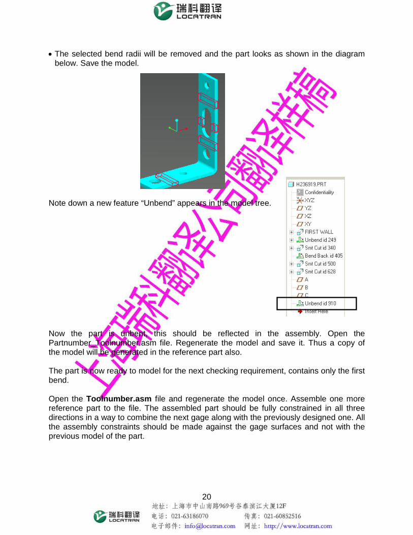
• The selected bend radii will be removed and the part looks as shown in the diagram below. Save the model.
Note down a new feature “Unbend” appears in the model tree. Now the part is unbent, this should be reflected in the assembly. Open the Partnumber_Toolnumber.asm file. Regenerate the model and save it. Thus a copy of the model will be generated in the reference part also. The part is now ready to model for the next checking requirement, contains only the first bend. Open the Toolnumber.asm file and regenerate the model once. Assemble one more reference part to the file. The assembled part should be fully constrained in all three directions in a way to combine the next gage along with the previously designed one. All the assembly constraints should be made against the gage surfaces and not with the previous model of the part.

21
Now the second gage can be drawn. At this time, the previously drawn gage should be chosen as the sketching plane, so that it will become as a single part. Draw the required features to be checked as usual, and keep in mind not to use the “Create entity from edge” option. Also delete all the references used while coming out of sketcher mode. Extrude the gage in the same direction as that of the first one, and thus the gage looks as below.

22
After this the third part of the check gage has to be done. For this the part should have only the second bend. Open the “Partnumber.prt” file. Delete the previous unbend created from the model tree. Follow the same procedure for un-bending all the features except the required bend. Save the file with the same name. Regenerate the assembly and once again save it.

23
Open the imdno.asm and assemble the reference part now. Fix all the constraints in such a way that it is easy to draw the required check gage combined with the existing model. The assembly should be fully constrained in all three directions. Select the existing gage surface as the sketching plane for the new extrusion. Sketch the features to be checked following the same procedure. Extrude it in the same direction of the existing gage. Don’t use “Create entity option” and delete all references used while exiting sketcher mode.

24
Now the last part of the gage has to be modeled. Open the partno.prt file and unbent the features whichever is not required for checking. Regenerate the model and save it. Also open the Partnumber_Toolnumber.asm, regenerate and save the file. Open Toolnumber.asm file. Assemble the part and impose the constraints in such a way one more checking feature can be included with the existing gage model easily.

25
Following the same procedure, select the existing gage surface as the sketching plane. Draw the new features to be included in the gage using the newly assembled part model. Extrude the sketch in the same direction of the gage to 2mm. Add the other required features like rounding off all the corners, chamfering near the notches etc. Engrave the Tool number on any one surface of the gage. The gage is completely modeled now. Open the Partnumber.prt file, delete all unbends made and save the file. Regenerate the part & the assembly model and save it. The fully modeled gage looks as shown in the diagram below.

26
Exercise 5: IMD36957 for the part H149499 The above request diagram shows that multiple features to be checked. The request diagram can be divided in to three parts as shown below First part to
be designed
Second part of the gage
Third part of the gage

27
First check of the gage: Select the apt view and sketching plane before starting of the gage design. Give enough references required and sketch the checking profile. Also take the references of the internal profiles on the sketching plane. Extrude the sketch to 2mm towards the component side. Don’t add round, chamfer etc. at this stage.
Select this surface as the sketching plane
Top Plane
Front Plane

28
Second check of the gage: Now select the convenient view for the second part of the gage. Since the part is bigger in size, it is advisable to assemble one more model of the partly designed gage instead of a part. Activate the assembly and insert Toolnumber_001.prt. Place the constraints in such a way that it is easy to draw the gage with respect to the saved view.
Align the side face of the gage with the left side edge of the saved view.
Front Side
Right Side
29
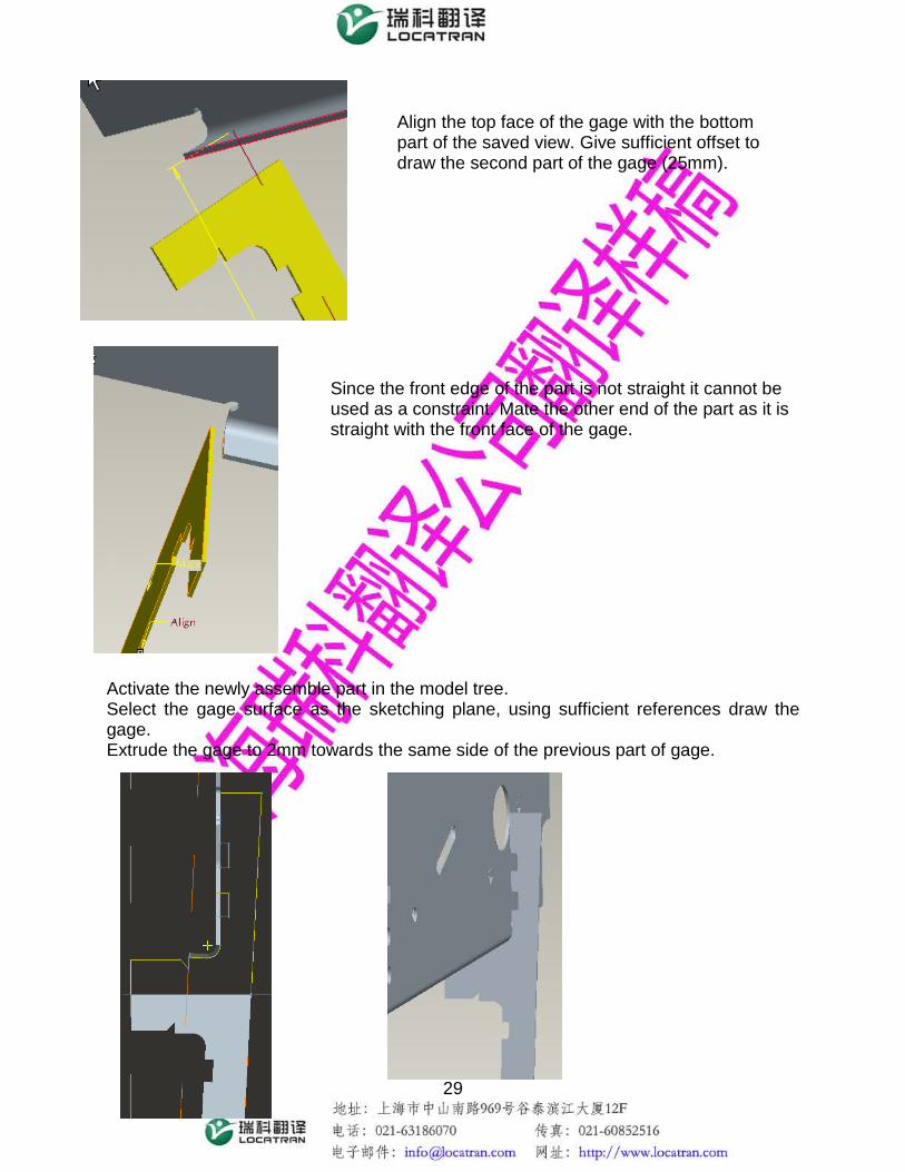
Activate the newly assemble part in the model tree. Select the gage surface as the sketching plane, using sufficient references draw the gage. Extrude the gage to 2mm towards the same side of the previous part of gage.
Align the top face of the gage with the bottom part of the saved view. Give sufficient offset to draw the second part of the gage (25mm).
Since the front edge of the part is not straight it cannot be used as a constraint. Mate the other end of the part as it is straight with the front face of the gage.

30
Third check of the gage: Assemble one more model of the gage. Create a convenient view for designing the third part. Give the assembly constraints as below.
Front side
Left side
Align the straight end at the opposite end of the selected view with the front surface of the gage.
Mate the straight end at the bottom end of the selected view with the top surface of the gage and give the sufficient offset (200mm)

31
Select the existing gage surface as the sketching plane. Using adequate references draw the sketch adjacent to the previous edge of the gage. Extrude to 2mm towards the same side of the gage.
• Add radius of 6mm in all the corners, 1m chamfer near the notches. • Insert a hole of diameter 10mm in any one surface of the gage. • Etch the gage number.
Mate the side surface of the gage with the left side surface of the selected view and give the offset 25mm to draw the gage in between.
32
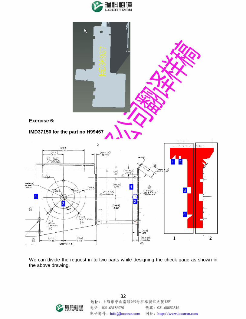
Exercise 6: IMD37150 for the part no H99467 We can divide the request in to two parts while designing the check gage as shown in the above drawing.
1 2

33
First check: Create the appropriate view for sketching the first check. Create a plane for sketching the gage.
Top Side
Right Side
Create a plane perpendicular to the side face and passing through the centre of the measured hole

34
First create an axis line for the hole using the Datum axis tool option. Create a datum plane which is parallel to the side surface of the slot as indicated in the diagram and also passing through the axis of the hole.
Parallel to the surface and passes thru the axis of the hole

35
Select the newly created datum as the sketching plane and draw the gage. Second check: Assemble one more model of the part. Give the constraints as shown below. Thus the model is constrained in all three directions.
Align the two front faces
Mate the top surface of the gage and the bottom of the assembled model and give an offset of 25mm to draw the gage in between.
Align the two side surfaces

36
Select the appropriate view for drawing the sketch as shown below. Draw the profile of the gage. Extrude for 2mm towards the previous gage side. Add chamfer, rounding off corners, and a 10mm hole. Mark the Gage no in the gage surface.
Front side
Top side
37
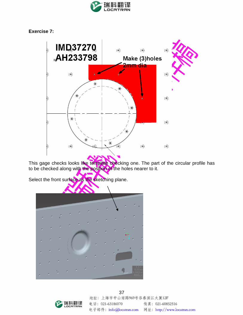
Exercise 7: This gage checks looks like template checking one. The part of the circular profile has to be checked along with the position of the holes nearer to it. Select the front surface as the sketching plane.
38
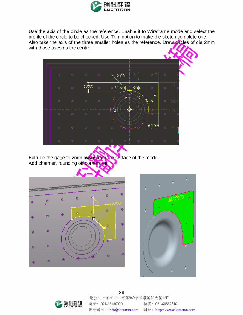
Use the axis of the circle as the reference. Enable it to Wireframe mode and select the profile of the circle to be checked. Use Trim option to make the sketch complete one. Also take the axis of the three smaller holes as the reference. Draw circles of dia 2mm with those axes as the centre. Extrude the gage to 2mm away from the surface of the model. Add chamfer, rounding off corners etc.
39
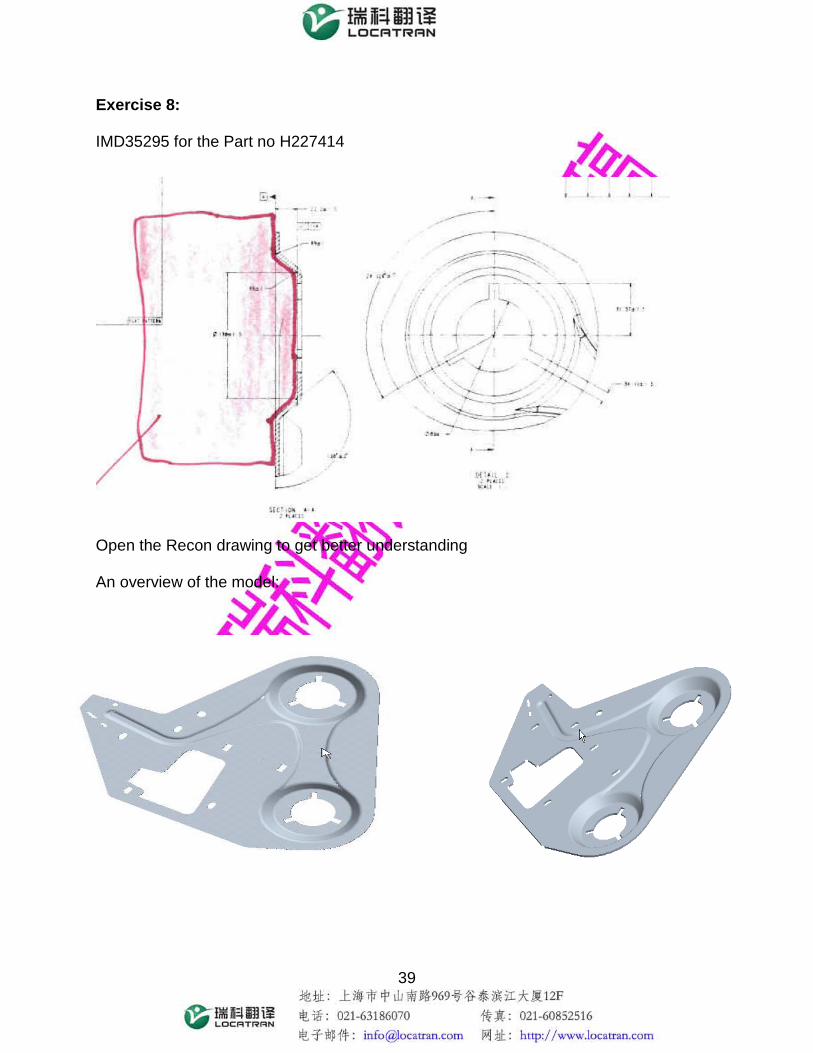
Exercise 8: IMD35295 for the Part no H227414 Open the Recon drawing to get better understanding An overview of the model:

40
The final Check gage should be looking as shown in the diagram below. Procedure to make the gage: First of all we need to create a plane at the desired location for sketching the gage.
To get the reference of the internal features we need to get the cross section. Create X Sec in assembly mode:
Go to View manager Xsec

41
Hit “Enter” key on the newly created cross section name Xsec001.
Select the plane you have created and click on “Done” Right click on the created section and enable Visibility. Now a sketch of the Cross section can be seen as shown below.
Go to insert datum curve done

42
Select the section name that you have already createdXsec0001. Go to View manager right click on the sectionDisable the visibility option. Only then that cross section can be taken as reference entities and the exact profile can be drawn.
Now it is possible to select this Cross section and draw the gage as required in the Sketcher mode. Select the newly created datum as the sketching plane.

43
Extrude the gage to 2mm and add other required features round, chamfer etc.

44
Exercise 9: IMD37968 for the part no.H179192 This is a multiple feature checking gage and can be divided into three checks: Check 1:
With respect to the bend radius the two edges (4&5) and the leg length has to be checked
Bend Radius
45
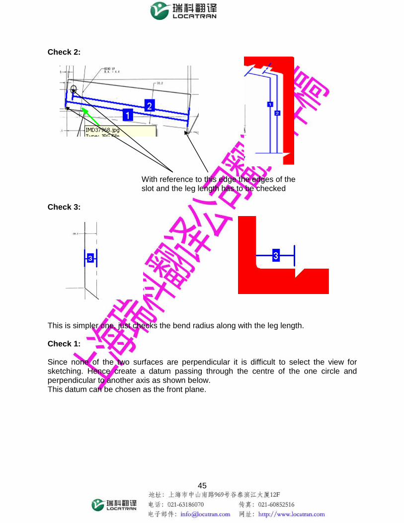
Check 2: Check 3: This is simpler one, just checks the bend radius along with the leg length. Check 1: Since none of the two surfaces are perpendicular it is difficult to select the view for sketching. Hence create a datum passing through the centre of the one circle and perpendicular to another axis as shown below. This datum can be chosen as the front plane.
With reference to this edge the edges of the slot and the leg length has to be checked

46
Create one more datum perpendicular to that, to get the top plane. Select the front plane of the model as the sketching plane, and choose a view using the two newly created datum planes.

47
Draw the sketch of the checking profile. Since the front surface is not parallel to the sketching plane the leg length will not be exact if we use the “create entity from edge” option. Hence measure the length of the line and draw a line manually of the same length. Extrude the gage to 2mm towards the component side.

48
Check 2: Assemble on more model of the part. Choose a convenient view as shown in the figure below. Select the existing gage surface as the sketching plane and draw the gage profile using enough references.
Mate the two top surfaces and give an offset of 30mm to draw the gage in between
Align the two side faces
Align the front face of the gage with the back portion of the assembled part
Front plane
Top plane

49
Extrude it to 2mm towards the same side of the gage. Check 3: Assemble one more model and give the constraints as shown below.
Mate the front face of the gage with the front datum plane of the assemble component. Since none of the surfaces are parallel as required use datum planes
Align the bottom face of the gage with the top of the newly assembled model

50
Use the same view as that of the previous one and select the existing gage surface as the sketching plane. Draw the profile and extrude it. Add the other features.
Align the bottom face of the gage with the top of the newly assembled model and give an offset of 35mm.
Third portion of the gage can be drawn conveniently