CHATFIELD CENTER FOR THE ARTS Chatfield Center for the Arts ...
183
I hereby certify that this report was pre- pared by me or under my direct supervi- sion and that I am a duly licensed architect under the laws of the state of Minnesota. Name:_______________ Date: 11/21/14 Registration No.: 18730 LHB 701 Washington Ave N, Suite 200 Minneapolis, MN 55401 (P) 612.338.2020 (F) 612.338.2088 CHATFIELD CENTER FOR THE ARTS Chatfield Center for the Arts Predesign Report (Revised) November 21 st , 2014 prepared by LHB
Transcript of CHATFIELD CENTER FOR THE ARTS Chatfield Center for the Arts ...

I hereby certify that this report was pre-pared by me or under my direct supervi-sion and that I am a duly licensed architect under the laws of the state of Minnesota.
Name:_______________Date: 11/21/14 Registration No.: 18730
LHB701 Washington Ave N, Suite 200
Minneapolis, MN 55401(P) 612.338.2020(F) 612.338.2088
C H A T F I E L D C E N T E R F O R T H E A R T S
Chatfield Center for the Arts Predesign Report(Revised) November 21st, 2014
prepared by LHB

PERFORMANCE DRIVEN DESIGN.Prepared by LHB C H A T F I E L D C E N T E R F O R T H E A R T S
SECTION 1: PREDESIGN SUMMARY STATEMENT
PREDESIGN SUMMARY STATEMENT .............................................................1.1PROJECT SCHEDULE .......................................................................................1.4BUILDING/PROJECT AUDIT SHEET .................................................................1.7BUILDING/PROJECT AUDIT SHEET–COSTS .................................................1.9
SECTION 2: BASIS FOR NEED–PROJECT BACKGROUND NARRATIVEBASIS FOR NEED–PROJECT BACKGROUND NARRATIVE ...........................2.1HISTORICAL CONTEXT.....................................................................................2.6
SECTION 3: AGENCY/ORGANIZATION PLANNINGOPERATIONAL PROGRAM ...............................................................................3.1
SECTION 4: PROJECT DESCRIPTIONPROJECT DESCRIPTION ..................................................................................4.1APPLICABLE CODES ........................................................................................4.7HISTORICAL CONSIDERATIONS....................................................................4.12MECHANICAL CONSIDERATIONS .................................................................4.19ELECTRICAL CONSIDERATIONS ...................................................................4.23GEOTECHNICAL EVALUATION.......................................................................4.26GENERAL STRUCTURAL REQUIREMENTS ..................................................4.28DIAGRAMMATIC PLANS & SECTIONS ...........................................................4.33SUSTAINABILITY, ENERGY CONSERVATION, AND CARBON EMISSIONS .4.57MINNESOTA SUSTAINABLE BUILDING GUIDELINES ...................................4.58STATUTE REQUIREMENTS ............................................................................4.60PROJECT PROCUREMENT AND DELIVERY .................................................4.61
SECTION 5: SITE ANALYSIS AND SELECTIONSITE ANALYSIS AND SELECTION
SECTION 6: FINANCIAL INFORMATIONCOST ESTIMATES PHASE I ..............................................................................6.1COST ESTIMATES PHASE II .............................................................................6.3CCA CURRENT OPERATING BUDGET ............................................................6.5
SECTION 7: SCHEDULESCHEDULES ......................................................................................................7.1
TABLE OF CONTENTS
PERFORMANCE DRIVEN DESIGN.Prepared by LHB C H A T F I E L D C E N T E R F O R T H E A R T S
D
APPENDIXPREDESIGN MEETING MINUTES .......................................................................1GEOTECHNICAL REPORT .................................................................................17SURVEY ..............................................................................................................45HERITAGE LANDMARK NOMINATION REPORT ..............................................46
TABLE OF CONTENTS
PERFORMANCE DRIVEN DESIGN.Prepared by LHB C H A T F I E L D C E N T E R F O R T H E A R T S
Section 1, p 1
PROJECT SUMMARYPERFORMING ARTS CENTER
The Chatfield Center for the Arts project will address three major initiatives with important historic preservation and accessibility outcomes:
1. Renovation of the 1936 Auditorium, focusing on modernization of its electrical, stage lighting, acoustical, fire and life safety, and HVAC systems; restoration of the windows and doors; conversion of the former gymnasium area into specialized back of stage facilities; and installation of new restroom facilities on the lower level.
2. Rehabilitation of the 1916 School Building to house auditorium support functions and provide new office space, community rooms, and common areas with full ADA accessibility; including electrical, lighting, and HVAC system upgrades, installation of appropriate windows and doors, additional restrooms, and restoration of the original gymnasium.
3. Construction of an appropriately designed infill lobby addition between the two buildings that will preserve and integrate the historic architectural elements while promoting overall sustainability.
The project, which will be completed in multiple phases over several years, will create a major regional performing arts venue and cultural attraction that will provide community organizations and touring attractions with modern theatrical production facilities, as well as space for meetings, lectures, exhibitions, parties, galas, conventions, and other special events.
The 1916 School Building and 1936 Auditorium have been determined eligible for listing in the National Register of Historic Places as a single historic resource. The city intends to prepare the necessary registration documents and request the SHPO to nominate the property to the National Register at the earliest possible date. As such, the Secretary of the Interior’s Standards for the Treatment of Historic Properties will guide decisions made as part of the project design and construction process.
COSTBased on the scope of work needed, the project is proposed to be completed in two separate phases. The first phase will focus on the accessibility and the auditorium. The second will center on site improvements, the 1916 school, a new connecting link between the existing buildings, and additional improvements in the auditorium.
SECTION 1: PREDESIGN SUMMARY STATEMENT
Inventory Number
The subject property has been assigned numbers FL-CHC-49 (auditorium) and FL-CHC-50 (high school) in the Fillmore County inventory of historical and architectural resources maintained by the State Historic Preservation Office.

PERFORMANCE DRIVEN DESIGN.Prepared by LHB C H A T F I E L D C E N T E R F O R T H E A R T S
Section 1, p 2
COST SUMMARY PHASE I
PHASE I COST ESTIMATE SUMMARY
PREDESIGN $44,000
DESIGN FEES $410,516
PROJECT MANAGEMENT $103,260
CONSTRUCTION COSTS
CONSTRUCTION (General Construction, Site, Utilities, Mechanical, Electrical, Plumbing, Etc.)
$3,749,000
CONTINGENCY (10%) $374,900
HAZARDOUS MATERIALS ABATEMENT (Allowance) $25,000
CONSTRUCTION MANAGEMENT FEE $187,450
OWNER CONTINGENCY (Allowance) $50,000
ART (1%) $37,490
OCCUPANCY (FFE; Communications) $360,000
TOTAL $5,341,616
SECTION 1: PREDESIGN SUMMARY STATEMENT
PERFORMANCE DRIVEN DESIGN.Prepared by LHB C H A T F I E L D C E N T E R F O R T H E A R T S
Section 1, p 3
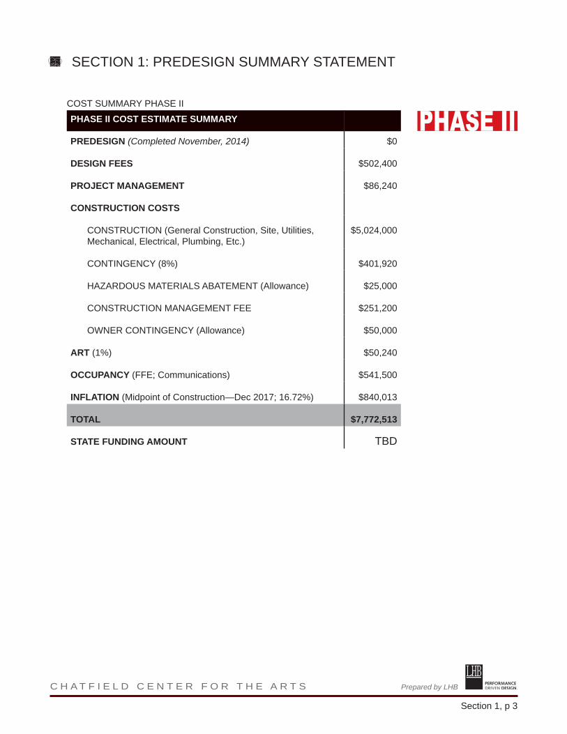
COST SUMMARY PHASE II
PHASE II COST ESTIMATE SUMMARY
PREDESIGN (Completed November, 2014) $0
DESIGN FEES $502,400
PROJECT MANAGEMENT $86,240
CONSTRUCTION COSTS
CONSTRUCTION (General Construction, Site, Utilities, Mechanical, Electrical, Plumbing, Etc.)
$5,024,000
CONTINGENCY (8%) $401,920
HAZARDOUS MATERIALS ABATEMENT (Allowance) $25,000
CONSTRUCTION MANAGEMENT FEE $251,200
OWNER CONTINGENCY (Allowance) $50,000
ART (1%) $50,240
OCCUPANCY (FFE; Communications) $541,500
INFLATION (Midpoint of Construction—Dec 2017; 16.72%) $840,013
TOTAL $7,772,513
STATE FUNDING AMOUNT TBD
SECTION 1: PREDESIGN SUMMARY STATEMENT

PERFORMANCE DRIVEN DESIGN.Prepared by LHB C H A T F I E L D C E N T E R F O R T H E A R T S
Section 1, p 4
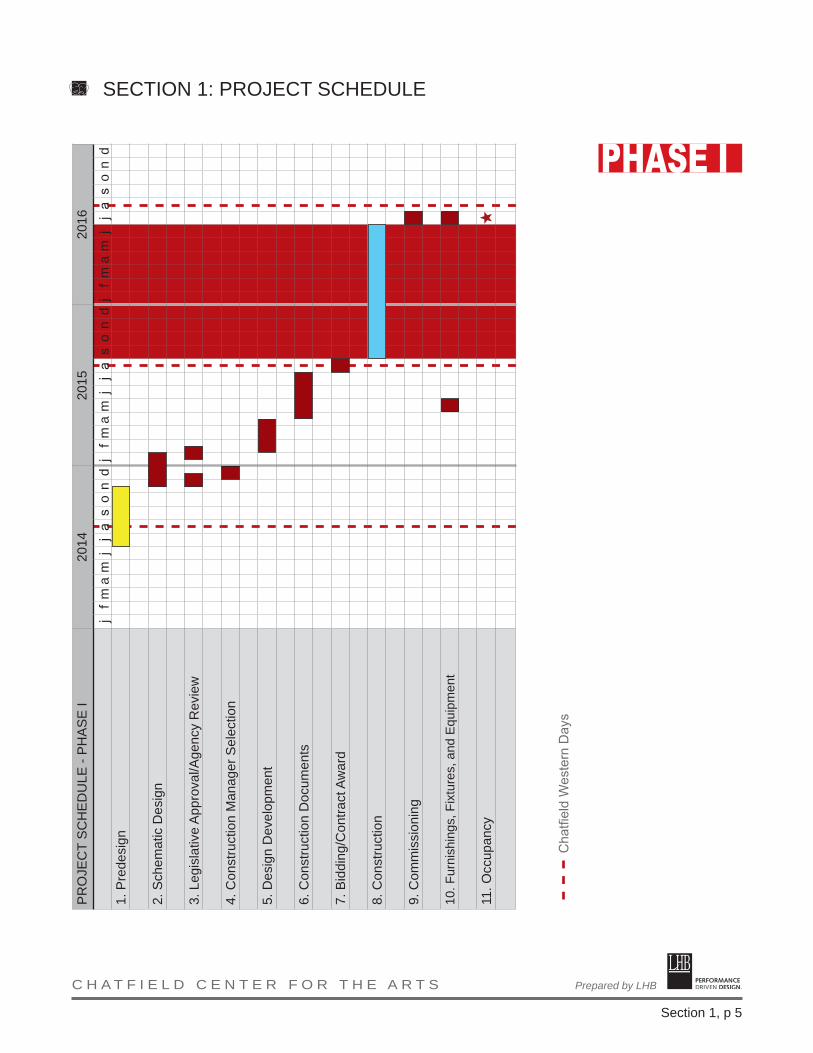
PHASE I
Schematice design will begin in November, 2014, for Phase I. Given the complexity of the project, the construction manager will be selected in December, prior to completion of schematic design. After initial conversations with the construction manager, schematic design will conclude in January, 2015, marked by the designated approval process.
Design development will begin in February and will be complete in April, 2015, with construction documents beginning immediately. Completion of design drawings and specifications will be complete by the end of July allowing bidding and contract processing in August, and will keep the existing facility open for Western Days 2015.
Construction and occupancy of the facility will be complete by August, 2016, in advance of Western Days.
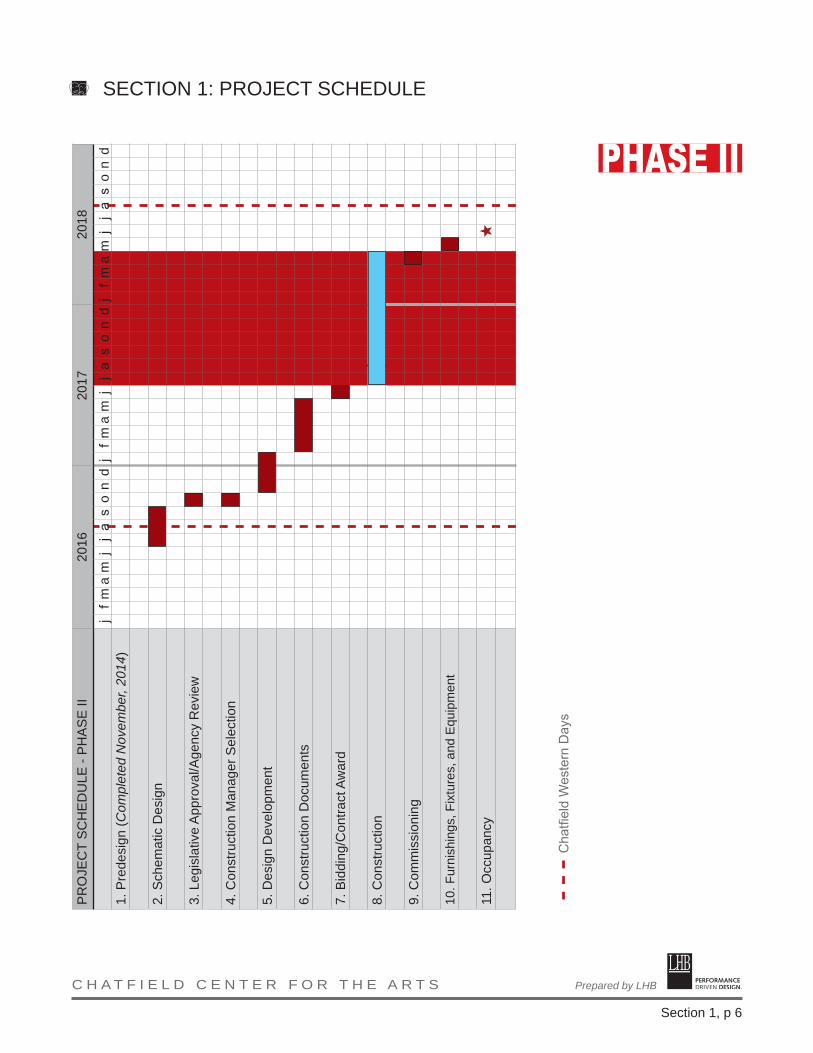
Phase II
Dependant on future funding, schematic design for Phase II will progress from July through September, 2016 with legislative approval/agency review and construction manager selection taking place in October. Design development picks up in November and continues through January, 2017.
Construction documents will begin in February and will finish at the end of May, 2017. Bidding/contract award will happen in June with construction to commence in July of 2017. Construction activities will be coordinated with Western Days, to allow the use of most, if not all, of the school during the community festival. Commissioning, furnishings, fixtures, and equipment will conclude the process with all construction activities to wrap up by the end of May, 2018.
Occupancy is projected at June, 2018.
SECTION 1: PROJECT SCHEDULE
PERFORMANCE DRIVEN DESIGN.Prepared by LHB C H A T F I E L D C E N T E R F O R T H E A R T S
Section 1, p 5
PR
OJE
CT
SC
HE
DU
LE -
PH
AS
E I
2014
2015
2016
1. P
rede
sign
2. S
chem
atic
Des
ign
3. L
egis
lativ
e A
ppro
val/A
genc
y R
evie
w
4. C
onst
ruct
ion
Man
ager
Sel
ectio
n
5. D
esig
n D
evel
opm
ent
6. C
onst
ruct
ion
Doc
umen
ts
7. B
iddi
ng/C
ontra
ct A
war
d
8. C
onst
ruct
ion
9. C
omm
issi
onin
g
10. F
urni
shin
gs, F
ixtu
res,
and
Equ
ipm
ent
11. O
ccup
ancy
j f
m a
m j
j
a s
o n
d
Cha
tfiel
d W
este
rn D
ays
j f
m a
m j
j
a s
o n
dj
f m
a m
j
j a
s o
n d
SECTION 1: PROJECT SCHEDULE
PERFORMANCE DRIVEN DESIGN.Prepared by LHB C H A T F I E L D C E N T E R F O R T H E A R T S
Section 1, p 6
PR
OJE
CT
SC
HE
DU
LE -
PH
AS
E II
2016
2017
2018
1. P
rede
sign
(Com
plet
ed N
ovem
ber,
2014
)
2. S
chem
atic
Des
ign
3. L
egis
lativ
e A
ppro
val/A
genc
y R
evie
w
4. C
onst
ruct
ion
Man
ager
Sel
ectio
n
5. D
esig
n D
evel
opm
ent
6. C
onst
ruct
ion
Doc
umen
ts
7. B
iddi
ng/C
ontra
ct A
war
d
8. C
onst
ruct
ion
9. C
omm
issi
onin
g
10. F
urni
shin
gs, F
ixtu
res,
and
Equ
ipm
ent
11. O
ccup
ancy
j f
m a
m j
j
a s
o n
d
Cha
tfiel
d W
este
rn D
ays
j f
m a
m j
j
a s
o n
dj
f m
a m
j
j a
s o
n d
SECTION 1: PROJECT SCHEDULE
PERFORMANCE DRIVEN DESIGN.Prepared by LHB C H A T F I E L D C E N T E R F O R T H E A R T S
Section 1, p 7
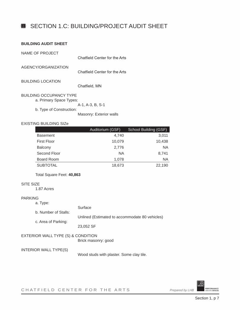
BUILDING AUDIT SHEET
NAME OF PROJECT Chatfield Center for the Arts
AGENCY/ORGANIZATIONChatfield Center for the Arts
BUILDING LOCATION
Chatfield, MN
BUILDING OCCUPANCY TYPEa. Primary Space Types:
A-1, A-3, B, S-1b. Type of Construction:
Masonry: Exterior walls
EXISTING BUILDING SIZeAuditorium (GSF) School Building (GSF)
Basement 4,740 3,011First Floor 10,079 10,438Balcony 2,776 NASecond Floor NA 8,741Board Room 1,078 NASUBTOTAL 18,673 22,190
Total Square Feet: 40,863
SITE SIZE1.87 Acres
PARKINGa. Type:
Surfaceb. Number of Stalls:
Unlined (Estimated to accommodate 80 vehicles)c. Area of Parking:
23,052 SF
EXTERIOR WALL TYPE (S) & CONDITIONBrick masonry: good
INTERIOR WALL TYPE(S)
Wood studs with plaster. Some clay tile.
SECTION 1.C: BUILDING/PROJECT AUDIT SHEET

PERFORMANCE DRIVEN DESIGN.Prepared by LHB C H A T F I E L D C E N T E R F O R T H E A R T S
Section 1, p 8
The original 1916 coal-fired boilers.
STRUCTURAL SYSTEM TYPE & CONDITIONAuditorium Building: Masonry walls with cast-in-place concrete floors; steel trusses support the balcony and roof
1916 School Building: masonry walls and concrete basement slab. First and second level floors supported by pocketed wood joists
HAZARDOUS MATERIAL REMOVAL & COSTNone anticipated based on prior abatement. However, an allowance has been included in case of discovery.
MECHANICAL SYSTEM TYPE & CONDITIONSteam heat: functional, but recommended to be replaced for safety and longevity concerns
Existing air-handling units are past expected useful life and need to be replaced.
FIRE PROTECTION TYPE & CONDITIONSprinklers provide coverage throughout the 1936 building’s main floor and balcony but not to the basement.
In the 1916 building, only the main corridor is sprinklered from the line running to the 1936 building. Original hose cabinets are present at the top and bottom of the stairways, but no hoses are present. Operational status is unknown.
ELECTRICAL SYSTEM TYPE & CONDITIONEach building is served by its own service disconnect rated at 400A, 120/240V, 3-phase, 4-wire high-leg delta and by outdated panels throughout. A new single service is recommended. No emergency power system is currently installed.
TECHNOLOGY SYSTEMS & CONDITIONSThe main communications service feeds a modem that feeds directly into a wall mounted network switch that has approximately 8 active UTP feeds. 4 of the active UTP feeds are for wireless service within the building. Very few telecommunications outlets were located throughout the building, and few were active.
SECTION 1.C: BUILDING/PROJECT AUDIT SHEET

PERFORMANCE DRIVEN DESIGN.Prepared by LHB C H A T F I E L D C E N T E R F O R T H E A R T S
Section 1, p 9
Potter Auditorium.
COSTS:
PHASE I COST ESTIMATE SUMMARY
PREDESIGN $44,000
DESIGN FEES $412,940
PROJECT MANAGEMENT* $105,000
CONSTRUCTION COSTS
CONSTRUCTION (General Construction, Site, Utilities, Mechanical, Electrical, Plumbing, Etc.)
$3,754,000
CONTINGENCY (10%) $375,400
HAZARDOUS MATERIALS ABATEMENT (Allowance) $25,000
CONSTRUCTION MANAGEMENT FEE $187,700
OWNER CONTINGENCY (Allowance) $50,000
ART (1%) $37,540
OCCUPANCY (FFE; Communications) $360,000
TOTAL $5,351,580
STATE FUNDING AMOUNT $5,342,000
*PROJECT MANAGEMENT COSTS (PHASE I)Geotech (Accepted proposal) $3,620Survey (Accepted proposal) $3,600Existing Structural Analysis $7,500Historical Consultant (Proposal from Pathfinder) $36,000Testing/Observation (1%) $37,540Acoustical (Pending Proposal) $15,000Total $103,260
SECTION 1.C: BUILDING/PROJECT AUDIT SHEET - COSTS
PERFORMANCE DRIVEN DESIGN.Prepared by LHB C H A T F I E L D C E N T E R F O R T H E A R T S
Section 1, p 10
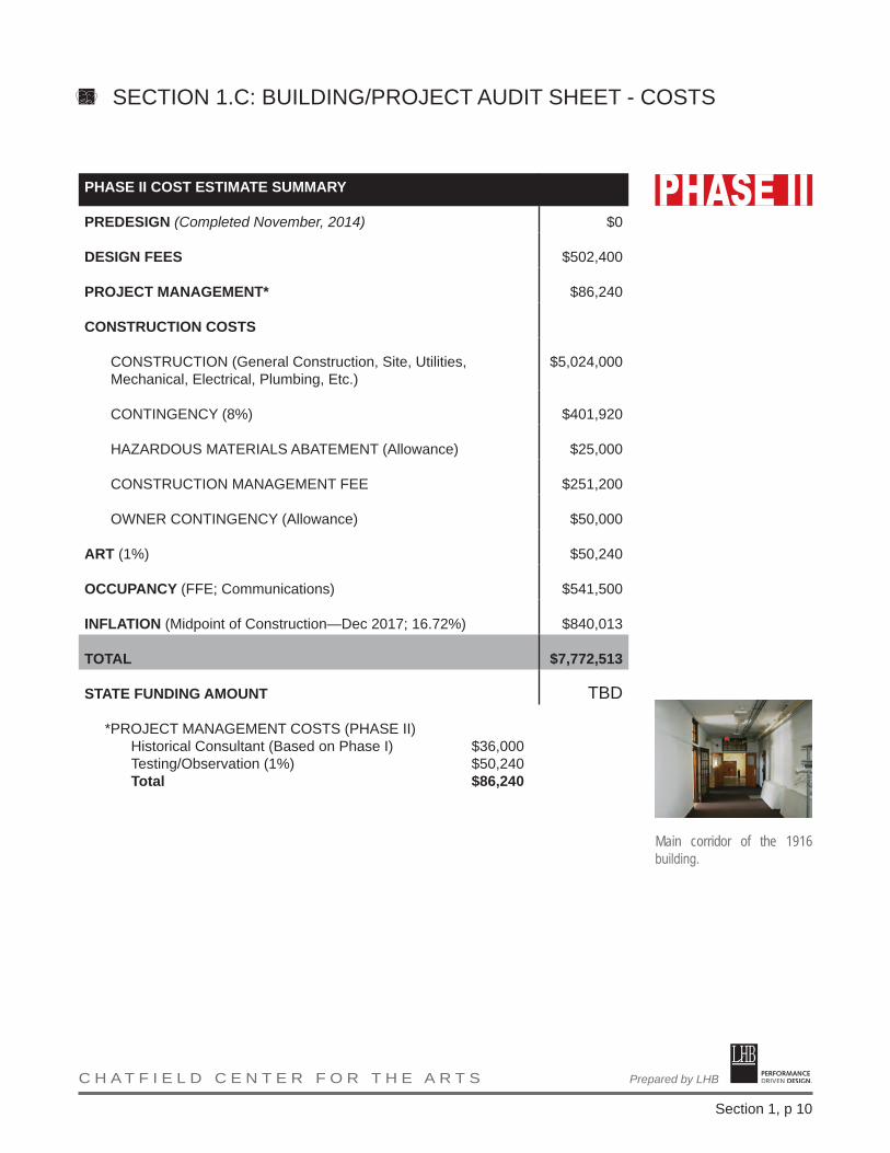
PHASE II COST ESTIMATE SUMMARY
PREDESIGN (Completed November, 2014) $0
DESIGN FEES $502,400
PROJECT MANAGEMENT* $86,240
CONSTRUCTION COSTS
CONSTRUCTION (General Construction, Site, Utilities, Mechanical, Electrical, Plumbing, Etc.)
$5,024,000
CONTINGENCY (8%) $401,920
HAZARDOUS MATERIALS ABATEMENT (Allowance) $25,000
CONSTRUCTION MANAGEMENT FEE $251,200
OWNER CONTINGENCY (Allowance) $50,000
ART (1%) $50,240
OCCUPANCY (FFE; Communications) $541,500
INFLATION (Midpoint of Construction—Dec 2017; 16.72%) $840,013
TOTAL $7,772,513
STATE FUNDING AMOUNT TBD
*PROJECT MANAGEMENT COSTS (PHASE II)Historical Consultant (Based on Phase I) $36,000Testing/Observation (1%) $50,240Total $86,240
SECTION 1.C: BUILDING/PROJECT AUDIT SHEET - COSTS
Main corridor of the 1916 building.

PERFORMANCE DRIVEN DESIGN.Prepared by LHB C H A T F I E L D C E N T E R F O R T H E A R T S
Section 2, p 1
MISSION, STRATEGIC PLAN
MISSIONThe mission is to create a sustainable attraction for culture, education, entertainment, and economic development that will enhance the quality of life for residents in the region while preserving the historical importance of the most prominent, architecturally significant, and well-known building in downtown Chatfield.
EXECUTIVE SUMMARYPotter Auditorium has been an integral part of the heritage in the Chosen Valley for more than 75 years. Potter Auditorium was built in the 1930s during the Great Depression and is now a historic landmark of national significance. Potter needs a re-birth through renovation and modernization so that future generations can enjoy what past generations already have.
The Chatfield community is committed to the preservation and continuance of this still functional building. Conversion and expansion of the current structure into a 21st Century regional arts center, while preserving its historical character, will enhance the enjoyment of the community for residents and visitors alike.
In order to accomplish this, Potter Auditorium will be modernized and retrofitted into a regional, multi-use facility designed to enhance the enjoyment of theatrical and musical presentations in addition to speaker of conferences using the facility.
Regional activities that have been successful in Potter Auditorium, historically, will be continued in a modernized Regional Center for the Arts, include:
• Plays and musicals• Concerts• Museum• Meeting space for senior citizen/community groups• Community events such as weddings and school dances• Areas to display local art work• Space for art shows
GOALSChatfield Center for the Arts will have resonating benefits including nurturing individuals, creating a sustainable community, maintaining a strong regional employee base and enhancing the livability of Southeast Minnesota. Some specific goals include:
• To create a regional arts center that will not only benefit the residents of Chatfield, but Southeast Minnesota as well
• To restore the Potter Auditorium while preserving and enhancing its historical value
• To create space in a regionally central location for community events and gatherings such as theater, music, weddings, concerts, conferences
SECTION 2: BASIS FOR NEED -PROJECT BACKGROUND NARRATIVE

PERFORMANCE DRIVEN DESIGN.Prepared by LHB C H A T F I E L D C E N T E R F O R T H E A R T S
Section 2, p 2
• To create a catalyst for business and economic development in the region• Create a venue capable of hosting productions and crowds of regional
significance• Nurturing individuals, creating a sustainable community, maintaining a
strong regional employee base and enhancing the livability of Southeast Minnesota
VISIONIt is the vision for the Chatfield Center for the Arts to create an elegant, family oriented, live performance venue, art gallery, and conference center in a national historic landmark that will benefit all of southeast Minnesota.
SUMMARY STATEMENT OF HOW PROJECT MEETS NEEDSThe project involves the renovation of Potter Auditorium and the installation of an elevator and elevator-related improvements to serve both the 1936 auditorium building and the 1916 school building. The primary renovation will include seating and amenity improvements within the Potter Auditorium building, improvements to the electrical, plumbing, and HVAC systems throughout the Center for the Arts property.
The installation of an elevator and other accessibility improvements are the only way to make these old buildings accessible to all people. Without those improvements, the use of the buildings would be extremely limited. The seats and most of the amenities in the auditorium date back to 1936, when people were smaller and technology much more limited. Seating improvements will add to the comfort of the patrons while the electrical, plumbing, and HVAC systems are badly needed as improvements to those systems have been limited over the years. The modernization of these systems will provide a sound foundation for these buildings to serve the public well into the future.
OPERATIONAL PROGRAMThe Center is currently operated by the EDA with the assistance of an advisory committee, a local non-profit corporation, and city staff. The City of Chatfield provides a basic level of funding to ensure basic needs are met. The non-profit corporation provides a significant amount of programming and volunteers, which supplements that programming that is generated via private bookings. The Advisory Committee provides oversight of the operations and generates advice to the EDA and the City of Chatfield regarding policy development and programming. It is possible that the EDA will enter into a lease agreement regarding the day to day operations of the Center but the EDA will always maintain ownership.
PROJECT BACKGROUNDIn 2010, the Chatfield Economic Development Authority (EDA) took possession of the 1916 High School Building and a 1935 New Deal auditorium, constructed as an addition to the high school. Since that time, the EDA has actively pursued programming within the buildings, has taken steps to install incremental improvements , and has developed a plan for the continued use of the auditorium and adaptive re-use of the school building. The EDA seeks to preserve and
SECTION 2: BASIS FOR NEED -PROJECT BACKGROUND NARRATIVE

PERFORMANCE DRIVEN DESIGN.Prepared by LHB C H A T F I E L D C E N T E R F O R T H E A R T S
Section 2, p 3
enhance these buildings in such a manner that the historical integrity of the buildings is respected and the practical functionality of the buildings is broadened.
The Chatfield Center for the Arts will have resonating benefits including nurturing individuals, creating a sustainable community, maintaining a strong regional employee base and enhancing the livability of Southeast Minnesota. Some specific goals include:
• To create a regional arts center that will not only benefit the residents of Chatfield, but Southeast Minnesota as well.
• To restore Potter Auditorium while preserving and enhancing its historical value
• To improve accessibility to the buildings, including installation of an elevator.
• To create space in a regionally central location, for community events and gatherings such as theater, music, weddings, concerts, conferences.
• To create a venue capable of hosting productions and crowds of regional significance
• Nurturing individuals, creating a sustainable community, maintaining a strong regional employee base and enhancing the livability of Southeast Minnesota.
PROJECT PLANNINGIn 2007, a steering committee was formed by the school district and the City of Chatfield to establish a strong, shared vision for the project and began gathering the necessary information to create a detailed development plan. An intensive survey and evaluation of the property’s historical and architectural significance was conducted by the city’s historic preservation planner, resulting in a determination of National Register eligibility by the Minnesota State Historic Preservation Office (SHPO) on August 5, 2009.
With the SHPO opinion of National Register eligibility in hand, the stakeholders at the time authorized development of the Preservation Plan, which evolved gradually over the course of several months. Simultaneously, more advanced feasibility studies and initial predesign work was undertaken in anticipation of the 2010 state bonding request.
While State funding was not obtained, the Economic Development Authority issued a Request for Qualifications for Design Services in December of 2010. After an interview process, LHB and their consultants were hired. After a few initial meetings, LHB’s work was put on hold until the project received funding in the 2014 bonding cycle. However, during this time, the Chatfield Center for the Arts Advisory Committee continued to meet and plan for the future.
Once funding was secured, LHB began work on the formal predesign for submission to the City of Chatfield - Economic Development Authority, Department of Employment and Economic Development (DEED), and the Legislature. Multiple meetings were held, both internally within the design team and with the steering
SECTION 2: BASIS FOR NEED -PROJECT BACKGROUND NARRATIVE

PERFORMANCE DRIVEN DESIGN.Prepared by LHB C H A T F I E L D C E N T E R F O R T H E A R T S
Section 2, p 4
committee. The effort involved the following:
LIST OF STAKEHOLDERSCity of ChatfieldChatfield Economic Development AuthorityChatfield Center for the Arts Advisory CommitteeChatfield Center for the Arts, Inc.Wit’s End TheatreChatfield Public Schools
PREDESIGN TEAMSTEERING COMMITTEE
Carmen Narveson, Chatfield Brass Band Chris Giesen, Chatfield EDA F. Mike Tuohy, Chatfield Center for the Arts (CCA), School Board Robert Vogel, Historic Preservation Commission Molly Baum, CCA and EDA Andrew Young, City of Chatfield Joel Young, City of Chatfield Michael Martin, City of Kasson, CCA Matt Opat, CCA Anthony Cole, CCA Damon Prestemon, CCA
Carla Gallina, Gallina Design, LLC Russell Smith, Mayor, CCA Board Joe Chase, Wits End Theatre
Robyn Loewen, Wit’s End TheatreJoan Verdegan, Wit’s End TheatreAllan Dietz, CCA
LHBBruce Cornwall, AIA, Project DesignerSara Phillips, AIA, Project ManagerStuart Shrimpton, Design & Production SupportMelissa White, PE, Civil EngineerLydia Major, PLA, Landscape Architect
DUNHAMSteve Harmon, Associate, MechanicalTony Zaudtke, Senior Associate, Electrical
AUERBACK POLLOCK FRIEDLANDERTom Neville, ASTC, PrincipalEd Babin, Associate
MATTSON MACDONALD YOUNGDavid Macdonald, PE, Structural Engineer
SECTION 2: BASIS FOR NEED -PROJECT BACKGROUND NARRATIVE

PERFORMANCE DRIVEN DESIGN.Prepared by LHB C H A T F I E L D C E N T E R F O R T H E A R T S
Section 2, p 5
PAST REPORTSHistorical information contained in the reports listed below was provided to LHB by the owner and their historical consultant. Copies of the full reports are located in the appendix.
• Chatfield Center for the Arts, Historical, Architectural & Engineering Documentation of the 1916 Gymnasium
• Chatfield Center for the Arts (Also known as the Chatfield High School and Auditorium-Gymnasium Addition), 405 South Main Street, Heritage Landmark Nomination Report
SECTION 2: BASIS FOR NEED -PROJECT BACKGROUND NARRATIVE
PERFORMANCE DRIVEN DESIGN.Prepared by LHB C H A T F I E L D C E N T E R F O R T H E A R T S
Section 2, p 6
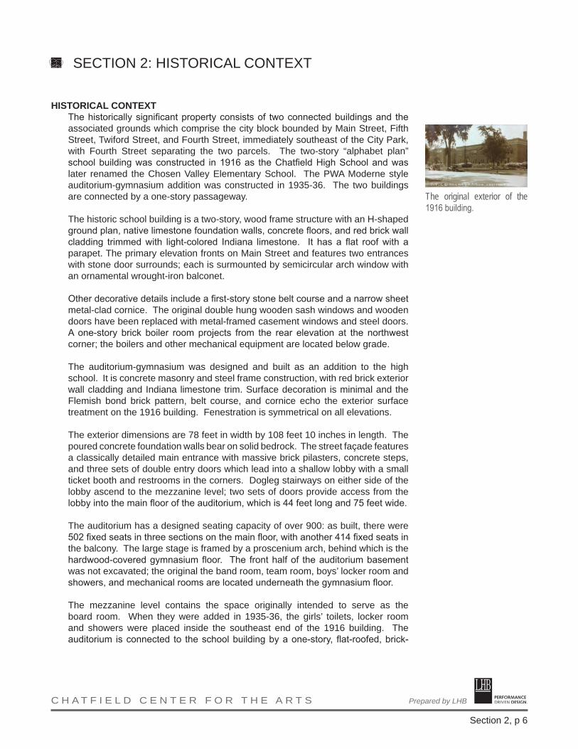
HISTORICAL CONTEXTThe historically significant property consists of two connected buildings and the associated grounds which comprise the city block bounded by Main Street, Fifth Street, Twiford Street, and Fourth Street, immediately southeast of the City Park, with Fourth Street separating the two parcels. The two-story “alphabet plan” school building was constructed in 1916 as the Chatfield High School and was later renamed the Chosen Valley Elementary School. The PWA Moderne style auditorium-gymnasium addition was constructed in 1935-36. The two buildings are connected by a one-story passageway.
The historic school building is a two-story, wood frame structure with an H-shaped ground plan, native limestone foundation walls, concrete floors, and red brick wall cladding trimmed with light-colored Indiana limestone. It has a flat roof with a parapet. The primary elevation fronts on Main Street and features two entrances with stone door surrounds; each is surmounted by semicircular arch window with an ornamental wrought-iron balconet.
Other decorative details include a first-story stone belt course and a narrow sheet metal-clad cornice. The original double hung wooden sash windows and wooden doors have been replaced with metal-framed casement windows and steel doors. A one-story brick boiler room projects from the rear elevation at the northwest corner; the boilers and other mechanical equipment are located below grade.
The auditorium-gymnasium was designed and built as an addition to the high school. It is concrete masonry and steel frame construction, with red brick exterior wall cladding and Indiana limestone trim. Surface decoration is minimal and the Flemish bond brick pattern, belt course, and cornice echo the exterior surface treatment on the 1916 building. Fenestration is symmetrical on all elevations.
The exterior dimensions are 78 feet in width by 108 feet 10 inches in length. The poured concrete foundation walls bear on solid bedrock. The street façade features a classically detailed main entrance with massive brick pilasters, concrete steps, and three sets of double entry doors which lead into a shallow lobby with a small ticket booth and restrooms in the corners. Dogleg stairways on either side of the lobby ascend to the mezzanine level; two sets of doors provide access from the lobby into the main floor of the auditorium, which is 44 feet long and 75 feet wide.
The auditorium has a designed seating capacity of over 900: as built, there were 502 fixed seats in three sections on the main floor, with another 414 fixed seats in the balcony. The large stage is framed by a proscenium arch, behind which is the hardwood-covered gymnasium floor. The front half of the auditorium basement was not excavated; the original the band room, team room, boys’ locker room and showers, and mechanical rooms are located underneath the gymnasium floor. The mezzanine level contains the space originally intended to serve as the board room. When they were added in 1935-36, the girls’ toilets, locker room and showers were placed inside the southeast end of the 1916 building. The auditorium is connected to the school building by a one-story, flat-roofed, brick-
The original exterior of the 1916 building.
SECTION 2: HISTORICAL CONTEXT

PERFORMANCE DRIVEN DESIGN.Prepared by LHB C H A T F I E L D C E N T E R F O R T H E A R T S
Section 2, p 7
walled passageway that spans approximately 22 feet, built concurrently with the auditorium.
While the auditorium is in an excellent state of preservation and virtually unaltered from its original appearance, the façade of the former high school building has lost some of its historic integrity as a result of inappropriate window and door treatments. Successive episodes of interior remodeling have compromised the historic integrity of much of the building’s interior, although considerable historic fabric has survived intact. Some of the school building’s interior structural elements have also deteriorated and parts of the building do not meet current building codes—for example, the wood-framed roof probably does not meet the load-bearing requirements of current building codes and the attic lacks fire separations and smoke enclosures.
Nevertheless, all of the major code deficiencies generally appear to be reversible. More importantly, the architecturally incompatible, two-story brick and concrete elementary classroom wing that was added onto the school building in 1954 was removed in 2010 without causing damage to the exterior of the historic building. However, no restoration of the original facade has occurred.
The 1916 High School and 1936 Auditorium-Gymnasium reflect the evolution of public education as well as the shared cultures and traditions of Chatfield residents. The property offers an excellent perspective for viewing and interpreting the architectural and cultural heritage of Chatfield. For planning purposes, the entire city block is treated as a specific historic environment that visually complements the adjacent town square park and contributes to the historic character of surrounding downtown buildings.
The two historic buildings, each of which is regarded as individually significant in its own right, meet established criteria for historical significance and integrity. Together, they form an irreplaceable community development asset as well as a potent symbol of the town’s commitment to public education and the cultural enrichment of its citizens.
The CCA today: Potter Auditorium in the foreground behind the tree and the 1916 school building beyond.
SECTION 2: HISTORICAL CONTEXT


PERFORMANCE DRIVEN DESIGN.Prepared by LHB C H A T F I E L D C E N T E R F O R T H E A R T S
Section 3, p 1
OPERATIONAL PROGRAMThe Center is currently operated by the EDA with the assistance of an advisory committee, a local non-profit corporation, and city staff. The City of Chatfield provides a basic level of funding to ensure basic needs are met. The non-profit corporation provides a significant amount of programming and volunteers, which supplements that programming that is generated via private bookings. The Advisory Committee provides oversight of the operations and generates advice to the EDA and the City of Chatfield regarding policy development and programming. It is possible that the EDA will enter into a lease agreement regarding the day to day operations of the Center but the EDA will always maintain ownership.
SECTION 3: AGENCY/ORGANIZATION PLANNING

PERFORMANCE DRIVEN DESIGN.Prepared by LHB C H A T F I E L D C E N T E R F O R T H E A R T S
Section 4, p 1
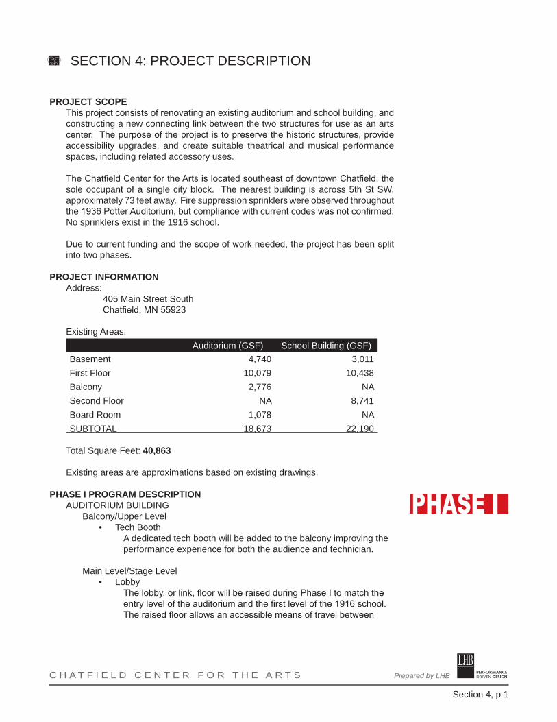
PROJECT SCOPEThis project consists of renovating an existing auditorium and school building, and constructing a new connecting link between the two structures for use as an arts center. The purpose of the project is to preserve the historic structures, provide accessibility upgrades, and create suitable theatrical and musical performance spaces, including related accessory uses. The Chatfield Center for the Arts is located southeast of downtown Chatfield, the sole occupant of a single city block. The nearest building is across 5th St SW, approximately 73 feet away. Fire suppression sprinklers were observed throughout the 1936 Potter Auditorium, but compliance with current codes was not confirmed. No sprinklers exist in the 1916 school.
Due to current funding and the scope of work needed, the project has been split into two phases.
PROJECT INFORMATIONAddress:
405 Main Street SouthChatfield, MN 55923
Existing Areas:Auditorium (GSF) School Building (GSF)
Basement 4,740 3,011First Floor 10,079 10,438Balcony 2,776 NASecond Floor NA 8,741Board Room 1,078 NASUBTOTAL 18,673 22,190
Total Square Feet: 40,863
Existing areas are approximations based on existing drawings.
PHASE I PROGRAM DESCRIPTIONAUDITORIUM BUILDING
Balcony/Upper Level • Tech Booth
A dedicated tech booth will be added to the balcony improving the performance experience for both the audience and technician.
Main Level/Stage Level• Lobby
The lobby, or link, floor will be raised during Phase I to match the entry level of the auditorium and the first level of the 1916 school. The raised floor allows an accessible means of travel between
SECTION 4: PROJECT DESCRIPTION

PERFORMANCE DRIVEN DESIGN.Prepared by LHB C H A T F I E L D C E N T E R F O R T H E A R T S
Section 4, p 2
both buildings.• Main Level Seating
Seating on the main floor of the auditorium to be replaced. New, wheelchair accessible seating to be provided on a new floor, built up over the existing auditorium’s sloped floor in the rear of the auditorium.
• StageThe original stage and gymnasium to be renovated to focus on stage-based performances.
Basement• Mechanical
Existing and newly allocated mechanical space accommodating new air handling units to be renovated.
• Dressing/CostumesSome costume storage and dressing room space to be dedicated as part of the renovation.
• Green RoomA dedicated green room space to become part of the renovated basement, including toilet facilities.
• Dressing RoomA second dressing room to be provided. Each dressing room to have toilet facilities.
1916 BuildingBoth Levels
• ElevatorA new passenger elevator to be added to the 1916 school allowing access to the second floor.
First Level• Restrooms
Existing restrooms will be modified for accessibility, with a complete renovation included in Phase II.
PHASE II PROGRAM DESCRIPTIONAUDITORIUM BUILDING
Balcony/Upper Level• Balcony Seating
Original upper balcony seats to be restored. Lower balcony seats to be replaced.
• Board RoomAn original meeting room to be renovated.
• Connection to linkOver the existing stairway, the catwalk will enter through the existing window opening and provide access to the tech booth as well as connect the balcony to the second floor of the 1916 school building.
Main Level/Stage Level
SECTION 4: PROJECT DESCRIPTION

PERFORMANCE DRIVEN DESIGN.Prepared by LHB C H A T F I E L D C E N T E R F O R T H E A R T S
Section 4, p 3
• Shallow Orchestra PitA shallow orchestra pit to be cut into the floor in front of the stage to improve sight lines and immediate acoustics.
• Loading VestibuleA vestibule added to the existing interior space to temper sound and weather from the loading area.
• Storage MezzanineA mezzanine added to the back of the stage area to store theatrical set pieces, props, etc.
Basement• Vertical connection to link
A new stair to connect between the basement and stage/lobby levels.
NEW LINK/INFILL BUILDINGSecond Level
• Catwalk ConnectionA new, ramped connection between the upper levels of the two buildings.
First Level• Lobby
A new, two story lobby space between the two existing buildings to provide needed gathering space during performances.
• BackstageA portion of the new lobby space accommodating the new stair to the basement below and providing needed offstage space at the stage level.
Basement• Storage
If feasible, create additional storage and support spaces in the basement level of the connecting link. Note that the geotech report indicates exploration should be completed prior to the start of Phase II.
1916 BUILDINGSecond Level
• RestroomsNew restrooms added in Phase II that accommodate guests on the upper levels of both buildings.
• Gathering/ConcessionsAn open area with counter/bar for refreshments during performances/events. The availability of the space on the second level alleviates pressure on the first floor lobby space and accommodates activity in the restored assembly hall.
SECTION 4: PROJECT DESCRIPTION
PERFORMANCE DRIVEN DESIGN.Prepared by LHB C H A T F I E L D C E N T E R F O R T H E A R T S
Section 4, p 4
• StudioRenovated space to accommodate visual arts programs and other activities.
• Conference RoomA large conference room for community meetings and small speaking events/lectures.
• StageA restored element of the original 1916 school.
• Assembly HallA restored element of the original 1916 school.
• Green Room/Off StageSpace adjacent to the restored stage.
• Storage
First Level• Restrooms
Additional restrooms provided to meet code requirements including a unisex, accessible restroom.
• Office• Renovate old gymnasium for small, intimate performances.• Legion Room: for gatherings.• Meeting• Lobby/Concessions
An open area with counter/bar for refreshments during performances/events.
SECTION 4: PROJECT DESCRIPTION

PERFORMANCE DRIVEN DESIGN.Prepared by LHB C H A T F I E L D C E N T E R F O R T H E A R T S
Section 4, p 5
PHASE I PROGRAM MATRIXNOTE: New areas are created within the existing floor plate in Phase I or made possible by the demolition of the existing link in Phase II.Space Size (SF) New Renovate
AUDITORIUM BUILDING Balcony/Upper Level
Board Room 575 XStorage Closets 275 X
Main Level/Stage LevelLobby 365 XMain Level Seating 3,240 XStage 3,900 X
BasementMechanical 1,250 XTheatre Storage 870 XGreen Room 340 X2 Dressing Rooms 310 X
1916 BUILDINGSecond Level
Elevator 80 XFirst Level
Restrooms 690 XElevator 80 X
PHASE II PROGRAM MATRIXSpace Size (SF) New Renovate
AUDITORIUM BUILDING Balcony/Upper Level
Balcony Seating 2,550 XConnection to link 30 XTech Booth 110 X
Main Level/Stage LevelShallow Orchestra Pit 160 XLoading Vestibule 115 XStorage Mezzanine 900 X
BasementVertical connection to link 670 X
SECTION 4: PROJECT DESCRIPTION

PERFORMANCE DRIVEN DESIGN.Prepared by LHB C H A T F I E L D C E N T E R F O R T H E A R T S
Section 4, p 6
Space Size (SF) New RenovateNEW LINK/INFILL BUILDING
Second LevelCatwalk Connection 360 X
First LevelLobby 1,280 XBackstage 300 X
BasementStorage 680 X
1916 BUILDINGSecond Level
Restrooms 690 XGathering/Concessions 550 XStudio 1,215 XConference 670 XStage 550 XAssembly Hall 2,625 XGreen Room/Off Stage 390 XStorage 120 X
First LevelRestrooms 280 XOffice 370 XOld Gymnasium 1,400 XLegion Room 1,215 XMeeting 800 XConcessions 500 X
SECTION 4: PROJECT DESCRIPTION

PERFORMANCE DRIVEN DESIGN.Prepared by LHB C H A T F I E L D C E N T E R F O R T H E A R T S
Section 4, p 7
APPLICABLE CODESNOTE: The codes referenced below are currently in effect. However, the state of Minnesota is slated to adopt a new set of codes in 2015.
2007 Minnesota State Building Code2000 Guidelines for the Rehabilitation of Existing Buildings (GREB) per Minnesota
Rules Chapter 13112006 International Building Code (IBC)
I. MINNESOTA STATE BUILDING CODE
A. Restroom Facilities (1303.1200)Increased ratio for water closets for women to the total of water closets and urinals for men (1303.1200) is covered by requirements set out in Chapter 29 for A-1 and A-3 occupancies.
B. Recycling Space (1303.1500)Space must be provided for the collection, separation, and temporary storage of recyclable materials within or adjacent to all buildings over 1,000 SF.
Space designated for recycling shall be located so it is at least as convenient as the location where other solid waste is collected and must be identified on plans submitted for a building permit.
Use GSF Factor Space RequiredAuditorium 9,853 0.0010 9.85Meeting Rooms 13,303 0.0010 13.30Offices 801 0.0025 2.00Storage 3,029 0.0025 7.57Mechanical 3,029 0.0010 3.03
Total Required Recycling Space 35.76 SF
II. GUIDELINES FOR THE REHABILITATION OF EXISTING BUILDINGS (GREB)
A. Change in Use (502.1.1)Where a change in use is made to a higher hazard area, the heights and area shall meet the limitations of Chapter 5 of IBC. The use of the 1916 school is being changed from an E to A, a higher hazard area per Table 5-A.
B. Historic Structures (Chapter 6)1. Existing door openings, corridor and stairway widths of less than what
is specified elsewhere in these guidelines may be approved, provided that in the opinion of the building official there is sufficient width and height for a person to pass through the opening or transverse the
SECTION 4: APPLICABLE CODES

PERFORMANCE DRIVEN DESIGN.Prepared by LHB C H A T F I E L D C E N T E R F O R T H E A R T S
Section 4, p 8
means of egress.2. Where 1-hour fire-resistant construction is required by these
provisions, it need not be provided, regardless of construction or occupancy, when the existing wall and ceiling finish is wood lath and plaster.
3. Building Area: The allowable floor area for historic buildings undergoing a change in occupancy shall be permitted to exceed the allowable areas specified in Chapter 5 by 20 percent.
4. Accessibility requirements: The accessibility requirements contained in these provisions shall apply to historic buildings undergoing alterations, renovations, reconstruction or a change in occupancy. If the historic character of the building is adversely affected, then alternative provisions for accessibility shall be permitted. However, the accessibility provisions are contained in a portion of GREB that has not been adopted by the State of Minnesota
III. INTERNATIONAL BUILDING CODE (IBC) as modified by State of Minnesota
A. Occupancy Classification (Chapter 3)1. Assembly, A-1 (Theater)2. Assembly, A-3 (Assembly, including community halls and other
assembly uses not classified elsewhere)3. Business, B (Offices)4. Storage, S-1 (Miscellaneous storage areas)
B. Special Requirements (Chapter 4)1. Special provisions apply to stage construction, and dressing/
appurtenant rooms.2. An automatic sprinkler system is required under the roof and gridiron
and under all catwalks and galleries over the stage, dressing rooms, performer lounges, shops, and storerooms accessory to the stage.
C. General Building Heights and Areas (Chapter 5)1. Allowable Areas
a. Existing building plus additions must comply with height and area provisions
b. A-1 is the most restrictive occupancy and non-separated uses are desired, initial review will focus on classifying the entire building as A-1
c. Allowable stories and areas, Table 503: 2 Stories, 8,500 GSF (At)d. Frontage Increase (506.2)
If = [F/P – 0.25]W/30 If = [806/873 – 0.25] 30/30If = 0.67
e. Automatic Sprinkler Increase ((506.3)Is = 0 (Not fully sprinklered)Is = 2 (more than one story above the grade plane)
f. Allowable area per story (506.1), without sprinklers
SECTION 4: APPLICABLE CODES

PERFORMANCE DRIVEN DESIGN.Prepared by LHB C H A T F I E L D C E N T E R F O R T H E A R T S
Section 4, p 9
Aa = {At + [At x If] + [At x Is]}`Aa = {8,500 + [8,500 x 0.67] + [8,500 x 0]Aa = 8,500 + 5695 + 0Aa = 14,195
g. Allowable area per story (506.1), with sprinklersAa = {At + [At x If] + [At x Is]}`Aa = {8,500 + [8,500 x 0.67] + [8,500 x 2]Aa = 8,500 + 5695 + 17,000Aa = 31,195
h. Therefore, the 1916 school shall be sprinklered to avoid fire walls
2. Occupancy Separationsa. No separation required between A-1 and A-3.b. 1 Hour or 2 Hour separation required between A and B Occupancies,
unless B occupancy is accessory (508.3.1) or non-separated occupancies (508.3.2) can be utilized.
c. 1 Hour or 2 Hour separation required between A and S-1 Occupancies, unless B occupancy is accessory (508.3.1) or non-separated occupancies (508.3.2) can be utilized.
d. No separation required between B and S-1.
D. Type of Construction (Chapter 6)1. Assumed Construction Type: III-B.
Existing drawings could not be located for the 1916 school. Drawings for the 1936 auditorium indicate a wood framed roof. All exterior walls appear to be multi-wythe masonry construction
2. Fire Resistive Requirements per Table 601:Structural Frame: 0 hr.Bearing Walls – Exterior 2 hrs.Bearing Walls – Interior 0 hr.Non-Bearing Walls – Exterior 0 hr.Floor Construction 0 hrRoof Construction 0 hr
F. Accessibility (Chapter 11)1. Per Scoping Requirements, existing buildings shall comply with Sections
1112, 1113, and 1114 as found in Minnesota Rules 1341. 2. Technical Infeasible: An alternation of a building or a facility that has
little likelihood of being accomplished because the existing structural conditions require the removal or alteration of a load-bearing member that is an essential part of the structural frame, or because other existing physical or site constraints prohibit modification or addition of elements, spaces, or features, which are in full and strict compliance with the minimum requirements for new construction and which are necessary to provide accessibility.
3. Additions shall be located on an accessible route of travel from an accessible main entrance.
4. Alterations
SECTION 4: APPLICABLE CODES

PERFORMANCE DRIVEN DESIGN.Prepared by LHB C H A T F I E L D C E N T E R F O R T H E A R T S
Section 4, p 10
a. Where existing elements are altered, then each altered element or area shall comply with the applicable provisions for new construction, including provisions requiring an element or area shall be on a common route.
b. If an particular entrance is not made accessible, appropriate accessible signage indicating the location of the nearest accessible entrance shall be installed at or near the inaccessible entrance so that the retracing of the approach route from the inaccessible entrance is not required.
c. The provision limiting the cost of accessibility improvements to the primary function areas of an existing structure do not apply if the alterations are undertaken for the primary purpose of increasing accessibility.
d. Platform (wheelchair) lifts complying with Minnesota Rules 1307 shall be permitted to be used as part of an accessible route.
e. Assembly Areas:a. Wheelchair seating – where it is technically infeasible to alter
all performing areas to be on an accessible route, at least one of each type of performing area shall be made accessible.
b. Dressing, fitting, and locker rooms – Where dressing, fitting, and locker rooms are being altered and technical infeasibility can be demonstrated, one dressing, fitting, or locker room for each sex on each level shall be made accessible.
f. Historic Buildings:a. Entrances: At least one accessible entrance that is used by the
public shall be provided and located on an accessible route.b. Accessible Route: Accessible routes from an accessible
entrance to all publicly used spaces on at least the level of the accessible entrance shall be provided. Access shall be provided to all levels of a building or facility whenever practical.
G. Plumbing Systems (Chapter 29)a. Fixture Count Requirements
Water Closets Lavatories Drinking Fountains
Occupancy Male Female Male FemaleA-1 1 per 125 1 per 65 1 per 200 1 per 500A-3 1 per 125 1 per 65 1 per 200 1 per 500B 1 per 25 for first 50 and
1 per 50 for remainder over 50
1 per 40 for first 80 and 1 per 80 for
remainder over 80
1 per 500
S-1 1 per 100 1 per 100 1 per 1,000
SECTION 4: APPLICABLE CODES

PERFORMANCE DRIVEN DESIGN.Prepared by LHB C H A T F I E L D C E N T E R F O R T H E A R T S
Section 4, p 11
b. Required FixturesWater Closets Lavatories Drinking
FountainsOccupancy Male Female Male Female
A-1 3.50 5.72 2.19 2.19 1.48A-3 4.84 9.30 3.02 3.02 1.37B 1.00 1.00 1.00 1.00 0.01S-1/Mech 0.10 0.10 0.10 0.10 0.02Total Req: 9.44 (10) 16.12 (17) 6.31 (7) 6.31 (7) 2.87 (3)
c. Due to accessibility requirements (1109.2.1), an accessible unisex toilet room shall be provided where an aggregate of six or more male and female water closets is required. The unisex fixtures may be included in determining the number of fixtures provided in an occupancy.
d. Due to accessibility requirements (1109.2.2), where the combined total water closet compartments and urinals provided in a toilet room or bathing facility is six or more, at least one ambulatory-accessible water closet compartment shall be provided in addition to the wheelchair-accessible compartment.
e. Required Fixtures Modifications per State Amendments: a. Water or other beverages available through free or fee-based
serving or dispensers may be substituted for up to 50 percent of the required number of drinking fountains. Therefore only two (2) are required.
b. In each bathroom or toilet room, urinals shall not be substituted for more than 67 percent of the required water closets. Therefore, 6 out of the 10 required men’s water closets may be urinals.
c. When an ambulatory-accessible water closet is required due to six or more male and female water closets in a toilet room, an ambulatory-accessible water closet shall also be provided in the complementary gender specific toilet room.
SECTION 4: APPLICABLE CODES

PERFORMANCE DRIVEN DESIGN.Prepared by LHB C H A T F I E L D C E N T E R F O R T H E A R T S
Section 4, p 12
HISTORICAL CONSIDERATIONSPlanning for the Chatfield Center for the Arts project will focus on preserving historically significant, character defining architectural features. These features represent a combination of design elements and materials that were created during the property’s period of historic significance (1916 to 1959) and therefore constitute the physical links between the past and the present. Because not everything that is old is necessarily worth preserving, preservation treatment strategies emphasize the conservation of specific features which are essential for conveying the property’s significant historical qualities and architectural aspects.
The significant historic character defining features of the 1916 building are its:• Standardized, “alphabet plan” form • Simple rectangular volume, emphasis on the horizontal• Symmetrical, balanced arrangement of windows and doors• Mission Revival-inspired arches and iron balconets above the main
entrances• High proportion of window-to-wall area (designed for daylight and
ventilation)• Interior design reflects arts-and-crafts aesthetic, dependent upon machine-
made effects (mill-work, wood strip floors, wall treatments)
The significant, visually distinctive character defining features of the 1936 building are its:
• Smooth-surfaced, box-like shape• Symmetrical massing and proportions on all four elevations• Extensive use of poured in place concrete• Prominent main entrance with Classical detailing (engaged piers,
entablature)• Continuity of façade details with the 1916 building• Horizontal layering of floors• Interior plan and features reflecting the pattern language of the Moderne
style
The two buildings share the following character defining elements:• Rectilinear building forms• Parapeted roofs• Brown brick exterior walls trimmed with smooth Indiana limestone• Building mass is balanced proportionally with open space
GENERAL STANDARDS FOR PRESERVATION PROJECTSThe National Historic Preservation Act of 1966 makes the Secretary of the Interior responsible for establishing standards for the National Register program. In fulfillment of this responsibility, the National Park Service has developed the Secretary of the Interior’s Standards for the Treatment of Historic Properties. These standards define the general and specific treatments that may be applied to National Register properties, encompassing four general treatment approaches: preservation, rehabilitation, restoration, and reconstruction. The Secretary of the Interior’s Standards for Rehabilitation provide the conceptual underpinnings for
SECTION 4: HISTORICAL CONSIDERATIONS

PERFORMANCE DRIVEN DESIGN.Prepared by LHB C H A T F I E L D C E N T E R F O R T H E A R T S
Section 4, p 13
this preservation plan because the primary objective of the project is to return the 1916 and 1936 buildings to a state of utility through repairs and alterations that make possible an efficient contemporary use while preserving those features of the property which are significant to its historical, architectural, and cultural values.
The following general statements, adapted from the Standards for Rehabilitation, will guide decisions made as part of the design and construction process:
1. All work on historic buildings will be undertaken in accordance with the Secretary of the Interior’s Standards for the Treatment of Historic Properties.
2. Every reasonable effort will be made to provide a compatible use for the 1916 and 1936 buildings that requires minimal alteration of the historic structures and its environment.
3. All work will be designed and executed in a manner that preserves and sustains the distinguishing original qualities and historic character-defining architectural features of the School Building and the Auditorium; no significant historic material or distinctive architectural feature will be removed or altered.
4. The historic property will be recognized as a product of its own time; for planning purposes, its period of historical significance is 1916 to 1959.
5. Changes which have taken place in the course of time will be treated as evidence of the property’s history and development. Although designed and built as an addition to the 1916 School Building, the 1936 Auditorium has acquired significance in its own right and its historical, architectural, and cultural values will be recognized and respected.
6. Distinctive stylistic features and examples of skilled craftsmanship will be treated with sensitivity.
7. Deteriorated architectural features will be repaired rather than replaced, wherever possible. Where replacement is necessary, the new material should match the material being replaced in composition, color, texture, and other visual qualities. Repair or replacement of missing architecture features should be based on accurate duplications of features, substantiated by historical, physical, or pictorial evidence, rather than on conjectural designs or the availability of different architectural elements.
8. The surface cleaning of the 1916 and 1936 buildings will be undertaken with the gentlest means possible. Under no circumstances will sandblasting or other harsh cleaning methods be undertaken that might damage historic building materials.
9. Every reasonable effort will be made to protect and preserve historic landscape resources in Town Square Park which may be affected by
SECTION 4: HISTORICAL CONSIDERATIONS
PERFORMANCE DRIVEN DESIGN.Prepared by LHB C H A T F I E L D C E N T E R F O R T H E A R T S
Section 4, p 14
rehabilitation work on the 1916 and 1936 buildings.
Although they are neither regulatory nor prescriptive, the Secretary of the Interior’s Standards are the required basis for SHPO review and compliance with Section 106 of the National Historic Preservation Act, which would apply if any part of the Chatfield Center for the Performing Arts project were to become a “federal undertaking” due to the use of federal funds.
HISTORICAL TREATMENT RECOMMENDATIONSThis section provides detailed guidance for decisions involving the preservation, protection, and use of the historic property by delineating those important architectural elements which require special protection and recommending specific treatments that are economical but do not sacrifice historic integrity. The recommendations will inform the preparation of detailed construction drawings and other planning documents.
1916 SCHOOL BUILDINGAdaptive use is the only way that the 1916 School Building will be preserved and to be successful, rehabilitation treatments will need to respect and retain the building’s historical significance and architectural integrity, while adding a contemporary layer that provides value for the future. The primary objective is to return the building to a state of utility through repairs and minor alterations that will make possible an efficient new use while preserving those features which are significant to its historical and architectural values.
Structural Systems• Rehabilitation treatments need to recognize the special problems inherent
in the building’s structural systems.
• Adequately treat all known structural problems at the earliest opportunity. Damaged, weakened, or inadequate structural systems should be stabilized and repaired, and replaced only when necessary.
• Minimize the use of heavy machinery that could disturb foundation walls or undermine the structural stability of the building.
Walls• The original brick wall cladding and stone trim should be retained.
• Existing brickwork should be repointed only where there is visible evidence of moisture problems or where mortar is missing; and the old mortar should be duplicated in composition, color, joint profile, and texture.
• Deteriorated or damaged masonry should be repaired; if replacement is necessary, the new brick, stone, or concrete should duplicate the old as closely as possible.
SECTION 4: HISTORICAL CONSIDERATIONS

PERFORMANCE DRIVEN DESIGN.Prepared by LHB C H A T F I E L D C E N T E R F O R T H E A R T S
Section 4, p 15
• The original metal cornice should be retained. Where necessary, deteriorated or missing material should be repaired or replace in-kind.
Roof• If may be necessary to modify the shape and material of the existing light-
frame truss roof. The new roof should not be visible from the street. See related information in the structural portion of this report.
• The parapet walls contribute to the building’s architectural character and should be preserved intact.
• The original skylights should be restored. Installation of new skylights is appropriate, provided they are not visible from the street.
Windows and Doors• The location and size of existing window and door openings need be
retained.
• The existing window sash is inappropriate and should be replaced with custom wood double-hung sash that replicate the original windows in design, material, and hardware.
• New storm windows and screens should be visually unobtrusive.
• The wrought-iron balconets and arched window surrounds above the entrances (facing Main Street) are important to the property’s historic integrity and should be retained.
• New doors should duplicate the design, materials, and hardware of the originals.
Exterior Finishes• Clean masonry walls only when necessary to halt deterioration or to
remove stains. Always use the gentlest means possible, such as low pressure water and scrubbing and rising using soft natural bristle brushes. The use of chemical cleaning products is generally not recommended.
• Historic masonry exposed by demolition of the 1954 classroom wing should be cleaned using hand tools, with masonry patched, and windows reinstalled.
• Cleaning of the cornice should use appropriate architectural metals cleaning substances and methods that will not abrade the surface or alter the color of the original sheet metal.
SECTION 4: HISTORICAL CONSIDERATIONS
PERFORMANCE DRIVEN DESIGN.Prepared by LHB C H A T F I E L D C E N T E R F O R T H E A R T S
Section 4, p 16
Interior Features & Finishes• Retain as much original material as possible.
• Remove dropped ceilings.
• Avoid installing new decorative treatments which use historically inappropriate materials, such as vinyl, plastic or imitation wood paneling or flooring (except in utility areas).
• Repair damaged or deteriorated lath and plaster walls and ceilings, wooden moldings, wood paneling, and terrazzo floors, replacing damaged or deteriorated material with new material that duplicates the old as closely as possible.
• Demolition of non-load bearing walls and partitions is an appropriate rehabilitation treatment.
• Restore the historic skylights; new skylights would be appropriate for public rooms.
• Replace the wood floors removed as part of the 2009 asbestos abatement program with new hardwood flooring (preferably from trees cut and milled in southeastern Minnesota).
• Whenever possible, use native species for new woodwork, including doorways, windows, baseboards, and moldings.
• Discover the original paint colors, finishes and other decorative finishes.
• Remove paint from wood trim that was painted over. When treating unpainted woodwork, complete stripping may not be necessary for removing damaged or deteriorated finishes.
Garage• The existing garage (currently used for storage) on the back of the building
is not a historic structure; it distracts from the property’s historic character and therefore should not be retained.
1936 AUDITORIUMAdaptive use of the 1936 Auditorium should have minimal impact on the building’s architectural integrity. However, to ensure that its historic fabric will be properly cared for, while making better use of the building itself, renovation will need to apply measures that preserve intact the existing form, integrity, and materials of the building’s exterior. There will need to be minor alterations to some interior spaces in order to make the auditorium more efficient.
SECTION 4: HISTORICAL CONSIDERATIONS

PERFORMANCE DRIVEN DESIGN.Prepared by LHB C H A T F I E L D C E N T E R F O R T H E A R T S
Section 4, p 17
Walls• The original brick, stone, and concrete masonry and mortar should be
retained.
• Brickwork should be repointed only where there is visible evidence of moisture problems or where mortar is missing; and the old mortar should be duplicated in composition, color, joint profile, and texture.
• Deteriorated or damaged masonry should be repaired. If replacement is necessary, the new brick, stone, or concrete should duplicate the old as closely as possible.
• The original metal cornice should be retained. Wherever necessary, deteriorated or missing material should be repaired or replaced in-kind.
Roof• The original roof shape should be preserved and the original roof material
should be retained.
• The parapet walls contribute to the building’s architectural character and should be preserved intact.
Windows and Doors• The location and size of existing window and door openings will need to be
retained.
• The existing windows are not appropriate and should be replaced with custom windows that duplicate the design and material of the originals.
• New storm windows and screens should be visually unobtrusive.
• New main entry doors should duplicate the design, material, and hardware of the originals.
Entrances• The classical detailing and concrete steps leading to the main entrance
should be retained intact.
Exterior Finishes• Clean masonry walls only when necessary to halt deterioration or to
remove stains. Always use the gentlest means possible, such as low pressure water and scrubbing and rising using soft natural bristle brushes. The use of chemical cleaning products is generally not recommended.
• Cleaning of the cornice should use appropriate architectural metals cleaning substances and methods that will not abrade the surface or alter the color of the original sheet metal
SECTION 4: HISTORICAL CONSIDERATIONS

PERFORMANCE DRIVEN DESIGN.Prepared by LHB C H A T F I E L D C E N T E R F O R T H E A R T S
Section 4, p 18
Interior Features & Finishes• Retain all of the historically significant, character-defining interior features
of the auditorium including the main floor and balcony seating areas, the proscenium stage, lobby, and mezzanine-level board room.
• Preserve as much as possible of the 1936 floor plan, the spatial relationship and size of the rooms, corridors, and other aspects of the original design.
• Retain as much original material, architectural features, and hardware as possible and avoid installing new decorative material that is historically inappropriate, such as vinyl or imitation wood paneling (except in utility areas).
• Repair damaged or deteriorated walls, ceilings and floors, replacing damaged or deteriorated material with new material that duplicates the old as closely as possible.
• Restore the Board Room to recover the decorative details as it appeared at a specific point in time during the property’s period of historical significance (1936-1959).
• Discover the original paint colors and decorative finishes in public areas.
SECTION 4: HISTORICAL CONSIDERATIONS

PERFORMANCE DRIVEN DESIGN.Prepared by LHB C H A T F I E L D C E N T E R F O R T H E A R T S
Section 4, p 19
PROPOSED MECHANICAL SYSTEMS
PRIMARY HEATING
1. Install new high-efficiency condensing boilers and circulating pumps to provide low-temperature (140F to 150F) heating water.a. Install boilers in Phase I within the existing 1916 Building mechanical
area, to serve the Auditorium Building through new buried supply and return piping.
b. Retain existing 90 HP steam boiler for primary heating in the 1916 Building until future Phase II work is performed. In the future, both buildings would be heated with low temperature hot water via new supply and return piping.
c. Install two boiler modules in Phase I, with space for installation of additional module(s) in Phase II.
d. Coordinate with Owner and Gas Utility to determine whether retaining the existing buried fuel oil storage tank and installing dual-fuel burners provides sufficient savings (through lower gas rates based on an “interruptible” gas service) to justify the added cost of the dual-fuel burners and related fuel oil piping.
e. Demo existing steam and condensate piping, and replace with new insulated steel heating water piping according to relevant phase. (Conversion to hot water heating would occur in the Potter Auditorium building as part of Phase I, with conversion of the 1916 Building in the future as part of Phase II.)
f. Reasons for conversion from steam to low-temperature water heat include:i. Safety concerns of exposed radiator temperatures using steam,ii. Unknown (but assumed poor) condition of 100 year-old steam and
condensate piping,iii. Increased efficiency available from modern condensing boilers.
2. Radiators:a. For Phase I (Potter Auditorium renovation), replace heating elements
within existing sidewall convectors to deliver equivalent heat while retaining existing appearance. Reuse existing free-standing radiators in entry lobby and board room if suitable for use with hot water, or replace with historic-type radiators as necessary. Increase total surface area with matching radiators as required.
b. For Phase II (1916 School Building), reuse existing panel radiators where installed and replace covered fin-tube elements with appropriate historic-type hot water radiators sized for sufficient capacity using low-temperature water based on reduced heat load resulting from window upgrades.
c. For 1916 School Building operation (on steam) prior to Phase II construction, install protective guards or enclosures around existing exposed radiator surfaces for burn prevention. Design of enclosures to be coordinated with space aesthetics and historic preservation requirements.
SECTION 4: MECHANICAL CONSIDERATIONS
Phases noted throughout section.

PERFORMANCE DRIVEN DESIGN.Prepared by LHB C H A T F I E L D C E N T E R F O R T H E A R T S
Section 4, p 20
VENTILATION & AIR CONDITIONING
1. Potter Auditorium (Phase I)a. Demo existing 1937 air-handling unit below stage, and replace with
modern equipment to supply heating, cooling and ventilation to the main seating area and balcony.i. Supply air through existing high-level openings at either side of the
stage and (if required for increased flow and/or throw at low velocity) through additional supply openings above the stage.
ii. New system to use low-temperature heating water and DX cooling, with minimum MERV-8 filtration and ventilation rates per code.
iii. Reuse existing concept of removing air volume required for ventilation from the back of the auditorium and balcony, with new fans(s) and possible reuse of existing exhaust ductwork. Include variable-rate ventilation control based on space occupancy.
b. Install a second new air-handling unit in a new basement mechanical space to condition and ventilate the basement-level remodeled support spaces and backstage areas at the first level.i. New supply and return air ductwork.ii. Low-temperature heating water and DX cooling, with minimum MERV-
8 filtration and ventilation rates per code. VAV equipment and operation.
c. Install new fan-coil unit(s) with remote condenser(s) to ventilate and cool the Board Room space.
d. For new toilet rooms created within the 1916 Building to serve the Auditorium as part of Phase I, provide ducted exhaust to a new roof-mounted toilet exhaust fan in compliance with code requirements.
e. General:i. Air-handling equipment, ductwork, and supply/return openings serving
the auditorium, balcony and backstage areas shall be designed for low-velocity and low-noise operation, in conjunction with the project’s theater consultant and best practice for performance spaces.
ii. Mechanical equipment, ductwork and piping in areas adjacent to the auditorium, below the stage or on the roof of the building shall be designed and installed to minimize noise and transmission of vibration into the performance space.
2. 1916 Building (Phase II)a. The Predesign concept proposal is for heating the building using low-
temperature hot water as described above, with space cooling and ventilation as follows:i. Replace existing basement air-handling unit with new equipment for
distribution of conditioned outdoor air to each room through existing ventilation supply and return ductwork. Supply air from outdoors would be tempered with low-temperature hot water heat, DX cooling and minimum MERV-8 filtration.
ii. Install new ductwork to connect existing return/relief ductwork to the air-handling unit, or consider supplying (and exhausting) only the
SECTION 4: MECHANICAL CONSIDERATIONS
Phases noted throughout section.
PERFORMANCE DRIVEN DESIGN.Prepared by LHB C H A T F I E L D C E N T E R F O R T H E A R T S
Section 4, p 21
amount required for ventilation of spaces. In this case, consider heat recovery from the exhaust airstream to the intake air.
iii. Install cooling-only fan-coil units to serve individual spaces, connected to a variable-flow refrigerant condensing unit located on the roof of the 1916 Boiler Room. Space is available in the existing attic for units to serve second floor rooms directly from above. First floor spaces could be served by similar units located in existing closets or new small mechanical spaces, or located in the attic with ductwork to the conditioned spaces through the existing duct shafts in corridor walls.
b. The existing Catering Kitchen has limited exhaust provisions, and this should be upgraded as the kitchen space is revised or upgraded.
c. Toilet Rooms: As noted above, any new toilet rooms installed in Phase I should have exhaust ducted to the roof when constructed. Additional toilet rooms added or revised in Phase II should also be ducted to the roof in accordance with code-required air volumes.
AUTOMATIC CONTROLS
1. Demo existing pneumatic controllers, piping and actuators throughout, as areas are renovated.
2. Install a new DDC control system for new and existing equipment in Phase I, with capacity for future expansion to serve Phase II.
3. Include control of individual space temperatures with new room temperature sensors and hot water control valves for radiators.
PLUMBING
1. Water service at building entry to be upgraded with new piping, meter and backflow prevention (Phase I)
2. New piping to be installed throughout the Auditorium Building in Phase I to serve all plumbing fixtures, and new domestic cold water, hot water and hot water recirc piping from the 1916 Boiler Room area to the Auditorium Building through buried conduits in conjunction with new heating water connections.
3. New gas-fired water heaters in the 1916 Building basement to serve Phase A areas and sized with capacity to serve projected Phase II areas in the future. Include new hot water recirculating pump and piping.
4. Evaluate existing sewage pumps in sump at Auditorium basement mechanical room for possible replacement (depending on age of pumps and controller, which appear to be relatively new).
5. Evaluate existing rainwater piping from Auditorium Building (Phase I) and from 1916 Building (Phase II) to determine whether current code capacities are met. Upgrades to rainwater piping sizes and separation of stormwater drainage from sanitary sewer are assumed for both buildings.
SECTION 4: MECHANICAL CONSIDERATIONS
Phases noted throughout section.
PERFORMANCE DRIVEN DESIGN.Prepared by LHB C H A T F I E L D C E N T E R F O R T H E A R T S
Section 4, p 22
FIRE PROTECTION
1. Fire Protection water service at building entry to be upgraded with backflow prevention in Phase I work.
2. Phase I: Existing sprinkler heads in Auditorium Building to be revised as required to match new room arrangements, and piping and heads to be added in the basement areas (which do not presently include sprinkler coverage).
3. Phase II: Full sprinkler coverage with piping and heads to be added throughout the 1916 Building, served from existing 4” service and zone valve.
SECTION 4: MECHANICAL CONSIDERATIONS
PERFORMANCE DRIVEN DESIGN.Prepared by LHB C H A T F I E L D C E N T E R F O R T H E A R T S
Section 4, p 23
PROPOSED ELECTRICAL SYSTEMS
GENERAL
1. The remodel of the building will occur in phases. Work in each area of the building will be associated with the phases indicated below, unless noted otherwise. a. Phase I – Work associated with the building exterior and the auditorium. b. Phase II – Work associated with the 1916 building.
DEMOLITION
1. Demolish entire electrical distribution system.2. Demolish electrical fixtures, devices, and associated wiring and raceways in
phases as the building is remodeled in phases.
ELECTRICAL SERVICE (PHASE I)
1. Coordinate with Xcel Energy to provide new utility transformer. 2. Provide a 1000-amp, 277/480V, 3-phase, 4-wire service entrance rated
switchboard for the building in the 1916 building on main level or second floor.
POWER
1. Phase I and Phase II as portions of the building are remodeled. 2. Lighting and power panelboards shall be dead front, bolt-on circuit breaker
type 77/480V and 120/208V panelboards shall be distributed throughout the building to provide distributed power to the building.
3. A separate, insulated ground wire shall be provided for all branch circuit and distribution wiring and shall be installed in a metallic raceway. The ground wire shall connect the ground bus of each panelboard to the main facility ground bus.
4. All 120V and 277V circuits shall include dedicated neutrals.5. All home-run circuits shall be in ¾” conduit, minimum.6. MC cable shall be allowed for concealed branch circuit wiring within walls and
above accessible ceilings, homeruns shall be in conduit. 7. Provide stainless steel cover plates on all devices.8. All receptacles mounted in a vertical fashion shall have the ground pin on top.
Unless noted otherwise, no more than 6 duplex receptacles shall be circuited to any single circuit breaker.
9. Space is being allocated on each level for electrical rooms. Panelboards located in electrical rooms or unfinished spaces shall be surface mounted.
10. Wall mounted receptacles shall be recessed at 18” or 48” above finished floor, and 6” above counters.
11. Provide 120V power connection to all power door openers.
SECTION 4: ELECTRICAL CONSIDERATIONS

PERFORMANCE DRIVEN DESIGN.Prepared by LHB C H A T F I E L D C E N T E R F O R T H E A R T S
Section 4, p 24
12. Mechanical loads ½ horse-power and greater will be connected to 277/480V panelboards. General lighting circuits will be 277V, 1-phase.
13. See mechanical narrative for feeders and related electrical equipment to service mechanical equipment. a. Power shall be provided to all heating, ventilation and air conditioning
equipment, and to equipment provided by the owner and/or other contractors. The power source shall be appropriate for the equipment application (i.e. normal , standby, and emergency) and shall be properly labeled at the power source. Fused disconnects with the properly sized overcurrent protection shall be provided where needed.
b. Install VFD’s furnished by the Mechanical Contractor.c. 120V connections to unit heaters shall be provided.d. Provide connections for rooftop mounted exhaust fans. Refer to
mechanical narrative for further exhaust fan information.e. Motor starters, disconnects, contactors, start/stop pushbutton stations
and other control devices shall be provided based on the application requirements where not provided as an integral part of the equipment.
f. Power feeders for motors, heating equipment and permanently installed appliances shall have a separate insulated ground wire, properly connected, to effectively ground the equipment’s metal frames and enclosures.
LIGHTING SYSTEMS
1. Phase I and Phase II as portions of the building are remodeled. 2. Interior and Exterior illumination shall be by a combination of energy efficient,
T-8 and “PL” compact fluorescent lamps with electronic ballasts and LED fixtures with electronic drivers.
3. Lighting Design: Illumination levels shall be in accordance with current design practices, but shall not be less than the minimum levels prescribed by the Illuminating Engineering Society (IES). The lighting design shall also meet the lighting power density (LPD) requirements of ASHRAE 90.1 using the whole building method.
4. Lighting circuits will be connected to a combination of local controls and connection to a programmable network lighting control system to provide a variety of control methods. a. Any public areas shall be connected to network lighting control system,
network lighting control system head end provided in Phase I. 5. All occupancy sensors shall include auxiliary contact for communication to
building automation system. They will be dual technology type and fluorescent ballasts to be program start.
6. Refer to architectural narrative for details on decorative lighting.7. Refer to the theatre narrative for details on theatre lighting, house lighting, and
controls.
SECTION 4: ELECTRICAL CONSIDERATIONS

PERFORMANCE DRIVEN DESIGN.Prepared by LHB C H A T F I E L D C E N T E R F O R T H E A R T S
Section 4, p 25
SIGNAL SYSTEMS
1. Phase I and Phase II as portions of the building are remodeled. 2. Provide new telecommunications closet within each building.
a. Telecommunications closets shall be located to provide EIA/TIA maximum horizontal cabling distances of 100 meters.
3. Provide a ground bar located in each Data and electrical room connected to the Electrical Service ground via #4 AWG grounding conductor.
4. Provide rough-in for low voltage telecommunications and AV cabling.5. Provide new addressable fire alarm system throughout entire building with
intelligible audible notification.
SECTION 4: ELECTRICAL CONSIDERATIONS

PERFORMANCE DRIVEN DESIGN.Prepared by LHB C H A T F I E L D C E N T E R F O R T H E A R T S
Section 4, p 26
DESIGN PHASE GEOTECHNICAL EVALUATION
SUMMARY OF RESULTS
At the surface, the soil borings in the grass areas on the north and east sides of the existing buildings encountered about ½ to 1½ feet of topsoil, while the borings in the parking areas on the west side met approximately 2 to 3½ inches of asphalt over 4 to 8 inches of aggregate base or sand sub-base.
Beneath the topsoil and pavements, all of the borings encountered dark, clayey fill to depths of 5½ to 7 feet. The fill consisted primarily of sandy clay and clayey sand, mixed with some brick debris in areas.
Except for the two borings closest to the building, the fill was underlain by residual soils. At most locations, this material consisted of medium to dense clayey silt with dolostone fragments (residual dolostone). On the north side of the building, the residual material was a reddish clay.
All of the borings encountered harder, more intact rock at depths ranging from about 6 to 7 feet below the surface. In the two borings closest to the building, this material appeared to be present directly below the fill. In the other borings, the change was more of a transition between the residual soils and the weathered rock. The harder, weathered rock materials were mostly dolostone or a combination of dolostone and sandstone.
The borings met auger refusal at depths of 8 to12 feet on materials judged to be fresher, intact dolostone bedrock.
Free water was not encountered in any of the soil borings during our exploration and none of the samples returned appeared to have excess moisture. Due to the nature of the underlying rock materials, infiltrating water would be expected to seep vertically and horizontally through and along fractures or more porous zones of the rock.
SUMMARY OF ANALYSIS
As mentioned, the borings encountered clayey fill materials to depths of about 5½ to 7 feet. Most of the fill was rather dark and appears to be spoil or green area fill that was not intended for structural support. The geotechnical engineer recommends removing all fill from below the area of the addition, along with any topsoil, asphalt, and aggregate base materials or other unsuitable materials. Structural fill supporting the existing foundations can reasonably remain in place.
Depending on the depth of the existing building foundation, depth of soil correction, and the proposed addition foundation elevation, sheeting or shoring may be needed to provide lateral stability to the existing foundations. The existing structure has a lower level in some areas that appears to correspond to the depth of the fill materials observed.
SECTION 4: GEOTECHNICAL EVALUATION

PERFORMANCE DRIVEN DESIGN.Prepared by LHB C H A T F I E L D C E N T E R F O R T H E A R T S
Section 4, p 27
With the understood foundation loads and implementation of the earthwork recommendations, we are of the opinion that foundations may be designed to exert bearing pressures up to 3,000 psf.
The site is considered to be in an “active” karst environment and infiltrating structures is discouraged in this environment. Potential sources for ponding water should be adequately lined.
SECTION 4: GEOTECHNICAL EVALUATION

PERFORMANCE DRIVEN DESIGN.Prepared by LHB C H A T F I E L D C E N T E R F O R T H E A R T S
Section 4, p 28
GENERAL STRUCTURAL REQUIRMENTS FOR A NEW ELEVATOR (PHASE I)
New Elevators• A new elevator can be constructed within the existing 1916 and another
in the 1936 building. The new elevator walls shall be 8” block masonry and shall be built tight to the underside of the existing floor and roof structures. The new masonry walls will act as bearing support for the existing structure when the new elevator opening is cut. A pit is likely required that extends 4’ below the lowest floor level. Some minor underpinning of existing walls adjacent to the pit may be required. The pit foundation walls shall be 12” block masonry. The pit floor shall be a 4” slab on grade. The pit slab will be thickened under the anchor points for the elevator rails.
Built-up Floor• A lightweight concrete floor can be built-up over a portion of the
auditorium floor. A lightweight concrete topping of 3 ½” is placed over built-up rigid insulation to create needed elevations.
GENERAL STRUCTURAL REQUIREMENTS FOR THE LINK/INFILL (PHASE II)
Roof Construction• The roof will be constructed using 1 ½” – 20 ga or stronger metal deck
supported by open web steel bar joists. The deck will span in the north to south direction.
• The roof deck will be supported by 18” deep open web bar joists spaced approximately 4’-0” on center spanning the east to west direction. The bar joists will bear within pockets cut into the exterior bearing wall of the Auditorium building.
○ An expansion joint will be developed at the intersection of the new roof with the School building. If possible, a ledger beam will be connected to the existing exterior wall of the school building which will provide a bearing surface for the new bar joists. The bar joists will be connected to the ledger with slotted bolted connections allowing for slight differential movements between the structures.
○ If it is found that the attachment of a ledger to the existing wall is difficult, risky or not feasible, an independent beam supported by two to three new tube columns, placed 1” clear of the face of the existing wall, will be added to support the joist ends.
• Roof joists will be designed to accommodate hangers that extend down to carry the proposed catwalk that connects the upper level of the school building to the upper level of the auditorium.
○ Hangers will likely be constructed using 3” or 4” diameter pipe columns.
○ It is possible that hanger loads will exceed the capacity of reasonable sized bar joists, in which case a structural steel wide flange beam will be used in lieu of the bar joist at selected locations.
SECTION 4: GENERAL STRUCTURAL REQUIREMENTS

PERFORMANCE DRIVEN DESIGN.Prepared by LHB C H A T F I E L D C E N T E R F O R T H E A R T S
Section 4, p 29
• Figure-1 illustrates the likely roof construction.
Catwalk Construction.• The catwalk will be constructed using composite metal deck with
concrete topping. The total thickness of deck and topping is likely to be 4”.
• The deck and topping will be supported by 6” structural steel channels spaced approximately 2’-6” to 3’ -0” on center and will span between the
SECTION 4: GENERAL STRUCTURAL REQUIREMENTS
Figure-1: Schematic Roof Framing of the Link/Infill (Phase II)

PERFORMANCE DRIVEN DESIGN.Prepared by LHB C H A T F I E L D C E N T E R F O R T H E A R T S
Section 4, p 30
Figure-2: Schematic Catwalk Framing (Phase II)
edge beams on each side of the catwalk.• The edge beams will be 15” deep channels that extend 4” above the
level of the catwalk floor to form a “kick plate”. The top flange of the channel will provide a surface for attachment of the railing system.
• The outside edge of the catwalk, the side of each catwalk that is adjacent to the existing building wall, will likely be constructed also with a 15 deep channel and supported from the roof structure above with pipe hangers. The location of existing window openings and the fenestration of the brick veneer for each building will make connection of the catwalk directly to the existing building wall difficult or not feasible.
• Figure-2 illustrates the likely catwalk construction.
SECTION 4: GENERAL STRUCTURAL REQUIREMENTS
PERFORMANCE DRIVEN DESIGN.Prepared by LHB C H A T F I E L D C E N T E R F O R T H E A R T S
Section 4, p 31
First Floor Framing• The first floor will be constructed using a 4” thick poured concrete slab on
grade.• The first floor slab over the partial basement area of the auditorium will
be incorporated as part of the first floor area.• It is likely that a new stair will be constructed for access to the basement
area. ○ The new stair will be constructed with 12” steel channel stringers
and light gauge steel riser and treads. The tread pans will be filled with concrete.
New Exterior Walls• The new south wall of the link will likely be curtainwall with a significant
portion of the wall containing glass. ○ The structure supporting the wall will be structural steel beams
located at the roof and upper floor level supported by two steel tube columns.
• The new north and east wall at the rear of the link may be constructed with load bearing block masonry. The masonry is likely to be 8” thick with grouted, reinforced lintel block over window and door openings. The block masonry will likely require vertical reinforcing spaced approximately 48” on center.
• It appears that the new south and east walls are intended to align over the existing basement foundation walls.
Building Foundations• Foundation walls will be constructed using 8” thick block masonry or
poured concrete. ○ The foundation walls may need to be thicker depending on the
finish material applied to the wall above grade. For example, if the wall were to be covered with a brick veneer separated from the block backup by a 4” cavity, the
○ foundation wall will be 16” thick. ○ Foundation walls will extend to frost depth where required. ○ Foundation walls should be stepped downward to approximately
match the top of footing elevation of the Auditorium building which appear to be lower than normal frost depth in some locations
• It appears that underpinning of the School building foundations will be required.
• The new first floor level of the link is likely lower than the bottom of the existing footings at the school building.
○ Underpinning is a tedious and labor intensive procedure. But done properly will provide a solid stable foundation for the existing building.
○ Excavation will take place under short sections of the existing footing. The length of wall to be excavated is limited to an amount that can temporarily span the open excavation for a
SECTION 4: GENERAL STRUCTURAL REQUIREMENTS

PERFORMANCE DRIVEN DESIGN.Prepared by LHB C H A T F I E L D C E N T E R F O R T H E A R T S
Section 4, p 32
short period of time. ○ New footings and foundation walls are constructed under each
short section of excavated wall to re-establish direct bearing on the soil surface below.
○ After the new footing concrete and wall have cured for 3 to 7 days the next adjacent length of wall is excavated to repeat the underpinning process.
○ Sections of wall can be excavated simultaneously to complete the underpinning process in a “checkerboard” pattern.
○ Figure-3 and Figure-4 illustrate the typical underpinning method. • Footings will be poured concrete with mild steel reinforcing. It is assumed
at this time that the existing soil and subgrade conditions will allow the design of normal spread footings.
Figure-3: Suggested Underpinning Procedures (Phase II)
Figure-4: Typical Underpinning Section (Phase II)
SECTION 4: GENERAL STRUCTURAL REQUIREMENTS
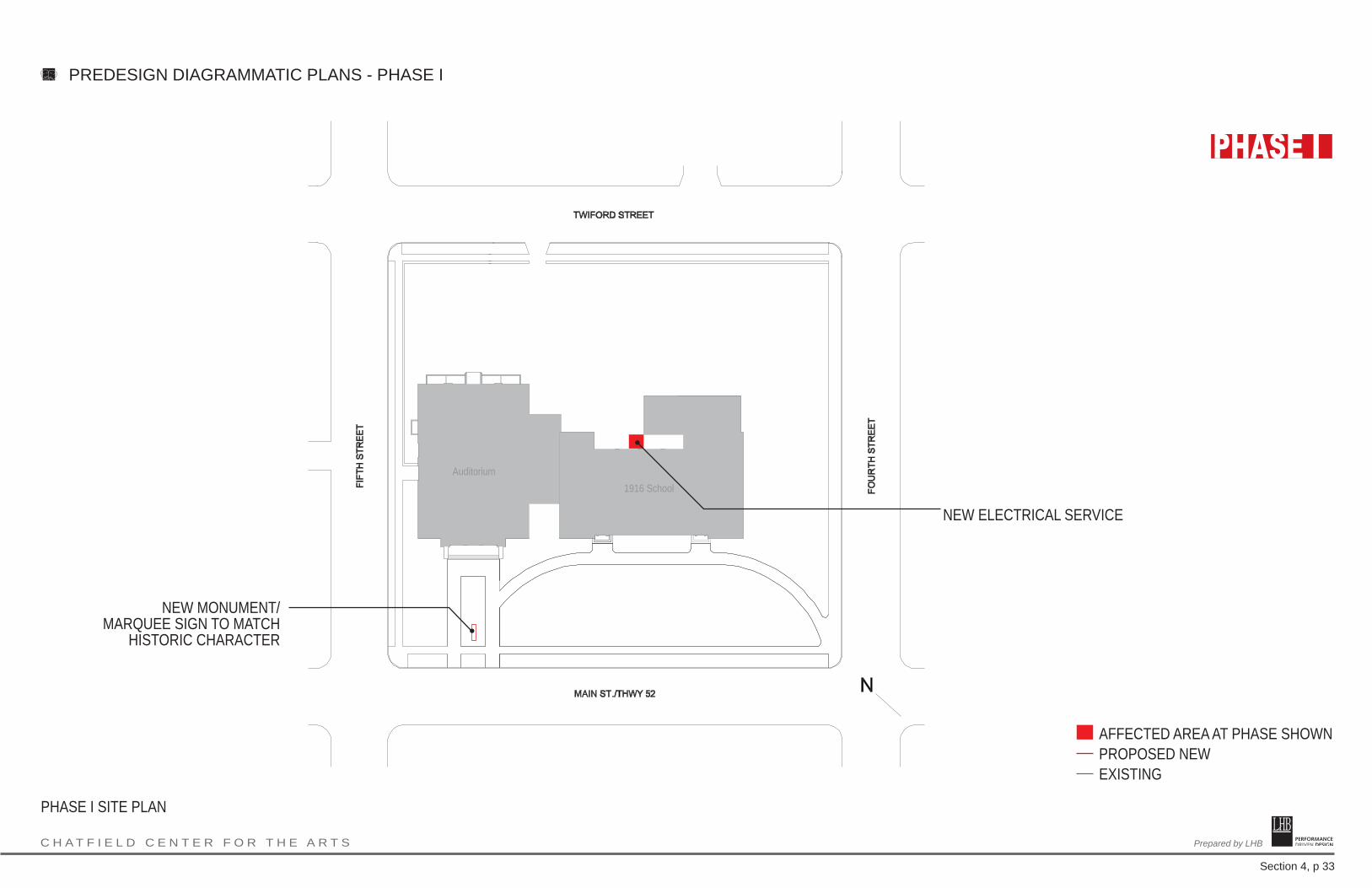
C H A T F I E L D C E N T E R F O R T H E A R T S PERFORMANCE DRIVEN DESIGN.Prepared by LHB
Section 4, p 33
PREDESIGN DIAGRAMMATIC PLANS - PHASE I
AFFECTED AREA AT PHASE SHOWNPROPOSED NEWEXISTING
PHASE I SITE PLAN
NEW MONUMENT/MARQUEE SIGN TO MATCH
HISTORIC CHARACTER
NEW ELECTRICAL SERVICE
Auditorium1916 School

PERFORMANCE DRIVEN DESIGN.Prepared by LHB C H A T F I E L D C E N T E R F O R T H E A R T S
Section 4, p 34
PREDESIGN DIAGRAMMATIC PLANS - PHASE I
AFFECTED AREA AT PHASE SHOWNPROPOSED NEWEXISTING
MECHANICAL W/ NEW AHU
ADDITIONAL MECHANICAL W/NEW BOILERS
PHASE I BASEMENT PLAN
DRESSING/COSTUMES
NEW STAIR
EXIT
DRESSING
DRESSING/GREEN ROOMLARGE PASSENGER ELEVATOR
NEW ELECTRICAL SERVICE
REPLACE STEAM BOILERS WITH NEW HOT WATER BOILERS
NEW HOT WATER SUPPLY AND RETURN LINES
Mechanical
NEW WHEELCHAIR ACCESSIBLE SEATING
NEW SEATS
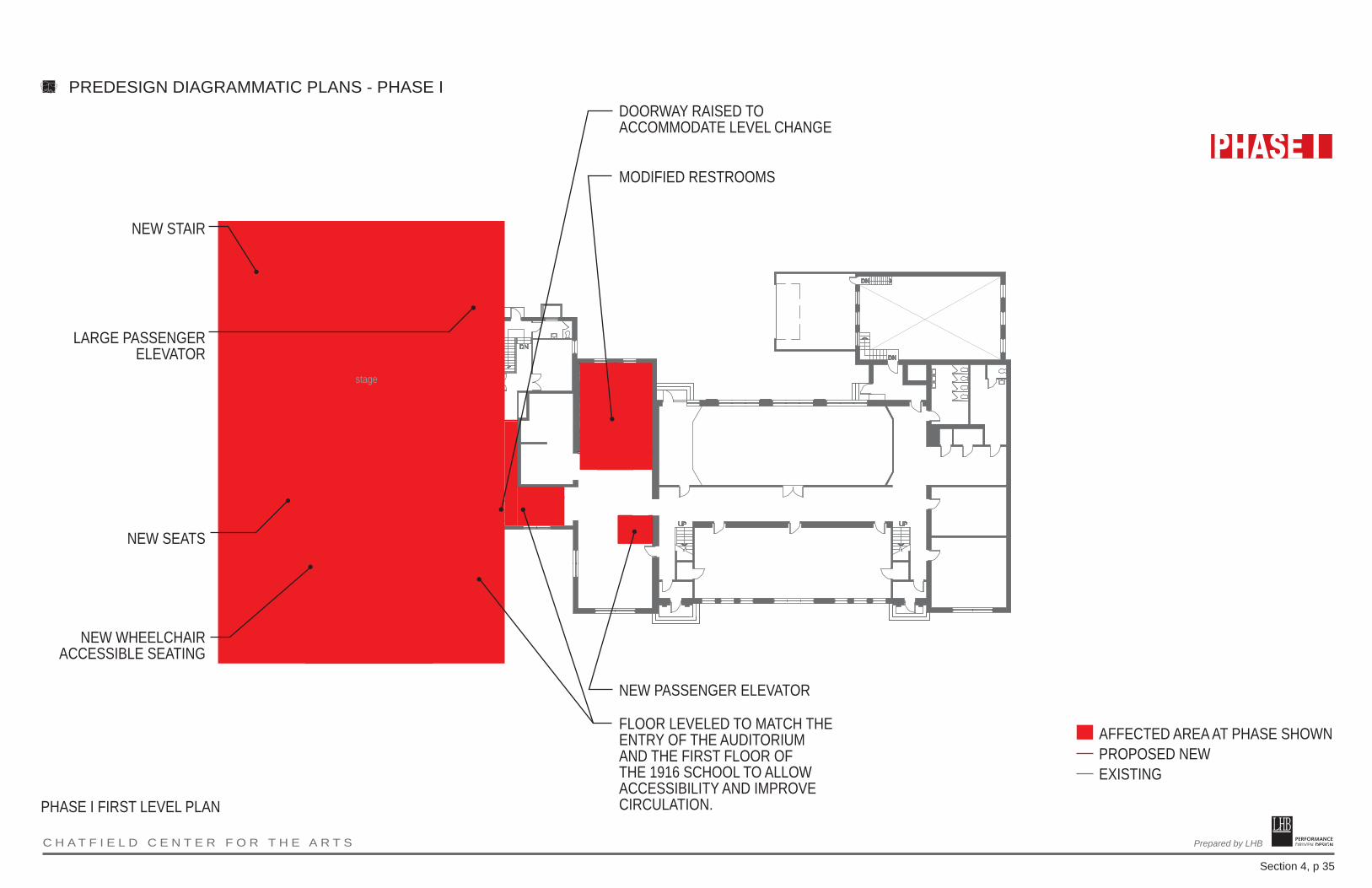
PERFORMANCE DRIVEN DESIGN.Prepared by LHB C H A T F I E L D C E N T E R F O R T H E A R T S
Section 4, p 35
PREDESIGN DIAGRAMMATIC PLANS - PHASE I
AFFECTED AREA AT PHASE SHOWNPROPOSED NEWEXISTING
PHASE I FIRST LEVEL PLAN
FLOOR LEVELED TO MATCH THE ENTRY OF THE AUDITORIUM AND THE FIRST FLOOR OF THE 1916 SCHOOL TO ALLOW ACCESSIBILITY AND IMPROVE CIRCULATION.
NEW PASSENGER ELEVATOR
NEW WHEELCHAIR ACCESSIBLE SEATING
DOORWAY RAISED TO ACCOMMODATE LEVEL CHANGE
MODIFIED RESTROOMS
NEW STAIR
NEW SEATS
LARGE PASSENGER ELEVATOR
stage

PERFORMANCE DRIVEN DESIGN.Prepared by LHB C H A T F I E L D C E N T E R F O R T H E A R T S
Section 4, p 36
PREDESIGN DIAGRAMMATIC PLANS - PHASE I
AFFECTED AREA AT PHASE SHOWNPROPOSED NEWEXISTING
PHASE I BOARD ROOM/SECOND LEVEL PLAN
NEW PASSENGER ELEVATORNEW TECH BOOTH
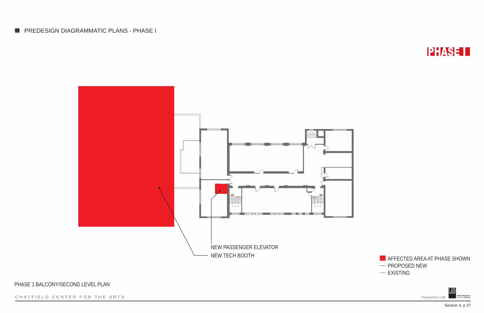
PERFORMANCE DRIVEN DESIGN.Prepared by LHB C H A T F I E L D C E N T E R F O R T H E A R T S
Section 4, p 37
PREDESIGN DIAGRAMMATIC PLANS - PHASE I
AFFECTED AREA AT PHASE SHOWNPROPOSED NEWEXISTING
PHASE 1 BALCONY/SECOND LEVEL PLAN
NEW PASSENGER ELEVATORNEW TECH BOOTH

PERFORMANCE DRIVEN DESIGN.Prepared by LHB C H A T F I E L D C E N T E R F O R T H E A R T S
Section 4, p 38
PREDESIGN DIAGRAMMATIC PLANS - PHASE I
AFFECTED AREA AT PHASE SHOWNPROPOSED NEWEXISTING
PHASE 1 SECTION THROUGH AUDITORIUM
FLOOR RAISED TO MATCH LEVEL AT AUDITORIUM ENTRY AND TO PROVIDE SAME-LEVEL ACCESS FROM 1916 FIRST FLOOR (SEE PLANS)
NEW TECHNICAL CONTROL BOOTH
EXISTING DOORWAY RAISED UP TO ACCOMMODATE LEVELLING OF FLOOR

PERFORMANCE DRIVEN DESIGN.Prepared by LHB C H A T F I E L D C E N T E R F O R T H E A R T S
Section 4, p 39
PREDESIGN EXTERIORS - PHASE I
1. REPLACE WINDOWS2. REPLACE DOORS
NOTE: ADDITIONAL IMPROVEMENTS AND REPAIRS ARE INCLUDED IN PHASE II
1
2
AUDITORIUM MAIN STREET ELEVATION

PERFORMANCE DRIVEN DESIGN.Prepared by LHB C H A T F I E L D C E N T E R F O R T H E A R T S
Section 4, p 40
PREDESIGN EXTERIORS - PHASE I
1. REPLACE WINDOWS2. REPLACE DOORS
NOTE: ADDITIONAL IMPROVEMENTS AND REPAIRS ARE INCLUDED IN PHASE II
1
2
AUDITORIUM FIFTH STREET ELEVATION

PERFORMANCE DRIVEN DESIGN.Prepared by LHB C H A T F I E L D C E N T E R F O R T H E A R T S
Section 4, p 41
PREDESIGN EXTERIORS - PHASE I
1. REPLACE WINDOWS2. REPLACE DOORS
NOTE: ADDITIONAL IMPROVEMENTS AND REPAIRS ARE INCLUDED IN PHASE II
1
2
AUDITORIUM PARKING LOT ELEVATION

PERFORMANCE DRIVEN DESIGN.Prepared by LHB C H A T F I E L D C E N T E R F O R T H E A R T S
Section 4, p 42
PREDESIGN EXTERIORS PLANS - PHASE I
1. REPLACE WINDOWS
NOTE: ADDITIONAL IMPROVEMENTS AND REPAIRS ARE INCLUDED IN PHASE II
1
AUDITORIUM NORTH ELEVATION (TOWARD 1916 SCHOOL BUILDING)

PERFORMANCE DRIVEN DESIGN.Prepared by LHB C H A T F I E L D C E N T E R F O R T H E A R T S
Section 4, p 43
PREDESIGN DIAGRAMMATIC PLANS - PHASE II
AFFECTED AREA AT PHASE SHOWNPROPOSED NEWEXISTINGPHASE I
PHASE II SITE PLAN
NEW DROP-OFF ZONE @ ACCESSIBLE ENTRANCE
TRUCK TURN-AROUND
MAIN ENTRANCE
NEW LINK /INFILL SPACESERVICE ENTRY
NEW PARKING LOT
NEW SIGNAGE
NEW SIGNAGE
NEW SIDEWALKS
NEW LANDSCAPING APPROPRIATE TO HISTORIC LANDSCAPE TREATMENT
NEW SIDEWALK
Auditorium1916 School
REPAIR HISTORIC STEPS
NEW LANDSCAPE GARDEN
CAST PARKING LOT/LOADING LOT
NEW LOADING CANOPY & RAISED DOCK

PERFORMANCE DRIVEN DESIGN.Prepared by LHB C H A T F I E L D C E N T E R F O R T H E A R T S
Section 4, p 44
PREDESIGN DIAGRAMMATIC PLANS - PHASE II
AFFECTED AREA AT PHASE SHOWNPROPOSED NEWEXISTINGPHASE I
PHASE II BASEMENT PLAN
NEW STAIR
STORAGE
SHALLOW ORCHESTRA PIT W/ LIFT

PERFORMANCE DRIVEN DESIGN.Prepared by LHB C H A T F I E L D C E N T E R F O R T H E A R T S
Section 4, p 45
PREDESIGN DIAGRAMMATIC PLANS - PHASE II
AFFECTED AREA AT PHASE SHOWNPROPOSED NEWEXISTINGPHASE I
PHASE II FIRST LEVEL PLAN
NEW ACCESSIBLE ENTRY FROM PARKING LOT
NEW RESTROOMS INCLUDING 1 UNISEX, ACCESSIBLE RESTROOM
NEW STAIR
LIGHT AND SOUND DAMPENING ENTRIES
TO AUDITORIUM(SECOND ENTRY
ADDED TO INCREASE EASE OF MOVEMENT
BETWEEN SPACES)
MAIN ENTRANCE
LOBBY/CONCESSIONS AREA
Lobby
Backstage
Meeting
Office
Legion Room
Old Gymnasium
Open to Mechanical
Below
SHALLOW ORCHESTRA PIT W/LIFT
STORAGE MEZZANINE
LOADING VESTIBULE
MODIFIED RESTROOMS
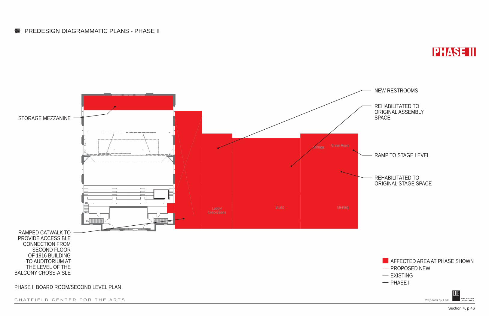
PERFORMANCE DRIVEN DESIGN.Prepared by LHB C H A T F I E L D C E N T E R F O R T H E A R T S
Section 4, p 46
PREDESIGN DIAGRAMMATIC PLANS - PHASE II
AFFECTED AREA AT PHASE SHOWNPROPOSED NEWEXISTINGPHASE I
PHASE II BOARD ROOM/SECOND LEVEL PLAN
RAMPED CATWALK TO PROVIDE ACCESSIBLE
CONNECTION FROM SECOND FLOOR
OF 1916 BUILDING TO AUDITORIUM AT THE LEVEL OF THE
BALCONY CROSS-AISLE
NEW RESTROOMS
REHABILITATED TO ORIGINAL ASSEMBLY SPACE
RAMP TO STAGE LEVEL
REHABILITATED TO ORIGINAL STAGE SPACE
Lobby/Concessions
Studio Meeting
Green RoomStorage
STORAGE MEZZANINE
NEW SEATS

PERFORMANCE DRIVEN DESIGN.Prepared by LHB C H A T F I E L D C E N T E R F O R T H E A R T S
Section 4, p 47
PREDESIGN DIAGRAMMATIC PLANS - PHASE II
AFFECTED AREA AT PHASE SHOWNPROPOSED NEWEXISTINGPHASE I
PHASE II BALCONY/SECOND LEVEL PLAN
RAMPED CATWALK TO PROVIDE ACCESSIBLE CONNECTION FROM SECOND FLOOR OF 1916 BUILDING TO AUDITORIUM AT THE LEVEL OF THE BALCONY CROSS-AISLE
NEW RESTROOMS
REHABILITATED TO ORIGINAL ASSEMBLY SPACE
RAMP TO STAGE LEVEL
REHABILITATED TO ORIGINAL STAGE SPACE
Lobby/Concessions
StudioMeeting
Green RoomStorage
NEW SEATS
NEW WHEELCHAIR ACCESSIBLE SEATING
STORAGE MEZZANINE
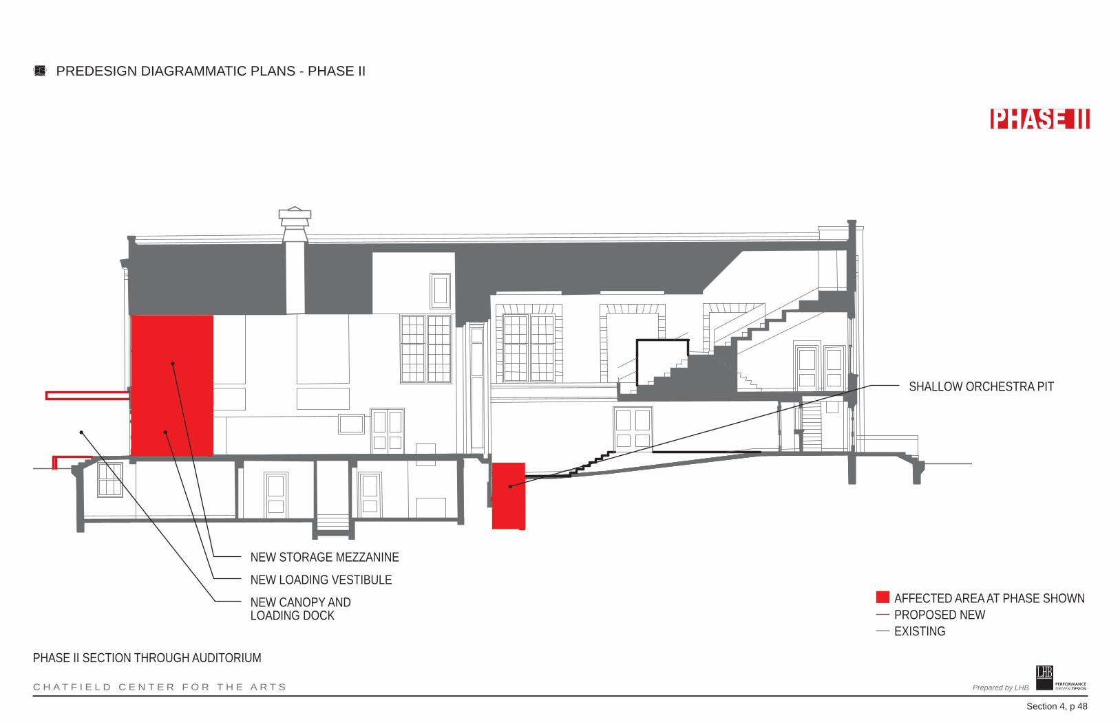
PERFORMANCE DRIVEN DESIGN.Prepared by LHB C H A T F I E L D C E N T E R F O R T H E A R T S
Section 4, p 48
PREDESIGN DIAGRAMMATIC PLANS - PHASE II
AFFECTED AREA AT PHASE SHOWNPROPOSED NEWEXISTING
PHASE II SECTION THROUGH AUDITORIUM
NEW LOADING VESTIBULE
NEW STORAGE MEZZANINE
SHALLOW ORCHESTRA PIT
NEW CANOPY AND LOADING DOCK
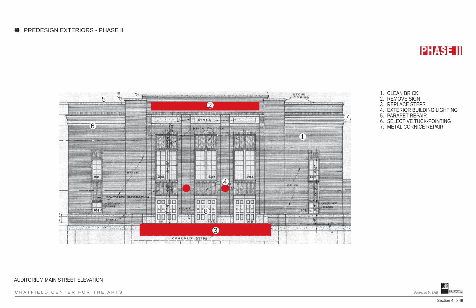
PERFORMANCE DRIVEN DESIGN.Prepared by LHB C H A T F I E L D C E N T E R F O R T H E A R T S
Section 4, p 49
PREDESIGN EXTERIORS - PHASE II
1. CLEAN BRICK2. REMOVE SIGN3. REPLACE STEPS4. EXTERIOR BUILDING LIGHTING5. PARAPET REPAIR6. SELECTIVE TUCK-POINTING7. METAL CORNICE REPAIR
1
2
7
3
4
5
6
8
AUDITORIUM MAIN STREET ELEVATION
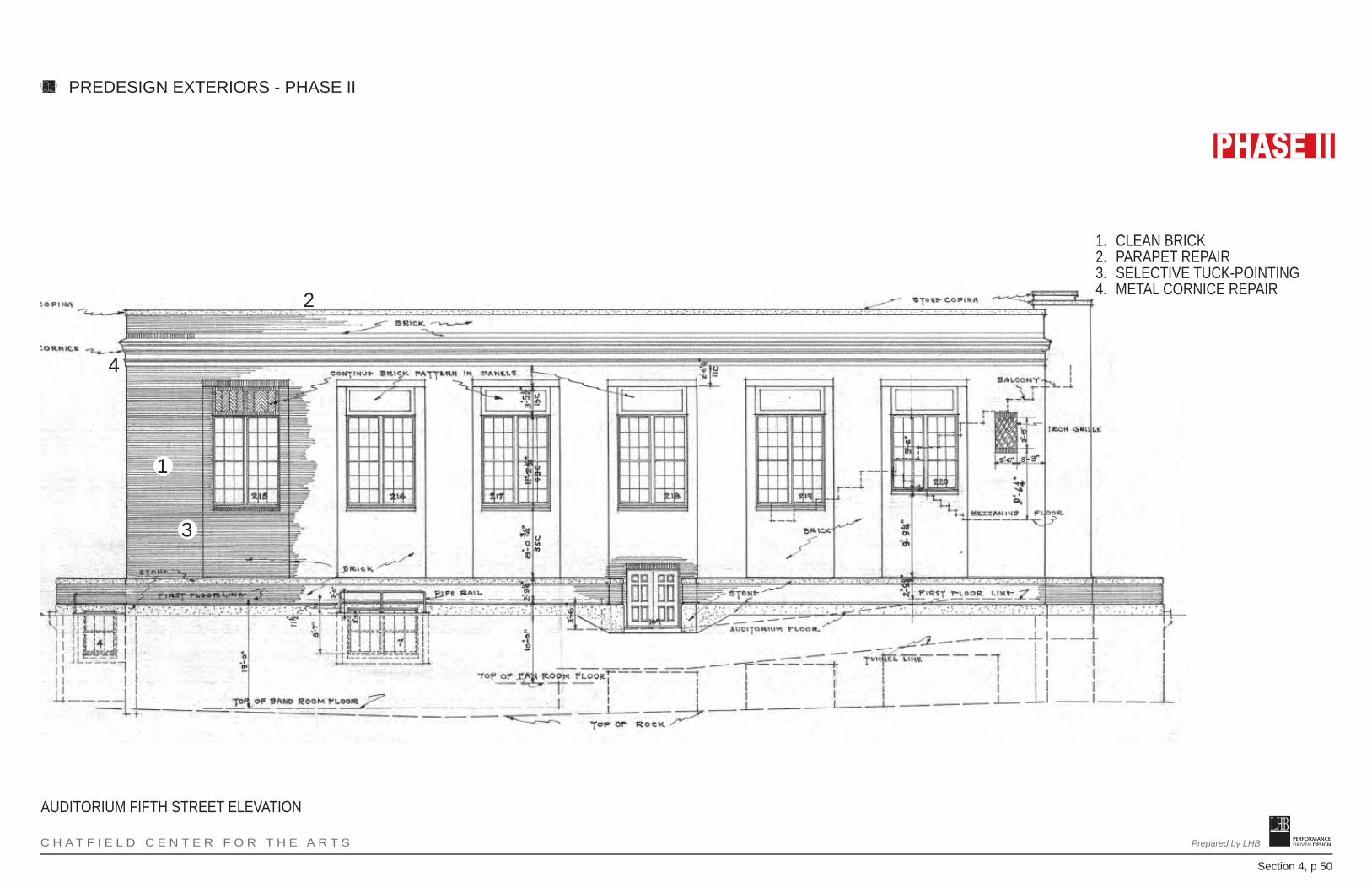
PERFORMANCE DRIVEN DESIGN.Prepared by LHB C H A T F I E L D C E N T E R F O R T H E A R T S
Section 4, p 50
PREDESIGN EXTERIORS - PHASE II
1. CLEAN BRICK2. PARAPET REPAIR3. SELECTIVE TUCK-POINTING4. METAL CORNICE REPAIR
1
2
4
3
AUDITORIUM FIFTH STREET ELEVATION

PERFORMANCE DRIVEN DESIGN.Prepared by LHB C H A T F I E L D C E N T E R F O R T H E A R T S
Section 4, p 51
PREDESIGN EXTERIORS - PHASE II
1. CLEAN BRICK2. REPLACE STEPS3. PARAPET REPAIR4. SELECTIVE TUCK-POINTING5. METAL CORNICE REPAIR6. CANOPY (NEW)
1
3
4
5
6
2
AUDITORIUM PARKING LOT ELEVATION

PERFORMANCE DRIVEN DESIGN.Prepared by LHB C H A T F I E L D C E N T E R F O R T H E A R T S
Section 4, p 52
PREDESIGN EXTERIORS PLANS - PHASE II
5
1. CLEAN BRICK2. PARAPET REPAIR3. SELECTIVE TUCK-POINTING4. METAL CORNICE REPAIR5. DEMOLITION AND
REPLACEMENT OF CONNECTING LINK
1
3
4
2
AUDITORIUM NORTH ELEVATION (TOWARD 1916 SCHOOL BUILDING)

PERFORMANCE DRIVEN DESIGN.Prepared by LHB C H A T F I E L D C E N T E R F O R T H E A R T S
Section 4, p 53
PREDESIGN EXTERIORS - PHASE II
1. CLEAN BRICK2. REPLACE WINDOWS3. PARAPET REPAIR4. SELECTIVE TUCK-POINTING5. REPLACE DOORS
1
3
4
5
2
1916 SCHOOL BUILDING MAIN STREET ELEVATION
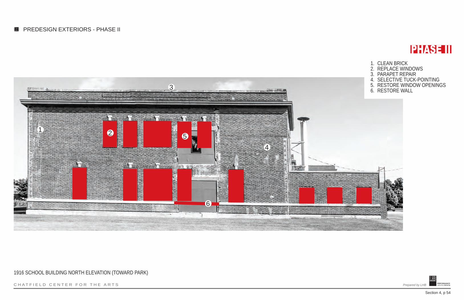
PERFORMANCE DRIVEN DESIGN.Prepared by LHB C H A T F I E L D C E N T E R F O R T H E A R T S
Section 4, p 54
PREDESIGN EXTERIORS - PHASE II
1. CLEAN BRICK2. REPLACE WINDOWS3. PARAPET REPAIR4. SELECTIVE TUCK-POINTING5. RESTORE WINDOW OPENINGS6. RESTORE WALL
1
3
45
6
2
1916 SCHOOL BUILDING NORTH ELEVATION (TOWARD PARK)
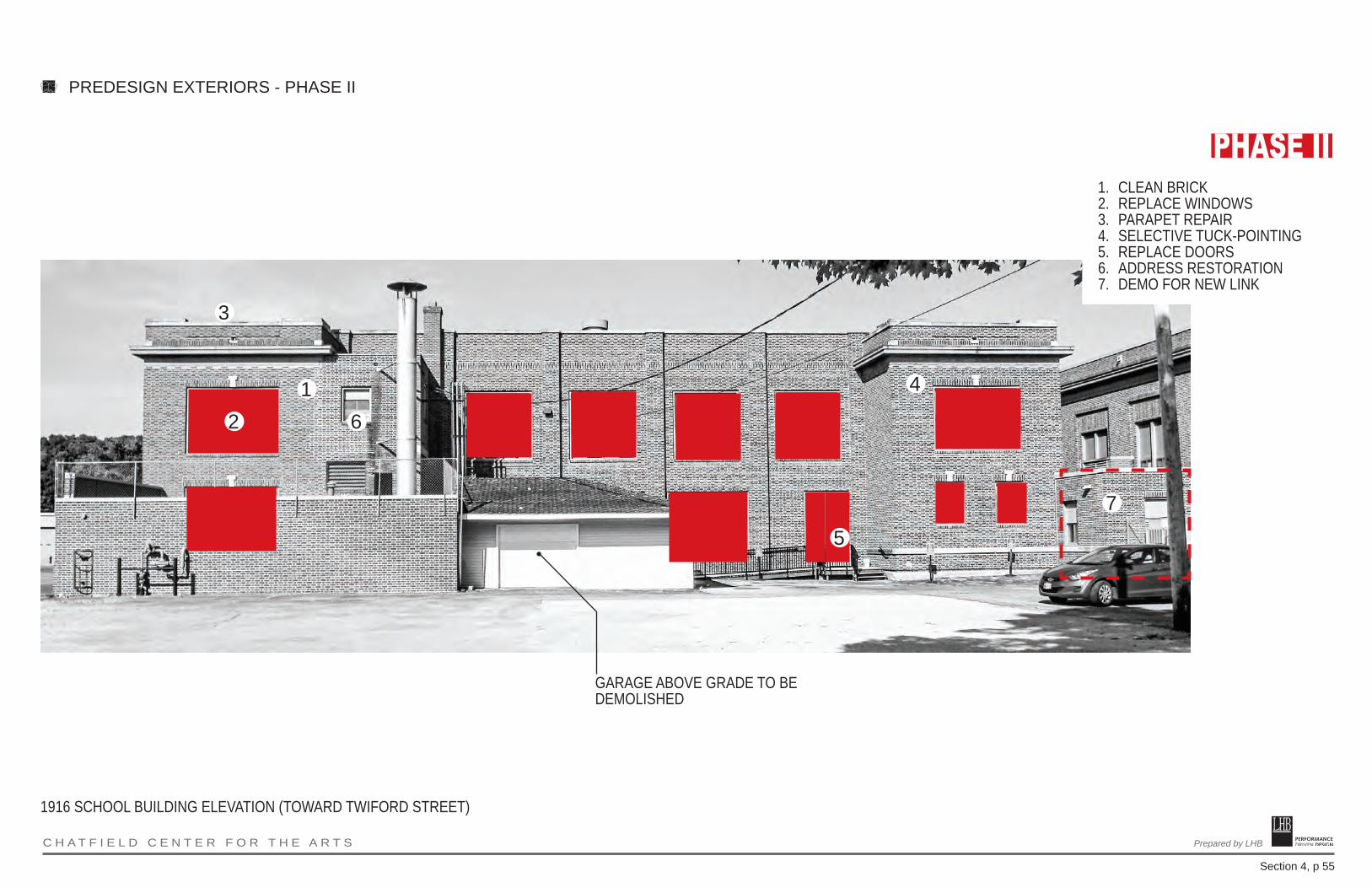
PERFORMANCE DRIVEN DESIGN.Prepared by LHB C H A T F I E L D C E N T E R F O R T H E A R T S
Section 4, p 55
PREDESIGN EXTERIORS - PHASE II
1. CLEAN BRICK2. REPLACE WINDOWS3. PARAPET REPAIR4. SELECTIVE TUCK-POINTING5. REPLACE DOORS6. ADDRESS RESTORATION7. DEMO FOR NEW LINK
GARAGE ABOVE GRADE TO BE DEMOLISHED
16
3
4
5
7
2
1916 SCHOOL BUILDING ELEVATION (TOWARD TWIFORD STREET)

PERFORMANCE DRIVEN DESIGN.Prepared by LHB C H A T F I E L D C E N T E R F O R T H E A R T S
Section 4, p 56
PREDESIGN EXTERIORS - PHASE II
1. CLEAN BRICK2. REPLACE WINDOWS3. PARAPET REPAIR4. SELECTIVE TUCK-POINTING5. DEMO FOR NEW LINK
1
3
4
5
2
1916 SCHOOL BUILDING SOUTH ELEVATION (TOWARD AUDITORIUM)

PERFORMANCE DRIVEN DESIGN.Prepared by LHB C H A T F I E L D C E N T E R F O R T H E A R T S
Section 4, p 57
STATUTORY REQUIREMENTS
The following statutory requirements related to sustainability or energy useapply:
• Minnesota Statute 16B.32: Energy Use. Statute addresses the use of alternative energy sources, on site energy generation from renewable sources, and energy conservation goals.
• Minnesota Statute 16B.325: Sustainable Building Guidelines. Statute focuses on achieving the lowest possible lifetime costs and creating and maintaining a healthy environment for new buildings and major renovations. Note: only projects funded through General Obligation Bonds are required by law to comply with the Sustainable Building Guidelines.
• Minnesota Statute 16B.326: Heating and Cooling Systems; State-Funded Buildings. Use of geothermal and solar thermal heating and cooling where practicable.
• Minnesota Statute 16B.327: Recycling Construction and Demolition Waste from State Buildings. Divert from a landfill ll and recycle at least 50% of nonhazardous construction and demolition waste.
• Minnesota Statute 216B.241, Subdivision 9: Building Performance Standards - Sustainable Building 2030.
ENERGY CONSUMPTION
New construction areas will be designed to meet the SB2030 standards, as required by current State law.
RENEWABLE ENERGY
In order to reduce the impact on the environment, reduce the carbon footprint, and meet the requirements of Minnesota State Statute 16B.32, the feasibility of using alternate energy sources should be considered. Additional information on the following systems and technologies can be found at the U.S. Department of Energy website for Energy Efficiency and Renewable Energy (http://www.eere.energy.gov)
GEOTHERMAL ENERGY
A geothermal heat pump system is a heating and/or an air conditioning system that uses the Earth’s ability to store heat in the ground and water thermal masses. These systems operate based on the stability of underground temperatures: the ground a few feet below surface has a very stable temperature throughout the year, depending upon location’s annual climate. A geothermal heat pump uses that available heat in the winter and puts heat back into the ground in the summer. The two main types of systems include wells and horizontal loop systems. Wells are more compact, but tend to be less efficient and more costly than a loop system.
SECTION 4.D: SUSTAINABILITY, ENERGY CONSERVATION, AND CARBON EMISSIONS
PERFORMANCE DRIVEN DESIGN.Prepared by LHB C H A T F I E L D C E N T E R F O R T H E A R T S
Section 4, p 58
PHOTOVOLTAIC PANELS
While the use of photovoltaic panels can help reinforce the institution’s commitment to sustainability, the initial investment is too cost prohibitive for wide scale application for this project. Consideration should be given to using PV for demonstration purposes, since the required scale of an installation with significant power generation would be very large and impractical.
Wind Power
Capturing wind power involves installing tall turbines to take advantage of the wind speeds at elevated heights above the ground plane. In general, wind turbines are best suited for rural areas with consistent and unobstructed winds. Small scale building mounted systems could be installed, but would not provide significant power to greatly affect energy performance for the building. This technology may be a good demonstration project, but high initial costs may be prohibitive for asignificant installation to reduce dependence on the traditional power grid.
MINNESOTA SUSTAINABLE BUILDING GUIDELINES
Since 2004, all new projects funded with state general obligation bond money must follow The State of Minnesota Sustainable Building Guidelines (MSBG), formerly referred to as Buildings, Benchmarks and Beyond (B3), and submit documentationto the Center for Sustainable Building Research through the online tracking tool. The original legislation set forth the following goals:
• Exceed the energy code in effect in January 2004 by at least 30 percent• Achieve lowest possible lifetime costs for new buildings• Encourage continual energy conservation improvements in new buildings• Ensure good indoor air quality• Create and maintain a healthy environment• Facilitate productivity improvements• Specify ways to reduce material costs• Consider the long-term operating costs of the building including the use
of renewable energy sources and distributed electric energy generation that uses a renewable source of natural gas or a fuel that is as clean or cleaner than natural gas.
The B3-MSBG Guidelines are divided into the following sections: Performance Management, Site and Water, Energy and Atmosphere, Indoor Environmental Quality, and Materials and Waste. Each area lists Required Guidelines and some have Recommended Guidelines as well. Attempts have been made to relate the Guidelines to other national standards, such as the United States Green Building Council’s (USGBC) Leadership in Energy and Environmental Design (LEED®), while keeping sustainable goals regional in nature.
A complete list and descriptions of the current Guidelines and the associated workbook can be found at www.b3mn.org/guidelines. The following are “required”
SECTION 4.D: MINNESOTA SUSTAINABLE BUILDING GUIDELINES
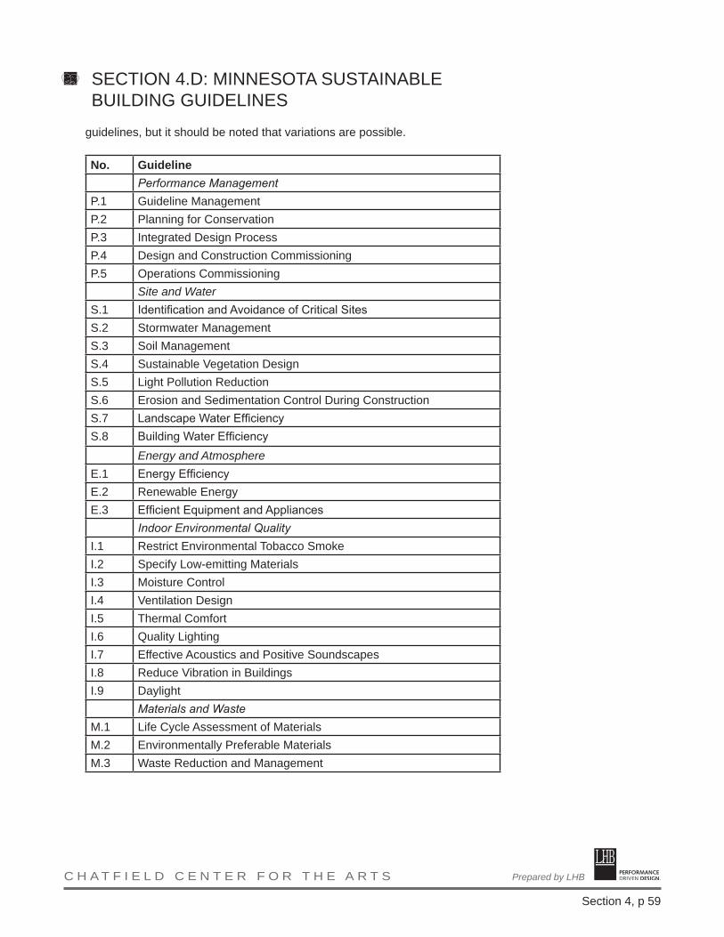
PERFORMANCE DRIVEN DESIGN.Prepared by LHB C H A T F I E L D C E N T E R F O R T H E A R T S
Section 4, p 59
guidelines, but it should be noted that variations are possible.
No. GuidelinePerformance Management
P.1 Guideline ManagementP.2 Planning for ConservationP.3 Integrated Design ProcessP.4 Design and Construction CommissioningP.5 Operations Commissioning
Site and WaterS.1 Identification and Avoidance of Critical SitesS.2 Stormwater ManagementS.3 Soil ManagementS.4 Sustainable Vegetation DesignS.5 Light Pollution ReductionS.6 Erosion and Sedimentation Control During ConstructionS.7 Landscape Water EfficiencyS.8 Building Water Efficiency
Energy and AtmosphereE.1 Energy EfficiencyE.2 Renewable EnergyE.3 Efficient Equipment and Appliances
Indoor Environmental QualityI.1 Restrict Environmental Tobacco SmokeI.2 Specify Low-emitting MaterialsI.3 Moisture ControlI.4 Ventilation DesignI.5 Thermal ComfortI.6 Quality LightingI.7 Effective Acoustics and Positive SoundscapesI.8 Reduce Vibration in BuildingsI.9 Daylight
Materials and WasteM.1 Life Cycle Assessment of MaterialsM.2 Environmentally Preferable MaterialsM.3 Waste Reduction and Management
SECTION 4.D: MINNESOTA SUSTAINABLE BUILDING GUIDELINES

PERFORMANCE DRIVEN DESIGN.Prepared by LHB C H A T F I E L D C E N T E R F O R T H E A R T S
Section 4, p 60
STATUTERequired
by Funding Recipient
1. §16B.241Coordinated Facility Planning
Yes(Required)
2. §16B.32, Subd 1Alternative Energy Sources
Yes
3. §16B.32, Subd 1aRenewable Energy Sources - 2% of energy useSolar or Wind
Yes
4. §16B.32, Subd 2Energy Conservation Goals (may participate in Program – not mandatory)
Yes
5. §16B.325Apply Sustainable Guidelines (B3-MSBG)(New Bldgs & Major Renovations – See Applicability Criteria athttp://www.msbg.umn.edu)5b: §216B.241 Sustainable Building 2030 requirements
Yes
6. §16B.326Written plan w/predesign to consider providing Geothermal & Solar Energy Heating & Cooling Systems on new or replacement HVAC systems
Yes
7. §16B.33State Designer Selection Board
Yes
8. §16B.335, Subd 1, Notification to House & Senate Committees Yes
9. §16B.335, Subd 3Predesign SubmittalSee Statute for exempted projects
Yes
10. §16B.335, Subd 4Energy Conservation Standards( Minnesota Energy Code MN Rule 7676)
Yes
11. §16B.335, Subd 5 & 6Information Tech. Review by OET
Yes
12. §16B.335, Subd. 3cConsider the use of MINNCOR productswww.minncor.com
Yes
13. §16B.35 % for ArtWhen considered in original legislative request; & when constn is $500K or greater
Yes
SECTION 4.F: STATUTE REQUIREMENTS
PERFORMANCE DRIVEN DESIGN.Prepared by LHB C H A T F I E L D C E N T E R F O R T H E A R T S
Section 4, p 61
PROJECT DELIVERY METHODThe project will be delivered with the use of a Construction Manager. The primary purpose of this method of delivery is to gain the benefits associated with using contractors with specific skill sets on those elements of the project that demand that level of expertise.
Due to the complexity of the project, a construction manager will be brought on early, before the end of design.
SECTION 4.H: PROJECT PROCUREMENT AND DELIVERY

PERFORMANCE DRIVEN DESIGN.Prepared by LHB C H A T F I E L D C E N T E R F O R T H E A R T S
Section 5, p 1
BUILDING GROUNDSTreatment of the building grounds will be guided by the concept of rehabilitation. The open space areas would be set aside for pedestrians and provide for multiple uses, including outdoor exhibits and special events. It is anticipated that the parts of the property adjoining Town Square Park will quickly evolve into a people-oriented outdoor destination in its own right.
Spatial Organization and Setbacks
• The School Block physically and historically comprises a specific environment with its own unique identity of time and space. New landscape architecture needs to respect the spatial relationships between component elements of the property and downtown streetscape.
• The existing building setbacks from public streets should be retained.
• Redevelopment should not include large areas of off-street parking anywhere inside the boundaries of the historic property (except for restricted parking along Fourth Street and temporary truck parking in the service areas behind the auditorium). This will need to be balanced with city zoning requirements related to parking.
Topography and Landscaping
• Identify, retain, and preserve historic topographic features, including lawns and circulation features.
• Preserve existing grades and land surfaces except to correct drainage problems.
• Evaluate the condition and determine the age of the historic retaining wall along Fifth Street; stabilize, protect, and maintain the historic stone work and replace in-kind those portions which are too deteriorated to repair; the new stone work should match the original in composition, color, and texture.
Vegetation
• Identify and retain trees, shrubbery and other plantings that reflect the history and development of the property, particularly those which were in place during its period of historic significance.
• Install new plantings that are compatible with the historic character of the property.
• Monitor the age, health and vigor of boulevard trees.
• Recognize that day-to-day, seasonal, and cyclical grounds keeping and
SECTION 5: SITE ANALYSIS AND SELECTION
PERFORMANCE DRIVEN DESIGN.Prepared by LHB C H A T F I E L D C E N T E R F O R T H E A R T S
Section 5, p 2
other horticultural tasks can cumulatively alter the character of the historic landscape.
Circulation
• Retain the walkways that have traditionally linked the historic buildings to their environment.
• Maintenance and repair of walkways should emphasize retention of the maximum amount of existing concrete surface while utilizing as little new material as possible; repairs to existing walkways should be non-destructive.
• Limited replacement in-kind of missing or extensively deteriorated portions of historic walkways and steps would be appropriate; the replacement material should match the historic surfaces both physically and visually.
• New walkways and steps should be physically and visually compatible with historic structures.
Structures, Furnishings & Objects
• Install new street lights, benches, and signs that are visually compatible with the character and mood of the historic property.
Accessibility
• Because accessibility to historic buildings is required by the Americans with Disabilities Act, it may be necessary to modify some existing landscape features, such as walkways and vehicle parking areas, to bring them into compliance with accessibility code requirements; the goal is to provide the highest level of access with the lowest level of impact on the integrity of historic landscape features.
• Properly designed and installed ramps for handicap accessibility should not detract from the historic integrity of the buildings and their setting.
City Park
• The historic town square park is a historically significant vernacular landscape feature that contributes to the historic character of the Center for the Arts; planning for future park improvements must strike a balance between change and continuity.
• Arrange for an intensive historic preservation study of the park to reconstruct in detail the history of its development and public use, document historically important landscape features, and evaluate its historic significance and integrity. If eligible, the park should be nominated
SECTION 5: SITE ANALYSIS AND SELECTION
PERFORMANCE DRIVEN DESIGN.Prepared by LHB C H A T F I E L D C E N T E R F O R T H E A R T S
Section 5, p 3
to the National Register of Historic Places and designated as Chatfield Heritage Landmark.
• Preserve trees, walkways, structures, and objects that contribute to the historic significance of the park and are therefore worthy of preservation.
• The programmatic needs of the city park need to be balanced against historic preservation requirements.
ZONING SUMMARYZoning review was performed using the Municode.com link and zoning map pro-vided on the City of Chatfield website.
PROPERTY INFORMATION1. Address:
405 Main Street SouthChatfield, MN 55923
2. County: Chatfield is divided between Olmsted and Fillmore Counties. The project site is located in Fillmore County
3. PIN: 2602310004. Watershed District:5. Parcel Size: 6. Legal Description: CHATFIELDS ORIGINAL PLAT
lot-1-5 Block-019 LOTS 1-7. Existing Building Footprint:
PRIMARY ZONING INFORMATION1. Primary Zoning District: R-1 per zoning map dated 12/20/12
a. Allowable uses include: Public Recreation, including parks and playgrounds; Historic sites and structuresb. Conditional uses include: City buildings and structures
2. Flood and Wetlands: None, per Chatfield planning map
PROJECT REQUIREMENTS1. Performance Standards: Structure height, yard requirements, lot area, lot
dimensions, and coverage not reviewed due to the project focuses on an existing building with the addition replacing a portion of the 1936 structure.
2. Parkinga. Minimum Requirements for “Theaters, stadiums, arenas, auditoriums,
halls, and similar places: One parking space for every three persons based on building occupancy standards. 50% of the total spaces required must be on-site. The remaining 50% of spaces must be within a 300-foot radius of the building.
b. Required aisle width varies with parking stall angle and service type (one-or two-way). See Sec. 113-412.
c. 30% of the spaces may be designated for compact carsi. Compact Parking Space: 8’-0” wide x 16’-0” in length
SECTION 5: SITE ANALYSIS AND SELECTION
PERFORMANCE DRIVEN DESIGN.Prepared by LHB C H A T F I E L D C E N T E R F O R T H E A R T S
Section 5, p 4
ii. Standard Parking Space: 9’-0” wide x 18’-0” in lengthd. Disabled parking requirements
i. Individual parking spaces shall be 14’-0” x 18’-0”. However, this may include a 5’-0” access aisle which is non-compliant with State codes.
ii. Regulations for two adjacent disabled parking stalls reference a 5’-0” wide access aisle which is non-compliant with State codes.
iii. Disabled parking shall be clearly identified. 3. Access Drives
a. Access drives may be located adjacent to property lines, unless consisting of a non-finished surface, such as crushed rock.b. Minimum widths
i. One-way service: 10 feetii. Two-way service: 20 feet
4. Landscapinga. Where setbacks exist or are required, a 10 foot deep landscaped yard
shall be provided, which may include grass or decorative stones, shrubs, or trees, along all streets.
5. Soil removal, erosion, and sedimentation control (per Sec. 113-267)6. Loading: No specific requirements were found.7. Signage: No specific requirements were found.
INITIAL FINDINGS:
1. A Conditional Use Permit may be required.2. Parking requirements, based on 2,113 occupants: 705 stalls are needed,
353 of which are required to be on-site. This assumes all areas of the building are fully occupied. However, after discussion with the city planner, a variance to decrease parking would likely be approved based on the historic use of the structure.
3. Historical Preservation review will be required per Chapter 107, but details on the approval process are not clear at this time.
4. Stormwater management – Section 113-267 does not appear to require specific runoff rates or quantities. Stormwater management standards to be confirmed, but initial discussion with the city engineer indicates no specific rate or quantities will need to be met.
SECTION 5: SITE ANALYSIS AND SELECTION
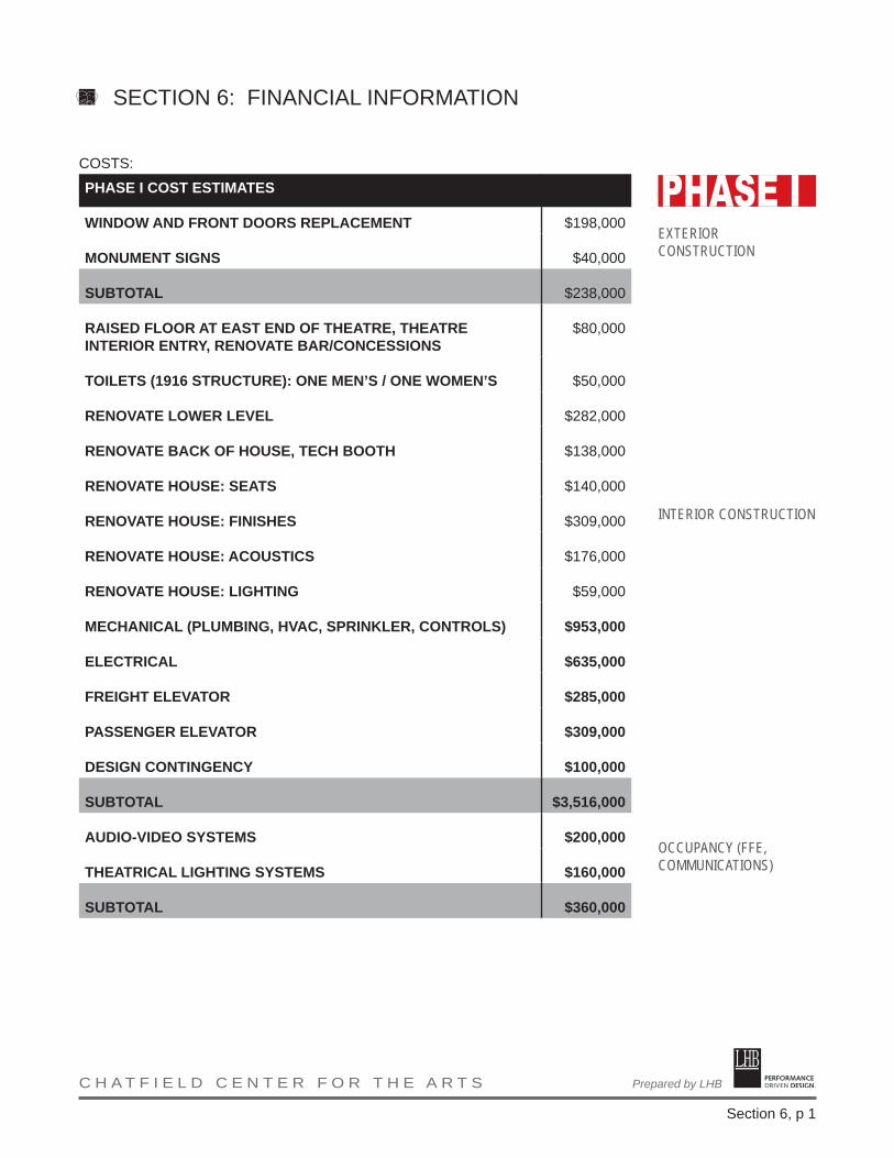
PERFORMANCE DRIVEN DESIGN.Prepared by LHB C H A T F I E L D C E N T E R F O R T H E A R T S
Section 6, p 1
COSTS:
PHASE I COST ESTIMATES
WINDOW AND FRONT DOORS REPLACEMENT $198,000
MONUMENT SIGNS $40,000
SUBTOTAL $238,000
RAISED FLOOR AT EAST END OF THEATRE, THEATRE INTERIOR ENTRY, RENOVATE BAR/CONCESSIONS
$80,000
TOILETS (1916 STRUCTURE): ONE MEN’S / ONE WOMEN’S $50,000
RENOVATE LOWER LEVEL $282,000
RENOVATE BACK OF HOUSE, TECH BOOTH $138,000
RENOVATE HOUSE: SEATS $140,000
RENOVATE HOUSE: FINISHES $309,000
RENOVATE HOUSE: ACOUSTICS $176,000
RENOVATE HOUSE: LIGHTING $59,000
MECHANICAL (PLUMBING, HVAC, SPRINKLER, CONTROLS) $953,000
ELECTRICAL $635,000
FREIGHT ELEVATOR $285,000
PASSENGER ELEVATOR $309,000
DESIGN CONTINGENCY $100,000
SUBTOTAL $3,516,000
AUDIO-VIDEO SYSTEMS $200,000
THEATRICAL LIGHTING SYSTEMS $160,000
SUBTOTAL $360,000
SECTION 6: FINANCIAL INFORMATION
EXTERIOR CONSTRUCTION
INTERIOR CONSTRUCTION
OCCUPANCY (FFE, COMMUNICATIONS)

PERFORMANCE DRIVEN DESIGN.Prepared by LHB C H A T F I E L D C E N T E R F O R T H E A R T S
Section 6, p 2
SUMMARY
PHASE I COST ESTIMATE SUMMARY
PREDESIGN $44,000
DESIGN FEES $410,516
PROJECT MANAGEMENT* $103,260
CONSTRUCTION COSTS
CONSTRUCTION (General Construction, Site, Utilities, Mechanical, Electrical, Plumbing, Etc.)
$3,749,000
CONTINGENCY (10%) $374,900
HAZARDOUS MATERIALS ABATEMENT (Allowance) $25,000
CONSTRUCTION MANAGEMENT FEE $187,450
OWNER CONTINGENCY (Allowance) $50,000
ART (1%) $37,490
OCCUPANCY (FFE; Communications) $360,000
TOTAL $5,341,616
STATE FUNDING AMOUNT $5,342,000
*PROJECT MANAGEMENT COSTS (PHASE I)Geotech (Accepted proposal) $3,620Survey (Accepted proposal) $3,600Existing Structural Analysis $7,500Historical Consultant (Proposal from Pathfinder) $36,000Testing/Observation (1%) $37,540Acoustical (Pending Proposal) $15,000Total $103,260
SECTION 6: FINANCIAL INFORMATION

PERFORMANCE DRIVEN DESIGN.Prepared by LHB C H A T F I E L D C E N T E R F O R T H E A R T S
Section 6, p 3
EXTERIOR CONSTRUCTION
INTERIOR CONSTRUCTION
PHASE II COST ESTIMATES
STEP REPLACEMENT $57,000
COPING REPAIR $13,000
MINOR FAÇADE REHABILITATION $91,000
RENOVATE BACK OF HOUSE, RECEIVING ADDITION $138,000
ORCHESTRA PIT $412,000
BALCONY SEAT REPLACEMENT $50,000
LANDSCAPING AND PARKING $86,000
LIGHTING AT AUDITORIUM ENTRY ONLY $12,000
SUBTOTAL $859,000
DEMO EXISTING LINK; CONSTRUCTION NEW LINK WITH CATWALK CONNECTION
$828,000
DEMO GARAGE. WATERPROOF EXISTING SUB-BASEMENT $48,000
RENOVATE 1916 STRUCTURE $862,000
RESTORE SKYLIGHTS $75,000
ADD TOILETS, 1916 STRUCTURE (2 MEN’S, 2 WOMEN’S) $209,000
ADDITIONAL TOILET RENOVATIONS (PREVIOUS PHASE I) $171,000
LANDSCAPING AND PARKING - 1916 SCHOOL $128,000
LANDSCAPING AND PARKING - THEATER $86,000
MECHANICAL $969,000
ELECTRICAL $479,000
REPAIRS TO NORTH FAÇADE: BRICK INFILL AND WINDOWS $60,000
DESIGN CONTINGENCY $250,000
SUBTOTAL $4,165,000
SECTION 6: FINANCIAL INFORMATION
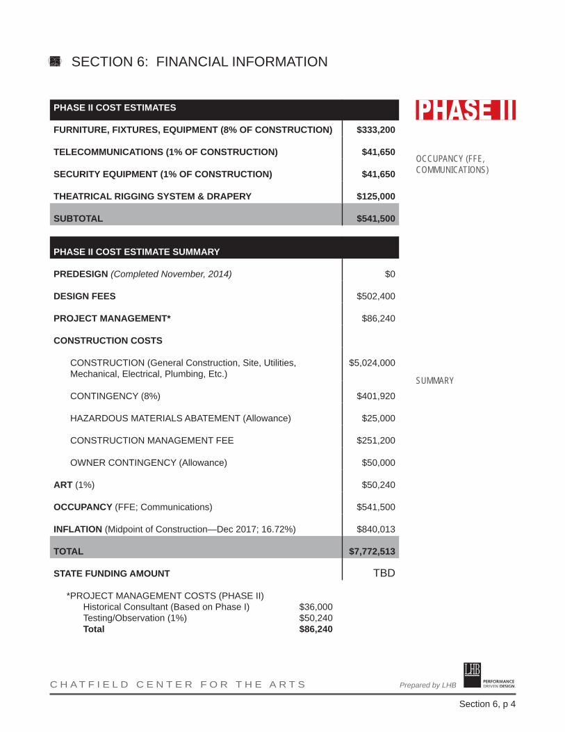
PERFORMANCE DRIVEN DESIGN.Prepared by LHB C H A T F I E L D C E N T E R F O R T H E A R T S
Section 6, p 4
OCCUPANCY (FFE, COMMUNICATIONS)
SUMMARY
PHASE II COST ESTIMATES
FURNITURE, FIXTURES, EQUIPMENT (8% OF CONSTRUCTION) $333,200
TELECOMMUNICATIONS (1% OF CONSTRUCTION) $41,650
SECURITY EQUIPMENT (1% OF CONSTRUCTION) $41,650
THEATRICAL RIGGING SYSTEM & DRAPERY $125,000
SUBTOTAL $541,500
PHASE II COST ESTIMATE SUMMARY
PREDESIGN (Completed November, 2014) $0
DESIGN FEES $502,400
PROJECT MANAGEMENT* $86,240
CONSTRUCTION COSTS
CONSTRUCTION (General Construction, Site, Utilities, Mechanical, Electrical, Plumbing, Etc.)
$5,024,000
CONTINGENCY (8%) $401,920
HAZARDOUS MATERIALS ABATEMENT (Allowance) $25,000
CONSTRUCTION MANAGEMENT FEE $251,200
OWNER CONTINGENCY (Allowance) $50,000
ART (1%) $50,240
OCCUPANCY (FFE; Communications) $541,500
INFLATION (Midpoint of Construction—Dec 2017; 16.72%) $840,013
TOTAL $7,772,513
STATE FUNDING AMOUNT TBD
*PROJECT MANAGEMENT COSTS (PHASE II)Historical Consultant (Based on Phase I) $36,000Testing/Observation (1%) $50,240Total $86,240
SECTION 6: FINANCIAL INFORMATION
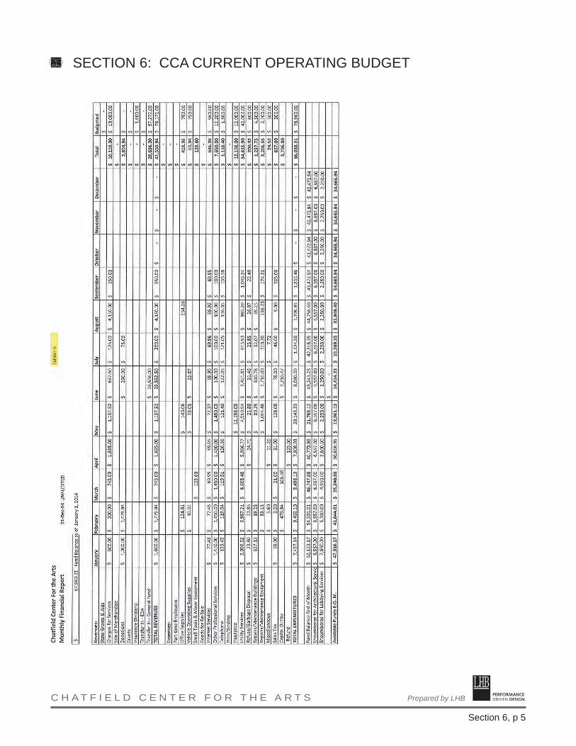
PERFORMANCE DRIVEN DESIGN.Prepared by LHB C H A T F I E L D C E N T E R F O R T H E A R T S
Section 6, p 5
SECTION 6: CCA CURRENT OPERATING BUDGET

PERFORMANCE DRIVEN DESIGN.Prepared by LHB C H A T F I E L D C E N T E R F O R T H E A R T S
Section 6, p 6
SECTION 6: CCA CURRENT OPERATING BUDGET
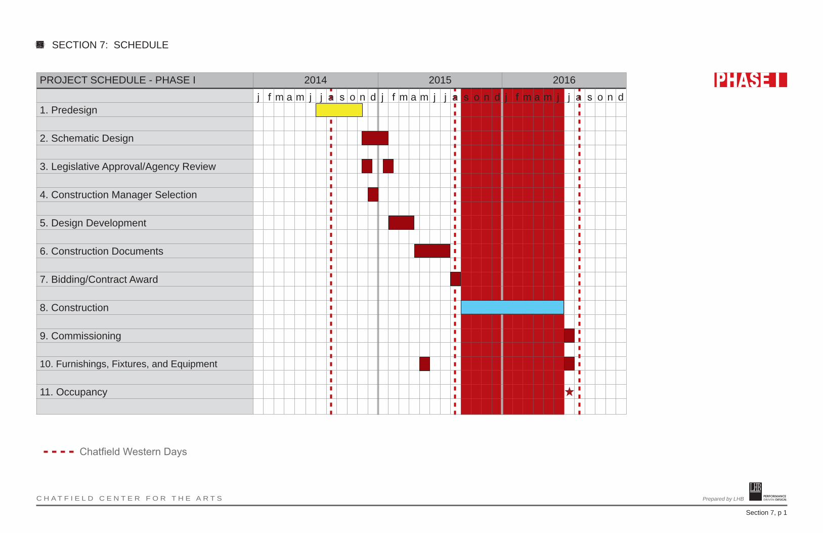
PERFORMANCE DRIVEN DESIGN.Prepared by LHB C H A T F I E L D C E N T E R F O R T H E A R T S
Section 7, p 1
SECTION 7: SCHEDULE
PROJECT SCHEDULE - PHASE I 2014 2015 2016
1. Predesign
2. Schematic Design
3. Legislative Approval/Agency Review
4. Construction Manager Selection
5. Design Development
6. Construction Documents
7. Bidding/Contract Award
8. Construction
9. Commissioning
10. Furnishings, Fixtures, and Equipment
11. Occupancy
j f m a m j j a s o n d
Chatfield Western Days
j f m a m j j a s o n d j f m a m j j a s o n d
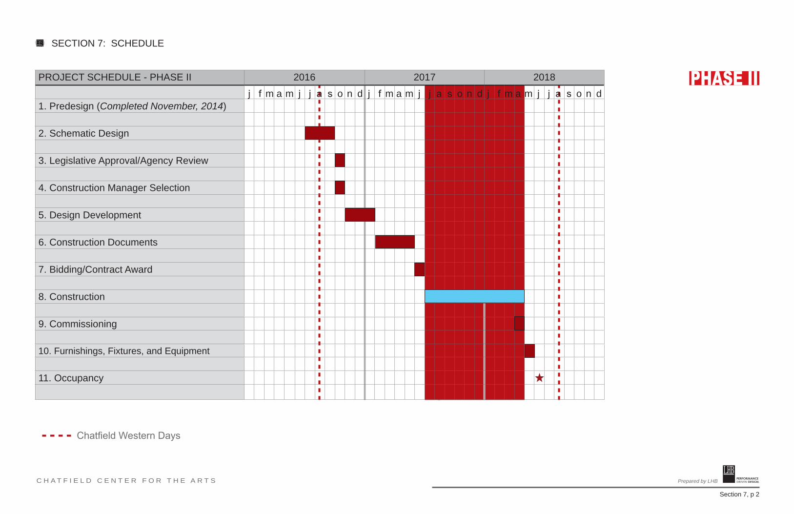
PERFORMANCE DRIVEN DESIGN.Prepared by LHB C H A T F I E L D C E N T E R F O R T H E A R T S
Section 7, p 2
PROJECT SCHEDULE - PHASE II 2016 2017 2018
1. Predesign (Completed November, 2014)
2. Schematic Design
3. Legislative Approval/Agency Review
4. Construction Manager Selection
5. Design Development
6. Construction Documents
7. Bidding/Contract Award
8. Construction
9. Commissioning
10. Furnishings, Fixtures, and Equipment
11. Occupancy
j f m a m j j a s o n d
Chatfield Western Days
j f m a m j j a s o n d j f m a m j j a s o n d
SECTION 7: SCHEDULE

PERFORMANCE DRIVEN DESIGN.Prepared by LHB C H A T F I E L D C E N T E R F O R T H E A R T S
1
Meeting Minutes DATE: July 24, 2014 FROM: Sara G. Phillips, AIA RE: Chatfield Center for the Arts Predesign Meeting 1 PRESENT: Carmen Narveson, Chatfield Brass Band F. Mike Tuohy, CCA Robert Vogel, HPC Molly Baum, CCA and EDA Chris Giesen, EDA Joel Young, City of Chatfield Carla Gallina, GDCCC Russ Smith, City of CCA Board Joe Chase, Wits End Theatre Michael Martin, City of Kasson Steve Harmon, Dunham Associates Robyn Loewen, Wits End Theatre/Music Performance Tony Cole, CCA Bruce Cornwall, LHB Sara Phillips, LHB After introductions and opening remarks, a discussion was held on various site and building issues and concepts. It was noted that the predesign should establish the entire scope of the project, even if the work will exceed current available funding, possibly resulting in a phased project with additional fundraising or bonding required. General Background:
• Stakeholder meetings were held as part of previous planning efforts. • Current sentiment may be to leave the interior spaces largely as is, leaving the school
rooms for general use purposes, rather than specialized uses (art studios). • Art culture in Chatfield was noted as strong, and attendees noted the building use should
be used for arts purposes. • The Legion Room was noted as a good example of a mixed use space. It is currently
used for concerts, comedy shows, and occasional graduation events. Predesign Document
• It was noted that a predesign is required by the State and the purpose is to outline desired uses, potential costs, and provide a framework for the future design.
• The Department of Administration will approve the predesign, with an initial meeting occurring soon.
APPENDIX: PREDESIGN MEETING MINUTES
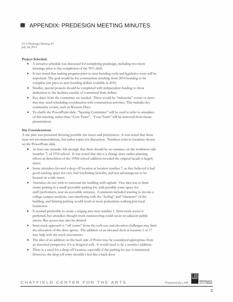
PERFORMANCE DRIVEN DESIGN.Prepared by LHB C H A T F I E L D C E N T E R F O R T H E A R T S
2
APPENDIX: PREDESIGN MEETING MINUTES
CCA Predesign Meeting #1 July 24, 2014
Project Schedule
• A tentative schedule was discussed for completing predesign, including two more meetings prior to the completion of the 95% draft.
• It was noted that making progress prior to next bonding cycle and legislative tours will be important. The goal would be for construction resulting from 2014 bonding to be complete just prior to next bonding dollars available in 2016.
• Smaller, special projects should be completed with independent funding to show dedication to the facilities outside of committed State dollars.
• Key dates from the committee are needed. These would be “milestone” events or dates that may need scheduling coordination with construction activities. This includes key community events, such as Western Days.
• To clarify the PowerPoint slide, “Steering Committee” will be used to refer to attendees of this meeting, rather than “Core Team”. “Core Team” will be removed from future presentations.
Site Considerations A site plan was presented showing possible site issues and preferences. It was noted that these were not recommendations, but rather topics for discussion. Numbers refer to locations shown on the PowerPoint slide.
• At least one attendee felt strongly that there should be no entrance on the northwest side (number 7) of 1916 school. It was noted that this is a change since earlier planning efforts as demolition of the 1950s school addition revealed the original facade is largely intact.
• Some attendees favored a drop off location at location number 7, as they believed it had good stacking space for cars, had wayfinding benefits, and was advantageous to be located on a side street.
• Attendees do not wish to surround the building with asphalt. One idea was to limit onsite parking to a small accessible parking lot, with possibly some space for staff/performers, near an accessible entrance. Comments included wanting to invoke a college campus aesthetic, cars interfering with the “feeling” and “character” of the building, and limiting parking would result in more pedestrians walking past local businesses.
• It seemed preferable to create a staging area near number 1. Semi-truck access is preferred, but attendees thought truck maneuvering could occur on adjacent public streets. Bus access may also be desired.
• Semi-truck approach is “off center” from the curb cut, and elevation challenges may limit the relocation of the drive apron. The addition of an elevated dock at location 1 or 17 may help with the truck movements.
• The idea of an addition on the back side of Potter may be considered appropriate from an historical perspective if it is designed well. It would need to be a sensitive addition.
• There is a need for a drop-off location, especially if the parking lot size is minimized. However, the drop-off entry shouldn’t feel like a back door.

PERFORMANCE DRIVEN DESIGN.Prepared by LHB C H A T F I E L D C E N T E R F O R T H E A R T S
3
CCA Predesign Meeting #1 July 24, 2014
• There was some reservation about having a main accessible entrance on the southwest side of the building. Some felt this would turn the “back” of the building into the “front”.
• From an historical perspective, a modern, accessible entrance seems to be preferred at locations 5 or 6. A transparent (glass) structure was originally envisioned, including the demolition of the original connecting link.
• It was expressed that the shed over the former coal room should be demolished. It was noted that this would require either demolition/infill of the coal room or proper waterproofing of the roof/walls.
• A good information sign is needed along the highway, but there does not seem to be a strong preference for location as no sign was historically present. Locations 14, 13, or near 11 were discussed.
• It was noted that the south entrance needs to remain as a fire exit. • Sidewalks have been restored to historic placement and seem to work well. Others
questioned if additional sidewalks are needed on the park (northwest) side of the building. • There seems to be a desire to maintain use of the existing northeast doors to the 1916
school and Potter Auditorium. However, this may create logistical issues for ticket taking at events.
Floor Plans Floor plans were presented showing possible resolutions to issues noted in previous planning efforts. It was noted that these were not recommendations, but rather topics for discussion. Numbers refer to locations shown on the PowerPoint slide. Basement Level
• It was questioned if the space under the “shed” is needed. Attendees noted not much was in the space now, but it may be needed for mechanical systems or storage.
• It was noted that the water table is high, with some basement areas being “damp” occasionally.
• The initial concept showed a combo passenger/freight elevator. First Level
• There was a general concern with eliminating seats on the first level. It was noted that these seats have better sightlines and are sold at a higher cost than general admission ones (balcony seats).
• Side seats can have poor sightlines for events held deep in the stage, primarily the right side. This, however, varies by performance.
• A flat ring around first floor was indicated for accessibility and a link to a new lobby space. Some were concerned by the reduction in seating.
• The existing lobby doesn’t have enough space and becomes congested. It was noted that resolution of this issue would require moving the interior wall into the theater and therefore reducing the number of seats. Those seats were characterized as “prime”.
APPENDIX: PREDESIGN MEETING MINUTES
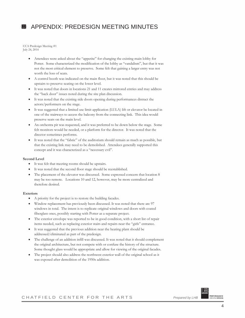
PERFORMANCE DRIVEN DESIGN.Prepared by LHB C H A T F I E L D C E N T E R F O R T H E A R T S
4
CCA Predesign Meeting #1 July 24, 2014
• Attendees were asked about the “appetite” for changing the existing main lobby for Potter. Some characterized the modification of the lobby as “vandalism”, but that it was not the most critical element to preserve. Some felt that gaining a larger entry was not worth the loss of seats.
• A control booth was indicated on the main floor, but it was noted that this should be upstairs to preserve seating on the lower level.
• It was noted that doors in locations 21 and 11 creates mirrored entries and may address the “back door” issues noted during the site plan discussion.
• It was noted that the existing side doors opening during performances distract the actors/performers on the stage.
• It was suggested that a limited use limit application (LULA) lift or elevator be located in one of the stairways to access the balcony from the connecting link. This idea would preserve seats on the main level.
• An orchestra pit was requested, and it was preferred to be down below the stage. Some felt monitors would be needed, or a platform for the director. It was noted that the director sometimes performs.
• It was noted that the “fabric” of the auditorium should remain as much as possible, but that the existing link may need to be demolished. Attendees generally supported this concept and it was characterized as a “necessary evil”.
Second Level
• It was felt that meeting rooms should be upstairs. • It was noted that the second floor stage should be reestablished. • The placement of the elevator was discussed. Some expressed concern that location 8
may be too remote. Locations 10 and 12, however, may be more centralized and therefore desired.
Exteriors
• A priority for the project is to restore the building facades. • Window replacement has previously been discussed. It was noted that there are 97
windows in total. The intent is to replicate original windows and doors with coated fiberglass ones, possibly starting with Potter as a separate project.
• The exterior envelope was reported to be in good condition, with a short list of repair items needed, such as replacing exterior stairs and repairs near the “girls” entrance.
• It was suggested that the previous addition near the heating plant should be addressed/eliminated as part of the predesign.
• The challenge of an addition infill was discussed. It was noted that it should complement the original architecture, but not compete with or confuse the history of the structure. Some thought glass would be appropriate and allow for viewing of the original facades.
• The project should also address the northwest exterior wall of the original school as it was exposed after demolition of the 1950s addition.
APPENDIX: PREDESIGN MEETING MINUTES

PERFORMANCE DRIVEN DESIGN.Prepared by LHB C H A T F I E L D C E N T E R F O R T H E A R T S
5
CCA Predesign Meeting #1 July 24, 2014
Additional Items
• It was noted that Dunham has done an initial report on the mechanical and electrical systems. Most are at the end of their life expectancy, but portions of the ventilation system may be considered historically significant.
• Project costs were discussed and it was clarified that the available funding needs to cover project management fees, professional fees, and other items outside of the cost of construction.
• It was noted that there is no percentage for arts requirement, but the committee may want to address artwork as part of the project due to their commitment to the arts.
This constitutes my understanding of items discussed and decisions reached. If there are any omissions or discrepancies, please notify the author in writing. c: 140378, 304 M:\14Proj\140378\300 Communication\304 Minutes\140378MM072414 CCA Predesign Meeting 1.docx
APPENDIX: PREDESIGN MEETING MINUTES
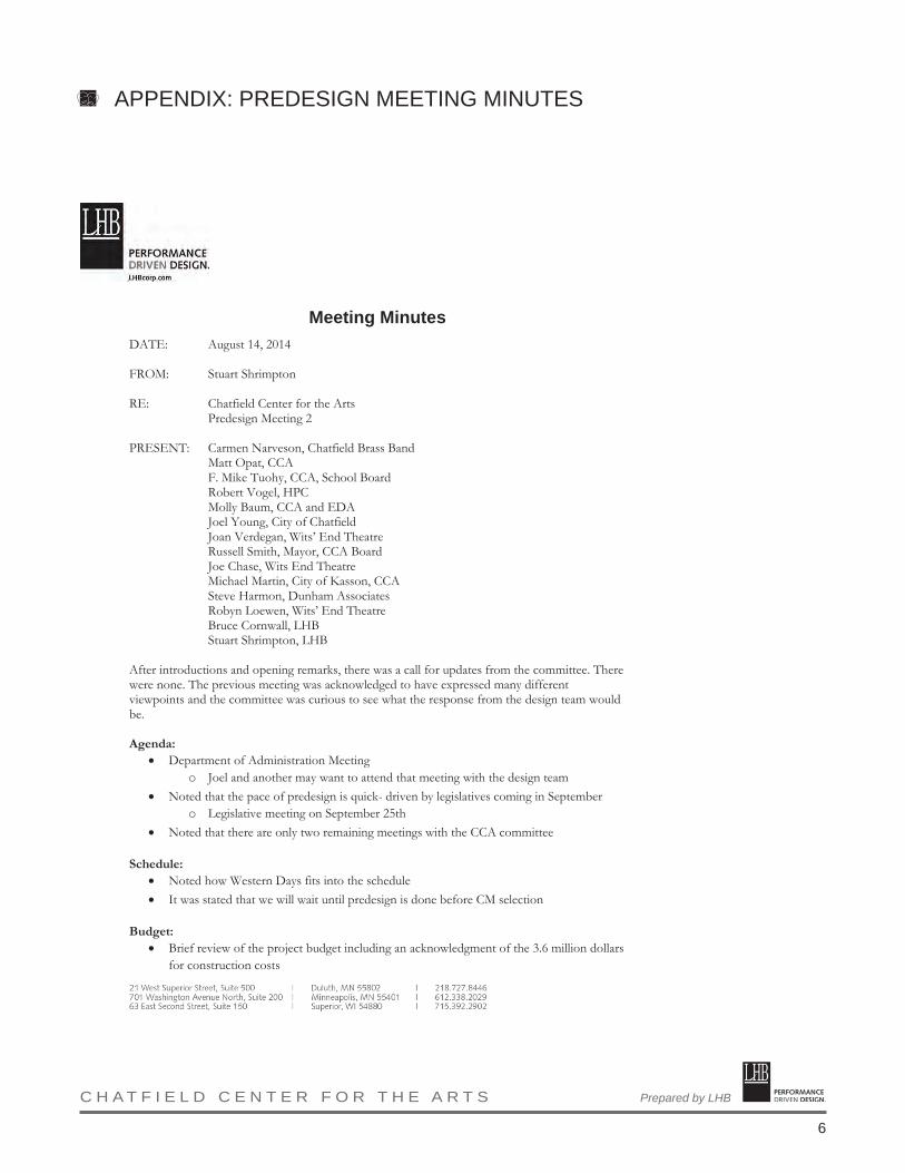
PERFORMANCE DRIVEN DESIGN.Prepared by LHB C H A T F I E L D C E N T E R F O R T H E A R T S
6
Meeting Minutes DATE: August 14, 2014 FROM: Stuart Shrimpton RE: Chatfield Center for the Arts Predesign Meeting 2 PRESENT: Carmen Narveson, Chatfield Brass Band Matt Opat, CCA F. Mike Tuohy, CCA, School Board Robert Vogel, HPC Molly Baum, CCA and EDA Joel Young, City of Chatfield Joan Verdegan, Wits’ End Theatre Russell Smith, Mayor, CCA Board Joe Chase, Wits End Theatre Michael Martin, City of Kasson, CCA Steve Harmon, Dunham Associates Robyn Loewen, Wits’ End Theatre Bruce Cornwall, LHB Stuart Shrimpton, LHB After introductions and opening remarks, there was a call for updates from the committee. There were none. The previous meeting was acknowledged to have expressed many different viewpoints and the committee was curious to see what the response from the design team would be. Agenda:
• Department of Administration Meeting o Joel and another may want to attend that meeting with the design team
• Noted that the pace of predesign is quick- driven by legislatives coming in September o Legislative meeting on September 25th
• Noted that there are only two remaining meetings with the CCA committee Schedule:
• Noted how Western Days fits into the schedule • It was stated that we will wait until predesign is done before CM selection
Budget:
• Brief review of the project budget including an acknowledgment of the 3.6 million dollars for construction costs
APPENDIX: PREDESIGN MEETING MINUTES

PERFORMANCE DRIVEN DESIGN.Prepared by LHB C H A T F I E L D C E N T E R F O R T H E A R T S
7
CCA Predesign Meeting #2 August 14, 2014
Site Considerations A site aerial and plan were presented. It was noted that the images were design considerations, not solutions. Numbers refer to locations shown on the PowerPoint slide.
• There was a call to address signage on the plan o There was emphasis that decisions about signage can be made on an ongoing
basis. • One attendee favored 7 & 12 “reaching out to park” and suggested that more could be
done to develop the connection to the park • There was general concern that the number of parking spaces was not sufficient • One comment suggested that the distance from parking to the entrances was too far • Some discussion suggested making 4th Street a pedestrian only street, acknowledging that
that had been done during school hours and makes the park tie into the block o It was noted that none of the dollars for the project are for the street
• One attendee suggested a single-loaded loop with a larger parking lot with a larger loading zone/parking area behind the auditorium.
• There was a call for truck access to the catering area • Generally agreed upon that accesses (curb cuts) from the rectory and the site could align • One attendee suggested that the old (1880s) building footprint could be made part of the
parking lot • Some questioned the effect that pulling 9 toward Main Street would have on preserving
the facades. • Suggestion to use space at 8-9 for interior as opposed to only respecting the old.
o Noted that when 600 people get up at intermission, the building doesn’t have a lot of room for people.
o R. Vogel indicated that working with a historic façade on main street is delicate • There was a question about the 1880s footprint
o One suggestion was to somehow marker the corners of the original building. o Another idea was to outline the old footprint in the parking area
It was noted that design details would be addressed at the schematic phase o Another idea suggested parking screening in the shape of the old building
• Noted that there are lots of details to work out about the entrances
Floor Plans Floor plans were presented showing possibilities based upon feedback from the previous meeting. It was noted that these were topics for discussion. Numbers refer to locations shown on the PowerPoint slide. Comments were received after all plans were presented.
• It was noted that the elevator seemed to be driving too much and took away views of seats. As the boardroom isn’t used much, the suggestion was made that the elevator could be somewhere else.
• There was general concern about losing seats on the main floor
APPENDIX: PREDESIGN MEETING MINUTES

PERFORMANCE DRIVEN DESIGN.Prepared by LHB C H A T F I E L D C E N T E R F O R T H E A R T S
8
CCA Predesign Meeting #2 August 14, 2014
• The difficulty of resolving the different levels was noted • It was noted that the law states that the balcony must be made accessible • Ramps were suggested as a means of getting to the balcony • It was noted that the drawings were not making a case for particular strategies at this
point • The suggestion was made to fill in more area between the buildings with some thinking
that more space could provide additional options for managing the level changes • It was noted that further exploration of elevator and ramp locations will be made • The question was raised as to whether the entry to Potter could be moved closer to 6 • The question was raised as to where the box office would be located
o It was noted that if the entrance remains at 10, or in that general area, there would be issues with box office location
• The suggestion was made to put the elevator at 10 (on the Second floor plan) • It was noted that the elevator would not be solved in predesign
o It was noted that building in the 1916 building will come in another phase and will complicate the elevator issue
• A general inquiry was raised about building in the attic space of the auditorium o It was noted that that would be for another time
Program on First Floor
• 14: bathrooms • 16: Noted that there would be no permanent dividers in gym • 20: Catering kitchen located for access and smells
Second Level
• Noted that the assembly hall and stage would be restored • Noted that the bathrooms stack from first floor • 15: Noted that a ramp will be needed to access the stage • There was a call for the wording to be “studios” and not classrooms as a designation
o The comment was made that there may be artists in residence at times for a month or so
• There was some discussion of the historic archives going in 16 on second level • Noted that 14 could be reserved for a meeting room • The name studios was favored for the spaces labeled classrooms • One attendee cited the popularity of certain social events where a group of people pair
wine with painting as an example of what art in the space might mean • There was a call for storage space for tables and chairs to be used for events • The design team noted that they would refine storage ideas
Electrical
• There was a description of the current electrical service routing through the buildings
APPENDIX: PREDESIGN MEETING MINUTES
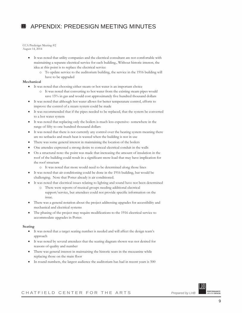
PERFORMANCE DRIVEN DESIGN.Prepared by LHB C H A T F I E L D C E N T E R F O R T H E A R T S
9
CCA Predesign Meeting #2 August 14, 2014
• It was noted that utility companies and the electrical consultant are not comfortable with maintaining a separate electrical service for each building., Without historic interest, the idea at this point is to replace the electrical service
o To update service to the auditorium building, the service in the 1916 building will have to be upgraded
Mechanical • It was noted that choosing either steam or hot water is an important choice
o It was noted that converting to hot water from the existing steam pipes would save 15% in gas and would cost approximately five hundred thousand dollars
• It was noted that although hot water allows for better temperature control, efforts to improve the control of a steam system could be made
• It was recommended that if the pipes needed to be replaced, that the system be converted to a hot water system
• It was noted that replacing only the boilers is much less expensive- somewhere in the range of fifty to one hundred thousand dollars
• It was noted that there is not currently any control over the heating system meaning there are no setbacks and much heat is wasted when the building is not in use
• There was some general interest in maintaining the location of the boilers • One attendee expressed a strong desire to conceal electrical conduit in the walls • On a structural note: the point was made that increasing the amount of insulation in the
roof of the building could result in a significant snow-load that may have implication for the roof structure
o It was noted that more would need to be determined along those lines • It was noted that air conditioning could be done in the 1916 building, but would be
challenging. Note that Potter already is air conditioned. • It was noted that electrical issues relating to lighting and sound have not been determined
o There were reports of musical groups needing additional electrical support/service, but attendees could not provide specific information on the issue.
• There was a general notation about the project addressing upgrades for accessibility and mechanical and electrical systems
• The phasing of the project may require modifications to the 1916 electrical service to accommodate upgrades in Potter.
Seating
• It was noted that a target seating number is needed and will affect the design team’s approach
• It was noted by several attendees that the seating diagram shown was not desired for reasons of quality and number
• There was general interest in maintaining the historic seats in the mezzanine while replacing those on the main floor
• In round numbers, the largest audience the auditorium has had in recent years is 500
APPENDIX: PREDESIGN MEETING MINUTES

PERFORMANCE DRIVEN DESIGN.Prepared by LHB C H A T F I E L D C E N T E R F O R T H E A R T S
10
CCA Predesign Meeting #2 August 14, 2014
• There was general interest in larger seats paired with concern for the number of seats • There was some interest toward the idea of seats with hard backs and cushioned seats • A target number of seats to aim for was given as 500-600 with some preference for 600
o The upper balcony seats were acknowledge to have little value in any count Project Scope
• Brief overview of project breakdowns for Projects 1-4 • It was noted that some landscaping could be done next spring • There was interest in having budget numbers for some of the items • There was a call to provide an estimated cost for Preoject Four in order to discuss 2016
funds with the legislature • It was noted that the elevator needs to provide access to both buildings due to the 2014
legislative language? • It was noted that there was some interest toward showing the legislature the long-term
approach • One major discussion item was how to resolve the elevator location and accessibility
issues. It was noted that the exact location could be determined later. • There was a call for diagrams to show the phasing separately to better understand what
would happen when This constitutes my understanding of items discussed and decisions reached. If there are any omissions or discrepancies, please notify the author in writing. c: 140378, 304 M:\14Proj\140378\300 Communication\304 Minutes\140378MM081414 CCA Predesign Meeting 2.docx
APPENDIX: PREDESIGN MEETING MINUTES

PERFORMANCE DRIVEN DESIGN.Prepared by LHB C H A T F I E L D C E N T E R F O R T H E A R T S
11
Meeting Minutes DATE: September 9, 2014 FROM: Stuart Shrimpton RE: Chatfield Center for the Arts Predesign Meeting 3 PRESENT: Carmen Narveson, Chatfield Brass Band Carla Gallina, Gallina Design LLC F. Mike Tuohy, CCA, School Board Robert Vogel, HPC Molly Baum, CCA and EDA Joel Young, City of Chatfield Joan Verdegan, Wits’ End Theatre Michael Martin, City of Kasson, CCA Matt Opat, CCA Allan Dietz, CCA Anthony Cole, CCA Steve Harmon, Dunham Associates Robyn Loewen, Wits’ End Theatre Bruce Cornwall, LHB Sara Phillips, LHB Stuart Shrimpton, LHB After introductions and opening remarks, there was a call for updates from the committee, and it was stated that the geotech and survey work had been awarded to local companies. LHB noted that follow-up meetings had occurred with Dunham and Auerbach. The committee was reminded that the intention of the meeting and the predesign process was not to resolve all design issues, but the committee’s input is important to establish the direction of the project. NOTE: The following headings/notes refer to images and discussion of the presentation facilitated by the design team. Numbers reflect keyed locations on diagrams. SCHEDULE:
• It was noted and acknowledged that the 8/19/14 meeting and submittal to the Department of Administration/DEED was not necessary and therefore did not happen.
• It was noted that September 25th, 2014 should be added to the schedule. A request was made for boards to show potential project information on phases and scope of work.
o It was noted that LHB attendance on the 25th would be welcomed, but not required. • Adjusting the schedule dates was accepted. The final submittal date is now set as 10/10/14,
with committee review occurring at the 10/2/14 meeting. • It was noted that per the recommendation of the theatrical consultant, items related to
interior theatrical upgrades should not occur prior to the other projects due to coordination of structural, mechanical and electrical elements.
APPENDIX: PREDESIGN MEETING MINUTES

PERFORMANCE DRIVEN DESIGN.Prepared by LHB C H A T F I E L D C E N T E R F O R T H E A R T S
12
CCA Predesign Meeting #3 September 9th, 2014
• It was noted that CM selection will be handled during schematic design. BUDGET
• At the next meeting, the budget will be adjusted to reflect input of a local contractor and decisions made to date.
The following notes and numeric references correspond to design possibilities shown in the PowerPoint presentation and feedback received from the committee. SITE
• It was noted that grading and the loading area at the back of the stage should reasonably accommodate off-loading and loading of trucks. As part of that strategy, it was noted that some trucks have lifts and ramps to help transition from a loading platform.
• It was further noted that drainage at 1 & 17 could be an issue and that stormwater systems would be addressed in schematic design.
PLANS
• It was noted that the likely size of orchestras would require a pit sized to accommodate 10-12 players including some large instruments such as an upright piano, drum set, and upright bass.
o Given the potential cost of a pit, the suggestion was made to consider how or if a pit could be a part of a later phase.
o There was interest from several committee members in an extended stage apron resulting from a covered pit.
• The cost implication of a third elevator was noted. • There was a call from one committee member for clarification on accessibility requirements.
It was questioned if all project areas, such as the balcony, need to be wheelchair accessible. • The workshop space at the back of the stage was discussed. Some favored the existing
openness, noting that it was very flexible for a variety of performances/activities. Others favored an enclosed workshop, possibly with overhead doors.
• Generally, storage above either a workshop or an added mezzanine was thought to be a positive idea to explore.
SECOND FLOOR PLAN
• There was a general acknowledgement that either locations 14 or 10 could be storage or meeting space. Both locations were seen as good meeting spaces due to room size and views, but storage on the second floor is needed for tables and chairs.
SECTION • There was general acceptance to build an exterior canopy over the loading area with a
corresponding interior vestibule. • Historic preservation was noted as the primary driver of the canopy over the heavier touch of
an exterior vestibule. Cost is a secondary factor. SEATING
• R. Vogel acknowledged that stepping the auditorium floor has historic preservation implications as it would be very hard to return the space to its original condition.
• There was some interest in the orchestra area being able to convert from an orchestra setting to accommodating chairs as a strategy to increase seating capacity.
APPENDIX: PREDESIGN MEETING MINUTES

PERFORMANCE DRIVEN DESIGN.Prepared by LHB C H A T F I E L D C E N T E R F O R T H E A R T S
13
CCA Predesign Meeting #3 September 9th, 2014
• The size and proportions of an orchestra pit were acknowledged to impact the potential for conversion.
• It was noted that the upper mezzanine seating, while not ideal, still is used and has decent sightlines.
• It was noted that moving in and out of rows is very difficult now and that increasing the seatback to seatback spacing is a priority, even though it will reduce the seating counts.
• The seating option showing a level platform at the back of the house and maintaining the slope of the floor toward the front of the house was favored over the aisle down the center.
EXTERIORS
• There was a general description of the work to be done to the outside of the buildings including brick cleaning, window and door replacement, stair replacement, etc.
• It was noted that windows replaced on the main auditorium facing the school would most likely be regular insulated exterior windows due in part to the uncertain duration between project phases. Some questioned if this was necessary.
ELECTRICAL
• An account of the noted major electrical changes to be made was given with emphasis placed on the need to replace the electrical service.
• It was noted that the electrical review is not final and is going through a quality control process within Dunham.
MECHANICAL
• A strategy of mechanical changes was provided noting project phases. • The recommendation was made to replace the existing steam system with a hot water system.
This is due to high surface temperatures of steam-fed pipes and radiators posing a safety risk, combined with the age of the piping itself.
• It was noted that the existing water piping does not meet current code standards and will have to be replaced.
• It was noted that current roof drainage does not meet code and will need to be further reviewed.
• It was noted that the structural engineer will review the building structure and make a site visit before the next meeting
• It was acknowledged that the exterior envelope of the building will not meet Minnesota energy code (preservation and cost being the significant factors), but that new mechanical/electrical systems will.
QUESTIONS/CLOSING
• It was noted that a direction for whether or not to go with an orchestra pit will be needed with the cost implications being helpful to making a determination.
This constitutes my understanding of items discussed and decisions reached. If there are any omissions or discrepancies, please notify the author in writing. c: 140378, 304 M:\14Proj\140378\300 Communication\304 Minutes\140378MM090914 CCA Predesign Meeting 2.docx
APPENDIX: PREDESIGN MEETING MINUTES

PERFORMANCE DRIVEN DESIGN.Prepared by LHB C H A T F I E L D C E N T E R F O R T H E A R T S
14
Meeting Minutes DATE: October 2, 2014 FROM: Stuart Shrimpton RE: Chatfield Center for the Arts Predesign Meeting 4 PRESENT: Carmen Narveson, Chatfield Brass Band Chris Giesen, Chatfield EDA F. Mike Tuohy, CCA, School Board Robert Vogel, HPC Molly Baum, CCA and EDA Andrew Young, City of Chatfield Joel Young, City of Chatfield Michael Martin, City of Kasson, CCA Matt Opat, CCA Anthony Cole, CCA Damon Presetemon Steve Harmon, Dunham Associates Bruce Cornwall, LHB Sara Phillips, LHB Stuart Shrimpton, LHB The meeting began with project updates. The legislative visit to Chatfield on September 25th was reportedly positive with some indication that the next bonding bill could occur in 2015 as opposed to 2016 as previously discussed. This would impact the schedule for Phase II (Project 3), but no adjustments will be made in the predesign. A PowerPoint presentation was shown that summarized the project schedule, site concepts, floor plan concepts, and budget. The following is a summary of items discussed and comments heard. SCHEDULE:
• The design team presented an updated schedule. o The proposed submission date for the predesign is noted as October 10th, but this
date is self-imposed and adjustable if needed. o Schematic design and design development for Phase I were reduced by two weeks
each and the schedule shifted with additional detail added for the exterior portions of Phase I.
o An earlier selection of CM was recommended based on the complexity of the project. o It was noted that exterior construction (Project 1) would finish in advance of
Western Days 2015 so as not to interfere with civic festivities. o No objections were voiced from the committee.
APPENDIX: PREDESIGN MEETING MINUTES
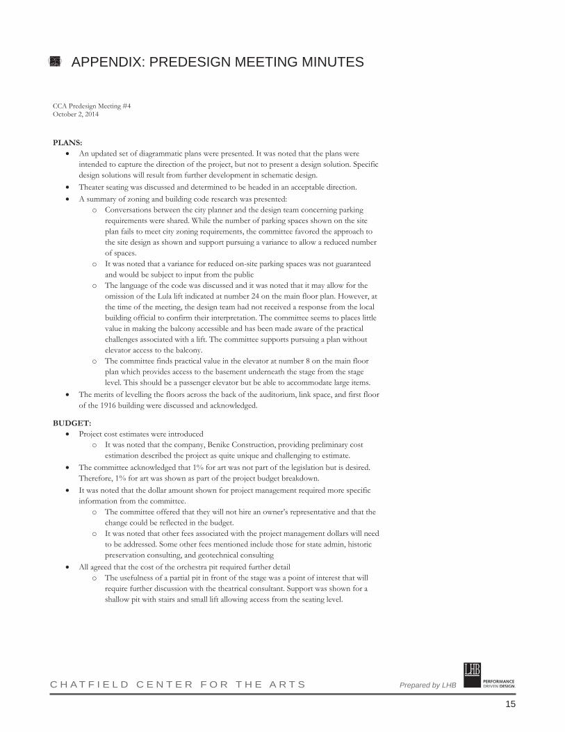
PERFORMANCE DRIVEN DESIGN.Prepared by LHB C H A T F I E L D C E N T E R F O R T H E A R T S
15
CCA Predesign Meeting #4 October 2, 2014
PLANS:
• An updated set of diagrammatic plans were presented. It was noted that the plans were intended to capture the direction of the project, but not to present a design solution. Specific design solutions will result from further development in schematic design.
• Theater seating was discussed and determined to be headed in an acceptable direction. • A summary of zoning and building code research was presented:
o Conversations between the city planner and the design team concerning parking requirements were shared. While the number of parking spaces shown on the site plan fails to meet city zoning requirements, the committee favored the approach to the site design as shown and support pursuing a variance to allow a reduced number of spaces.
o It was noted that a variance for reduced on-site parking spaces was not guaranteed and would be subject to input from the public
o The language of the code was discussed and it was noted that it may allow for the omission of the Lula lift indicated at number 24 on the main floor plan. However, at the time of the meeting, the design team had not received a response from the local building official to confirm their interpretation. The committee seems to places little value in making the balcony accessible and has been made aware of the practical challenges associated with a lift. The committee supports pursuing a plan without elevator access to the balcony.
o The committee finds practical value in the elevator at number 8 on the main floor plan which provides access to the basement underneath the stage from the stage level. This should be a passenger elevator but be able to accommodate large items.
• The merits of levelling the floors across the back of the auditorium, link space, and first floor of the 1916 building were discussed and acknowledged.
BUDGET: • Project cost estimates were introduced
o It was noted that the company, Benike Construction, providing preliminary cost estimation described the project as quite unique and challenging to estimate.
• The committee acknowledged that 1% for art was not part of the legislation but is desired. Therefore, 1% for art was shown as part of the project budget breakdown.
• It was noted that the dollar amount shown for project management required more specific information from the committee.
o The committee offered that they will not hire an owner’s representative and that the change could be reflected in the budget.
o It was noted that other fees associated with the project management dollars will need to be addressed. Some other fees mentioned include those for state admin, historic preservation consulting, and geotechnical consulting
• All agreed that the cost of the orchestra pit required further detail o The usefulness of a partial pit in front of the stage was a point of interest that will
require further discussion with the theatrical consultant. Support was shown for a shallow pit with stairs and small lift allowing access from the seating level.
APPENDIX: PREDESIGN MEETING MINUTES
PERFORMANCE DRIVEN DESIGN.Prepared by LHB C H A T F I E L D C E N T E R F O R T H E A R T S
16
CCA Predesign Meeting #4 October 2, 2014
o Sight lines and sound issues were identified as the major problem with the current arrangement.
• Two monument signs were shown as part of the budget estimate and the committee indicated that only one was needed. The committee further conveyed that the sign was part of the legislation and they had recently had some experience with another, simpler sign that was more expensive than what was indicated.
o The committee suggested that the monument sign should have an electronic LED display indicating upcoming events at the CCA
• Steve Harmon indicated that the numbers shown for mechanical and electrical cost estimates appeared to be high. However, a more complete breakdown has not been reviewed.
• The tech booth, or control room, was cited as an element that needs to be considered in the preliminary cost estimate for the predesign
• It was noted that a more detailed breakdown of the estimate numbers would aid the committee in making decisions.
• The design team noted that they will work with the consultants to provide greater clarity in the numbers where possible. It was noted that the design team had been provided with some of the estimated costs earlier that day and had not yet had the opportunity to fully review the costs with the estimator.
CLOSING: • The design team asked if there were any items not sufficiently discussed and/or diagrammed
relative to the direction of the predesign. o The committee suggested that connecting the second floor of the 1916 school to the
balcony of the auditorium was something that they were interested in. It should be noted that no drawings or diagrams produced by the design
team during the predesign to date had shown such a connection. The committee had not expressed an expectation of such a connection at the
prior predesign meetings, but indicated it had been discussed in 2009. o At the direction of the design team, all present moved to the auditorium to look at
the balcony. After discussion, the committee agreed that a connection from the 1916
school’s second floor to the auditorium was of enough interest to justify postponing the predesign submission.
The design team shall address how such a change might be incorporated in the predesign and will communicate the implications to the committee.
Robert Vogel acknowledged that entering the auditorium through a window was the only way to preserve the historic character of the space.
The tech booth, or control room, was also discussed. The possibility of formalizing the current booth’s placement was offered along with other possibilities.
It was noted that a tech booth would have to be made accessible even if other areas of the balcony were determined to be exempt
This constitutes my understanding of items discussed and decisions reached. If there are any omissions or discrepancies, please notify the author in writing. c: 140378, 304 \\lhbmspw12\projects\14Proj\140378\300 Communication\304 Minutes\140378MM100214 CCA Predesign Meeting 4.docx
APPENDIX: PREDESIGN MEETING MINUTES
___________________________________________________________________________________________________ M I N N E S O T A I O W A W I S C O N S I N
Design PhDesign PhDesign PhDesign Phaseaseasease Geotechnical ReportGeotechnical ReportGeotechnical ReportGeotechnical Report::::
Chatfield Center for the Arts Improvements
405 Main Street South
Chatfield, Minnesota
Prepared for:Prepared for:Prepared for:Prepared for:
City of Chatfield Economic Development Authority
October 8, 2014
6968.14.MNR
Chosen Valley Testing
C
V T

______________________________________________________________________________________________________ M I N N E S O T A I O W A W I S C O N S I N
Chosen Valley Testing, Inc. Geotechnical Engineering and Testing, 1410 7th Street NW, Rochester Minnesota 55901 (507) 281-0968 fax (507) 289-2523 City of Chatfield Economic Development Authority October 8, 2014 Office of the City Clerk 21 Second St SE Chatfield, MN 55923 [email protected] cc: Ms. Melissa White LHB 701 Washington Ave N, Suite 200 Minneapolis, MN 55401 [email protected]
Re: Design Phase Geotechnical Evaluation
Chatfield Center for the Arts Improvements 405 Main Street S Chatfield, Minnesota CVT Project # 6968.14.MNR
Dear Mr. Young, As authorized, we have completed the geotechnical soil borings and evaluation for the proposed improvements to the Chatfield Center for the Arts in Chatfield, Minnesota. This letter briefly summarizes the findings and analysis detailed in the attached report. Summary of Results
At the surface, the soil borings in the grass areas on the north and east sides of the existing buildings encountered about ½ to 1½ feet of topsoil, while the borings in the parking areas on the west side met approximately 2 to 3½ inches of asphalt over 4 to 8 inches of aggregate base or sand subbase. Beneath the topsoil and pavements, all of the borings encountered dark, clayey fill to depths of 5½ to 7 feet. The fill consisted primarily of sandy clay and clayey sand, mixed with some brick debris in areas. Except for the two borings closest to the building, the fill was underlain by residual soils. At most locations, this material consisted of medium to dense clayey silt with dolostone fragments (residual dolostone). On the north side of the building, the residual material was a reddish clay.

Chatfield Center for the Arts Improvements October 8, 2014 CVT Project #: 6968.14.MNR Page 2
_____________________________________________________________________________________________________ M I N N E S O T A I O W A W I S C O N S I N
All of the borings encountered harder, more intact rock at depths ranging from about 6 to 7 feet below the surface. In the two borings closest to the building, this material appeared to be present directly below the fill. In the other borings, the change was more of a transition between the residual soils and the weathered rock. The harder, weathered rock materials were mostly dolostone or a combination of dolostone and sandstone. The borings met auger refusal at depths of 8 to12 feet on materials judged to be fresher, intact dolostone bedrock. Free water was not encountered in any of the soil borings during our exploration and none of the samples returned appeared to have excess moisture. Due to the nature of the underlying rock materials, infiltrating water would be expected to seep vertically and horizontally through and along fractures or more porous zones of the rock. Summary of Analysis
As mentioned, the borings encountered clayey fill materials to depths of about 5½ to 7 feet. Most of the fill was rather dark and appears to be spoil or green area fill that was not intended for structural support. We recommend removing all fill from below the area of the addition, along with any topsoil, asphalt, and aggregate base materials or other unsuitable materials. Structural fill supporting the existing foundations can reasonably remain in place. Depending on the depth of the existing building foundation, depth of soil correction, and the proposed addition foundation elevation, sheeting or shoring may be needed to provide lateral stability to the existing foundations. The existing structure has a lower level in some areas that appears to correspond to the depth of the fill materials observed. With the understood foundation loads and implementation of the earthwork recommendations, we are of the opinion that foundations may be designed to exert bearing pressures up to 3,000 psf. The site is considered to be in an “active” karst environment and infiltrating structures is discouraged in this environment. Potential sources for ponding water should be adequately lined. We are not aware of specific plans in this regard. Remarks
We appreciate the opportunity to serve you. The attached report provides more details of our recommendations. If you have any questions about our report, please feel free to contact us at (507) 281-0968. Sincerely, Chosen Valley Testing, Inc.
Devin Ehler, EIT Colby T. Verdegan, PE Geotechnical Engineer Sr. Geotechnical/Materials Engineer
________________________________________________________________________________________________________ M I N N E S O T A I O W A W I S C O N S I N
TABL E OF CONTENTS
A. INTRODUCTION ................................................................................................................................................. 3
A.1. PURPOSE ........................................................................................................................................................... 3 A.2. SCOPE................................................................................................................................................................ 3 A.3. BORING LOCATIONS AND ELEVATIONS ............................................................................................................. 3 A.4. GEOLOGIC BACKGROUND ................................................................................................................................. 4
B. SUBSURFACE DATA ........................................................................................................................................... 4
B.1. STRATA ............................................................................................................................................................. 4 B.2. PENETRATION TEST RESULTS ............................................................................................................................ 5 B.3. GROUNDWATER DATA ...................................................................................................................................... 6
C. DESIGN DATA ...................................................................................................................................................... 6
D. ANALYSIS ............................................................................................................................................................. 6
E. BUILDING ADDITION RECOMMENDATIONS............................................................................................. 7
E.1. GENERAL GRADING RECOMMENDATIONS ......................................................................................................... 7 E.1.a. Stripping/Excavation ................................................................................................................................ 7 E.1.b. Excavation Review .................................................................................................................................... 8 E.1.c. Oversizing ................................................................................................................................................. 8 E.1.d. Filling and Compaction ............................................................................................................................ 8
E.2. BUILDING DESIGN ............................................................................................................................................. 8 E.2.a. Foundation Depth ..................................................................................................................................... 8 E.2.b. Bearing Capacity and Settlement .............................................................................................................. 8 E.2.c. Vapor Barrier and Drainage .................................................................................................................... 8 E.2.d. Slab Design: .............................................................................................................................................. 9
F. PAVEMENT RECOMMENDATIONS ............................................................................................................... 9
F.1. STRIPPING AND GRADING .................................................................................................................................. 9 F.1.a. Stripping of Paved Areas .......................................................................................................................... 9 F.1.b. Subgrade ................................................................................................................................................... 9
F.2. PAVEMENT DESIGN ............................................................................................................................................ 9
G. LOADING DOCK RETAINING WALLS .......................................................................................................... 9
H. INFILTRATION/PONDING RECOMMENDATIONS .................................................................................. 10
I. GENERAL CONSTRUCTION RECOMMENDATIONS ................................................................................ 11
I.1. DEWATERING .................................................................................................................................................... 11 I.2. EXCAVATION .................................................................................................................................................... 11 I.3. SIDESLOPES ...................................................................................................................................................... 11 I.4. COMPACTION .................................................................................................................................................... 11 I.5. COLD WEATHER ............................................................................................................................................... 11 I.6. CONSTRUCTION TESTING AND DOCUMENTATION ............................................................................................. 12
________________________________________________________________________________________________________ M I N N E S O T A I O W A W I S C O N S I N
J. LEVEL OF CARE ................................................................................................................................................ 12
K. CERTIFICATION ............................................................................................................................................... 12
APPENDIX................................................................................................................................................................. 13
KARST SURVEY SKETCH
SINKHOLE PROBABILITY SKETCH
LIDAR SKETCH
SOIL BORING LOCATION SKETCH
LOG OF BORING # 1-7
LEGEND TO SOIL DESCRIPTION

Chatfield Center for the Arts Improvements October 8, 2014 CVT Project #: 6968.14.MNR Page - 3
________________________________________________________________________________________________________ M I N N E S O T A I O W A W I S C O N S I N
Design Phase Geotechnical Report Chatfield Center for the Arts Improvements
405 Main Street S Chatfield, Minnesota
CVT Project Number: 6968.14.MNR
Date: October 8, 2014
A. Introduction
The intent of this report is to present our findings and describe the means used to collect the data. The data was collected for a specific purpose and may not be suitable for other purposes. We should be consulted before attempting to use the data for other uses. A complete and thorough review of the entire document, including its assumptions and its appendices, should be undertaken immediately upon receipt.
A.1. Purpose
This geotechnical report was prepared to aid design and construction of the proposed improvements at the Chatfield Center for the Arts in Chatfield, Minnesota. Our services were authorized by Mr. Joel Young, Chatfield City Clerk. A.2. Scope
To provide data for analysis, a total of seven penetration test borings were authorized at the site. The borings were to be drilled to depths of 15 to 25 feet or auger refusal. Our engineering scope consisted of providing geotechnical recommendations for design and construction of the proposed building addition, loading dock, and pavement replacement/expansion. A.3. Boring Locations and Elevations
The boring locations were indicated to Chosen Valley Testing on a site plan provided by the LHB. The Soil Boring Location Sketch in the Appendix shows the approximate boring locations as drilled. The sketch was created by superposing the project plan onto a satellite view of the site using GoogleEarth Software, and adding boring locations using GPS coordinates recorded in the field from a handheld device. Ground surface elevations at the borings were estimated using a laser level. Control Point 204 set by G-Cubed Engineering and Surveying was used as a benchmark, and is understood to be at elevation 1009.79 feet.
Chatfield Center for the Arts Improvements October 8, 2014 CVT Project #: 6968.14.MNR Page - 4
________________________________________________________________________________________________________ M I N N E S O T A I O W A W I S C O N S I N
A.4. Geologic Background
A geotechnical report is based on subsurface data collected for the specific structure or problem. Available geologic data from the region can help interpretation of the data and is briefly summarized in this section. Geologic maps suggest that the natural upper soil in the area primarily consists of shallow bedrock within 5 feet of the surface and often overlain by residual soils derived from weathered bedrock. Bedrock is commonly dolomite, sandstone, and some shale of the Shakopee Formation.
B. Subsurface Data
The borings were performed using penetration test procedures (Method of Test D1586 of the American Society for Testing and Materials). This procedure allows for the extraction of intact soil specimen from deep in the ground. With this method, a hollow-stem auger is drilled to the desired sampling depth. A 2-inch OD sampling tube is then screwed onto the end of a sampling rod, inserted through the hole in the auger's tip, and then driven into the soil with a 140-pound hammer dropped repeatedly from a height of 30 inches above the sampling rod. The sampler is driven 18 inches into the soil, unless the material is too hard. The samples are generally taken at 2½ to 5-foot intervals. The core of soil obtained was classified and logged by our drilling personnel at the site and a representative portion was then sealed and delivered to our laboratory for further review. B.1. Strata
At the surface, the soil borings in the grass areas on the north and east sides of the existing buildings encountered about ½ to 1½ feet of topsoil, while the borings in the parking areas on the west side met approximately 2 to 3½ inches of asphalt over 4 to 8 inches of aggregate base or sand subbase. Beneath the topsoil and pavements, all of the borings encountered dark, clayey fill to depths of 5½ to 7 feet. The fill consisted primarily of sandy clay and clayey sand, mixed with some brick debris in areas. Except for the two borings closest to the building (Borings B-6 and B-7), the fill was underlain by residual soils. At most locations, this material consisted of medium to dense clayey silt with dolostone fragments (residual dolostone). On the north side of the building (Boring B-2), the residual material was a reddish clay. All of the borings encountered harder, more intact rock at depths ranging from about 6 to 7 feet below the surface. In the two borings closest to the building, this material appeared to be present directly below the fill. In the other borings, the change was more of a transition between the residual soils and the weathered rock. The harder, weathered rock materials were mostly dolostone or a combination of dolostone and sandstone. The borings met auger refusal at depths of 8 to12 feet on materials judged to be fresher, intact dolostone bedrock.
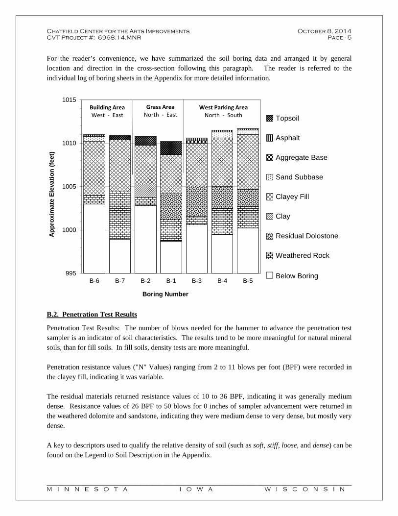
Chatfield Center for the Arts Improvements October 8, 2014 CVT Project #: 6968.14.MNR Page - 5
________________________________________________________________________________________________________ M I N N E S O T A I O W A W I S C O N S I N
For the reader’s convenience, we have summarized the soil boring data and arranged it by general location and direction in the cross-section following this paragraph. The reader is referred to the individual log of boring sheets in the Appendix for more detailed information.
B.2. Penetration Test Results
Penetration Test Results: The number of blows needed for the hammer to advance the penetration test sampler is an indicator of soil characteristics. The results tend to be more meaningful for natural mineral soils, than for fill soils. In fill soils, density tests are more meaningful. Penetration resistance values ("N" Values) ranging from 2 to 11 blows per foot (BPF) were recorded in the clayey fill, indicating it was variable. The residual materials returned resistance values of 10 to 36 BPF, indicating it was generally medium dense. Resistance values of 26 BPF to 50 blows for 0 inches of sampler advancement were returned in the weathered dolomite and sandstone, indicating they were medium dense to very dense, but mostly very dense. A key to descriptors used to qualify the relative density of soil (such as soft, stiff, loose, and dense) can be found on the Legend to Soil Description in the Appendix.
995
1000
1005
1010
1015
B-6 B-7 B-2 B-1 B-3 B-4 B-5
Ap
pro
xim
ate
Ele
vati
on
(fe
et)
Boring Number
Topsoil
Asphalt
Aggregate Base
Sand Subbase
Clayey Fill
Clay
Residual Dolostone
Weathered Rock
Below Boring
Building AreaWest - East
West Parking AreaNorth - South
Grass AreaNorth - East
Below Boring

Chatfield Center for the Arts Improvements October 8, 2014 CVT Project #: 6968.14.MNR Page - 6
________________________________________________________________________________________________________ M I N N E S O T A I O W A W I S C O N S I N
B.3. Groundwater Data
During drilling, the drillers may note the presence of moisture on the sampler, in the cuttings, or in the borehole itself. These findings are reported on the Logs of Boring. Because water levels vary with weather, time of year, and other factors, the presence or lack of water during exploration is subject to interpretation and is not always conclusive.
Free water was not encountered in any of the soil borings during our exploration and none of the samples returned appeared to have excess moisture. Due to the nature of the underlying rock materials, infiltrating water would be expected to seep vertically and horizontally through and along fractures or more porous zones of the rock.
C. Design Data
It is understood that a new two-story connecting link is planned to be constructed between the old school and Potter Auditorium buildings, with conventional frost depth spread footings, cast-in-place concrete foundations, cmu/brick cavity and curtain wall exterior bearing walls, and steel bar joist roof. We assume this addition will be slab-on-grade. Interior bearing is understood to consist of a combination of steel beam/column lines with concrete spread footings, and cmu bearing/shear walls where needed. Preliminary design information indicated that column loads are anticipated to be in the range of approximately 50 to 150 kips, and wall loads are anticipated to be in the range of approximately 2 to 5 kips/ft. Other site improvements are understood to consist of a loading dock at the southwest side of the existing auditorium, replacement and expansion of the existing parking lot, and new sidewalks.
D. Analysis
As mentioned, the borings encountered clayey fill materials to depths of about 5½ to 7 feet. Most of the fill was rather dark and appears to be spoil or green area fill that was not intended for structural support. We recommend removing all fill from below the area of the addition, along with any topsoil, asphalt, and aggregate base materials or other unsuitable materials. Structural fill supporting the existing foundations can reasonably remain in place. Depending on the depth of the existing building foundation, depth of soil correction, and the proposed addition foundation elevation, sheeting or shoring may be needed to provide lateral stability to the existing foundations. The existing structure has a lower level in some areas that appears to correspond to the depth of the fill materials observed. We recommend that geotechnical personnel from Chosen Valley Testing be on hand during excavations in order to evaluate the suitability of the bearing soils and their consistency with our expectations based on the soil boring data, analyses, and recommendations stated above.

Chatfield Center for the Arts Improvements October 8, 2014 CVT Project #: 6968.14.MNR Page - 7
________________________________________________________________________________________________________ M I N N E S O T A I O W A W I S C O N S I N
With the understood foundation loads and implementation of the earthwork recommendations, we are of the opinion that foundations may be designed to exert bearing pressures up to 3,000 psf. Traffic loading information was not provided. Pavement subgrades are expected to mainly consist of sandy lean clay and clayey sand. These soils have R-values ranging from 10 to 20, CBR values ranging from less than 5 to 40, and modulus of subgrade reactions (K) of 75 to 200 pounds per cubic inch (pci). We recommend using an R-value of 12, CBR value of 5, and modulus of subgrade reaction of 100 pci for pavement design. The site is considered to be in an “active” karst environment and infiltrating structures are discouraged in this environment. Potential sources for ponding water should be adequately lined. We are not aware of specific plans in this regard. The remainder of this report provides further details of our recommendations for the proposed improvements.
E. Building Addition Recommendations
E.1. General Grading Recommendations
E.1.a. Stripping/Excavation: The clay fill materials are unsuitable for support and should be completely removed from below the building and oversize areas. Prior to excavating, the topsoil, asphalt, and aggregate base materials should be stripped and removed from the site. The following table shows the apparent depth and elevation of the unsuitable materials at the two boring locations associated with the building addition, and includes the assumed footing elevations.
Boring Locations
Approx. Ground Surface Elevation
(Feet)
Approx. Depth of Unsuitable Materials
(Feet)
Approx. Elevation to Bottom of Unsuitable
Materials (Feet)
Assumed Bottom of Footing Elevation
(Feet)
B-6 1011 7 1004 1007 ½
B-7 1011 6 ½ 1004 ½ 1007 ½
Structural fill supporting the existing foundations can reasonably remain in place. Depending on the depth of the existing building foundation, depth of soil correction, and the proposed addition foundation elevation, sheeting or shoring may be needed to provide lateral stability to the existing foundations. Some of the existing footings are below frost depth, and new footings should be stepped down as needed to prevent lateral loads on the existing foundation walls.

Chatfield Center for the Arts Improvements October 8, 2014 CVT Project #: 6968.14.MNR Page - 8
________________________________________________________________________________________________________ M I N N E S O T A I O W A W I S C O N S I N
E.1.b. Excavation Review: We recommend that Chosen Valley Testng Personnell be retained to evaluate the suitability of the bearing soils and their consistency with our expectation based on the soil boring data, Analysis, and recommendations in this report. E.1.c. Oversizing: Any corrective excavations should be oversized horizontally at least 1 foot beyond the foundations for each foot of fill needed below footing grade. This oversizing can be reduced by up to 50% if rather precise staking is present during grading and the excavation limits can be rather precisely confirmed relative to the foundations. E.1.d. Filling and Compaction: All fill should be compacted to a minimum of 95% of its maximum standard Proctor density (ASTM D 698). For ease in compaction, we recommend using imported sand or gravel having less than 12% particles passing a number 200 sieve, as engineered structural fill. Aggregate base, limestone screenings, or similar materials could also be considered for use as fill, but will require more stringent moisture control during compaction – but would still result in a higher risk of post construction movement. The existing clay fill or similar fine grained soils are not recommended in this application and should be placed in green areas outside of the support zone for the slabs and foundations. Clayey materials should also not be used against basement walls. For slabs with coverings that are less permeable than concrete, we recommend using free-draining sands having less than 5% particles passing a number 200 sieve in the upper 4 to 6 inches of the subgrade. E.2. Building Design
E.2.a. Foundation Depth: For frost protection, we recommend that exterior foundations for heated structures bear on soils at least 42 inches below the exposed ground surface. Interior footings for heated structures can be placed directly below slabs. Footings for unheated structures should be placed at least 60 inches below the surface. E.2.b. Bearing Capacity and Settlement: With the understood foundation loads and implementation of the earthwork recommendations, we are of the opinion that foundations may be designed to exert bearing pressures up to 3,000 psf. This capacity includes a safety factor of at least 3 against shear failure. Based on the recommended bearing pressure, total settlement of footings is expected to be on the order of 1 inch or less. Differential settlement is expected to be on the order of ½ inch or less between similarly loaded footings. E.2.c. Vapor Barrier and Drainage: A vapor barrier is recommended below slabs that will receive floor coverings. Any partial sections of vapor barrier should be taped together for the entire length of the seam, to reduce the risk of moisture collecting above the vapor barrier. Some contractors prefer to place this below a layer of sand, to reduce the potential for curling.

Chatfield Center for the Arts Improvements October 8, 2014 CVT Project #: 6968.14.MNR Page - 9
________________________________________________________________________________________________________ M I N N E S O T A I O W A W I S C O N S I N
E.2.d. Slab Design: The completed slab subgrade is assumed to consist of sand fill over residual soils or weathered limestone. We recommend using a modulus of subgrade reaction of up to 200 pounds per cubic inch (pci) for these conditions.
F. Pavement Recommendations
F.1. Stripping and Grading
F.1.a. Stripping of Paved Areas: The surface materials at the site generally consisted of about ½ to 1½ feet of topsoil in green areas. The existing pavements consisted of about 2 to 3½ inches of asphalt over 4 to 8 inches of aggregate base or sand subbase. We recommend stripping and removing any topsoil and existing pavement sections before placing any new pavements. With proper milling, it should be possible to reuse the paving materials as the aggregate portion of newly paved areas. The topsoil should be discarded or used as needed in green areas or discarded off site. F.1.b. Subgrade: Based on the soil boring data, subgrades are expected to mainly consist of sandy lean clay and clayey sand. To further promote uniformity, we recommend scarifying, drying if needed, and compacting the near-surface soils before placing pavements. Soils placed below the paved areas should be compacted to 100% of their standard Proctor density (ASTM D 698) in the upper 3 feet and to at least 95% below. Depending on the materials used as fill, compaction test results may be difficult to quantify because of difficulties of obtaining a representative Proctor test on the mixed materials present. At a minimum, ordinary compactive efforts should be implemented and subgrades should be capable of passing a proof roll test with a fully loaded tandem axle truck. F.2. Pavement Design
As stated previously, subgrades are expected to mainly consist of sandy lean clay and clayey sand. We recommend using an R-value of 10, CBR value of 5, or a modulus of subgrade reaction of 100 pci for pavement design on these materials.
G. Loading Dock Retaining Walls
Lateral support values are provided for design of below-grade walls. Backfill should be compacted to at least 95% of its maximum standard Proctor density (ASTM D 698). Lateral resistance will depend on the materials used. We recommend using clean sands, having less than 10% fines, as fill against below-grade walls. The following table includes support values for the recommended clean sands, except for the coefficient of friction between concrete and soil. That value is based on the assumption that footings in that area may bear on the natural soils below the replacement sand fill, due to the basement structure at the existing building in that area. These values do not include a safety factor.
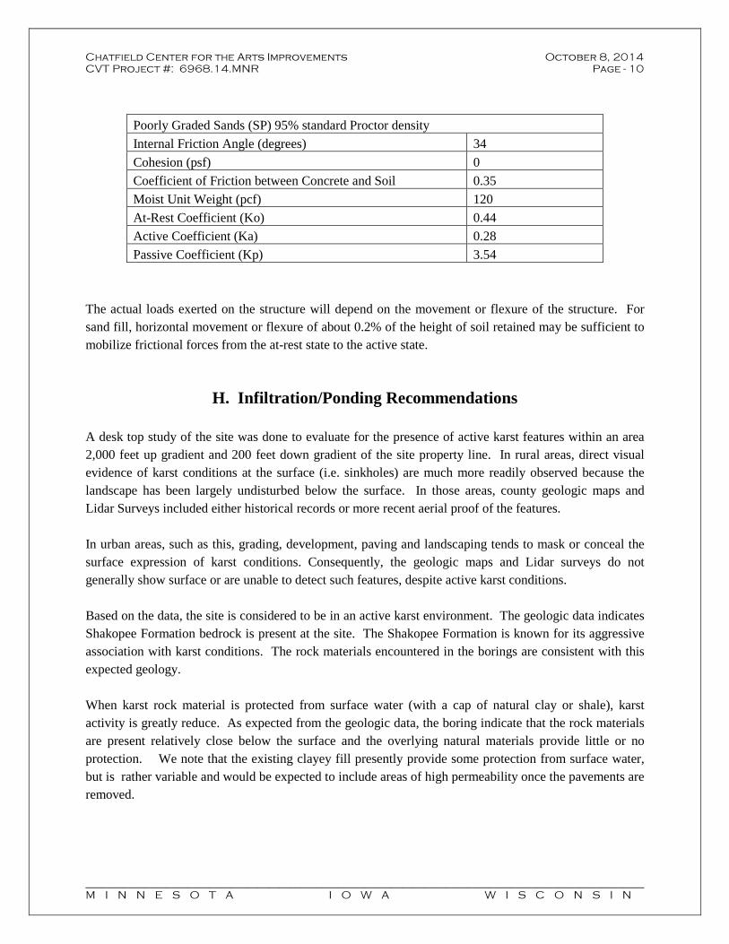
Chatfield Center for the Arts Improvements October 8, 2014 CVT Project #: 6968.14.MNR Page - 10
________________________________________________________________________________________________________ M I N N E S O T A I O W A W I S C O N S I N
Poorly Graded Sands (SP) 95% standard Proctor density
Internal Friction Angle (degrees) 34
Cohesion (psf) 0
Coefficient of Friction between Concrete and Soil 0.35
Moist Unit Weight (pcf) 120
At-Rest Coefficient (Ko) 0.44
Active Coefficient (Ka) 0.28
Passive Coefficient (Kp) 3.54
The actual loads exerted on the structure will depend on the movement or flexure of the structure. For sand fill, horizontal movement or flexure of about 0.2% of the height of soil retained may be sufficient to mobilize frictional forces from the at-rest state to the active state.
H. Infiltration/Ponding Recommendations
A desk top study of the site was done to evaluate for the presence of active karst features within an area 2,000 feet up gradient and 200 feet down gradient of the site property line. In rural areas, direct visual evidence of karst conditions at the surface (i.e. sinkholes) are much more readily observed because the landscape has been largely undisturbed below the surface. In those areas, county geologic maps and Lidar Surveys included either historical records or more recent aerial proof of the features. In urban areas, such as this, grading, development, paving and landscaping tends to mask or conceal the surface expression of karst conditions. Consequently, the geologic maps and Lidar surveys do not generally show surface or are unable to detect such features, despite active karst conditions. Based on the data, the site is considered to be in an active karst environment. The geologic data indicates Shakopee Formation bedrock is present at the site. The Shakopee Formation is known for its aggressive association with karst conditions. The rock materials encountered in the borings are consistent with this expected geology. When karst rock material is protected from surface water (with a cap of natural clay or shale), karst activity is greatly reduce. As expected from the geologic data, the boring indicate that the rock materials are present relatively close below the surface and the overlying natural materials provide little or no protection. We note that the existing clayey fill presently provide some protection from surface water, but is rather variable and would be expected to include areas of high permeability once the pavements are removed.
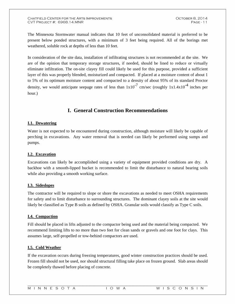
Chatfield Center for the Arts Improvements October 8, 2014 CVT Project #: 6968.14.MNR Page - 11
________________________________________________________________________________________________________ M I N N E S O T A I O W A W I S C O N S I N
The Minnesota Stormwater manual indicates that 10 feet of unconsolidated material is preferred to be present below ponded structures, with a minimum of 3 feet being required. All of the borings met weathered, soluble rock at depths of less than 10 feet. In consideration of the site data, installation of infiltrating structures is not recommended at the site. We are of the opinion that temporary storage structures, if needed, should be lined to reduce or virtually eliminate infiltration. The on-site clayey fill could likely be used for this purpose, provided a sufficient layer of this was properly blended, moisturized and compacted. If placed at a moisture content of about 1 to 5% of its optimum moisture content and compacted to a density of about 95% of its standard Proctor
density, we would anticipate seepage rates of less than 1x10⁻⁷ cm/sec (roughly 1x1.4x10-4 inches per
hour.)
I. General Construction Recommendations
I.1. Dewatering
Water is not expected to be encountered during construction, although moisture will likely be capable of perching in excavations. Any water removal that is needed can likely be performed using sumps and pumps. I.2. Excavation
Excavations can likely be accomplished using a variety of equipment provided conditions are dry. A backhoe with a smooth-lipped bucket is recommended to limit the disturbance to natural bearing soils while also providing a smooth working surface. I.3. Sideslopes
The contractor will be required to slope or shore the excavations as needed to meet OSHA requirements for safety and to limit disturbance to surrounding structures. The dominant clayey soils at the site would likely be classified as Type B soils as defined by OSHA. Granular soils would classify as Type C soils. I.4. Compaction
Fill should be placed in lifts adjusted to the compactor being used and the material being compacted. We recommend limiting lifts to no more than two feet for clean sands or gravels and one foot for clays. This assumes large, self-propelled or tow-behind compactors are used. I.5. Cold Weather
If the excavation occurs during freezing temperatures, good winter construction practices should be used. Frozen fill should not be used, nor should structural filling take place on frozen ground. Slab areas should be completely thawed before placing of concrete.

Chatfield Center for the Arts Improvements October 8, 2014 CVT Project #: 6968.14.MNR Page - 12
________________________________________________________________________________________________________ M I N N E S O T A I O W A W I S C O N S I N
I.6. Construction Testing and Documentation
The bottom of all excavations should be evaluated and documented by geotechnical personnel before placing fill or foundations. Fill placed below building and pavement areas should be evaluated for conformance to the project gradation recommendations and should be tested for compaction. If the filling proceeds during periods of freezing weather, full-time testing should be considered to help confirm that imported fill is thawed prior to and during compaction, and that all snow has been removed before placement of the fill. Although our firm offers testing services relating to civil and structural components of the building (such as concrete testing, reinforcement observations, etc.) specification of such services is beyond our work scope and the designer should be consulted as to such requirements.
J. Level of Care
The services provided for this project have been conducted in a manner consistent with the level of care and skill ordinarily exercised by members of the profession currently practicing in this area, under similar budget and time constraints. This is our professional responsibility. No other warranty, expressed or implied, is made.
K. Certification
I hereby certify that this report was prepared by me, or under my direct supervision, and that I am a duly licensed engineer under the laws of the State of Minnesota.
Colby T. Verdegan, PE Registration Number 018983 October 8, 2014

Chatfield Center for the Arts Improvements October 8, 2014 CVT Project #: 6968.14.MNR Page - 13
________________________________________________________________________________________________________ M I N N E S O T A I O W A W I S C O N S I N
Appendix
Karst Survey Sketch
Sinkhole Probability Sketch
LiDAR Sketch
Soil Boring Location Sketch
Log of Boring # 1-7
Legend to Soil Description

1018
1020
1016
1022
1024
1026
1028
1030
1032
1014
1034
1036
1038
1012
1040
1042
1044
1046
1048
1050
1052
1054
1056
1058
1060
1062
1064
1010
1066
1068
1070
1072
1074
1008
1076
1078
1110
108 0
1112
1114
1082
1116
1100
1118
1084
1102
1104
1086
1106
1088
1108
1090
1092
1094
1006
1120
1122
1124
1126
1128
1130
1132
1134
1136
1138
1140
1142
1144
1146
1148 1150 1152 1154
1156
1158 1160
1162
1164
11661168
1170
1172
1174
11761178 11801182
1184
1186
1188
1190 1192
1194
11961198
1200
1 20 2
120
412
06
1208
1210
1212
1214
1216 1218
1220
1222
1224
998
1004
996
1002
994 992
99098
8
1000
1226
970
968
1228
1010
1030
1010
998
996
1030
1004
1 050
1000
1000
1008
1010
998
1156
1008
1008
1004
1012
1008
1032
996
1006 10
12
1218
1022
1016
988
1008
1018
1016
1000
1018
1156
1006992
1018
1020
998
1082
1008
1008
1014
1012
1000
1164
1010
1014
1002
1008
1158
1028
1008
1218
1012
1024
994
Karst Survey SketchChatfield Center for the Arts Improvements
405 Main St SChatfield, MN6968.14.MNR
¯Legend
Project Area
Area of Desktop Study
Published Karst Features
D
Spring/Seep
Y Stream Sinks
# Sinkhole
contours
C Chosen Valley Testing, Inc.
V T
MnGeo WMS service (aerial photography): 2011 Aerial Photo
* None Found
* None Found
* None Found
0 1,000 2,000500 Feet
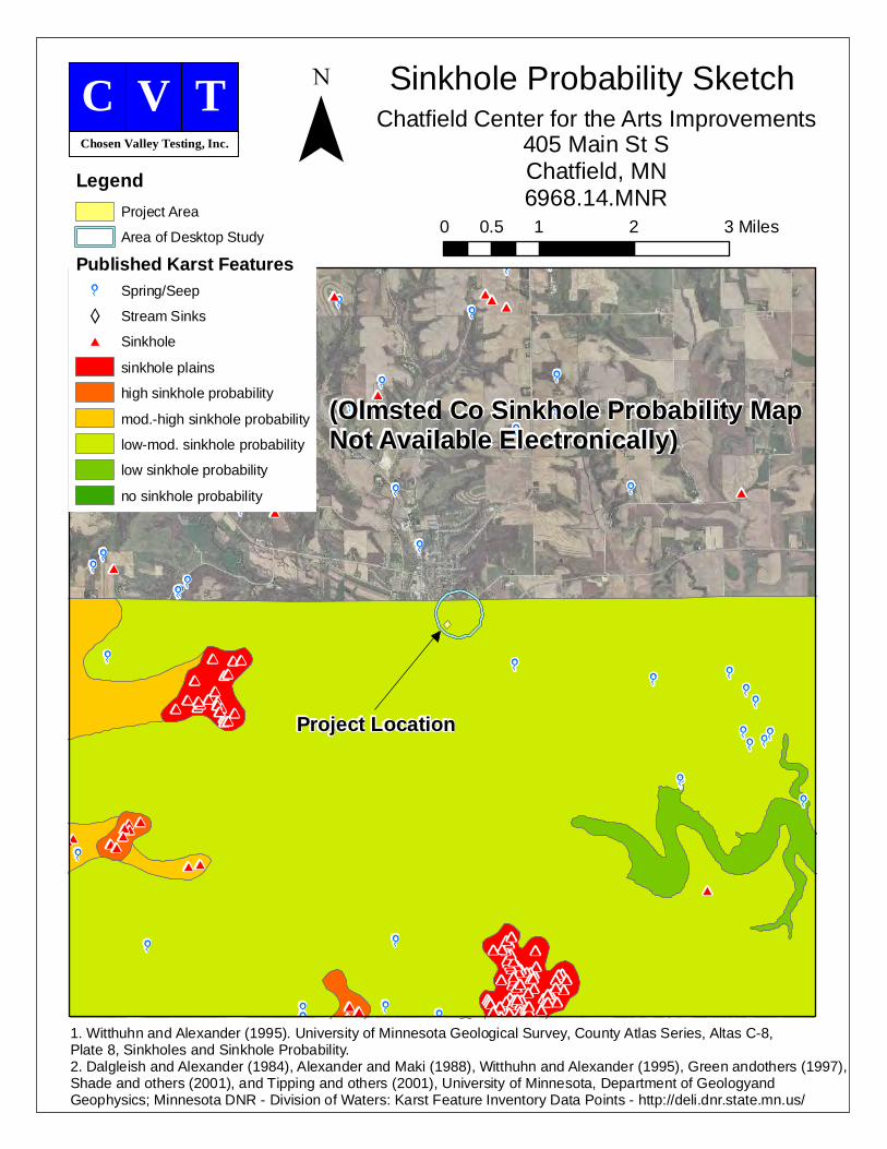
D
D
D
DD
DD
D
D
D
D
DDD
D
D
D
D
D
DD
D
#
#
###
###
#
########
#############
#
#
### ##
#
##
######
###
##
#
######
#
#
#
#
###
#
#
#
##
##
#
###
##### ##
###
#
###
##
#
#
#
#
#
##
#####
D
D
DDDDD D
D
D
D
D
D
D
D
DD
D
D
D
D
DD
D
D
D D D DD
D
D
D
D
D
D D
D
#
#
#
#
##
##
#
###
#
#
##
Sinkhole Probability SketchChatfield Center for the Arts Improvements
405 Main St SChatfield, MN6968.14.MNR
¯Legend
Project Area
Area of Desktop Study
Published Karst Features
D
Spring/Seep
Y Stream Sinks
# Sinkhole
sinkhole plains
high sinkhole probability
mod.-high sinkhole probability
low-mod. sinkhole probability
low sinkhole probability
no sinkhole probability
C Chosen Valley Testing, Inc.
V T
1. Witthuhn and Alexander (1995). University of Minnesota Geological Survey, County Atlas Series, Altas C-8, Plate 8, Sinkholes and Sinkhole Probability.2. Dalgleish and Alexander (1984), Alexander and Maki (1988), Witthuhn and Alexander (1995), Green andothers (1997), Shade and others (2001), and Tipping and others (2001), University of Minnesota, Department of Geologyand Geophysics; Minnesota DNR - Division of Waters: Karst Feature Inventory Data Points - http://deli.dnr.state.mn.us/
0 1 2 30.5 Miles
Project Location
(Olmsted Co Sinkhole Probability Map Not Available Electronically)

LiDAR SketchChatfield Center for the Arts Improvements
405 Main St SChatfield, MN6968.14.MNR
¯Legend
Project Area
Area of Desktop Study
Published Karst Features
D
Spring/Seep
Y Stream Sinks
# Sinkhole
C Chosen Valley Testing, Inc.
V T
DEM01HS - Hillshade of DEM01, November 18-24, 2008;Minnesota Geospatial Information Office; http://www.mngeo.state.mn.us/committee/standards/mgmg/metadata.htm
* None Found
* None Found
* None Found
0 1,000 2,000500 Feet

N
Soil Boring Location Sketch Chatfield Center for the Arts Improvements
405 Main Street S
Chatfield, Minnesota
6968.14.MNR
C Chosen Valley Testing, Inc.
V T
Legend
Boring Locations
Benchmark
B-6
B-1
B-2
B-4
B-3
B-7
B-5
BM
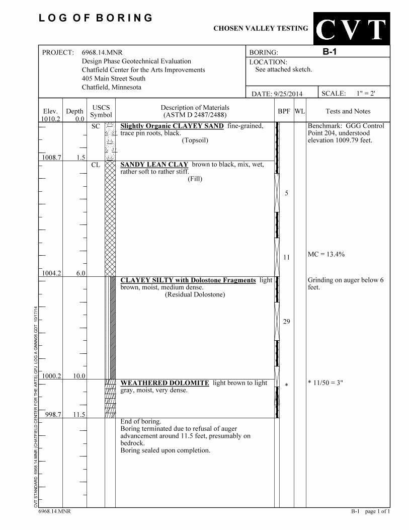
1004.2
End of boring.Boring terminated due to refusal of augeradvancement around 11.5 feet, presumably onbedrock.Boring sealed upon completion.
* 11/50 = 3"
1.5
6.0
10.0
11.5
MC = 13.4%
Benchmark: GGG ControlPoint 204, understoodelevation 1009.79 feet.
CVT S
TAND
ARD
6968
.14.M
NR (C
HATF
IELD
CENT
ER FO
R TH
E ART
S).G
PJ L
OG A
GNNN
06.G
DT 1
0/17/1
4
998.7
Slightly Organic CLAYEY SAND fine-grained,trace pin roots, black.
(Topsoil)
SANDY LEAN CLAY brown to black, mix, wet,rather soft to rather stiff.
(Fill)
CLAYEY SILTY with Dolostone Fragments lightbrown, moist, medium dense.
(Residual Dolostone)
WEATHERED DOLOMITE light brown to lightgray, moist, very dense. *
5
Grinding on auger below 6feet.
29
1000.2
SC
CL
11
6968.14.MNRDesign Phase Geotechnical EvaluationChatfield Center for the Arts Improvements405 Main Street SouthChatfield, Minnesota
See attached sketch.LOCATION:
WLUSCSSymbol Tests and Notes
1008.7
Elev.
DATE: 9/25/2014Description of Materials(ASTM D 2487/2488)Depth
B-1 page 1 of 1
BPF0.0
BORING: B-1
6968.14.MNR
1010.2
SCALE: 1" = 2'
CHOSEN VALLEY TESTINGL O G O F B O R I N G
PROJECT:
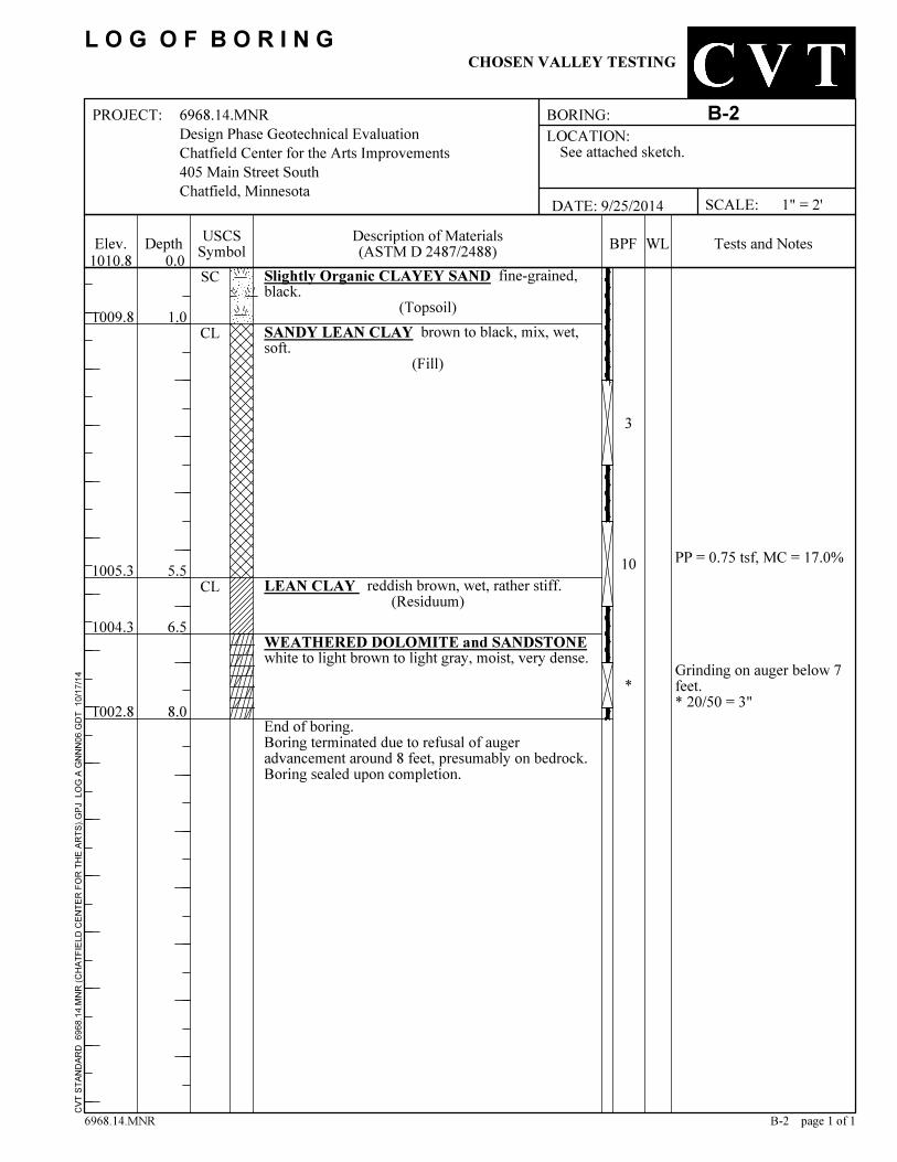
1002.8
5.5
6.5
8.0
1009.8
* 20/50 = 3"
1004.3
Grinding on auger below 7feet.
CVT S
TAND
ARD
6968
.14.M
NR (C
HATF
IELD
CENT
ER FO
R TH
E ART
S).G
PJ L
OG A
GNNN
06.G
DT 1
0/17/1
4
Slightly Organic CLAYEY SAND fine-grained,black.
(Topsoil)SANDY LEAN CLAY brown to black, mix, wet,soft.
(Fill)
LEAN CLAY reddish brown, wet, rather stiff.(Residuum)
WEATHERED DOLOMITE and SANDSTONEwhite to light brown to light gray, moist, very dense.
End of boring.Boring terminated due to refusal of augeradvancement around 8 feet, presumably on bedrock.Boring sealed upon completion.
1005.3
3
10
*
1.0
SC
CL
CLPP = 0.75 tsf, MC = 17.0%
See attached sketch.LOCATION:
WLUSCSSymbol Tests and NotesDepth
6968.14.MNRDesign Phase Geotechnical EvaluationChatfield Center for the Arts Improvements405 Main Street SouthChatfield, Minnesota
Elev.
DATE: 9/25/2014Description of Materials(ASTM D 2487/2488)
BORING: B-2
6968.14.MNR B-2 page 1 of 1
0.0
PROJECT:
1010.8
L O G O F B O R I N GCHOSEN VALLEY TESTING
SCALE: 1" = 2'
BPF

CLAYEY SILT with Dolostone Fragments lightbrown, moist, medium dense.
(Residual Dolostone)
0.6
5.5
9.0
10.0 * 50 = 2" (set)
1010.0
Grinding on auger below 6feet.
1001.6
CVT S
TAND
ARD
6968
.14.M
NR (C
HATF
IELD
CENT
ER FO
R TH
E ART
S).G
PJ L
OG A
GNNN
06.G
DT 1
0/17/1
4
3.5" ASPHALT4" AGGREGATE BASESANDY LEAN CLAY trace brick debris, black,wet, medium.
(Fill)
1010.3
8
11
27
0.3
1000.6
CL
MC = 15.0%
*
6968.14.MNRDesign Phase Geotechnical EvaluationChatfield Center for the Arts Improvements405 Main Street SouthChatfield, Minnesota
See attached sketch.LOCATION:
WL
WEATHERED DOLOMITE and SANDSTONE trace seams of shale, white to light gray to lightbrown, moist, very dense.
1005.1
Tests and NotesBPFUSCSSymbolElev.
DATE: 9/25/2014Description of Materials(ASTM D 2487/2488)Depth
B-3
SCALE: 1" = 2'
B-3 page 1 of 1
0.0
BORING:
6968.14.MNR
End of boring.Boring terminated due to refusal of augeradvancement around 10 feet, presumably onbedrock.Boring sealed upon completion.
CHOSEN VALLEY TESTINGL O G O F B O R I N G
1010.6
PROJECT:
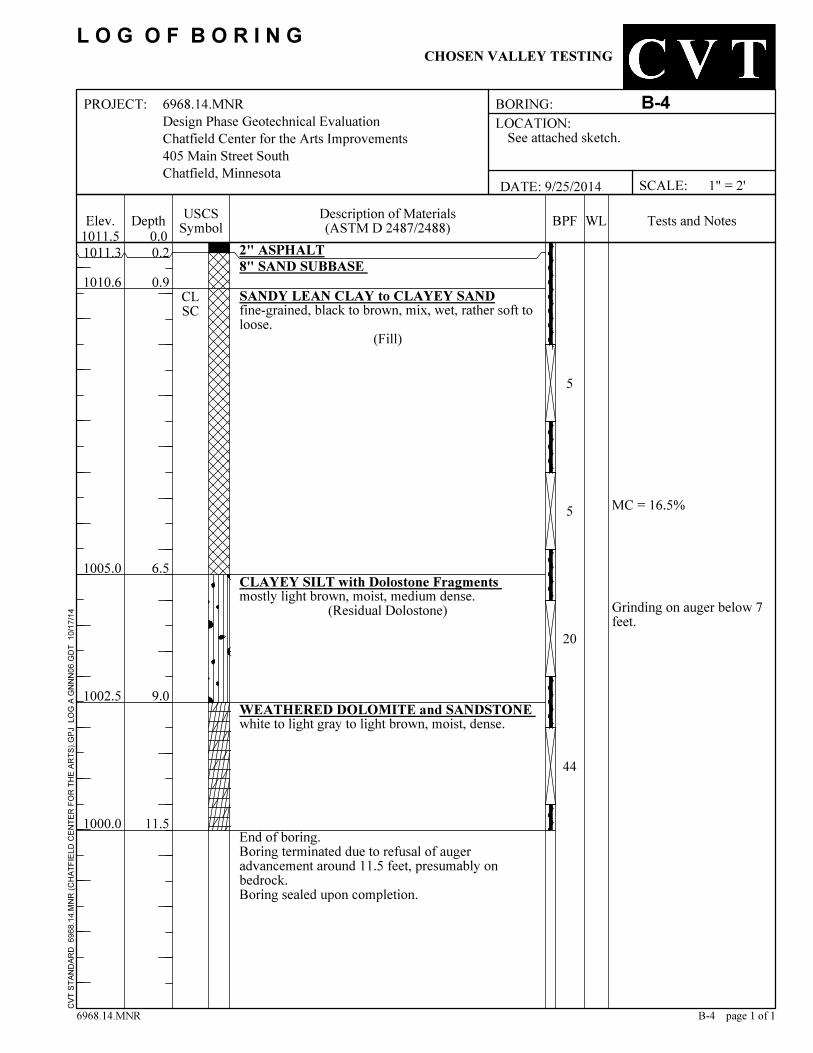
1005.0CLAYEY SILT with Dolostone Fragments mostly light brown, moist, medium dense.
(Residual Dolostone)
0.9
6.5
9.0
11.5
Grinding on auger below 7feet.
MC = 16.5%
CVT S
TAND
ARD
6968
.14.M
NR (C
HATF
IELD
CENT
ER FO
R TH
E ART
S).G
PJ L
OG A
GNNN
06.G
DT 1
0/17/1
4
1000.0
2" ASPHALT8" SAND SUBBASE SANDY LEAN CLAY to CLAYEY SANDfine-grained, black to brown, mix, wet, rather soft toloose.
(Fill)
1011.3
5
5
0.2
44
1002.5
CLSC
20
6968.14.MNRDesign Phase Geotechnical EvaluationChatfield Center for the Arts Improvements405 Main Street SouthChatfield, Minnesota
See attached sketch.LOCATION:
WL
WEATHERED DOLOMITE and SANDSTONE white to light gray to light brown, moist, dense.
1010.6
Tests and NotesBPFUSCSSymbolElev.
DATE: 9/25/2014Description of Materials(ASTM D 2487/2488)Depth
SCALE: 1" = 2'
B-4 page 1 of 1
0.0
B-4
6968.14.MNR
PROJECT:
End of boring.Boring terminated due to refusal of augeradvancement around 11.5 feet, presumably onbedrock.Boring sealed upon completion.
CHOSEN VALLEY TESTING
BORING:
1011.5
L O G O F B O R I N G
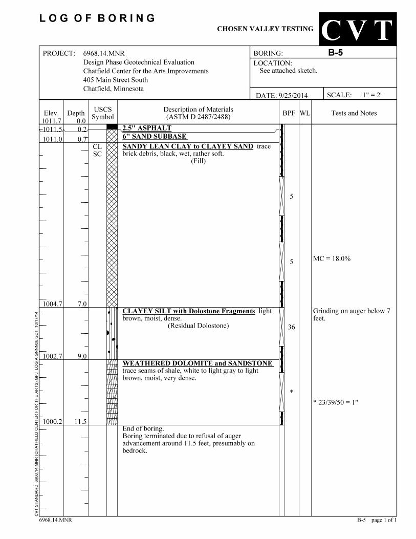
1004.7
0.20.7
7.0
9.0
11.5
CLAYEY SILT with Dolostone Fragments lightbrown, moist, dense.
(Residual Dolostone)
MC = 18.0%
CVT S
TAND
ARD
6968
.14.M
NR (C
HATF
IELD
CENT
ER FO
R TH
E ART
S).G
PJ L
OG A
GNNN
06.G
DT 1
0/17/1
4
1000.2
2.5" ASPHALT6" SAND SUBBASE SANDY LEAN CLAY to CLAYEY SAND tracebrick debris, black, wet, rather soft.
(Fill)
1011.5
5
5
* 23/39/50 = 1"*
Grinding on auger below 7feet.
CLSC
1002.7
36
6968.14.MNRDesign Phase Geotechnical EvaluationChatfield Center for the Arts Improvements405 Main Street SouthChatfield, Minnesota
See attached sketch.LOCATION:
WL
WEATHERED DOLOMITE and SANDSTONE trace seams of shale, white to light gray to lightbrown, moist, very dense.
1011.0
Tests and NotesBPFUSCSSymbolElev.
DATE: 9/25/2014Description of Materials(ASTM D 2487/2488)Depth
SCALE: 1" = 2'
B-5 page 1 of 1
0.0
B-5
6968.14.MNR
PROJECT:
End of boring.Boring terminated due to refusal of augeradvancement around 11.5 feet, presumably onbedrock.
CHOSEN VALLEY TESTING
BORING:
1011.7
L O G O F B O R I N G

8.0
1010.81010.2
1004.0
0.2
CVT S
TAND
ARD
6968
.14.M
NR (C
HATF
IELD
CENT
ER FO
R TH
E ART
S).G
PJ L
OG A
GNNN
06.G
DT 1
0/17/1
4
8" SAND SUBBASESANDY LEAN CLAY to CLAYEY SAND blackto brown to gray, mix, wet, soft to rather soft.
(Fill)
WEATHERED DOLOMITE with seams of LeanClay, white to light brown to light gray, moist, verydense.End of boring.Boring terminated due to refusal of augeradvancement around 8 feet, presumably on bedrock.Boring sealed upon completion.
1003.0
2
4
*7.0
0.8CL
MC = 14.1%
* 50 = 0" (set)Grinding on auger at 7.5feet.
2" ASPHALT
See attached sketch.LOCATION:
WLUSCSSymbol Tests and Notes
6968.14.MNRDesign Phase Geotechnical EvaluationChatfield Center for the Arts Improvements405 Main Street SouthChatfield, Minnesota
Elev.
DATE: 9/25/2014Description of Materials(ASTM D 2487/2488)
6968.14.MNR B-6 page 1 of 1
0.0Depth
B-6PROJECT: BORING:
CHOSEN VALLEY TESTING
SCALE: 1" = 2'
1011.0BPF
L O G O F B O R I N G

WEATHERED DOLOMITE light brown to lightgray, moist, very dense.
Grinding on auger below8.5 feet.
* 50 = 0" (set)
0.5
6.5
8.5
12.0
Poor Sample Return
1004.4
CVT S
TAND
ARD
6968
.14.M
NR (C
HATF
IELD
CENT
ER FO
R TH
E ART
S).G
PJ L
OG A
GNNN
06.G
DT 1
0/17/1
4
998.9
Slightly Organic LEAN CLAY trace pin roots,black.
(Topsoil)SANDY LEAN CLAY black to brown, mix, verywet, soft.
(Fill)
CLAYEY SILT with WEATHERED DOLOMITEand SANDSTONE white to light gray to lightbrown, moist, medium dense.
(Residual Dolostone)
60
3
MC = 26.7%
261002.4
*
CLOLCL
2
6968.14.MNRDesign Phase Geotechnical EvaluationChatfield Center for the Arts Improvements405 Main Street SouthChatfield, Minnesota
See attached sketch.LOCATION:
WL
End of boring.Boring terminated due to refusal of augeradvancement around 12 feet, presumably onbedrock.Boring sealed upon completion.
1010.4
Tests and NotesUSCSSymbolElev.
DATE: 9/25/2014Description of Materials(ASTM D 2487/2488)Depth
6968.14.MNR B-7 page 1 of 1
BPF0.0
BORING: B-7
1010.9
SCALE: 1" = 2'
PROJECT:
CHOSEN VALLEY TESTINGL O G O F B O R I N G

0 - 0.250.25 - 0.50
2.0 - 4.0OVER 4.0
TERMTraceWith
Modifier
0.50 - 1.01.0 - 2.0
GW
GP
GM
GC
SW
SP
SM
SC
CL
ML
OL
CH
MH
OHPT
CLEAN GRAVELS<5% FINES
PRIMARILY ORGANIC MATTER, DARK IN COLOR, AND ORGANIC ODOR
GRAVELS WITH FINES>12% FINES
Job No. 6968.14.MNR
Cu>4 AND 1<Cc<3
Cu>4 AND 1>Cc>3FINES CLASSIFY AS ML OR CL
FINES CLASSIFY AS CL OR CH
Cu>6 AND 1<Cc<3
Cu>6 AND 1>Cc>3
ORGANIC
INORGANIC
GRAVELS
0 10 20 30 40 50 60 70 80 90 100 110 120
MATERIALTYPES CRITERIA FOR ASSIGNING SOIL GROUP NAMES GROUP
SYMBOL
COMPRESSIVESTRENGTH (TSF)RELATIVE DENSITY
(RECORDED AS BLOWS / 0.5 FT)
CL
PENETRATION RESISTANCE
SILT & CLAYSAND & GRAVEL
NUMBER OF BLOWS OF 140 LB HAMMER FALLING 30 INCHES TO DRIVE A 2 INCH O.D.(1-3/8 INCH I.D.) SPLIT-BARREL SAMPLER THE LAST 12 INCHES OF AN 18-INCH DRIVE(ASTM-1586 STANDARD PENETRATION TEST).
*
BLOWS/FOOT*
WELL-GRADED GRAVEL
POORLY-GRADED GRAVEL
SILTY GRAVEL
CLAYEY GRAVEL
WELL-GRADED SAND
POORLY-GRADED SAND
SILTY SAND
CLAYEY SAND
LEAN CLAY
SILT
ORGANIC CLAY OR SILT
FAT CLAY
ELASTIC SILT
ORGANIC CLAY OR SILT
LIQUID LIMIT (%)
CH
Grain Size Terminology
SAMPLE TYPES
SOIL GROUP NAMES & LEGEND
BLOWS/FOOT*
>50% OF COARSEFRACTION PASSESON NO 4. SIEVE
0 - 44 - 1010 - 3030 - 50OVER 50
WATER LEVEL (WITH TIME OF)MEASUREMENT
---
MCOCCNDDPPRVSAP200
CONSISTENCY
LEGEND TO SOILDESCRIPTIONS
FINES CLASSIFY AS ML OR CL
FINES CLASSIFY AS CL OR CH
PI>7 AND PLOTS>"A" LINE
PI>4 AND PLOTS<"A" LINE
LL (oven dried)/LL (not dried)<0.75
PI PLOTS >"A" LINE
PI PLOTS <"A" LINE
LL (oven dried)/LL (not dried)<0.75
UNIFIED SOIL CLASSIFICATION (ASTM D-2487/2488)
-
CLEAN SANDS<5% FINES
SANDS AND FINES>12% FINES
INORGANIC
MOISTURE CONTENTORGANIC CONTENTCONSOLIDATIONDRY DENSITYPOCKET PENETROMETERR-VALUESIEVE ANALYSIS% PASSING #200 SIEVE
LIQUID LIMITPLASTISITY INDEXSWELL TESTUnconsolidated Undrained triaxial
LLPISWUU
PERCENT< 55 - 12> 12
Relative Proportions of Fines
0 - 12 - 34 - 56 - 89 - 1213 - 1617 - 30OVER 30
Hollow Stem
Standard Penetration Test
ML
MH
--------
TEST SYMBOLS
PERCENT< 1515 - 29> 30
ORGANIC
Relative Proportions of Sand and Gravel
Chosen Valley Testing, Inc.
VERY SOFTSOFTRATHER SOFTMEDIUMRATHER STIFFSTIFFVERY STIFFHARD
PEAT
0
10
20
30
40
50
60
70
80
PLAS
TICITY
INDE
X (%
)
SIZE< 12 in.
3 in. - 12 in.#4 sieve to 3 in.
#200 sieve to #4 sievePassing #200 sieve
TERMBoulderCobbleGravelSand
Silt or Clay
TERMTraceWith
Modifier
SANDS
CVT
6968
.14.M
NR (C
HATF
IELD
CENT
ER FO
R TH
E ART
S).G
PJ
10/17
/14
CL-ML
SILTS AND CLAYS
LIQUID LIMIT>50
SILTS AND CLAYS
LIQUID LIMIT<50
>50% OF COARSEFRACTION RETAINEDON NO 4. SIEVE
HIGHLY ORGANIC SOILS
COAR
SE-G
RAIN
ED S
OIL
S>5
0% R
ETAI
NED
ON
NO. 2
00 S
IEVE
FINE
-GRA
INED
SO
ILS
>50%
PAS
SES
NO. 2
00 S
IEVE
PLASTICITY CHART
" A" L I N E
VERY LOOSELOOSEMEDIUM DENSEDENSEVERY DENSE

CHATFIELD CENTER FOR THE ARTS (ALSO KNOWN AS THE CHATFIELD HIGH SCHOOL
AND AUDITORIUM-GYMNASIUM ADDITION) 405 SOUTH MAIN STREET
HERITAGE LANDMARK NOMINATION REPORT This document was prepared by Robert C, Vogel, Preservation Planner, pursuant to City Code §107-5. It was submitted to the Heritage Preservation Commission in draft form on January 19, 2012. A copy of the report transmitted to the Minnesota Historical Society for review and comment in conformance with City Code §107-5(b) and Minn. Stat. §471.193 subd. 6. A public hearing was held before the City Council on August 27, 2012 and on that date the subject property was designated a Chatfield Heritage Landmark by ordinance. 1. NAME OF PROPERTY Historic Names Chatfield High School (1916 to 1959); Auditorium-Gymnasium (1936 to 1972); Chosen Valley Elementary School (1954 to 2009) Common Names George H. Potter Auditorium (1972 to 2009); Chatfield Center for the Arts (2010 to present) Inventory Number The subject property has been assigned numbersFL-CHC-49 (auditorium) and FL-CHC-50 (high school) in the Fillmore County inventory of historical and architectural resources maintained by the State Historic Preservation Office. 2. LOCATION Street Address 405 South Main Street, Chatfield, MN 55923 Legal Description Lots 1-5, Block 19, Original Town of Chatfield (Fillmore County)
Chatfield Center for the Arts Heritage Landmark Nomination Report August 27, 2012 Page 1
3. CLASSIFICATION Resource Type For preservation planning purposes, the subject property is classified as a building Ownership of Property The Chatfield Center for the Arts is owned by the Economic Development Authority of the City of Chatfield Number of Resources within Property The subject property consists of two attached historic buildings: the 1916 high school and the 1936 auditorium, which are the main historic preservation resources 4. HISTORIC AND CURRENT FUNCTIONS Historic Functions Education (schoolhouse); recreation and culture (auditorium and gymnasium) Current Functions Recreation and culture (auditorium and arts facility) 5. DESCRIPTION Architectural Classification The former school building is an example of the early twentieth century vernacular “alphabet plan” type schoolhouse; the auditorium is classified as an example of the Art Moderne style Materials The principal exterior materials of the school and auditorium are poured concrete (auditorium foundation and decorative elements), brick (walls), stone (school foundation anddecorative elements), and sheet metal (cornices) Narrative Description The subject property consists of two connected buildings and the associated grounds which comprise the city block bounded by Main Street, Fifth Street, Twiford Street, and Fourth Street, immediately southeast of the City Park, with Fourth Street separating the
Chatfield Center for the Arts Heritage Landmark Nomination Report August 27, 2012 Page 2
two parcels. The two-story “alphabet plan” school building was constructed in 1916 as the Chatfield High School and was later renamed the Chosen Valley Elementary School. The PWA Moderne style auditorium-gymnasium addition was constructed in 1935-36. The two buildings are connected by a one-story passageway. The historic school building is a two-story, wood frame structure with an H-shaped ground plan, native limestone foundation walls, concrete floors, and red brick wall cladding trimmed with light-colored Indiana limestone. It has a flat roof with a parapet. The primary elevation fronts on Main Street and features two entrances with stone door surrounds; each is surmounted by semicircular arch window with an ornamental wrought-iron balconet. Other decorative details include a first-story stone belt course and a narrow sheet metal-clad cornice. The original doublehung wooden sash windows and wooden doorshave been replaced with metal-framed casement windows and steel doors. A one-story brick boiler room projects from the rear elevation at the northwest corner; the boilers and other mechanical equipment are located below grade. The auditorium-gymnasium was designed and built as an addition to the high school. It is concrete masonry and steel frame construction, with red brick exterior wall cladding and Indiana limestone trim. Surface decoration is minimal and the Flemish bond brick pattern, belt course, and cornice echo the exterior surface treatment on the 1916 building. Fenestration is symmetrical on all elevations. The exterior dimensions are 78 feet in width by 108 feet 10 inches in length. The poured concrete foundation walls bear on solid bedrock. The street façade features a classically detailed main entrance with massive brick pilasters, concrete steps, and three sets of double entry doors which lead into a shallow lobby with a small ticket booth and restrooms in the corners. Dogleg stairways on either side of the lobby ascend to the mezzanine level; two sets of doors provide access from the lobby into the main floor of the auditorium, which is 44 feet long and 75 feet wide. The auditorium has a designed seating capacity of over 900: as built, there were 502 fixed seats in three sections on the main floor, with another 414 fixed seats in the balcony. The large stage is framed by a proscenium arch, behind which is the hardwood-covered gymnasium floor. The front half of the auditorium basement was not excavated; the original the band room, team room, boys’ locker room and showers, and mechanical rooms are located underneath the gymnasium floor. The mezzanine level contains the space originally intended to serve as the board room. When they were added in 1935-36, the girls’ toilets, locker room and showers were placed inside the southeast end of the 1916 building. The auditorium is connected to the school building by a one-story, flat-roofed, brick-walled passageway that spans approximately 22 feet. While the auditorium is in an excellent state of preservation and virtually unaltered from its original appearance, the façade of the former high school building has lost some of its historic integrity as a result of inappropriate window and door treatments. Successive episodes of interior remodeling have compromised the historic integrity of much of the building’s interior, although considerable historic fabric has survived intact. Some of the school building’sinterior structural elements have also deteriorated and parts of the
Chatfield Center for the Arts Heritage Landmark Nomination Report August 27, 2012 Page 3

building do not meet current building codes—for example, the wood-framed roof probably does not meet the load-bearing requirements of current building codes and the attic lacks fire separations and smoke enclosures. Nevertheless, all of the major code deficiencies generally appear to be reversible. More importantly, the architecturally incompatible, two-story brick and concrete elementary classroom wing that was added onto the school building in 1954 was removed in 2010 without causing damage to the exterior of the historic building.
6. STATEMENT OF SIGNIFICANCE Applicable Heritage Landmark Criteria The subject property meets the following heritage landmark eligibility criteria: Criterion A, for its association with events and patterns of events that have made a significant contribution to state and local history; and Criterion C, for its embodiment of distinctive architectural characteristics Areas of Significance The subject property is primarily significant in the areas of education, architecture, and social history Period of Significance 1916 to 1959; the subject property attained the significance qualifying it for heritage landmark designation when the high school building was constructed in 1916; the closing date refers to the year the high school was moved to its new campus Significant Dates 1916 (constructionand opening of high school); 1935 (planning and start of construction forauditorium-gymnasium addition); 1936 (opening of auditorium-gymnasium) Architects and Builders The high school building was designed by the firm of Tyrie and Chapman (William Wallace Tyrie and George Augustus Chapman), Minneapolis; Charles L. Pillsbury Company of Minneapolis provided the structural and mechanical engineering; the general contractor was Madsen Brothers, Minneapolis The 1936 auditorium-gymnasium addition was designed by Toltz, King & Day, Inc., Saint Paul; the general contractor was H. B. Kilstofte, Winona.
Chatfield Center for the Arts Heritage Landmark Nomination Report August 27, 2012 Page 4
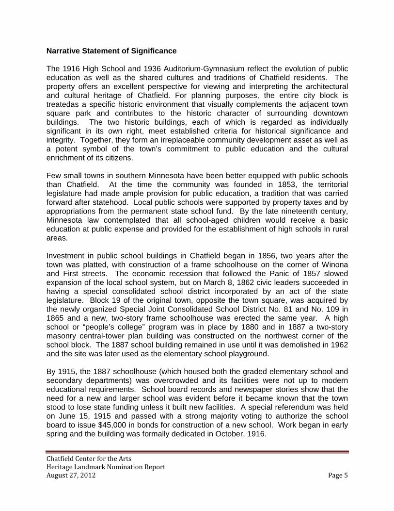
Narrative Statement of Significance The 1916 High School and 1936 Auditorium-Gymnasium reflect the evolution of public education as well as the shared cultures and traditions of Chatfield residents. The property offers an excellent perspective for viewing and interpreting the architectural and cultural heritage of Chatfield. For planning purposes, the entire city block is treatedas a specific historic environment that visually complements the adjacent town square park and contributes to the historic character of surrounding downtown buildings. The two historic buildings, each of which is regarded as individually significant in its own right, meet established criteria for historical significance and integrity. Together, they form an irreplaceable community development asset as well as a potent symbol of the town’s commitment to public education and the cultural enrichment of its citizens. Few small towns in southern Minnesota have been better equipped with public schools than Chatfield. At the time the community was founded in 1853, the territorial legislature had made ample provision for public education, a tradition that was carried forward after statehood. Local public schools were supported by property taxes and by appropriations from the permanent state school fund. By the late nineteenth century, Minnesota law contemplated that all school-aged children would receive a basic education at public expense and provided for the establishment of high schools in rural areas. Investment in public school buildings in Chatfield began in 1856, two years after the town was platted, with construction of a frame schoolhouse on the corner of Winona and First streets. The economic recession that followed the Panic of 1857 slowed expansion of the local school system, but on March 8, 1862 civic leaders succeeded in having a special consolidated school district incorporated by an act of the state legislature. Block 19 of the original town, opposite the town square, was acquired by the newly organized Special Joint Consolidated School District No. 81 and No. 109 in 1865 and a new, two-story frame schoolhouse was erected the same year. A high school or “people’s college” program was in place by 1880 and in 1887 a two-story masonry central-tower plan building was constructed on the northwest corner of the school block. The 1887 school building remained in use until it was demolished in 1962 and the site was later used as the elementary school playground. By 1915, the 1887 schoolhouse (which housed both the graded elementary school and secondary departments) was overcrowded and its facilities were not up to modern educational requirements. School board records and newspaper stories show that the need for a new and larger school was evident before it became known that the town stood to lose state funding unless it built new facilities. A special referendum was held on June 15, 1915 and passed with a strong majority voting to authorize the school board to issue $45,000 in bonds for construction of a new school. Work began in early spring and the building was formally dedicated in October, 1916.
Chatfield Center for the Arts Heritage Landmark Nomination Report August 27, 2012 Page 5

The Chatfield High School was designed by the Minneapolis architectural firm of Tyrie and Chapman. Architects William W. Tyrie (ca. 1875-1943) and George A. Chapman (1876-1950) designed numerous commercial, civic, and school buildings throughout the Midwest, including the St. James Hotel in Red Wing and the public school in New Ulm. Two other Minneapolis firms, Madsen Brothers and the Charles L. Pillsbury Company, were brought in as the general contract and engineers, respectively. Although members of the board of education met with the architects from time to time, the degree to which local officials were involved in the design process is difficult to determine. (No original plans or construction documents survive.) The decision to use a standardized plan seems to have been made quite early on, eliminating any need for architectural innovation. The plan, characterized by its imposing scale, informal architecture, and rigid organization of interior space, was typical of the standard plan schoolhouses built during this period in Minnesota and around the country. The school featured fireproof masonry walls and floors, specialized classroom spaces, multiple large classroom windows to allow for abundant natural lighting and ventilation, a modern steam heating system, and indoor plumbing with separate toilet rooms for girls, boys, and teachers. The school opened in the fall of 1916 to much fanfare and was widely regarded as a model of modern public school architecture. Built to enhance the educational experiences of Chatfield’s rapidly growing student population, it functioned as a high school until 1959 and was subsequently utilized as the district’s elementary school until June, 2009. Built as an addition to the high school, the auditorium-gymnasium was constructed in 1935-36 as a Public Works Administration (PWA) project. School board records and contemporary newspaper accounts show that the building was planned on a very fast track and that superintendent George H. Potter (1895-1954), then beginning his sixth year as head of the Chatfield public schools, was the prime mover behind the project. Potter had concluded that the existing facilities (1887 and 1916 buildings) were wholly inadequate for school assemblies, musical performances, and community gatherings and was able to persuade the board of education to support his concept of a “community center” large enough to accommodate district and regional events. It was also anticipated that the new building would allow the district to convert the existing high school gymnasium into two large classrooms to alleviate overcrowding—by 1935, high school enrollment had increased to 235, nearly double the designed capacity of the 1916 building. The genesis of the auditorium-gymnasium project is not recorded in great detail in the school board minutes, nor is it known precisely how or when the district initiated the request for federal government assistance. The PWA was a New Deal program that was created in 1933 to provide emergency relief to the construction industry during the depths of the Great Depression. On April 8, 1935, Congress appropriated $4.8 billion for public works and directed the Secretary of the Interior to make part of the funds available to the states for local projects. The Chatfield News reported on May 30 that the school board had discussed building a new auditorium and gymnasium with federal assistance and had reviewed preliminary plans prepared by Toltz, King & Day, Inc., a
Chatfield Center for the Arts Heritage Landmark Nomination Report August 27, 2012 Page 6
well known Saint Paul architectural and engineering firm. Three months later, the board called a special election to approve the $44,000 in general obligation bonds needed to finance the district’s share of the estimated $80,000 cost of construction. After a short but lively campaign the referendum was held on August 27 and when the votes were counted, the bond issue was approved 294 to 240. The state office of the PWA quickly rated the Chatfield project “A-1” and the school board directed Toltz, King & Day to prepare final plans and specifications. Within weeks, however, the project appeared to be dead in the water. Harry Hopkins (1890-1946), one of Franklin D. Roosevelt’s closest advisors and the administration’s relief administrator, had never been a strong supporter of the PWA and its focus on stimulating the construction industry; perhaps more importantly, Hopkins didn’t get along well with Secretary of the Interior Harold Ickes (1874-1952), whose department was responsible for coordinating PWA projects. After President Roosevelt established the Works Progress Administration (WPA) by executive order on May 6, 1935 and placed Hopkins in charge, he tried to steer more of the emergency relief appropriations to the WPA, which in contrast to the PWA emphasized projects that provided wages for the able-bodied unemployed. Hopkins cancelled the Chatfield project in early September, along with many other planned PWA undertakings involving nonfederal buildings, notwithstanding that they had already been approved by the PWA advisory council in Washington. Minnesota’s Congressional delegation, led by the state’s senior senator HenrikShipstead and Representative Elmer J. Ryan of South Saint Paul, lobbied successfully to have Secretary Ickes countermand the Hopkins decision and after some more interagency wrangling the projects were authorized to proceed. The official approval from the PWA arrived on October 1 and the next day Toltz, King and Day representatives met with school officials in Chatfield to let the auditorium project out for bids. Contracts were awarded in early November and site work began two days after the final plans were approved by the state PWA office on November 16. Construction work proceeded slowly at first because of poor weather and the project fell behind schedule; the work was not finished until late June, 1936, two months past the original date for completion. The delay caused the school district to delay graduation exercises for more than six weeks past the end of the school year. The new building was opened for public inspection on Sunday, July 26. The fifty graduating seniors of the Class of 1936 received their diplomas the following evening in front of the largest crowd ever assembled indoors in Chatfield up to that time. The auditorium-gymnasium in Chatfield was one of over thirty PWA public school building construction projects in Minnesota between 1934 and 1941. Spacious and well equipped, the facility was used for a wide array of school district and community events, ranging from school plays and assemblies to amateur sporting events. The gymnasium was the home court for boys and girls basketball and indoor baseball, and with over nine hundred seats the auditorium was perfectly suited for hosting large district and regional events. The sound-proofed band room was used year-round for music instruction and practice by students and the community band. The facility was officially
Chatfield Center for the Arts Heritage Landmark Nomination Report August 27, 2012 Page 7
renamed the George H. Potter Auditorium in 1972 and served as the school district’s primary performing arts venue until 2009. Ownership of both historic buildings was transferred to the city’s economic development agency early in 2010. Planning for what became the Chatfield Center for the Arts began in 2007. 7. BIBLIOGRAPHY Chatfield News. 1935-1936. Chatfield News-Democrat. 1915-1916. Kane and Johnson Architects, Inc.Report of On-Site Investigations of As-Built
Conditions Former Chatfield Elementary School. Report prepared for the Chatfield Economic Development Authority, February 16, 2010.
Toltz, King & Day, Inc. “Auditorium-Gymnasium Addition High School Building,
Chatfield, Minn.”Construction drawings.1935. Unpublished documents on file, City of Chatfield Public Works.
Vogel, Robert C. Intensive Survey and Evaluation of National Register of Historic
Places Eligibility of the School Block Properties (Chatfield High School Building & Auditorium-Gymnasium Addition), 405 South Main Street, Chatfield, Minnesota.Unpublished report, July 12, 2009.
8. PLANNING DATA
Zoning The Chatfield Center for the Arts is zoned R-1, Low Density Residential. Property Identification Number: 260231000
9. PLAN OF TREATMENT The City of Chatfield, through its Economic Development Authority, plans to renovate the historic property for adaptive use as a performing arts center. For residents of Chatfield and southeastern Minnesota, the acquisition, rehabilitation, and redevelopment of the former public school buildings will allow this property to continue to be a focal point of the community and region by providing a sense of place that is deeply rooted in national, state, and local history. Because each of the historic buildings represents a unique and irreplaceable cultural resource, preservation planning is critical to making the Chatfield Center for the Arts a success. The plan of treatment for the performing arts center focuses on preserving historically significant, character defining architectural features. These features represent a
Chatfield Center for the Arts Heritage Landmark Nomination Report August 27, 2012 Page 8

combination of design elements and materials that were created during the property’s period of historical significance (1916 to 1959) and therefore constitute the physical links between the past and the present. Because not everything that is old is necessarily worth preserving, preservation treatment strategies emphasize the conservation of specific architectural elements which are essential for conveying the property’s significant historical qualities and architectural values. The Secretary of the Interior’s Standards for the Treatment of Historic Properties will guide decisions made as part of the project design and construction process. Detailed guidelines for decisions involving the preservation, protection, and use of the property’s most important physical elements are to be found in the official Chatfield Center for the Arts Preservation Plan, first adopted in March, 2010 and periodically revised under the auspices of the Chatfield Heritage Preservation Commission. 10. ADDITIONAL DOCUMENTATION
The following items are attached to this report:
1) Location map 2) Site plan 3) First floor plan 4) Second floor plan 5) Basement floor plan 6) Photographs showing current conditions (4) 7) Historic photographs (2) 8) SHPO comment letter 9) Ordinance designating Chatfield Heritage Landmark 10) Preservation Plan
Chatfield Center for the Arts Heritage Landmark Nomination Report August 27, 2012 Page 9


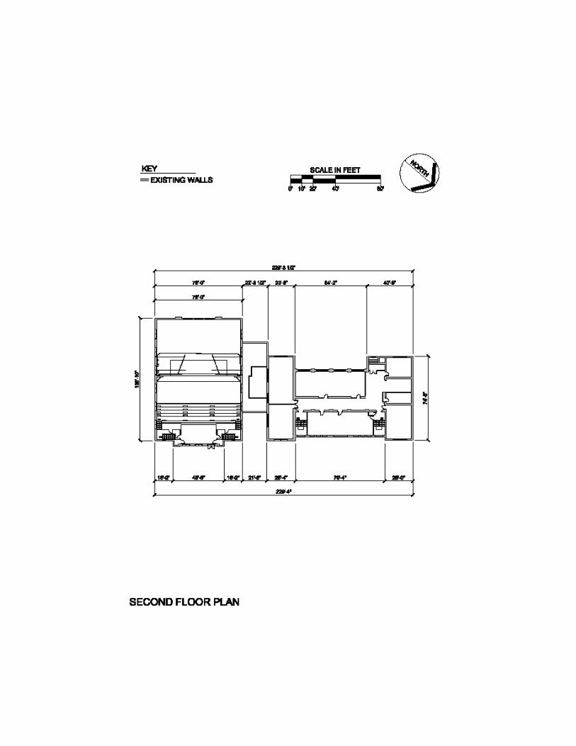
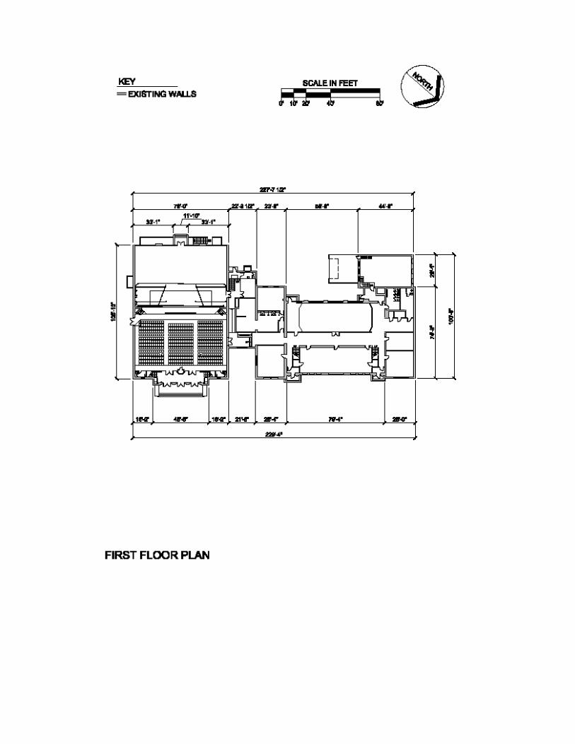
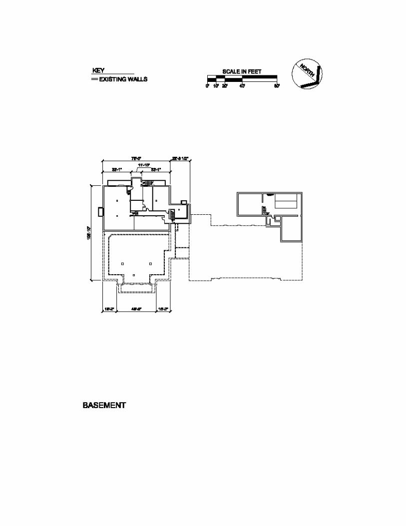
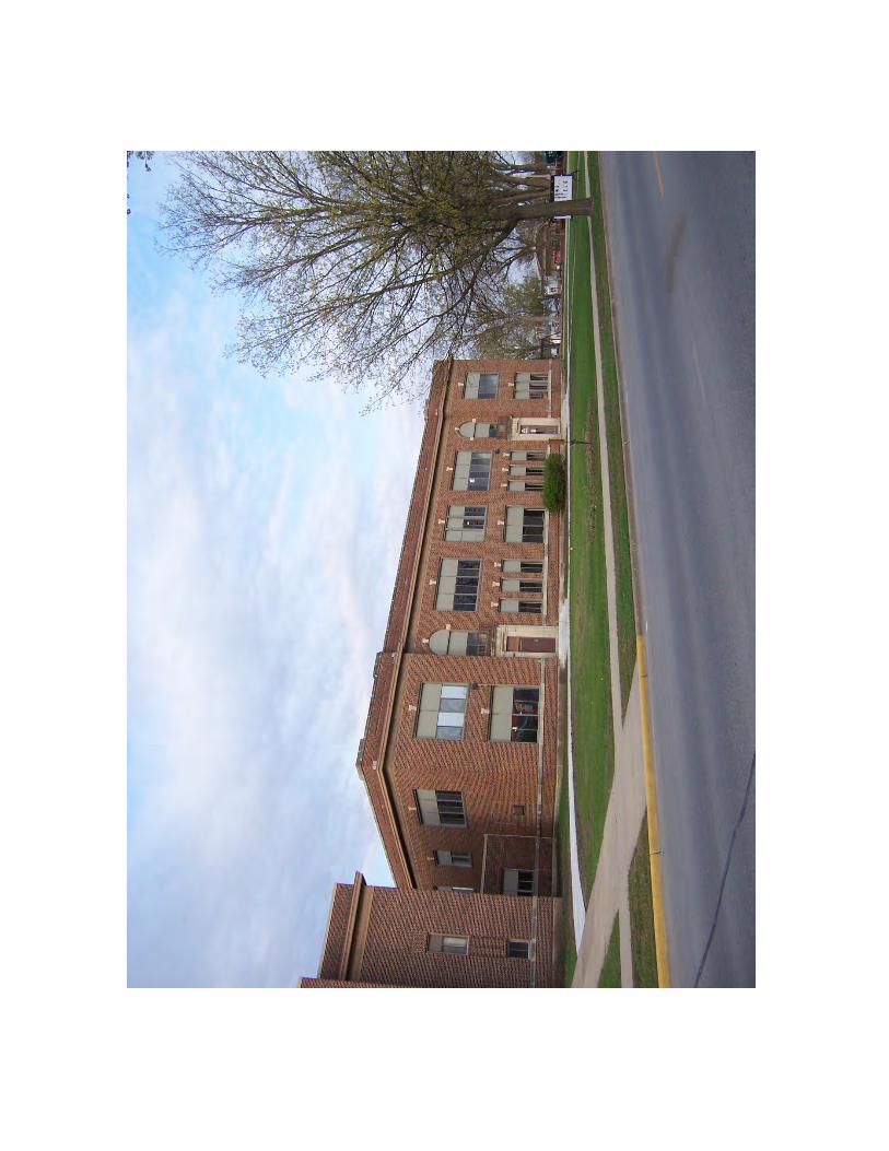

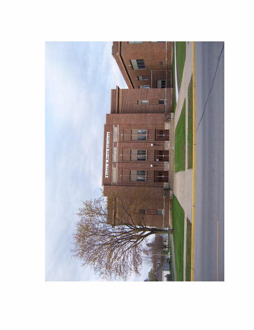


Ordinance designating Chatfield Heritage Landmark

Revised February 2012
CHATFIELD CENTER FOR THE ARTS
PRESERVATION PLAN Prepared by Robert C. Vogel
With contributions from Christian J. Hendrie, Linda C. Michie, Steven C. Harmon, and Patrick Waddick
Preservation Plan Chatfield Center for the Arts

City of Chatfield, Minnesota
TABLE OF CONTENTS
Introduction .................................................................................................................................................. 1
Project Concept ................................................................................................................................. 1 Description of Existing Conditions ...................................................................................................... 2 Historical Significance ........................................................................................................................ 3 Historic Character Defining Architectural Features .............................................................................. 3 General Standards for Preservation Projects ....................................................................................... 4 Critical Preservation Issues ............................................................................................................................. 6 New Lobby Addition........................................................................................................................... 6 Conservation of Historic Interiors ....................................................................................................... 7 Interim Security and Fire Safety Measures .......................................................................................... 8 Interpretation ……………………………………………. ...................................................................................... 8 Treatment Recommendations ........................................................................................................................ 9 1916 School Building .......................................................................................................................... 9 1936 Auditorium .............................................................................................................................. 12 Building Grounds ............................................................................................................................. 15
Preservation Plan Chatfield Center for the Arts

INTRODUCTION The City of Chatfield plans to renovate the historic Chatfield High School (hereafter referred to as the 1916 School Building) and the Auditorium-Gymnasium Addition (hereafter referred to as the 1936 Auditorium) for adaptive use as the Chatfield Center for the Arts. For residents of Chatfield, the acquisition, rehabilitation, and adaptive use of the former public school buildings will allow this property to continue to be the focal point of the community by providing a sense of place that is deeply rooted in community history. Because each of the historic buildings represents a unique and irreplaceable cultural resource, preservation planning is crucial to successful redevelopment of the property. This document builds upon a body of pre-development work which has been evolving since 2007, when a steering committee formed by the school district and the city established a strong, shared vision for the project and began gathering the necessary information to create a detailed development plan. An intensive survey and evaluation of the property’s historical and architectural significance was conducted by the city’s historic preservation planner, resulting in a determination of National Register eligibility by the Minnesota State Historic Preservation Office (SHPO) on August 5, 2009. With the SHPO opinion of National Register eligibility in hand, the stakeholders authorized development of the Preservation Plan, which evolved gradually over the course of several months. Simultaneously, more advanced feasibility studies and predesign work was undertaken in anticipation of the 2010 state bonding request. Creation of an architectural concept plan took time and creativity, and the steering committee approved predesign drawings prepared by the city’s team of preservation architects only hours before the transfer of ownership from the school district to the Chatfield Economic Authority (EDA) was executed on February 12, 2010. The Preservation Plan is project-specific and is intended to be utilized by the property owners to guide development and management decisions and to inform other planning documents. It is not a static document: as the project evolves from predevelopment into the construction phase, it will need to integrate new information that is developed as a result of additional research and design work. As such, it would be appropriate for it to exist only in an electronic format until it is redacted into actual construction documents. PROJECT CONCEPT The Chatfield Center for the Arts project as conceived will address three major initiatives with important historic preservation outcomes:
1. Renovation of the 1936 Auditorium, focusing on modernization of its electrical, stage lighting, acoustical, fire and life safety, and HVAC systems; restoration of the windows and doors; conversion of the former gymnasium area into specialized back of stage facilities; and installation of new restroom facilities on the lower level.
Preservation Plan Chatfield Center for the Arts Page 1
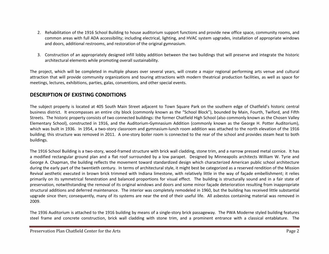
2. Rehabilitation of the 1916 School Building to house auditorium support functions and provide new office space, community rooms, and common areas with full ADA accessibility; including electrical, lighting, and HVAC system upgrades, installation of appropriate windows and doors, additional restrooms, and restoration of the original gymnasium.
3. Construction of an appropriately designed infill lobby addition between the two buildings that will preserve and integrate the historic
architectural elements while promoting overall sustainability. The project, which will be completed in multiple phases over several years, will create a major regional performing arts venue and cultural attraction that will provide community organizations and touring attractions with modern theatrical production facilities, as well as space for meetings, lectures, exhibitions, parties, galas, conventions, and other special events. DESCRIPTION OF EXISTING CONDITIONS The subject property is located at 405 South Main Street adjacent to Town Square Park on the southern edge of Chatfield’s historic central business district. It encompasses an entire city block (commonly known as the “School Block”), bounded by Main, Fourth, Twiford, and Fifth Streets. The historic property consists of two connected buildings: the former Chatfield High School (also commonly known as the Chosen Valley Elementary School), constructed in 1916, and the Auditorium-Gymnasium Addition (commonly known as the George H. Potter Auditorium), which was built in 1936. In 1954, a two-story classroom and gymnasium-lunch room addition was attached to the north elevation of the 1916 building; this structure was removed in 2011. A one-story boiler room is connected to the rear of the school and provides steam heat to both buildings. The 1916 School Building is a two-story, wood-framed structure with brick wall cladding, stone trim, and a narrow pressed metal cornice. It has a modified rectangular ground plan and a flat roof surrounded by a low parapet. Designed by Minneapolis architects William W. Tyrie and George A. Chapman, the building reflects the movement toward standardized design which characterized American public school architecture during the early part of the twentieth century. In terms of architectural style, it might best be categorized as a reserved rendition of the Mission Revival aesthetic executed in brown brick trimmed with Indiana limestone, with relatively little in the way of façade embellishment; it relies primarily on its symmetrical fenestration and balanced proportions for visual effect. The building is structurally sound and in a fair state of preservation, notwithstanding the removal of its original windows and doors and some minor façade deterioration resulting from inappropriate structural additions and deferred maintenance. The interior was completely remodeled in 1960, but the building has received little substantial upgrade since then; consequently, many of its systems are near the end of their useful life. All asbestos containing material was removed in 2009. The 1936 Auditorium is attached to the 1916 building by means of a single-story brick passageway. The PWA Moderne styled building features steel frame and concrete construction, brick wall cladding with stone trim, and a prominent entrance with a classical entablature. The
Preservation Plan Chatfield Center for the Arts Page 2
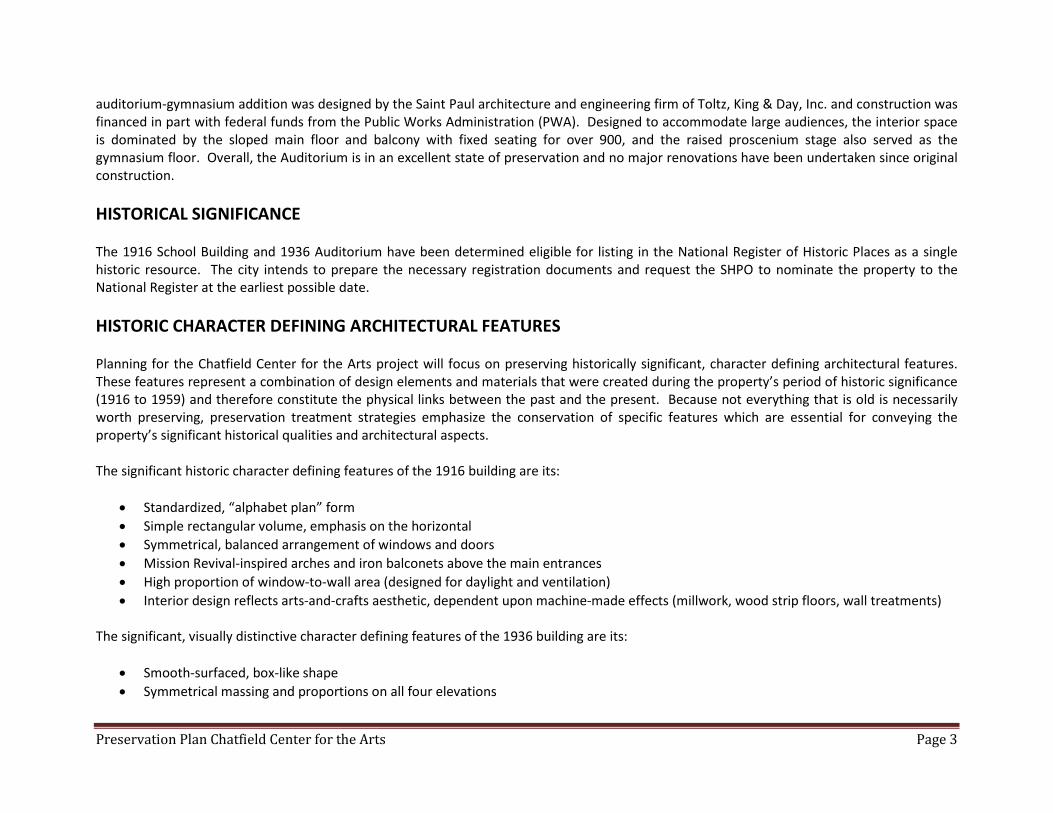
auditorium-gymnasium addition was designed by the Saint Paul architecture and engineering firm of Toltz, King & Day, Inc. and construction was financed in part with federal funds from the Public Works Administration (PWA). Designed to accommodate large audiences, the interior space is dominated by the sloped main floor and balcony with fixed seating for over 900, and the raised proscenium stage also served as the gymnasium floor. Overall, the Auditorium is in an excellent state of preservation and no major renovations have been undertaken since original construction. HISTORICAL SIGNIFICANCE The 1916 School Building and 1936 Auditorium have been determined eligible for listing in the National Register of Historic Places as a single historic resource. The city intends to prepare the necessary registration documents and request the SHPO to nominate the property to the National Register at the earliest possible date. HISTORIC CHARACTER DEFINING ARCHITECTURAL FEATURES Planning for the Chatfield Center for the Arts project will focus on preserving historically significant, character defining architectural features. These features represent a combination of design elements and materials that were created during the property’s period of historic significance (1916 to 1959) and therefore constitute the physical links between the past and the present. Because not everything that is old is necessarily worth preserving, preservation treatment strategies emphasize the conservation of specific features which are essential for conveying the property’s significant historical qualities and architectural aspects. The significant historic character defining features of the 1916 building are its:
• Standardized, “alphabet plan” form • Simple rectangular volume, emphasis on the horizontal • Symmetrical, balanced arrangement of windows and doors • Mission Revival-inspired arches and iron balconets above the main entrances • High proportion of window-to-wall area (designed for daylight and ventilation) • Interior design reflects arts-and-crafts aesthetic, dependent upon machine-made effects (millwork, wood strip floors, wall treatments)
The significant, visually distinctive character defining features of the 1936 building are its:
• Smooth-surfaced, box-like shape • Symmetrical massing and proportions on all four elevations
Preservation Plan Chatfield Center for the Arts Page 3
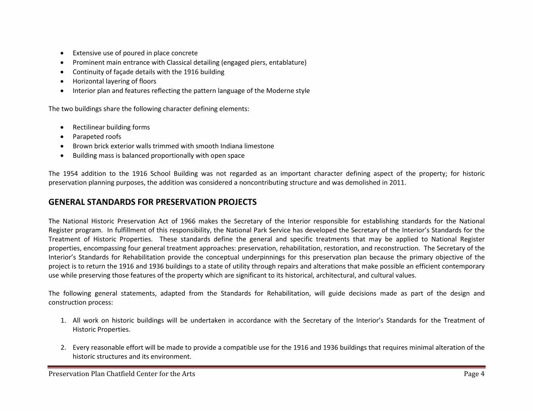
• Extensive use of poured in place concrete • Prominent main entrance with Classical detailing (engaged piers, entablature) • Continuity of façade details with the 1916 building • Horizontal layering of floors • Interior plan and features reflecting the pattern language of the Moderne style
The two buildings share the following character defining elements:
• Rectilinear building forms • Parapeted roofs • Brown brick exterior walls trimmed with smooth Indiana limestone • Building mass is balanced proportionally with open space
The 1954 addition to the 1916 School Building was not regarded as an important character defining aspect of the property; for historic preservation planning purposes, the addition was considered a noncontributing structure and was demolished in 2011. GENERAL STANDARDS FOR PRESERVATION PROJECTS The National Historic Preservation Act of 1966 makes the Secretary of the Interior responsible for establishing standards for the National Register program. In fulfillment of this responsibility, the National Park Service has developed the Secretary of the Interior’s Standards for the Treatment of Historic Properties. These standards define the general and specific treatments that may be applied to National Register properties, encompassing four general treatment approaches: preservation, rehabilitation, restoration, and reconstruction. The Secretary of the Interior’s Standards for Rehabilitation provide the conceptual underpinnings for this preservation plan because the primary objective of the project is to return the 1916 and 1936 buildings to a state of utility through repairs and alterations that make possible an efficient contemporary use while preserving those features of the property which are significant to its historical, architectural, and cultural values. The following general statements, adapted from the Standards for Rehabilitation, will guide decisions made as part of the design and construction process:
1. All work on historic buildings will be undertaken in accordance with the Secretary of the Interior’s Standards for the Treatment of Historic Properties.
2. Every reasonable effort will be made to provide a compatible use for the 1916 and 1936 buildings that requires minimal alteration of the historic structures and its environment.
Preservation Plan Chatfield Center for the Arts Page 4
3. All work will be designed and executed in a manner that preserves and sustains the distinguishing original qualities and historic
character-defining architectural features of the School Building and the Auditorium; no significant historic material or distinctive architectural feature will be removed or altered.
4. The historic property will be recognized as a product of its own time; for planning purposes, its period of historical significance is 1916 to 1959.
5. Changes which have taken place in the course of time will be treated as evidence of the property’s history and development. Although designed and built as an addition to the 1916 School Building, the 1936 Auditorium has acquired significance in its own right and its historical, architectural, and cultural values will be recognized and respected.
6. Distinctive stylistic features and examples of skilled craftsmanship will be treated with sensitivity.
7. Deteriorated architectural features will be repaired rather than replaced, wherever possible. Where replacement is necessary, the new material should match the material being replaced in composition, color, texture, and other visual qualities. Repair or replacement of missing architecture features should be based on accurate duplications of features, substantiated by historical, physical, or pictorial evidence, rather than on conjectural designs or the availability of different architectural elements.
8. The surface cleaning of the 1916 and 1936 buildings will be undertaken with the gentlest means possible. Under no circumstances will sandblasting or other harsh cleaning methods be undertaken that might damage historic building materials.
9. Every reasonable effort will be made to protect and preserve historic landscape resources in Town Square Park which may be affected by rehabilitation work on the 1916 and 1936 buildings.
Although they are neither regulatory nor prescriptive, the Secretary of the Interior’s Standards are the required basis for SHPO review and compliance with Section 106 of the National Historic Preservation Act, which would apply if any part of the Chatfield Center for the Performing Arts project were to become a “federal undertaking” due to the use of federal funds.
Preservation Plan Chatfield Center for the Arts Page 5

CRITICAL PRESERVATION ISSUES
Planning for the arts center project is focused on three critical historic preservation issues: design of the new lobby addition in the space between the 1916 and 1936 buildings, conservation of historic interiors in both buildings, and interim security and fire safety measures. The following pages provide information that supports the predesign concept approved by the project stakeholders in February, 2010. NEW LOBBY ADDITION The need to increase the amount of usable interior space and improve accessibility for persons with disabilities without significantly altering the appearance of either historic building presented a difficult design challenge. Traditionally, the preferred approach has been to design structural additions for historic buildings with the new work placed on a secondary (side or rear) elevation, but for this project the city’s historic architectural consultant team has developed a creative, yet practical alternative. The predesign plans call for construction of a two-story, glass-enclosed infill lobby addition in the space between the 1916 and 1936 buildings that will provide additional public areas, informal gathering space, and new elevator and stairway connections. Portions of the existing architecture are also incorporated in the new work, which reanimates the connection between the two historic buildings without obscuring or damaging significant historic character defining architectural details. The new work has been designed to meet current building code and accessibility requirements. The Secretary of the Interior has established the following specific standards for the design of structural additions in rehabilitation projects:
• Contemporary designs for alterations and additions to existing historic properties shall not be discouraged when such alterations and additions do not destroy significant historic, architectural, or cultural material and such design is compatible with the size, scale, color, material, and character of the property, neighborhood, or environment; and
• Whenever possible, new additions or alterations to structures shall be done in such a manner that if such additions or alterations were to be removed in the future, the essential form and integrity of the historic structure would be unimpaired.
The proposed new lobby addition has a major role to play in the sustainability of the redevelopment project. First and foremost, it will increase the amount of usable interior space without damaging significant historic architectural features and materials. The addition will make both historic buildings more functional by providing new public entrances and a reception area, with informal gathering space on both stories that can be used for displays of public art, information kiosks, and special exhibits. An interior elevator and stairways will provide new ADA compliant connections between the two historic buildings. (As designed, the elevator will provide access to the second floor of the 1916 building as well as
Preservation Plan Chatfield Center for the Arts Page 6

the lower level of the auditorium. Access to the balcony level in the auditorium would require construction of a concrete slab walkway inside the auditorium.) The design of the lobby addition is characterized by its transparent curtain walls of large glass panels set in steel frames, creating an open, light-filled space that envelops the historic passageway between the two buildings. The new construction will not radically change the profiles and proportions of the historic buildings and the lobby floors align with existing floor levels to help translate the rhythm of the historic spaces on either side. Most importantly, there will be minimal loss of historic fabric. Inside the lobby, the old brick walls and windows will be exposed, further enhancing the visual distinction between old and new construction. In economic terms, the planned infill lobby addition is more cost effective than an addition attached to the rear of the 1916 building because it avoids radical changes in the size, scale, and mass of the property and minimizes the amount of required new construction. The reduction in building footprint will translate into reduced construction costs. Because the new lobby will share existing systems with the historic buildings, the proportion of usable area will be increased. The dramatic design and enhanced aesthetic appeal should also result in a higher market appeal for the performing arts center. CONSERVATION OF HISTORIC INTERIORS The historical significance and integrity of the subject property rests in large measure upon its intact exterior features and overall architectural character. However, there are interior spaces, materials, and details in both buildings which are considered worthy of conservation because they help define the historic character of the property. While the existing interior features of the 1936 Auditorium will probably not require any substantial alteration, rehabilitation of the 1916 School Building will need to address reinforcement of inadequate structural system components, repairs to windows and doors, installation of new flooring in the former classrooms, electrical, plumbing and HVAC system upgrades, and other improvements that will probably have some effect on historic features, including stairs, handrails, baseboard and cornice moldings, skylights, lath and plaster walls and ceilings, windows, doorways, and floors. (The original classroom configuration and much of the pre-1959 interior architectural detailing was previously altered as a result of a succession of school remodeling projects, culminating in the 2009 asbestos abatement program.) All new interior work should be designed and carried out in a manner that preserves in place as much historic material as possible. Reinforcement required for structural stability or the installation of code-required structural and mechanical systems will need to be concealed, whenever possible, so as not to intrude or detract from the 1916 building’s aesthetic and historical qualities, except where concealment might result in the alteration or destruction of historically important materials or spaces.
Preservation Plan Chatfield Center for the Arts Page 7
INTERIM SECURITY AND FIRE SAFETY MEASURES Protecting the historic buildings against natural and man-made hazards is always a high priority, but security and fire safety are especially important when they are temporarily vacant, underused, or while renovation activities are underway. The most important hazards include vandalism, theft, arson, damaging wind and rainstorms, and animal action. Fire safety must be the number one priority: once a fire starts, a historic building is going to be irreversibly damaged, if not totally lost, regardless of the response time or skill of the fire fighters. Both buildings need to be protected, but the 1916 building is particularly vulnerable to fire, and the risk will increase whenever rehabilitation work is going on. The key to successful fire prevention is regular inspection and remedying hazards immediately. A fire fighting plan should also be developed and appropriate training exercises held on-site. The importance of integrating building security into historic preservation planning cannot be overstated. Statistically, historic properties are most likely to be broken into and vandalized whenever they are vacant and during renovation. Together with good door locks, basic outdoor and indoor security lighting systems will help reduce the risk of vandalism, theft, and arson by creating enough light to make the buildings visible from the street. Additional security lighting and police patrol may be required while high-risk activities are underway. New architectural lighting will need to be appropriate for use on a historic building and the fixtures should compliment, and not detract from, the property’s historic character defining features. INTERPRETATION Interpretation will help visitors and users to gain a better understanding of the 1916 and 1936 buildings and help everyone become wholly integrated with the past, the present, and the future of the Chatfield Center for the Arts. When done effectively, it can bridge the gap of time, provide personal relevance, and broaden perspectives—and because we protect what we understand and value, interpretation is an important aspect of preservation planning because it fosters heritage stewardship at a personal and community level. Among other benefits, historical interpretation can provide a sense of regional and community pride which will enhance the property’s value as a cultural tourism attraction. Planning for historic interpretation will need to establish goals that compliment preservation and rehabilitation treatment strategies. The arts center buildings are well suited for interpretation because they represent historically important and architecturally noteworthy building types and the buildings themselves reflect diverse historical and cultural themes. Available historical documentation, including archival photographs, architectural plans, and written information, will serve as the basis for developing meaningful, provocative, and interesting interpretive programs. Traditional interpretation activities would include guided tours, self-guided brochures, computer-aided tours, exhibits, and signs directed at arts center patrons. More ambitious interpretive programs could involve “virual” tours on the Internet or interactive multimedia kiosks with touch-screen displays. Interpretation could also include outdoor exhibits and historical markers designed to assist casual visitors who are passing through the area.
Preservation Plan Chatfield Center for the Arts Page 8

TREATMENT RECOMMENDATIONS This section provides detailed guidance for decisions involving the preservation, protection, and use of the historic property by delineating those important architectural elements which require special protection and recommending specific treatments that are economical but do not sacrifice historic integrity. The recommendations will inform the preparation of detailed construction drawings and other planning documents. 1916 SCHOOL BUILDING Adaptive use is the only way that the 1916 School Building will be preserved and to be successful, rehabilitation treatments will need to respect and retain the building’s historical significance and architectural integrity, while adding a contemporary layer that provides value for the future. The primary objective is to return the building to a state of utility through repairs and minor alterations that will make possible an efficient new use while preserving those features which are significant to its historical and architectural values. Structural Systems
• Rehabilitation treatments need to recognize the special problems inherent in the building’s structural systems.
• Adequately treat all known structural problems at the earliest opportunity. Damaged, weakened, or inadequate structural systems should be stabilized and repaired, and replaced only when necessary.
• Minimize the use of heavy machinery that could disturb foundation walls or undermine the structural stability of the building. Walls
• The original brick wall cladding and stone trim should be retained.
• Existing brickwork should be repointed only where there is visible evidence of moisture problems or where mortar is missing; and the old mortar should be duplicated in composition, color, joint profile, and texture.
• Deteriorated or damaged masonry should be repaired; if replacement is necessary, the new brick, stone, or concrete should duplicate the old as closely as possible.
Preservation Plan Chatfield Center for the Arts Page 9

• The original metal cornice should be retained. Where necessary, deteriorated or missing material should be repaired or replace in-kind. Roof
• If may be necessary to modify the shape and material of the existing light-frame truss roof. The new roof should not be visible from the street.
• The parapet walls contribute to the building’s architectural character and should be preserved intact.
• The original skylights should be restored. Installation of new skylights is appropriate, provided they are not visible from the street. Windows and Doors
• The location and size of existing window and door openings need be retained.
• The existing window sash is inappropriate and should be replaced with custom wood double-hung sash that replicate the original windows in design, material, and hardware.
• New storm windows and screens should be visually unobtrusive.
• The wrought-iron balconets and arched window surrounds above the entrances (facing Main Street) are important to the property’s historic integrity and should be retained.
• New doors should duplicate the design, materials, and hardware of the originals. Entrances
• Ramps for handicap accessibility in relation to the entrances on the Main Street elevation should be designed so that they do not detract from their originally intended appearance.
• If a ramp for handicap accessibility is required on the Twiford Street elevation, the existing doorway, door, and steps may need to be altered to fully comply with ADA requirements.
Preservation Plan Chatfield Center for the Arts Page 10
Exterior Finishes
• Clean masonry walls only when necessary to halt deterioration or to remove stains. Always use the gentlest means possible, such as low pressure water and scrubbing and rising using soft natural bristle brushes. The use of chemical cleaning products is generally not recommended.
• Historic masonry exposed by demolition of the 1954 classroom wing should be cleaned using hand tools.
• Cleaning of the cornice should use appropriate architectural metals cleaning substances and methods that will not abrade the surface or alter the color of the original sheet metal.
Interior Features & Finishes
• Retain as much original material as possible.
• Remove dropped ceilings.
• Avoid installing new decorative treatments which use historically inappropriate materials, such as vinyl, plastic or imitation wood paneling or flooring (except in utility areas).
• Repair damaged or deteriorated lath and plaster walls and ceilings, wooden moldings, wood paneling, and terrazzo floors, replacing damaged or deteriorated material with new material that duplicates the old as closely as possible.
• Demolition of non-load bearing walls and partitions is an appropriate rehabilitation treatment.
• Restore the historic skylights; new skylights would be appropriate for public rooms.
• Replace the wood floors removed as part of the 2009 asbestos abatement program with new hardwood flooring (preferably from trees cut and milled in southeastern Minnesota).
• Whenever possible, use native species for new woodwork, including doorways, windows, baseboards, and moldings.
Preservation Plan Chatfield Center for the Arts Page 11
• Discover the original paint colors, finishes and other decorative finishes.
• Remove paint from wood trim that was painted over. When treating unpainted woodwork, complete stripping may not be necessary for removing damaged or deteriorated finishes.
Mechanical Systems
• HVAC and other mechanical systems should be installed in areas and spaces that will require the least possible loss of historic fabric.
• Adapt and reuse as much of the original heating and ventilating systems as possible. Safety and Code Requirements
• Comply with building and fire code requirements and install life safety measures in such a manner that the essential historic character of the building is not harmed.
• Provide for adequate safety without dependence on any single safeguard.
• Install automatic sprinkler systems that are visually unobtrusive. Garage
• The existing garage (currently used for storage) on the back of the building is not a historic structure; it distracts from the property’s historic character and therefore should not be retained.
1936 AUDITORIUM Adaptive use of the 1936 Auditorium should have minimal impact on the building’s architectural integrity. However, to ensure that its historic fabric will be properly cared for, while making better use of the building itself, renovation will need to apply measures that preserve intact the existing form, integrity, and materials of the building’s exterior. There will need to be minor alterations to some interior spaces in order to make the auditorium more efficient.
Preservation Plan Chatfield Center for the Arts Page 12
Walls
• The original brick, stone, and concrete masonry and mortar should be retained.
• Brickwork should be repointed only where there is visible evidence of moisture problems or where mortar is missing; and the old mortar should be duplicated in composition, color, joint profile, and texture.
• Deteriorated or damaged masonry should be repaired. If replacement is necessary, the new brick, stone, or concrete should duplicate the old as closely as possible.
• The original metal cornice should be retained. Wherever necessary, deteriorated or missing material should be repaired or replaced in-kind.
Roof
• The original roof shape should be preserved and the original roof material should be retained.
• The parapet walls contribute to the building’s architectural character and should be preserved intact. Windows and Doors
• The location and size of existing window and door openings will need to be retained.
• The existing windows are not appropriate and should be replaced with custom windows that duplicate the design and material of the originals.
• New storm windows and screens should be visually unobtrusive.
• New main entry doors should duplicate the design, material, and hardware of the originals. Entrances
• The classical detailing and concrete steps leading to the main entrance should be retained intact.
Preservation Plan Chatfield Center for the Arts Page 13

Exterior Finishes
• Clean masonry walls only when necessary to halt deterioration or to remove stains. Always use the gentlest means possible, such as low pressure water and scrubbing and rising using soft natural bristle brushes. The use of chemical cleaning products is generally not recommended.
• Cleaning of the cornice should use appropriate architectural metals cleaning substances and methods that will not abrade the surface or alter the color of the original sheet metal
Interior Features & Finishes
• Retain all of the historically significant, character-defining interior features of the auditorium including the main floor and balcony seating areas, the proscenium stage, lobby, and mezzanine-level board room.
• Preserve as much as possible of the 1936 floor plan, the spatial relationship and size of the rooms, corridors, and other aspects of the original design.
• Retain as much original material, architectural features, and hardware as possible and avoid installing new decorative material that is historically inappropriate, such as vinyl or imitation wood paneling (except in utility areas).
• Repair damaged or deteriorated walls, ceilings and floors, replacing damaged or deteriorated material with new material that duplicates the old as closely as possible.
• Restore the Board Room to recover the decorative details as it appeared at a specific point in time during the property’s period of historical significance (1936-1959).
• Discover the original paint colors and decorative finishes in public areas. Mechanical Systems
• New HVAC and other mechanical systems should be installed in areas and spaces that will require the least possible alteration of the auditorium’s physical appearance.
Preservation Plan Chatfield Center for the Arts Page 14
Safety and Code Requirements
• Comply with building and fire code requirements and install life safety measures in such a manner that the essential historic character of the building is not harmed.
• Provide for adequate safety without dependence on any single safeguard.
• Install automated sprinkler systems that are visually unobtrusive. BUILDING GROUNDS
Treatment of the building grounds will be guided by the concept of rehabilitation. The open space areas would be set aside for pedestrians and provide for multiple uses, including outdoor exhibits and special events. It is anticipated that the parts of the property adjoining Town Square Park will quickly evolve into a people-oriented outdoor destination in its own right.
Spatial Organization and Setbacks
• The School Block physically and historically comprises a specific environment with its own unique identity of time and space. New landscape architecture needs to respect the spatial relationships between component elements of the property and downtown streetscape.
• The existing building setbacks from public streets should be retained.
• Redevelopment should not include large areas of off-street parking anywhere inside the boundaries of the historic property (except for restricted parking along Fourth Street and temporary truck parking in the service areas behind the auditorium).
Topography and Landscaping
• Identify, retain, and preserve historic topographic features, including lawns and circulation features.
• Preserve existing grades and land surfaces except to correct drainage problems.
• Evaluate the condition and determine the age of the historic retaining wall along Fifth Street; stabilize, protect, and maintain the historic stone work and replace in-kind those portions which are too deteriorated to repair; the new stone work should match the original in composition, color, and texture.
Preservation Plan Chatfield Center for the Arts Page 15

Vegetation
• Identify and retain trees, shrubbery and other plantings that reflect the history and development of the property, particularly those which were in place during its period of historic significance.
• Install new plantings that are compatible with the historic character of the property.
• Monitor the age, health and vigor of boulevard trees.
• Recognize that day-to-day, seasonal, and cyclical grounds keeping and other horticultural tasks can cumulatively alter the character of the historic landscape.
Circulation
• Retain the walkways that have traditionally linked the historic buildings to their environment.
• Maintenance and repair of walkways should emphasize retention of the maximum amount of existing concrete surface while utilizing as little new material as possible; repairs to existing walkways should be non-destructive.
• Limited replacement in-kind of missing or extensively deteriorated portions of historic walkways and steps would be appropriate; the replacement material should match the historic surfaces both physically and visually.
• New walkways and steps should be physically and visually compatible with historic structures. Structures, Furnishings & Objects
• Install new street lights, benches, and signs that are visually compatible with the character and mood of the historic property.
Preservation Plan Chatfield Center for the Arts Page 16

Accessibility
• Because accessibility to historic buildings is required by the Americans with Disabilities Act, it may be necessary to modify some existing landscape features, such as walkways and vehicle parking areas, to bring them into compliance with accessibility code requirements; the goal is to provide the highest level of access with the lowest level of impact on the integrity of historic landscape features.
• Properly designed and installed ramps for handicap accessibility should not detract from the historic integrity of the buildings and their setting.
Town Square Park
• The historic town square park is a historically significant vernacular landscape feature that contributes to the historic character of the Center for the Arts; planning for future park improvements must strike a balance between change and continuity.
• Arrange for an intensive historic preservation study of the park to reconstruct in detail the history of its development and public use, document historically important landscape features, and evaluate its historic significance and integrity. If eligible, the park should be nominated to the National Register of Historic Places and designated as Chatfield Heritage Landmark.
• Preserve trees, walkways, structures, and objects that contribute to the historic significance of the park and are therefore worthy of preservation.
• The programmatic needs of the city park need to be balanced against historic preservation requirements.
Preservation Plan Chatfield Center for the Arts Page 17