CHASSIS ENGINEERING GUIDELINES NZ... · Recommended maximum design stress = 35%* of chassis yield...
6
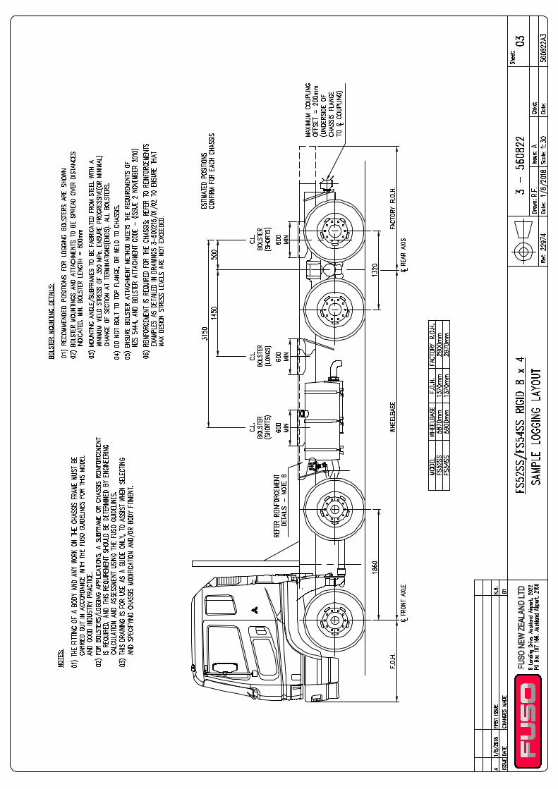
DESIGN GUIDELINES FOR: MODELS: FUSO HD 8x4 FS52SS, FS54SS (ISSUE A, AUGUST 2018) fuso.co.nz This specification sheet applies to vehicles supplied by Fuso NZ for the New Zealand market. REF: J22974 / S-HDEURO5SUA.DWG Copyright © Fuso NZ (2018) These recommendations have been prepared for design engineers and body builders as a guide to assist when selecting and specifying chassis modification and/or body fitment. These guidelines should be read in conjunction with the Mitsubishi Fuso Truck & Bus Body Equipment Mounting Directives available on the FUSO Body Builder Portal. Use these guidelines to determine any reinforcement details required for each application. Hot Rolled Steel, 540 MPa tensile, 380 MPa yield. Frame reinforcements should be balanced in terms of frame strength. Bolster mounts of an appropriate size and shape could contribute to the total frame strength. Recommended maximum design stress = 35%* of chassis yield stress (133 MPa) for sections of frame that are unmodified or do not contain stress raisers. Appropriate allowance should be made for details in the frame that have been modified or contain stress raisers. Refer to the body builders manual for stress levels using static load applications. For heavy duty, more arduous applications, eg., sidelifter, the stress levels should be reduced a further 33% to enhance frame durability. Recommended heavy duty design stress = 2/3. Recommended max design stress = 90 MPa. CHASSIS ENGINEERING GUIDELINES CHASSIS FRAME MATERIAL APPLICATIONS - FLAT DECK, CURTAINSIDER, TIPPER, LOGGER MAXIMUM DESIGN STRESS LOAD CONSIDERATIONS FLAT DECK U.D.L. Consider as a uniformly distributed load over whole or part of deck length. CURTAINSIDER Consider as a uniformly distributed load over whole or part of deck length in conjunction with point loads imposed by body and taillifts. LOAD CENTRE Determined as water level load 600mm above chassis. TIPPER AT LIFT OFF Point when body raised just clear of the chassis thus imposing two point loads on the chassis rails at hinge and hoist mount. AT MAX TIP Point when the body is raised to tip angle of 48°, (tail door closed) so loads act at the hoist mounting and hinge pivot points. LOAD CENTRE Determined as water level load 600mm above chassis. SPREADING Spreader work imposes higher frame loads and may require chassis reinforcement. LOGGER LONGS/SHORTS Consider as a point load applied through bolster mounting positions. Use Bolster attachment code. MAXIMUM CHASSIS DEFLECTION CASE 1 Between front and rear axis. Maximum permissible deflection: ±8mm. CASE 2 Rear overhang. Maximum permissible deflection: 15mm at 1000mm or greater, rear of rear axis.
Transcript of CHASSIS ENGINEERING GUIDELINES NZ... · Recommended maximum design stress = 35%* of chassis yield...
DESIGN GUIDELINES FOR: MODELS:
FUSO HD 8x4 FS52SS, FS54SS
(ISSUE A, AUGUST 2018)
fuso.co.nz
This specification sheet applies to vehicles supplied by Fuso NZ for the New Zealand market. REF: J22974 / S-HDEURO5SUA.DWGCopyright © Fuso NZ (2018)
These recommendations have been prepared for design engineers and body builders as a guide to assist when selecting and specifying chassis modification and/or body fitment. These guidelines should be read in conjunction with the Mitsubishi Fuso Truck & Bus Body Equipment Mounting Directives available on the FUSO Body Builder Portal. Use these guidelines to determine any reinforcement details required for each application.
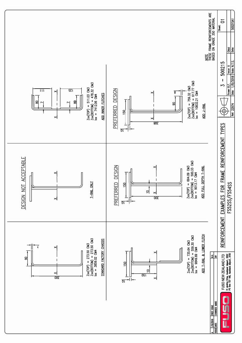
Hot Rolled Steel, 540 MPa tensile, 380 MPa yield.
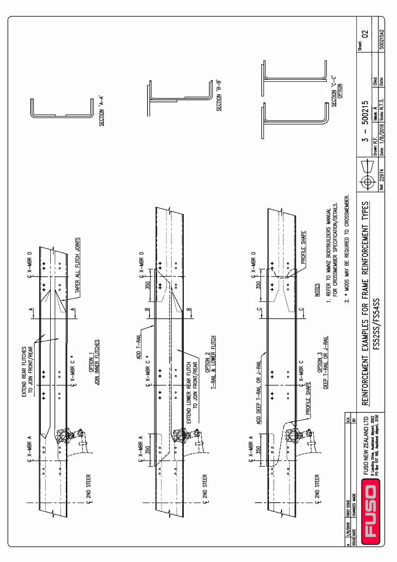
Frame reinforcements should be balanced in terms of frame strength. Bolster mounts of an appropriate size and shape could contribute to the total frame strength.
Recommended maximum design stress = 35%* of chassis yield stress (133 MPa) for sections of frame that are unmodified or do not contain stress raisers. Appropriate allowance should be made for details in the frame that have been modified or contain stress raisers. Refer to the body builders manual for stress levels using static load applications. For heavy duty, more arduous applications, eg., sidelifter, the stress levels should be reduced a further 33% to enhance frame durability.Recommended heavy duty design stress = 2/3. Recommended max design stress = 90 MPa.
CHASSIS ENGINEERING GUIDELINES
CHASSIS FRAME MATERIAL
APPLICATIONS - FLAT DECK, CURTAINSIDER, TIPPER, LOGGER
MAXIMUM DESIGN STRESS
LOAD CONSIDERATIONS
FLAT DECKU.D.L. Consider as a uniformly distributed load
over whole or part of deck length.CURTAINSIDER Consider as a uniformly distributed load
over whole or part of deck length in conjunction with point loads imposed by body and taillifts.
LOAD CENTRE Determined as water level load 600mm above chassis.
TIPPERAT LIFT OFF Point when body raised just clear of the
chassis thus imposing two point loads on the chassis rails at hinge and hoist mount.
AT MAX TIP Point when the body is raised to tip angle of 48°, (tail door closed) so loads act at the hoist mounting and hinge pivot points.
LOAD CENTRE Determined as water level load 600mm above chassis.
SPREADING Spreader work imposes higher frame loads and may require chassis reinforcement.
LOGGERLONGS/SHORTS Consider as a point load applied through
bolster mounting positions.Use Bolster attachment code.
MAXIMUM CHASSIS DEFLECTION
CASE 1 Between front and rear axis. Maximum permissible deflection: ±8mm.
CASE 2 Rear overhang.Maximum permissible deflection: 15mm at 1000mm or greater, rear of rear axis.
A 1/8
/2018
FIRST
ISSUE
ISSU
DATE
CHAN
GES MAD
E
� I
I� ...
r-
... ..,
...
g
X __
_ x
�1 I T X
Zxx(
TOP)
= 2
73.5
0 CM
3 Zx
x(BO
TTOM
) =
273.
50 C
M3
lxx =
385
9.02
CM4
STAN
DARD
FACTO
RY C
HASS
IS
150
X
Zxx(
TOP)
= 7
35.6
4 CM
3 Zx
x(BO
TTOM
) =
559.
30 C
M3
lxx =
984
9.69
CM4
ADD
T-RA
IL &
LOWE
R FU
TCH
K.H.
BY
DESIG
N NO
T AC
CEPT
ABLE
X _
_ x
T-RA
IL ON
LY
PREF
ERRE
D DE
SIGN
�11
150
T o___
x �-H
___x
g Zx
x(TO
P) =
694
.09 C
M3
Zxx(
BOTT
OM)
= 50
0.33
CM3
lxx =
901
3.17
CM4
ADD
FULL
DEP
TH T
-RAIL
�
X __
_ x
�
0
Zxx(
TOP)
= 5
11.03
CM3
Zx
x(BO
TTOM
) =
478.
32 C
M3
lxx =
741
2.06
CM4
ADD
INNE
R FU
TCHE
S
PREF
ERRE
D DE
SIGN
�1_1
150
t
00
___ x ---tt
+-__
_ x
90
_j_
Zxx(
TOP)
= 7
59.3
2 CM
3 Zx
x(BO
TTOM
) =
617.
77 C
M3
lxx =
108
32.2
1 CM
4
ADD
J-RA
IL NO
TE
THES
E FR
AME
REIN
FORC
EMEN
TS A
RE
BASE
D ON
GRA
DE 3
50 M
ATER
IAL
Sheet
: Fu
so N
EW ZE
ALAN
D LT
D RE
INFOR
CEME
NT E
XAMP
LES
FOR
FRAM
E RE
INFOR
CEME
NT T
YPES
01
�ola:
"fo��:s
.tC:�/
lT�.�flc
FS
52SS
/FS5
4 SS
Ret.
2297
4 Dat
e: 1
8 20
18 S
cale:
N.T.S
. Ch
kd:
Date:
50
0215
A1
X-MB
R A
___
____
----
--·
_ o_
o _
_ --
· o
o __
".)
--
--
--
--
--
--
· -
-_
Q -
0....-
£ 2N
D ST
EER
I I
I �5
\.L-
-11--�
�
-
£ X-M
BR A
35
0
EXTE
ND R
EAR
FUTC
HES
TO J
OIN
FRON
T /REA
R
++
0
0
++
0
0
£ X-M
BR C
*
OPTIO
N 1
JOIN
INNE
R FL
ITCHE
S
ADD
T-RA
IL £ X
-MBR
C *
£ X-M
BR D
TAPE
R AL
L FU
TCH
JOIN
TS
X-MB
R D
B 35
0
--��- , �
-�-���
�- :. �:�:
��t��
:_:-�-�
�-"_)-_-
_-_-_-_-
_--_:
-:--�-
-�--•-:
----
-_-_-_-
_-_-_-_-
_-______
_ 1 _ __
_
-_
_ -� --�- �-:
-�:--�+ t�-::---
-· -· ------
-· -· -----
£ 2N
D ST
EER
--
--
--
--
--
--
· -
-_
0 _
0 _
£ 2N
D ST
EER
A 1/8
/2018
FIRST
ISSUE
ISSUE
DAlE
CHAN
GES MAD
E
I I
I �5
\. L-
-11--�
�
-
X-MB
R A
350
EXTE
ND L
OWER
REA
R FU
TCH
TO J
OIN
FRON
T/REA
R
OPTIO
N 2
T-RA
IL &
LOWE
R FU
TCH
ADD
DEEP
T-R
AIL O
R J-
RAIL
K.H.
BY
++
+
+
0
0
0
0
£ X-M
BR C
PR
OFILIE
SHA
PE
OPTIO
N 3
DEEP
T-R
AIL O
R J-
RAIL
B
X-MB
R D
L _ __
++
j
,-+-+
____
_____
:: o
-o
-u�.
o -
o --
-· -
· --
----
-· -
· --
--1
\
C PR
OFILE
SHA
PE
NOTE
S
1. RE
FER
TO M
MNZ
BODY
BUILD
ERS
MANU
AL
FOR
CROS
SMEM
BER
SPEC
IFICAT
ION/
DETA
ILS.
2.*
MODS
MAY
BE
REQU
IRED
TO C
ROSS
MEMB
ER.
FU
SC
Fu
so N
EW ZE
ALAND
LTD
REINF
ORCE
MENT
EXA
MPLE
S FO
R FR
AME
REINF
ORCE
MENT
TYP
ES
� �'::"
M"1':e
. %C:::/
1Trp°';i, 2 ��
FS
52SS
/FS5
4SS
SECT
ION
'A-A'
SECT
ION
'8-8
'
SECT
ION
·c-c·
OPTIO
N
�
Sheet
:
� ._ D
-r aw-n:
-R3 -.F_-
-5 -� - s� - e� -} -5 -
-- Ch-k
d-: -
-�
--0 -2 -
----'
Ret.
2297
4 Dat
e: 1
8 20
18 Sc
a le: N
.T.S.
Date:
5002
15A2