Charlotte Mecklenburg Utilities
24
Daylighting + Energy Performance Laboratory – UNC Charlotte Charlotte Mecklenburg Utilities: Administration/Engineering Facilities Renovation Morris Berg Architects 6101 Carnegie Blvd.; Suite 101 Charlotte, NC 28209 Base Case Daylighting Analysis March 19, 2009
description
Daylighting and performance analysis.
Transcript of Charlotte Mecklenburg Utilities
Daylighting + Energy Performance Laboratory – UNC Charlotte
Charlotte Mecklenburg Utilities: Administration/Engineering Facilities Renovation
Morris Berg Architects 6101 Carnegie Blvd.; Suite 101
Charlotte, NC 28209
Base Case Daylighting Analysis
March 19, 2009
Table of Contents:
Introduction to analysis pg. 1-7: Summary and explanation of analysis
North/South Section Analysis Pg. 8-16 West Section Analysis Pg. 17-20 Southeast Section Analysis Pg. 21-23
Analysis: 1. Direct Solar Penetration and Shading Analysis
This is an assessment of different shading options. Its purpose is to suggest improvements such as optimizing the size and angle of the horizontal shading fins as well as the proper orientation of vertical shading devices. Digital modeling and rendering will be used to inform our decisions.
2. Daylighting Analysis, specifically the impact of shading
Digital modeling and rendering have been used to assess the impact and benefit of the shading devices implemented in previous design decisions. Floor plans and sections have been rendered with conscious regard to the reduction of direct solar heat gain while still providing adequate daylight to interior spaces
3. Refined Direct Solar Penetration and Shading Analysis
Any refinements to the shading that are critical have been simulated and verified by this study.
4. Solar Heat Gain Calculations
Additional solar heat gain calculations have been done based on new shading design and/or alternate glazing if needed.
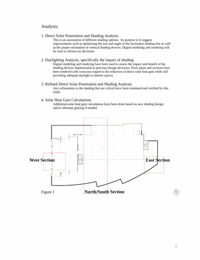
West Section East Section Figure 1 North/South Section
1
Summary of analysis: The base case building will allow too much direct solar penetration, which calls for shading on the south, east, and west facades. The analysis illustrates the positive impact of proper shading devices and light shelves. Different shading configurations were used on the different elevations in a response to the changing conditions due to the nature of the building’s solar orientation. Vertical shading elements were shown to be the most effective on both the east and west elevations, and horizontal elements were the most successful on the southern elevation. The southern horizontal shading wraps the building on the east façade and provides a visual connection from the front to the side of the building. It also provides a much-needed response to the southern sun that begins to directly affect the southeast corner of the building. This analysis of the shading elements on the facade has informed the options for elevation design as well as how to generally lay out building program in relation to the window wall. Direct solar penetration has been largely alleviated on all facades where shading devices were implemented. The areas that are still affected by direct solar penetration are minimal, and the worst penetration occurs outside of the standard working day, and thus less of an issue. The reduction in direct solar penetration at the view window also drastically reduces glare at the view window, and lessens the strain on the occupant’s eyes. Since glare has been reduced at the window wall, there is less of a contrast between the interior and exterior spaces near the window wall, which improves the conditions for the occupants within the spaces near the window wall. Overall, the orientation of the building in combination with the shading devices analyzed allow for maximum daylight distribution within the building, while largely reducing the amount of direct solar penetration and subsequent heat gain. The building’s performance will increase if the parametric analysis shown leads to the implementation of the shading devices and window treatments on all facades.
2
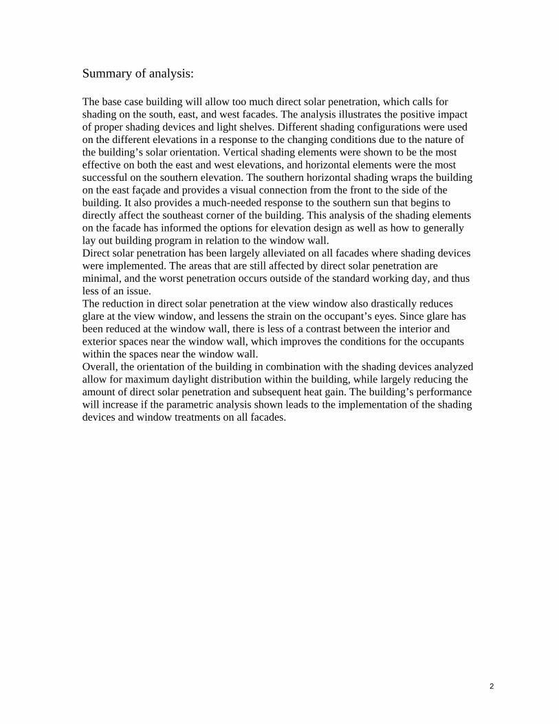
Daylighting depth of 20’-0”: 1st and 2nd Floors The potential for daylighting the building is directly a result of the elements of the envelope and the sectional volume of the adjacent spaces. The basic assessment of daylight potential assumes a 20’ depth perpendicular to the window wall. These figures illustrate the percentage of regularly occupied space that will benefit by daylight strategies. Approximately 37% of the building volume can be daylit through the vertical window wall. Additional daylighting area maybe increased through judicious application of skylights above the second floor. -Percentage of regularly occupied space that is daylit: 35% -Percentage of regularly occupied space that is daylit: 40%
3
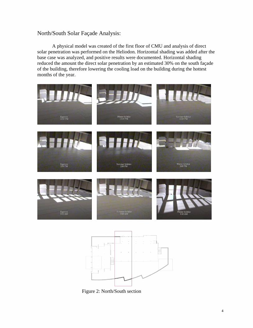
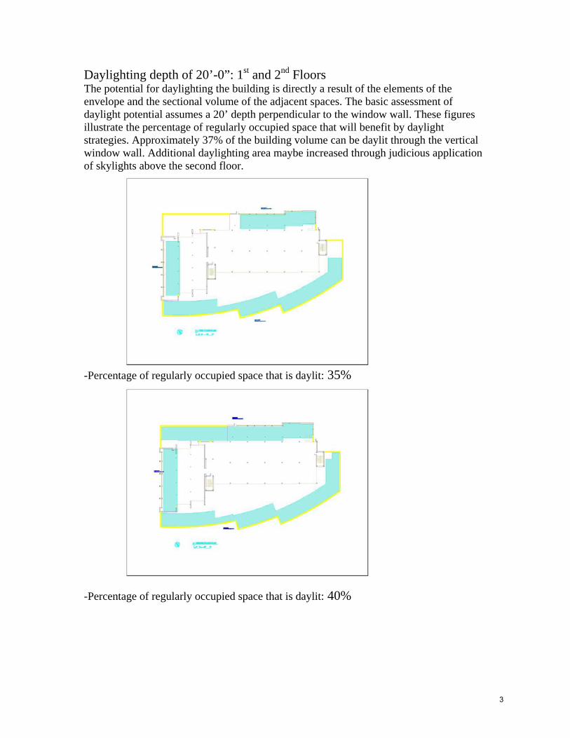
North/South Solar Façade Analysis:
A physical model was created of the first floor of CMU and analysis of direct solar penetration was performed on the Heliodon. Horizontal shading was added after the base case was analyzed, and positive results were documented. Horizontal shading reduced the amount the direct solar penetration by an estimated 30% on the south façade of the building, therefore lowering the cooling load on the building during the hottest months of the year.
Figure 2: North/South section
4
Description of Analysis A digital model was created representing the first floor of CMU and analysis of
direct solar penetration and daylighting was simulated using a ray-tracing program called Radiance. Shading parametrics were applied after the base case was analyzed. The parametric decisions build on one another, and they become gradually more complex with each step. An example of this complexity would be the implementation of lighshelves before sloping the ceiling, because of the nature of difficulty in installing a sloped ceiling. Workplane illuminance renderings showed how the implementation of shading decreased the direct solar radiation on the interior of the building, therefore lessening the heat load on the interior spaces. Light-shelves in combination with view glass and daylight glass increased the daylighting capability of the space while reducing glare at the window wall. Shading was also shown to drastically reduce the direct solar penetration on the east and west facades. The analysis assumed that the VLT of glazing on the window wall would be broken down into two parts: Daylight glazing with a VLT of .70 View glazing with a VLT of .50 Other basic parameters were: Clear sky condition Wall reflectance of 60% Floor reflectance of 30% (Basic IES interior reflectance values) Ceiling reflectance of 80%
All values shown in the rendering(s) were taken at workplane height
5
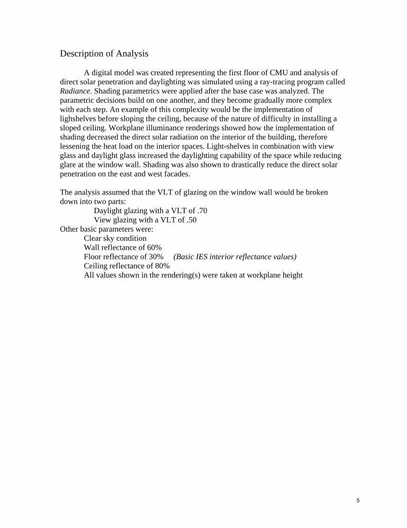
Base Case Workplane Illuminance: D
Direct solar from atrium space
Base Case with thinner exterior columns: Greater solar control with minimal impact on daylight distribution
6
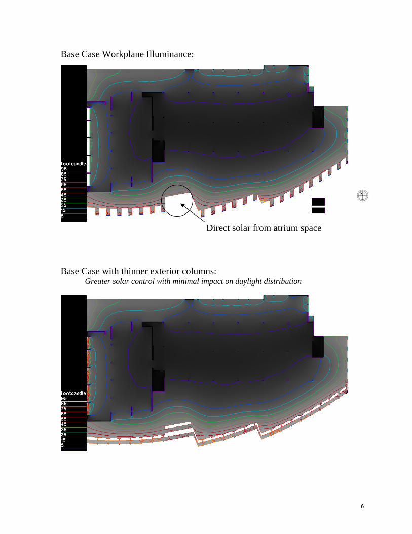
Base Case with horizontal shading on the exterior: Better daylight distribution
Base Case with exterior shading and an interior light shelf: Maximum solar control w/ increased daylight distribution
7
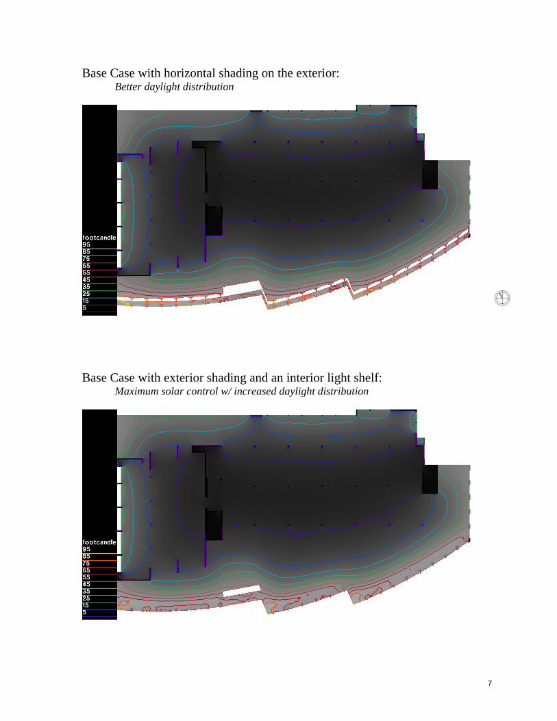
Base Case with additional parametric of a 5 degree sloped ceiling: Maximum solar control w/ increased daylight distribution
Base case with a 10 degree sloped ceiling: Maximum solar control w/ slightly less daylight distribution
8
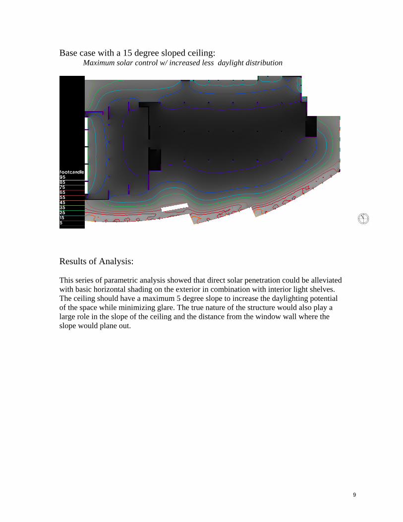
Base case with a 15 degree sloped ceiling: Maximum solar control w/ increased less daylight distribution
Results of Analysis: This series of parametric analysis showed that direct solar penetration could be alleviated with basic horizontal shading on the exterior in combination with interior light shelves. The ceiling should have a maximum 5 degree slope to increase the daylighting potential of the space while minimizing glare. The true nature of the structure would also play a large role in the slope of the ceiling and the distance from the window wall where the slope would plane out.
9
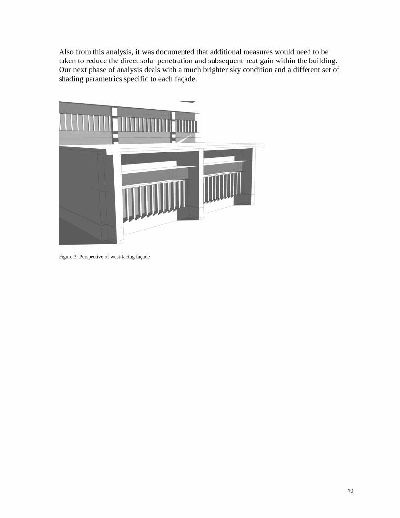
Also from this analysis, it was documented that additional measures would need to be taken to reduce the direct solar penetration and subsequent heat gain within the building. Our next phase of analysis deals with a much brighter sky condition and a different set of shading parametrics specific to each façade.
Figure 3: Perspective of west-facing façade
10
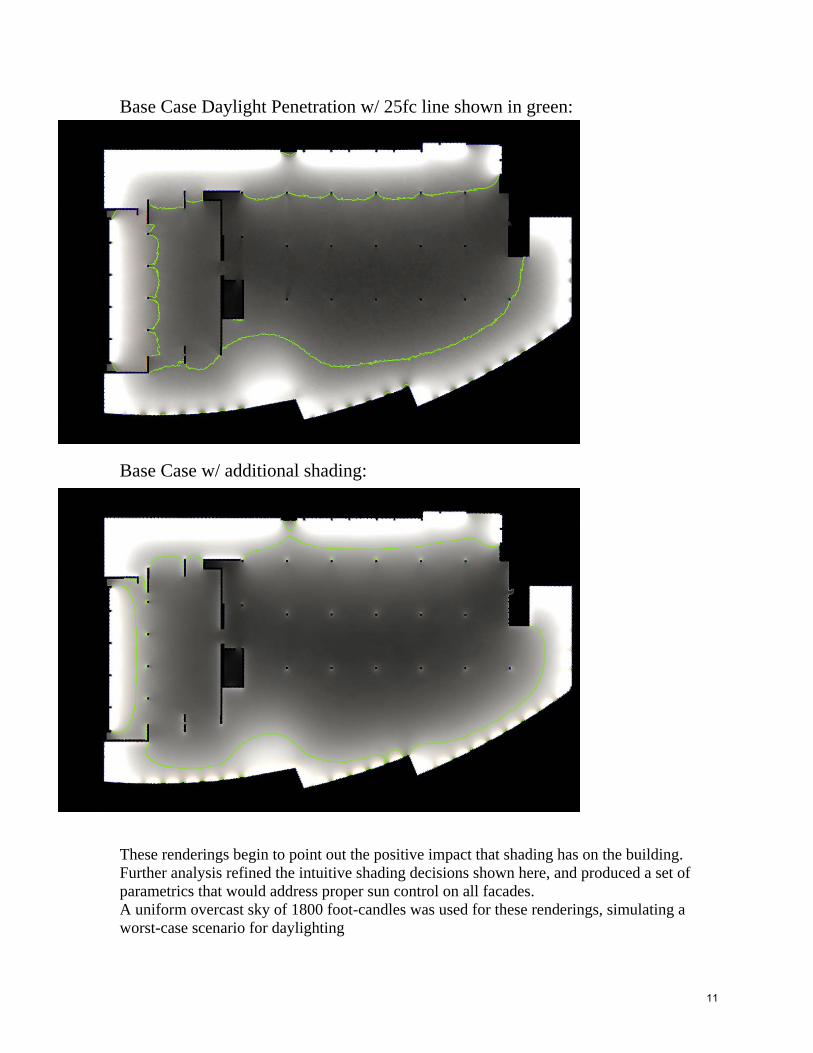
Base Case Daylight Penetration w/ 25fc line shown in green: Base Case w/ additional shading: These renderings begin to point out the positive impact that shading has on the building. Further analysis refined the intuitive shading decisions shown here, and produced a set of parametrics that would address proper sun control on all facades. A uniform overcast sky of 1800 foot-candles was used for these renderings, simulating a worst-case scenario for daylighting
11
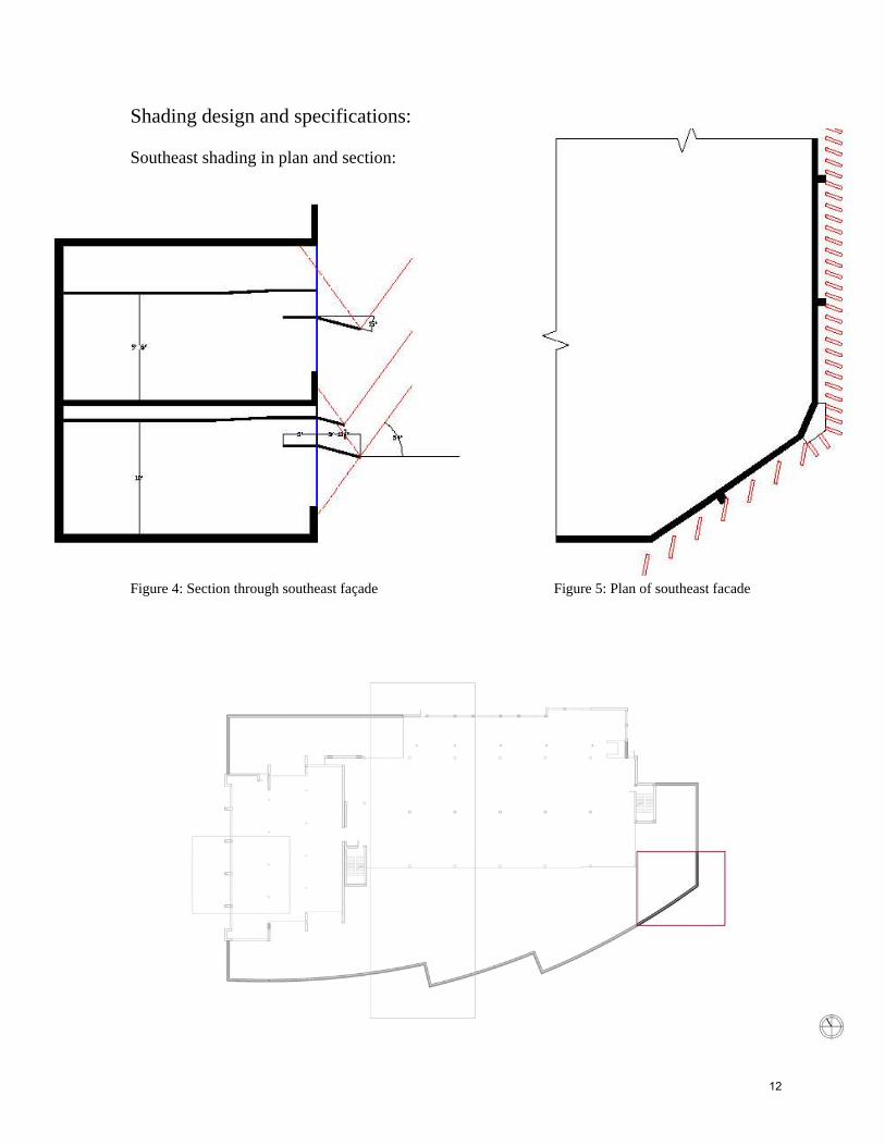
Shading design and specifications: Southeast shading in plan and section: Figure 4: Section through southeast façade Figure 5: Plan of southeast facade
12

Shading design and specifications: West façade shading in plan and section: Figure 6: Section through west façade Figure 7: Plan of west facade
13
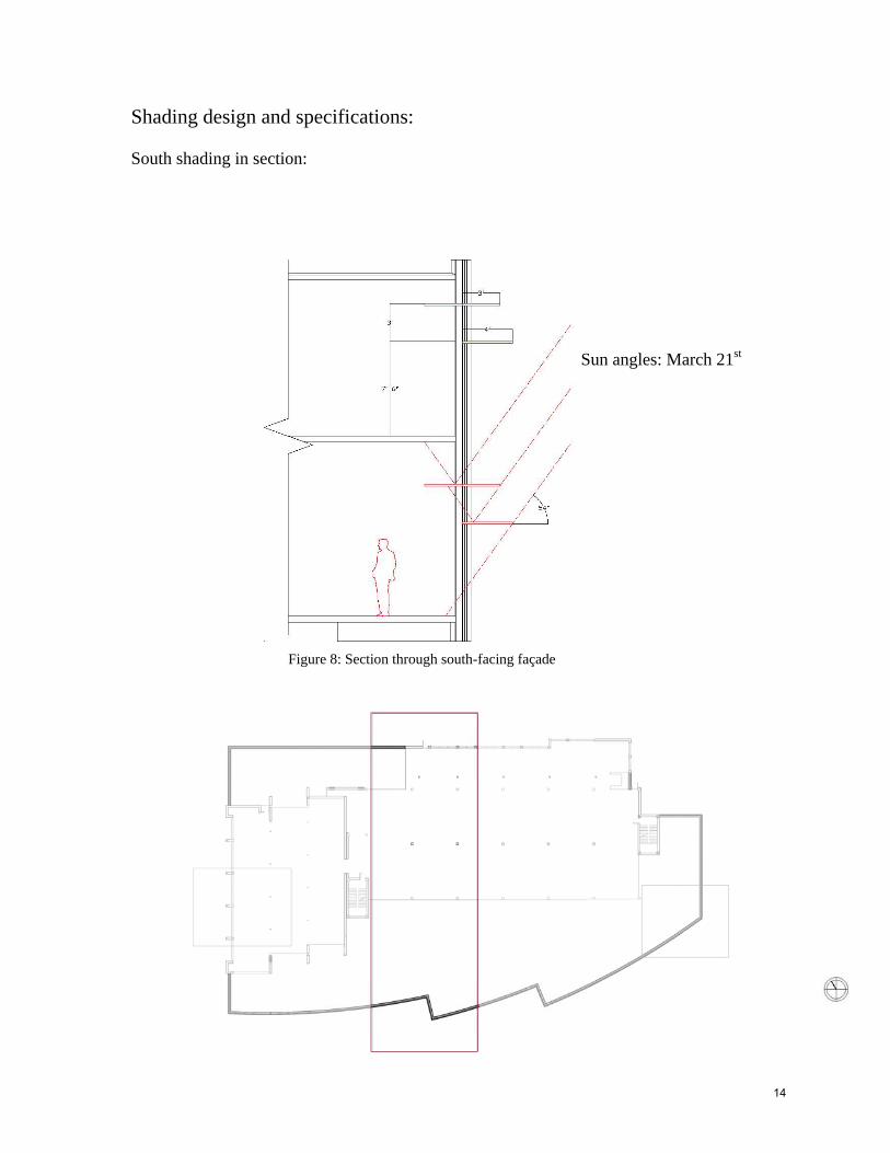
Shading design and specifications: South shading in section: Sun angles: March 21st Figure 8: Section through south-facing façade
14
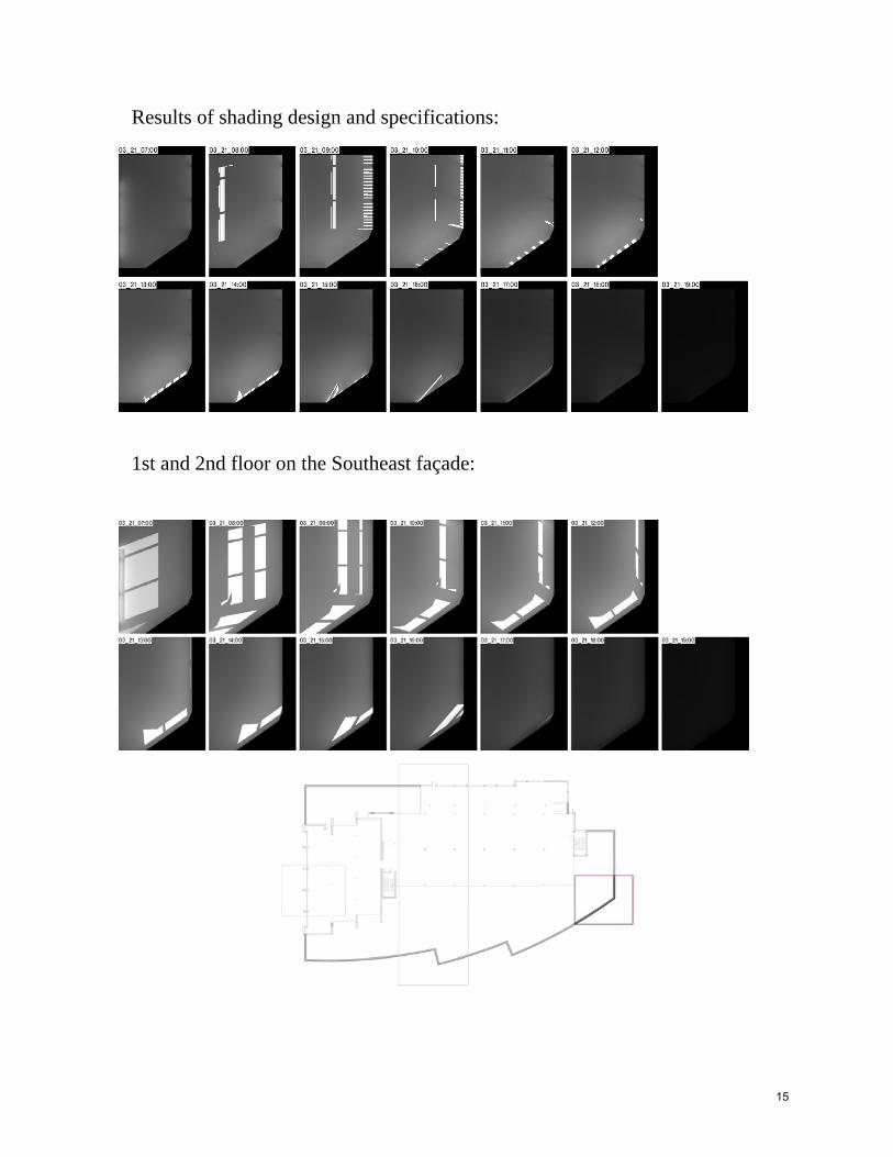
Results of shading design and specifications: 1st and 2nd floor on the Southeast façade:
15
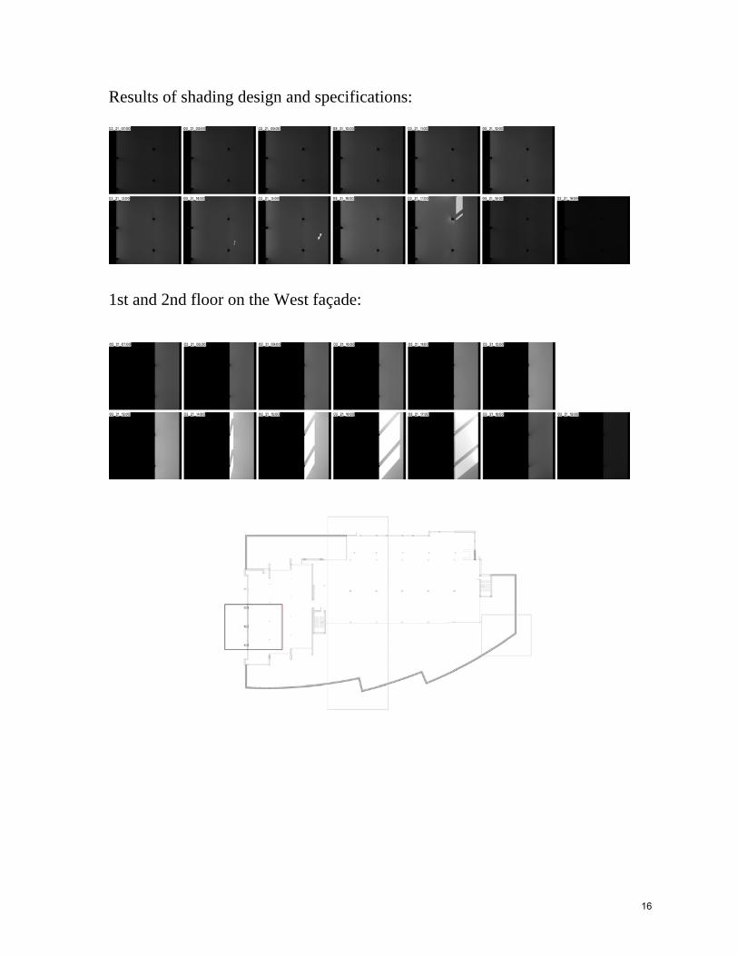
Results of shading design and specifications: 1st and 2nd floor on the West façade:
16
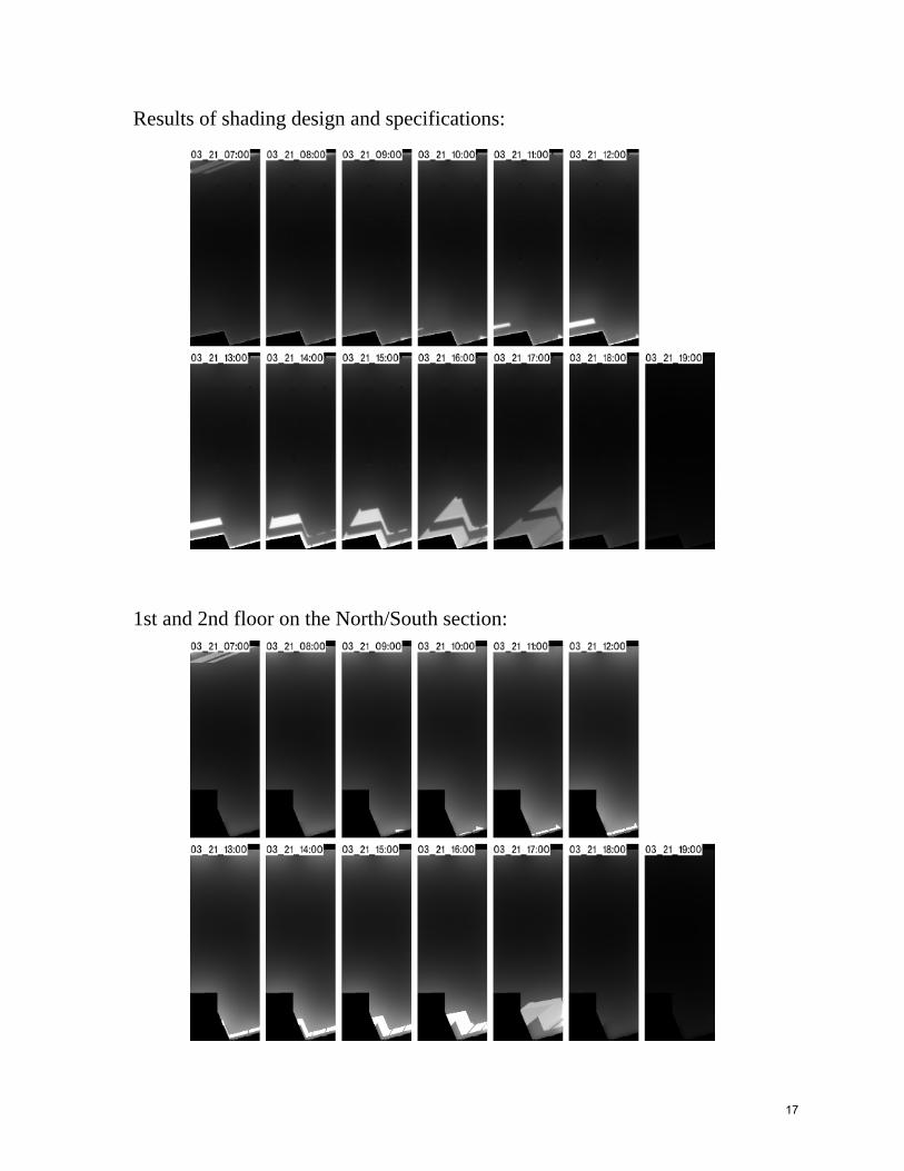
Results of shading design and specifications: 1st and 2nd floor on the North/South section:
17
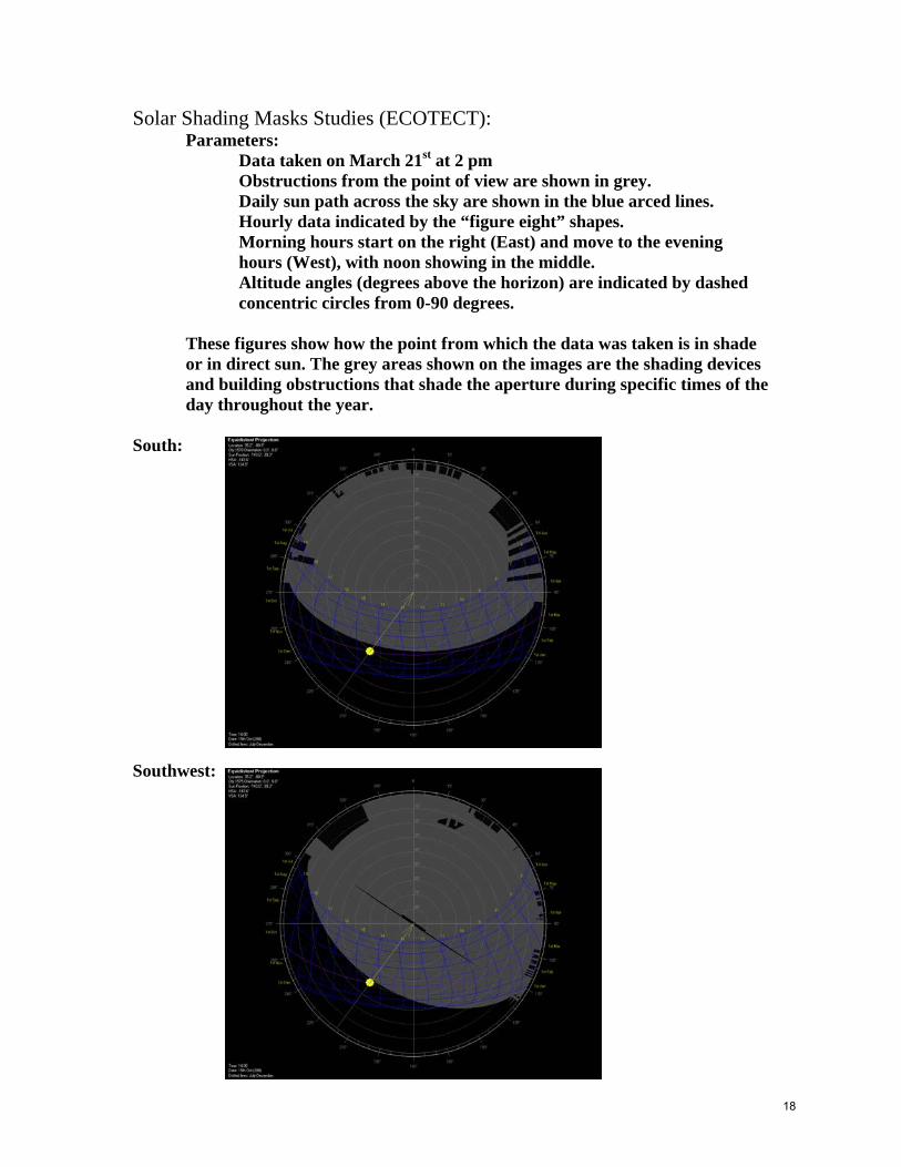
Solar Shading Masks Studies (ECOTECT): Parameters:
Data taken on March 21st at 2 pm Obstructions from the point of view are shown in grey. Daily sun path across the sky are shown in the blue arced lines. Hourly data indicated by the “figure eight” shapes.
Morning hours start on the right (East) and move to the evening hours (West), with noon showing in the middle. Altitude angles (degrees above the horizon) are indicated by dashed concentric circles from 0-90 degrees.
These figures show how the point from which the data was taken is in shade or in direct sun. The grey areas shown on the images are the shading devices and building obstructions that shade the aperture during specific times of the day throughout the year.
South: Southwest:
18
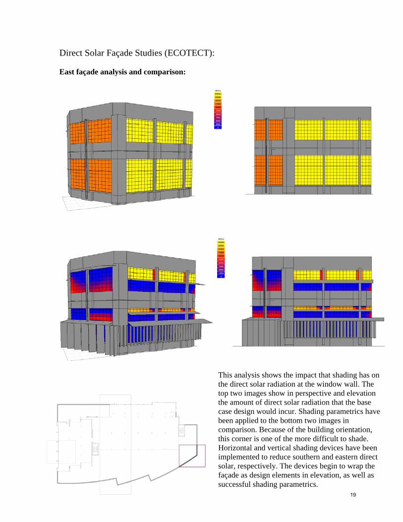
Direct Solar Façade Studies (ECOTECT): East façade analysis and comparison:
This analysis shows the impact that shading has on the direct solar radiation at the window wall. The top two images show in perspective and elevation the amount of direct solar radiation that the base case design would incur. Shading parametrics have been applied to the bottom two images in comparison. Because of the building orientation, this corner is one of the more difficult to shade. Horizontal and vertical shading devices have been implemented to reduce southern and eastern direct solar, respectively. The devices begin to wrap the façade as design elements in elevation, as well as successful shading parametrics.
19
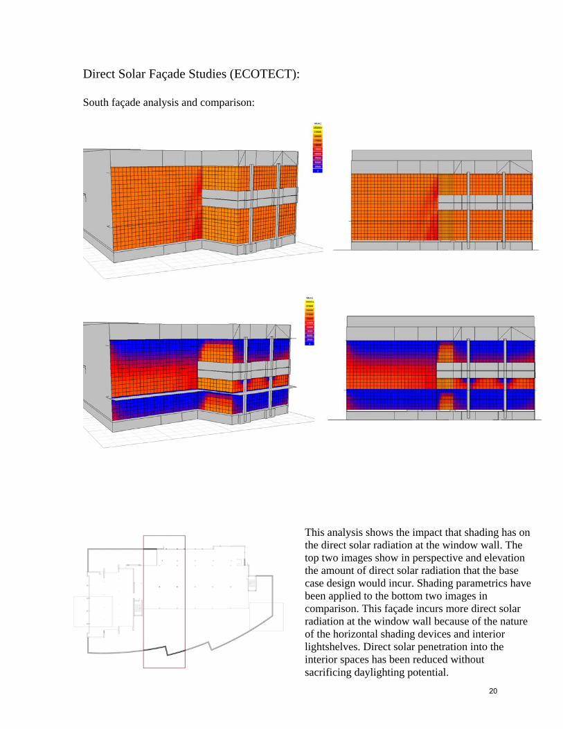
Direct Solar Façade Studies (ECOTECT): South façade analysis and comparison:
This analysis shows the impact that shading has on the direct solar radiation at the window wall. The top two images show in perspective and elevation the amount of direct solar radiation that the base case design would incur. Shading parametrics have been applied to the bottom two images in comparison. This façade incurs more direct solar radiation at the window wall because of the nature of the horizontal shading devices and interior lightshelves. Direct solar penetration into the interior spaces has been reduced without sacrificing daylighting potential.
20
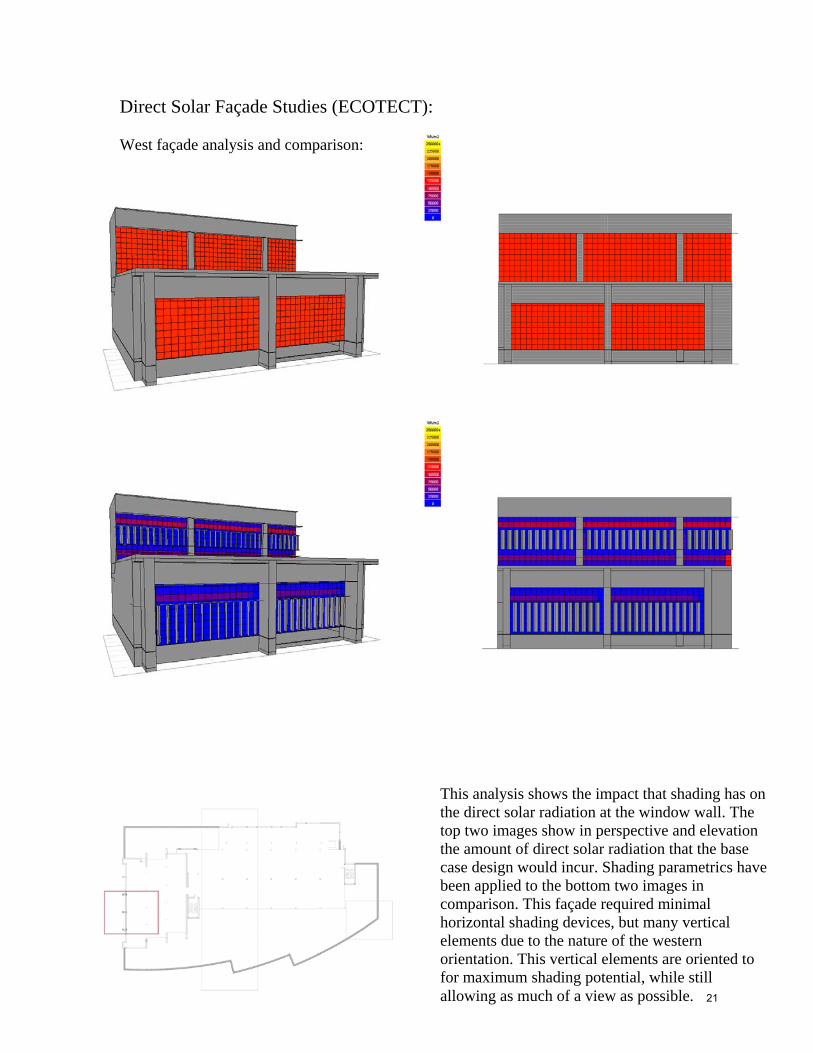
Direct Solar Façade Studies (ECOTECT): West façade analysis and comparison:
This analysis shows the impact that shading has on the direct solar radiation at the window wall. The top two images show in perspective and elevation the amount of direct solar radiation that the base case design would incur. Shading parametrics have been applied to the bottom two images in comparison. This façade required minimal horizontal shading devices, but many vertical elements due to the nature of the western orientation. This vertical elements are oriented to for maximum shading potential, while still allowing as much of a view as possible. 21

Summary of analysis: As currently shown, the building is allowing too much direct solar penetration which calls for shading on the south, east, and west facades.The analysis shown in the previous pages illustrates the positive impact of proper shading devices and light shelves. These parametric assessments of shading elements have informed the options for elevation design as well as how to lay out building program in relation to the window wall. Different shading configurations were used on the different elevations in a response to the changing conditions due to the nature of the building’s solar orientation. Vertical shading elements were shown to be the most effective on both the east and west elevations, and horizontal elements were the most successful on the southern elevation. The southern horizontal shading wraps the building on the east façade and provides a visual connection from the front to the side of the building. It also provides a much-needed response to the southern sun that begins to directly affect the southeast corner of the building. Direct solar penetration has been largely alleviated on all facades where shading devices were implemented. The areas that are still affected by direct solar penetration are minimal, and the worst penetration occurs outside of the standard working day, and thus less of an issue. The reduction in direct solar penetration at the view window also drastically reduces glare at the view window, and lessens the strain on the occupant’s eyes. Since glare has been reduced at the window wall, there is less of a contrast between the interior and exterior spaces near the window wall, which improves the conditions for the occupants within the spaces near the window wall.
22