Charleston Water System
246
Minimum Standards When printed, this document is uncontrolled Charleston Water System MINIMUM STANDARDS FOR THE DESIGN & CONSTRUCTION OF WATER AND WASTEWATER SYSTEMS
Transcript of Charleston Water System

Minimum Standards When printed, this document is uncontrolled
Charleston Water System
MINIMUM STANDARDS FOR THE DESIGN & CONSTRUCTION
OF WATER AND WASTEWATER SYSTEMS
TOC-1 TOC (Rev. 07/09/18) When printed, this document is uncontrolled
MINIMUM STANDARDS FOR THE DESIGN & CONSTRUCTION OF WATER AND WASTEWATER SYSTEMS
TABLE OF CONTENTS
1. Introduction (Rev. 06/02/17) ................................................................................................ 1-1 2. Roles & Responsibilities (Rev. 06/02/17) A. Charleston Water System ..................................................................................................... 2-1 B. Developer .............................................................................................................................. 2-2 C. Developer’s Engineer ............................................................................................................ 2-3 3. Submittals and Approvals (Rev. 07/09/18) A. General Information ............................................................................................................... 3-1 B. Water and Wastewater Service Availability ............................................................................ 3-2 C. Preliminary Fee Determination ............................................................................................. 3-3 D. Plan Review .......................................................................................................................... 3-4 E. Plan Approval ........................................................................................................................ 3-7 F. Construction Activity .............................................................................................................. 3-8 G. Final Inspection ................................................................................................................... 3-10 H. Record Drawings and Valve Cards ...................................................................................... 3-12 I. Project Closeout .................................................................................................................. 3-15 J. Commissioning .................................................................................................................... 3-20 K. Application for New Services ............................................................................................... 3-22 L. Project Cancellation ............................................................................................................ 3-23 Attachments to Section 3 (Available on the New Development page on our website) Checklists: Closeout Checklist Water ................................................................................... (Rev. 07/02/17) Closeout Checklist Wastewater .......................................................................... (Rev. 08/01/17) Record Drawing Checklist Water ........................................................................ (Rev. 07/09/18) Record Drawing Checklist Wastewater Gravity Sewer Only ............................... (Rev. 07/09/18) Record Drawing Checklist Wastewater Gravity Sewer with FM and PS .............. (Rev. 07/09/18) Valve Card Checklist Water ................................................................................ (Rev. 06/02/17) Valve Card Checklist Wastewater....................................................................... (Rev. 06/02/17) Easement Plat Checklist ..................................................................................... (Rev. 06/02/17) Legal Documents: Bill of Sale Water ................................................................................................ (Rev. 06/02/17) Bill of Sale Wastewater ....................................................................................... (Rev. 06/02/17) Affidavit of Title Water ........................................................................................ (Rev. 06/02/17) Affidavit of Title Wastewater ............................................................................... (Rev. 06/02/17)
TOC-2 TOC (Rev. 07/09/18) When printed, this document is uncontrolled
Affidavit for Transfer of Real Property ................................................................. (Rev. 06/02/17) Title to Real Estate ............................................................................................. (Rev. 06/02/17) Affidavit for Exempt Transfer .............................................................................. (Rev. 05/01/17) Maintenance Agreement Water .......................................................................... (Rev. 06/02/17) Maintenance Agreement Wastewater ................................................................. (Rev. 06/02/17) Financial Documents: Sample - Irrevocable Standby Letter of Credit .................................................... (Rev. 08/01/17) Easement Agreement: ...................................................................................... (Rev. 06/02/17) 4. Easements (Rev. 06/02/17) A. General Information ............................................................................................................... 4-1 B. Easement Width .................................................................................................................... 4-1 C. Easement Plat ....................................................................................................................... 4-3 D. Easement Agreement ............................................................................................................ 4-3 5. Development Fees (Rev. 06/02/17) A. General Information ............................................................................................................... 5-1 B. Tap and Impact Fees............................................................................................................. 5-1 C. Engineering Services Fee Deposit......................................................................................... 5-3 D. Maintenance Agreement Bond .............................................................................................. 5-3 E. Maintenance Agreement Final Inspection Fee ....................................................................... 5-3 F. Origination Fee ...................................................................................................................... 5-4 G. Impact Fee Reimbursement .................................................................................................. 5-4 H. Engineering Services Fee Reimbursement ............................................................................ 5-4 I. Other Fees ............................................................................................................................ 5-4 6. Water Distribution System Design Standards (Rev. 07/09/18) A. General ................................................................................................................................ 6-1 B. Design Criteria....................................................................................................................... 6-1 C. Capacity Design .................................................................................................................... 6-3 D. Relation to Sewer Mains ........................................................................................................ 6-8 E. Relation to Storm Drains ....................................................................................................... 6-8 F. Services .............................................................................................................................. 6-10 G. Joint Restraint ..................................................................................................................... 6-12 H. Valves ................................................................................................................................. 6-12 I. Fire Hydrants ....................................................................................................................... 6-13 J. Blow-Off Assemblies ........................................................................................................... 6-14

TOC-3 TOC (Rev. 07/09/18) When printed, this document is uncontrolled
7. Water Distribution System Materials for Construction (Rev. 07/09/18) A. General ................................................................................................................................ 7-1 B. Bedding Material ................................................................................................................... 7-1 C. Ductile Iron Pipe .................................................................................................................... 7-2 D. Ductile Iron Pipe Joints .......................................................................................................... 7-2 E. Ductile Iron Pipe Fittings ........................................................................................................ 7-5 F. Tapping Sleeves .................................................................................................................... 7-6 G. Valves .................................................................................................................................. 7-6 H. Fire Hydrants ....................................................................................................................... 7-12 I. Polyethylene Encasement ................................................................................................... 7-14 J. Metallic Detection Tape ....................................................................................................... 7-14 K. Services .............................................................................................................................. 7-15 8. Water Distribution System Construction Procedures (Rev. 07/09/18) A. General ................................................................................................................................ 8-1 B. Operation of Charleston Water System Valves and Hydrants ................................................ 8-1 C. Handling of Materials ............................................................................................................. 8-2 D. Trench Excavation ................................................................................................................. 8-2 E. Trench Backfill ....................................................................................................................... 8-3 F. Pipe and Appurtenances ....................................................................................................... 8-4 G. Tie-in to Existing Mains ......................................................................................................... 8-7 H. Setting Valves and Valve Boxes ............................................................................................ 8-8 I. Installation of Air Release Valves .......................................................................................... 8-8 J. Fire Hydrants ......................................................................................................................... 8-9 K. Services .............................................................................................................................. 8-10 L. Hydrostatic Testing .............................................................................................................. 8-12 M. Disinfection ......................................................................................................................... 8-14 9. Wastewater Collection System Gravity Sewer Design Standards (Rev. 07/09/18) A. General ................................................................................................................................. 9-1 B. Design Criteria.................................................................................................................... ...9-1 C. Capacity Design .................................................................................................................... 9-3 D. Relation to Water Mains ........................................................................................................ 9-3 E. Relation to Storm Drains ....................................................................................................... 9-4 F. Services ................................................................................................................................ 9-6 G. Manholes ............................................................................................................................... 9-7 10. Wastewater Collection System Gravity Sewer Materials for Construction (Rev. 07/09/18) A. General ............................................................................................................................... 10-1 B. Pipe and Fittings .................................................................................................................. 10-1 C. Metallic Detection Tape ....................................................................................................... 10-3 D. Manholes ............................................................................................................................. 10-3

TOC-4 TOC (Rev. 07/09/18) When printed, this document is uncontrolled
E. Pipe and Manhole Foundation and Backfill Materials .......................................................... 10-7 11. Wastewater Collection System Gravity Sewer Construction Procedures (Rev. 07/09/18) A. General ............................................................................................................................... 11-1 B. Handling of Materials ........................................................................................................... 11-1 C. Pipe Cutting ......................................................................................................................... 11-2 D. Trench Excavation ............................................................................................................... 11-2 E. Trench Backfill ..................................................................................................................... 11-3 F. Pipe Installation ................................................................................................................... 11-4 G. Connections to Existing Mains ............................................................................................. 11-5 H. Manholes ............................................................................................................................. 11-6 I. Services .............................................................................................................................. 11-7 J. Testing ................................................................................................................................ 11-8 K. Closed Circuit Television (CCTV) Inspection ..................................................................... 11-16 12. Wastewater Collection System Force Main Design Standards (Rev. 07/09/18) A. General ............................................................................................................................... 12-1 B. Design Criteria..................................................................................................................... 12-1 C. Capacity Design .................................................................................................................. 12-2 D. Separation of Water Mains and Force Mains ....................................................................... 12-2 E. Cover .................................................................................................................................. 12-2 F. Connection to an Existing Gravity System ........................................................................... 12-3 G. Connection to an Existing Force Main ................................................................................. 12-3 H. Valves ................................................................................................................................. 12-3 13. Wastewater Collection System Force Main Materials for Construction (Rev. 07/09/18) A. General ............................................................................................................................... 13-1 B. Pipe and Fittings .................................................................................................................. 13-1 C. Metallic Detection Tape ....................................................................................................... 13-6 D. Tracer Wire ......................................................................................................................... 13-6 E. Air Release Valves .............................................................................................................. 13-6 F. Cushioned Swing Check Valves .......................................................................................... 13-8 G. Plug Valves ......................................................................................................................... 13-8 14. Wastewater Collection System Force Main Construction Procedures (Rev. 07/09/18) A. General ............................................................................................................................... 14-1 B. Operation of Charleston Water System Valves .................................................................... 14-1 C. Handling of Materials ........................................................................................................... 14-2 D. Trench Excavation ............................................................................................................... 14-3 E. Trench Backfill ..................................................................................................................... 14-4 F. Pipe, Valve and Appurtenance Installation… ....................................................................... 14-5 G. Connection to an Existing Gravity System ........................................................................... 14-8

TOC-5 TOC (Rev. 07/09/18) When printed, this document is uncontrolled
H. Connection to an Existing Force Main ................................................................................. 14-9 I. Installation of Air Release Valves ........................................................................................ 14-9 J. Installation of Cushioned Swing Check Valves .................................................................. 14-10 K. Installation of Plug Valves ................................................................................................. 14-10 L. Metallic Detection Tape ..................................................................................................... 14-10 M. Tracer Wire Installation ...................................................................................................... 14-11 N. Jack and Bore ................................................................................................................... 14-11 O. Hydrostatic Testing… ........................................................................................................ 14-16 15. Wastewater Collection System Pump Station Design Standards (Rev. 07/09/18) A. General ............................................................................................................................... 15-1 B. Capacity Design .................................................................................................................. 15-1 C. Pump Station Design ........................................................................................................... 15-1 16. Wastewater Collection System Pump Station Materials for Construction (Rev. 07/09/18) A. General ............................................................................................................................... 16-1 B. Wetwells .............................................................................................................................. 16-1 C. Primary Level Control System ............................................................................................. 16-2 D. Backup Level Control System .............................................................................................. 16-2 E. Piping and Fittings ............................................................................................................... 16-3 F. Valves ................................................................................................................................. 16-4 G. SCADA Radio Antenna and Antenna Pole .......................................................................... 16-7 H. Fencing ............................................................................................................................... 16-7 I. Station Security Light........................................................................................................... 16-8 J. Pump Station Sign ............................................................................................................... 16-8 K. Submersible Pump Station .................................................................................................. 16-9 L. Self-priming Pump Station ................................................................................................. 16-21 M. Grinder Pump Station ........................................................................................................ 16-29 17. Wastewater Collection System Pump Station Construction Procedures (Rev. 07/09/18) A. General ............................................................................................................................... 17-1 B. Operation of Charleston Water System Valves .................................................................... 17-1 C. Handling of Materials ........................................................................................................... 17-1 D. Wetwell ............................................................................................................................... 17-2 E. Level Controls ..................................................................................................................... 17-4 F. Piping and Fittings ............................................................................................................... 17-4 G. Valves ................................................................................................................................. 17-5 H. SCADA Radio Antenna and Antenna Pole .......................................................................... 17-6 I. Fencing ............................................................................................................................. 17-10 J. Asphalt .............................................................................................................................. 17-11 K. Submersible Pump Station ................................................................................................ 17-11 L. Self-Priming Pump Station................................................................................................. 17-14

1-1 EC-MGT-2 (Rev. 06/02/17) When printed, this document is uncontrolled.
SECTION 1
INTRODUCTION An increase in development in Charleston and rapid expansion of the water and wastewater systems for the Commissioners of Public Works of the City of Charleston, SC (D.B.A. Charleston Water System) has resulted in the need for a quality standard for those systems being deeded to or constructed for Charleston Water System. The benefits of standardization for Charleston Water System include:
A reduction in overall cost of operations and maintenance
A reduction in the total inventory of spare or replacement components
Familiarity with systems resulting in reduced down time during emergencies These standards have been adopted by the Board of Commissioners and incorporated into a single document titled Minimum Standards for the Design & Construction of Water and Wastewater Systems (a.k.a. Minimum Standards). The Minimum Standards are maintained on the New Development Page on our website www.charlestonwater.com and shall be utilized in the design and construction of all water and wastewater systems within the boundaries of Charleston Water System’s service area. For document management purposes, the Minimum Standards are divided into numbered sections with each section having its own revision date. Notifications of revision are posted on our website. You may also click here to sign up to receive email and/or text message notifications of all changes affecting Charleston Water System’s Development Policies, including revisions to the Minimum Standards. If you have any questions concerning Charleston Water System’s Minimum Standards for the Design & Construction of Water and Wastewater Systems or Development Policies, please contact Charleston Water System’s New Development Program Manager at (843) 727-6869. ISO 14001 Certification – Awareness of Charleston Water System’s Environmental Policy Charleston Water System is certified under ISO 14001, the International Standard for Environmental Management. Through our environmental management system, we prevent pollution, protect public health, and adhere to all legal and other requirements. All firms doing work for Charleston Water System must adhere to our policies, which require strict adherence to all permits, regulations, and procedures in order to prevent any adverse impact to the environment. Deviation could result in disapproved work. To learn more about our environmental management system and ISO 14001 certification, please visit our website.

2-1 EC-MGT-3 (Rev. 06/02/17) When printed, this document is uncontrolled.
SECTION 2
ROLES & RESPONSIBILITIES The following information covers the roles and responsibilities of the parties involved in the submittal and approval process for new water and wastewater systems and is applicable to all developments requiring water and/or wastewater service from Charleston Water System. A. CHARLESTON WATER SYSTEM
1. Charleston Water System New Development Program staff will:
a. Determine water and/or wastewater service availability
b. Perform hydrostatic flow test at the request of the Developer or the
Developer’s Engineer
c. Determine all applicable fees
d. Review plans and permit applications for conformance with the requirements of these standards
e. Review and submit Developer Engineer’s prepared encroachment
permits
f. Identify to the Developer and the Developer’s Engineer any required changes when plans are not in conformance with the requirements of these standards
g. Prepare and execute a Development Agreement
h. Under the Delegated Review Program, submit the approved permit
application package, as prepared by the Developer’s Engineer, to the South Carolina Department of Health and Environmental Control (SC DHEC) for a Permit to Construct
i. Upon receipt of a SC DHEC Permit to Construct, distribute plans
stamped “Approved for Installation”
2. Charleston Water System Construction Inspection staff will:
a. Observe construction related activities to ensure compliance with the requirements of these standards, approved plans and applicable permits

2-2 EC-MGT-3 (Rev. 06/02/17) When printed, this document is uncontrolled.
b. Require work determined not to be in compliance with these standards, approved plans and applicable permits, to be corrected to the satisfaction of Charleston Water System
c. Review and approve project Record Drawings and Valve Cards
d. Perform a Project Commissioning for acceptance of the constructed
water and/or wastewater systems
3. Charleston Water System Asset Management staff will: a. Review and approve project closeout documents
b. Provide final Operation and Maintenance (O&M) letter(s) to SC
DHEC
c. Submit a Service Acceptance notification to Charleston Water System’s Customer Service Department
B. DEVELOPER
1. The Developer shall be considered the person or entity initiating the development of a new residential or commercial property. This can be, but is not required to be, the Owner of the property. This person or entity shall have legal authority to execute necessary permits, applications, and legal documents which require the Owner’s signature. This same person or entity will execute all documents throughout the project unless the project is sold and this authority is transferred to the new Owner.
2. The Developer will:
a. Provide accurate information as to the person or entity responsible
for the development and their contact information b. Be responsible for payment of all fees required in accordance with
these standards
c. Execute the Development Agreement
d. Be responsible for the execution of all documents required for project closeout
e. Be financially responsible for future requests for repairs, if any arise, during the maintenance agreement period after takeover of the constructed system(s) by Charleston Water System

2-3 EC-MGT-3 (Rev. 06/02/17) When printed, this document is uncontrolled.
f. Ensure water and/or wastewater contractor is a Charleston Water System Approved Contractor. Charleston Water System will not consider any contractor to be added to the Approved Contractor list after the date plans are “Approved for Installation”.
C. DEVELOPER’S ENGINEER
1. The Developer’s Engineer is the Engineer hired by the Developer or Property Owner to prepare plans for the extension of water and/or wastewater infrastructure.
2. The Developer’s Engineer will:
a. Request determination of water and/or wastewater service availability
b. Request hydrostatic flow test for all water projects
c. Prepare and submit plans to Charleston Water System in accordance with the requirements of these standards
d. Ensure plans are consistent with Charleston Water System’s long-
term master plans
e. Make revisions to the plans in accordance with Charleston Water System’s requirements
f. Under the Delegated Review Program, submit to Charleston Water
System the SC DHEC permit application package
g. Submit to Charleston Water System all encroachment permit applications
h. Ensure water and/or wastewater contractor is a Charleston Water
System Approved Contractor. Charleston Water System will not consider any contractor to be added to the Approved Contractor list after the date plans are “Approved for Installation”.
i. Schedule Pre-Construction Meeting with the assigned Charleston
Water System Construction Inspector prior to beginning construction
j. Monitor all phases of the work in progress during construction
k. Conduct required testing of systems in the presence of Charleston Water System’s Construction Inspector
2-4 EC-MGT-3 (Rev. 06/02/17) When printed, this document is uncontrolled.
l. Promptly notify Charleston Water System concerning any changes which may be necessary during the progress of the work; no changes to the approved plans shall be performed without prior written approval from Charleston Water System
m. Certify the work performed is in accordance with the approved plans and these standards
n. Schedule a Final Inspection and Commissioning with the assigned Charleston Water System Construction Inspector to determine conformance with the “Approved for Installation” plans
o. Provide all information and submittals as required for project
completion and takeover as defined in Section 3 of these standards

3-1 EC-MGT-4 (Rev. 07/09/18) When printed, this document is uncontrolled.
SECTION 3
SUBMITTALS AND APPROVALS The following information covers the submittal and approval process for new water and wastewater systems and is applicable to all developments requiring water and/or wastewater service from Charleston Water System. No deviation from this process will be allowed without the expressed written consent of Charleston Water System. A. GENERAL INFORMATION
1. Charleston Water System will consider for operation and maintenance only those water and wastewater systems which are within the boundaries of the Charleston Water System service area.
2. Design and construction of water and wastewater systems shall be in
accordance with these standards.
3. Construction of water and wastewater systems to be turned over to Charleston Water System must be performed by a Charleston Water System Approved Contractor. The Approved Contractor lists for both Large Projects (those greater than $50,000) and Small Projects (those $50,000 and less) are available on the New Development page of our website. Requirements for being considered an Approved Contractor can be obtained by contacting the Assistant Director of Engineering and Construction by email at [email protected] or by telephone at (843) 727-6876.
4. All connections to Charleston Water System’s existing water and
wastewater systems must be approved and inspected by Charleston Water System.
5. No water or wastewater system shall be put into service, nor will any service
application be accepted, prior to the receipt of all approved project closeout documents, applicable fees, and the Permit to Operate as issued by the South Carolina Department of Health and Environmental Control (SC DHEC).
6. Charleston Water System has specific requirements and specifications for
the selection and installation of backflow prevention assemblies. As part of Plan Review, the Cross Connection Control Program Manager will review the plans and make an assessment of the backflow requirements for the project. Information regarding Charleston Water System’s backflow prevention requirements is available on the New Development page of our

3-2 EC-MGT-4 (Rev. 07/09/18) When printed, this document is uncontrolled.
website or by contacting the Cross Connection Control Program Manager at (843) 727-7216.
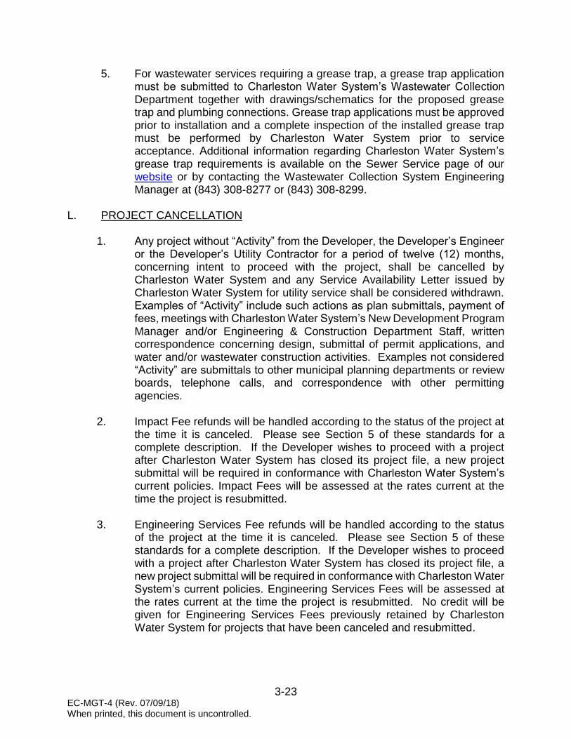
7. Charleston Water System has specific requirements for grease traps. As a
part of Plan Review, Charleston Water System’s Wastewater Collection Department will review plans for compliance with all great trap requirements. For all services requiring a grease trap, a Grease Trap Application must be submitted to Charleston Water System’s Wastewater Collection Department together with drawings/schematics for the proposed grease trap and plumbing connections. Grease Trap Applications must be approved prior to installation and a complete inspection of the installed grease trap must be performed by Charleston Water System prior to service acceptance. Additional information regarding Charleston Water System’s grease trap requirements is available on the Sewer Service page of our website or by contacting the Wastewater Collection System Engineering Manager at (843) 308-8277 or (843) 308-8299.
8. Developers, Designers, Planners, Engineers and others associated with
implementing projects are strongly encouraged to meet with Charleston Water System’s Engineering & Construction Department to review plans and coordinate proposed projects with Charleston Water System’s long-term master plans. An appointment can be made by contacting Charleston Water System’s New Development Program Manager at (843) 727-6869.
9. Prior to designing water and wastewater systems, the Developer and the
Developer’s Engineer are encouraged to take into careful consideration all Charleston Water System Development Policies.
10. A full description of Charleston Water System’s fees can be found in Section
5 of these standards. Charleston Water System’s fees are subject to review by the Commissioners and may be amended from time to time.
11. Project submittals are to be sent to Charleston Water System at the
following address:
New Development Program Manager Charleston Water System
103 St. Philip Street Charleston, SC 29403
B. WATER AND WASTEWATER SERVICE AVAILABILITY
1. The initial step for any new water or wastewater system being considered
by Charleston Water System is for the Developer or the Developer’s Engineer to complete and submit a Request for Service Availability to determine service availability for the proposed development.

3-3 EC-MGT-4 (Rev. 07/09/18) When printed, this document is uncontrolled.
2. The information provided in the request for the proposed development will be utilized by Charleston Water System to perform a preliminary hydraulic analysis of the proposed water and/or wastewater system.
3. Based on the results and conclusion determined by the preliminary
hydraulic analysis, a Service Availability Letter will be issued by Charleston Water System stating whether service is available or is not available for the proposed development.
4. A Service Availability Letter will be valid for 12 months from the date of
issuance.
5. Any subsequent changes to the proposed development deemed significant by Charleston Water System may invalidate the Service Availability Letter and necessitate submission of a new Request for Service Availability.
6. No Preliminary Fee Determination or Plan Review will be conducted without
a valid Service Availability Letter stating Charleston Water System’s willingness and ability to provide water and/or wastewater service.
C. PRELIMINARY FEE DETERMINATION
1. Upon receipt of a Service Availability Letter, the Developer or the Developer’s Engineer shall submit a Preliminary Fee Determination package to Charleston Water System’s New Development Program Manager. The package shall include the following items (in hard copy or digital format) or Preliminary Fee Determination will not proceed:
a. A valid Water and/or Wastewater Service Availability Letter b. Completed Preliminary Fee Determination Worksheet
c. One (1) copy of water and/or wastewater system plans
d. One (1) copy of demolition plans, if applicable
e. Water and/or wastewater calculations. Provide copy of Charleston
Water System hydrostatic flow test results.
f. Completed Asset Inventory Worksheet (submitted digitally in Excel format) showing Developer Engineer’s line item cost estimate for the water and wastewater assets to be turned over to Charleston Water System at the end of the project. Cost estimates should reflect, in general, all expenses associated with bringing the assets into service.
3-4 EC-MGT-4 (Rev. 07/09/18) When printed, this document is uncontrolled.
2. In return, the New Development Program Manager will provide to the Developer and the Developer’s Engineer a Preliminary Fee Determination for the following:
a. Engineering Services Fee Deposit b. Impact Fees
c. Tap Fees
d. Description of Project Closeout Fees
3. For a full description of fees refer to Section 5 of these standards.
D. PLAN REVIEW
1. Project Types a. Main Extension Projects
Main extension projects are defined as those projects that require the extension of a water or wastewater main to provide service and/or fire protection to the development and typically require a SC DHEC Permit to Construct.
b. Service Only Projects
Service Only Projects are defined as those projects which include fire hydrant installations, dedicated fire services, and commercial and domestic water and wastewater services which do not typically require a SC DHEC Permit to Construct.
c. Dedicated Fire Services
1. A dedicated fire service is defined as an unmetered service to a single structure, without looping or connection to a public or private hydrant, which provides water supply for use in internal fire protection systems only. No commercial, domestic, industrial, or other water uses are allowed.
2. Charleston Water System will only be responsible for operation and maintenance of the dedicated fire service from the Charleston Water System water main to the edge of the right-of-way or easement. See Construction Details.

3-5 EC-MGT-4 (Rev. 07/09/18) When printed, this document is uncontrolled.
3. Any portion of the dedicated fire service that extends beyond the edge of the right-of-way or easement shall be considered private and is the responsibility of the Owner.
4. Any portion of the dedicated fire service that is considered
private and is constructed in the City of Charleston, the underground fire service contractor must obtain a Fire Service Underground Permit from the City of Charleston Fire Department prior to beginning construction.
2. Submittal Requirements and Review Process
a. Upon receipt of the Preliminary Fee Determination, the Developer or
the Developer’s Engineer shall submit a plan review package to Charleston Water System’s New Development Program Manager. The package shall include the following items, or Plan Review will not proceed: 1. Engineering Services Fee Deposit (Required for Main
Extension Projects Only)
2. Four (4) sets of water and/or wastewater system plans drawn to a horizontal scale no smaller than 1-inch equals 50-feet and a vertical scale no smaller than 1-inch equals 5-feet. Plans shall be signed, sealed and dated by an Engineer registered in the state of South Carolina and shall include the following:
a. Complete system design. Include cover sheet, general development plans, building layout plans, drainage plans, landscape plans, and demolition plans along with water and wastewater system plans. Landscape plans shall include any proposed hardscapes (i.e., signage, architectural columns, retaining walls or other types of above ground structures). Demolition plans shall include all existing water and wastewater services proposed for abandonment.
b. Plan view for all water and wastewater projects.
c. Profile for wastewater gravity sewer mains.
d. Profile for all water mains 10-inch and larger.
e. Profile for all water mains on Peninsula Charleston, regardless of main size. Peninsula Charleston shall be defined as the areas south of Mount Pleasant Street.

3-6 EC-MGT-4 (Rev. 07/09/18) When printed, this document is uncontrolled.
f. Profile for all water mains at storm drain crossings.
g. Profile for all water and wastewater mains installed by Jack and Bore or Horizontal Directional Drill or where steel casing is used.
h. For commercial developments, provide location and
size of all proposed water and wastewater services. i. County Tax Map Reference Number of Property and
information showing Municipality, if one exists. j. All public and private rights-of-way. Plans should
indicate ownership of existing roadways (City, County, or State). Indicate the agency to operate and maintain proposed roadways.
k. All existing and proposed easements and their ownership.
l. Location and width of all existing and proposed
Charleston Water System easements. m. For commercial developments requesting water for
temporary fire protection prior to receipt of a SC DHEC Permit to Operate, provide the following:
1. Location of single point of connection to the
public potable water system. 2. Location of Charleston Water System approved
Reduced Pressure Principle backflow prevention assembly and Charleston Water System approved Fire Service Water Meter. Backflow assembly and meter shall be sized by the Developer’s Engineer to provide the required fire flow. See Construction Details.
3. In cases where the water system plans show
multiple connection points to the public potable water system, indicate on the plans a minimum 3-foot air-gap separation at all other locations.
3. One (1) set of typed or printed water and/or wastewater calculations signed, sealed and dated by an Engineer registered in the state of South Carolina. Calculations shall be in accordance with the requirements set forth in the applicable sections of these standards.

3-7 EC-MGT-4 (Rev. 07/09/18) When printed, this document is uncontrolled.
a. Water Mains – Section 6, Water Distribution System Design Standards. For commercial developments requesting water for temporary fire protection, provide additional fire flow calculations based on the size of the proposed backflow prevention assembly and fire service meter.
b. Wastewater Gravity Sewer Mains – Section 9, Wastewater Collection System Gravity Sewer Design Standards.
c. Wastewater Force Mains - Section 12, Wastewater
Collection System Force Main Design Standards.
d. Wastewater Pump Stations – Section 15, Wastewater Collection System Pump Station Design Standards.
b. Upon review of the submitted plan review items, the assigned
Charleston Water System Engineering Assistant responsible for the plan review will return to the Developer’s Engineer: 1. Written design change requirements and/or one (1) set of
plans indicating necessary corrections.
2. Request for any other required information pertinent to the proposed project.
3. Written notice as to whether a Charleston Water System
Approved Large Projects Contractor or Small Projects Contractor shall be utilized to construct the water and wastewater systems.
4. Backflow review comments; if applicable.
E. PLAN APPROVAL
1. The Developer’s Engineer shall submit to the assigned Charleston Water System Engineering Assistant one (1) set of revised water and/or wastewater system plans based on the design change requirements and corrections identified during Charleston Water System’s initial plan review. Once an acceptable set of plans are approved by Charleston Water System, the Engineering Assistant will notify the Developer’s Engineer in writing.
2. Upon notification of plan approval, the Developer’s Engineer shall submit to
the Charleston Water System Engineering Assistant, the following:

3-8 EC-MGT-4 (Rev. 07/09/18) When printed, this document is uncontrolled.
a. Seven (7) complete sets of approved plans
b. Impact Fee balances due
c. Completed SC DHEC Construction Permit Application. Permit application will not be submitted to SC DHEC until all impact fees have been paid.
d. All information necessary to obtain required encroachment permit(s). Charleston Water System will submit applications for encroachment permit to the appropriate permitting Agencies in the name of Charleston Water System.
3. Upon approval of the plans, the New Development Program Manager will provide to the Developer a standard Charleston Water System Development Agreement for immediate execution. No project will proceed prior to receipt of a fully executed Charleston Water System Development Agreement.
F. CONSTRUCTION ACTIVITY
1. Construction of water and wastewater systems to be turned over to
Charleston Water System must be performed by a Charleston Water System Approved Contractor. Charleston Water System will not consider any contractor to be added to the Approved Contractor list after the date plans are “Approved for Installation”. The Approved Contractor lists for both Large Projects (those greater than $50,000) and Small Projects (those $50,000 and less) are available on the New Development page of our website.
2. The SC DHEC Permit to Construct and an executed Charleston Water
System Development Agreement must be received by Charleston Water System prior to beginning construction of any water and/or wastewater systems.
3. Once the SC DHEC Permit to Construct has been received by Charleston
Water System, plans stamped “Approved for Installation” will be distributed to the Developer and the Developer’s Engineer for use by the Contractor. No construction activity shall proceed prior to receipt of stamped plans. These stamped plans shall remain on the construction site at all times.
4. Prior to construction activities taking place, the Developer’s Engineer shall
coordinate in advance a Pre-Construction Meeting with the assigned Charleston Water System Construction Inspector. The Developer, Developer’s Engineer, Approved Contractor(s), and Charleston Water System’s Construction Inspector shall be in attendance at a minimum.

3-9 EC-MGT-4 (Rev. 07/09/18) When printed, this document is uncontrolled.
5. All required encroachment permits must be received by Charleston Water System prior to performing construction activities in any existing public rights-of-way and/or easements. Upon receipt of the encroachment permit(s), the assigned Charleston Water System Engineering Assistant will distribute copies of the permit(s) to the Developer’s Engineer and the assigned Charleston Water System Construction Inspector.
6. The Developer’s Engineer is responsible for monitoring the project as
required to ensure construction of the water and wastewater systems meets all design requirements and Charleston Water System’s Minimum Standards.
7. If any requirements for carrying out project construction are not met,
Charleston Water System reserves the right to have the Developer’s Engineer issue a STOP WORK ORDER.
8. For commercial developments requesting water for temporary fire
protection prior to receipt of a SC DHEC Permit to Operate, the following additional requirements apply: a. At the beginning of construction, a temporary water meter and
backflow preventer shall be supplied and installed by the Contractor in-line between the new main and the single point of connection to the existing public potable water system as shown in the plans stamped “Approved for Installation”. All other connections shown within the project shall be separated by a minimum 3-foot air-gap from the existing public potable water system. See Construction Details.
b. The Developer’s Engineer shall be responsible for ensuring the backflow assembly and meter are appropriately sized to provide the fire flow required by the jurisdictional authority for fire protection in the project area.
c. The water meter shall be a fire service meter. The Contractor shall provide to the Charleston Water System Construction Inspector an accuracy calibration certificate for the meter that is no more than one (1) year old from the date of installation. If the accuracy calibration certification expires while in use, the Contractor shall remove and replace the meter with one that has a valid certification or remove the meter and have it calibrated. Water will be shut-off until a meter with a current accuracy calibration certificate is provided.
d. The backflow preventer shall be a USC Foundation approved Reduced Pressure Principle backflow prevention assembly. Upon installation, the assembly shall be inspected by the assigned

3-10 EC-MGT-4 (Rev. 07/09/18) When printed, this document is uncontrolled.
Charleston Water System Construction Inspector and tested by a Charleston Water System Approved Backflow Prevention Assembly Tester. Testing is the responsibility of the Contractor. An approved test must be received by the Charleston Water System Construction Inspector prior to placing the water system into operation.
e. Upon successful installation of the water meter and backflow
assembly, the Charleston Water System Inspector will perform an initial read on the water meter. The meter will be read monthly, at a minimum, and consumption data will be provided by the Charleston Water System Construction Inspector to the Developer’s Engineer and the Contractor. Water consumption will be billed in accordance with Charleston Water System’s established water rates and will be due prior to Commissioning.
f. Prior to providing water for temporary fire protection, the new water
system must be pressure tested in accordance with these standards. Upon a satisfactory pressure test, the water valve connected to the public potable water system will be opened to provide temporary fire protection. No other uses of the water, except for fire protection, will be allowed unless written permission is provided by Charleston Water System and approval by SC DHEC.
g. Upon completion of construction and prior to performing final water
system pressure testing, all other connections separated by air gap shall be connected to the public potable water system as shown on the plans stamped “Approved for Installation”.
h. After Final Inspection and after successful bacteriological testing,
the temporary meter and backflow assembly shall be removed and replaced with straight pipe connected by mechanical joint sleeves.
G. FINAL INSPECTION
1. The purpose of the Final Inspection is to inspect all aspects of the constructed water and/or wastewater system(s) to determine conformance with the plans “Approved for Installation” by Charleston Water System.
2. Upon completion of construction and prior to scheduling the Final Inspection, the Developer’s Engineer shall submit a Final Inspection package to the assigned Charleston Water System Project and Asset Records Specialist. The Final Inspection package shall include the following items:

3-11 EC-MGT-4 (Rev. 07/09/18) When printed, this document is uncontrolled.
a. One (1) draft hard copy of Record Drawings for review. Record Drawings shall be prepared in accordance with the requirements of Part H of this Section.
b. One (1) draft hard copy of all water main and wastewater force main
Valve Cards for review. Valve Cards shall be prepared in accordance with the requirements of Part H of this Section.
c. Pressure test results for all water mains and wastewater force mains.
Test results shall be certified by the Developer’s Engineer or the Developer Engineer’s representative.
d. Low-pressure test results for wastewater gravity sewers. Test results
shall be certified by the Developer’s Engineer or the Developer Engineer’s representative.
e. Two (2) copies of Closed Circuit Television (CCTV) inspection for
wastewater gravity sewers. CCTV submittal shall be in accordance with the requirements of Section 12 of these standards.
f. Mandrel test results, when directed by Charleston Water System, for
wastewater gravity sewers. Test results shall be certified by the Developer’s Engineer or the Developer Engineer’s representative.
g. Manhole vacuum test results, when directed by Charleston Water System, for wastewater gravity sewers. Test results shall be certified by the Developer’s Engineer or the Developer Engineer’s representative.
h. Pump Stations – For projects involving wastewater pump stations, the following additional items shall be provided:
1. One (1) draft hard copy of Pump Station Record Drawings and
Valve Cards for review. See Construction Details.
2. All electrical schematics, drawdown test results, and float level settings laminated and mounted inside the control panel door.
3. Complete list of supplied spare parts as specified in Section 17 of these standards.
4. Applicable SCADA information as determined by contacting
Charleston Water System’s SCADA Manager at (843) 863-4010.

3-12 EC-MGT-4 (Rev. 07/09/18) When printed, this document is uncontrolled.
3. If any items are determined to be missing or if corrections are required, Charleston Water System will provide notification to the Developer’s Engineer.
4. Upon Charleston Water System approval of the Final Inspection package,
the Project and Asset Records Specialist will notify the Developer’s Engineer to proceed with scheduling the Final Inspection. Please allow a minimum of seven (7) working days for review and approval of the Final Inspection package.
5. Upon notification of approval, the Developer’s Engineer shall schedule a Final Inspection with the assigned Charleston Water System Construction Inspector. A minimum of seven (7) working days shall be allowed for scheduling. The Developer’s Engineer, the Charleston Water System Approved Contractor, the assigned Charleston Water System Construction Inspector, and representatives from Charleston Water System’s Water Distribution and/or Wastewater Collection Department(s) shall be in attendance, at a minimum.
6. Upon completion of the Final Inspection, Charleston Water System’s
Construction Inspector will prepare a punch list of items to be corrected by the Contractor and will issue the punch list to the Developer’s Engineer.
H. RECORD DRAWINGS AND VALVE CARDS
1. After the Final Inspection, the Developer’s Engineer shall submit one (1)
hard copy of revised Record Drawings and Valve Cards for final approval to the assigned Charleston Water System Project and Asset Records Specialist. Requirements for Digital Submittals for approved Record Drawings and Valve Cards are described under Part I of this Section.
a. Record Drawings
Record Drawings shall reflect all As-Constructed conditions for mains, water services, and wastewater sewer lateral placements. Record Drawings shall be sealed, signed, and dated by an Engineer registered in the state of South Carolina and include the following items at a minimum: 1. Plan view for all water and wastewater projects.
2. Profile for all wastewater gravity sewer mains and force
mains.
3. Profile for all water mains 10-inch and larger.

3-13 EC-MGT-4 (Rev. 07/09/18) When printed, this document is uncontrolled.
4. Profile for all water mains on Peninsula Charleston, regardless of size. Peninsula Charleston shall be defined as areas south of Mount Pleasant Street.
5. Profile for all water mains at storm drain crossings.
6. Profile for all water and wastewater mains installed by Jack
and Bore and Horizontal Directional Drill or where steel casing is used.
7. Plan view and elevation view for wastewater pump stations.
8. Show all corresponding Street Addresses and Names, Unit
Numbers, Tax Map Numbers, Block Designations and Lot Numbers for each parcel shown on the drawings, including wastewater pump stations.
9. Show station numbers at all valves, manholes, fire hydrants,
blow-offs, water services, wastewater sewer services, air release valves, bends, tees, reducers and all other fittings.
10. Provide a Coordinate Table for all installed water and/or
wastewater appurtenances in a tabular format on the Record Drawings. Coordinate values (North and Easting) shall be based on South Carolina State Plane Coordinate System NAD 83, tied to the correct realization of the South Carolina Geodetic Survey Virtual Reference Station (VRS) network and elevations related to National Geodetic Vertical Datum of 1929 (NGVD 1929). The table shall include Point Number, Northing, Easting, Elevation, Station Number and Description. Elevations must be provided for water valves (captured from top of nut, not the lid) and wastewater manholes (captured rim elevation). If abbreviations are used as descriptors, a key to those abbreviations must be provided.
11. Line lengths and termination points.
12. Indicate rim elevation, invert elevation, and inside diameter of
manholes. Include invert elevation of any other manhole connections to include inside drops and force main connections.
13. Reference benchmarks on drawings and tie to National Geodetic Vertical Datum of 1929 (NGVD29).

3-14 EC-MGT-4 (Rev. 07/09/18) When printed, this document is uncontrolled.
14. Surveyed locations of water and wastewater facilities, including gravity line elevations, shall be sealed, signed and dated by a Professional Land Surveyor registered in the state of South Carolina and sealed, signed and dated by an Engineer registered in the state of South Carolina.
15. Show all recorded plan and easement information on the Record Drawings.
16. Record Drawings must be clearly legible, accurate, and of good quality. If the drawings indicate inaccuracies, they will be returned to the Developer’s Engineer for revision. Project Commissioning will not occur until the Record Drawings are approved by the Charleston Water System Construction Inspector. The Developer’s Engineer is responsible for the accuracy of all Record Drawings. For additional information regarding Record Drawing requirements, refer to the Record Drawing Checklists.
b. Valve Cards
Valve Cards shall reflect all As-Constructed conditions for all valves and hydrants and include the following at a minimum: 1. Valve Cards shall be prepared in accordance with Charleston
Water System’s Valve Card Detail for all wastewater force main valves, water valves, and hydrants, showing the manufacturer, model name, year, size, direction, and number of turns.
2. Prepare Valve Cards for “Dummy” valve boxes for tracer wire when applicable.
3. Valves are to be located by distance to two permanent
perpendicular reference points. Diagonal measurements or distances are not acceptable.
4. Valve Cards must be clearly legible, accurate, and of good
quality. If the drawings indicate inaccuracies, they will be returned to the Developer’s Engineer for revision. Project Commissioning will not occur until the Valve Cards are approved by the Charleston Water System Construction Inspector. The Developer’s Engineer is responsible for the accuracy of all Valve Cards. For additional information regarding Valve Card requirements, refer to the Valve Card Checklist.
3-15 EC-MGT-4 (Rev. 07/09/18) When printed, this document is uncontrolled.
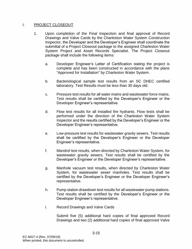
I. PROJECT CLOSEOUT
1. Upon completion of the Final Inspection and final approval of Record Drawings and Valve Cards by the Charleston Water System Construction Inspector, the Developer and the Developer’s Engineer shall coordinate the submittal of a Project Closeout package to the assigned Charleston Water System Project and Asset Records Specialist. The Project Closeout package shall include the following items: a. Developer Engineer’s Letter of Certification stating the project is
complete and has been constructed in accordance with the plans “Approved for Installation” by Charleston Water System.
b. Bacteriological sample test results from an SC DHEC certified laboratory. Test Results must be less than 30 days old.
c. Pressure test results for all water mains and wastewater force mains.
Test results shall be certified by the Developer’s Engineer or the Developer Engineer’s representative.
d. Flow test results for all installed fire hydrants. Flow tests shall be
performed under the direction of the Charleston Water System Inspector and the results certified by the Developer’s Engineer or the Developer Engineer’s representative.
e. Low-pressure test results for wastewater gravity sewers. Test results
shall be certified by the Developer’s Engineer or the Developer Engineer’s representative.
f. Mandrel test results, when directed by Charleston Water System, for wastewater gravity sewers. Test results shall be certified by the Developer’s Engineer or the Developer Engineer’s representative.
g. Manhole vacuum test results, when directed by Charleston Water System, for wastewater sewer manholes. Test results shall be certified by the Developer’s Engineer or the Developer Engineer’s representative.
h. Pump station drawdown test results for all wastewater pump stations. Test results shall be certified by the Developer’s Engineer or the Developer Engineer’s representative.
i. Record Drawings and Valve Cards
Submit five (5) additional hard copies of final approved Record Drawings and two (2) additional hard copies of final approved Valve

3-16 EC-MGT-4 (Rev. 07/09/18) When printed, this document is uncontrolled.
Cards along with required Digital Submittals as described below. The Developer’s Engineer or Surveyor shall deliver digital files on a CD or DVD in AutoCAD format (.dwg). Charleston Water System does not use Civil Packages inside AutoCAD; therefore, the State Plane Coordinates must be tied to the drawing in AutoCAD in order for the drawings to be placed in the correct position inside GIS. For more information, contact the GIS Technician at (843) 727-7128.
1. Record Drawings in AutoCAD format
a. Submit in accordance with the requirements of Part
H.1.a of this Section.
b. Provide in NAD 83 South Carolina State Plane Coordinates, oriented Grid North and tied to the current realization of the South Carolina Geodetic Survey Virtual Reference Station (VRS) network. Vertical coordinates shall be related to the National Geodetic Vertical Datum NGVD 1929 (Z coordinate). The Bench Mark and vertical datum shall be noted on the Developer’s plans. Example: THIS DRAWING REFERENCES NAD 83 (2011) HORIZONTAL STATE PLANE COORDINATE SYSTEM, ELEVATIONS ARE BASED ON NGVD 1929 VERTICAL DATUM.
c. Show each drawing entity with coordinates tied to SC
Grid, and show the grid tie at the point of connection to the existing system with bearing and distance to the Grid monument used and identified.
d. Have water and wastewater lines in separate drawing
layers.
e. Have all water appurtenances (i.e., hydrants, valves, services, tees, etc.) and all wastewater appurtenances (i.e., manholes, valves, cleanouts, etc.) in separate drawing layers.
2. Coordinate Table
A Coordinate Table with coordinate values (Northing, Easting) and elevations related to NGVD 1929 for all installed water and/or wastewater appurtenances shall be delivered in a comma delimited ASCII file in the format Point Number, Northing, Easting, Elevation and Description. Elevations must be provided for water valves (captured from top of nut, not the

3-17 EC-MGT-4 (Rev. 07/09/18) When printed, this document is uncontrolled.
lid) and wastewater manholes (captured rim elevation). If abbreviations are used as descriptors, a key to those abbreviations must be provided. Coordinate figures shall be based on the South Carolina State Plane Coordinate System, NAD 83 and ties to the current realization of the South Carolina Geodetic Survey Virtual Reference Station (VRS) network. The surveyor also has the option to provide this file as a .txt or .xls file with the same format as referenced above.
3. Valve Cards in AutoCAD format Submit in accordance with the requirements of Part H.1.b of this Section.
4. Record Drawings and Easement Plats (PDF)
a. PDF shall be black and white with white background.
Minimal color text or graphics pertinent to the submittal will be accepted.
b. Final PDF should be saved to open in proper orientation.
c. If drawing is multiple pages, either a single multi-page
PDF or individual files are allowed. If individual files are used, clearly show the page number within the drawing file name.
j. Asset Inventory Worksheet
The Asset Inventory Worksheet (submitted digitally in Excel format) shall include all assets removed or installed as reflected by the As Constructed condition and the corresponding Record Drawings. Items documented in the Asset Inventory Worksheet will be checked against the Record Drawing for accuracy. Any inaccuracies identified will require correction prior to worksheet acceptance. The applicable sheets shall be submitted based on installed assets. All costs input in the inventory shall reflect, in general, all expenses associated with bringing the asset into service. Unit costs for linear assets shall be entered as price per foot of material.
k. Legal Documents (Click here for a fillable PDF of each Legal
Document) 1. Affidavit of Title Water – Establishes the Developer (Grantor)
as the possessor of the title of the water utility infrastructure

3-18 EC-MGT-4 (Rev. 07/09/18) When printed, this document is uncontrolled.
assets to be transferred to Charleston Water System (Grantee).
2. Affidavit of Title Wastewater – Establishes the Developer (Grantor) as the possessor of the title of the wastewater utility infrastructure assets to be transferred to Charleston Water System (Grantee).
3. Bill of Sale Water – Conveys ownership of the water utility infrastructure to Charleston Water System.
4. Bill of Sale Wastewater - Conveys ownership of the
wastewater utility infrastructure to Charleston Water System.
5. Maintenance Agreement Water – Establishes a two-year maintenance period for repair of any deficiencies in the water utility infrastructure at the expense of the Developer.
6. Maintenance Agreement Wastewater – Establishes a two-year maintenance period for repair of any deficiencies in the wastewater utility infrastructure at the expense of the Developer.
7. Pump Stations – For projects involving wastewater pump
stations, the following additional legal documents shall be provided:
a. Affidavit for Transfer of Real Property - Establishes the
Grantor as the possessor of the title of the real property to be transferred to Charleston Water System (Grantee).
b. Title to Real Estate – Conveys ownership of the real property from the Grantor to Charleston Water System (Grantee).
c. Affidavit for Exempt Transfer – Establishes the deed as
being exempt from the deed recording fee because it is a transfer to a political subdivision of the State.
l. Easements
1. Plats - Submit six (6) hard copies; each must have original
signature and seal. The prints shall be no larger than 22” x 34”and prepared in accordance with the requirements of Charleston Water System and the requirements of the Office
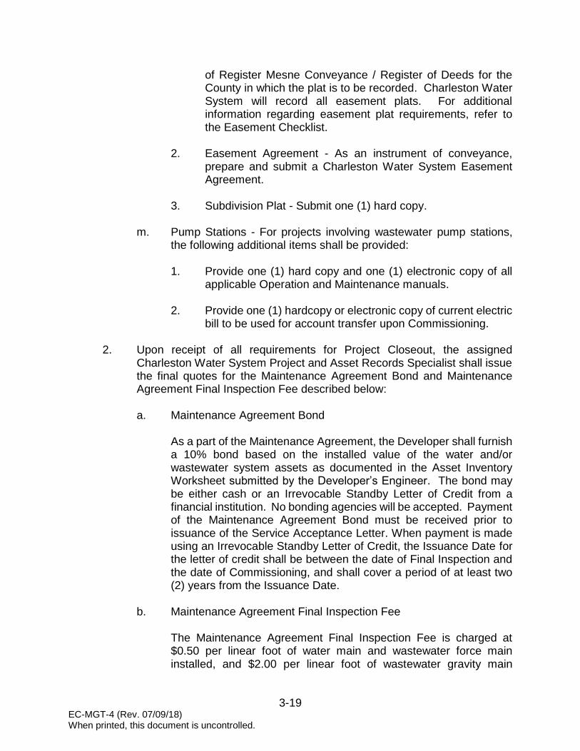
3-19 EC-MGT-4 (Rev. 07/09/18) When printed, this document is uncontrolled.
of Register Mesne Conveyance / Register of Deeds for the County in which the plat is to be recorded. Charleston Water System will record all easement plats. For additional information regarding easement plat requirements, refer to the Easement Checklist.
2. Easement Agreement - As an instrument of conveyance, prepare and submit a Charleston Water System Easement Agreement.
3. Subdivision Plat - Submit one (1) hard copy.
m. Pump Stations - For projects involving wastewater pump stations,
the following additional items shall be provided: 1. Provide one (1) hard copy and one (1) electronic copy of all
applicable Operation and Maintenance manuals.
2. Provide one (1) hardcopy or electronic copy of current electric bill to be used for account transfer upon Commissioning.
2. Upon receipt of all requirements for Project Closeout, the assigned
Charleston Water System Project and Asset Records Specialist shall issue the final quotes for the Maintenance Agreement Bond and Maintenance Agreement Final Inspection Fee described below: a. Maintenance Agreement Bond
As a part of the Maintenance Agreement, the Developer shall furnish a 10% bond based on the installed value of the water and/or wastewater system assets as documented in the Asset Inventory Worksheet submitted by the Developer’s Engineer. The bond may be either cash or an Irrevocable Standby Letter of Credit from a financial institution. No bonding agencies will be accepted. Payment of the Maintenance Agreement Bond must be received prior to issuance of the Service Acceptance Letter. When payment is made using an Irrevocable Standby Letter of Credit, the Issuance Date for the letter of credit shall be between the date of Final Inspection and the date of Commissioning, and shall cover a period of at least two (2) years from the Issuance Date.
b. Maintenance Agreement Final Inspection Fee
The Maintenance Agreement Final Inspection Fee is charged at $0.50 per linear foot of water main and wastewater force main installed, and $2.00 per linear foot of wastewater gravity main

3-20 EC-MGT-4 (Rev. 07/09/18) When printed, this document is uncontrolled.
installed. This is a non-refundable fee which covers expenses to perform the Maintenance Agreement final inspection. Payment of the Maintenance Agreement Final Inspection Fee must be received prior to issuance of the Service Acceptance Letter.
3. Concurrently, the Charleston Water System Project and Asset Records Specialist will issue an O&M letter to SC DHEC. This letter is in conjunction with any documentation from the Developer’s Engineer required by SC DHEC for issuance of a Permit to Operate.
J. COMMISSIONING
1. The purpose of the Commissioning is to ensure all punch list items have been satisfactorily addressed by the Contractor and to conduct a final walk through of the constructed water and/or wastewater systems. Upon acceptance of the systems by all parties, the Charleston Water System Construction Inspector shall have all responsible parties sign a Project Commissioning Form documenting final acceptance.
2. Upon receipt of the SC DHEC Permit to Operate, the Developer’s Engineer shall coordinate with the assigned Charleston Water System Construction Inspector to schedule the onsite Project Commissioning. A minimum of five (5) working days shall be allowed for scheduling. The Developer’s Engineer, Charleston Water System Approved Contractor and the assigned Charleston Water System Construction Inspector shall be in attendance.
3. The items listed below shall be provided by the Developer’s Engineer for use at the Commissioning. If any items are not provided, Commissioning will not proceed: a. Two (2) hard copies of final Record Drawings sealed, signed, and
dated by an Engineer registered in the state of South Carolina. These copies are in addition to those required in Part I of this Section.
b. Two (2) hard copies of all water main and wastewater force main
Valve Cards. These copies are in addition to those required in Part I of this Section.
4. Pump Stations
For projects involving wastewater pump stations, the following additional items shall be provided: a. Two (2) hard copies of final Pump Station Record Drawings sealed,
signed, and dated by an Engineer registered in the state of South Carolina. These copies are in addition to those required in Part I of this Section.

3-21 EC-MGT-4 (Rev. 07/09/18) When printed, this document is uncontrolled.
b. Complete set of spare parts as specified in Section 18 of these standards.
c. Operation and Maintenance Manuals
1. Four (4) hard copies and one (1) electronic PDF submittal of
operation, maintenance, and service manuals for each piece of equipment prepared in the following format: a. Manuals shall be specific to the equipment supplied
1. Provide factory pump curves for installed pumps
2. Manuals applicable to many different
configurations and which require the operator to selectively read portions of the instructions will not be accepted
3. The equipment model that the manual applies to
shall be indicated by an arrow
b. Table of Contents specific to each manual
c. At the beginning of each manual, provide a description of the equipment to include model numbers, purchase order numbers, serial numbers, motor information, and performance and design criteria
d. Correlate manuals with approved shop drawings and include the following minimum information:
1. Parts list, including recommended spare parts
2. Guarantees/Warranties
3. Provide a maintenance and lubrication schedule
to be a summary of all preventative maintenance and lubrication
4. Address and telephone numbers of the source for repairs, spare parts, and service
5. Detailed descriptions of operating procedures for the item of equipment specifically written for this installation, including start-up and shut-down procedures

3-22 EC-MGT-4 (Rev. 07/09/18) When printed, this document is uncontrolled.
6. Equipment performance specifications, including pump curves and drawdown test data
7. Results of start-up and any further recommendations resulting from start-up
d. Upon successful Commissioning, the assigned Charleston Water
System Project and Asset Records Specialist will transfer the pump station electrical service account to Charleston Water System.
K. APPLICATION FOR NEW SERVICES
1. Upon successful Project Commissioning and payment of all Project Closeout fees, a Service Acceptance Letter will be issued to Charleston Water System’s Customer Service Department. No request for services will be accepted prior to issuance of the Service Acceptance Letter.
2. Applications for service shall be submitted through Charleston Water
System’s Customer Service Department. Application may be made in person, at our website or by contacting the Customer Service Department at (843) 727-6800. Accurate account information is required to ensure correct billing and to expedite the installation of services. Tap fees are generally paid at this time.
3. If Charleston Water System has determined that a backflow prevention assembly is required, a notification will be mailed to the Owner. Water service will not be turned on until the assembly has been installed by the Owner’s contractor and inspected by Charleston Water System’s Cross-Connection Control Department. It is the responsibility of the contractor installing the assembly to notify the Cross-Connection Control Department and to schedule the inspection. Upon successful completion of the inspection, the assembly must be tested within seven (7) days after the date of inspection. Testing is the responsibility of the Owner and must be performed by a Charleston Water System Approved Backflow Prevention Assembly Tester. Information regarding Charleston Water System’s backflow prevention requirements is available on the New Development page of our website or by contacting the Cross Connection Control Program Manager at (843) 727-7216.
4. Any wastewater service connection to a Charleston Water System cleanout must be inspected by Charleston Water System’s Wastewater Collection Department prior to backfilling the wastewater service at the point of connection to the cleanout. To schedule an inspection, contact the Wastewater Collection Department by email at [email protected].
3-23 EC-MGT-4 (Rev. 07/09/18) When printed, this document is uncontrolled.
5. For wastewater services requiring a grease trap, a grease trap application must be submitted to Charleston Water System’s Wastewater Collection Department together with drawings/schematics for the proposed grease trap and plumbing connections. Grease trap applications must be approved prior to installation and a complete inspection of the installed grease trap must be performed by Charleston Water System prior to service acceptance. Additional information regarding Charleston Water System’s grease trap requirements is available on the Sewer Service page of our website or by contacting the Wastewater Collection System Engineering Manager at (843) 308-8277 or (843) 308-8299.
L. PROJECT CANCELLATION
1. Any project without “Activity” from the Developer, the Developer’s Engineer or the Developer’s Utility Contractor for a period of twelve (12) months, concerning intent to proceed with the project, shall be cancelled by Charleston Water System and any Service Availability Letter issued by Charleston Water System for utility service shall be considered withdrawn. Examples of “Activity” include such actions as plan submittals, payment of fees, meetings with Charleston Water System’s New Development Program Manager and/or Engineering & Construction Department Staff, written correspondence concerning design, submittal of permit applications, and water and/or wastewater construction activities. Examples not considered “Activity” are submittals to other municipal planning departments or review boards, telephone calls, and correspondence with other permitting agencies.
2. Impact Fee refunds will be handled according to the status of the project at the time it is canceled. Please see Section 5 of these standards for a complete description. If the Developer wishes to proceed with a project after Charleston Water System has closed its project file, a new project submittal will be required in conformance with Charleston Water System’s current policies. Impact Fees will be assessed at the rates current at the time the project is resubmitted.
3. Engineering Services Fee refunds will be handled according to the status
of the project at the time it is canceled. Please see Section 5 of these standards for a complete description. If the Developer wishes to proceed with a project after Charleston Water System has closed its project file, a new project submittal will be required in conformance with Charleston Water System’s current policies. Engineering Services Fees will be assessed at the rates current at the time the project is resubmitted. No credit will be given for Engineering Services Fees previously retained by Charleston Water System for projects that have been canceled and resubmitted.

CHECKLISTS

Charleston Water System Closeout Checklist – Water
PROJECT NAME:
ENGINEERING FIRM:
ENGINEERING CONTACT: DATE:
Page 1 of 1 AG-AM-6 (Rev. 06/02/17) When printed, this document is uncontrolled.
Required Items (refer to Minimum Standards)
Engineer Complete
CWS Complete Incomplete
Engineer’s Letter of Certification
Bacteriological sample test results
Pressure test results
Record drawing (5 hard copies)
Valve cards (2 hard copies)
Digital submittal (record drawings, valve cards, dummy valve cards, easement plat, coordinate table - ASCII file)
PDF submittal (record drawings, valve cards, dummy valve cards, easement plat)
Asset Inventory Worksheet
Affidavit of Title
Bill of Sale
Maintenance Agreement (if required)
Approved easement plat (6 hard copies)
Recorded subdivision plat (1 hard copy)
Easement Agreement
10% Maintenance Agreement Bond (if required)
Maintenance Agreement Final Inspection Fee (if required)
Signatures (sign and date)
ENGINEER: DATE:
CWS PARS: DATE:
CWS INSPECTOR: DATE:

Charleston Water System Closeout Checklist – Wastewater
PROJECT NAME:
ENGINEERING FIRM:
ENGINEERING CONTACT: DATE:
Page 1 of 1 AG-AM-7 (Rev. 08/01/17) When printed, this document is uncontrolled.
Required Items (refer to Minimum Standards)
Engineer Complete
CWS Complete Incomplete
Engineer’s Letter of Certification
Pressure test results (force mains)
Low-pressure test results (gravity sewer)
Mandrel test results (gravity sewer)
Manhole vacuum test results (gravity sewer)
Pump station drawdown test results
Record drawing (5 hard copies)
Valve cards (2 hard copies)
Digital submittal (record drawings, valve cards, dummy valve cards, easement plat, ASCII file)
PDF submittal (record drawings, valve cards, dummy valve cards, easement plat)
Asset Inventory Worksheet
Affidavit of Title
Bill of Sale
Maintenance Agreement (if required)
Affidavit for Transfer of Real Property (pump station)
Affidavit for Exempt Transfer of Real Property (pump station)
Title to Real Estate (pump station)
Approved easement plat (6 hard copies)
Recorded subdivision plat (1 hard copy)
Easement Agreement
Pump station operation and maintenance manuals (1 hard copy, 1 electronic)
Pump station electric bill for account transfer (hard copy or electronic)
10% Maintenance Agreement Bond (if required)
Maintenance Agreement Final Inspection Fee (if required)
Signatures (sign and date)
ENGINEER: DATE:
CWS PARS: DATE:
CWS INSPECTOR: DATE:

Charleston Water System Record Drawing Checklist – Water
PROJECT NAME: ENGINEERING FIRM: ENGINEERING CONTACT: DATE:
Page 1 of 2 AG-AM-8 (Rev. 07/09/18) When printed, this document is uncontrolled.
Required Items (refer to Minimum Standards)
Engineer Complete
CWS Complete Incomplete
CWS Project Name (on all sheets) CWS Project # (on all sheets) CWS Extension # (on all sheets) DHEC Permit # (on all sheets) Block Designation Tax Map Numbers Lot and Unit Numbers Street Names Site Map – Minimum size 3”x 3” Text Height – 0.08-inch or larger New mains must be shown as a dark, thick line and labeled with length, diameter, material (example: 150 LF, 6” DIP) Graphic and Relative Scales - Maximum 1”=40’ North Arrow Legend Utility Contractor’s Name, Address, Phone Number, Email Address Engineering Firm Name, Address, Phone Number Construction Completion Date (month, year) Horizontal (NAD 83) and Vertical Datum (NGVD 29) (on all sheets) Professional Land Surveyor (PLS) Signature & Stamp Registered Professional Engineer (PE) Signature & Stamp Water Easements – Label as “xx-FT CWS Utility Easement” Installed Material Listing – CWS Asset Inventory Worksheet and Record Drawing must reflect same information:
Pipe – length, diameter, material Valves – size, type, quantity Hydrants – make, quantity Services – diameter, quantity
Coordinate Table for all installed water appurtenances in a tabular format, State Plane Coordinates (NAD 83) to include:
Point Number Northing Easting Elevation

Charleston Water System Record Drawing Checklist – Water
PROJECT NAME: ENGINEERING FIRM: ENGINEERING CONTACT: DATE:
Page 2 of 2 AG-AM-8 (Rev. 07/09/18) When printed, this document is uncontrolled.
Required Items (refer to Minimum Standards)
Engineer Complete
CWS Complete Incomplete
Station Number Description
Profiles must be provided for: Mains 10” and larger Mains on Peninsula Charleston regardless of main size Mains at storm drain crossings
Indicate how the new main ties into the existing main (show as dashed and label size), show point of tie-in in State Plane Coordinates Indicate main diameter, material type, and total distance on line Service Lines – indicate distance from main to meter box (example: 20 LF, 1” Copper) End of Main – label and show in State Plane Coordinates
Signatures (sign and date)
ENGINEER: DATE:
CWS PARS: DATE:
CWS INSPECTOR: DATE:

Charleston Water System Record Drawing Checklist – Wastewater Gravity Sewer Only
PROJECT NAME: ENGINEERING FIRM: ENGINEERING CONTACT: DATE:
Page 1 of 2 AG-AM-9 (Rev. 07/09/18) When printed, this document is uncontrolled.
Required Items (refer to Minimum Standards)
Engineer Complete
CWS Complete Incomplete
CWS Project Name (on all sheets) CWS Project # (on all sheets) CWS Extension # (on all sheets) DHEC Permit # (on all sheets) Block Designation Tax Map Numbers Lot and Unit Numbers Street Names Site Map – minimum size 3”x 3” Text Height – 0.08-inch or larger New mains must be shown as a dark, thick line and labeled with length, diameter, material (example: 150 LF, 8” PVC) Graphic and Relative Scales - Maximum 1”=40’ North Arrow Legend Utility Contractor’s Name, Address, Phone Number, Email Address Engineering Firm Name, Address, Phone Number Construction Completion Date (month, year) Horizontal (NAD 83) and Vertical Datum (NGVD 29) (on all sheets) Professional Land Surveyor (PLS) Signature and Stamp Registered Professional Engineer (PE) Signature and Stamp Sewer Easements – Label as “xx-FT CWS Utility Easement” Installed Material Listing – CWS Asset Inventory Worksheet and Record Drawing must reflect same information:
Pipe – length, diameter, material Manholes – diameter, quantity Services – diameter, quantity Cleanouts – quantity
Coordinate Table for all installed sewer appurtenances in a tabular format, State Plane Coordinates (NAD 83) to include:
Point Number Northing Easting Elevation

Charleston Water System Record Drawing Checklist – Wastewater Gravity Sewer Only
PROJECT NAME: ENGINEERING FIRM: ENGINEERING CONTACT: DATE:
Page 2 of 2 AG-AM-9 (Rev. 07/09/18) When printed, this document is uncontrolled.
Required Items (refer to Minimum Standards)
Engineer Complete
CWS Complete Incomplete
Station Number Description
Indicate how the new main ties into the existing main (show as dashed and label size), show point of tie-in in State Plane Coordinates. Manhole Invert and Top Elevations - show on both Plan and Profile sheets Manhole Station Numbers – must be tied to State Plane Coordinates Manholes Numbered Gravity Sewer Mains (show on both Plan and Profile):
Length – manhole to manhole Percent of grade (slope) – manhole to manhole DIP Sewer Sections – manhole to manhole length or other sections
Wye Stations – Station number and must be tied to State Plane Coordinates Service Lines – indicate distance from main to first cleanout within the easement or right-of-way End of Main – label and show in State Plane Coordinates
Signatures (sign and date)
ENGINEER: DATE:
CWS PARS: DATE:
CWS INSPECTOR: DATE:
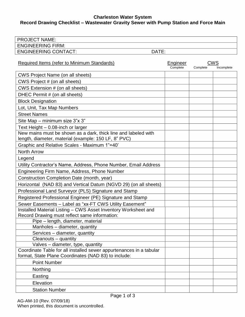
Charleston Water System Record Drawing Checklist – Wastewater Gravity Sewer with Pump Station and Force Main
PROJECT NAME: ENGINEERING FIRM: ENGINEERING CONTACT: DATE:
Page 1 of 3 AG-AM-10 (Rev. 07/09/18) When printed, this document is uncontrolled.
Required Items (refer to Minimum Standards)
Engineer Complete
CWS Complete Incomplete
CWS Project Name (on all sheets) CWS Project # (on all sheets) CWS Extension # (on all sheets) DHEC Permit # (on all sheets) Block Designation Lot, Unit, Tax Map Numbers Street Names Site Map – minimum size 3”x 3” Text Height – 0.08-inch or larger New mains must be shown as a dark, thick line and labeled with length, diameter, material (example: 150 LF, 8” PVC) Graphic and Relative Scales - Maximum 1”=40’ North Arrow Legend Utility Contractor’s Name, Address, Phone Number, Email Address Engineering Firm Name, Address, Phone Number Construction Completion Date (month, year) Horizontal (NAD 83) and Vertical Datum (NGVD 29) (on all sheets) Professional Land Surveyor (PLS) Signature and Stamp Registered Professional Engineer (PE) Signature and Stamp Sewer Easements – Label as “xx-FT CWS Utility Easement” Installed Material Listing – CWS Asset Inventory Worksheet and Record Drawing must reflect same information:
Pipe – length, diameter, material Manholes – diameter, quantity Services – diameter, quantity Cleanouts – quantity Valves – diameter, type, quantity
Coordinate Table for all installed sewer appurtenances in a tabular format, State Plane Coordinates (NAD 83) to include:
Point Number Northing Easting Elevation Station Number

Charleston Water System Record Drawing Checklist – Wastewater Gravity Sewer with Pump Station and Force Main
PROJECT NAME: ENGINEERING FIRM: ENGINEERING CONTACT: DATE:
Page 2 of 3 AG-AM-10 (Rev. 07/09/18) When printed, this document is uncontrolled.
Description Required Items (refer to Minimum Standards)
Engineer Complete
CWS Complete Incomplete
GRAVITY MAIN Indicate how the new gravity main ties into the existing main (show as dashed and label size), show point of tie-in in State Plane Coordinates Manhole Invert and Top Elevations - show on both Plan and Profile sheets Manhole Station Numbers – must be tied to State Plane Coordinates Manholes Numbered Gravity Sewer Mains (show on both Plan and Profile):
Length (manhole to manhole), diameter, material Percent of grade (slope) – manhole to manhole DIP Sewer Sections – manhole to manhole length or other sections
Wye Stations – Station number and must be tied to State Plane Coordinates Service Lines – indicate distance from main to first cleanout within the easement or right-of-way End of Main – label and show in State Plane Coordinates FORCE MAIN Engineer
Complete CWS
Complete Incomplete Indicate how the new force main ties into the existing force main or manhole (show as dashed and label size), show point of tie-in in State Plane Coordinates Sewer Force Mains (show on both Plan and Profile):
Length (pump station to discharge point), diameter, material Percent of Grade (slope) – if applicable Valves
Air Release Valve Station Numbers – must be tied to State Plane Coordinates Force Main Valves – must be in State Plane Coordinates with Stations Numbers (include elevation to top of operating nut)

Charleston Water System Record Drawing Checklist – Wastewater Gravity Sewer with Pump Station and Force Main
PROJECT NAME: ENGINEERING FIRM: ENGINEERING CONTACT: DATE:
Page 3 of 3 AG-AM-10 (Rev. 07/09/18) When printed, this document is uncontrolled.
Required Items (refer to Minimum Standards)
Engineer Complete
CWS Complete Incomplete
PUMP STATION Address and TMS# of Pump Station property (if known) Pump Station Plan and Details Pump Station Electrical Schematics
Signatures (sign and date)
ENGINEER: DATE:
CWS PARS: DATE:
CWS INSPECTOR: DATE:

Charleston Water System Valve Card Checklist - Water
PROJECT NAME:
ENGINEERING FIRM:
ENGINEERING CONTACT: DATE:
Page 1 of 2 AG-AM-11 (Rev. 06/02/17) When printed, this document is uncontrolled.
Required Items (refer to Minimum Standards)
Engineer Compete
CWS Complete Incomplete
CWS Project Name
CWS Project #
CWS Extension #
Two (2) tie-down dimensions to all mains, bends, fittings, valves, hydrants, meters, etc. from centerline of street pavement, sewer manholes, storm drain box, power poles (include power pole number), etc. (perpendicular dimensions only in whole feet, no tenths)
Tie-down dimension to the centerline of nearest recognized street or intersection
Street Names
Size and material of water mains and fittings
Concrete and asphalt pavements (sidewalks, driveways, streets, etc.)
Easements and width (if applicable)
Existing Utilities (if shown on Record Drawing)
Private valves shown as open circles and labeled as "Private Valve" (example: PIV for unmetered fire services, do not list in the valve table)
North Arrow
Existing Valve Card number when applicable
Valve table information:
Location
Size
Make (manufacturer/model)
Type (gate, butterfly, tapping, control)
Date set
Number of turns - counted on site
Opening (open left – OL, open right – OR)
Hydrant information:
Manufacturer/model – 3 way
Year
Bury depth (depth is determined by probing to top of pipe and adding 6”)
Opening size and direction (open left – OL, open right – OR)

Charleston Water System Valve Card Checklist - Water
PROJECT NAME:
ENGINEERING FIRM:
ENGINEERING CONTACT: DATE:
Page 2 of 2 AG-AM-11 (Rev. 06/02/17) When printed, this document is uncontrolled.
Required Items (refer to Minimum Standards)
Engineer Compete
CWS Complete Incomplete
Extension kit installed (include length of extension)
NOTE: for reference use CWS detail drawing #28 "Typical Water Valve Card" located in the Standard Construction Detail Drawings of the Minimum Standards
Signatures (sign and date)
ENGINEER: DATE:
CWS PARS: DATE:
CWS INSPECTOR: DATE:
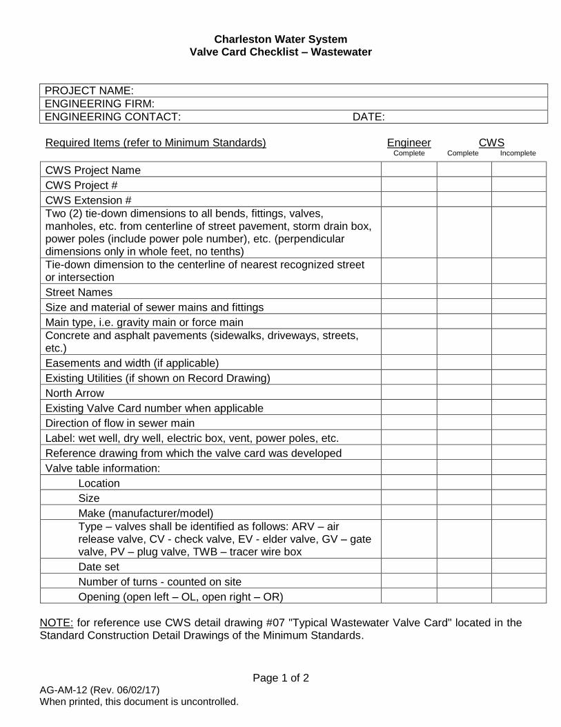
Charleston Water System Valve Card Checklist – Wastewater
PROJECT NAME:
ENGINEERING FIRM:
ENGINEERING CONTACT: DATE:
Page 1 of 2 AG-AM-12 (Rev. 06/02/17) When printed, this document is uncontrolled.
Required Items (refer to Minimum Standards)
Engineer Complete
CWS Complete Incomplete
CWS Project Name
CWS Project #
CWS Extension #
Two (2) tie-down dimensions to all bends, fittings, valves, manholes, etc. from centerline of street pavement, storm drain box, power poles (include power pole number), etc. (perpendicular dimensions only in whole feet, no tenths)
Tie-down dimension to the centerline of nearest recognized street or intersection
Street Names
Size and material of sewer mains and fittings
Main type, i.e. gravity main or force main
Concrete and asphalt pavements (sidewalks, driveways, streets, etc.)
Easements and width (if applicable)
Existing Utilities (if shown on Record Drawing)
North Arrow
Existing Valve Card number when applicable
Direction of flow in sewer main
Label: wet well, dry well, electric box, vent, power poles, etc.
Reference drawing from which the valve card was developed
Valve table information:
Location
Size
Make (manufacturer/model)
Type – valves shall be identified as follows: ARV – air release valve, CV - check valve, EV - elder valve, GV – gate valve, PV – plug valve, TWB – tracer wire box
Date set
Number of turns - counted on site
Opening (open left – OL, open right – OR)
NOTE: for reference use CWS detail drawing #07 "Typical Wastewater Valve Card" located in the Standard Construction Detail Drawings of the Minimum Standards.

Charleston Water System Valve Card Checklist – Wastewater
PROJECT NAME:
ENGINEERING FIRM:
ENGINEERING CONTACT: DATE:
Page 2 of 2 AG-AM-12 (Rev. 06/02/17) When printed, this document is uncontrolled.
Signatures (sign and date)
ENGINEER: DATE:
CWS PARS: DATE:
CWS INSPECTOR: DATE:

Charleston Water System Easement Plat Checklist
PROJECT NAME:
ENGINEERING FIRM:
ENGINEERING CONTACT: DATE:
Page 1 of 2 AG-AM-13 (Rev. 06/02/17) When printed, this document is uncontrolled.
Required Items (refer to Minimum Standards)
Engineer
CWS Complete Not Complete
CWS Project Name (on all sheets)
CWS Project # (on all sheets)
CWS Extension # (on all sheets)
Minimum size – 11" x17"
Maximum size - 22" x 34"
Prints stamped and sealed with surveyor’s impression seal
Prints signed by a Registered Land Surveyor, original signatures on all copies
Location description of property
City, county and state where lot is located
Date of survey or plat
Graphic and Relative Scales - Maximum 1”=50’
North Arrow
Legend
Surveyors’ Name, Address, Phone Number, Email Address
Registration number of Surveyor & certification relative to class
Name of subdivision of which survey is a part
Book and page number of the subdivision as registered in the R.M.C. office of the County where plat is recorded, if applicable
North arrow designated using State Plane Coordinate System
Must have one State Plane Coordinate Tie
Bearing and distance plotted to the scale indicated on the plat
Name of adjacent land owners or lot numbers
Highway and/or street(s) name
Waterways
List all prior plat/deed references
Does the title read "PLAT OF A (STATE WIDTH) UTILITY EASEMENT PREPARED FOR THE CHARLESTON CPW THROUGH THE PROPERTY(IES) OF (STATE OWNERS NAME)”
Do all easement sidelines have bearings and distances?
Are tie distances from the sidelines of the easement to the property corners of all properties crossed, including all individual subdivision lot lines?
Is the total width of the easement shown?

Charleston Water System Easement Plat Checklist
PROJECT NAME:
ENGINEERING FIRM:
ENGINEERING CONTACT: DATE:
Page 2 of 2 AG-AM-13 (Rev. 06/02/17) When printed, this document is uncontrolled.
Required Items (refer to Minimum Standards)
Engineer
CWS Complete Not Complete
Does easement curve data include delta, radius, length, chord, and chord bearing?
Is the Tax Map Number shown on the plat?
Are all existing easements shown?
Have encroachment permits been obtained for all existing easements, which are being encroached upon?
Have ALL CURRENT South Carolina LLR minimum standards been met?
Have six (6) prints, with original signatures been sent to Charleston Water System?
Signatures (sign and date)
ENGINEER: DATE:
CWS PARS: DATE:
CWS SURVEY MANAGER: DATE:

LEGAL DOCUMENTS

Page 1 of 1
STATE OF SOUTH CAROLINA ) ) BILL OF SALE
COUNTY OF _______________ ) WATER
KNOW ALL MEN BY THESE PRESENTS, that __________________________________ for and in consideration of the sum of ONE AND NO/100 Dollars ($1.00), and other valuable consideration, to it in hand paid, at and before the sealing and delivery of these presents by THE COMMISSIONERS OF PUBLIC WORKS OF THE CITY OF CHARLESTON, the receipt of which is hereby acknowledged, have bargained and sold, and by these presents do bargain, sell, and deliver to the said THE COMMISSIONERS OF PUBLIC WORKS OF THE CITY OF CHARLESTON, the following described property, to-wit:
Pipes, manholes, pump stations, valves, fittings and all appurtenances associated with the water utility infrastructure installed at Seller’s expense within those areas designated within the pump station site, dedicated easements or located within the rights-of-way of any street on that certain plat entitled ________________________________________________________________________ dated ___________________, prepared by ________________________________, P.L.S. and all other water utility infrastructure components installed subsequent to the date of said plat, through this date.
To have and to hold the same unto the said THE COMMISSIONERS OF PUBLIC WORKS OF THE CITY OF CHARLESTON, its Successors and Assigns, forever.
And the Seller does hereby bind its Heirs, Successors and Assigns, to warrant and forever defend all and singular the said bargained property unto the said THE COMMISSIONERS OF PUBLIC WORKS OF THE CITY OF CHARLESTON, its Successors and Assigns, against Grantor and its Heirs, Successors and Assigns, and all persons lawfully claiming or to claim the same, or any part thereof.
IN WITNESS WHEREOF Grantor has hereunto set its hand and seal on the _____ day of _______________, 20 ____.
_____________________________ _____________________________ Signature of Witness Signature of Grantor
_____________________________ _____________________________ Signature of Witness Type or Print Name of Grantor
Sworn to before me this ________day of ________________________, 20_____.
____________________________________________ (Notary Affix Seal) Notary Public for the State of _____________________ My Commission Expires: ________________________
AG-AM-15 (Rev. 06/02/17)When printed, this document is uncontrolled.

Page 1 of 1
STATE OF SOUTH CAROLINA ) ) BILL OF SALE
COUNTY OF _______________ ) WASTEWATER
KNOW ALL MEN BY THESE PRESENTS, that __________________________________ for and in consideration of the sum of ONE AND NO/100 Dollars ($1.00), and other valuable consideration, to it in hand paid, at and before the sealing and delivery of these presents by THE COMMISSIONERS OF PUBLIC WORKS OF THE CITY OF CHARLESTON, the receipt of which is hereby acknowledged, have bargained and sold, and by these presents do bargain, sell, and deliver to the said THE COMMISSIONERS OF PUBLIC WORKS OF THE CITY OF CHARLESTON, the following described property, to-wit:
Pipes, manholes, pump stations, valves, fittings and all appurtenances associated with the wastewater utility infrastructure installed at Seller’s expense within those areas designated within the pump station site, dedicated easements or located within the rights-of-way of any street on that certain plat entitled ___________________________________________________________ dated _______________________, prepared by ______________________________, P.L.S. and all other wastewater utility infrastructure components installed subsequent to the date of said plat, through this date.
To have and to hold the same unto the said THE COMMISSIONERS OF PUBLIC WORKS OF THE CITY OF CHARLESTON, its Successors and Assigns, forever.
And the Seller does hereby bind its Heirs, Successors and Assigns, to warrant and forever defend all and singular the said bargained property unto the said THE COMMISSIONERS OF PUBLIC WORKS OF THE CITY OF CHARLESTON, its Successors and Assigns, against Grantor and its Heirs, Successors and Assigns, and all persons lawfully claiming or to claim the same, or any part thereof.
IN WITNESS WHEREOF Grantor has hereunto set its hand and seal on the _____ day of _______________, 20 ____.
_____________________________ _____________________________ Signature of Witness Signature of Grantor
_____________________________ _____________________________ Signature of Witness Type or Print Name of Grantor
Sworn to before me this ________day of ________________________, 20_____.
____________________________________________ (Notary Affix Seal) Notary Public for the State of _____________________ My Commission Expires: ________________________
AG-AM-16 (Rev. 06/02/17)When printed, this document is uncontrolled.

Page 1 of 1
AG-AM-17 (Rev. 06/02/17)When printed, this document is uncontrolled.
STATE OF SOUTH CAROLINA ) ) AFFIDAVIT OF TITLE COUNTY OF _______________ ) WATER
______________________________________________________________________, being duly sworn, deposes and says:
1. That ____________________________________________________________________,a duly organized corporation under the laws of the State of _________________________,is the sole owner of the water utility infrastructure described in the Bill of Sale to which thisAffidavit is attached and that is the same entity which executed the Bill of Sale to which thisAffidavit is attached.
2. That said business has full right to transfer title to the above described water utilityinfrastructure.
3. That such water utility infrastructure is free and clear of all liens, security interest, liabilities,obligations and encumbrances.
4. That there are no judgments against ___________________________________________in any court of the State of South Carolina or the United States and there are no replevins,attachment executions, or other writs against said business; that it has not filed any petitionin bankruptcy, nor has any petition in bankruptcy been filed against said business; and that ithas not been adjudicated a bankrupt.
IN WITNESS WHEREOF Grantor has hereunto set its hand and seal on the _____ day of_______________, 20 ____.
_____________________________ _____________________________ Signature of Witness Signature of Grantor
_____________________________ _____________________________ Signature of Witness Type or Print Name of Grantor
Sworn to before me this ________day of ________________________, 20_____.
____________________________________________ (Notary Affix Seal) Notary Public for the State of _____________________ My Commission Expires: ________________________

Page 1 of 1
AG-AM-18 (Rev. 06/02/17)When printed, this document is uncontrolled.
STATE OF SOUTH CAROLINA ) ) AFFIDAVIT OF TITLE COUNTY OF _______________ ) WASTEWATER
______________________________________________________________________, being duly sworn, deposes and says:
1. That ____________________________________________________________________,a duly organized corporation under the laws of the State of _________________________,is the sole owner of the wastewater utility infrastructure described in the Bill of Sale to whichthis Affidavit is attached and that is the same entity which executed the Bill of Sale to whichthis Affidavit is attached.
2. That said business has full right to transfer title to the above described wastewater utilityinfrastructure.
3. That such wastewater utility infrastructure is free and clear of all liens, security interest,liabilities, obligations and encumbrances.
4. That there are no judgments against ___________________________________________in any court of the State of South Carolina or the United States and there are no replevins,attachment executions, or other writs against said business; that it has not filed any petitionin bankruptcy, nor has any petition in bankruptcy been filed against said business; and that ithas not been adjudicated a bankrupt.
IN WITNESS WHEREOF Grantor has hereunto set its hand and seal on the _____ day of_______________, 20 ____.
_____________________________ _____________________________ Signature of Witness Signature of Grantor
_____________________________ _____________________________ Signature of Witness Type or Print Name of Grantor
Sworn to before me this ________day of ________________________, 20_____.
____________________________________________ (Notary Affix Seal) Notary Public for the State of _____________________ My Commission Expires: ________________________

Page 1 of 1 AG-AM-19 (Rev. 06/02/17)When printed, this document is uncontrolled.
STATE OF SOUTH CAROLINA ) ) AFFIDAVIT FOR
COUNTY OF _______________ ) TRANSFER OF REAL PROPERTY
PERSONALLY appeared before me the undersigned, who being duly sworn, deposes and says:
1. I have read the information on this Affidavit and I understand such information.
2. The property is being transferred by Title to Real Estate to The Commissioners of Public Works of the City of
Charleston on this ________day of ________________________, 20____.
3. Check one of the following: The DEED is
a. _________ subject to the deed recording fee as a transfer for consideration paid or to be paid in money or
money’s worth.
b. _________ subject to the deed recording fee as a transfer between a corporation, a partnership, or other entity
and a stockholder partner or owner of the entity or is a transfer to a trust or as distribution to a trust beneficiary.
c. EXEMPT from the deed recording fee because of exemption #2.
(If exempt, please skip items 4-6, and go to item 8 on this affidavit.)
4. Check one of the following if either item 3(a) or item 3(b) above has been checked.
a. _________The fee computed on the consideration paid or to be paid in money or money’s worth in the amount
of $__________.
b. _________The fee is computed on the fair market value of the realty.
c. _________The fee is computed on the fair market value of the realty as established for property tax purposes
which is $_________.
5. Check YES___ or NO___ to the following: A lien of encumbrance existed on the land, tenement, or realty before the
transfer and remained on the land, tenement, or reality after the transfer. If “YES”, the amount of the outstanding
balance of this lien or encumbrance is $______________________.
6. The DEED Recording Fee is computed as follows:
a. $ _______The amount listed in item 4 above.
b. $ _______The amount listed in item 5 above (no amount place zero).
c. $ _______Subtract Line 6(b) from Line 6(a) and place the result.
7. As required by Code Section 12-24-70, I state that I am the responsible person who was connected with the
transaction as Grantor, Grantee or Legal Representative.
8. I understand that a person required to furnish this affidavit who willfully furnishes a false or fraudulent affidavit is
guilty of a misdemeanor and, upon conviction, must be fined not more than one thousand dollars or imprisoned not
more than one year, or both.
Sworn to before me this ________day of ___________________________________________
Grantor, Grantee or Legal Representative
___________________________, 20_____ Connected with this transaction (sign above)
___________________________________________
(Type or Print Name Here)
_________________________________________ (Notary Affix Seal) Notary Public for the State of __________________
My Commission Expires: _____________________

Page 1 of 2
AG-AM-20 (Rev. 06/02/17)When printed, this document is uncontrolled.
STATE OF SOUTH CAROLINA ) ) TITLE TO REAL ESTATE COUNTY OF _______________ )
KNOW ALL MEN BY THESE PRESENTS, that ____________________________________ in the State aforesaid, in consideration of the sum of ONE AND NO/100 DOLLARS ($1.00), to the Grantor(s) in hand paid at and before sealing of the presents by the Grantee(s) (the receipt whereof is hereby acknowledged), have granted, bargained, sold and released, and by these presents do grant, bargain, sell and release unto the said THE COMMISSIONERS OF PUBLIC WORKS OF THE CITY OF CHARLESTON:
ALL that lot, piece or tract of land in County of ____________________ and State aforesaid, as shown on that certain plat entitled “________________________________________________” dated _______________________, prepared by ____________________________, P.L.S., and recorded in the RMC/ROD Office for _____________________ County in Plat Book ________, Page ______, and more fully delineated as follows: _____________________________________________________________________________ .
BEING A PORTION OF THE SAME PROPERTY conveyed to ________________________ by Deed of __________________________________ dated ____________________, and recorded in the RMC/ROD Office for _______________County on ____________________, in Book _______, Page______.
TMS No. _________________________
GRANTEE(S) ADDRESS: 103 St. Philip Street, Charleston, South Carolina 29403
TOGETHER with all and Singular the Rights, Members, Hereditaments and Appurtenances to the said premises belonging, or in anywise incident or appertaining.
TO HAVE AND TO HOLD and all singular the said Premises before mentioned unto the Grantee(s) hereinabove named, and Grantee’s(s) Successors and Assigns, forever.
And the Grantor(s) do(es) hereby bind the Grantor(s) and the Grantor’s Heirs, Successors and Assigns, to warrant and forever defend all and singular the said premises unto the Grantee(s) here in above named, and the Grantee’s Successors and Assigns against the Grantor(s) and the Grantor’s Heirs, Successors, and Assigns against every person whomsoever lawfully claiming or to claim the same or any part thereof.

Page 2 of 2 Rev. 05/01/17
Witness the Grantor’s hand(s) and seal(s) this ______ day of _______________, 20______. Signed, Sealed and Delivered in the Presence of: _____________________________ _____________________________ Signature of Witness Signature of Grantor _____________________________ _____________________________ Signature of Witness Type or Print Name of Grantor STATE OF SOUTH CAROLINA )
) ACKNOWLEDGEMENT COUNTY OF _______________ ) I, ___________________________, Notary Public for the State of _______________________, do
hereby certify that ___________________________________________ personally appeared
before me this day and acknowledged the due execution of the foregoing instrument.
Sworn to before me this _____ day of _______________, 20 ____. _____________________________________________________ Notary Affix Seal
Notary Public for the State of _____________________________ My Commission Expires: ________________________________

Page 1 of 1
AG-AM-21 (Rev. 06/02/17)When printed, this document is uncontrolled.
STATE OF SOUTH CAROLINA ) ) AFFIDAVIT FOR COUNTY OF _______________ ) EXEMPT TRANSFER
PERSONALLY appeared before me the undersigned, who being duly sworn, deposes and says:
1. I have read the information on this affidavit and I understand such information.
2. The property being transferred is located at __________________________________________bearing County Tax Map Number ___________________, was transferred by easementdocument to The Commissioners of Public Works of the City of Charleston (CPW) on the____day of ___________, 20______.
3. The deed is exempt from the deed recording free because it is a transfer to a political subdivisionof the State.
If exempt under exemption #14 as described in the Information section of this affidavit, did the agent and principal relationship exist at the time of the original sale and was the purpose of this relationship to purchase the realty? Check Yes ___ or No X
4. As required by Code Section 12-24-70, I state that I am a responsible person who was connectedwith the transaction as: Officer of The Commissioners of Public Works of the City of Charleston(Grantee).
5. I understand that a person required to furnish this affidavit who willfully furnishes a false orfraudulent affidavit is guilty of a misdemeanor and, upon conviction, must be fined not more thanone thousand dollars or imprisoned not more than one year, or both.
_________________________________________ Responsible Person Connected with the Transaction
_________________________________________ Type or Print Name Here
Sworn to before me this ________day of ________________________, 20_____.
____________________________________________ (Notary Affix Seal)
Notary Public for the State of _____________________ My Commission Expires: ________________________

Page 1 of 1
AG-AM-22 (Rev. 06/02/17)When printed, this document is uncontrolled.
STATE OF SOUTH CAROLINA ) ) MAINTENANCE AGREEMENT
COUNTY OF _______________ ) WATER
We, the undersigned ____________________________________________________, as Developer(s) of ____________________________________________________________ agree to guarantee on behalf of The Commissioners of Public Works of The City of Charleston (The Commission) that any deficiencies found within the said development’s water utility infrastructure will be repaired at the Developer’s expense for the period of two (2) years from the date of Commissioning of the water utility infrastructure for said project, which occurred on the ______day of ________________, 20 ______.
Now, therefore, the condition of this obligation is such that the Developer shall make good all defects appearing in the work performed installing the water utility infrastructure for said project. Defects shall be defined as faulty workmanship or materials which may develop during the period of two (2) years from the date of Commissioning of the water utility infrastructure. Should the above conditions be met, this agreement shall be null and void and the total amount of the maintenance bond returned to:
Name: _________________________________________ Company to receive refund
Address: _________________________________________ Street Address (P.O. Box Not Accepted)
_________________________________________ City, State & Zip Code
The Commission shall notify the Developer of defective work requiring immediate repair. If the defective work is not corrected within thirty (30) days of the Developer’s receipt of this notification, The Commission has the right to make the repairs by whatever means necessary and use the Developer’s 10% maintenance bond in the amount of $ ______________________ to pay all costs for said repairs. Additionally, The Commission may also hold or cancel the installation of future services within the development.
IN WITNESS WHEREOF Grantor has hereunto set its hand and seal on the _____ day of _______________, 20 ____.
_____________________________ _______________________________ Signature of Witness Signature of Grantor
_____________________________ _______________________________ Signature of Witness Type or Print Name of Grantor
Sworn to before me this _____ day of _______________, 20 ____.
_____________________________________________________ Notary Affix Seal Notary Public for the State of _____________________________ My Commission Expires: ________________________________

Page 1 of 1
AG-AM-23 (Rev. 06/02/17)When printed, this document is uncontrolled.
STATE OF SOUTH CAROLINA ) ) MAINTENANCE AGREEMENT
COUNTY OF _______________ ) WASTEWATER
We, the undersigned ____________________________________________________, as Developer(s) of ____________________________________________________________ agree to guarantee on behalf of The Commissioners of Public Works of The City of Charleston (The Commission) that any deficiencies found within the said development’s wastewater utility infrastructure will be repaired at the Developer’s expense for the period of two (2) years from the date of Commissioning of the wastewater utility infrastructure for said project, which occurred on the ______day of ________________, 20 ______.
Now, therefore, the condition of this obligation is such that the Developer shall make good all defects appearing in the work performed installing the wastewater utility infrastructure for said project. Defects shall be defined as faulty workmanship or materials which may develop during the period of two (2) years from the date of Commissioning of the wastewater utility infrastructure. Should the above conditions be met, this agreement shall be null and void and the total amount of the maintenance bond returned to:
Name: _________________________________________ Company to receive refund
Address: _________________________________________ Street Address (P.O. Box Not Accepted)
_________________________________________ City, State & Zip Code
The Commission shall notify the Developer of defective work requiring immediate repair. If the defective work is not corrected within thirty (30) days of the Developer’s receipt of this notification, The Commission has the right to make the repairs by whatever means necessary and use the Developer’s 10% maintenance bond in the amount of $ ______________________ to pay all costs for said repairs. Additionally, The Commission may also hold or cancel the installation of future services within the development.
IN WITNESS WHEREOF Grantor has hereunto set its hand and seal on the _____ day of _______________, 20 ____.
_____________________________ _______________________________ Signature of Witness Signature of Grantor
_____________________________ _______________________________ Signature of Witness Type or Print Name of Grantor
Sworn to before me this _____ day of _______________, 20 ____.
_____________________________________________________ Notary Affix Seal Notary Public for the State of _____________________________ My Commission Expires: ________________________________

FINANCIAL DOCUMENTS

NOTE: FORM MAY VARY, SUBSTANCE MAY NOT AG-AM-24 (Rev. 08/01/17) When printed, this document is uncontrolled.
SAMPLE - IRREVOCABLE STANDBY LETTER OF CREDIT
(NOTE: FORM MAY VARY, SUBSTANCE MAY NOT)
BANK LETTERHEAD
IRREVOCABLE STANDBY LETTER OF CREDIT
TO: ENGINEERING & CONSTRUCTION DEPARTMENT COMMISSIONERS OF PUBLIC WORKS 103 ST PHILIP STREET CHARLESTON, SC 29403 EFFECTIVE DATE AMOUNT OF LETTER OF CREDIT $ DEVELOPER CWS PROJECT NUMBER CWS PROJECT NAME LETTER OF CREDIT NUMBER
To Whom It May Concern: We hereby establish our “Irrevocable Standby Letter of Credit” in your favor, available by your draft(s) at sight, drawn on (Name of Bank issuing this Standby letter of Credit) accompanied by a manually signed statement that the signer is “an authorized Officer or representative of the Commissioners of Public Works of the City of Charleston, South Carolina (Commissioners). Each Draft shall include the following documentation:
a) A copy of the original Letter of Credit, together with any amendments, and b) A sight draft drawn by Charleston Water System
Drafts must be presented for negotiations at our bank on or before the expiration date of this letter, (Expiration Date), which shall be not less than Two (2) Years from the Effective Date of this letter. This Letter of Credit shall be governed by the International Chamber of Commerce (ICC) Uniform Customs and Practice for Documentary Credits, 2007 Revision UCP 600 or most current revision in force on the date of issuance. This Letter of Credit shall also be governed by the laws of the State of South Carolina. In the event of any conflict, the laws of the State of South Carolina will control. We hereby agree with the drawers, endorsers and bona fide holders that all drafts drawn under and in compliance with the terms of this Letter of Credit will be duly honored upon presentation of the above documents for negotiation at our bank on or before the expiration date. If Charleston Water System has not drawn the full amount of this Letter of Credit prior to the Expiration Date, the Expiration Date shall be automatically extended for a period of sixty (60) days from the Expiration Date, unless the Issuer notifies Charleston Water System in writing at least sixty (60) days prior to the Expiration Date that the issuer elects not to extend this Letter of Credit. If the Issuer elects not to extend this Letter of Credit, any unused amount of the credit shall be available to Charleston Water System upon presentation of the required draft documentation prior to the Expiration Date. Very truly yours, ____________________________________________ (Authorized Signature) ____________________________________________ (Typed Name and Title)

EASEMENT AGREEMENT

Page 1 of 7 AG-AM-25 (Rev. 06/02/17) When printed, this document is uncontrolled.
STATE OF SOUTH CAROLINA ) ) RIGHT- OF-WAY COUNTY OF _______________ ) AND UTILITY EASEMENT
WHEREAS, the undersigned own(s) a certain parcel of land bearing
_______________ County Tax Map number ___________________; and
WHEREAS, the Commissioners of Public Works of the City of Charleston,
South Carolina has requested a permanent easement across said property for the
purpose of constructing utility lines which the property owner(s) has/have agreed to
grant.
NOW, THEREFORE, KNOW ALL MEN BY THESE PRESENTS, that Legal
Name of Property Owner(s) (hereinafter called the "Grantor(s)"), in consideration
of the sum of __________________________ and 00/100 ($_______________.00)
Dollars to the Grantor(s) in hand paid for the easements granted hereunder, at and
before the sealing of these presents, by the COMMISSIONERS OF PUBLIC
WORKS OF THE CITY OF CHARLESTON, SOUTH CAROLINA, the receipt of
which is hereby acknowledged, has/have granted, bargained, sold and released, and
by these presents does/do grant, bargain, sell and release unto the
COMMISSIONERS OF PUBLIC WORKS OF THE CITY OF CHARLESTON,
SOUTH CAROLINA (hereinafter called the "Commissioners"), its successors and
assigns forever, the following right-of-way(s) and easement(s):
A permanent, transferable, assignable right–of–way and utility easement for
a commercial purpose over, under and across a strip of land designated “XX
PERMANENT EASEMENT X.XX ACRE/XX.XX SQ. FT” and shown as being
contained between the lines running between the letters designated A, B, C etc. on

Page 2 of 7 AG-AM-25 (Rev. 06/02/17) When printed, this document is uncontrolled.
a plat entitled “Name of Plat” by NAME OF LICENSED LAND SURVEYOR P.L.S.
No. XXXX of Name of Company dated Month, Day Year and last revised Month,
Day Year and recorded in Plat Book _______ at page __________ in the RMC Office
or the Office of Register of Deeds for County Name County, South Carolina. Said
strip of land has such size, shape, dimensions, buttings and boundings, courses and
distances as will by reference to said plat more fully appear. The permanent right-
of-way and utility easement is hereinafter referred to as “Permanent Easement.”
Together with the right by the Commissioners to lay, construct, locate, install,
operate, maintain, inspect, repair, relocate and replace underground water lines and
underground sewer lines with necessary valves, valve boxes, meters, fittings,
manholes, service lines, controls, devices, equipment, fire hydrants and other usual
appurtenances within the Permanent Easement.
TOGETHER with all the rights and privileges necessary or convenient for the
full enjoyment or use thereof.
It is further agreed that:
(1) The Commissioners will have the right of ingress, egress, and
access to and from the Permanent Easement across and upon
such lands of the Grantor(s) as may be necessary or convenient
for purposes connected with said Permanent Easement.
(2) The Commissioners shall have the right from time to time to
trim, cut or remove trees, underbrush and other obstructions
that are over, under or upon the Permanent Easement.

Page 3 of 7 AG-AM-25 (Rev. 06/02/17) When printed, this document is uncontrolled.
(3) The Grantor(s) and his/her/its/their heirs, successors and
assigns, will have full use of the surface area of the Permanent
Easement, provided, however, that neither Grantor(s) nor
his/her/its/or their heirs, successors or assigns shall construct,
build or place any permanent structure, or portion thereof,
within, above, below or over the surface of the Permanent
Easement, it being the purpose of the Commissioners to (1)
protect the integrity of the said utility lines which will be located
below the surface, and (2) to allow quick and ready access to
the utility lines to facilitate repairs.
(4) Commissioners agrees that upon completion of construction,
the surface of any unpaved portions of the Permanent
Easement which are highland that are disturbed by construction
or maintenance, will be regraded and replanted with grass. Any
pavement damaged by construction or maintenance will be
repaired. The surface of any unpaved portions of the
Permanent Easement which are wetlands or marsh that are
disturbed by construction or maintenance, if any, will be
restored in accordance with the permits issued by the authority
or authorities having jurisdiction over said wetlands or marsh.
(5) The Permanent Easement will run with the land and continue to
exist so long as it is used for utility purposes. In the event the
Commissioners should determine to abandon its rights in the

Page 4 of 7 AG-AM-25 (Rev. 06/02/17) When printed, this document is uncontrolled.
Permanent Easement, written notice will be given to the then
owners of the property subject to the Permanent Easement
stating that the Commissioners has given up all rights in the
Permanent Easement.
(6) The Permanent Easement granted herein is for a commercial
purpose and may be transferred and assigned by
Commissioners and its successors and assigns.
(7) The agreements contained herein shall be binding upon the
Commissioners and Grantor (s) and their respective heirs,
successors and assigns.
TO HAVE AND TO HOLD, all and singular, the easements rights and
privileges above described unto the COMMISSIONERS OF PUBLIC WORKS OF
THE CITY OF CHARLESTON and its successors and assigns forever.
IN WITNESS WHEREOF, the undersigned have set their hands and seals
this ____ day of ____________ 2____________.
WITNESSES: COMMISSIONERS OF PUBLIC WORKS OF THE CITY OF CHARLESTON, SOUTH CAROLINA ___________________________ By: __________________________ Its: ___________________________ ___________________________

Page 5 of 7 AG-AM-25 (Rev. 06/02/17) When printed, this document is uncontrolled.
SIGNATURE BLOCK AND ACKNOWLEDGMENT FOR INDIVIDUAL GRANTORS WITNESSES: _________________________ ______________________________ Name of Grantor ________________________ STATE OF __________________ ) ) ACKNOWLEDGEMENT COUNTY OF ________________ ) I, ______________________________, Notary Public for the State of
_______________________, do hereby certify that _________________________
personally appeared before me this day and acknowledged the due execution of the
foregoing instrument.
Subscribed to and sworn before me this ______ day of _________________,
2_______.
______________________________________
Notary Public, State of ____________________
My commission expires: ___________________

Page 6 of 7 AG-AM-25 (Rev. 06/02/17) When printed, this document is uncontrolled.
SIGNATURE BLOCK AND ACKNOWLEDGMENT FOR CORPORATE GRANTOR
WITNESSES: ______________________________ Name of Corporate Grantor _________________________ By: __________________________ Authorized Signer Its: __________________________ ______________________ ___ STATE OF __________________ ) ) ACKNOWLEDGEMENT COUNTY OF ________________ ) I, ______________________________, Notary Public for the State of
_______________________, do hereby certify that _________________________
by _________________________ its ___________________________ personally
appeared before me this day and acknowledged the due execution of the foregoing
instrument.
Subscribed to and sworn before me this ______ day of _________________,
2_______.
______________________________________
Notary Public, State of ____________________
My commission expires: ___________________

Page 7 of 7 AG-AM-25 (Rev. 06/02/17) When printed, this document is uncontrolled.
STATE OF SOUTH CAROLINA ) ) ACKNOWLEDGMENT COUNTY OF CHARLESTON ) I, __________________________________, Notary Public for the State of South Carolina, do hereby certify that the Commissioners of Public Works of the City of Charleston, South Carolina by _____________________________ its _____________________________, personally appeared before me this day and acknowledged the due execution of the foregoing instrument. Subscribed to and sworn before me this ______ day of _______________, 2________. ______________________________________ Notary Public, State of South Carolina My commission expires: __________________

4-1 EC-MGT-5 (Rev. 06/02/17) When printed, this document is uncontrolled.
SECTION 4
EASEMENTS The following information covers easement requirements and is applicable to all developments requiring water and/or wastewater service from Charleston Water System. No deviation to these requirements will be allowed without the expressed written consent of Charleston Water System. A. GENERAL INFORMATION
1. Easements for all water and wastewater mains shall be conveyed to
Charleston Water System in the name of the Commissioners of Public Works of the City of Charleston, SC using Charleston Water System’s standard Easement Agreement document.
2. Easements shall be platted so as to provide equal distance on each side of the installed water or wastewater main within the easement.
3. Easements shall be clear of trees and debris, and grassed unless other
treatment is specifically approved by Charleston Water System.
4. Obstructions within, above or below any easement such as buildings, building footers, building overhangs, canopy-type trees, overhead structures or other objects or structures which may limit access to or use of the entire easement by Charleston Water System are not permitted.
5. For additional information and requirements concerning easements, contact
Charleston Water System’s Survey Manager at (843) 727-6859. B. EASEMENT WIDTH
1. Water Mains
a. Width of easement shall not be less than fifteen (15) feet.
b. Water mains installed within the easement shall be platted so as to
provide equal distance on each side.
c. Edge of easement should not be less than five (5) feet from any building, building footer or permanent structure.
2. Wastewater Gravity Mains
a. Width of easement shall not be less than twenty (20) feet.
b. Wastewater mains installed within the easement shall be platted so

4-2 EC-MGT-5 (Rev. 06/02/17) When printed, this document is uncontrolled.
as to provide equal distance on each side.
c. Edge of easement should not be less than five (5) feet from any building, building footer or permanent structure.
3. Wastewater Force Mains
a. Width of easement shall not be less than fifteen (15) feet.
b. Wastewater mains installed within the easement shall be platted so
as to provide equal distance on each side.
c. Edge of easement should not be less than five (5) feet from any building, building footer or permanent structure.
4. Water and Wastewater Mains
a. When water and wastewater mains are placed in the same
easement, mains shall be laid to provide a minimum ten (10) foot horizontal separation between inside edges of pipe. The width of the easement shall be increased to provide a distance not less than ten (10) feet from the edge of the easement to the centerline of each main.
b. When water and wastewater mains are owned by different utilities, each main shall be placed in a separate easement and shall be laid in a manner so as to provide the minimum separation requirements for water and wastewater mains as set forth in these standards. The easements may overlap, but shall not include any portion of the main belonging to the other utility.
c. In all cases, edge of Charleston Water System easement should not be less than five (5) feet from any building, building footer or permanent structure.
5. Wastewater Gravity Mains and Force Mains
a. When wastewater gravity mains and force mains are placed in the
same easement, mains shall be laid to provide a minimum ten (10) foot horizontal separation between inside edges of pipe. The width of the easement shall be increased to provide a distance not less than ten (10) feet from the edge of the easement to the centerline of each main.
b. Edge of easement should not be less than five (5) feet from any building, building footer or permanent structure.

4-3 EC-MGT-5 (Rev. 06/02/17) When printed, this document is uncontrolled.
c. Charleston Water System reserves the right to increase the width of any easement when conditions are determined by Charleston Water System to require said increase.
C. EASEMENT PLAT
1. Prepare and submit easement plats in accordance with Section 3,
paragraph I.1.k.1 of these standards.
2. For additional information regarding easement plat requirements, refer to the Easement Checklist.
D. EASEMENT AGREEMENT
As an instrument of conveyance, prepare and submit a Charleston Water System standard Easement Agreement document in accordance with Section 3, paragraph I.1.k.2 of these standards.

5-1 EC-MGT-6 (Rev. 06/02/17) When printed, this document is uncontrolled.
SECTION 5
DEVELOPMENT FEES The following information is a general description of Charleston Water System’s Development Fees and is applicable to all developments requiring water and/or wastewater service from Charleston Water System. The fees listed may not be all inclusive and other Charleston Water System fees may apply. A. GENERAL INFORMATION
1. The Developer shall be responsible for payment of all applicable development fees.
2. Development fees are available on the New Development page of our
website. Charleston Water System’s development fees are subject to review by its Board of Commissioners and may be amended from time to time. Projects will be subject to the most current fees in affect at the time full payment is received.
3. Prior to designing water and/or wastewater systems, the Developer and the Developer’s Engineer are encouraged to take into careful consideration all Charleston Water System development policies. Development policies are available on the New Development page of our website.
4. For additional information concerning development policies and fees,
contact Charleston Water System’s New Development Program Manager at (843) 727-6869.
B. TAP AND IMPACT FEES
1. Water
a. Tap Fees – At the time of application for water service, a water Tap Fee shall be assessed to the customer for each meter based on its size, the purpose of which is to recover costs to Charleston Water System of inspection and installing the meter and associated appurtenances.
b. Impact Fees – The purpose of water Impact Fees is to assist
Charleston Water System in paying the cost associated with expansion of major components of the water distribution system. These fees will normally be charged to and paid by a Developer at the time of execution of a Charleston Water System contract for extension of a water system and prior to beginning construction of said water system. The total charge for water Impact Fees will be

5-2 EC-MGT-6 (Rev. 06/02/17) When printed, this document is uncontrolled.
based upon the total number of meters (and their sizes) anticipated to be installed. Individual customers will also be required to pay the same Impact Fees for water services (other than new residential irrigation services and dedicated fire services) connecting to Charleston Water System mains. No portion of the total Impact Fee assessment is refundable after Project Commissioning or after individual service installations.
c. Impact Fees are inclusive of $500 Engineering Services Fee.
d. No Tap or Impact Fee will be charged for dedicated, unmetered fire
services.
2. Wastewater
a. Tap Fees – At the time of application for wastewater service, a Tap Fee shall be assessed to the customer for each tap based on its size, the purpose of which is to recover costs to Charleston Water System for installing the initial service lateral and inspecting the tie-in of the customer’s service line to the Charleston Water System service lateral.
b. Impact Fees – The purpose of wastewater Impact Fees is to assist
Charleston Water System in paying the cost associated with expansion of major components of the wastewater system. These fees will normally be charged to and paid by a Developer at the time of execution of a Charleston Water System contract for extension of a wastewater system and prior to beginning construction of said wastewater system. The total charge for wastewater Impact Fees will be based upon the number of equivalent residential units in the proposed development at the Impact Fee rate per equivalent unit. No portion of the total Impact Fee assessment is refundable after Project Commissioning or after individual service installation.
1. Residential Development – Wastewater Impact Fees for
residential development are based on standard South Carolina Department of Health and Environmental Control (SC DHEC) contributory loading for single family residential services.
2. Commercial Development – Wastewater Impact Fees for
commercial development differs from residential development. For information on the determination of wastewater Impact Fees for commercial developments, contact Charleston Water System’s New Development Program Manager at (843) 727-6869.
5-3 EC-MGT-6 (Rev. 06/02/17) When printed, this document is uncontrolled.
c. Impact Fees are inclusive of $500 Engineering Services Fee.
C. ENGINEERING SERVICES FEE DEPOSIT Charleston Water System will charge an Engineering Services Fee of five hundred
dollars ($500) as a component of each Impact Fee assessed. The Engineering Services Fee will serve to fund the cost of reviewing Developer and Customer plans, specifications, design documents, sketches, calculations, and providing other associated administrative services and construction inspection services associated with new development and the installation of new services. One hundred dollars ($100) of each of the Engineering Services Fee assessed shall be considered a non-refundable Engineering Services Fee Deposit collected at the time plans are submitted for review to cover Charleston Water System engineering and administrative costs. In no case will the total Engineering Services Fee Deposit amount be less than $500 for a single project submittal with less than five assessable services. The deposit will be credited toward the total Engineering Services Fee amount due for the project once final plans are approved for permitting. Prior to permitting, Charleston Water System will collect the balance of the Engineering Services Fee due with the total Impact Fees due.
D. MAINTENANCE AGREEMENT BOND
The Maintenance Agreement includes a 10% bond based on the installed value of the water and/or wastewater system assets as documented in the Asset Inventory Worksheet submitted by the Developer’s Engineer at project closeout. The bond may be either cash or an Irrevocable Standby Letter of Credit from a financial institution. No bonding agencies will be accepted. The bond will be held for a period not to exceed two (2) years from the date of Commissioning and will be refunded upon completion of the Maintenance Agreement Final Inspection, provided no deficiencies are found. If deficiencies are found and the Developer does not correct these deficiencies, the bond will be used to cover costs to make corrections. In which case, the entire bond amount will then be forfeited. Payment of the Maintenance Agreement Bond must be received prior to issuance of the Service Acceptance Letter.
E. MAINTENANCE AGREEMENT FINAL INSPECTION FEE
Prior to releasing the Maintenance Bond, Charleston Water System will perform a final inspection of the installed water and/or wastewater system assets. For the purpose of making said inspections, a Maintenance Agreement Final Inspection Fee is charged. The Maintenance Agreement Final Inspection Fee will be based on the installed linear footage of water and/or wastewater mains as documented in the Asset Inventory Worksheet submitted by the Developer’s Engineer at project closeout. The Maintenance Agreement Final Inspection Fee will be charged at $.50 per linear foot of water main and wastewater force main, and $2.00 per linear foot of wastewater gravity main. Payment of the Maintenance Agreement Final

5-4 EC-MGT-6 (Rev. 06/02/17) When printed, this document is uncontrolled.
Inspection Fee must be received prior to issuance of the Service Acceptance Letter.
F. ORIGINATION FEE The Origination Fee is a fee charged to partially off-set the administrative and customer service costs required to establish a new account and to render a final bill when the account is closed.
G. IMPACT FEE REIMBURSEMENT
No portion of the total Impact Fee assessment is refundable after Project Commissioning or after individual service installation.
H. ENGINEERING SERVICES FEE REIMBURSEMENT
Engineering Services Fees paid to Charleston Water System may be reimbursed to the Developer, less the Engineering Services Fee Deposit amount, if the project is cancelled or the scope of the project is reduced prior to Project Commissioning. No credit will be given for any portion of Engineering Services Fees previously retained by Charleston Water System if the project is reinitiated at some later date.
I. OTHER FEES
Charleston Water System’s Water Distribution and Wastewater Collection Departments may charge inspection and oversight fees for projects involving services “only”, fire hydrants “only”, and unmetered fire services. For information on the determination of these fees, contact Charleston Water System’s New Development Program Manager at (843) 727-6869.

6-1 EC-MGT-7 (Rev. 07/09/18) When printed, this document is uncontrolled.
SECTION 6
WATER DISTRIBUTION SYSTEM DESIGN STANDARDS
The following information covers water distribution system design standards and is applicable to all developments requiring water service from Charleston Water System. No deviation from these standards will be allowed without the expressed written consent of Charleston Water System. A. GENERAL
1. The following water system design standards are based on Federal, State
and local health requirements and the requirements of Charleston Water System
2. These design standards are applicable to all development requiring water service from Charleston Water System
3. As a general rule, Charleston Water System does not allow aerial water
main crossings. Examples of aerial crossings include, but are not limited to, water mains constructed on piers or pilings, and water mains attached to structures such as roadways, bridges or piers.
4. Where it is necessary for water mains to cross surface water or wetlands, the preferred method of installation is by Horizontal Directional Drill or Jack and Bore. In either case, the Developer’s Engineer is encouraged to meet with Charleston Water System’s Engineering & Construction Department to discuss method of installation prior to submitting development plans for plan review. An appointment can be made by contacting Charleston Water System’s New Development Program Manager at (843) 727-6869.
B. DESIGN CRITERIA
1. Design water mains in accordance with the requirements of the South
Carolina Department of Health and Environmental Control State Primary Drinking Water Regulation R.61-58 and the requirements of these standards
2. Plan and Profile
a. Provide plan view for all water mains drawn to a horizontal scale no smaller than 1-inch equals 50-feet
b. When required, provide water main profile drawn to a vertical scale no smaller than 1-inch equals 5-feet

6-2 EC-MGT-7 (Rev. 07/09/18) When printed, this document is uncontrolled.
c. Provide plan and profile for all water mains 10-inch and larger
d. Provide plan and profile for all water mains to be constructed on peninsula Charleston, regardless of main size. Peninsula Charleston shall be defined as areas south of Mount Pleasant Street.
e. Provide plan and profile at each location where water main crosses
over or under a storm drainage pipe or structure
f. Provide plan and profile for all water mains installed by jack and bore or horizontal directional drill, regardless of main size
3. Water mains shall not be closer than 25-feet horizontally from any portion
of a wastewater tile field or spray field. If this separation is not possible, the water mains shall be protected by an acceptable method approved by SC DHEC and Charleston Water System.
4. Water mains shall be located outside of contaminated areas. Where it is necessary for water mains to cross contaminated areas, the Developer’s Engineer shall submit proposed method of construction to Charleston Water System’s Engineering & Construction Department for review and approval prior to submitting development plans for plan review. An appointment can be made by contacting Charleston Water System’s New Development Program Manager at (843) 727-6869.
5. There shall be no connection between the water distribution system and
any pipes, pumps, hydrants, or tanks whereby unsafe water or other contaminated materials may be discharged or drawn into the system
6. Locate water mains, valves and meters outside of paved roadway, if
possible. Do not locate water mains, valves, meters or hydrants under or behind parking spaces or in any other areas that could inhibit access for operations and maintenance.
7. Minimize dead-ends by looping of all water mains. Arrange water mains so
they are looped and interconnected at intersections without using crosses.
8. Where dead-ends occur, provide a fire hydrant on water mains 6-inch and larger and a blow off on water mains less than 6-inch. Charleston Water System does not permit installation of post hydrants for the purpose of flushing. Size flushing devices to provide flows with a velocity of at least 2.5 fps in the water main being flushed. See Construction Details
9. Provide an alternate source water main when an alternate source of water
supply is available within 500-feet
6-3 EC-MGT-7 (Rev. 07/09/18) When printed, this document is uncontrolled.
10. All water mains installed by direct bury or jack and bore shall be ductile iron pipe
11. All water mains installed by horizontal directional drill shall be High Density
Polyethylene (HDPE)
12. All buried ductile iron water mains, fittings and appurtenances shall be wrapped in V-Bio polyethylene encasement
13. Provide restrained joint pipe and fittings on all piping at each fitting, valve,
and fire hydrant connection. The location and length of restrained joint pipe will be clearly marked on the plans.
14. Provide minimum 36-inch to maximum 48-inch cover at finished grade. Justification and any deviation must be acceptable to Charleston Water System.
15. Water Main Size
a. Minimum water main size shall be 6-inch. 4-inch mains may be allowed on dead-end lines provided the main cannot be extended and the main does not provide fire protection. Justification and deviation must be acceptable to Charleston Water System.
b. Maximum water main size shall be no larger than the water main from which it is being extended from or, in the case of a looped water main, no larger than the water main to which it is being extended to, whichever being the larger.
c. Charleston Water System reserves the right to stipulate the
maximum water main size for any water main extension. C. CAPACITY DESIGN
1. Size mains based on either 1/5 the maximum instantaneous demand plus fire flow or maximum instantaneous demand, whichever is greater. The minimum pressure under conditions of maximum instantaneous demand shall be 25 psi at every service tap. 20 psi will be acceptable at any service tap when fire flows or flushing flows are provided in excess of maximum peak hourly flow.
2. Minimum design fire flow shall be 1000 gpm. A fire flow less than 1000 gpm may be accepted provided written approval is submitted to Charleston Water System from the jurisdictional authority for fire protection in the project area authorizing a fire flow less than 1000 gpm. Under no circumstance shall minimum design fire flow be less than 500 gpm.

6-4 EC-MGT-7 (Rev. 07/09/18) When printed, this document is uncontrolled.
3. Hydraulic calculations shall be based on the available static and residual pressure in the main to be extended.
4. Use Hazen and Williams design coefficient, C=120. When extending water mains on Peninsula Charleston, the design coefficient may be considerably less due to water main age and condition. For additional information regarding water mains on Peninsula Charleston, contact Charleston Water System’s New Development Program Manager at (843) 727-6869.
5. The maximum instantaneous demand is to be calculated using the tables provided below, as published in the Community Water System Source Book by Joseph S. Ameen.

6-5 EC-MGT-7 (Rev. 07/09/18) When printed, this document is uncontrolled.
Table XXI - Maximum Instantaneous Flows for Residential Areas
Number of Residences Served Flow per Residence in GPM
1 (First)
15.0
2 - 10*
5.0
11 - 20**
4.0
21 - 30
3.8
31 - 40
3.4
41 - 50
3.2
51 - 60
2.7
61 - 70
2.5
71 - 80
2.2
81 - 90
2.1
91 - 100
2.0
101 - 125
1.8
126 - 150
1.6
151 - 175
1.4
176 - 200
1.3
201 - 300
1.2
301 - 400
1.0
401 - 500
0.8
501 - 750
0.7
751 - 1,000
0.5
*Second, third, etc., through tenth residence served. **Eleventh, twelfth, etc., through twentieth residence served.

6-6 EC-MGT-7 (Rev. 07/09/18) When printed, this document is uncontrolled.
Table XXII - Maximum Instantaneous Flows for Commercial Areas
Type of Business GPM on Basis Shown
Barber Shop
3.0 gpm per chair
Beauty Shop
3.0 gpm per chair
Dentist Office
4.0 gpm per chair
Department Store*
1.0 - 2.0 - 3.0 gpm per employee
Drug Store
5.0 gpm
With Fountain Service
add 6.0 gpm per fountain area
Serving Meals
add 2.0 gpm per seat
Industrial Plants**
4.0 gpm plus 1.0 gpm per employee
Laundry
30.0 gpm per 1,000 pounds clothes
Launderette
8.0 gpm per unit
Meat Market, Super Market
6.0 gpm per 2,500 sq. ft. floor area
Motel, Hotel
4.0 gpm per unit
Office Building
0.5 gpm per 100 sq. ft. floor area or 2.0 gpm per employee
Physicians’ Office
3.0 gpm per examining room
Restaurant
2.0 gpm per seat
Single Service
6.0 to 20.0 gpm total
Drive-In
2.0 to 7.0 gpm total
Service Station
10.0 gpm per wash rack
Theater
0.2 gpm per seat
Drive-In
0.2 gpm per car space
Other Establishments***
Estimate at 4.0 gpm each
*Including customer service. **Not including process water. ***Non-water using establishments.

6-7 EC-MGT-7 (Rev. 07/09/18) When printed, this document is uncontrolled.
Table XXIII - Maximum Instantaneous Flows for Institutions
Type of Institution Basis of Flow, GPM
Boarding Schools, Colleges 2.0 gpm per student
Churches 0.4 gpm per member
Clubs: Country, Civic 0.6 gpm per member
Hospitals 4.0 gpm per bed
Nursing Homes 2.0 gpm per bed
Prisons 3.0 gpm per inmate
Rooming House Same as Residential*
Schools: Day, Elementary, Junior, Senior High
Number of Students GPM Per Student
0 –50 2.00
100 1.90
200 1.88
300 1.80
400 1.72
500 1.64
600 1.56
700 1.44
800 1.38
900 1.32
1,000 1.20
1,200 1.04
1,400 0.86
1,600 0.70
1,800 0.54
2,000 0.40
*Each unit of an apartment building should be considered as an individual residence.

6-8 EC-MGT-7 (Rev. 07/09/18) When printed, this document is uncontrolled.
D. RELATION TO SEWER MAINS 1. There shall be no physical connection between a public or private potable
water supply system and a sewer, or appurtenance thereto which may permit the passage of any sewage or polluted water into the potable supply. No potable water pipe shall pass through or come into contact with any part of a gravity sewer manhole.
2. Horizontal and Vertical Separation Water mains shall be laid at least 10-feet horizontally from any existing or proposed sewer main. The distance shall be measured edge to edge. For water mains where it is not practical to maintain 10-foot separation, deviation may be allowed provided that the water main is in a separate trench or on an undisturbed earth shelf located on one side of the sewer main and at an elevation so the bottom of the water main is at least 18-inches above the top of the sewer main. Justification and any deviation must be acceptable to Charleston Water System.
3. Crossings a. Water mains crossing sewer mains shall be laid to provide a
minimum vertical distance of 18-inches between the outside of the water main and the outside of the sewer main. This shall be the case whether the water main is either above or below the sewer main. Whenever possible, the water main shall be located above the sewer main. The crossing shall be arranged so that the water main joints will be equidistant and as far as possible from the sewer main joints. Where a water main crosses under a gravity sewer main, adequate structural support shall be provided for the gravity sewer main to maintain line and grade.
b. Where it is not practical to obtain proper horizontal and vertical separation as stipulated above, either the water main or the gravity sewer main shall be installed in a watertight steel casing that extends 10-feet either side of the crossing, measured perpendicular to the outside of the water main.
E. RELATION TO STORM DRAINS
1. General
No water main shall pass through or come into contact with any part of a storm drain pipe or structure.

6-9 EC-MGT-7 (Rev. 07/09/18) When printed, this document is uncontrolled.
2. Horizontal Separation Water mains shall be laid at least 5-feet horizontally from any existing or proposed storm drain pipe or structure. The distance shall be measured edge to edge.
3. Crossings Above Water mains crossing above storm drains shall be laid to provide a minimum vertical separation of 12-inches between the outside of the storm drain and the outside of the water main.
4. Crossings Below a. Single Barrel, 24-inch Diameter or Less
1. Water mains crossing below a single barrel storm drain pipe
24-inch diameter or less shall be laid to provide a minimum vertical separation of 18-inches between the outside of the storm drain and the outside of the water main.
2. Where vertical separation is between 18-inches and 42-inches, one full length of ductile iron water main shall be centered under the storm drain crossing. The crossing shall be arranged so that the water main joints will be equidistant and as far away as possible from the storm drain crossing.
b. Single Barrel, 30-inch Diameter or Greater
Water mains crossing below a single barrel storm drain pipe 30-inch diameter or greater shall be laid to provide a minimum vertical separation of 18-inches between the outside of the storm drain and the outside of the water main and shall be installed in a steel casing, regardless of the depth of vertical separation, that extends 5-feet on both sides of the crossing, measured perpendicular to the outside of the storm drain. A longer length may be required, as determined by Charleston Water System, based on the depth and location of the crossing. The crossing shall be arranged so that the water main joints will be equidistant and as far as possible from the storm drain crossing. See Construction Details
c. Multiple Barrel
Water mains crossing below two or more adjacent storm drain pipes, regardless of diameter, shall be laid to provide a minimum vertical separation of 18-inches between the outside of the storm drain and

6-10 EC-MGT-7 (Rev. 07/09/18) When printed, this document is uncontrolled.
the outside of the water main and shall be installed in a steel casing, regardless of the depth of vertical separation, that extends 5-feet on both sides of the crossing, measured perpendicular to the outside of the storm drain. A longer length may be required, as determined by Charleston Water System, based on the depth and location of the crossing. The crossing shall be arranged so that the water main joints will be equidistant and as far as possible from the storm drain crossing. See Construction Details
d. Box Culverts Water mains crossing below box culverts shall be laid to provide a minimum vertical separation of 18-inches between the outside of the box culvert and the outside of the water main and shall be installed in a steel casing, regardless of the depth of vertical separation, that extends 5-feet on both sides of the crossing, measured perpendicular to the outside of the box culvert. A longer length may be required, as determined by Charleston Water System, based on the depth or location of the crossing. The crossing shall be arranged so that the water main joints will be equidistant and as far as possible from the storm drain crossing. See Construction Details
F. SERVICES
1. Location
a. All meter boxes and meter vaults to be installed within road right-of-way, outside of the paved roadway, or in a Charleston Water System easement.
b. Install all service lines, meter boxes and meter vaults perpendicular to the road right-of-way or property line.
c. Locate ¾-inch and 1-inch services and meter box for residential
properties at the approximate midpoint of the front property line.
d. Locate meter box or meter vault either completely inside or completely outside of paved sidewalks. No portion of a meter box or meter vault shall be inside an ADA sidewalk ramp.
e. Do not locate meter box or meter vault in driveways, under or behind
parking spaces, or in any other areas that could inhibit access for operations and maintenance.
f. Maximum length of service line, from the water main to the meter,
shall not exceed 150-feet.
6-11 EC-MGT-7 (Rev. 07/09/18) When printed, this document is uncontrolled.
2. Tap Size a. General
1. Service taps, regardless of size, will not be permitted on water mains that are High Density Polyethylene (HDPE).
2. Service taps less than 6-inch will not be permitted on water mains that are greater than 16-inch.
3. Service taps less than 6-inch will not be permitted on water
mains that are Pre-stressed Concrete Cylinder Pipe (PCCP).
4. The service line, including any branch lines, from the tap to the customer’s point of connection, may be the same size as the tap, but may not be any larger.
5. Charleston Water System reserves the right to stipulate the
minimum or maximum size service tap available off of any water main regardless of the water main size.
b. Services, 2-inch and Smaller – Tap size shall be, at a minimum, one
size smaller than the water main being tapped.
c. Services, 3-inch and Larger – Tap size may be the same size as the water main being tapped, but may not be any larger.
d. Residential Fire Sprinkler Systems (One- and Two-Family Dwellings
and Manufactured Homes)
1. Charleston Water System Where it is necessary for water mains to cross contaminated areas, the Developer’s Engineer shall submit proposed method of construction to Charleston Water System’s Engineering & Construction Department for review and approval prior to submitting development plans for plan review. An appointment can be made by contacting Charleston Water System’s New Development Program Manager at (843) 727-6869.
2. All services for residential fire sprinkler systems not meeting the requirements of a Passive Purge or Multipurpose fire sprinkler system as defined by NFPA 13D shall be separated from the public potable water system by the appropriate backflow prevention device in accordance with Charleston Water System’s Cross Connection Control Program requirements.

6-12 EC-MGT-7 (Rev. 07/09/18) When printed, this document is uncontrolled.
G. JOINT RESTRAINT 1. General
a. Design restrained joints in accordance with the Ductile Iron Pipe
Research Association (DIPRA) standards for all fittings, valves, hydrants and pipe joints as required to resist forces during testing and normal operating pressures within the distribution system.
b. Retainer glands shall be used on all mechanical joint fittings. All tees, plugs, caps, and bends equal to or exceeding 11-1/4 degrees, and at other locations where unbalanced forces exist, must have acceptable thrust restraint. See Construction Details
2. Blocking
Provide thrust blocking only at wet taps, or as directed by Charleston Water System. The concrete mix shall have a 28-day compressive strength of not less than 3,000 psi. The bearing surface shall be as shown or as directed by Charleston Water System. Place the block so that the pipe and fitting joints will be accessible to repairs. See Construction Details
H. VALVES
1. Gate Valves and Butterfly Valves
a. Water mains 4-inch through 12-inch: Use resilient wedge gate valves
b. Water mains 16-inch and larger: User butterfly valves unless
specified otherwise
c. Provide valves at maximum 500-foot intervals. Requests for spacing greater than 500-foot will be reviewed on a case-by-case basis.
d. Provide three (3) valves for a tee intersection and four (4) valves for two-offset tee intersections. The use of crosses is not acceptable. See Construction Details
e. Valves should be placed to minimize the number of Charleston Water System customers out of service due to a water main break and/or any maintenance operation
f. Charleston Water System reserves the right to require additional valves if it is deemed in the best interest of current and future Charleston Water System customers
6-13 EC-MGT-7 (Rev. 07/09/18) When printed, this document is uncontrolled.
2. Air Release Valves a. Provide at high points in the water main
b. Design water main to minimize the number of air release valves
c. Provide at maximum 3,000-foot intervals where water main is
installed at little or no slope
d. Air release valves shall be sized based on the size of the water main
e. Automatic air release valves shall not be used in situations where flooding of the manhole or chamber may occur.
I. FIRE HYDRANTS
1. General
a. Minimum main size for water mains serving fire hydrants shall be 6-
inch.
b. Minimum size for hydrant lead shall be 6-inch.
c. Provide hydrant control valve on all hydrant leads.
d. As a matter of policy, Charleston Water System does not allow the installation of private hydrants. Exceptions to this policy may be made on a case-by-as basis, subject to the approval of the Chief Executive Officer.
2. Design Flow
a. Minimum flow for all fire hydrants shall be 1,000 gpm. A flow less
than 1,000 gpm may be accepted provided written approval is submitted to Charleston Water System from the jurisdictional authority for fire protection in the project area authorizing a flow less than 1000 gpm.
b. Under no circumstance shall minimum flow be less than 500 gpm.
3. Location a. The jurisdictional authority for fire protection in the project area shall
be responsible for determining the location for fire hydrants.
b. When no jurisdictional requirements are established, fire hydrants

6-14 EC-MGT-7 (Rev. 07/09/18) When printed, this document is uncontrolled.
will be generally spaced at intervals of 1,000-feet in rural areas and at intervals of 500-feet in urban areas, as determined by Charleston Water System.
c. Charleston Water System reserves the right to require the installation
of additional fire hydrants, solely at its discretion.
d. When practical, locate fire hydrants at road intersections or at property corners.
e. Do not locate fire hydrants in driveways, ditches, wetlands or in areas
not easily accessible for operation and maintenance.
f. No portion of a fire hydrant shall be inside an ADA sidewalk ramp. J. BLOW-OFF ASSEMBLIES
1. General
a. All 4-inch dead-end water mains shall be designed to include a 2-
inch blow-off assembly.
b. Blow-off assemblies shall be set underground in an approved blow-off box. See Construction Details
c. Blow-off hydrants or other such appurtenances shall not be
connected directly to any storm drain or sewer.
d. A temporary blow-off may be utilized in cases where the water main is to be extended. See Construction Details
e. Fire hydrants shall be required as blow-offs on water mains 6-inch and larger to achieve a 2.5 foot per second scouring velocity.

7-1 EC-MGT-8 (Rev. 07/09/18) When printed, this document is uncontrolled.
SECTION 7
WATER DISTRIBUTION SYSTEM MATERIALS FOR CONSTRUCTION
The following information covers water distribution system materials for construction requirements and is applicable to all developments requiring water service from Charleston Water System. No deviation from these requirements will be allowed without the expressed written consent of Charleston Water System. A. GENERAL
1. This section includes pipe and fitting material specifications, joint materials, valves and encasement requirements.
2. All materials used in the construction of water distribution systems shall be
new and unused when delivered on-site and shall be suitable for installation and operation under the conditions for which they are to be used.
3. All chemicals/products added to public water supply must be third party certified as meeting the specifications of ANSI/NSF Standard 60.
4. All brass components in contact with potable water must be made from
either CDA/UNS Brass Alloys C89520 or C89833 with a minimum lead content of .25% by weight. Brass alloys not listed in ANSI/AWWA C800 Paragraph 4.1.2 are not approved. All fittings shall be stamped or embossed with a mark or name indicating that the product is manufactured from the low-lead alloy.
5. All materials/products that contact potable water must be third party certified as meeting the specifications of ANSI/NSF Standard 61.
6. The pressure rating of pipe must be capable of handling 1.5 times the normal working pressure.
7. All pipe fittings, packing, jointing materials and valves must conform to
Section C of the AWWA Standards. B. BEDDING MATERIAL
1. Clean, well graded Class II and/or Class III soils
2. Class II soils shall be used in the pipe zone 3. Use Class II or Class III above the pipe zone

7-2 EC-MGT-8 (Rev. 07/09/18) When printed, this document is uncontrolled.
4. Backfill material must be tamped in layers around the pipe and to a sufficient height above the pipe to adequately support and protect the pipe
5. Stones must not come in contact with the pipe and must be within 6-inches
of the pipe C. DUCTILE IRON PIPE
1. Provide for all water mains. All sizes of pipe shall be laying length of 18-feet to 20-feet.
2. All buried pipe shall be pressure class as follows:
Pipe Sizes (inch)
Pressure Class (psi)
4-12 350
14-20 250
24 200
30-64 150
3. Pipe wall thickness shall be in accordance to bury depth as shown on
drawing: ANSI/AWWA A21.50/C115
4. Flange pipe or Victaulic grooved pipe shall be class 53
5. Use cement mortar lining: ANSI/AWWA C104/A21.4, standard thickness
6. Use rubber gaskets and lubricant: ANSI/AWWA C111/A21.11
7. No metric sized pipe shall be permitted
8. All pipe to be shipped with gaskets, glands, and bolts unless specified otherwise
9. All pipe lengths must be tested to 500 psi working pressure prior to shipping 10. Accepted products: American Cast Iron Pipe Company, Griffin Pipe
Company, U.S. Pipe Company, and McWane Cast Iron Pipe Company. D. DUCTILE IRON PIPE JOINTS
1. General:
a. Ductile iron pipe and fittings shall be furnished with push-on joints,
push-on restrained joints, mechanical joints, flanged joints, and grooved joints as required

7-3 EC-MGT-8 (Rev. 07/09/18) When printed, this document is uncontrolled.
b. Pipe ends (spigot end, bell and socket) for all pipe shall be gauged with suitable gauges at sufficiently frequent intervals to ensure compliance to the standard dimensions of ANSI/AWWA C151/A21.5
c. Provide rubber gaskets and lubricants complying with ANSI/AWWA
C111/A21.11 for mechanical or push-on joints
1. Natural rubber gaskets are not acceptable
2. Lubricants, which will support microbiological growth, shall not be used for slip-on joints
3. Vegetable shortening shall not be used to lubricate joints
2. Push-on Joints
a. Provide push-on joints complying with ANSI/AWWA 21.11/C11 as
modified by ANSI/AWWA C151/A21.51
b. Accepted products: Fastite, Tyton, and Bell-tite 3. Mechanical Joints
Provide mechanical joints complying with ANSI/AWWA 21.11/C11 as modified by ANSI/AWWA C151/A21.51
4. Flanged Joints a. Provide flanged joints complying with ANSI/AWWA C115/A21.15
b. Gaskets
1. Provide ASTM D1330, Grade I rubber, full face type gaskets
2. Thickness
a. Up to 10-inch pipe diameter: 1/16-inch
b. Larger than 10-inch pipe diameter: 1/8-inch
3. Certified as suitable for chlorinated and chloraminated potable
water

7-4 EC-MGT-8 (Rev. 07/09/18) When printed, this document is uncontrolled.
5. Restrained Joints a. Provide restrained joint pipe and fittings on all piping at each fitting,
valve, fire hydrant connection and on pipe joints as shown on the plans
b. Conform to ANSI/AWWA A21.11/C111 as modified by ANSI/AWWA C151/A21.51
c. Accepted Products:
1. American Cast Iron Pipe: Fast Grip, Flex-Ring, Field Flex-Ring or Lock-Ring
2. US Pipe: TR Flex or Field Lok 350 Gaskets
3. Griffin Pipe: Snap-Lok Restrained Joint, or Talon RJ Gasket
4. EBAA: Series 1100 Megalug Restraint Gland
5. Ford: Series 1400 Restraint Gland
6. Sigma: One-Lok Series SLD Restraint Gland
7. McWane: Sure Stop 350 Restraint Gasket
8. For connections to PVC pipe:
a. EBAA: Megalug series 2000PV
b. Ford: Series 1500 Restraint Gland
6. Bolts, Nuts, and All-Threaded Rod
a. Tee bolts and nuts shall be made of high strength low alloy steel (ASTM A307), Cor-Ten (ASTM A242), 304 stainless steel, or 316 stainless steel
b. Nuts and bolts used for flanged connections shall be grade 316 stainless steel
c. All fasteners shall have minimum yield strength of 45,000 psi.
Material type shall be marked on the fasteners
d. All-thread rod shall be grade 316 stainless steel
7-5 EC-MGT-8 (Rev. 07/09/18) When printed, this document is uncontrolled.
e. Stainless steel materials shall contain sufficient chromium to resist corrosion, oxidation, and rust
f. Materials shall be sound, clean, and coated with a rust resistant
lubricant, approved for use with potable water
g. Threads shall be in accordance with ANSI B1.1, Unified Inch Screw Threads, and with B1.2, Screw Threads, Gages, and Gaging, conforming to the coarse thread series (UNC) Unified Coarse, with threads Class 2A internal and Class 2B external
h. Bolts 3/4" and smaller shall be furnished with heavy hex heads
conforming to ANSI B18.2.1
i. Bolts larger than 3/4" may have either standard or heavy hex heads conforming to ANSI B18.2.1
E. DUCTILE IRON PIPE FITTINGS
1. General
a. Use cement mortar lining: ANSI/AWWA C104/A21.4, Standard
thickness or epoxy lining
b. Compact fittings for piping 3-inch through 48-inch may be provided in accordance with ANSI/AWWA C153/A21.53.88
c. No metric sized fittings shall be permitted
d. All fittings are to be shipped with gaskets, glands, nuts, and bolts
unless specified otherwise
e. Provide joint restraint at each fitting, valve and fire hydrant connection unless specified otherwise herein or indicated on the drawings.
2. Mechanical joint fittings shall conform to ANSI/AWWA A21.53/C153 or
ANSI/AWWA A21.10/C110
3. Flanged Fittings
a. Conform to ANSI/AWWA A21.10/C110
b. Fitting flanges shall have facing and drilling which match AWWA/ANSI C115/B16.1 except were class 250 flanges are specifically noted

7-6 EC-MGT-8 (Rev. 07/09/18) When printed, this document is uncontrolled.
4. Sleeves, 4-inch and Larger a. Provide full-length mechanical joint ductile iron solid sleeve, 12-inch
minimum length, where needed to make piping connections
b. Provide cut-in sleeve, ductile iron, with mechanical restraint joint where installing fittings in an existing line
5. Accepted products: Tyler Union, Star Pipe Products, and Sigma
Corporation
F. TAPPING SLEEVES 1. Tapping sleeve sizes 4-inch through 36-inch shall conform to the following
criteria: a. Provide ductile iron MJ type tapping split-type sleeve with flanged
outlet
b. Provide bolts, follower rings and gaskets on each end of the sleeve
c. Provide for minimum working pressure of 150 psi
d. Provide square or hexagonal head bolts with hexagonal nuts. All square and hexagonal head bolts and hexagonal nuts shall be Cor-Ten steel, 304 stainless steel, or 316 stainless steel.
e. Provide ¾-inch NPT test plug on top of the outlet
f. Accepted products: 1. 4-inch through 24-inch: Mueller H-615 and American Flow
Control Series 2800
2. 30-inch through 36-inch: JCM 414 Fabricated Mechanical Joint Tapping Sleeve with fusion bonded epoxy coating
2. Taps on mains 42-inch or larger shall be reviewed on a case-by-case basis.
G. VALVES
1. General
a. All valves shall be in conformance with the latest revision of all
reference standards of AWWA or ANSI

7-7 EC-MGT-8 (Rev. 07/09/18) When printed, this document is uncontrolled.
b. 4-inch through 12-inch: Use resilient wedge gate valves
c. 16-inch and larger: Use butterfly valves unless specified otherwise
d. All valves shall “Open Right” unless on Navy Base in which case the valve shall “Open Left”
e. Provide a 2-inch ductile iron wrench nut with direction of valve operation clearly visible when looking down on the nut. Hold-down nut or bolt will be Type 316 stainless steel. Wrench nuts will be color coded red for “Open Right” and black for “Open Left”.
f. Provide stem extensions on all valves where the top of the operator
nut is located greater than 36-inches below the top of the valve box
g. All valves shall be equipped with a non-rising stem
2. Gate Valves a. All valves will meet or exceed all requirements of AWWA C509 or
AWWA C515
b. Outer valve body will have raised lettering cast in, providing manufacturers name, valve size, year of manufacture, pressure rating, location of casting and each part is to be clearly marked indicating ductile or cast iron
c. All valves will be electrostatically, fusion-bonded epoxy coated, minimum 8-mil thickness inside and out, conforming to ANSI/AWWA C550 Standards
d. Resilient wedge to be ductile or cast iron fully encapsulated with EPDM elastomer, including guide path and will be US Food and Drug Administration approved for potable water and have an EPDM visible marking
e. All valves will have a minimum 250 psi working pressure and a 500 psi static pressure
f. Valve stem material will be bronze, brass, or Type 304 stainless steel
g. Valves will have two upper O-ring seals on the stem above the thrust collar and at least one O-ring seal below the collar so designed to allow for replacement of the upper O-rings with the valve under full operating pressure

7-8 EC-MGT-8 (Rev. 07/09/18) When printed, this document is uncontrolled.
h. Valves will have thrust washers located above and below the thrust collar to insure smooth frictionless operation
i. All exterior bonnet and thrust collar bolting, whether recessed or exposed, are to be Type 316 stainless steel and marked by type
j. Waterway seat area will be smooth without ridges or cavities and valves will have full size bore throughout the flow-way
k. All valves will be hydrostatically pressure tested prior to shipment in
compliance with AWWA C509 or AWWA C515 Standards and be covered by the Manufacturer’s Ten Year limited Warranty from the date of purchase by the end user
l. Accepted products: Mueller, American AVK, American Flow Control, and US Pipe
3. Butterfly Valves
a. Provide butterfly valves conforming to AWWA Standard C504 for
Class 150B, unless otherwise specified
b. Resilient and elastomer seats are to be synthetic rubber (EPDM)
c. Shafts to be turned, ground and polished, constructed of 18-8 Type 316 stainless steel 1. Shafts to be of one piece design
2. Attach disc to shaft with stainless steel tapered pins and
locking nuts
d. Spray coat all interior wetted ferrous surface with two-component epoxy applied to a nominal thickness of 3 to 4 mils. Coating material to be AWWA and U.S. Food and Drug Administration approved for use with potable water.
e. Provide operators with not less than maximum operator torque, as determined in accordance with Appendix A of AWWA C504, to operate valves under actual line pressures and velocities 1. Provide worm and gear, or traveling nut type, self-locking to
prevent the valve disc from creeping or fluttering when it is in any intermediate position between open and closed

7-9 EC-MGT-8 (Rev. 07/09/18) When printed, this document is uncontrolled.
2. Gear operators to be permanently lubricated, totally enclosed, with adjustable stops for the open and closed position
3. All exterior fasteners shall be 316 stainless steel
f. Epoxy coated inside and outside conforming to AWWA C550
g. Ends shall be mechanical joint conforming to ANSI/AWWA C111/A21.11
h. Rated for a 150 psi working pressure
i. Accepted products: Mueller, DeZurik, and Pratt
4. Tapping Valves, 24-inch and Smaller
a. Conform to the requirements for gate valves as specified in Item 2
above, Gate Valves
b. Accepted products: Mueller, American AVK, American Flow Control, and US Pipe
5. Tapping Valves, 30-inch and Larger a. Conform to the requirements for gate valves as specified in Item 2
above, Gate Valves
b. Bronze seat, double disk type conforming to AWWA C500, or resilient seated wedge conforming to AWWA C515
c. Equipped with 4-inch by-pass valves
d. Rated for a 200 psi working pressure.
e. Accepted product: Mueller
6. Air Release Valves
a. Air release valves shall automatically exhaust accumulated air from
a fluid system while the system is pressurized and operational at pressures up to 150 PSI
b. The valve shall have ASTM A126 Class B cast iron body and cover with a threaded inlet and outlet connection. Valves shall have a Type 316 stainless steel float and a replaceable seat of Buna-N or other

7-10 EC-MGT-8 (Rev. 07/09/18) When printed, this document is uncontrolled.
suitable material. Venting orifice and internal linkage mechanism shall be Type 316 stainless steel.
c. House air release valve in concrete manhole sections with vented
lid. See Construction Details
d. Accepted products: 1. 1-inch valves – Simple lever type GA Figure 910
2. 2-inch valves – Compound lever type GA Figure 920
3. 3-inch valves – Compound lever type GA Figure 922
7. Combination Air Valves a. Combination air valves for water shall employ the Kinetic principle to
exhaust large quantities of air during the filling of a pipeline or vessel. The valve shall be capable of venting air at up to sonic velocity without blowing shut; closing only after all the air has been vented. The valve shall continue to release small quantities of air under pressure as often as needed to keep the system free of accumulated air. The valve shall automatically open to allow air to re-enter during draining or whenever a negative pressure occurs.
b. Body and cover shall be ASTM A126 Class B cast iron with Type 316 stainless steel floats and replaceable seats of Buna-N or other suitable material. Internal linkage mechanism shall be Type 316 stainless steel.
c. All fasteners shall Type 316 stainless steel.
d. Air release orifice shall be suitable for 150 PSI maximum working pressure.
e. Valves 4-inch in size and smaller shall be one-piece body with NPT
connections. Larger valves shall be dual-body with a flanged inlet per ANSI B16.1 Class 125 and an outlet cowl.
f. House air release valve in concrete manhole sections with vented
lid. See Construction Details
g. Accepted products:
1. Valves up to 4-inch – GA Figure 945

7-11 EC-MGT-8 (Rev. 07/09/18) When printed, this document is uncontrolled.
2. Valves 6-inch and larger – GA Figure 950.
8. Valve Boxes
a. Provide at each buried valve
b. Shall be full cast or ductile iron with iron covers suitable for heavy traffic use and conform to ASTM A-48, Class 20 Specifications
c. Valve boxes shall be screw type and have a 5 ¼-inch inside shaft
diameter
d. Have the word “WATER” cast into the cover
e. Coat box and cover with two (2) shop coats of bitumastic paint
f. No part of the valve box or riser is to rest on the buried valve
g. Accepted products:
1. Products of Tyler Union #6850 Series
2. Bingham & Taylor #4905 Series of U.S. manufacture only
3. AFC Box with external stem and locking lid
4. East Jordan Ironworks #8550 Series.
9. Valve Box Protection Ring
a. Provide at each valve box in unpaved areas a precast concrete protection ring with the following: 1. Two (2) rings of #3 reinforcing steel; one (1) 21-inch diameter
and one (1) 15-inch diameter or;
2. One (1) ring of #3 reinforcing steel, 19-inch in diameter with fiber-mesh concrete
b. Inside dimensions to be 9 ¼-inch
c. Outside diameter to be 27-inch
d. Provide 5-inch thickness at interior with a continuous slope to 2-inch
thickness at the outside

7-12 EC-MGT-8 (Rev. 07/09/18) When printed, this document is uncontrolled.
e. Minimum concrete strength 3000 psi
f. Minimum weight of 110 lbs H. FIRE HYDRANTS
1. Compression type, opening against pressure and closing with pressure,
comply with ANSI/AWWA C502 dry-barrel fire hydrants, existing nation standards and ANSI B26
2. Hydrants shall have a 6-inch mechanical joint connection with a 5 ¼-inch main valve. EPDM rubber will be specified on all hydrants and hydrant replacement parts to protect against chloramine deterioration.
3. 6-inch bell connection, two (2) 2 ½-inch hose connections, one (1) 4 ½-inch
pumper nozzle with mechanical removal feature, set screw, lock ring, etc., and shall conform to ANSI B26, but will not have chains attaching the hydrant clip to the upper barrel
4. Hydrants shall have a 1 ½-inch pentagon shaped operating stem nut and
shall “Open Right” (clockwise) unless on the Navy Base in which case hydrants shall “Open Left” (counterclockwise). Arrow shall be cast in top of hydrant indicating direction of opening.
5. National Standard screw threads on outlet nozzles 6. Two-part breakable safety flange shall be integral parts of barrel casting at
least 2-inch above bury line
7. Barrel lengths shall generally be for 3 ½-foot bury 8. Interior shall be two-part thermosetting or fusion bonded, coated holiday
free to a minimum thickness of 4 mils conforming to AWWA C550: Standard for Protective Interior Coatings for Valves and Hydrants
9. Exterior coating shall be as follows
a. Hydrant barrel will be painted Industrial Safety Yellow, enamel or epoxy coated
b. Weather cap (bonnet), operating nut, and nozzle caps will be painted Industrial White enamel
c. Exterior hydrant parts below ground will be asphaltic or epoxy coated

7-13 EC-MGT-8 (Rev. 07/09/18) When printed, this document is uncontrolled.
10. All bronze or brass internal working parts in contact with service water are to be maximum 16% in zinc content and 79% minimum in copper
11. Retaining bolts from shoe to lower barrel shall be 316 stainless steel 12. Upper assembly shall be provided with a grease or oil reservoir that
automatically lubricates all operating stem threads and bearing surfaces each time of operation. The system shall be completely sealed from waterway and external contaminants. The reservoir is to have an external filler point that does not require dismantling any portion of the hydrant during regular maintenance and all hydrants are to be completely lubricated with food grade product prior to leaving the factory.
13. Exterior casting shall indicate type, design, date, and location of
manufacturer 14. Upper and lower main stem rods shall be steel, stainless steel, or bronze in
accordance with AWWA C502
15. Accepted products:
a. Mueller Company: Super Centurion A-423
b. American Darling: B-84-B
c. American AVK: Series 2780 16. Fire Hydrant Concrete Collar
a. Provide at each fire hydrant in unpaved areas a poured in place concrete ring around the fire hydrant barrel with the following:
1. Two (2) rings of #3 reinforcing steel; one (1) 21-inch diameter
and one (1) 15-inch diameter or;
2. One (1) ring of #3 reinforcing steel, 19-inch diameter with fiber mesh concrete
b. Outside diameter to be 27-inches
c. Provide 6-inch thickness
d. Minimum concrete strength 3000 psi
e. Minimum weight of 250 lbs

7-14 EC-MGT-8 (Rev. 07/09/18) When printed, this document is uncontrolled.
I. POLYETHYLENE ENCASEMENT 1. All buried ductile iron pipes, fittings, and appurtenances shall be wrapped
in a polyethylene encasement meeting all the requirements for ANSI/AWWA C105/A21.5, Polyethylene Encasement for Ductile Iron Pipe Systems
2. In addition, polyethylene encasement for use with ductile iron pipe systems shall consist of three layers of co-extruded linear low density polyethylene (LLDPE), fused into a single thickness of not less than eight mils
3. The inside surface of the polyethylene wrap to be in contact with the pipe
exterior shall be infused with a blend of antimicrobial biocide to mitigate microbiologically influenced corrosion and a volatile corrosion inhibitor to control galvanic corrosion
4. Accepted product: V-Bio J. METALLIC DETECTION TAPE
1. Provide 2-inch wide metallic detection tape on all buried piping
a. Provide 5.0 mil overall thickness with no less than a 50 gauge solid
aluminum foil core
b. Foil to be visible from both sides
c. No inks or printing extended to the edges of the tape
d. Encase printing to avoid ink rub-off
e. Tensile strength - 28 lbs/inch
f. Use heat set Mylar inks
2. Locate 12-inch below ground surface in pipe trench
3. Color to be Safety Precaution Blue 4. Wording on tape to indicate “Potable Water” at no greater than 24-inch on
center

7-15 EC-MGT-8 (Rev. 07/09/18) When printed, this document is uncontrolled.
K. SERVICES 1. Taps
a. DIP water mains
1. Services less than 1 ½-inch: Direct tap
2. Services 1 ½-inch to 2-inch: Tapping saddle
3. Services greater than 2-inch: Tapping sleeve
b. Existing PVC water mains
1. Services 1-inch to 2-inch: Tapping saddle
2. Services larger than 2-inch: Tapping sleeve
2. Tapping Saddles
a. Provide of the following materials:
1. Body - Ductile Iron ASTM-A536
2. Bales and strips - Type 304 or 316 stainless steel
3. Studs – Type 304 or 316 stainless steel
4. Hardware – Type 304 or 316 stainless steel
5. Iron pipe thread
b. Provide double strap for all sizes or wide strap, double bolted
c. Finish - Provide fusion bonded nylon to an average thickness of 12
mils.
d. Accepted products: 1. Smith Blair: 317
2. Ford: FCD 202
3. Mueller: DR2S
4. JCM: 406

7-16 EC-MGT-8 (Rev. 07/09/18) When printed, this document is uncontrolled.
5. Romac: 202N
3. Service Line Piping a. Minimum size, 1-inch
b. Services 1-inch to 2-inch, provide Type K copper tubing, 0.065”
minimum thickness, suitable for underground water services and supplied in conformance with ASTM B88
c. Services greater than 2-inch, provide ductile iron pipe
4. Corporation Valves
a. Corporation Valves will have NPT thread inlets. The outlet
connection will be CTS /OD, conductive compression (grip nut) type outlets.
b. Accepted products:
1. Mueller: 300 Corp, Model # B-25028N
2. Ford: Ball Corp, Model # FB1100-X-Q-NL
3. A.Y. McDonald: Ball Corp, Model # 74704-BG
5. Meter Box a. 3/4-inch service, accepted products:
1. Ford: 5/8-inch x ¾-inch Long Yokebox # LYLBB244-C15177-
004-NL, angle ball valve inlet, straight ball valve outlet with quick joint connections, and CPW logo lid for electronic reading, equipped with removable plug.
2. A.Y. McDonald: Part # 776-208ABVV 337X300X005 for 5/8-inch x ¾-inch meter, ¾-inch CTS angle ball valve inlet x ¾-inch CTS straight ball valve outlet with grip nut, non-locking CPW logo lid, touchread hole with removable plug.
b. 1-inch service, accepted products:
1. Ford: Yokebox # YLB111-C15177-007-NL, 1-inch female IPT
straight ball valve inlet, 1-inch female IPT straight outlet: 10-inch from meter to grade level, 13 ½-inch overall depth, 15-inch base diameter, 12 3/8-inch top overall diameter. Non-

7-17 EC-MGT-8 (Rev. 07/09/18) When printed, this document is uncontrolled.
locking lid equipped with 2-inch touchread plug for AMR setup.
2. A.Y. McDonald: Part # 75-410BCGG 447 Straight 1-inch FNPT ball valve inlet x Straight 1-inch FNPT outlet, 10-inch meter centerline to grade level. Non-locking lid equipped with 2-inch touchread hole with removable plug for AMR setup.
c. 1 ½-inch and 2-inch service:
1. CPW# - #P.C.1.5-2. Size: 29-5/8" Long x 16-1/8" Wide x 14" Deep. Material is ASTM A-48, Class 35B iron base with two piece iron lid rated for heavy traffic embossed with Palmetto tree, crossed cannons and "Commissioners of Public Works, Charleston, S.C.”
2. Accepted products: J&M Foundry and Star Pipe Products, Part # MBXCHARLESTON.
6. Meter Setter
a. Meter setters for 1 ½-inch and 2-inch flanged meters are constructed
of brass and copper tubing, ball valve inlet with padlock wing, check valve outlet, brace pipe eyelet on FIP 90° Ells on inlet and outlet sides of set-up.
b. Accepted products: 1. Ford: # VBH 76-15-44-66-Q-NL for 1 ½-inch and # VBH 77-
15-44-77-Q-NL for 2-inch
2. Mueller: #B-2422-2N for 1 ½” or 2” with 15” riser and 110 compression connection
3. A.Y. McDonald: 721-615WDGG 660 for 1 ½-inch and 721-715WDGG 770 for 2-inch
7. Curb Stops a. Provide curb stops for 1 ½-inch and 2-inch services
b. Accepted products:
1. Mueller: Model # B-25209N
2. A.Y. McDonald: Model # 76100-WG

7-18 EC-MGT-8 (Rev. 07/09/18) When printed, this document is uncontrolled.
3. Ford: Model # B44-XXX-Q-NL
8. Couplings a. Provide couplings for service line connections
b. Accepted products:
1. Straight Couplings, 1-inch x ¾-inch a. Mueller: Model # H-15403N
b. Ford: Model # C44-34-Q-NL
c. A.Y. McDonald: Model # 74758G
2. Y Branch, 1-inch x ¾-inch x ¾-inch a. Mueller: Model # H-15343N
b. Ford: Model # Y44-243-Q-NL
c. A.Y. McDonald, Model # 708YSG
3. 90 Degree Bends, 1 ½-inch and 2-inch
a. Mueller: Model # H-15526N
b. Ford: Model # L44-XX-Q-N
c. A.Y. McDonald: Model # 74761G

8-1 EC-MGT-9 (Rev. 07/09/18) When printed, this document is uncontrolled.
SECTION 8
WATER DISTRIBUTION SYSTEM CONSTRUCTION PROCEDURES
The following information covers water distribution system construction procedures and is applicable to all developments requiring water service from Charleston Water System. No deviation from these procedures will be allowed without the expressed written consent of Charleston Water System.
A. GENERAL
1. Construction of water and wastewater systems to be turned over to Charleston Water System must be performed by a Charleston Water System Approved Contractor. The Approved Contractor lists for both Large Projects (those greater than $50,000) and Small Projects (those $50,000 and less) are available on the New Development website. Requirements for being considered an Approved Contractor can be obtained by contacting the Assistant Director of Engineering and Construction by email at [email protected] or by telephone at (843) 727-6876.
2. Prior to construction activities taking place, the Developer’s Engineer shall
coordinate in advance a Pre-Construction Meeting with the assigned Charleston Water System Construction Inspector. The Developer, Developer’s Engineer, Approved Contractor(s), and Charleston Water System’s Construction Inspector shall be in attendance at a minimum.
3. If any requirements for carrying out project construction are not met,
Charleston Water System reserves the right to have the Developer’s Engineer issue a STOP WORK ORDER.
B. OPERATION OF CHARLESTON WATER SYSTEM VALVES AND HYDRANTS
1. Only Charleston Water System personnel shall operate Charleston Water
System valves or hydrants unless otherwise directed or approved by Charleston Water System.
2. Approval for non-Charleston Water System personnel to operate Charleston Water System valves or hydrants shall be determined on a case-by-case basis.
3. All hydrant and blow-off operations shall be done in a manner so that private
property is not impacted and there shall be no flooding of streets or roadways or any other traffic problems created.

8-2 EC-MGT-9 (Rev. 07/09/18) When printed, this document is uncontrolled.
C. HANDLING OF MATERIALS 1. Store rubber gaskets and polyethylene film under cover and out of direct
sunlight. Do not store nuts, bolts, glands, and other accessories directly on the ground. Keep all materials free of dirt and debris. Store per manufacturer’s recommendations.
2. Keep valves off the ground and keep interior free of dirt and debris. Do not expose valve interior to direct sunlight. Store and maintain, if necessary, per manufacturer’s recommendations.
3. Keep inside of pipe free of dirt and debris. 4. Handle pipe and fittings per manufacturer’s recommendations so as to
ensure delivery to the trench in sound, undamaged condition.
5. Use pinch bars, slings or tongs for aligning or turning pipe.
6. Use care not to damage pipe linings. D. TRENCH EXCAVATION
This section is provided to outline most types of laying conditions, but is not intended to cover all special laying conditions or the Engineer’s special requirements. 1. Trench excavation shall be made via open cut and true to the lines and
grades shown on the plans, unless boring is necessary or required. Banks of the trenches shall be cut in vertical, parallel planes equidistant from the pipe centerline. The horizontal distance between such planes, or the overall width of trench, shall vary with the size of the pipe to be installed. See Construction Details
2. Bell holes for bell-and-spigot pipe shall be excavated at proper intervals so that the barrel of the pipe will rest for its entire length upon the bottom of the trench. Bell holes shall be large enough to permit proper installation of joints in the pipe.
3. When muck, quicksand, soft clay, swampy or other material unsuitable for foundations or sub-grade is encountered such material shall be removed and replaced with crushed stone (slag is not acceptable).
4. After excavation, the area between the final pipe grade and the trench soil bottom shall be filled with crushed stone materials as required, compacted to proper grade, and made ready for pipe laying (slag is not acceptable).

8-3 EC-MGT-9 (Rev. 07/09/18) When printed, this document is uncontrolled.
5. Debris encountered in trench excavation for water mains and other pipelines shall be removed for the overall width of trench which shall be as shown on the plans. It shall be removed to a depth of 6-inches below the bottom of the pipe for pipes smaller than 24-inch; 8-inches below the bottom of the pipe for pipes 24-inch to 36-inch; and 12-inches below the bottom of the pipe for pipes larger than 36-inch, if debris extends to such depth.
6. In all cases, materials deposited shall be placed so that in the event of rain, no damage will result to the work.
7. The sides of all excavations shall be sufficiently sheeted, shored and braced whenever necessary to prevent slides, cave-ins, settlements or movement of the banks and to maintain the excavation clear of obstructions. Maintain the walls of the excavation properly in place and protect all persons and property from injury or damage. Sheeting, shoring or bracing materials shall not be left in place unless as shown by the plans or permitted by Charleston Water System. All sheeting and bracing shall be left in place until the trench has been backfilled 1-foot above the top of the pipe.
E. TRENCH BACKFILL
1. The backfilling of pipeline trenches shall be started immediately after the
pipe work has been inspected.
2. The initial backfill material, placed to a height of 1-foot above the top of the pipe, shall consist of approved backfill material free from organic matter and deleterious substances, containing no rocks or lumps over 2-inch in any dimension. It shall be carefully placed and compacted throughout the entire area to be backfilled.
3. Backfill shall be deposited in 6-inch layers (before compaction) and thoroughly compacted with power tools to 95% of theoretical maximum density, modified Proctor ASTM-D-1557.
4. Where pipe trenches are cut across or along pavement, the trenches shall be backfilled in accordance with applicable permits.
5. Backfilling around structures shall be done in the manner specified above for pipe trenches by power tamping for the full depth of cut from the bottom of the finished grade.
6. Metallic Detection Tape a. Provide 2-inch wide metallic detection tape for all direct buried water
mains

8-4 EC-MGT-9 (Rev. 07/09/18) When printed, this document is uncontrolled.
b. Locate 12-inches below ground surface above pipe
7. All backfilling shall be done in such a manner as will not disturb or injure the pipe or structure over or against which it is being placed. Any pipe or structure injured, damaged or moved from its proper line or grade during backfilling operations shall be uncovered, repaired, and then re-backfilled as herein specified.
8. All excavations suspected of not meeting compaction requirements shall be tested for conformance by a Charleston Water System approved testing lab. Tests shall be performed at the locations and depths directed by Charleston Water System. Tests shall be at the expense of the installing contractor.
F. PIPE AND APPURTENANCES
1. General
a. Inspect pipe for damage. Remove damaged and unacceptable pipe.
Keep interior and joint surfaces clean and free of foreign materials. Install a mechanical joint or push-on type ductile iron plug or cap whenever work stops for a period of one (1) day or greater.
b. Replace pipe where any part of coating or lining is damaged
c. Lower pipe and accessories into trench by means of derrick, ropes, belt slings, or other equipment approved by the pipe manufacturer
d. Do not dump or drop any of the materials into the trench
e. Except where necessary in making connections to other lines, lay pipe with the bells facing in the direction of laying
f. Rest the full length of each section of pipe solidly on the pipe bed, with recesses excavated to accommodate bells, couplings, and joints
g. Bell pipe using manufacturer’s approved leverage bar. Do not use machinery to bell pipe. Home line is to be clearly visible when pipe is joined.
h. Do not lay pipe in water or when trench conditions are unsuitable for the work. Keep water out of the trench until jointing is completed.
i. Re-lay pipe that has the grade or joint disturbed after laying

8-5 EC-MGT-9 (Rev. 07/09/18) When printed, this document is uncontrolled.
2. Alignment and Grade a. Install pipe to the alignment and profile shown on the approved
drawings
b. Fittings, valves and other appurtenances shall be located where shown on the approved plans, with the pipe being cut if necessary to assure accurate placement
c. Cutting Pipe
1. Cut pipe neatly and without damage to the pipe or lining
2. Unless otherwise recommended by the pipe manufacturer,
cut pipe with milling type cutter, rolling pipe cutter, or abrasive saw cutter. Do not flame cut. Use wheel cutters when practical.
3. Cuts must be even and perpendicular with length of pipe
4. Dress cut ends of pipe in accordance with manufacturer’s
directives for the type of joint to be made
5. Cut ends and rough edges should be ground smooth and, for push-on type connection, the cut end must be beveled slightly
d. Pipe lines intended to be straight shall be so laid
e. Where vertical or horizontal alignment requires deflection from
straight lines or grade, do not exceed 75% of maximum deflection recommended by the pipe manufacturer or AWWA Standard 600
f. If alignment requires deflection exceeding recommended limits, furnish bends to provide angular deflections within the allowable limits
3. Jointing Pipe and Appurtenances
a. Mechanical, Push-On, and Restrained Joint
Join pipe with mechanical or push-on type joints in accordance with the manufacturer’s recommendations. Provide all special tools and devices, such as special jacks, chokers, and similar items required for proper installation. Lubricants for the pipe gaskets shall be used and shall be manufacturer’s standard. All mechanical joints used on

8-6 EC-MGT-9 (Rev. 07/09/18) When printed, this document is uncontrolled.
hydrants, hydrant leads, taps and valves shall have restraining glands.
b. Flanged
Prior to connecting flanged pipe, the faces of the flanges shall be thoroughly cleaned of all oil, grease, and foreign material. The rubber gaskets shall be checked for proper fit and thoroughly cleaned. Care shall be taken to ensure proper seating of the flange gasket. Bolts shall be tightened so that the pressure on the gasket is uniform. Torque-limiting wrenches shall be used to ensure uniform bearing insofar as possible. If joints leak when the hydrostatic test is applied, the gaskets shall be removed and reset and bolts re-tightened.
4. Installation of Restraining Glands a. Adjoining surfaces shall be clean, lubricated and meet the
requirements of ANSI/AWWA C111/A21.11
b. Install using assembly recommendations established in ANSI/AWWA C111/A21.11 as well as installation instructions provided by the manufacturer
c. If twist-off nuts are provided, tighten screws until nuts break loose
5. Polyethylene Encasement a. For all ductile iron pipe, valves, fittings and appurtenances, install V-
Bio polyethylene encasement in accordance with AWWA C600 and ANSI/AWWA C105/A21.5 and also in accordance with recommendations and practices of the AWWA M41, Manual of Water Supply Practices – Ductile Iron Pipe and Fittings.
b. The polyethylene wrap shall be overlapped one foot in each direction at joints and secured in place around the pipe, and any wrap at tap locations shall be taped tightly prior to tapping and inspected for any needed repairs following the tap.
c. Close all open ends and damaged areas securely with poly-tape. If
damaged polyethylene encasement cannot be repaired, replace with new encasement.
d. All installations shall be carried out by personnel trained and
equipped to meet these requirements.

8-7 EC-MGT-9 (Rev. 07/09/18) When printed, this document is uncontrolled.
G. TIE-IN TO EXISTING MAINS 1. General
a. Tie-ins to existing mains shall be done by use of wet taps using
tapping sleeve and tapping valve or by installation of a tee and valve.
b. Developer’s Engineer or Contractor shall coordinate with the assigned Charleston Water System Construction Inspector to schedule wet tap or tee installation. A minimum of three (3) working days shall be allowed for scheduling.
2. Wet Taps
a. Tapping sleeve shall be installed on the water main with the tapping
flange and valve at the 3 o’clock or 9 o’clock position
b. Provide thrust blocking behind tapping sleeve
c. Pressure test the tapping sleeve and valve at 150 psi. Pressure shall hold steady for 15 minutes
d. Tap main thru the tapping valve
e. When tap is complete, remove pipe coupon from shell cutter and
provide to the Charleston Water System Construction Inspector
f. Encase tapping sleeve, pipe and valve in polywrap
g. Backfill and set valve box
h. See Construction Details 3. Tee and Valve
a. Cut out section of main to allow the installation of the tee with a solid
sleeve
b. Install tee and solid sleeve
c. Add valve to the branch side of tee
d. Shut new valve on branch side of tee, restore water to main and check for leaks
e. Encase new tee, sleeve, pipe and valve in polywrap

8-8 EC-MGT-9 (Rev. 07/09/18) When printed, this document is uncontrolled.
f. Backfill and set valve box
g. See Construction Details H. SETTING VALVES AND VALVE BOXES
1. Valves shall be carefully handled, cleaned and checked for operation prior
to backfilling. Care shall be taken to ensure that no dirt, rock, or other obstacles that would interfere with the operation are left in the valve.
2. Center valve box on the valve, setting plumb. Valve box shall not rest on any part of the valve. See Construction Details
3. Tamp earth fill around each valve box to a distance of 4-feet on all sides, or to the undisturbed trench face if less than 4-feet.
4. Install shaft extensions plumb without any binding.
5. Valves shall be installed in a position such that the plane of operation or rotation for the operating nut is parallel to the ground surface.
6. Fully open and close each valve to manufacturer’s specifications to assure
that all parts are in working condition. All valves shall be left in the fully open position unless directed otherwise by Charleston Water System.
7. Place valve box protection ring around top of valve box. Top of the ring is
to be level with top of valve box and or no more than 1-inch above finish grade. See Construction Details
I. INSTALLATION OF AIR RELEASE VALVES
1. Install air release valve using tapping sleeve, 6-inch tee with tapped blind
flange, or welded on boss.
2. Set valve in the vertical position and plumb.
3. Provide valve vault. See Construction Details a. Air release valves shall be enclosed in a 5-foot diameter precast
manhole with a flat top slab
b. Maintain minimum 12-inch clearance between top of air release valve and bottom of top slab
c. Base shall be formed using solid concrete blocks set on a 12-inch deep bed of compacted No. 57 stone

8-9 EC-MGT-9 (Rev. 07/09/18) When printed, this document is uncontrolled.
d. Provide manhole frame and cover J. FIRE HYDRANTS
1. Installation a. Inspect hydrant carefully, ensuring that all foreign material is
removed from the barrel. Inspect materials upon receipt for damaged or missing items. Store rubber gaskets under cover, out of direct sunlight. Do not store nuts, bolts, glands, and other appurtenances directly on the ground. Keep interiors free of dirt and debris.
b. Hydrants shall be carefully handled, cleaned and checked for operation prior to backfilling. Care shall be taken to ensure that no dirt, rock and other obstacles that would interfere with the operation are left in the hydrant.
c. Provide proper anchorage to fire hydrant installations by means of
retainer glands.
d. Rotate fire hydrant offset fitting so hydrant is plumb and at the elevation detailed or install extension kit as necessary to position the bury line at finished grade.
e. Install stone drainage bed. Fire hydrants must be provided with a
gravel pocket or dry well. Hydrant drains must not be connected to or be located within ten (10) feet of a wastewater sewer.
f. Provide polyethylene wrap around boot. Ensure weep holes just
above the boot are not obstructed.
g. Fully open and close each hydrant to manufacturer’s specification to assure that all parts are in working condition.
2. Acceptance
a. Prior to acceptance by Charleston Water System, if paint is damaged
or otherwise not acceptable, hydrants shall be repainted in accordance with these Standards.
b. Under the direction of the Charleston Water System Inspector, the Developer’s Engineer or the Developer Engineer’s Representative shall perform a flow test on all newly installed fire hydrants. Flow test results shall be furnished to CWS as part of the final project closeout package.

8-10 EC-MGT-9 (Rev. 07/09/18) When printed, this document is uncontrolled.
c. All hydrants shall be bagged until South Carolina Department of Health and Environmental Control (SC DHEC) permit to operate has been received and Charleston Water System has commissioned.
K. SERVICES
1. General
a. All residential water services shall be located at the approximate mid-
point of the property. Provide straight alignment perpendicular to the road centerline from the meter to the main. See Construction Details.
b. 1-inch direct taps are required for ¾-inch and 1-inch services on ductile iron mains, and will have N.P.T. threads. All taps will be located at the 2 o'clock or 10 o'clock position on the main under system pressure, and must be installed in accordance with AWWA Standard C-600: Service Taps.
c. Saddle taps are required on all PVC mains and when making 1 ½-
inch and 2-inch taps on ductile iron mains. Taps will be made with through-the-saddle style tapping machines, using coupon-type tapping bits under system pressure. The tapered iron drill bit shall be used where saddles are required on ductile iron. All saddle taps are to be located at the 2 o'clock or 10 o'clock position on the main.
d. When direct tapping on pipe encased in polyethylene wrap, cover the
area of the pipe to be tapped with dielectric tape to protect the polyethylene wrap from additional damage. Make an "X" shaped cut at the tap location prior to making the tap. When using a saddle on ductile iron, remove only the portion of wrap that will allow the saddle gasket to come in complete contact with the pipe. Repair all rips or cuts with polyethylene tape, cover the saddle with wrap on all pipe and the copper service for 3-feet from the main.

8-11 EC-MGT-9 (Rev. 07/09/18) When printed, this document is uncontrolled.
2. Service Line Installation a. All service lines will be installed with a minimum of 36-inches to a
maximum of 48-inches of cover on all street crossings, and a minimum of 24-inches under all open ditches.
b. PVC sleeves are optional on service lines crossing streets, driveways or parking areas. The Contractor may install a capped 4-inch Schedule 40 PVC water service carrier pipe to provide the flexibility of installing the water service line at a later date during the construction period. The carrier pipe will be used to install copper water service lines. The carrier pipe shall be installed a minimum of 36-inches and a maximum of 60-inches below the surface of the road and made easily accessible. The carrier pipe shall be flagged with direct burial electronically detectable tape.
c. Swing joints, double 90-degree bends at the service tap, are required
on all 1 ½-inch and 2-inch services to allow for expansion and contraction to the service and to assist in establishing the correct grade for street crossings.
3. Meter Box and Meter Vault Installation
a. Install meter box or meter vault within road right-of-way, outside of
the paved roadway or in a Charleston Water System easement.
b. Provide straight alignment perpendicular to the road centerline from the meter box to the main.
c. Locate meter box or meter vault either completely inside or
completely outside of paved sidewalks. No portion of a meter box shall be inside an ADA sidewalk ramp.
d. Do not locate meter box or meter vault in driveways, under or behind
parking spaces, or in any other areas that could inhibit access for operation and maintenance.
e. Meter boxes for ¾-inch and 1-inch services shall be placed on a 6-inch bed of gravel.
f. Meter boxes for 1½-inch and 2-inch services shall be supported with
4-inch x 8-inch x 16-inch concrete blocks.
g. Meter setters for 1½-inch and 2-inch services shall utilize a spacer between the flanges to stabilize the setup during installation and backfill procedures.
8-12 EC-MGT-9 (Rev. 07/09/18) When printed, this document is uncontrolled.
h. Set top of meter boxes or meter vault at final finished grade. See Construction Details.
4. Charleston Water System Meter Installation
a. The following requirements shall be met prior to Charleston Water
System installing a meter: 1. Meter box or meter vault shall be flush and level to final
finished grade
2. Water shall be on at the meter box or meter vault
3. Meter box or meter vault shall be tied to house, unit, condo, apartment, etc.
b. Contractor shall provide assistance when meters are being installed
where it is not readily evident as to which customer the meter is serving.
L. HYDROSTATIC TESTING
1. General
a. Conduct a hydrostatic pressure test on all newly installed water mains, including connected service lines, in accordance with AWWA C600.
b. Conduct test on each main or on sections of main between valves.
c. Clean and flush mains of dirt and foreign material prior to conducting test.
d. If concrete thrust blocking is installed, do not perform hydrostatic test until at least five (5) days after placement of blocking.
e. Test pressure shall be a minimum of 150 psi based on the elevation of the lowest point of the section of main being tested and corrected to the elevation of the test gauge.
f. Slowly fill main in order to expel all air through air release valves or
other installed appurtenances and to avoid excessive surge pressures at air vent opening(s).
g. Test shall be conducted in the presence of the Developer’s Engineer or his representative and witnessed by a Charleston Water System

8-13 EC-MGT-9 (Rev. 07/09/18) When printed, this document is uncontrolled.
representative. Schedule with CWS Inspector a minimum 72 hours prior to scheduled test.
h. Main installation will not be accepted if the quantity of makeup water
required for the test is greater than the calculated testing allowance. 2. Hydrostatic Pressure Test
a. After filling water main and before applying test pressure, the main
shall be maintained at the working pressure for a sufficient period of time for it to stabilize with respect to line movement, water absorption by the lining, etc. This may require several cycles of pressurizing and bleeding of trapped air.
b. A suitable test pump, furnished by the Contractor, shall be connected to the main by means of a tap, or other suitable method, and the proper test pressure slowly applied to the main. Test pressure shall not vary by more than +/- 5 psi for the duration of the test and shall at no time during the test drop below 150 psi. The test shall be conducted for a minimum of two (2) hours.
c. Test pressure shall be maintained within the tolerance by adding
makeup water through the pressure test pump into the main. The amount of makeup water added to the main (i.e. leakage) shall be accurately measured (in gallons per hour) by suitable methods and shall not exceed the applicable testing allowance.
d. Testing allowance is defined as the maximum quantity of makeup
water that is added into the main undergoing hydrostatic pressure testing, or any valved section thereof, in order to maintain pressure within +/- 5 psi of the specified test pressure. No water main installation will be accepted if the quantity of makeup water is greater than that determined by the following formula:
000,148
PSDL
Where:
L = testing allowance (makeup water), in gallons per hour S = length of pipe tested, in feet D = nominal diameter of pipe, in inches P = average test pressure during the hydrostatic test, in
pounds per square inch (gauge)

8-14 EC-MGT-9 (Rev. 07/09/18) When printed, this document is uncontrolled.
e. Acceptance of any main shall be determined on the basis of the testing allowance only. If any test discloses that the quantity of makeup water (i.e. leakage) is greater than the testing allowance as determined above, repairs or replacements shall be made to the main and the main retested. Any visible leaks shall be immediately repaired regardless of the allowance used for testing.
f. During the pressure test, any exposed pipe, fittings, valves, hydrants, and joints shall be carefully examined. Any damage or defects discovered during or following the pressure test shall be repaired or replaced with new material and the test repeated until satisfactory results are obtained.
g. Certified test results shall be provided by the Developer’s Engineer to the assigned CWS PARS with the project closeout package.
M. DISINFECTION
1. Conduct disinfection in accordance with AWWA C651 before being placed
in service. a. Upon completion of testing, disinfect all water mains in accordance
with SC DHEC requirements.
b. Newly laid valves or other appurtenances shall be operated several times while line is filled with chlorinating agent.
c. If bacteriological test results fail, to meet results specified, repeat procedures until satisfactory results are obtained.
2. Procedure a. Flush line to extent possible with available pressure and outlets, prior
to disinfection.
b. Apply chlorine as liquid chlorine and chlorine compound such as calcium hypochlorite with known chlorine content. Water from the existing distribution system or other source of supply should be controlled so as to flow slowly into the newly laid pipeline during the application of chlorine.
c. Apply through corporation cock in top of main, at beginning of section being sterilized.
d. Use proper feeder and flow regulator to introduce chlorinating agent.

8-15 EC-MGT-9 (Rev. 07/09/18) When printed, this document is uncontrolled.
e. Application rate shall not be less than 50 ppm.
f. Retain chlorinated water in main not less than 24 hours.
g. At end of retention period, at least 10 ppm of chlorine shall remain in the water at the extreme end of section.
h. Flush the system with potable water and the sampling program
begins.
i. Dechlorinate chlorinated water used for disinfecting in accordance with the requirements of SC DHEC.
3. Acceptance a. Provide two (2) separate samples for each sample location, taken at
24 hour intervals, free of coliform bacteria. The Developer’s Engineer or contractor shall pull samples in accordance with SC DHEC specifications. Provide a copy of sample results to Charleston Water System.
b. Sample locations shall be as required by SC DHEC and, at a minimum, at the following locations: 1. The tie-in location of new and existing water mains
2. The end of all dead-end mains
3. At intervals of no more than 1,200-feet
c. All sample locations are to be given an identifying label.

9-1 EC-MGT-11 (Rev. 07/09/18) When printed, this document is uncontrolled.
SECTION 9
WASTEWATER COLLECTION SYSTEM GRAVITY SEWER DESIGN STANDARDS
The following information covers wastewater collection system gravity sewer design standards and is applicable to all developments requiring wastewater service from Charleston Water System. No deviation from these standards will be allowed without the expressed written consent of Charleston Water System. A. GENERAL
1. The following wastewater collection system gravity sewer design standards
are based on Federal, State, and local health requirements, and the requirements of Charleston Water System.
2. These design standards are applicable to all developments requiring wastewater service from Charleston Water System.
3. As a general rule, Charleston Water System does not allow aerial gravity
sewer main crossings. Examples of aerial crossings include, but are not limited to mains constructed on piers or pilings, and mains attached to structures such as roadways, bridges or piers.
4. Where it is necessary for gravity sewer mains to cross surface water or
wetlands, the preferred method is by Jack and Bore. The engineer shall submit a proposed method of construction to Charleston Water System’s Engineering & Construction Department for review and approval prior to submitting plans for review.
B. DESIGN CRITERIA
1. Design gravity sewer mains in accordance with the requirements of the
South Carolina Department of Health and Environmental Control Standards for Wastewater Facility Construction: R.61-67 and the requirements of these standards.
2. Plan and Profile
a. Provide plan and profile for all gravity sewer mains drawn to a
horizontal scale no smaller than 1-inch equals 50-feet and a vertical scale no smaller than 1-inch equals 5-feet.
b. Provide profile of all service lines serving commercial and multi-family residential developments on Peninsula Charleston. Peninsula

9-2 EC-MGT-11 (Rev. 07/09/18) When printed, this document is uncontrolled.
Charleston shall be defined as the areas south of Mount Pleasant Street.
3. Gravity sewer mains shall be polyvinyl chloride (PVC), unless specified
otherwise. When depth of cover is 18-feet or greater, gravity sewer main shall be PVC C900 or C905
4. Minimum depth of cover 3-feet at finished grade. Exceptions will be reviewed on a case-by-case basis. When approved, gravity sewer main shall be PVC C900 or C905.
5. Minimum gravity sewer main diameter shall be 8-inches. Maximum diameter shall not exceed the diameter of the downstream main from the point of connection.
6. Where a smaller gravity sewer main joins a larger one, match the crowns of
each.
7. Extend gravity sewer mains at full depth and minimum grade.
8. Provide straight alignment with uniform slope between manholes and depth adequate to receive wastewater from the lowest service.
9. Minimum downstream angle between gravity sewer mains intersecting at
manhole: 90 degrees. 10. Maximum manhole spacing: 400-feet
11. Locate gravity sewer mains and manholes outside of paved roadway, if
possible. 12. Manholes shall be either fully inside or fully outside of paved roadways and
sidewalks. No portion of a manhole shall be inside of an ADA sidewalk ramp.
13. Do not locate manholes under or behind parking spaces or in any other
areas that could inhibit access for operations and maintenance. 14. All manholes shall have paved access for cleaning. Such paved access
shall be suitable to accommodate the largest sewer cleaning vehicle in Charleston Water System’s inventory.
15. Services with cleanouts shall be installed to all lots so as to properly serve
each existing house and each vacant lot facing or abutting on the street or alley in which the gravity sewer main is being laid, and at such other locations as may be designated by Charleston Water System.
9-3 EC-MGT-11 (Rev. 07/09/18) When printed, this document is uncontrolled.
16. Locate cleanout at the property line or edge of easement to provide access for maintenance.
C. CAPACITY DESIGN
1. Size gravity sewer mains based on peak hourly flow projections two and one half (2.5) times the average daily flow projection.
2. Average daily flow projections for all domestic wastewater facilities shall be based on the type of facility to be served and shall comply with the unit contributory loading criteria, Appendix A of the South Carolina Department of Health and Environmental Control Standards for Wastewater Facility Construction: R.61-67.
3. Design for minimum velocity of two (2) feet per second with pipe flowing full.
Use Manning coefficient of roughness n = 0.013.
4. Minimum Slope
Nominal Sewer Size
Minimum Slope in Feet Per 100 Feet
8-inch 0.40 10-inch 0.28 12-inch 0.22 15-inch 0.15 18-inch 0.12 21-inch 0.10 24-inch 0.08 27-inch 0.067
D. RELATION TO WATER MAINS
1. There shall be no physical connection between a public or private potable
water supply system and a sewer, or appurtenance thereto which may permit the passage of any sewage or polluted water into the potable supply. No potable water pipe shall pass through or come into contact with any part of a gravity sewer manhole.
2. Horizontal and Vertical Separation Gravity sewer mains shall be laid at least 10-feet horizontally from any existing or proposed water main. The distance shall be measured edge to edge. For gravity sewers where it is not practical to maintain 10-foot separation, deviation may be allowed provided that the water main is in a separate trench or on an undisturbed earth shelf located on one side of the gravity sewer main and at an elevation so the bottom of the water main is

9-4 EC-MGT-11 (Rev. 07/09/18) When printed, this document is uncontrolled.
at least 18-inches above the top of the gravity sewer main. Justification and any deviation must be acceptable to Charleston Water System.
3. Crossings
a. Gravity sewer mains crossing water mains shall be laid to provide a
minimum vertical distance of 18-inches between the outside of the water main and the outside of the gravity sewer main. This shall be the case whether the water main is either above or below the gravity sewer main. Whenever possible, the water main shall be located above the gravity sewer main. The crossing shall be arranged so that the gravity sewer joints will be equidistant and as far as possible from the water main joints. Where a water main crosses under a gravity sewer main, adequate structural support shall be provided for the gravity sewer main to maintain line and grade.
b. Where it is not practical to obtain proper horizontal and vertical separation as stipulated above, either the water main or the gravity sewer main shall be installed in a watertight steel casing that extends 10-feet on both sides of the crossing, measured perpendicular to the outside of the water main.
E. RELATION TO STORM DRAINS
1. General
No gravity sewer main shall pass through or come into contact with any part of a storm drainage pipe or structure.
2. Horizontal Separation
Gravity sewer mains shall be laid at least 5-feet horizontally from any existing or proposed storm drain pipe or structure. The distance shall be measured edge to edge.
3. Crossings Above
Gravity sewer mains crossing above storm drains shall be laid to provide a minimum vertical distance of 12-inches between the outside of the storm drain and the outside of the gravity sewer main.

9-5 EC-MGT-11 (Rev. 07/09/18) When printed, this document is uncontrolled.
4. Crossings Below a. Single Barrel, 24-inch Diameter or Less
1. Gravity sewer mains crossing below a single barrel storm
drain pipe 24-inch diameter or less shall be laid to provide a minimum vertical distance of 18-inches between the outside of the storm drain and the outside of the gravity sewer main.
2. Where vertical separation is between 18-inches and 42-inches, one full length of PVC C900 or C905 shall be centered under the storm drain crossing. The crossing shall be arranged so that the gravity sewer joints will be equidistant and as far as possible from the storm drain crossing.
b. Single Barrel, 30-inch Diameter or Greater
Gravity sewer mains crossing below a single barrel storm drain pipe 30-inch diameter or greater shall laid to provide a minimum vertical separation of 18-inches between the outside of the storm drain and the outside of the gravity sewer main and shall be installed in a steel casing, regardless the depth of vertical separation, that extends 5-feet on both sides of the crossing, measured perpendicular to the outside of the storm drain. A longer length may be required, as determined by Charleston Water System, based on the depth and location of the crossing. The crossing shall be arranged so that the gravity sewer joints will be equidistant and as far as possible from the storm drain crossing. See Construction Details
c. Multiple Barrel Gravity sewer mains crossing below two or more adjacent storm drain pipes, regardless of diameter, shall be laid to provide a minimum vertical separation of 18-inches between the outside of the storm drain and the outside of the gravity sewer main and shall be installed in a steel casing, regardless the depth of vertical separation, that extends 5-feet on both sides of the crossing, measured perpendicular to the outside of the storm drain. A longer length may be required, as determined by Charleston Water System, based on the depth and location of the crossing. The crossing shall be arranged so that the gravity sewer joints will be equidistant and as far as possible from the storm drain crossing. See Construction Details
9-6 EC-MGT-11 (Rev. 07/09/18) When printed, this document is uncontrolled.
d. Box Culverts Gravity sewer mains crossing below box culverts shall be laid to provide a minimum vertical separation of 18-inches between the outside of the box culvert and the outside of the gravity sewer main and shall be installed in a steel casing, regardless the depth of vertical separation, that extends 5-feet on both sides of the crossing, measured perpendicular to the outside of the box culvert. A longer length may be required, as determined by Charleston Water System, based on the depth or location of the crossing. The crossing shall be arranged so that the gravity sewer joints will be equidistant and as far as possible from the storm drain crossing. See Construction Details
F. SERVICES
1. Locate at property corner. Provide straight alignment perpendicular to the road centerline from the cleanout to the point of connection at the main.
2. Size a. Minimum service size is 6-inch diameter for the following
applications: 1. Up to two individual residential units connected to a double
wye
2. Multi-family buildings up to 4 units
3. A single commercial building with a single business occupant.
4. Note: Multiple commercial units within a single commercial building may require separate 6-inch services or a single 8-inch service. Separate services will be required for mixed use commercial and residential units within a single building.
b. Minimum service size is 8-inch diameter for multi-family buildings consisting of more than 4 units.
c. Requests for service sizes larger than 8-inch will require connection to a manhole at the property line and will be considered a main extension.

9-7 EC-MGT-11 (Rev. 07/09/18) When printed, this document is uncontrolled.
3. Minimum Slope (Feet per 100 Feet) a. 6-inch service – 1.0
b. 8-inch service – 0.40
4. Service Connections
a. Service connections shall be water tight and shall not protrude into
the gravity sewer main. All materials used to make service connections shall be compatible with each other and with the pipe materials to be joined and shall be corrosion proof.
b. 6-inch services – connect at manhole or gravity sewer main
c. 8-inch service – connect at manhole.
d. When connection is to the gravity sewer main, use wye branches.
Wyes shall be installed at an angle of 30 to 45 degrees to the horizontal to avoid deposition and buildup of solids at the connection. Requests for connections at an angle less than 30 degrees will be reviewed on a case-by-case basis.
e. When connection is at the manhole, install so the crown of the gravity
sewer main and the service is the same. The service shall protrude at least 1-inch and no more than 2-inches from the inside manhole wall and be properly grouted.
G. MANHOLES
1. Location a. Manholes shall be installed at the end of each line; at all changes in
grade, size, or alignment; at all intersections; and at distances not greater than 400-feet.
b. Locate manholes either fully inside or fully outside of paved roadways and sidewalks. No portion of a manhole shall be inside of an ADA sidewalk ramp.
c. Do not locate manholes under or behind parking spaces or in any
other areas that could inhibit access for operations and maintenance.

9-8 EC-MGT-11 (Rev. 07/09/18) When printed, this document is uncontrolled.
2. Drop Type a. An inside drop pipe shall be provided for gravity sewer mains
entering a manhole at an invert elevation of 24-inches or more above the manhole invert. Where the difference in elevation between the incoming gravity sewer main and the manhole invert is less than 24-inches, the invert shall be filleted to prevent solids deposition.
b. Drop manholes shall have a minimum inside diameter of 5-foot
c. No more than two (2) 6-inch drops or one (1) 8-inch drop shall be
allowed in a single manhole
3. Diameter
Nominal Sewer Main Size Manhole Diameter 8-inch to 12-inch 4-foot
15-inch to 18-inch 5-foot 21-inch to 30-inch 6-foot
Drop manholes and manholes over 8-foot deep shall be a minimum of 5-feet in diameter.
4. Flow Channel
The flow channel straight through a manhole shall be made to conform as closely as possible in shape and slope to that of the connecting gravity sewer mains. The channel walls should be formed or shaped to the full height of the crown of the outlet gravity sewer in such a manner as to not obstruct maintenance, inspection, or flow in the gravity sewer. The connecting gravity sewer mains, inflow and outflow, shall protrude at least 1-inch and no more than 2-inches from the inside manhole wall and be properly grouted.
5. Bench
A bench shall be provided on each side of any manhole channel when the pipe diameter(s) are less than the manhole diameter. The bench should be sloped no less than ½-inch per foot. No lateral sewer, service connection, or drop manhole pipe shall discharge onto the surface of the bench.

9-9 EC-MGT-11 (Rev. 07/09/18) When printed, this document is uncontrolled.
6. Access All manholes shall have paved access for cleaning. Such access shall be smooth concrete or asphalt pavement designed to meet the following minimum requirements:
a. Gross vehicle weight capacity: 66,000 pounds
b. Pavement width: 12-feet
c. Left Turn Radius: 40.8-feet
d. Right Turn Radius: 36.1-feet
e. Turnaround Diameter: 87.1-feet
10-1 EC-MGT-12 (Rev. 07/09/18) When printed, this document is uncontrolled.
SECTION 10
WASTEWATER COLLECTION SYSTEM GRAVITY SEWER MATERIALS FOR CONSTRUCTION
The following information covers wastewater collection system gravity sewer materials for construction requirements and is applicable to all developments requiring wastewater service from Charleston Water System. No deviation from these requirements will be allowed without the expressed written consent of Charleston Water System. A. GENERAL
1. This section includes pipe and fitting material specifications, and joint
material and encasement requirements.
2. All materials used in the construction of gravity sewers shall be new and unused when delivered on-site and shall be suitable for installation and operation under the conditions for which they are to be used.
B. PIPE AND FITTINGS 1. Polyvinyl Chloride (PVC) Pipe and Fittings
a. 4” - 15” SDR 26 and 18” - 36” PS - 115:
1. Pipe and fittings shall meet the requirements of ASTM D3034
for 4” through 15” SDR 26 and F679 for 18” through 36” PS - 115 sewer pipe.
2. The pipe shall be colored green for in-ground identification as sewer pipe.
3. Pipe shall be made from quality PVC resin equal to or exceeding cell class 12454 or 12365 as defined in ASTM D1784.
4. Provisions must be made for expansion and contraction at each joint with an elastomeric gasket.
5. The bell shall consist of an integral wall section with a solid
cross section elastomeric gasket which meets the requirements of ASTM F477.
6. Gaskets shall be factory assembled and securely locked in place to prevent displacement during assembly.

10-2 EC-MGT-12 (Rev. 07/09/18) When printed, this document is uncontrolled.
7. Standard laying lengths shall be 14’ or 20’.
8. Fittings and accessories shall be as manufactured and furnished by the pipe supplier or approved equal and have bell and/or spigot configurations compatible with that of the pipe.
9. For transitions between PVC and Ductile Iron Pipe use ductile iron adapter with Protecto 401 lining by Romac Industries, Inc., Model 501 Transition Coupling or approved equal.
b. C900/C905:
1. Pipe and fittings 4” through 12” shall meet the requirements
of AWWA C900. Pipe and fittings 14” through 24” shall meet the requirements of AWWA C905.
2. The bell shall consist of an integral thickened wall section with an elastomeric seal. The wall thickness in the bell section shall conform to the requirements of Section 6.2 of ASTM D3139.
3. The pipe shall be manufactured to cast iron outside diameter in accordance with AWWA C900/C905.
4. The seal shall meet the requirements of ASTM F477.
5. Standard laying lengths shall be 20’.
6. The pipe shall be colored green for in-ground identification as sewer pipe.
2. Ductile Iron Pipe (DIP) and Fittings a. Pipe and fittings shall be lined with Protecto 401, 40 mils nominal
thickness.
b. For transitions between PVC and Ductile Iron Pipe use ductile iron adapter with Protecto 401 lining by Romac Industries, Inc., Model 501 Transition Coupling or approved equal.
c. Pipe shall be in accordance with ANSI A21.50/AWWA C150 and conform to the requirements of A21.51/AWWA C151. Push-on and restrained joint pipe shall have a minimum rated working pressure of 150 psi.

10-3 EC-MGT-12 (Rev. 07/09/18) When printed, this document is uncontrolled.
d. Pipe and fittings shall be furnished with push-on joints, push-on restrained joints, mechanical joints, and flanged joints as required. Pipe ends (spigot end, bell, and socket) for all pipes shall comply with the standard dimensions of ANSI/AWWA C151/A1.5.
e. Push-on joints shall conform to ANSI A21.11/AWWA C111.
f. Mechanical joints and bolts shall conform to AWWA C111. Bolts shall be high strength low alloy steel.
g. Polyethylene encasement shall NOT be used on gravity sewers.
h. Acceptable products: American Cast Iron Pipe Company, Griffin Pipe Company, U.S. Pipe Company, and McWane Cast Iron Pipe Company.
C. METALLIC DETECTION TAPE
1. Provide 2” wide metallic detection tape on all buried piping.
a. Provide 5.0 mil overall thickness with no less than a 50 gauge solid aluminum foil core.
b. Foil to be visible from both sides.
c. No inks or printing extended to the edges of the tape.
d. Encase printing to avoid ink rub-off.
e. Tensile strength – 28 lbs/inch.
f. Use heat set Mylar inks.
2. Locate 12” below ground surface in pipe trench. 3. Color to be green.
4. Wording on tape to indicate “CAUTION SEWER LINE BURIED BELOW” at
no greater than 24” on center. D. MANHOLES
1. Precast manholes shall be in accordance with ASTM C478.
2. Use precast manholes without steps. Factory installed steps shall be removed and penetrations grouted.

10-4 EC-MGT-12 (Rev. 07/09/18) When printed, this document is uncontrolled.
3. Manhole diameter:
Standard Manholes Schedule of Governing Dimensions
Pipe Size
Manhole Diameter
8" to 12"
*4' - 0"
14" to 18"
5' - 0"
21" to 30"
6' - 0"
36" or Larger
7' - 0" *Drop manholes and manholes over 8’ deep shall be a minimum of 5’ in diameter.
4. Manhole riser sections, minimum wall thickness shall be:
Minimum Wall Thickness
4’ Diameter Manhole 5”
5’ Diameter Manhole 5”
6’ Diameter Manhole 6” Cone sections shall have a minimum wall thickness of 8" at their top.
5. Provide monolithic base slab with walls. Bottoms cast with invert and bench are acceptable. Minimum base slab thickness shall be:
Minimum Base Slab Thickness
4’ Diameter Manhole 6”
5’ Diameter Manhole 8”
6’ Diameter Manhole 8”
6. Suitable openings for inlet and outlet sewer pipe shall be cast or cored into the base sections and into riser sections for drop connections. These openings shall be circular, accurately made, and located as required for each manhole. Base riser sections shall be set on compacted pipe embedment material, 12" in thickness. See Construction Details
7. Flexible manhole sleeves or flexible manhole entrance joints shall be installed on all pipe entering and leaving manholes. The flange shall be secured to the wall of the manhole base to form a tight water-stop. Sleeve material shall comply with the requirements of ASTM C-923. Sleeves shall

10-5 EC-MGT-12 (Rev. 07/09/18) When printed, this document is uncontrolled.
be secured to the sewer pipe to make a watertight union with stainless steel strap clamps, draw bolts, and nuts.
8. The manhole sections shall be jointed with "Ram-Nek" joint sealer or equal. "Ram-Nek" shall be placed as recommended by the manufacturer. Outside of joint shall be wrapped with WrapidSeal Manhole Encapsulation System or approved equal. Material shall be 12” in width, centered on the joint. Install in accordance with manufacturer’s recommendations. See Construction Details
9. Manhole inverts shall be constructed of cement grout and shall have the same cross section as the invert of the sewers, which they connect. The manhole invert shall be carefully formed to the required size and grade by gradual and even changes in sections. All channels shall be troweled smooth. Changes in direction to flow through the manhole shall be made to a true curve with as large a radius as the size of the manhole will permit. Concrete brick will be used to form only the invert channel walls. All other annular space shall be filled with non-shrink concrete grout. No fillers such as broken block, gravel, sand, or excavated material, are allowed in the construction of fillets (benches). Inverts shall be "U" design with top of "U" even with the crown of the pipe. Invert piping shall not extend inside manhole any farther than 2". The slope of the invert benches shall be a minimum of 2" higher than the crown of the pipe. When dissimilar pipe size occurs, the elevation of the crown of the pipes must be the same. See Construction Details
10. Manhole sections shall be free from large honeycombs, cracks, spalds, large chips, exposed reinforcing, and broken bells or spigots. Allowable deviation in form joints shall be 1”. Edges of bells and spigots shall be even and straight.
11. Size lift holes and inserts for a precision fit with the lift devices. Do not
penetrate through the manhole wall. Comply with OSHA Standard.
12. Provide flat slab tops where manhole depth is less than 4'-0". Use flat slab top section: HS-20 traffic loading. See Construction Details
13. Frames and covers: a. General: This specification is applicable for gray iron castings. East Jordan
Iron Works, Inc. or U.S. Foundry shall manufacture all castings. Frames and covers shall be East Jordan Iron Works model 2029 or U.S. Foundry model 480 frame and RA-SSG cover.

10-6 EC-MGT-12 (Rev. 07/09/18) When printed, this document is uncontrolled.
b. Materials: Gray iron castings for heavy-duty applications shall be manufactured
from iron conforming to ASTM A48 Class 35B, as noted in AASHTO M306-04.
c. Manufacture: The covers will be water tight with no holes or perforations. Two
stainless steel pick bars will be included on cover. Castings shall be of uniform quality, free from sand holes, gas holes, shrinkage, cracks and other surface defects. Surfaces of the castings shall be free from burned-on sand and shall be reasonably smooth. Runners, risers, fins and other cast-on pieces shall be removed from the castings and such areas shall be ground smooth. Bearing surfaces between manhole rings and covers shall be cast or machined with such precision that uniform bearing shall be provided throughout the perimeter area of contact. As-cast dimensions may vary within accepted industry tolerances.
d. Proof Load Testing:
Traffic service castings shall have a first article proof load test conducted and the results of that proof load test shall be made available to the Charleston Water System upon request. The proof load test shall be conducted in accordance with the methods and procedures outlined in AASHTO M306-04, Section 5, Proof Load Testing.
e. Marking:
Each casting shall be identifiable and show, at a minimum, the following: name of the producing foundry, country of manufacture (such as “Made in USA”), ASTM material designation, recycle symbol, individual part number. Cast into the center of the cover will be the letters CPW, 2” – 3” in height. Also cast into the cover will be the words SANITARY SEWER, 1 ½” – 2” in height. Producing foundry name will be cast with a height of 1”.
14. Manhole Frame to Cone connection (Exterior)
Wrap outside of frame to cone connection using WrapidSeal Manhole Encapsulation System. Install per manufacturer’s instructions.
10-7 EC-MGT-12 (Rev. 07/09/18) When printed, this document is uncontrolled.
15. Drop Manhole
Where the difference in the invert elevation between an intersecting sewer and a manhole is 24" or greater, an inside drop manhole shall be constructed. It shall be similar in construction to the standard manhole except that a drop connection of pipe and fittings of the proper size and material shall be constructed inside the manhole and supported by stainless steel clamps and bolts. See Construction Details
16. Coatings:
a. Coat force main receiving manholes and the next manhole
downstream. b. Coat pump station receiving manhole.
c. Coating shall be Raven 405 Epoxy System and shall be applied by a Raven Certified Applicator.
d. Coating shall be tested for pinholes using approved spark test
method. Applicator shall be responsible for correcting any defects found during testing.
E. PIPE AND MANHOLE FOUNDATION AND BACKFILL MATERIALS
1. Pipe and manhole bedding material shall be No. 57 stone.
2. Backfill Materials
a. Reuse of existing excavated materials will be allowed provided the
materials are compactable, dried or dampened to their optimum moisture content, are free from roots and large clods of clay, and are granular and non-cohesive in nature.
b. Select fill shall be sand-clay, fine sand or sand gravel mixes.

11-1 EC-MGT-13 (Rev. 07/09/18) When printed, this document is uncontrolled.
SECTION 11
WASTEWATER COLLECTION SYSTEM GRAVITY SEWER CONSTRUCTION PROCEDURES
The following information covers wastewater collection system gravity sewer construction procedures and is applicable to all developments requiring wastewater service from Charleston Water System. No deviation from these procedures will be allowed without the expressed written consent of Charleston Water System. A. GENERAL
1. Construction of water and wastewater systems to be turned over to Charleston Water System must be performed by a Charleston Water System Approved Contractor. The Approved Contractor lists for both Large Projects (those greater than $50,000) and Small Projects (those $50,000 and less) are available on the New Development page on our website. Requirements for being considered an Approved Contractor can be obtained by contacting the Assistant Director of Engineering and Construction by email at [email protected] or by telephone at (843) 727-6876.
2. Prior to construction activities taking place, the Developer’s Engineer shall
coordinate in advance a Pre-Construction Meeting with the assigned Charleston Water System Construction Inspector. The Developer, Developer’s Engineer, Approved Contractor(s), and Charleston Water System’s Construction Inspector shall be in attendance at a minimum.
3. If any requirements for carrying out project construction are not met,
Charleston Water System reserves the right to have the Developer’s Engineer issue a STOP WORK ORDER.
B. HANDLING OF MATERIALS
1. Handle pipe so as to ensure delivery to the trench is sound, undamaged
condition. a. Carry pipe into position.
b. Use pinch bars, slings or tongs for aligning or turning the pipe.
c. Use care not damage Ductile Iron Pipe lining.

11-2 EC-MGT-13 (Rev. 07/09/18) When printed, this document is uncontrolled.
2. Storage of PVC pipe: a. Store in unit packages as received from manufacturer until just prior
to use. b. Stack units to prevent deformation to pipe barrel and bells.
c. Protect from direct sunlight by covering with opaque material.
3. Rubber gaskets: Store in a cool dark place until just prior to time of
installation.
C. PIPE CUTTING 1. Cut pipe neatly and without damage to the pipe.
2. Unless otherwise recommended by the pipe manufacturer, cut pipe with
milling type cutter, rolling pipe cutter, or abrasive saw cutter. Do not flame cut. Use wheel cutters when practical. Cuts must be even and perpendicular with length of pipe. Dress cut ends of pipe in accordance with manufacturer’s directives for the type of joint to be made. Cut ends and rough edges should be ground smooth and, for push-on type connection, the cut end must be beveled slightly.
D. TRENCH EXCAVATION
This section of the Minimum Standards is provided to outline most types of laying conditions, but is not intended to cover all special laying conditions or the Engineer’s special requirements.
1. Trench excavation shall be made in open cut and true to the lines and
grades shown on the plans, unless boring is necessary or required. Banks of the trenches shall be cut in vertical, parallel planes, equidistant from the pipe centerline. The horizontal distance between such planes, or the overall width of trench, shall vary with the size of the pipe to be installed. The overall width of trench shall be as recommended by the manufacturer. See Construction Details
2. Bell holes for bell-and-spigot pipe shall be excavated at proper intervals so that the barrel of the pipe will rest for its entire length upon the bottom of the trench. Bell holes shall be large enough to permit proper installation of joints in the pipe.
3. When muck, quicksand, soft clay, swampy or other material unsuitable for foundations or sub-grade is encountered, such material shall be removed and replaced with No. 57 stone.

11-3 EC-MGT-13 (Rev. 07/09/18) When printed, this document is uncontrolled.
4. After excavation, the area between the final pipe grade and the trench soil bottom shall be filled with No. 57 stone as required, compacted to proper grade, and made ready for pipe laying.
5. Debris encountered in trench excavation for sewer mains and other pipelines shall be removed for the overall width of trench which shall be as shown on the plans. It shall be removed to a depth of 6" below the bottom of the pipe for pipes smaller than 24" in size; 8" below the bottom of the pipe for pipes 24" to 36" in size; and 12" below the bottom of the pipe for pipes larger than 36" in size, if debris extends to such depth.
6. In all cases, materials deposited shall be placed so that in the event of rain,
no damage will result to the work.
7. The sides of all excavations shall be sufficiently sheeted, shored and braced whenever necessary to prevent slides, cave-ins, settlements or movement of the banks and to maintain the excavation clear of obstructions. Maintain the walls of the excavation properly in place and protect all persons and property from injury or damage. Sheeting, shoring or bracing materials shall not be left in place unless as shown by the plans or permitted by Charleston Water System. All sheeting and bracing shall be left in place until the trench has been backfilled 1’ above the top of the pipe.
E. TRENCH BACKFILL
1. The backfilling of pipeline trenches shall be started immediately after the pipe work has been inspected. The initial backfill material, placed to a height of 1’ above the top of the pipe, shall consist of approved backfill material free from organic matter and deleterious substances, containing no rocks or lumps over 2" in any dimension. It shall be carefully placed and compacted throughout entire area backfilled.
2. Backfill the trench above the pipe zone with approved backfill material in lifts not exceeding 6" loose depth and compact each lift to a minimum of 95 percent of maximum density, as determined by ASTM D 1557, with mechanical vibrating or impact tampers.
3. Where pipe trenches are cut across or along pavement, the trenches shall
be backfilled in accordance with applicable permits. 4. Backfilling around structures shall be done in the manner specified above
for pipe trenches by power tamping for the full depth of cut to the top of the finished grade.
5. All backfilling shall be done in such a manner as will not disturb or damage
the pipe or structure over or against which it is being placed. Any pipe or

11-4 EC-MGT-13 (Rev. 07/09/18) When printed, this document is uncontrolled.
structure damaged or moved from its proper line or grade during backfilling operations shall be uncovered, repaired, and then re-backfilled as herein specified.
6. All excavations suspected of not meeting compaction requirements shall be
tested for conformance by a Charleston Water System approved testing lab. Tests shall be performed at the locations and depths directed by Charleston Water System.
F. PIPE INSTALLATION
1. General:
a. Inspect pipe for damage. Remove damaged and unacceptable pipe.
Keep interior and joint surfaces clean and free of foreign materials. Install a mechanical joint or push-on type ductile iron plug whenever work stops for a period of a day or greater.
b. Replace pipe where any part of coating or lining is damaged.
c. Lower pipe and accessories into trench by means of derrick, ropes, belt slings, or other equipment approved by the manufacturer.
d. Do not dump or drop any of the materials into the trench.
e. Except where necessary in making connections to other lines, lay pipe with the bells facing in the direction of laying.
f. Rest the full length of each section of pipe solidly on the pipe bed, with recesses excavated to accommodate bells, couplings, and joints.
g. Bell pipe using manufacture’s approved leverage bar. Do not use machinery to bell pipe. Home line is to be clearly visible when pipe is joined.
h. Do not lay pipe in water or when trench conditions are unsuitable for
the work. Keep water out of the trench until jointing is completed.
i. Re-lay pipe that has the grade or joint disturbed after laying.
2. Alignment and Grade: a. Gravity sewer pipe installation must comply with ANSI/ASTM D2321
as the minimum acceptable standard as well as any additional requirements as stated herein.

11-5 EC-MGT-13 (Rev. 07/09/18) When printed, this document is uncontrolled.
b. Before sewer pipe is placed in position in the trench the bottom and sides to the trench shall be carefully prepared as per manufacturer’s specifications. Each pipe shall be accurately placed to the exact line and grade called for on the approved drawings. Laser equipment shall be used in setting pipe.
c. PVC and Ductile Iron Pipe shall be laid in a full bed of No. 57 stone. Pipe laying shall proceed upgrade, starting at the lower end of the grade and with the bells upgrade. Pipe shall be straight when placed in the trench. Trench bottoms found to be at incorrect grade after pipe laying operations having begun shall be corrected and brought to exact line and grade.
d. After each line of pipe has been laid, it shall be carefully inspected and all earth, trash, rags, and other foreign matter removed from the interior.
e. Each joint shall be laid so that it will form a close concentric joint with adjoining pipe and so as to avoid sudden deflections.
f. All jointing of pipe and fittings shall be in accordance with the pipe manufacturer’s recommendations.
g. Any leaks or defects discovered after completion of the work shall be repaired immediately. All pipes in place shall be carefully protected from damage until the backfilling operations have been completed.
h. Water shall not be allowed to run through the pipe or stand in the trench.
G. CONNECTIONS TO EXISTING MAINS
1. Connection of gravity sewer main to an existing system shall be made at an existing manhole or by constructing a cut-in Manhole. a. Existing manhole:
1. Connection to an existing manhole shall be made in the
presence of the Charleston Water System inspector.
2. New holes in manholes shall be core drilled.
3. When connecting to an existing manhole, temporarily block and/or divert sewage flows. Use high early strength cement to form proper channels with minimum interruption of service.
11-6 EC-MGT-13 (Rev. 07/09/18) When printed, this document is uncontrolled.
4. Seal around new pipe as specified. See Construction Details
b. Cut-in manhole: 1. Temporarily block and/or divert sewage flows. Cut out length
of existing pipe to accept new pipe in manhole.
2. If benches are pre-formed, insert short section of PVC pipe in the existing holes and seal. Lower bottom section of manhole into hole and sleeve to existing piping. See Construction Details
3. If benches are not pre-formed, cut the PVC pipe to form the
channel and insert the required length of pipe through the holes in the bottom section of the manhole, set to match existing slope, and seal. Lower the assembly into the hole, sleeve to existing piping, and unblock sewage flows. Using high early strength cement, form benches as in typical manholes. See Construction Details
H. MANHOLES
1. Use proper bedding as specified. See Construction Details
2. Set base level so that walls will be plumb.
3. Clean inverts, spigots and pipe ends.
4. Apply joint sealer and set firmly in place to assure watertight joints. See
Construction Details
5. Connect pipe boot to piping with dual stainless steel straps. 6. Grout lift holes from the outside using non-shrink grout.
7. Install exterior joint collar. See Construction Details
8. Form the invert channels directly in the concrete of the manhole base with
mortar and concrete brick. Smooth the floor of the manhole outside the channels and slope toward the channels at not less than 1" per foot, nor more than 2" per foot. a. Shape the invert channels to be smooth and semi-circular,
conforming to the inside of the adjacent sewer section. Channel top shall be to crown of pipe.
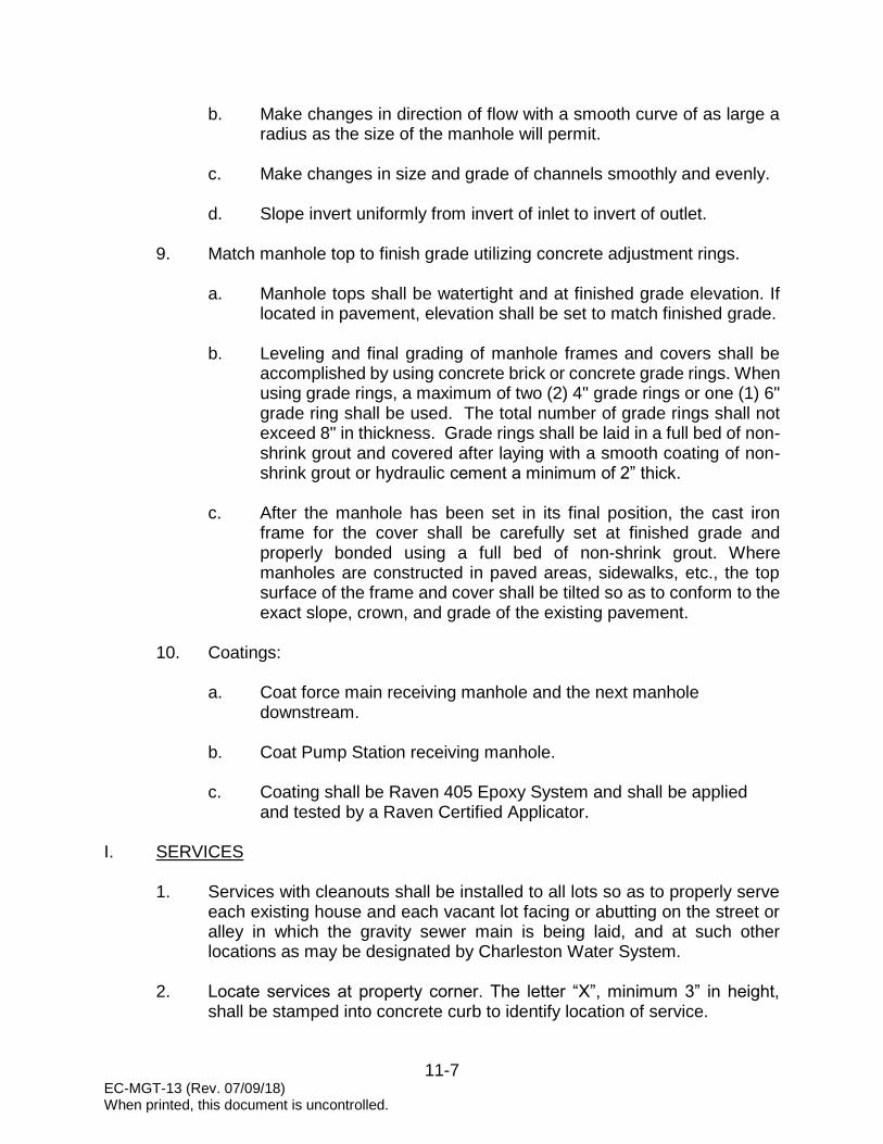
11-7 EC-MGT-13 (Rev. 07/09/18) When printed, this document is uncontrolled.
b. Make changes in direction of flow with a smooth curve of as large a radius as the size of the manhole will permit.
c. Make changes in size and grade of channels smoothly and evenly.
d. Slope invert uniformly from invert of inlet to invert of outlet.
9. Match manhole top to finish grade utilizing concrete adjustment rings. a. Manhole tops shall be watertight and at finished grade elevation. If
located in pavement, elevation shall be set to match finished grade.
b. Leveling and final grading of manhole frames and covers shall be accomplished by using concrete brick or concrete grade rings. When using grade rings, a maximum of two (2) 4" grade rings or one (1) 6" grade ring shall be used. The total number of grade rings shall not exceed 8" in thickness. Grade rings shall be laid in a full bed of non-shrink grout and covered after laying with a smooth coating of non-shrink grout or hydraulic cement a minimum of 2” thick.
c. After the manhole has been set in its final position, the cast iron frame for the cover shall be carefully set at finished grade and properly bonded using a full bed of non-shrink grout. Where manholes are constructed in paved areas, sidewalks, etc., the top surface of the frame and cover shall be tilted so as to conform to the exact slope, crown, and grade of the existing pavement.
10. Coatings:
a. Coat force main receiving manhole and the next manhole downstream.
b. Coat Pump Station receiving manhole.
c. Coating shall be Raven 405 Epoxy System and shall be applied
and tested by a Raven Certified Applicator.
I. SERVICES
1. Services with cleanouts shall be installed to all lots so as to properly serve each existing house and each vacant lot facing or abutting on the street or alley in which the gravity sewer main is being laid, and at such other locations as may be designated by Charleston Water System.
2. Locate services at property corner. The letter “X”, minimum 3” in height, shall be stamped into concrete curb to identify location of service.

11-8 EC-MGT-13 (Rev. 07/09/18) When printed, this document is uncontrolled.
3. In landscaped areas, cleanout caps shall be SMARTPlug as manufactured by GPK Products, Inc. Cleanouts shall terminate 3” to 6” below finish grade.
4. In paved areas, a PVC cleanout plug shall be installed 3” below finish grade
and covered by a Neenah R-1976 frame and lid. See Construction Details 5. Do not stack service lines vertically over the gravity sewer main. 6. Elder Valve Assembly
a. Install upstream of the cleanout at all residential and individual commercial services where Charleston Water System will not own and operate the water distribution system. See Construction Details
b. Provide tee handles and plunger assemblies, for the exact number of services as shown on the final approved Record Drawings, to the CWS inspector prior to Project Commissioning.
J. TESTING
1. Mandrel
After backfilling trenches, Contractor shall test PVC sewer pipe for initial diametric deflections by the use of a 5% mandrel which is acceptable to Charleston Water System. Mandrel shall be proof tested in the presence of the Engineer or his representative. The initial diametric deflection shall not exceed 5%. The mandrel pull shall be as described in the Ten State Standards. The Contractor shall not use any mechanical device in the mandrel pull.
2. Air Testing
The Contractor shall conduct low-pressure air tests on all completed sections of gravity sewer. The air test results will be used to evaluate materials and construction methods on the sewer line sections. The Contractor shall furnish an air compressor which will provide at least 300 cubic feet of air per minute at 100 psi, pressure gauges, air hoses, air hose connections and other equipment necessary to conduct the air test. Plugs in sewers 18" in size and larger shall be connected by cable for thrust reaction. The following provisions will be adhered to when conducting low-pressure air tests:

11-9 EC-MGT-13 (Rev. 07/09/18) When printed, this document is uncontrolled.
a. Equipment: 1. Plug Design
Either mechanical or pneumatic plugs may be used. All plugs shall be designed to resist internal testing pressures without the aid of external bracing or blocking. However, the Contractor should internally restrain or externally brace the plugs to the manhole wall as an added safety precaution throughout the test.
2. Singular Control
To facilitate test verification, all air used shall pass through a single, above ground control panel.
3. Air Control
The above ground air control equipment shall include a shut-off valve, pressure regulating valve, input pressure gauge, and a continuous monitoring, calibrated pressure gauge having a pressure range from 0 to at least 10 psi. Gauge shall display a NIST traceable calibration sticker with calibration date. The continuous monitoring gauge shall be no less than 4" in diameter with minimum divisions of 0.10 psi and an accuracy of plus or minus0.04 psi.
Acceptable Air Test Control Units: a. SEALCO Model 5012-100 Portable Low Pressure Air
Test Control Unit
b. Cherne Air-Loc Low Pressure Air-Testing System
c. Approved equal.
4. Separate Hoses
Two separate hoses shall be used to: (1) connect the control panel to the sealed line for introducing low-pressure air, and (2) a separate hose connection for constant monitoring of air pressure build-up in the line.

11-10 EC-MGT-13 (Rev. 07/09/18) When printed, this document is uncontrolled.
5. Pneumatic Plugs
If pneumatic plugs are utilized, a separate hose shall also be required to inflate the pneumatic plugs from the above ground control panel.
b. Test Procedure:
1. Plug Installation and Testing
After a manhole-to-manhole reach of pipe has been backfilled to final grade, prepared for testing, and the specified waiting period has elapsed, the plugs shall be placed in the line at each manhole and secured.
2. Line Pressurization Low pressure air shall be slowly introduced into the sealed line until the internal air pressure reaches 4.0 psi greater than the average back pressure of any groundwater above the pipe, but not greater than 9.0 psi. Immediately before testing, if groundwater is present, the groundwater elevation must be determined by appropriate means.
3. Pressure Stabilization
After achieving the required internal pressure, the air supply shall be throttled to maintain the pressure for at least 2 minutes. This time permits the temperature of the entering air to equalize with the temperature of the pipe walls.
4. Timing Pressure Loss
When temperatures have been equalized and the pressure stabilized, the air hose from the control panel to the air supply shall be shut off or disconnected. The continuous monitoring pressure gauge shall then be observed while the pressure is decreased to no less than 5.0 psi. At a reading of 4.0 psi, or any convenient observed pressure reading between 4.0 psi and 4.5 psi, timing shall commence with a stopwatch or other timing device that is at least 99.8% accurate. A predetermined required time for a specified pressure drop shall be used to determine the lines acceptability. Traditionally, a pressure drop of 1.0 psi has been specified. However, other pressure drop values may be specified, provided the required holding times are adjusted accordingly.

11-11 EC-MGT-13 (Rev. 07/09/18) When printed, this document is uncontrolled.
If the specified pressure drop is 0.5 psi rather than the more traditional 1.0 psi, then the required test times for a 1.0 psi pressure must be halved. Specifying a 0.5 psi pressure drop is desirable in that it can reduce the time needed to accomplish the air test without sacrificing test integrity. Therefore, the following subsections contain provisions for both the traditional 1.0 psi pressure drop and the more efficient 0.5 psi pressure drop. All requirements for a specified 0.5 psi drop are given in parentheses.
5. Determination of Line Failure
If the time shown in Table I (or Table II), for the designated pipe size and length, elapses before the air pressure drops 1.0 psi (or 0.5 psi); the section undergoing test shall have passed and shall be presumed to be free of defects. The test may be discontinued once the prescribed time has elapsed even though the 1.0 psi (or 0.5 psi) drop has not occurred.
6. Determination of Line Failure
If the pressure drops 1.0 psi (or 0.5 psi) before the appropriate time shown in Table I (or Table II) has elapsed, the air loss rate shall be considered excessive and the section of pipe has failed the test.
7. Line Repair or Replacement
If the section fails to meet these requirements, the Contractor shall determine at his own expense the source, or sources of leakage, and he shall repair or replace all defective materials and/or workmanship to the satisfaction of the Charleston Water System. The extent and type of repair, which may be allowed, shall be subject to the approval of Charleston Water System. The completed pipe installation shall then be retested and required to meet the requirements of the test.
8. Pressure Test Table
The following table is provided to assist in determining required test pressure where groundwater is present. Table is based on average groundwater depth above the pipe invert for the section of pipe to be tested. It is the responsibility of the Engineer to calculate proposed test pressure and submit to the Charleston Water System inspector for approval. In the absence of groundwater, minimum test pressure shall be 4.0

11-12 EC-MGT-13 (Rev. 07/09/18) When printed, this document is uncontrolled.
psi. Under no circumstances shall maximum test pressure exceed 9.0 psi.
Groundwater Above
Pipe Invert (ft)
Pressure (psi) 1 4.5 2 5.0 3 5.5 4 6.0 5 6.5 6 7.0 7 7.0 8 7.5 9 8.0
10 8.5 11 9.0
9. Specified Time Tables
To facilitate the proper use of this recommended practice for air testing, the following tables are provided. Table I contains the specified minimum times required for a 1.0 psi pressure drop from a starting pressure of at least 4.0 psi greater than the average back pressure of any groundwater above the pipe’s invert. Table II contains specified minimum times required for a 0.5 psi pressure drop from a starting pressure of at least 4.0 psi greater than the average back pressure of any groundwater above the pipe’s invert. Both Tables also include easy to use formulas for calculating required test times for various pipe sizes and odd lengths.
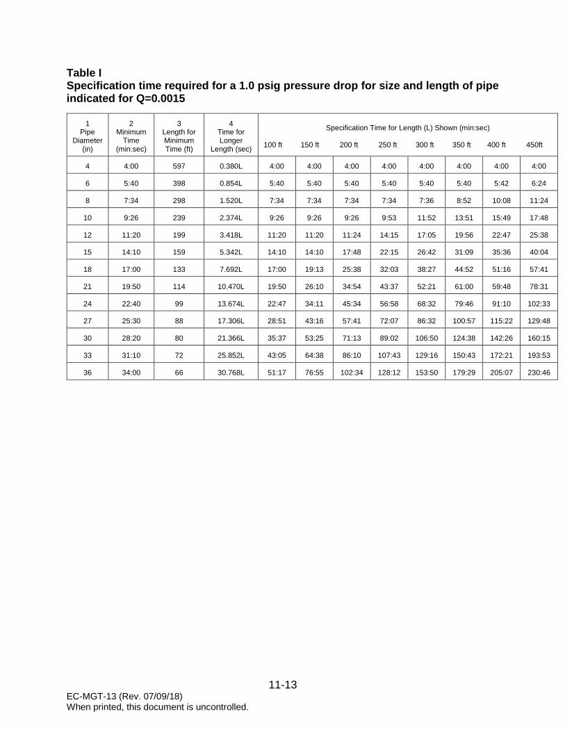
11-13 EC-MGT-13 (Rev. 07/09/18) When printed, this document is uncontrolled.
Table I Specification time required for a 1.0 psig pressure drop for size and length of pipe indicated for Q=0.0015
1
Pipe Diameter
(in)
2
Minimum Time
(min:sec)
3
Length for Minimum Time (ft)
4
Time for Longer
Length (sec)
Specification Time for Length (L) Shown (min:sec)
100 ft 150 ft 200 ft 250 ft 300 ft 350 ft 400 ft 450ft
4
4:00
597
0.380L
4:00
4:00
4:00
4:00
4:00
4:00
4:00
4:00
6
5:40
398
0.854L
5:40
5:40
5:40
5:40
5:40
5:40
5:42
6:24
8
7:34
298
1.520L
7:34
7:34
7:34
7:34
7:36
8:52
10:08
11:24
10
9:26
239
2.374L
9:26
9:26
9:26
9:53
11:52
13:51
15:49
17:48
12
11:20
199
3.418L
11:20
11:20
11:24
14:15
17:05
19:56
22:47
25:38
15
14:10
159
5.342L
14:10
14:10
17:48
22:15
26:42
31:09
35:36
40:04
18
17:00
133
7.692L
17:00
19:13
25:38
32:03
38:27
44:52
51:16
57:41
21
19:50
114
10.470L
19:50
26:10
34:54
43:37
52:21
61:00
59:48
78:31
24
22:40
99
13.674L
22:47
34:11
45:34
56:58
68:32
79:46
91:10
102:33
27
25:30
88
17.306L
28:51
43:16
57:41
72:07
86:32
100:57
115:22
129:48
30
28:20
80
21.366L
35:37
53:25
71:13
89:02
106:50
124:38
142:26
160:15
33
31:10
72
25.852L
43:05
64:38
86:10
107:43
129:16
150:43
172:21
193:53
36
34:00
66
30.768L
51:17
76:55
102:34
128:12
153:50
179:29
205:07
230:46

11-14 EC-MGT-13 (Rev. 07/09/18) When printed, this document is uncontrolled.
Table II Specification time required for a 0.5 psig pressure drop for size and length of pipe indicated for Q=0.0015
1
Pipe Diameter
(in)
2
Minimum Time
(min:sec)
3
Length for Minimum Time (ft)
4
Time for Longer Length
(sec)
Specification Time for Length (L) Shown (min:sec)
100 ft 150 ft 200 ft 250 ft 300 ft 350 ft 400 ft 450 ft
4
4:00
597
0.190L
4:00 4:00
4:00
4:00
4:00
4:00
4:00
4:00
6
4:00
398
0.427L
4:00
4:00
4:00
4:00
4:00
4:00
4:00
4:00
8
4:00
298
0.760L
4:00
4:00
4:00
4:00
4:00
4:26
5:04
5:42
10
4:43
239
1.187L
4:43
4:43
4:43
4:57
5:56
6:55
7:54
8:54
12
5:40
199
1.709L
5:40
5:40
5:42
7:08
8:33
9:58
11:24
12:50
15
7:05
159
2.671L
7:05
7:05
8:54
11:08
13:21
15:35
17:48
20:02
18
8:30
133
3.846L
8:30
9:37
12:49
16:01
19:14
22:26
25:38
28:51
21
9:55
114
5.235L
9:55
13:05
17:27
21:49
26:11
30:32
34:54
39:16
24
11:20
99
6.837L
11:24
17:57
22:48
28:30
34:11
39:53
45:35
51:17
27
12:45
88
8.653L
14:25
21:38
28:51
36:04
43:16
50:30
57:43
46:54
30
14:10
80
10.683L
17:48
26:43
35:37
44:31
53:25
62:19
71:13
80:07
33
15:35
72
12.926L
21:33
32:19
43:56
53:52
64:38
75:24
86:10
96:57
36
17:00
66
15.384L
25:39
38:28
51:17
64:06
76:55
89:44
102:34
115:23
3. Manhole Vacuum Test
When directed by Charleston Water System, manholes shall be tested via vacuum testing per ASTM C1244 except that the minimum test times shall be as defined in the Manhole Vacuum Test Table (test times modified from those in ASTM C-1244). Vacuum testing shall not be performed until the manhole is completely finished, including applying any protective coating where specified. Manholes shall be thoroughly cleaned of all silt, debris and foreign matter of any kind prior to the vacuum testing and then again prior to final inspection as required.
Vacuum tests shall be performed by placing the testing unit at the top of the
manhole in accordance with the manufacturer’s recommendations. A vacuum of 10 inches of mercury shall be drawn on the manhole, the valve on the vacuum line of the test unit closed, and the vacuum pump shut off. The time shall be measured for the vacuum to drop to 9 inches of mercury. The manhole shall pass if the time for the vacuum reading to drop from 10 inches of mercury to 9 inches of mercury meets or exceeds the test times indicated in Table 1 below. The test times in Table 1 are modified from those in ASTM C-1244. Table 1 shall be included on the Contractor’s test reports. Refer to ASTM C-1244 for further requirements.

11-15 EC-MGT-13 (Rev. 07/09/18) When printed, this document is uncontrolled.
Any leaks found during the vacuum testing shall be repaired by the Contractor in a manner approved by Charleston Water System. The manhole shall be vacuum tested again after such repairs are made until the manhole passes the vacuum test at no additional cost to the Owner.
Table 1 Manhole Vacuum Test Table
Manhole
Depth 36 42 48 54 60 66 72 84 96
(feet)
8 60 60 60 60 60 60 66 72 78
10 60 60 60 60 66 72 82 98 114
12 60 60 60 70 78 86 98 118 138
14 60 60 70 82 92 102 114 136 158
16 60 68 80 92 104 116 134 160 188
18 64 76 90 104 118 130 146 178 208
20 70 84 100 116 130 144 162 194 226
22 78 92 110 128 144 158 178 212 246
24 84 102 118 140 156 174 194 232 270
26 92 110 128 150 170 188 210 250 290
28 98 118 138 162 182 202 226 270 314
30 106 126 148 174 196 216 242 288 334
MINIMUM VACUUM TEST TIMES FOR VARIOUS MANHOLE DIAMETERS
Test Time (seconds)
Manhole Diameter (inches)
There shall be no groundwater infiltration or other leakage (active or evidence of being previously active) through the manhole walls, benches, inverts or pipe connections at the manholes. If leakage is found, it shall be eliminated with an appropriate grout or non-shrink cement mortar approved by Charleston Water System. Injection grouting (Avanti AV-202 Multigrout or approved equal) may be required to stop leaks around the pipe connections or in the invert channel or benches. Charleston Water System’s decision on how defective manholes are repaired shall be final. If any defective manholes are discovered after they have been installed or during the warranty period, they shall be repaired or replaced in a satisfactory manner at no additional cost to Charleston Water System. Repaired manholes, including those repaired during the warranty period, shall be vacuum tested again at no additional cost to Charleston Water System.
4. Manhole Coating Test Coating shall be tested for pinholes using approved spark test method. Applicator shall be responsible for correcting any defects found during testing.

11-16 EC-MGT-13 (Rev. 07/09/18) When printed, this document is uncontrolled.
K. CLOSED CIRCUIT TELEVISION (CCTV) INSPECTION
1. Intent
It is the intent of this specification to provide inspection criteria for all sanitary sewer pipelines installed as part of any new development project. This specification requires that the pipelines be inspected utilizing the Pipeline Assessment Certification Program (PACP) inspection standards and closed-circuit television techniques. This process has been developed to identify and locate any sewer line defects, determine corrective action and perform/document post-correction inspection. It is the responsibility of the Developer’s Engineer to ensure that these CCTV inspection procedures are performed. All costs associated with CCTV inspection are the responsibility of the Developer/Contractor.
2. Scope of work:
a. The CCTV Contractor shall video inspect all mainline sections from
manhole to manhole, and all service laterals from the right-of-way boundary to the mainline connection or manhole connection. Video inspection shall be performed immediately following construction and prior to the low-air pressure and deflection testing. It is in the best interest of the Developer/Utility Contractor to complete this task in a timely manner.
b. Prior to performing CCTV inspection activities, all sewer lines and service laterals designated to be televised shall be thoroughly cleaned. After cleaning, all equipment will be removed from the sewer line(s). Just prior to performing the video inspection procedure, water must be introduced into the nearest upstream manhole, and all cleanouts for laterals, until observed at the nearest downstream manhole.
3. CCTV and associated equipment: a. Television inspection equipment shall have an accurate footage
counter that will display on the monitor and record the camera distance from the centerline of the starting manhole. Distance measurements within the sewer line are to be accurate within 0.5% of the above ground measurement. Line segment inspections shall be made manhole to manhole. Prior to the beginning of each CCTV inspection, manhole identification numbers, as indicated on project drawing or as supplied by the Developer’s Engineer, will be displayed in the title and shall become a part of the video record. These manhole identification numbers shall correspond to the numbers shown on the project plans.

11-17 EC-MGT-13 (Rev. 07/09/18) When printed, this document is uncontrolled.
b. The camera shall be of the remotely operated pan and tilt type. The rotating camera and light head configuration shall have the capability of 360 degree rotating view angle and a minimum 270 degree pan angle with the capability to pan and tilt simultaneously while the transporter moves to view defects and voids around the entire diameter of the pipe wall, ensuring complete inspection of the mainline pipe, service laterals and any deficiencies.
c. The camera, television monitor, and other components shall be color. Geometrical distortion of the image shall not exceed one percent. To ensure peak picture quality throughout all conditions encountered, the color camera shall be equipped with the necessary circuitry to allow for the remote adjustment of the optical focus iris from the power control unit at the viewing station. A variable intensity control of the camera lights shall also be located at the viewing station.
d. All fog shall be evacuated from the pipeline and the pipeline kept clear of any fog during the CCTV inspection process.
e. Lighting and camera quality shall be suitable to allow a clear, in-focus picture for the entire inside periphery of pipelines extending at least ten (10) feet in front of the camera. In High Density Polyethylene (HDPE) or ductile iron poly-lined pipe, lighting should be sufficient enough to provide a clear view at least two (2) feet in front of the camera. The replay of the recorded video information shall be free of electrical interference and shall provide a clear stable image.
4. Execution: a. It is the responsibility of the Developer’s Engineer to provide the
CCTV Contractor with a set of Charleston Water System stamped “APPROVED FOR INSTALLATION” Construction Plans prior to CCTV inspection activities. Line segment inspections shall be made manhole to manhole.
b. Internal inspection of pipelines shall be performed by PACP certified
personnel, trained in the identification of pipe deficiencies and condition assessment utilizing closed-circuit television inspection equipment. A full 360 degree view of the pipe is required during inspection. The pipe must be clear and free of any dirt and/or debris. The CCTV Inspection Technician shall have full control of the movement of the television camera unit at all times. The travel speed of the camera shall be variable but uniform and shall not exceed 20 feet per minute (fpm). Any means of propelling the camera through the sewer line which would produce non-uniform or jerky movement

11-18 EC-MGT-13 (Rev. 07/09/18) When printed, this document is uncontrolled.
of the camera, will not be acceptable. The television system shall be capable of performing line segment inspection in increments of 400 feet with one setup.
c. Service laterals shall be inspected utilizing a CCTV inspection push
system, capable of inspecting up to one hundred (100) feet of pipe. All sanitary service lateral segments must be CCTV inspected from the top of the riser located at the property line, to the sewer mainline, noting type of cleanout installed, on the same disk for a continuous run. Continuous footage readings for identifying the location of defects must be accurate to within 3 percent tolerance. Deficiency identifications are to be called out and recorded to the nearest full foot. Any inaccuracy in the continuous footage meter, identified deficiencies, or lateral location descriptions which cause doubt as to the accuracy of the locations or total length shall render the line segment recording as unacceptable.
d. As directed by Charleston Water System, the Developer’s Engineer
or his representative, the camera shall be stopped to view and analyze conditions that appear unusual or uncommon. The CCTV Inspection Technician shall, at all times, be able to move the camera through the lines in either direction without the loss of quality in the video presentation.
e. The interior of the pipe shall be carefully inspected to determine the
location and extent of all deficiencies. Pipe conditions that result in a question of proper installation procedures shall be noted so that these conditions can be reviewed and, if necessary, corrected before actual acceptance of the sewer system.
f. CCTV inspections will take place immediately after construction and
prior to, or concurrent with, the low pressure air and mandrel testing. This will allow the correction of deficiencies found during the CCTV inspection process.
g. Access for CCTV inspection purposes shall be made via existing line
segment manholes and lateral cleanouts. Should access to a particular sewer segment be difficult, and where adjacent segments require television inspection, the CCTV Contractor may be allowed to complete the inspection of multiple sewer line segments with one setup. When multiple sewer line segments are inspected utilizing one setup, the CCTV Contractor shall zero the footage counter at each subsequent sewer manhole to establish a uniform starting point, Station 0+00, for each line segment televised.

11-19 EC-MGT-13 (Rev. 07/09/18) When printed, this document is uncontrolled.
h. At all defects and service connections, the camera shall be stopped and the pan and tilt features shall be used to obtain a clear picture. At each service lateral, the camera shall be panned to view up each lateral or point of connection. Make note of any deficiencies through the use of Data Collection Software.
i. CCTV Contractor shall record inspections in a PACP format and the
video shall be recorded in a high quality CD/DVD format. The title block shall include the following information: 1. Date and time of day.
2. PACP certified television operator’s identification (Name, ID
number, etc.).
3. Sewer segment number. Segment numbers shall be designated by the ENGINEER.
4. Upstream manhole number.
5. Downstream manhole number.
6. Size of sewer pipe.
7. Pipe material.
8. Closest cross street or address where the line segment is located.
9. Direction of movement of camera and direction of normal flow.
10. Location of service connections indicated by clock position and with counter distance in feet from beginning manhole’s centerline.
11. Location (start and end counter distances in feet from the beginning manhole’s centerline) and description of obstructions, structural defects, longitudinal and/or circumferential cracking, joints including open and/or offset joints, ovality, leakage or evidence thereof, break in connections, protruding connections, mineral deposits, roots, previous repairs, deposits on pipe walls, sags, and other abnormalities with respect to the sewer’s condition with counter distance in feet from the beginning manhole’s centerline.

11-20 EC-MGT-13 (Rev. 07/09/18) When printed, this document is uncontrolled.
12. CCTV Contractor’s log shall contain the same information.
j. CD/DVD shall visually display, at a minimum, the CCTV Contractor’s name, Project name, Charleston Water System Job Number and Extension, date of inspection, pipe segment number, manhole numbers or lateral lot numbers. The distance between manholes shall be verified by measuring tape. If the counter distance and the taping distance differ by more than 3 feet per 100 feet, the run shall be re-televised by CCTV Contractor.
k. CD/DVD shall be maintained and delivered in a hard case, which shall display the project name, Charleston Water System Job Number, date of inspection, manhole segment number(s) inspected, and camera operator’s identification. No segment shall be split between two disks. A disk may have multiple segments, so long as an entire section is on one disk. Original disks of all sections will be provided to the Charleston Water System Construction Inspector along with the respective television inspection field logs to be reviewed for completeness and soundness of construction prior to the Commissioning. Upon review and approval, copies will be provided to the Utility Contractor and Developer’s Engineer. Originals will remain the property of Charleston Water System.
l. If during video operations the television camera will not pass safely
through the entire sewer line segment being inspected, CCTV Contractor shall set up equipment in the reverse, so that the inspection can be performed from the opposite manhole; from downstream to upstream. Where an obstruction is encountered and a reverse set up is required, the distance shall be entered into the log and noted on the video format from which manhole the measurements are being made. If under the reverse setup the camera again fails to pass through the entire sewer line segment, the inspection shall be stopped. All obstructions in the sewer segment that prohibit passage of the television camera shall be immediately reported to the Engineer by the CCTV Contractor, referencing location and nature of the obstruction. No correction work shall proceed until Utility Contractor receives direction from the Developer’s Engineer or Charleston Water System Construction Inspector regarding removal or repair of deficiency.
m. Should CCTV Contractor’s televising equipment become lodged in any sewer line, it shall be removed by CCTV Contractor at his expense. This shall include, if necessary, excavation and repair of the sewer main and/or lateral, underground utility repairs, backfilling and surface restoration. Upon removal of CCTV equipment and repair, CCTV Contractor shall re-televise the line segment to

11-21 EC-MGT-13 (Rev. 07/09/18) When printed, this document is uncontrolled.
Developer’s Engineer or his representative that the line segment has been placed back into operational condition with no further deficiencies.
5. Acceptance: a. CCTV Contractor shall present inspection video and inspection logs
on CD/DVD disk(s). A continuous image in complete conformance with these specifications and with a full view of the internal pipe surface is required. CCTV Contractor shall re-clean and televise any segment for which the video does not present a clear image of 100% of the internal pipe surface at all times, and/or is accompanied by an incomplete inspection log.
b. Any of the following observations shall be considered defects:
1. Any bellies in a joint of pipe will be cause for rejection of the pipe segment.
2. Joint separations
3. Offset joints
4. Chips in pipe ends
5. Cracked or damaged pipe or evidence of the presence of an external object bearing upon the pipe (rocks, roots, etc.)
6. Infiltration
7. Roots
8. Debris or other foreign objects inside of pipe.
9. Other obvious deficiencies when compared to Approved Plans, Permits, and/or Minimum Standards.
c. The Utility Contractor shall be notified in writing of any deficiencies revealed by the CCTV inspection that will require repair. After repairs have been made, the line segment(s) shall be re-inspected at the Developer’s/Contractor’s expense. The CCTV inspection video shall be submitted to Charleston Water System for review upon completion of discrepancies.
Correction of any and all deficiencies must be corrected prior to
acceptance of the project by Charleston Water System.

12-1 EC-MGT-14 (Rev. 07/09/18) When printed, this document is uncontrolled.
SECTION 12
WASTEWATER COLLECTION SYSTEM FORCE MAIN DESIGN STANDARDS
The following information covers wastewater collection system force main design standards and is applicable to all developments requiring wastewater service from Charleston Water System. No deviation from these standards will be allowed without the expressed written consent of Charleston Water System. A. GENERAL
1. The following force main design standards are based on Federal, State and local health requirements and the requirements of Charleston Water System.
2. These design standards are applicable to all developments requiring
wastewater service from Charleston Water System.
3. Where it is necessary for wastewater force mains to cross surface water or wetlands, the engineer shall submit a proposed method of construction to Charleston Water System’s Engineering Department for review and approval prior to submitting plans for permitting.
4. As a general rule, Charleston Water System does not allow aerial force
main crossings. Examples of aerial crossings include, but are not limited to, force mains constructed on piers or pilings, and force mains attached to structures such as roadways, bridges or piers.
5. The preferred method of installation for force mains crossing surface water
or wetlands is by Horizontal Directional Drill or Jack and Bore. In either case, the engineer shall submit plans to Charleston Water System’s Engineering Department for review and approval prior to submitting plans for permitting.
B. DESIGN CRITERIA
1. Design force mains in accordance with the requirements of the South Carolina Department of Health and Environmental Control Standards for Wastewater Facility Construction: R.61-67, and the requirements of these Standards.
2. Size force mains to provide minimum velocity of two (2) feet per second at
design flow.

12-2 EC-MGT-14 (Rev. 07/09/18) When printed, this document is uncontrolled.
3. Use Hazen and Williams design coefficient: PVC: C=150, DIP: C=140, HDPE: C=155.
4. Minimum force mains diameter shall be 4”.
NOTE: Under conditions that arise from time to time, Charleston Water System will review submittals for grinder pump stations. When grinder pumps are approved by Charleston Water System, minimum force main diameter shall be 2”.
C. CAPACITY DESIGN
1. Size mains based on peak hourly flow projections two and one half (2.5) times the average daily flow projection.
2. Average daily flow projections for all domestic wastewater facilities shall be based on the type of facility to be served.
3. All flows shall comply with the unit contributory loading criteria, Appendix A of the South Carolina Department of Health and Environmental Control Standards for Wastewater Facility Construction: R.61-67.
D. SEPARATION OF WATER MAINS AND FORCE MAINS
1. Where possible, locate force mains at least 10’ feet horizontally away from water mains.
2. Should 10’ feet separation not be practical, then the force main may be
located closer provided:
a. It is laid in a separate trench.
b. It is laid in the same trench with the water main located at one side on a bench of undisturbed earth.
c. In either of the above cases, crown elevation of the force main shall
be at least 18" below bottom of water main.
3. Where force mains and water mains cross, the force main shall go under the water main and be at least 18" below the bottom of water main.
E. COVER
1. Provide suitable cover over all mains. Minimum cover depth as follows:
a. 12" diameter and smaller: 36".

12-3 EC-MGT-14 (Rev. 07/09/18) When printed, this document is uncontrolled.
b. 14" diameter and larger: 48".
c. All piping located within a public right-of-way shall be constructed in accordance with applicable permits and these Standards.
F. CONNECTION TO AN EXISTING GRAVITY SYSTEM
1. Connection to an existing gravity system shall be made at an existing manhole or by constructing a cut-in manhole.
2. Coat force main receiving manhole and the next manhole downstream.
G. CONNECTION TO AN EXISTING FORCE MAIN
1. Connection to an existing force main shall be made by installation of a tee or wye.
NOTE: Under conditions that arise from time to time, Charleston Water System will review submittals for direct taps.
2. Provide check valve and two (2) isolating plug valves. See Construction
Details H. VALVES
1. Air Release Valves:
a. Design force main to minimize the number of air release valves. b. Provide at high points in the force main.
c. Provide at maximum 3000’ intervals.
d. Maintain minimum 36” cover at location of air release valve.
e. Provide valve vault. See Construction Details
2. Cushioned Swing Check Valves:
a. Where a new force main connects to an existing force main, provide
cushioned swing check valve. See Construction Details b. Provide valve vault. See Construction Details

12-4 EC-MGT-14 (Rev. 07/09/18) When printed, this document is uncontrolled.
3. Plug Valves:
a. Force mains greater than 5,000’ in length, provide a plug valve at the halfway point.
b. Where no other force main isolation valve exists, provide plug valve
within 250’ of an air release valve.
c. Where a new force main connects to an existing force main, provide plug valve on each side of cushioned swing check valve. See Construction Details
d. Provide valve box and valve box protection ring. See Construction
Details

13-1 EC-MGT-15 (Rev. 07/09/18) When printed, this document is uncontrolled.
SECTION 13
WASTEWATER COLLECTION SYSTEM FORCE MAIN MATERIALS FOR CONSTRUCTION
The following information covers wastewater collection system force main materials for construction requirements and is applicable to all developments requiring wastewater service from Charleston Water System. No deviation from these requirements will be allowed without the expressed written consent of Charleston Water System. A. GENERAL
1. This section includes pipe and fitting material specifications, and joint material and encasement requirements.
2. All materials used in the construction of force mains shall be new and
unused when delivered on-site and shall be suitable for installation and operation under the conditions for which they are to be used.
B. PIPE AND FITTINGS
1. Polyvinyl Chloride (PVC) Pipe and Fittings:
a. 2” diameter: Pressure rated SDR21, ASTM D-2241.
b. 4" diameter and above: ANSI/AWWA C900/AWWA C905, Table 2, Pressure Class 150, and ASTM D-2241.
c. Use integral bell or coupling type with elastomeric gaskets. d. Factory-installed gaskets integral with the pipe.
e. Use ductile iron fittings with pressure rating of 150 psi: ANSI/AWWA
C110/A21.10, lined with Protecto 401, 40 mils nominal thickness.
f. Provide adaptor glands, gaskets, etc. as required to accommodate any differences in pipe and fitting dimensions.
2. Fusible Polyvinyl Chloride (FPVC) Pressure Pipe:
a. Fusible Polyvinyl Chloride pipe shall conform to AWWA C900 or AWWA C905, and/or ASTM D2241 or ASTM D1785 for IPS standard dimensionality, if applicable. Testing shall be in accordance with AWWA standards for all pipe types.
b. Fusible Polyvinyl Chloride pipe shall be extruded with plain ends.
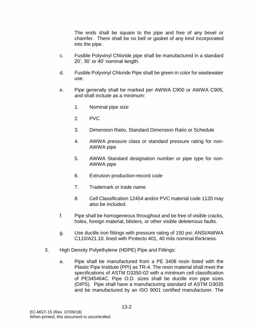
13-2 EC-MGT-15 (Rev. 07/09/18) When printed, this document is uncontrolled.
The ends shall be square to the pipe and free of any bevel or chamfer. There shall be no bell or gasket of any kind incorporated into the pipe.
c. Fusible Polyvinyl Chloride pipe shall be manufactured in a standard
20’, 30’ or 40’ nominal length.
d. Fusible Polyvinyl Chloride Pipe shall be green in color for wastewater use.
e. Pipe generally shall be marked per AWWA C900 or AWWA C905,
and shall include as a minimum:
1. Nominal pipe size 2. PVC
3. Dimension Ratio, Standard Dimension Ratio or Schedule
4. AWWA pressure class or standard pressure rating for non-
AWWA pipe
5. AWWA Standard designation number or pipe type for non-AWWA pipe
6. Extrusion production-record code
7. Trademark or trade name
8. Cell Classification 12454 and/or PVC material code 1120 may
also be included.
f. Pipe shall be homogeneous throughout and be free of visible cracks, holes, foreign material, blisters, or other visible deleterious faults.
g. Use ductile iron fittings with pressure rating of 150 psi: ANSI/AWWA
C110/A21.10, lined with Protecto 401, 40 mils nominal thickness.
3. High Density Polyethylene (HDPE) Pipe and Fittings:
a. Pipe shall be manufactured from a PE 3408 resin listed with the Plastic Pipe Institute (PPI) as TR-4. The resin material shall meet the specifications of ASTM D3350-02 with a minimum cell classification of PE345464C. Pipe O.D. sizes shall be ductile iron pipe sizes (DIPS). Pipe shall have a manufacturing standard of ASTM D3035 and be manufactured by an ISO 9001 certified manufacturer. The

13-3 EC-MGT-15 (Rev. 07/09/18) When printed, this document is uncontrolled.
pipe shall contain no recycled compounds except that generated in the manufacturer's own plant from resin of the same specification from the same raw material. The pipe shall be homogeneous throughout and free of visible cracks, holes, foreign inclusions, voids, or other injurious defects.
b. Fittings:
1. Butt fusion fittings shall be in accordance with ASTM D3261
and shall be manufactured by injection molding, a combination of extrusion and machining, or fabricated from HDPE pipe conforming to this specification. All fittings shall be pressure rated to provide a working pressure rating no less than that of the pipe. Fabricated fittings shall be manufactured using a McElroy Datalogger to record fusion pressure and temperature. A graphic representation of the temperature and pressure data for all fusion joints made producing fittings shall be maintained as part of the quality control. The fitting shall be homogeneous throughout and free of visible cracks, holes, foreign inclusions, voids, or other injurious defects.
2. Electrofusion fittings shall be PE3408 HDPE, Cell
Classification of 345464C as determined by ASTM D3350-02 and be the same base resin as the pipe. Electrofusion Fittings shall have a manufacturing standard of ASTM F1055.
3. Flanged and Mechanical Joint Adapters shall be PE 3408
HDPE, Cell Classification of 345464C as determined by ASTM D3350-02 and be the same base resin as the pipe. Flanged and mechanical joint adapters shall have a manufacturing standard of ASTM D3216. All adapters shall be pressure rated to provide a working pressure rating no less than that of the pipe.
4. Mechanical restraint for HDPE may be provided by
mechanical means separate from the mechanical joint gasket sealing gland. The restrainer shall provide wide, supportive contact around the full circumference of the pipe and be equal to the listed widths. Means of restraint shall be machined serrations on the inside surface of the restrainer equal to or greater than the listed serrations per inch and width. Loading of the restrainer shall be by a ductile iron follower that provides even circumferential loading over the entire restrainer. Design shall be such that restraint shall be increased with increases in line pressure.

13-4 EC-MGT-15 (Rev. 07/09/18) When printed, this document is uncontrolled.
Serrated restrainer shall be ductile iron ASTM A536-80 with a ductile iron follower; bolts and nuts shall be corrosive resistant, high strength alloy steel.
The restrainer shall have a pressure rating of, or equal to that of the pipe on which it is used or 150 PSI whichever is lesser. Restrainers shall be JCM Industries, Sur-Grip or approved equal.
Nominal Size (Inch)
Restraint Width (Inch)
Serrations Per Inch
4-6 1 ½ 8
8, 10 & 12” 1 ¾ 8
Pipe stiffeners shall be used in conjunction with restrainers. The pipe stiffeners shall be designed to support the interior wall of the HDPE. The stiffeners shall support the pipe’s end and control the “necking down” reaction to the pressure applied during normal installation. The pipe stiffeners shall be formed of 304 or 316 stainless steel to the HDPE manufacturers published average inside diameter of the specific size and DR of the HDPE. Stiffeners shall be by JCM Industries or approved equal.
4. Ductile Iron Pipe (DIP) and Fittings:
a. All Ductile Iron Pipe and fittings shall be lined with Protecto 401, 40
mils nominal thickness. b. Ductile Iron Pipe shall be in accordance with ANSI A21.50/AWWA
C150 and conform to the requirements of A21.51/AWWA C151. Push-on and restrained joint pipe shall have a minimum rated working pressure of 150 psi. All buried pipe shall be pressure class as follows.
Pipe Sizes
(inch) Pressure Class
(psi)
4-12 350
14-20 250
24 200
30-64 150
c. Ductile Iron Pipe and fittings shall be furnished with push-on joints,
push-on restrained joints, mechanical joints, and flanged joints as required. Pipe ends (spigot end, bell, and socket) for all pipes shall be gauged with suitable gauges at sufficiently frequent intervals to

13-5 EC-MGT-15 (Rev. 07/09/18) When printed, this document is uncontrolled.
ensure compliance to the standard dimensions of ANSI/AWWA C151/A1.5.
d. Push-on Joints shall conform to ANSI A21.11/AWWA C111.
e. Mechanical joints shall conform to AWWA C111. Bolts shall be high
strength low alloy steel per AWWA C111.
f. All buried ductile iron force main pipes shall be polyethylene wrapped. Thickness: 8 mils; Color: green (AWWA C105).
g. Acceptable products: American Cast Iron Pipe Company, Griffin Pipe
Company, U.S. Pipe Company, and McWane Cast Iron Pipe Company.
5. Restrained Joint Fittings:
a. Provide at each fitting and valve. Restrained joints shall be in
accordance with DIPRA, “Thrust Restraint Designed for Ductile Iron Pipe”. See Construction Details
b. Restrained joint pipe will be indicated clearly on plans. The location
and length of restrained joint pipe will be clearly marked on the drawings at all points where the direction or cross-sectional area of the pipe changes as well as at all bends, reducers, offsets, tees, wyes, dead ends, valves and transitions from PVC, FPVC or HDPE to Ductile Iron Pipe.
c. Acceptable products:
1. American Cast Iron Pipe – Fast Grip, Flex-Ring, Field Flex-
Ring or Lock-Ring 2. US Pipe – TR Flex or Field Lok 350 Gaskets
3. Griffin Pipe – Snap-Lok Restrained Joint
4. EBBA – Megalug Restraint Gland
5. Ford – Series 1500 Restraint Gland
6. Sigma – One-Lok Series SLD Restraint Gland
7. McWane – Sure Stop 350 Restraint Gasket
8. Cape Fear Industries – EZ Restraint Gland for Ductile Iron

13-6 EC-MGT-15 (Rev. 07/09/18) When printed, this document is uncontrolled.
C. METALLIC DETECTION TAPE
1. Provide 2” wide metallic detection tape on all buried piping.
a. Provide 5.0 mil overall thickness with no less than a 50 gauge solid aluminum foil core.
b. Foil to be visible from both sides.
c. No inks or printing extended to the edges of the tape.
d. Encase printing to avoid ink rub-off.
e. Tensile strength – 28 lbs/inch.
f. Use heat set Mylar inks.
2. Locate 12” below ground surface in pipe trench. 3. Color to be green.
4. Wording on tape to indicate “CAUTION SEWER LINE BURIED BELOW” at
no greater than 24” on center. D. TRACER WIRE
All force main installations shall include the installation of a locator wire. The locator wire shall be taped to the top of the pipe with polyethylene tape during the pipe laying operation. For force mains, which are installed by the open-trench method, the locator wire shall be stranded 12-gauge copper with insulation rated UF or USE by Underwriter’s Laboratories. For force mains, which are installed by a trenchless method, horizontal directional drilling or other, the locator wire shall be stranded 10-gauge stainless steel with insulation rated UF or USE by Underwriter’s Laboratories. Underground splice connections shall be minimized and shall be rated for direct burial service. The tracer wire shall be looped into “dummy” cast-iron water valve boxes with caps labeled “SEWER”, painted green, and at grade level, one being installed adjacent to the valve vault at the source pump station. Additional valve boxes shall be installed at intervals of no greater than every1000’ along the length of the force main, unless the main was installed by a trenchless method. A final valve box shall be installed at the discharge point of the force main, whether that is at a manhole or at a “tee” into another force main. The looped termination shall allow for the connection of an electronic locator transmitter.
E. AIR RELEASE VALVES
1. Provide combination air valve.

13-7 EC-MGT-15 (Rev. 07/09/18) When printed, this document is uncontrolled.
2. Maintain minimum 36” cover over force main at location of air valve.
3. The combination air valve shall be suitable for use at pressures up to 150 PSI.
4. The valve shall have Type 316 stainless steel body, cover and cover bolts
with a NPT inlet and outlet connection. Valves shall have a Type 316 stainless steel float and a replaceable seat of Buna-N or other suitable material. Venting orifice and internal linkage mechanism shall be Type 316 stainless steel.
5. Valve size shall be 1” or 2” size as shown on the plans, both sizes to be
supplied with 2” NPT pipeline connection. The distance from 2” pipeline connection to the top of the combination air valve shall not exceed 10”.
6. Valve shall be supplied with flushing attachments consisting of 2” stainless
steel inlet isolating ball valve, 1” stainless steel blow off ball valve and ½” stainless steel flushing ball valve and stainless steel pipe nipples and a 5’ rubber hose with quick connect couplings.
7. Valves shall be GA Industries Figure 959SS-ESF. See Construction Details
8. Provide valve vault:
a. Air release valves shall be enclosed in a 4' diameter precast manhole
with a flat slab top as a minimum standard. See Construction Details b. Provide manhole frame and vented cover. Frame and cover shall be
East Jordan Iron Works model 2029 or U.S. Foundry model 480 frame and RA-SSG cover. Cast into the center of the cover will be the letters CPW, 2” - 3” in height. Also cast into the cover will be the words SANITARY SEWER, 1 ½” - 2” in height.
c. Base shall be formed using solid concrete blocks set on a 12” deep
bed of compacted No. 57 stone. See Construction Details
d. Coatings:
1. Coat interior surfaces of air release valve vault. 2. Coating shall be Raven 405 Epoxy System, 120 mil nominal
thickness, and shall be applied by a Raven Certified Applicator.
3. Coating shall be tested for pinholes using approved spark test
method. Applicator shall be responsible for correcting any

13-8 EC-MGT-15 (Rev. 07/09/18) When printed, this document is uncontrolled.
defects found during testing. F. CUSHIONED SWING CHECK VALVES
1. Provide cast iron body with bronze seating ring and stainless steel shaft for
attachment of weight and lever with non-corrosive adjustable air cushioned shock chamber.
2. Mount the cushioned chamber to the side of the valve body with piston
operating in the chamber, which will prevent valve closing without any hammering action.
3. Shock absorption by air: Adjustable closing speed.
4. Approved manufacturer: G. A. Industries, Inc. Figure 250-D.
5. Provide valve vault:
a. Check valves shall be enclosed in a 4' diameter precast manhole
with a flat slab top as a minimum standard. See Construction Details b. Provide manhole frame and vented cover. Frame and cover shall be
East Jordan Iron Works model 2029 or U.S. Foundry model 480 frame and RA-SSG cover. Cast into the center of the cover will be the letters CPW, 2” - 3” in height. Also cast into the cover will be the words SANITARY SEWER, 1 ½” - 2” in height.
c. Base shall be formed using solid concrete blocks set on a 12” deep
bed of compacted No. 57 stone. See Construction Details G. PLUG VALVES
1. Provide cast iron body in accordance with ASTM A126. 2. Flanged end, ANSI 125 lbs. Standard, or mechanical joint.
3. Use drip tight shutoff plug mounted in stainless steel bearings.
4. Provide 1/8” thick hand welded in overlay, no less than 90% nickel content
on all surfaces contacting the plug face. Seat to be raised from the valve body and machined to a smooth finish.
5. Provide bolted bonnet design. Stem seals shall be provided in accordance
with AWWA C517.
6. Furnish lever actuator.

13-9 EC-MGT-15 (Rev. 07/09/18) When printed, this document is uncontrolled.
7. Approved manufacturer: DeZurik or Pratt/Milliken.
8. Provide valve box:
a. Valve box shall be full cast or ductile iron with iron covers suitable for heavy traffic use and conform to ASTM A-48, Class 20 Specifications.
b. Valve boxes shall be screw type and have a 5 1/4" inside shaft
diameter.
c. Have the word “SEWER” cast into the cover.
d. Coat box and cover with two (2) shop coats of bitumastic paint.
e. No part of the valve box is to rest on the buried valve.
f. Acceptable product: Products of Tyler Union #6850 Series, Bingham & Taylor #4905 Series of U.S. manufacture only, AFC Box with external stem and locking lid, and East Jordan Ironworks #8550 Series.
g. Provide at each valve box in unpaved areas a precast concrete
protection ring. See Construction Details
EC-MGT-16 (Rev. 07/09/18) When printed, this document is uncontrolled.
14-1
SECTION 14
WASTEWATER COLLECTION SYSTEM FORCE MAIN CONSTRUCTION PROCEDURES
The following information covers wastewater collection system force main construction procedures and is applicable to all developments requiring wastewater service from Charleston Water System. No deviation from these procedures will be allowed without the expressed written consent of Charleston Water System A. GENERAL
1. Construction of water and wastewater systems to be turned over to
Charleston Water System must be performed by a Charleston Water System Approved Contractor. The Approved Contractor lists for both Large Projects (those greater than $50,000) and Small Projects (those $50,000 and less) are available on the New Development page on our website. Requirements for being considered an Approved Contractor can be obtained by contacting the Assistant Director of Engineering and Construction by email at [email protected] or by telephone at (843) 727-6876.
2. Prior to construction activities taking place, the Developer’s Engineer shall
coordinate in advance a Pre-Construction Meeting with the assigned Charleston Water System Construction Inspector. The Developer, Developer’s Engineer, Approved Contractor(s), and Charleston Water System’s Construction Inspector shall be in attendance at a minimum.
3. If any requirements for carrying out project construction are not met,
Charleston Water System reserves the right to have the Developer’s Engineer issue a STOP WORK ORDER.
B. OPERATION OF CHARLESTON WATER SYSTEM VALVES
1. Only Charleston Water System personnel shall operate Charleston Water System valves or hydrants unless otherwise directed or approved by Charleston Water System.
2. Approval for non-Charleston Water System personnel to operate Charleston Water System valves or hydrants shall be determined on a case-by-case basis.
3. All hydrant and blow-off operations shall be done in a manner so that private property is not impacted and there shall be no flooding of streets or roadways or any other traffic problems created.

EC-MGT-16 (Rev. 07/09/18) When printed, this document is uncontrolled.
14-2
C. HANDLING OF MATERIALS
1. General:
a. Store rubber gaskets and polyethylene film under cover and out of direct sunlight. Do not store nuts, bolts, glands, and other accessories directly on the ground. Keep inside of pipe and fittings free of dirt and debris.
b. Keep valves off the ground and keep interior free of dirt and debris. Do not expose valve interior to direct sunlight.
c. Handle pipe so as to ensure delivery to the trench in sound,
undamaged condition.
d. Carry pipe into position.
e. Use pinch bars, slings or tongs for aligning or turning the pipe.
f. Use care not to damage Ductile Iron Pipe linings.
2. Polyvinyl Chloride (PVC) pipe:
a. Store in unit packages as received from manufacturer until just prior to use.
b. Stack units to prevent deformation to pipe barrels and bells.
c. Protect from direct sunlight by covering with opaque material.
3. Fusible Polyvinyl Chloride (FPVC) pipe:
a. Pipe lengths should be stored and placed on level ground. Pipe
should be stored at the job site in the unit packaging provided by the manufacturer. Caution should be exercised to avoid compression, damage, or deformation to the ends of the pipe. The interior of the pipe, as well as all end surfaces, should be kept free from dirt and foreign matter.
b. Pipe shall be handled and supported with the use of woven fiber pipe
slings or approved equal. Care shall be exercised when handling the pipe to not cut, gouge, scratch or otherwise abrade the piping in any way.
c. If pipe is to be stored for periods of one (1) year or longer, the pipe
should be shaded or otherwise shielded from direct sunlight.

EC-MGT-16 (Rev. 07/09/18) When printed, this document is uncontrolled.
14-3
Covering of the pipe, which allows for temperature build-up, is strictly prohibited. Pipe should be covered with an opaque material while permitting adequate air circulation above and around the pipe as required to prevent excess heat accumulation.
d. Pipe shall be stored and stacked per the pipe manufacturer’s
guidelines.
4. High Density Polyethylene (HDPE) pipe:
a. Pipe shall be delivered without, nicks, gouges, or other physical damage.
b. Pipe shall be stored on clean, level ground to prevent undue
scratching or gouging. If the pipe must be stacked for storage, such stacking shall be done in accordance with the pipe manufacturer’s recommendations. The pipe shall be handled in such a manner that it is not pulled over sharp objects or cut by chokers or lifting equipment.
c. Sections of pipe having been discovered with cuts or gouges in
excess of 10% of the pipe wall thickness shall be cut out and removed. The undamaged portions of the pipe shall be rejoined using the heat fusion joining method.
d. Fused segments of the pipe shall be handled so as to avoid damage
to the pipe. Chains or cable type chokers must be avoided when lifting fused sections of pipe. Nylon slings are preferred. Spreader bars are recommended when lifting long fused sections.
D. TRENCH EXCAVATION
This section of the Standards is provided to outline most types of laying conditions, but is not intended to cover all special laying conditions or the Engineer’s special requirements.
1. Trench excavation shall be made in open cut and true to the lines and
grades shown on the plans, unless boring is necessary or required. Banks of the trenches shall be cut in vertical, parallel planes, equidistant from the pipe centerline. The horizontal distance between such planes, or the overall width of trench, shall vary with the size of the pipe to be installed. The overall width of trench shall be as recommended by the manufacturer. See Construction Details
2. Bell holes for bell-and-spigot pipe shall be excavated at proper intervals so
that the barrel of the pipe will rest for its entire length upon the bottom of the

EC-MGT-16 (Rev. 07/09/18) When printed, this document is uncontrolled.
14-4
trench. Bell holes shall be large enough to permit proper installation of joints in the pipe.
3. When muck, quicksand, soft clay, swampy or other material unsuitable for
foundations or sub-grade is encountered, such material shall be removed and replaced with No. 57 stone.
4. After excavation, the area between the final pipe grade and the trench soil
bottom shall be filled with No. 57 stone as required, compacted to proper grade, and made ready for pipe laying.
5. Debris encountered in trench excavation shall be removed for the overall
width of trench which shall be as shown on the plans. It shall be removed to a depth of 6" below the bottom of the pipe for pipes smaller than 24" in size; 8" below the bottom of the pipe for pipes 24" to 36" in size; and 12" below the bottom of the pipe for pipes larger than 36" in size, if debris extends to such depth.
6. In all cases, materials deposited shall be placed so that in the event of rain,
no damage will result to the work. 7. The sides of all excavations shall be sufficiently sheeted, shored and braced
whenever necessary to prevent slides, cave-ins, settlements or movement of the banks and to maintain the excavation clear of obstructions. Maintain the walls of the excavation properly in place and protect all persons and property from injury or damage. Sheeting, shoring or bracing materials shall not be left in place unless as shown by the plans or permitted by Charleston Water System. All sheeting and bracing shall be left in place until the trench has been backfilled 1’ above the top of the pipe.
E. TRENCH BACKFILL
1. The backfilling of pipeline trenches shall be started immediately after the pipe work has been inspected. The initial backfill material, placed to a height of 1’ above the top of the pipe, shall consist of approved backfill material free from organic matter and deleterious substances, containing no rocks or lumps over 2" in any dimension.
It shall be carefully placed and compacted throughout entire area backfilled. Backfill the trench above the pipe zone with approved backfill material in lifts not exceeding 6" loose depth and compact each lift to a minimum of 95 percent of maximum density, as determined by ASTM D 1557, with mechanical vibrating or impact tampers.

EC-MGT-16 (Rev. 07/09/18) When printed, this document is uncontrolled.
14-5
2. Where pipe trenches are cut across or along pavement, the trenches shall be backfilled in accordance with applicable permits.
3. Backfilling around structures shall be done in the manner specified above
for pipe trenches by power tamping for the full depth of cut to the top of the finished grade.
4. All backfilling shall be done in such a manner as will not disturb or damage
the pipe or structure over or against which it is being placed. Any pipe or structure damaged or moved from its proper line or grade during backfilling operations shall be uncovered, repaired, and then re-backfilled as herein specified.
5. All excavations suspected of not meeting compaction requirements shall be tested for conformance by a Charleston Water System approved testing lab. Tests shall be performed at the locations and depths directed by Charleston Water System.
F. PIPE, VALVE AND APPURTENANCE INSTALLATION
1. General:
a. Inspect pipe for damage. Remove damaged and unacceptable pipe. Keep interior and joint surfaces clean and free of foreign materials. Securely close open ends of pipe, fittings, and valves when work is not in progress.
b. Replace pipe where any part of coating or lining is damaged.
c. Lower pipe and accessories into trench by means of derrick, ropes,
belt slings, or other equipment approved by the manufacturer.
d. Do not dump or drop any of the materials into the trench.
e. Except where necessary in making connections to other lines, lay pipe with the bells facing in the direction of laying.
f. Rest the full length of each section of pipe solidly on the pipe bed,
with recesses excavated to accommodate bells, couplings, and joints.
g. Bell pipe using manufacturer’s approved leverage bar. Do not use
machinery to bell pipe. Home line is to be clearly visible when pipe is joined.
EC-MGT-16 (Rev. 07/09/18) When printed, this document is uncontrolled.
14-6
h. Do not lay pipe in water or when trench conditions are unsuitable for the work. Keep water out of the trench until jointing is completed.
i. Re-lay pipe that has the joint disturbed after laying.
j. Valves shall be carefully handled, cleaned and checked for operation
prior to backfilling. Care shall be taken to ensure that no dirt, rock, or other obstacles that would interfere with the operation are left in the valve. Valves shall be installed in a position such that the plane of operation or rotation for the operating nut is parallel to the ground surface.
2. Alignment and Grade
a. Fittings, valves and other appurtenances shall be located where shown on the approved plans, with the pipe being cut if necessary to assure accurate placement. Install the pipe, valves, and appurtenances to the alignment and profile shown on the approved drawings.
b. Pipe lines intended to be straight shall be so laid.
c. Where vertical or horizontal alignment requires deflection from straight lines or grade, do not exceed 75% of maximum deflection recommended by the pipe manufacturer or AWWA Standard 600.
d. If alignment requires deflection exceeding recommended limits,
furnish bends to provide angular deflections within the allowable limits.
3. Jointing Pipe, Valves and Appurtenances:
a. Mechanical, Push-On, and Restrained Joint
Join pipe with mechanical or push-on type joints in accordance with the manufacturer’s recommendations. Provide all special tools and devices, such as special jacks, chokers, and similar items required for proper installation. Lubricants for the pipe gaskets shall be used and shall be manufacturer’s standard. All mechanical joints used on taps and valves shall have restraining glands.
b. Flanged
Prior to connecting flanged pipe, the faces of the flanges shall be thoroughly cleaned of all oil, grease, and foreign material. The rubber gaskets shall be checked for proper fit and thoroughly

EC-MGT-16 (Rev. 07/09/18) When printed, this document is uncontrolled.
14-7
cleaned. Care shall be taken to ensure proper seating of the flange gasket. Bolts shall be tightened so that the pressure on the gasket is uniform. Torque-limiting wrenches shall be used to ensure uniform bearing insofar as possible. If joints leak when the hydrostatic test is applied, the gaskets shall be removed and reset and bolts re-tightened.
4. Installation of Restraining Glands:
a. Adjoining surfaces shall be clean, lubricated and meet the requirements of ANSI/AWWA C111/A21.11.
b. Install using assembly recommendations established in
ANSI/AWWA C111/A21.11 as well as installation instructions provided by the manufacturer.
c. If twist-off nuts are provided, tighten screws until nuts breaks loose.
5. Cutting pipe:
a. Cut pipe neatly without damage to the pipe.
b. Unless otherwise recommended by the pipe manufacturer, cut pipe
with milling type cutter, rolling pipe cutter, or abrasive saw cutter. Do not flame cut. Use wheel cutters when practical. Cuts must be even and perpendicular with length of pipe. Dress cut ends of pipe in accordance with manufacturer’s directives for the type of joint to be made. Cut ends and rough edges should be ground smooth.
c. DIP and PVC pipe with push-on type connection, the cut end must
be slightly beveled.
6. Polyethylene Encasement
All valves, ductile iron force mains, fittings, and appurtenances are to be wrapped in a linear low-density polyethylene film, 8 mil, color green, in accordance with ANSI Standard A21.5 (AWWA C105). Close all open ends and damaged areas securely with poly-tape. If damaged polyethylene film cannot be repaired, replace with new film.

EC-MGT-16 (Rev. 07/09/18) When printed, this document is uncontrolled.
14-8
G. CONNECTION TO AN EXISTING GRAVITY SYSTEM 1. Connection of new force main to an existing gravity system shall be made
at an existing manhole or by constructing a cut-in manhole.
a. Existing manhole:
1. Connection to an existing manhole shall be made in the presence of the Charleston Water System inspector.
2. Connection shall be made at existing flow line. See
Construction Details 3. New holes in manholes shall be core drilled.
4. When connecting to an existing manhole, temporarily block
and/or divert sewage flows. Use high early strength cement to form proper channels with minimum interruption of service.
5. Seal around new pipe. See Construction Details
b. Cut-in manhole:
1. Temporarily block and/or divert sewage flows. Cut out length
of existing pipe to accept new pipe in manhole. 2. If benches are pre-formed, insert short section of PVC pipe in
the existing holes and seal. Lower bottom section of manhole into hole and sleeve to existing piping. See Construction Details
3. If benches are not pre-formed, cut the PVC pipe to form the
channel and insert the required length of pipe through the holes in the bottom section of the manhole, set to match existing slope, and seal. Lower the assembly into the hole, sleeve to existing piping, and unblock sewage flows. Using high early strength cement, form benches as in typical manholes. See Construction Details
c. Coatings:
1. Coat force main receiving manhole and the next manhole
downstream.
EC-MGT-16 (Rev. 07/09/18) When printed, this document is uncontrolled.
14-9
2. Coating shall be Raven 405 Epoxy System, 120 mil nominal thickness, and shall be applied by a Raven Certified Applicator.
3. Coating shall be tested for pinholes using approved spark test
method. Applicator shall be responsible for correcting any defects found during testing.
H. CONNECTION TO AN EXISTING FORCE MAIN
1. Connection to an existing force main shall be made by installation of a tee or wye.
NOTE: Under conditions that arise from time to time, Charleston Water System will review submittals for direct taps. When approved by Charleston Water System, force mains less than 6” in diameter; use 316 stainless steel tapping saddles. Force mains 6” in diameter and larger; use 316 stainless steel tapping sleeves.
2. Provide cushioned swing check valve with isolating plug valve on each side
of check valve. See Construction Details I. INSTALLATION OF AIR RELEASE VALVES
1. Maintain minimum 36” cover over force main at location of air release valve. 2. Force mains less than 6” in diameter; install air release valve using 316
stainless steel tapping saddle.
3. Force mains 6” in diameter and larger; install air release valve using 316 stainless steel tapping sleeve.
4. Provide 316 stainless steel isolation ball valve. See Construction Details
5. Set valve plumb.
6. Provide valve vault:
a. Air release valves shall be enclosed in a 4’ diameter precast manhole
with a flat top slab as a minimum. Base shall be formed using solid concrete blocks set on a 12” deep bed of compacted No. 57 stone. See Construction Details
b. Provide manhole frame and vented cover.

EC-MGT-16 (Rev. 07/09/18) When printed, this document is uncontrolled.
14-10
c. Coatings:
1. Coat interior surfaces of air release valve vault. 2. Coating shall be Raven 405 Epoxy System, 120 mil nominal
thickness, and shall be applied by a Raven Certified Applicator.
3. Coating shall be tested for pinholes using approved spark test
method. Applicator shall be responsible for correcting any defects found during testing.
J. INSTALLATION OF CUSHIONED SWING CHECK VALVES
1. Maintain minimum 36” cover over force main at location of check valve. 2. Set valve level.
3. Mount the cushioned chamber to the side of the valve body with piston
operating in the chamber, which will prevent valve closing without any hammering action.
4. Provide valve vault:
a. Check valves shall be enclosed in a 4’ diameter precast manhole
with a flat top slab as a minimum. Base shall be formed using solid concrete blocks set on a 12” deep bed of compacted No. 57 stone. See Construction Details
b. Provide manhole frame and vented cover.
K. INSTALLATION OF PLUG VALVES
1. Maintain minimum 36” cover over force main at location of plug valve. 2. Provide valve box. No part of the valve box is to rest on the buried valve.
3. Provide at each valve box in unpaved areas a precast concrete protection
ring. See Construction Details L. METALLIC DETECTION TAPE INSTALLATION 1. Provide 2” wide metallic detection tape on all direct buried force mains. 2. Locate 12” below ground surface in pipe trench.

EC-MGT-16 (Rev. 07/09/18) When printed, this document is uncontrolled.
14-11
M. TRACER WIRE INSTALLATION
1. All force main installations shall include the installation of a locator wire. The locator wire shall be taped to the top of the pipe with polyethylene tape during the pipe laying operation. For force mains, which are installed by the open-trench method, the locator wire shall be stranded 12-gauge copper with insulation rated UF or USE by Underwriter’s Laboratories. For force mains, which are installed by a trenchless method, horizontal directional drilling or other, the locator wire shall be stranded 10-gauge stainless steel with insulation rated UF or USE by Underwriter’s Laboratories. Underground splice connections shall be minimized and shall be rated for direct burial service. The tracer wire shall be looped into “dummy” cast-iron water valve boxes with caps labeled “SEWER”, painted green, and installed at grade level, one being installed adjacent to the valve vault at the source pump station. Additional valve boxes shall be installed at intervals of no greater than every1000’ along the length of the force main, unless the main was installed by a trenchless method. A final valve box shall be installed at the discharge point of the force main, whether that is at a manhole or at a “tee” into another force main. The looped termination shall allow for the connection of an electronic locator transmitter.
2. Prior to acceptance of the wastewater force main by Charleston Water
System, the Contractor shall demonstrate that the locator wire functions properly. The Contractor shall use one of several commercially available utility locating instruments to energize and trace the locator wire. When the wastewater force main is installed in the road shoulder, green-marking flags (pin flags) shall be installed along the length of the wastewater main at intervals of no greater than twenty (20’) feet. Where the force main is installed under concrete or asphalt, green marking paint shall be used. Testing of the locator wire and installation of the marking flags shall be done prior to scheduling a final inspection of the wastewater system
N. JACK AND BORE
1. General
a. Description
This section covers the work necessary to furnish and install steel casings and carrier pipes under surface structures, where indicated, as specified herein, and as needed for a complete and proper installation.
b. Safety
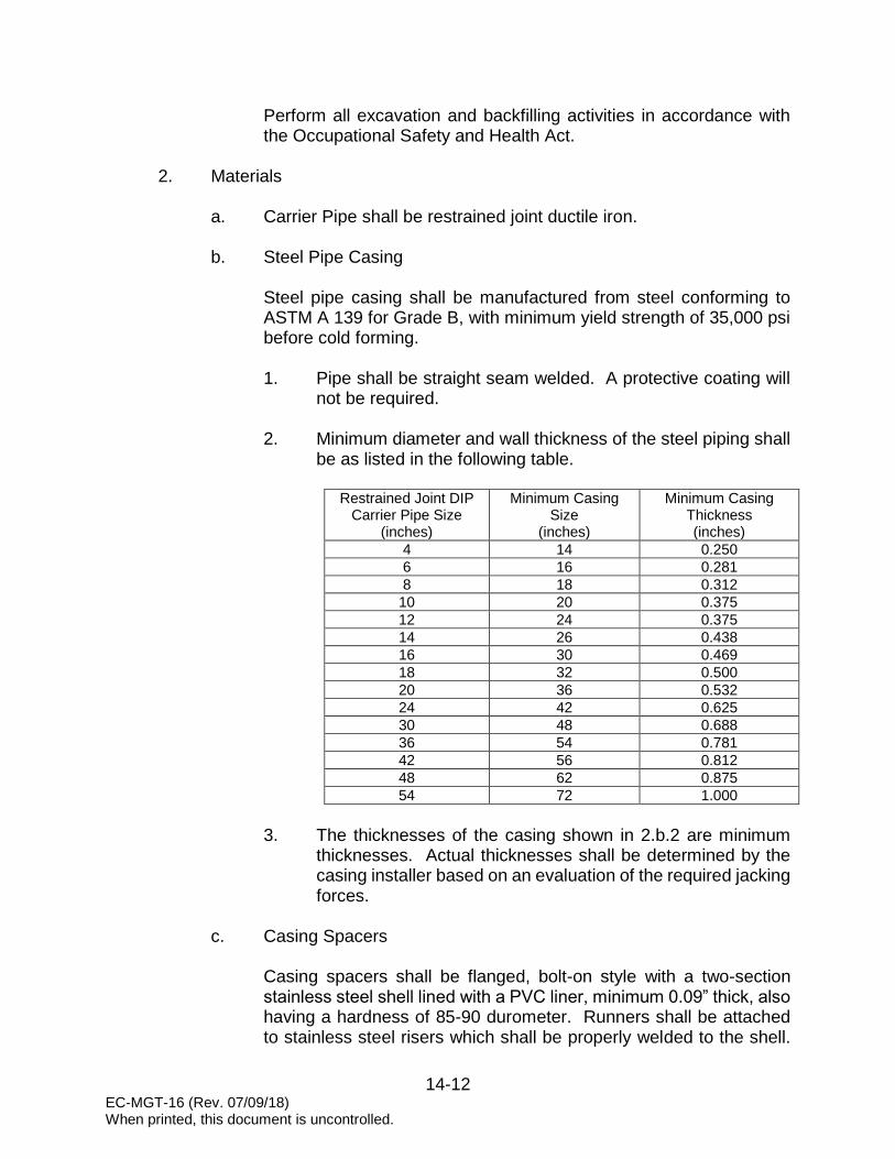
EC-MGT-16 (Rev. 07/09/18) When printed, this document is uncontrolled.
14-12
Perform all excavation and backfilling activities in accordance with the Occupational Safety and Health Act.
2. Materials
a. Carrier Pipe shall be restrained joint ductile iron.
b. Steel Pipe Casing
Steel pipe casing shall be manufactured from steel conforming to ASTM A 139 for Grade B, with minimum yield strength of 35,000 psi before cold forming. 1. Pipe shall be straight seam welded. A protective coating will
not be required.
2. Minimum diameter and wall thickness of the steel piping shall be as listed in the following table.
Restrained Joint DIP
Carrier Pipe Size (inches)
Minimum Casing Size
(inches)
Minimum Casing Thickness (inches)
4 14 0.250 6 16 0.281 8 18 0.312
10 20 0.375 12 24 0.375 14 26 0.438 16 30 0.469 18 32 0.500 20 36 0.532 24 42 0.625 30 48 0.688 36 54 0.781 42 56 0.812 48 62 0.875 54 72 1.000
3. The thicknesses of the casing shown in 2.b.2 are minimum
thicknesses. Actual thicknesses shall be determined by the casing installer based on an evaluation of the required jacking forces.
c. Casing Spacers
Casing spacers shall be flanged, bolt-on style with a two-section stainless steel shell lined with a PVC liner, minimum 0.09” thick, also having a hardness of 85-90 durometer. Runners shall be attached to stainless steel risers which shall be properly welded to the shell.

EC-MGT-16 (Rev. 07/09/18) When printed, this document is uncontrolled.
14-13
The height of the runners and risers shall be manufactured such that the pipe does not float in the casing. Casing spacers shall be as manufactured by Cascade Waterworks Manufacturing Company, Contractors Manufacturing, Inc., or approved equal.
3. Execution
a. Installation of Steel Pipe Casing
Installation of steel pipe casing shall be by the dry bore method at locations as shown on the Contract Drawings and approved by the applicable permits. Installation of steel pipe casing shall be in accordance with applicable regulations, the Contract Drawings, these specifications, and any permits required with respect to the particular boring.
1. Boring Pit and Receiving Pit
The boring pit shall be solid sheeted, braced, and shored as necessary to provide a safe operation. The Contractor shall take all precautions, and comply with all local, state and federal requirements as may be necessary to protect private property, public property and/or existing utilities. Maintain in dry condition by use of pumps, drains or other approved method.
The receiving pit shall be constructed in accordance with the Contract Drawings and applicable permits.
2. Line and Grade
The Contractor shall set the boring rig so that after the casing is complete, and the carrier pipe is installed, the invert of the pipe shall conform to grade and alignment as shown on the Contract Drawings. As the casing is installed, Contractor shall check the horizontal and vertical alignment frequently. Contractor shall install the boring at a 90-degree angle to the crossing unless permitting authority approves a different specific angle of crossing. The depth shall be a minimum depth as prescribed by the governing authority unless a deeper depth is dictated by design.
3. Boring
In all cases, jacking and boring of the casing pipe shall be accomplished by the dry jack and bore method without jetting,

EC-MGT-16 (Rev. 07/09/18) When printed, this document is uncontrolled.
14-14
sluicing, or wet boring. For casing pipes 48” in diameter and larger, a closed face shield bore head shall be utilized in front of the casing. For casing pipes less than 48” in diameter, the casing may be installed via open face method whereby the hole shall be bored and cased through the soil by a cutting head on a continuous auger mounted inside the casing pipe. The distance between the leading end of the first auger section and the leading end of the casing shall be as necessary to maintain a solid plug of spoil material inside the forward portion of the casing. At no time during the operation shall the auger head be allowed to extend out in front of the casing being installed. The boring of the hole and jacking of the casing pipe shall be done simultaneously, with continuous installation, until the casing pipe is in final position.
4. Dewatering
Contractor shall fully investigate the location of all jack and bores for the project and determine required dewatering methodologies for each location in order to provide for and conduct a dry jack and bore. Contractor shall submit plans and specifications for dewatering to the Engineer for approval prior to beginning the process (for railways, railway authority must also approve). Pumps of sufficient capacity to handle the flow shall be maintained at the site, provided the Contractor has received approval from the engineer to operate them. Pumps in operation shall be constantly attended on a 24-hour basis until, in the sole judgment of the DOT or railway authority; the operation can be safely halted. When dewatering, a process for monitoring any settlement of tracks, roads, or structures must be in place. Prior to commencing boring, the Contractor shall verify, with acceptance by the Engineer, the absence of groundwater to below the lowest elevation of the casing at each entry/exit pit and as necessary along the casing route.
5. Diameter of Hole
Bored installations shall have a bored hole no more than 1” greater than outside diameter of the casing pipe to be installed. In the event that voids are detected, the voids shall be grouted.
6. Casing Pipe Length

EC-MGT-16 (Rev. 07/09/18) When printed, this document is uncontrolled.
14-15
Lengths of casing pipe shall be as long as practical for site conditions. Joints between lengths shall be completely welded in accordance with American Welding Society recommended procedures. Prior to welding joints, the Contractor shall ensure that both ends of the casing sections being welded are square. The length of the casing shall be such that each end of the casing shall extend a minimum of 6’ beyond the edge of pavement/back of curb of a paved roadway, or if railway installation, in accordance with requirements of the railway authority.
7. Lubricant
The Contractor shall plan to use a casing lubricant, such as bentonite, in the event excessive frictional forces jeopardize the successful completion of the casing installation.
8. Jacking
Once the jacking procedure has begun, it shall be continued without stopping until the boring and jacking operation is complete.
9. Installation of the Carrier Pipe
a. Inspect carefully, ensuring that all foreign material is
removed from the casing and the casing meets alignment criteria for the type of carrier pipe being used.
b. The casing shall be installed as closely to grade as
possible with no more deviation than can be adjusted with spacers to achieve the carrier pipe design grade.
c. Install casing spacers on the carrier pipe per the
manufacturer's instructions. See Construction Details
d. Provide a minimum of one spacer per ten linear feet of pipe.
e. Install the carrier pipe in the casing ensuring each joint is pushed "home" before the joint is installed into the casing.
f. Provide centered and restrained configuration.

EC-MGT-16 (Rev. 07/09/18) When printed, this document is uncontrolled.
14-16
10. End Seals
Grout each end of the casing with concrete brick and Type II concrete in such a manner to prevent the infiltration of foreign materials into the casing pipe, but allowing leakage to pass in the event of a carrier pipe break.
b. Rights-of-Way, Easements, and Permits
Prior to the beginning of the Work, consult with the Engineer to determine that all rights-of-way, easements, permits, or other legalities are in order and become familiar with the requirements thereof. Confine the Work as required to comply with such requirements. Any encroachment beyond such limits shall be the Contractor's responsibility.
c. Conflict of Specifications
Where laws or orders of public authority prescribes a higher degree of protection than specified herein, then the higher degree so prescribed shall be deemed a part of this specification and govern the specific installation.
O. HYDROSTATIC TESTING
1. Conduct hydrostatic testing in accordance with AWWA C600.
a. Conduct tests on each line or valved section of line. b. Clean and flush line of dirt and foreign material. c. Slowly fill main in order to expel air from the main through the air
release valves or other appurtenance.
d. Tests are to be conducted in the presence of the Developer’s Engineer or his representative and witnessed by a Charleston Water System representative.
2. Pressure tests:
a. Pressure leakage test shall be conducted in accordance with AWWA
C600. Each section of the pipeline shall be subjected to and successfully meet a pressure test of 150% of its working pressure, but not less than 100 psi. The line shall be slowly filled with water and all air expelled through the air valves or other means.

EC-MGT-16 (Rev. 07/09/18) When printed, this document is uncontrolled.
14-17
c. A suitable test pump, furnished by the Contractor, shall be connected to the line by means of a tap in the line, or other suitable method, and the proper test pressure slowly applied to the line. The test pressure, +/- 5 psi, shall be maintained for at least two (2) hours. Leaks, if found, shall be immediately repaired. The Developer’s Engineer or his representative shall be present on site and confirm the test results.
c. Replace defective pipe, joints, fittings and valves with new material and repeat the test until results are satisfactory.
3. Leakage test:
a. Conduct leakage test in conjunction with pressure test. b. Testing allowance shall be defined as the maximum quantity of
makeup water that is added into a pipeline undergoing hydrostatic pressure testing, or any valved section thereof, in order to maintain pressure within +/- 5 psi of the specified test pressure (after the pipeline has been filled with water and the air has been expelled). No pipe installation will be accepted if the quantity of makeup water is greater than that determined by the following formula:
000,148
PSDL
Where:
L = Allowable Leakage, in gallons per hour S = Length of Pipe tested, in feet D = Nominal Diameter, in inches P = Average test pressure, in psig
c. Should test disclose leakage greater than that specified above,
repair, or if necessary, remove and replace the defective joint or valve until the leakage is within the specified allowance.

15-1 EC-MGT-17 (Rev. 07/09/18) When printed, this document is uncontrolled.
SECTION 15
WASTEWATER COLLECTION SYSTEM PUMP STATION DESIGN STANDARDS
The following information covers wastewater collection system pump station design standards and is applicable to all developments requiring wastewater service from Charleston Water System. No deviation from these standards will be allowed without the expressed written consent of Charleston Water System. A. GENERAL
1. The following wastewater pump station design standards are based on Federal, State and local health requirements and the requirements of Charleston Water System.
2. These design standards are applicable to all developments requiring
wastewater service from Charleston Water System.
3. Design pump station in accordance with the requirements of the South Carolina Department of Health and Environmental Control Standards for Wastewater Facility Construction: R.61-67, and the requirements of these Standards.
B. CAPACITY DESIGN
1. Average daily flow projections for all domestic wastewater facilities shall be based on the type of facility to be served.
2. All flows shall comply with the unit contributory loading criteria, Appendix A
of the South Carolina Department of Health and Environmental Control Standards for Wastewater Facility Construction: R.61-67.
3. Size pump stations based on peak hourly flow projection two and one half
(2.5) times the average daily flow projection.
4. When designing pumps, consideration is to be given to the ultimate capacity of the pump station, in accordance with Charleston Water System’s Master Plans.
C. PUMP STATION DESIGN
1. Pumps: a. Provide at least two (2) pumps of equal capacity, each capable of
handling the design peak flow.

15-2 EC-MGT-17 (Rev. 07/09/18) When printed, this document is uncontrolled.
b. Pumps shall be designed to operate in a lead-lag sequence and be on an alternating cycle.
c. Pumps shall have an operating point at or near peak efficiency.
d. Pumps shall be non-overloading for all duty points.
e. Pump suction and discharge piping shall be at least 4" in diameter.
NOTE: Under conditions that arise from time to time, Charleston Water System will review submittals for pump stations with grinder pumps. When grinder pumps are approved by Charleston Water System, pump suction and discharge piping shall be at least 2” in diameter.
f. Provide a swing check valve, plug valve, and pressure gauge
connection on each pump discharge line. See Construction Details
2. Wetwell:
a. Normal operating volume shall prevent any one pump from starting more than six (6) times per hour.
b. Minimum allowable wetwell diameter shall be 8'-0".
c. Maximum allowable depth shall be 26’ below finished grade.
d. Size the wetwell based on the following formula:
SSQ
TV
11
Where:
V = Effective volume of wetwell, in gallons
T = Time for one pump cycle, in minutes
Q = Pumping rate, in gallons per minute S = Peak flow into wetwell, in gallons per minute

15-3 EC-MGT-17 (Rev. 07/09/18) When printed, this document is uncontrolled.
e. Wetwell level settings:
1. Distance between pump “OFF”and lead pump “ON”: minimum as specified by the pump manufacturer, or as calculated for cycle time; whichever is greater.
2. Distance between lead pump “ON” and lag pump “ON”: 6"
minimum.
3. Distance between lag pump “ON” and alarm “ON”: 6" minimum.
4. Distance between alarm elevation and inlet pipe: 12"
minimum.
f. Top of wetwell slab shall be set to provide positive drainage away from the station and minimize flooding. At a minimum, top of slab shall be 6” above centerline elevation of public access road.
3. Pump Station Site:
a. Minimum property size: 50' x 50'. b. Site shall be asphalt paved. Provide 6” stone aggregate base with
geofabric underlayment and 2” asphalt cover. See Construction Details
c. Design pump station site layout to allow access of service trucks to
the pump station wetwell.
d. Provide receiving manhole on influent line within pump station fence.
e. Provide by-pass connection. See Construction Details
f. Provide a transfer switch for a portable generator.
g. No overhead power line will be allowed to cross the site.
h. The station shall have a 1” copper water service terminated in a Charleston Water System water meter box. See Construction Details
i. Fencing:
1. Site shall be secured by a 6’ high chain link fence.

15-4 EC-MGT-17 (Rev. 07/09/18) When printed, this document is uncontrolled.
NOTE: Brick fences will be reviewed on a case-by-case basis and are subject to the approval of Charleston Water System. Wooden fences shall not be allowed.
2. Provide vehicle access gate and personnel access gate.
Design vehicle access gate to allow entrance of service trucks without blocking the main roadway. See Details.
j. Access road:
1. Site shall be serviced by an asphalt road with top of road
above the 25-year flood elevation. Road and site drainage shall be included in the design and approved by appropriate permitting agency.
2. Minimum road width: 16’
3. Asphalt, in accordance with the requirements of SCDOT.
4. Electrical:
a. General:
1. Electrical design of pump station shall conform to the latest editions of NFPA 70 (National Electrical Code) and NFPA 820 (Standard for Fire Protection in Wastewater Treatment and Collection Facilities).
2. All electrical work shall be performed by licensed personnel.
3. Design electrical service to handle the ultimate capacity of the
pump station. Coordinate electrical service with local utility (208V, 230V or 460V) prior to design of pump station controls.
4. Three (3) phase power shall be required on all motors greater
than 5 Hp. No "add-a-phase" systems shall be allowed. No phase converters will be allowed. Single-phase power shall be allowed on pumps 5 Hp and less.
5. Provide 150 watt High Pressure Sodium (HPS) area floodlight
with electric eye with on/off switch mounted on control panel rack for manual operation.

15-5 EC-MGT-17 (Rev. 07/09/18) When printed, this document is uncontrolled.
b. Electrical Equipment Rack:
1. Electrical equipment rack shall be large enough to house all control equipment to include SCADA.
2. Electrical equipment rack shall be made entirely of structural
aluminum and be adequately grounded.
3. Power shall be located underground and shall be located on the rack in such a manner so the electric meter can be easily read from outside the fenced area.
4. Concrete pad shall be provided for the electrical equipment
rack and extend a minimum of 4' outside of wetwell to face of the control panel.
5. The control panel shall be located a minimum radius of 5’-0”
outside the hatch opening and shall be protected by a conduit seal or other appropriate measures meeting the requirements of the National Electrical Code, to prevent the atmosphere of the wetwell from gaining access to the control panel. The seal shall be located so that the motor may be removed and electrically disconnected without disturbing the seal.
6. All electrical cables from the motor and wetwell level sensors
shall be terminated in a weather tight box located directly below the control panel. If size of pump cables allows use of boxes, install minimum 8”x10” with 316 stainless steel terminal strip and backing plate.
7. Electrical supply, control and alarm circuits shall be designed
to provide strain relief and to allow disconnection from outside the wetwell. Terminals and connectors shall be protected from corrosion by location outside the wetwell or through use of watertight seals. If located outside, weatherproof equipment shall be used.
8. Soft starts shall be required on motor 20 hp and greater.
9. Provide transient voltage surge suppresser on load side of
transfer switch.
10. Provide GFI Duplex receptacles.

15-6 EC-MGT-17 (Rev. 07/09/18) When printed, this document is uncontrolled.
5. SCADA Radio Antenna and Antenna Pole: a. Provide radio antenna, coaxial cable, electrical grounding, and
antenna pole as specified by Charleston Water System.
b. Install antenna and pole in close physical proximity to pump station motor control center (MCC). See Construction Details
c. Antenna poles shall be provided as a complete turnkey system, to include permitting, through a subcontractor specializing in tower/pole design, engineering, construction and installation.
d. Projects located in areas identified in Charleston Water System’s
Automation Master Plan as requiring antenna poles greater than 60’ in height, will be handled on a case-by-case basis.
e. For additional information regarding requirements for radio antennas and antenna poles, contact Charleston Water System’s New Development Program Manager at (843) 727-6869.

16-1 EC-MGT-17 (Rev. 07/09/18) When printed, this document is uncontrolled.
SECTION 16
WASTEWATER COLLECTION SYSTEM PUMP STATION MATERIALS FOR CONSTRUCTION
The following information covers wastewater collection system pump station materials for construction requirements and is applicable to all developments requiring wastewater service from Charleston Water System. No deviation from these requirements will be allowed without the expressed written consent of Charleston Water System. A. GENERAL
1. This section includes material specifications for pump stations and associated appurtenances.
2. All materials used in the construction of pump stations shall be new and
unused when delivered on-site and shall be suitable for installation and operation under the conditions for which they are to be used.
B. WETWELLS
1. Use manhole sections complying with Section 12 of these Standards. 2. Wetwell vent cap:
a. Size: 6” b. Approved product: Josam Vandal-Proof Vent Cap, Model 26706
3. Wetwell access door:
a. Fabricate from welded aluminum sections. b. Provide dual hinged door of ¼” aluminum tread plate for each pump.
c. Upper surface shall be flush, with no protrusions.
d. Fit door with recessed latch requiring a special square tool for
access.
e. Provide all hardware of Type 316 stainless steel.
f. Provide Type 316 stainless steel support bracing with a self-locking hinge mechanism to lock into open position.

16-2 EC-MGT-17 (Rev. 07/09/18) When printed, this document is uncontrolled.
g. Provide a recessed padlock hasp.
h. Access doors shall include Protective Grating Panel option by Halliday Products, Inc., or Safe Grate System by ITT Flygt.
C. PRIMARY LEVEL CONTROL SYSTEM
1. Ultrasonic level control system:
a. Provide Milltronics Hydroranger Plus with transducer. b. House Milltronics Hydroranger in a NEMA 4X non-metallic
enclosure.
c. House NEMA 4X enclosure in NEMA 12 Type 316 stainless steel enclosure. Provide drip shield with 3-point latch and lockable handle.
d. Mount NEMA 12 enclosure on electrical equipment rack, separate
from pump control panel.
e. Utilize contact output signals from the ultrasonic controller for pump control high and low level alarms.
2. Transducer:
a. Install in wetwell using Type 316 stainless steel angle and hardware. b. No less than 40' of cable.
c. Provide necessary cord grips and cable support.
D. BACKUP LEVEL CONTROL SYSTEM
1. Use two (2) float switches.
a. Single action design, integrally weighted floats. b. Capable of withstanding water penetration under 25' of water.
c. Micro-switch type.
d. Seal in a polypropylene housing.
e. No less than 40' of cable with polypropylene cord grips and mounting
hardware.

16-3 EC-MGT-17 (Rev. 07/09/18) When printed, this document is uncontrolled.
f. 3 to 1 safety factor, minimum.
2. Provide for both pumps “On” and both pumps “Off” operation:
a. Utilize the upper and lower float to control both pumps in the event that the ultrasonic level control system fails.
1. Upper float for pumps start and high-high level alarm. 2. Lower float for pumps stop and low-low level alarm.
b. Design the float control circuitry so that the operation of the pumps
under backup control is not contingent upon the operation of the ultrasonic level controller.
3. Float cable holder:
a. Use six (6) hook, Type 316 stainless steel. b. Mount with Type 316 stainless steel anchors.
c. Approved products: Halliday Product Series J4A Cable Holder, Type
316 Stainless Steel.
E. PIPING AND FITTINGS 1. All piping shall be Pressure Class 250 Ductile Iron Pipe and all fittings shall
be Pressure Class 150 Ductile Iron Pipe. 2. Provide flanged pipe ends complying with pertinent provision of
ANSI/AWWA C110/A21.10
3. Fittings: Use flanged ductile iron fittings complying with ANSI/AWWA C110/A21.10.
4. Couplings:
a. Provide cast iron flanged coupling adapters to connect discharge
and suction piping to field piping. b. Provide restraining glands.
5. All pipe and fittings shall be lined for sewers with Protecto 401 and conform
to ANSI/ASTM D1248.

16-4 EC-MGT-17 (Rev. 07/09/18) When printed, this document is uncontrolled.
6. Exterior of all piping and fittings shall be coated with TNEMEC paint in accordance with the following specifications: 1. Exterior exposed steel:
a. Surface Preparation - SSPC-SP6/NACE 3 Commercial Blast
Cleaning. The surface shall be free of all foreign matter and dry prior to painting.
b. 1st Coat – Series 1 Omnithane applied at 2.5-3.5 dry mils.
c. 2nd Coat – Series N-69 (Color: 110GN Clover) Hi-Build
Epoxoline II applied at 4.0-6.0 dry mils.
d. 3rd Coat – Series 73-U (Color: 112GN Foliage) Endura Shield applied at 3.0-5.0 dry mils.
2. Steel (Immersion):
a. Surface Preparation – SSPC-SP10/NACE 2 Near White Blast
Cleaning. The surface shall be free of all foreign matter and dry prior to painting.
b. 1st Coat – Series 1 Omnithane applied at 2.5-3.5 dry mils.
c. 2nd Coat – Series N-69 (Color: 110GN Clover) Hi-Build Epoxoline II applied at 4.0-6.0 dry mils.
d. 3rd Coat – Series 104 (Color: 112GN Foliage) H.S. Epoxy
applied at 3.0-5.0 dry mils.
3. All field applications shall be inspected and approved by a Tnemec authorized factory representative and Charleston Water System approved representative.
4. Approval shall be in the form of a written acceptance letter to be
supplied by the Tnemec representative stating that all areas of application have been cleaned, primed and coated in accordance with the factory’s approval for warranty acceptance.
F. VALVES
1. Plug valves:
a. Provide cast iron body in accordance with ASTM A126.

16-5 EC-MGT-17 (Rev. 07/09/18) When printed, this document is uncontrolled.
b. Flanged end, ANSI 125 lbs. c. Use drip-tight shutoff plug mounted in stainless steel bearings.
d. Provide 1/8” thick hand welded in overlay, no less than 90% nickel
content on all surfaces contacting the plug face. Seat to be raised from the valve body and machined to a smooth finish.
e. Provide bolted bonnet design. Stem seals shall be provided in
accordance with AWWA C517.
f. Valve actuator:
1. 6” and smaller exposed valves shall be provided with wrench actuators.
2. 8” and larger exposed valves shall be provided with worm
gear type manual actuators.
3. Valves shall open left.
g. Approved manufacturer: DeZurik or Pratt/Milliken.
2. Ball check valves:
a. Valve housing shall be constructed of a high quality nodular cast iron type GGG40/ASTM 65-45-12/SAE D4512.
b. Valve shall be suitable for pressures ups to 145 psi.
c. Valve assembly shall be easily serviced.
d. Approved manufacturer: ITT Flygt, Type 5087, or approved equal.
3. Cushioned swing check valves:
a. Provide cast iron body with bronze seating ring and stainless steel shaft for attachment of weight and lever with non-corrosive adjustable air cushioned shock chamber.
b. Mount the cushioned chamber to the side of the valve body with piston operating in the chamber, which will prevent valve closing without any hammering action.
c. Shock absorption by air: Adjustable closing speed.
d. Approved manufacturer: G. A. Industries, Inc., Figure 250-D.

16-6 EC-MGT-17 (Rev. 07/09/18) When printed, this document is uncontrolled.
4. Air release valves:
a. Provide combination air valve. b. The combination air valve shall be suitable for use at pressures up
to 150 PSI.
c. The valve shall have Type 316 stainless steel body, cover and cover bolts with a NPT inlet and outlet connection. Valves shall have a Type 316 stainless steel float and a replaceable seat of Buna-N or other suitable material. Venting orifice and internal linkage mechanism shall be Type 316 stainless steel.
d. Valve size shall be 1” or 2” size as shown on the plans, both sizes to
be supplied with 2” NPT pipeline connection. The distance from 2” pipeline connection to the top of the combination air valve shall not exceed 10”.
e. Valve shall be supplied with flushing attachments consisting of 2”
stainless steel inlet isolating ball valve, 1” stainless steel blow off ball valve and ½” stainless steel flushing ball valve and stainless steel pipe nipples and a 5’ rubber hose with quick connect couplings.
f. Valves shall be GA Industries Figure 942SS-F. See Construction
Details
5. Coatings:
a. Coat exterior of plug valves, ball check valves and cushioned swing check valves with TNEMEC paint. Do not paint air release valves.
b. The following coatings shall be applied in accordance with
manufacturer’s recommendations:
1. Surface Preparation - SSPC-SP6/NACE 3 Commercial Blast Cleaning. The surface shall be free of all foreign matter and dry prior to painting.
2. 1st Coat – Series 1 Omnithane applied at 2.5-3.5 dry mils.
3. 2nd Coat – Series N-69 (Color: 110GN Clover) Hi-Build Epoxoline II applied at 4.0-6.0 dry mils.
4. 3rd Coat – Series 73-U (Color: 112GN Foliage) Endura Shield
applied at 3.0-5.0 dry mils.

16-7 EC-MGT-17 (Rev. 07/09/18) When printed, this document is uncontrolled.
c. All field applications shall be inspected and approved by a Tnemec authorized factory representative and Charleston Water System approved representative.
d. Approval shall be in the form of a written acceptance letter to be
supplied by the Tnemec representative stating that all areas of application have been cleaned, primed and coated in accordance with the factory’s approval for warranty acceptance.
G. SCADA RADIO ANTENNA AND ANTENNA POLE
1. Provide radio antenna, coaxial cable, electrical grounding, and antenna pole of size and type specified by Charleston Water System.
2. Poles shall be wood, steel or fiberglass.
3. Ornamental type poles or poles made of materials other than wood, steel or fiberglass will be reviewed on a case-by-case basis.
4. Projects located in areas identified in Charleston Water System’s Automation Master Plan as requiring antenna poles greater than 60’ in height will be handled on a case-by-case basis.
5. For additional information regarding requirements for radio antennas and antenna poles, contact Charleston Water System’s New Development Program Manager at (843)727-6869.
H. FENCING
1. Provide chain link fence. 2. All materials shall be vinyl-coated including fabric, posts, rails and
associated appurtenances. See Construction Details
a. Chain link shall be 6' high, ends twisted and barbed, and commercial grade 9-gauge 2" mesh with PVC coating (black or green).
b. End, corner and pull posts shall be 2.875” O.D.
c. Line posts shall be 2.375" O.D.
d. Top rail shall be 1.66” O.D.
e. Bottom tension wire shall be 7-gauge spring coil wire.
f. Gate posts shall be 3" O.D. for gates up to 6’ wide.

16-8 EC-MGT-17 (Rev. 07/09/18) When printed, this document is uncontrolled.
g. Gate posts shall be 4” O.D. for gates 7’ to 13’ wide.
3. Vehicle access gate:
a. Vehicle access gate shall be a pair of 7’ long by 6' high sections constructed of 2" O.D. pipe. Frame members shall not exceed 6” in length.
b. Gate shall be equipped with a prop post center latch and hasp
assembly. A ground anchor cast in concrete shall be provided.
c. Gates shall be factory fabricated and equipped with gate hold backs. Panel shall have a horizontal brace at center of fabric height.
4. Personnel access gate:
a. Personnel access gate shall be a 3’ long by 6' high section
constructed of 2" O.D. pipe. b. Gate shall be equipped with a latch and hasp assembly.
c. Gate shall be factory fabricated and equipped with gate hold backs.
d. Panel shall have a horizontal brace at center of fabric height.
I. STATION SECURITY LIGHT
1. Provide an enclosed and gasketed 150 watt High Pressure Sodium light fixture with photo-electric cell.
2. Light circuit to be protected by dedicated, 20A, 1P, GFCI circuit breaker in
control panel and controlled by a manual on/off switch mounted in the control panel.
J. PUMP STATION SIGN
1. Provide Charleston Water System pump station sign. See Construction Details
2. Materials: Anodized Aluminum, #5052, .080” thick.
3. Size: 18” wide x 24” high with 1.5” radiuses on all corners.
4. Recommended source: Bryant Signs, Inc., North Charleston, SC. (843)554-
9321.

16-9 EC-MGT-17 (Rev. 07/09/18) When printed, this document is uncontrolled.
K. SUBMERSIBLE PUMP STATION
1. Pumps:
a. General:
1. ANSI 125 lb standard cast iron flange fitting or cast with volute.
2. Pump components: cast iron, ASTM A48, Class 30.
3. All exposed fasteners and washers: Type 316L stainless
steel.
4. Pump lift handle: Type 316 stainless steel.
5. Coating:
a. All components coming into contact with sewage. b. Pump exterior: PVC epoxy primer and a chlorine
rubber paint finish.
b. Impeller:
1. Double shrouded non-clog type. 2. Gray cast iron, Class 30, balanced dynamically to 0.5".
3. Paint with one coat of alkyd resin primer.
4. Provide wear ring consisting of a replaceable stationary ring
made of brass, drive fitted to the volute inlet.
5. Sliding fit between the impeller and the shaft with one key.
c. Volute: Single piece, non-concentric design. d. Shaft: ANSI Type 420 stainless steel.
e. Bearings:
1. Two (2) permanently lubricated bearings. 2. B-10 bearing life of 50,000 hours.

16-10 EC-MGT-17 (Rev. 07/09/18) When printed, this document is uncontrolled.
3. Upper bearing: single deep groove ball bearing.
4. Lower bearing: two row angular contact ball bearings.
f. Watertight seals:
1. Nitrile rubber O-rings. 2. Fittings: Accomplish sealing by metal-to-metal contact
between machined surfaces.
3. Gaskets, elliptical O-rings, grease or other devices are not acceptable.
g. Mechanical seals:
1. Tandem mechanical shaft seal system. 2. Operate the upper of the tandem set of seals in an oil
chamber.
3. Upper seal set: one stationary tungsten carbide ring soldered to a holder of stainless steel and one positively driven rotating carbon ring to function as an independent secondary barrier between the pumped liquid and the stator bearings.
4. Lower seal set: a stationary ring soldered to a holder of
stainless steel and a positively driven rotating ring, both of tungsten carbide. Hold each interface in contact by its own spring system.
5. Require neither maintenance nor adjustment, easily inspected and replaced.
6. Provide all seal hardware of stainless steel.
h. Warranty:
The pump manufacturer shall warrant the units being supplied against defects in workmanship and material for a period of five (5) years or 10,000 hours under the Municipal Wastewater Permanent Installation Warranty Policy under normal use, operating and service. The warranty shall be in printed form and apply to all similar units.

16-11 EC-MGT-17 (Rev. 07/09/18) When printed, this document is uncontrolled.
i. Approved pump manufacturer:
1. Flygt 2. ABS
3. Gorman Rupp.
2. Pump motor:
a. General:
1. Submersible type, designed for continuous duty, suitable for
Class I, Div. I area and capable of sustaining a minimum of twelve (12) starts per hour.
2. Integral motor and pump.
3. Air filled, squirrel cage induction, shell type design, Class F
insulation system. Class F materials rated for continuous duty in 40 degree C (104 degree F) liquids.
4. Cast iron motor frame and end shields.
5. Stainless steel hardware and shaft.
6. Service factor: 1.15.
7. Minimum efficiency rating of 90%.
8. Minimum power factor rating of 85%.
9. Stator:
a. Heat-shrink fitted to shaft. b. Dip and bake in Class F varnish.
c. Do not use bolts, pins or other fastening devices
requiring penetration of the stator housing.
d. Aluminum rotor bars and short-circuit rings.

16-12 EC-MGT-17 (Rev. 07/09/18) When printed, this document is uncontrolled.
b. Cable entry water seal system:
1. Single cylindrical elastomer grommet, flanked by stainless steel washers, all having a close tolerance fit against the cable outside diameter and the entry inside diameter and compressed by the entry body containing a strain relief function, separate from the function of sealing the cable.
2. Bear assembly against a shoulder in the pump top.
3. Separate the cable entry junction chamber and motor by a stator lead sealing gland or terminal board to isolate the motor interior from foreign material gaining access through the pump top. Do not use epoxies, silicones, or other secondary sealing systems.
c. Provide pre-lubricated bearings: Minimum B-10 life of 50,000 hours. d. Thermal protection:
1. Motor rated thermally to NEMA MG1-12.42. 2. Three (3) thermostatic switches (one in each phase) in the
stator windings.
e. Junction chamber:
1. Seal from the motor by elastomer compression seal (o-ring). 2. Connect between the cable conductors and stator leads with
threaded compressed type binding, post permanently affixed to a terminal board.
f. Seal protection: Provide moisture detection device.
3. Discharge connection:
a. Permanently installed discharge connection system.
b. Pump(s) automatically connected to the discharge connection elbow when lowered into place. Easily removed for inspection or service.
c. Accomplish sealing of the pump unit to the discharge connection
elbow by a simple linear downward motion of the pump.

16-13 EC-MGT-17 (Rev. 07/09/18) When printed, this document is uncontrolled.
d. Stainless steel sliding guide bracket to be an integral part of the pump unit.
e. Guide the entire weight of the pumping unit by no less than two guide
bars and press tightly against the discharge connection elbow with metal-to-metal contact.
f. A diaphragm, O-ring or other devices to interface sealing of the
discharge are not acceptable.
g. No portion of the pump to bear directly on the floor of the sump.
4. Discharge elbow:
a. Gray cast iron: ASTM A48, Class 30. b. Vertical leg: ANSI Class 125 lb. flange.
c. Provide integral cast iron base.
d. If necessary, size elbow with a reducer to reduce the maximum
velocities and to match discharge piping.
5. Pressure gauges:
a. Provide on the discharge side of each pump.
b. Range - nearest available upper range above pump shut off head.
c. Provide rounded type, stainless steel case, 4 ½” nominal diameter with phosphor-bronze bourdon tubes, glycerin filled, 3” NPT bottom male threaded connections, stainless steel rack and pinion movement, black micro-adjusted corners and black figures with white plastic dials, and a threaded ring.
d. Gauge accuracy: Within 1% of the total scale range.
e. Provide diaphragm isolators on all gauges. Provide diaphragm material resistant to chemicals in the process line being measured.
f. Gauge connections to consist of the following:
1. ¼” Type 316 stainless steel shutoff valve with Viton seals as
manufactured by Whitey ball valve. 2. ¼” stainless steel piping connections.

16-14 EC-MGT-17 (Rev. 07/09/18) When printed, this document is uncontrolled.
6. Guide rails (per pump):
a. Provide two lengths of Schedule 40, Type 316 stainless steel pipe, with diameter as specified by manufacturer.
b. Type 316 stainless steel bottom and top pilots.
c. Acceptable manufacturer: Halliday Metals.
7. Pump guides: Attach to pump volute with stainless steel hex head cap screws. 8. Lift chain:
a. Provide each pump and motor with Type 316 stainless steel lifting chain sized per manufacturer’s recommendations. Minimum ¼” welded stainless steel link chain.
b. Length to reach top of station plus an additional 3'.
c. Attach upper end of chain to wetwell access frame with Type 316
stainless steel clip and stainless steel eye nut.
d. Connect chain to pump using Type 316 stainless steel screw pin and shackle.
9. Pump control panel:
a. Enclosure:
1. Code gauge, Type 316 stainless steel: NEMA 12, gasketed with drip shield. Provide for support frame mounting with exterior flanges.
2. Single 3-point locking latch w/ pad locking provisions. Attach
with stainless steel screws.
3. Removable aluminum inner swing panel.
a. Minimum thickness of 0.125". b. Continuous stainless steel piano type hinge.
c. Minimum horizontal swing of 90 degrees.

16-15 EC-MGT-17 (Rev. 07/09/18) When printed, this document is uncontrolled.
4. Use removable aluminum back panel.
a. 0.125" minimum thickness. b. Attach to enclosure on collar studs.
c. Do not use self-tapping screws.
5. Engraved nameplates on door mounted hardware. Attach
with stainless steel screws.
b. Control panel components:
1. Provide the following components with the panel:
a. Pilot run light for each motor b. Condensation heater
c. High level alarm indication light
d. Alarm bell silence
e. GFCI 20A duplex receptacle with stainless steel cover
f. Control relays
g. Remote alarm terminals
h. “Seal failure” indicator lamp
i. “High temperature” indicator lamp
j. “Power on” indicating lamp
k. Temperature failure test push-button
l. Temperature failure reset
m. Seal failure test push-button
n. Seal failure reset
o. Area light control switch

16-16 EC-MGT-17 (Rev. 07/09/18) When printed, this document is uncontrolled.
p. Local (Ultrasonic/float level) – remote (SCADA) control switch
q. Low level alarm
r. HOA switch spring loaded hand return to off
2. Provide spring loaded “H-O-A” switches for each motor.
a. UL rated, heavy duty, 600 VAC, NEMA 4X, oil-tight switches.
b. “Hand” position not to override motor overload
shutdown.
c. Acceptable products: Allen Bradley 800H or Square D Class 9001 SK.
3. Motor starting components:
a. For motors less than 20 hp provide NEMA rated, magnetic motor starters.
1. Use motor starter contacts easily replaceable
without removing the motor’s starter from its mounted position. Acceptable products: Square D (Class 8536) or General Electric.
2. Provide phase failure, under voltage release and overload protection on all three phases. Acceptable product: Allen Bradley 813S or Diversified SLA-230-ASA.
b. For motors 20 hp and larger provide soft-start solid-
state starters. Acceptable products: Square D or General Electric.
c. Circuit breaker and operating mechanism:
1. Provide thermal magnetic circuit breaker having a minimum symmetrical RMS interrupting rating based on available fault current calculations.
2. Provide padlockable operating mechanism on each motor circuit breaker.

16-17 EC-MGT-17 (Rev. 07/09/18) When printed, this document is uncontrolled.
3. Locate mechanism operator handles on exterior of the inner swing panel with interlocks which permit the panel to be opened only when circuit breakers are in the OFF position.
4. Provide Square D or General Electric.
4. Pump alternator relay:
a. Provide electrical/mechanical industrial design, Class 47.
1. Push button with test relay and toggle between
automatic and lead pump 1 or 2. 2. Acceptable product: MPE, Inc., Model # 008-
120-13SP.
b. Provide pump sequence selector switch.
1. Provide manual selection of either Pump No. 1 or No. 2 as the “LEAD” pump.
2. Acceptable products: Allen Bradley Series 800H or Square D Class 9001SK.
5. High temperature shutdown:
a. Provide high temperature shutdown for each motor utilizing the temperature switches embedded in the motor windings. 1. Under high temperature conditions the switch
shall open, de-energize the motor starter and stop the pump motor.
2. Automatic reset type.
6. Moisture detector control (seal failure):
a. Provide for each pump a float switch sensor to detect moisture in the stator chamber.
b. Detection of moisture by the sensor shall disrupt the
motor starting circuit of the pump.

16-18 EC-MGT-17 (Rev. 07/09/18) When printed, this document is uncontrolled.
c. Motor shall remain inoperative until problem is corrected and the control circuit is manually reset.
7. Provide overload reset device, operable without opening the
inner swing panel. 8. Provide the following components mounted on the back plate:
a. 120V control circuit transformer (open core and coil
type) with primary circuit breaker and secondary circuit breakers for:
1. Control 2. Duplex receptacle
3. Condensation heater
4. Area light
b. Automatic shut-off timer for alarm horn.
1. Set to operate one (1) minute each hour until acknowledged.
2. Provide timer bypass switch.
c. Provide flasher for alarm light. Light to flash until acknowledged.
d. Transient Voltage Surge Suppressor (TVSS)
e. Provide power terminals and control terminals.
9. Design control sequence so that panel is functioning
automatically again after a power failure and manual reset is not necessary. Provide a time delay relay to prevent both pumps from starting simultaneously after power failure.
10. Provide a terminal board for connection of line, pump leads
and level sensors and controls.
11. Provide elapsed time meter for each motor.
a. Six digits, non-re-settable.
16-19 EC-MGT-17 (Rev. 07/09/18) When printed, this document is uncontrolled.
b. Indicate total run time in hours and tenths.
c. Approved manufacturer: Grasslin Controls Corporation
12. Provide high water alarm signal from ultrasonic controller and from float switch.
a. Front panel mounted silence switch. b. 120V AC.
c. Utilize standard 60-watt incandescent bulb, vapor tight,
alarm light with red globe, guard and mounting hardware.
1. Mount above panel on support on a 1” diameter
stainless steel rod 12” to 18” above the panel. 2. Provide threaded type globe.
d. 120V AC alarm horn:
1. Weatherproof housing 2. Mounting lugs
3. Conduit tap
4. Mount on side of the panel
5. Horn and light: Operate simultaneously on high
level.
13. Provide a motor ammeter:
a. Panel mounted.
1. Scale range greater than pump rating. 2. Provide an “Off-L1-L2-L3" selector switch.
3. Provide a “Pump 1 - Pump 2" selector switch.
4. Acceptable manufacturer: General Electric.

16-20 EC-MGT-17 (Rev. 07/09/18) When printed, this document is uncontrolled.
14. Control relays:
a. General purpose plug-in tube base type. b. Din rail mounted relay sockets.
c. Acceptable products: Allen Bradley or Square D.
15. Wiring:
a. Factory wired completely, except for power supply, motor, temperature switches and moisture sensor, connections, and mercury float switches. Ultrasonics to be used as primary level control. Provide power terminal strips for emergency float switches.
1. Comply with applicable standards of National
Electric Code. 2. Color code and number as indicated on factory
wiring diagram.
3. Control wire: MTW 90 degree C #14 AWG.
b. Electrically ground all components to a common ground screw mounted on the removable back panel.
c. Group all wiring in plastic wire troughs except wiring from the 14-gauge backplate to the door shall be done in separate bundled harnesses for control circuits.
d. Provide sufficient motor lead wiring and level control
wiring to make connections in the junction box.
16. Float switch and motor power cable: Provide cable of adequate length to terminate in control panel junction box without splicing.
17. Lights and alarms:
a. Utilize signal contacts from ultrasonic level system and
float switches. b. Provide individual remote alarm contacts.

16-21 EC-MGT-17 (Rev. 07/09/18) When printed, this document is uncontrolled.
L. SELF-PRIMING PUMP STATION
1. General: a. Pump station shall be Gorman-Rupp 6 x 6 package station with self-
priming sewage pumps.
b. Pumps must be designed to handle raw, unscreened, domestic sanitary sewage. Pumps shall be cast, machined and assembled in the United States. Each pump shall be selected based on the following system parameters: Capacity in GPM, total dynamic head, total dynamic suction lift, and maximum re-priming lift.
c. Site power furnished to pump station shall be 3 phase, 60 hertz, 230/460 volts, 4 wire, maintained within industry standards. Voltage tolerance shall be plus or minus 10 percent. Phase-to-phase unbalance shall not exceed 1% average voltage as set forth in NEMA Standard MG-1. Control voltage shall not exceed 132 volts.
2. Quality Assurance: a. The manufacturer of the pump station shall have a quality
management system in place and shall be ISO 9001 certified.
b. Equipment provided under this Section shall be a packaged product of a single supplier who assumes responsibility for the integration and proper operation of the specified components.
c. All internal passages, impeller vanes, and recirculation ports shall pass a 2 ½” spherical solid for a 3” pump and 3” spherical solid for the 4” or 6” pump.
d. All internal components including the pumps, motors, valves, piping and controls will be assembled and tested as a complete working system at the manufacturer's facility. Tests shall be conducted in accordance with Hydraulic Institute Standards at the specified head, capacity, rated speed and horsepower. Factory operational test shall simulate actual performance anticipated for the complete station. Upon request from the engineer, the operational test may be witnessed by the engineer, and/or representatives of his choice, at the manufacturer's facility.
e. The manufacturer's technical representative shall inspect the completed installation, correct or supervise the correction of any defect or malfunction, and instruct operating personnel in the proper operation and maintenance of the equipment.

16-22 EC-MGT-17 (Rev. 07/09/18) When printed, this document is uncontrolled.
3. Manufacturer’s Warranty:
a. The manufacturer must warrant the complete pump station assembly. Individual component warranties are desirable. However, individual warranties honored solely by the manufacturer of each pump station component will not be acceptable.
b. The pump station manufacturer shall warrant all equipment to be of quality construction, free of defects in material and workmanship. A written warranty shall include specific details described below. 1. Fiberglass components of the station enclosure shall be
warranted for twenty (20) years to resist UV damage, corrosion from moisture or corrosive soils, or physical failures occurring in normal service, without the need for special protective coatings, when installed according to the manufacturer's recommendations.
2. All other equipment, apparatus, and parts furnished shall be warranted for five (5) years excepting only those items that are normally consumed in service, such as light bulbs, oils, grease, packing, gaskets, 0-rings, etc. The pump station manufacturer shall be solely responsible for warranty of the station and all components.
3. Components failing to perform as specified by the engineer, or as represented by the manufacturer, or as proven defective in service during the warranty period, shall be replaced, repaired, or satisfactorily modified by the manufacturer without cost of parts or labor to the owner.
c. The warranty shall become effective upon the acceptance by the
purchaser or the purchaser's authorized agent, or sixty (60) days after installation, or ninety (90) days after shipment, whichever occurs first.
4. Enclosure:
a. The station enclosure shall contain and protect all pumps, interior
piping, valves and associated controls. Enclosure shall incorporate the following design and service features: 1. Access panels must be supplied on all sides. Location and
size shall permit access for routine maintenance functions such as pump and motor inspection, drive belt adjustment, and pump clean-out.

16-23 EC-MGT-17 (Rev. 07/09/18) When printed, this document is uncontrolled.
2. A continuous hinge and latch shall be installed on all four access panels. The hinged panels shall allow easy access to the electrical controls for frequent adjustments and inspections. A two-point mechanical latch assembly shall secure the panel at top and bottom. Latch handle locks shall be match keyed, requiring only one key to open all access panels.
3. A vent in one access panel shall allow free air-flow for enclosure ventilation.
4. The complete station enclosure, less base, must be completely removable after disengaging reusable hardware. After disassembly, no portion of the enclosure (except electrical service entrance) shall project above the base surface to interfere with maintenance or endanger personnel.
5. Disassembly and removal of the enclosure shall require no more than two people working without assistance of lifting equipment.
b. Station base shall be constructed of pre-cast, reinforced concrete encapsulated in a fiberglass mold. The design shall resist deformation of the structure during shipping, lifting, or handling. Base shall incorporate drainage provisions, and an opening sized to permit installation of piping and service connections to the wet well. After installation, the opening shall serve as a grout dam to be utilized by the contractor. The base shall incorporate anchor bolt recesses for securing the complete station to a concrete pad (supplied by the contractor) in accordance with the project plans.
c. A blower mounted in the station roof shall be sized to exchange station air volume at least once every two minutes. Blower motor shall energize automatically at approximately 70 degrees F, and turned off at 55 degrees F. The blower motor control circuit shall incorporate a thermal-magnetic circuit breaker providing overcurrent and overload protection. Exhaust and inlet locations shall prevent the entrance of rain, snow, or debris.
d. Pump station shall be provided with a 1300/1500 watt, 115 volt electric heater with cord and grounding plug. Ungrounded heaters shall not be acceptable.
e. Pump station shall be provided with a 250/500 watt, 115 volt AC quartz halogen hand lamp with 12 feet of cord and grounding plug.

16-24 EC-MGT-17 (Rev. 07/09/18) When printed, this document is uncontrolled.
Hand lamp shall be constructed of corrosion resistant materials, and shall be equipped with a guard and an adjustable stand.
5. Pump Design: Pumps shall be Super T Series horizontal, self-priming centrifugal type, designed specifically for handling raw, unscreened, domestic sanitary sewage.
6. Serviceability: a. The pump manufacturer shall demonstrate to the engineer's
satisfaction that consideration has been given to reducing maintenance costs by incorporating the following features.
b. No special tools shall be required for replacement of any components within the pump.
c. Pumps to be supplied with a drain kit for ease of maintenance. The
kit shall contain 10' length of reinforced plastic hose with a female quick connect fitting at one end, and factory installed drain fittings in each pump. Fittings include a stainless steel pipe nipple, stainless steel bushing, stainless steel ball valve and aluminum male quick connect fitting.
d. A gauge kit shall be supplied for each pump. Suction pressure must be monitored by a glycerin-filled compound gauge, and discharge pressure by a glycerin-filled pressure gauge. Gauges to be at least 4 inches in diameter, graduated in feet water column. Rated accuracy shall be 1% of full-scale reading. Compound gauge shall be graduated -34 to +34 feet water column minimum. Pressure gauge to be graduated 0 to 140 feet water column minimum. Gauges to be factory mounted on a resilient panel with frame assembly secured to pumps or piping. Gauge installations shall be complete with all hoses and stainless steel fittings, including a shutoff valve for each gauge line at the point of connection to suction and discharge pipes.
e. The following minimum spare parts shall be furnished with the pump station: 1. One complete rotating assembly: shaft, mechanical seal,
impeller with all gaskets, seals, sleeves, O-rings, and packs required to be replaced during replacement of the seal.
2. One spare pump mechanical seal with shaft sleeve.

16-25 EC-MGT-17 (Rev. 07/09/18) When printed, this document is uncontrolled.
3. Two cover plate O-Rings.
4. Two rotating assembly O-Rings
5. One quart of seal lubricant.
6. One each type of relay.
7. Valves and Piping: a. Check Valve: Each pump shall be equipped with a full flow type
check valve, capable of passing a 3" spherical solid, with flanged ends and be fitted with an external lever and spring.
b. Plug Valve: A 3-way plug valve must allow either or both pumps to be isolated from the force main.
c. Air Release Valves: Each pump shall be equipped with an automatic
air release valve, designed to vent air to atmosphere during initial priming, or unattended repriming cycles. Upon completion of the priming or repriming cycle, the valve shall automatically close to prevent recirculation. A visible indication of valve closure shall be evident, and shall operate solely on discharge pressure. Connection of the air release valves to the station piping shall include stainless steel fittings.
d. Piping: Flanged header pipe shall be centrifugally cast, ductile iron, complying with ANSI/AWWA A21.51/C115 and class 53 thickness. Flanges shall be cast iron class 125 and Comply with ANSI B16.1.
e. Supports and Thrust Blocks: Contractor must insure all pipes connected to the pump station are supported to prevent piping loads from being transmitted to pumps or station piping. Pump station discharge force main piping shall be anchored with thrust blocks where shown on the contract drawings.
8. Electric Motor: a. Pump motors shall be horizontal ODP, 1,800 RPM, NEMA design B
with cast iron frame with copper windings, induction type, with class F insulation and 1.15 Service Factor for normal starting torque and low starting current characteristics, suitable for continuous service. The motors shall not overload at the design condition or at any head in the operating range as specified. Motors shall be suitable for operation using the utility power available specified in part 1 of this section.

16-26 EC-MGT-17 (Rev. 07/09/18) When printed, this document is uncontrolled.
b. Motors shall be tested in accordance with provisions of ANSI/IEEE Std. 112, Method B.
9. Drive Transmission: Power to pumps transmitted by V-belt drive assemblies. The sheave/belt combination shall provide the speed ratio needed to achieve the specified pump operating conditions. Each drive assembly shall utilize at least two V-belts providing minimum a combined safety factor of 1.5. Single belt drives or systems with a safety factor of less than 1.5 are not acceptable.
10. Electrical Control Components:
a. The pump station control panel will be tested as an integral unit by
the pump station manufacturer. The control panel shall also be tested with the pump station as a complete working system at the pump station manufacturer's facility.
b. Electrical control equipment shall be mounted within a common NEMA 1 stainless steel, dead front type control enclosures. Door shall be hinged and sealed with a neoprene gasket and equipped with captive closing hardware. Control components shall be mounted on removable steel back panels secured to enclosure with collar studs. All control devices and instruments shall be mounted using threaded fasteners, and shall be clearly labeled to indicate function.
c. Pump station controls shall conform to third party safety certification. The panel shall bear a serialized UL label listed for "Enclosed Industrial Control Panels". The enclosure, and all components mounted on the sub-panel or control cover shall conform to UL descriptions and procedures.
d. A properly sized heavy duty circuit breaker, with RMS interrupting rating of 10,000/14,000 amperes at 230/460 volts, shall be furnished for each pump motor. The circuit breakers must be sealed by the manufacturer after calibration to prevent tampering. An operating mechanism installed on each motor circuit breaker shall penetrate the control panel door. A padlockable operator handle shall be secured on the exterior surface. Interlocks must prevent opening the door until circuit breakers are in "OFF" position.
e. An open frame, across-the-line, NEMA rated magnetic starter with under-voltage release, and overload protection on all three phases, shall be furnished for each pump motor.
16-27 EC-MGT-17 (Rev. 07/09/18) When printed, this document is uncontrolled.
f. The control panel shall be equipped with a transient voltage surge suppressor to minimize damage to the pump motors and control from transient voltage surges. The suppressor shall utilize silicon-oxide varistors encapsulated in non-conductive housing. The arrestor shall have a current rating of 60,000 Amps, and a Joule rating of 1500.
g. The control panel shall be equipped to monitor the incoming power and shut down the pump motors when required to protect the motor(s) from damage caused by phase reversal, phase loss, voltage unbalance, and low voltage. A time delay shall be provided to minimize nuisance trips. The motor(s) shall automatically restart when power conditions return to normal. The lift station shall be equipped with a 3 KVA step down transformer to supply 115 volt, AC, single phase for the control and auxiliary equipment. The primary and secondary side of the transformer to be protected by a thermal magnetic circuit breaker, sized to meet the power requirements of the transformer. An operating mechanism shall penetrate the control panel door, and a padlockable operator handle shall be secured on the exterior surface. Interlocks must prevent opening the door until circuit breakers are in "OFF" position.
h. A normal duty thermal-magnetic circuit breaker shall protect all control circuits by interrupting control power.
i. Pump mode selector switches shall permit manual start or stop of each pump individually, or permit automatic operation under control of the liquid level control system. Manual operation shall override all shutdown systems, except the motor overload relays. Selector switches to be oil-tight design with contacts rated NEMA A300 minimum.
j. Pump alternator relay to be electro-mechanical industrial design. Relay contacts to be rated 10 amperes minimum at 120 volts non-inductive. A switch shall permit the station operator to select automatic alternation of pumps, to select pump number one to be "lead" for each pumping cycle, or to select pump number two to be "lead" pump for each pumping cycle.
k. Six digit elapsed time meter (non-reset type) shall be connected to each motor starter to indicate total running time of each pump in "hours" and "tenths of hours". An integral pilot light shall be wired in parallel to indicate that the motor is energized and should be running.
l. A high pump temperature protection circuit shall override the level control and shut down the pump motor(s) when required to protect the pump from excessive temperature. A thermostat shall be

16-28 EC-MGT-17 (Rev. 07/09/18) When printed, this document is uncontrolled.
mounted on each pump casing and connected to a pump shutdown circuit. If casing temperature rises to a level sufficient to cause damage, the thermostat causes the shutdown circuit to interrupt power to the motor. A visible indicator, mounted through the control panel door shall indicate motor stopped due to high pump temperature. The motor shall remain locked out until the pump has cooled and circuit has been manually reset. Automatic reset of this circuit is not acceptable.
m. A duplex ground fault receptacle providing 115 VAC, 60 Hz, single phase current, will be mounted on the side of the control enclosure. Receptacle circuit shall be protected by a 15 ampere thermal-magnetic circuit breaker.
n. The pump station, as furnished by the manufacturer, shall be completely wired, except for power feed lines to the branch circuit breakers and final connections to remote alarm devices. All wiring, workmanship, and schematic wiring diagrams shall comply with applicable standards and specifications of the National Electric Code (NEC).
o. Factory installed conduit shall conform to following requirements: 1. All conduit and fittings to be UL listed.
2. Liquid tight flexible metal conduit to be constructed of smooth,
flexible galvanized steel core with smooth abrasion resistant, liquid tight polyvinyl chloride cover.
3. Conduit to be supported in accordance with articles 346, 347, and 350 of the National Electric Code.
4. Conduit shall be sized according to the National Electric Code.
5. Station manufacturer shall ground all electrical equipment inside the pump station to the control panel back plate. All paint must be removed from the ground-mounting surface before making final connection. The contractor shall provide an earth driven ground connection to the pump station at the main grounding lug in accordance with the National Electric Code (NEC).

16-29 EC-MGT-17 (Rev. 07/09/18) When printed, this document is uncontrolled.
11. Liquid Level Control: a. The level control system shall start and stop the pump motors in
response to changes in wet well level.
b. The level control system shall be ultrasonic type Milltronics Hydroranger Plus.
c. The level control system shall utilize the alternator relay to select first one pump, then the second pump, to run as lead pump for a pumping cycle. Alternation shall occur at the end of a pumping cycle.
d. The level control system shall utilize an ultrasonic transmitter which shall continuously monitor the wet well level, permitting the operator to read wet well level at any time.
e. An alarm silence pushbutton and relay shall be provided to permit maintenance personnel to de-energize the audible alarm device while corrective actions are under way. After silencing the alarm device, manual reset of the alarm condition shall clear the alarm silence relay automatically. The pushbutton shall be oil tight design with contacts rated NEMA A300 minimum.
f. Station manufacturer will supply one 115 VAC alarm light fixture with vapor-tight shatter resistant red globe, conduit box, and mounting base. The design must prevent rainwater from collecting in the gasketed area of the fixture, between the base and globe. The alarm light will be shipped loose for installation by the contractor.
g. Station manufacturer will supply one 115 VAC weatherproof alarm horn with projector, conduit box, and mounting base. The design must prevent rainwater from collecting in any part of the horn. The alarm horn will be shipped loose for installation by the contractor.
M. GRINDER PUMP STATION
Under conditions that arise from time to time, where normal installations cannot be implemented, Charleston Water System will review submittals for grinder pump installation. When it has been approved, the following criteria shall be used:
1. Duplex station only - with guide rails. 2. No motors larger than 2 Hp.
3. Approved Manufacturer: ABS Piranha E-2

16-30 EC-MGT-17 (Rev. 07/09/18) When printed, this document is uncontrolled.
4. Minimum 5' diameter precast concrete wetwell with separate valve box (locking type).
a. Coat wetwell and valve box with Raven 405 Epoxy System.
b. Coating shall be applied by a Raven Certified Applicator.
c. Coating shall be tested for pinholes using approved spark test
method. Applicator shall be responsible for correcting any defects found during testing.
5. Control panel shall be as follows:
a. The electrical controls for single-phase pumps shall be mounted in
NEMA 12, Type 316 stainless steel enclosure with drip shield and 3-point locking latch with padlocking provisions. Single-phase power shall be 120/240V, 60 HZ, 3 wire, grounded neutral system. All conduits to and from the pump shall be sealed and protected against wear penetration.
b. A separate hinged inner door shall be provided for mounting the padlockable door interlocking handle of the main disconnect switch, green running lights, H-O-A switches, red seal alarm lights, 6 digit totalizers and 120 VAC GFI receptacle.
c. A 20 amp two-pole main disconnect switch shall be provided to de-energize the control panel. From the load side of this switch a two-pole 20A circuit breaker for each motor short-circuit protection.
d. The 120V control circuits shall be protected by a maximum 6-amp
single-pole circuit breaker connected to the load side of the main disconnect switch. There shall be a separate maximum 6 amp single-pole circuit breaker for each high level alarm circuit only and be connected parallel to the control circuit breaker to ensure high level alarm function after tripping of control breaker and motor branch circuit breaker.
e. Each motor will be protected by an adjustable, 2-pole bimetallic
overload relay, meeting NEMA Class 10 tripping characteristics and shall be temperature compensated. The UL listed overload relay must be approved to be used in control panels. The control auxiliary contact of the overload relay must be connected in series with the motor contactor coil to switch off the contactor in the event of overload.

16-31 EC-MGT-17 (Rev. 07/09/18) When printed, this document is uncontrolled.
f. The UL listed NEMA sized motor contactor must have a guaranteed component life span without maintenance or contact replacement of 1 million operations. (Definite purpose contactors will not be allowed.)
g. The inherent motor over temperature contacts shall be connected in
series with the motor contactor.
h. There will be an electronic seal alarm monitoring relay installed with voltage at the sensor and shall not exceed 24V with a signal current not to exceed 0.5mA.
i. All pilot devices mounted at the inner door shall have phenolic or metallic engraved name plates. The control panel shall be fitted with an integral red (min 40 watt) bulb flashing, tamper proof alarm light.
j. All starting capacitors, run capacitors and voltage sensing start relays shall be of heavy duty quality.
k. The pumps shall be controlled by ultrasonic level device. See
sections on “LEVEL CONTROL”
l. There will also be installed in the control panel a device for automatic electrical alternation of pumps.
m. Provided to Charleston Water System one (1) additional pump for inventory.
n. All electrical work shall be performed by licensed personnel.
o. Apply for all applicable electrical permits.
p. All installations shall be in accordance with National Electrical Code.
q. All wires shall have a wire-around wire identification number as
shown in the wiring diagram at both ends. All components shall be identified with the same number as shown in the wiring diagram.
r. Five (5) year warranty on pump.

17-1 EC-MGT-19 (Rev. 07/09/18) When printed, this document is uncontrolled.
SECTION 17
WASTEWATER COLLECTION SYSTEM PUMP STATION CONSTRUCTION PROCEDURES
The following information covers wastewater collection system pump station construction procedures and is applicable to all developments requiring wastewater service from Charleston Water System. No deviation from these procedures will be allowed without the expressed written consent of Charleston Water System. A. GENERAL
1. Construction of water and wastewater systems to be turned over to
Charleston Water System must be performed by a Charleston Water System Approved Contractor. The Approved Contractor lists for both Large Projects (those greater than $50,000) and Small Projects (those $50,000 and less) are available on the New Development page on our website. Requirements for being considered an Approved Contractor can be obtained by contacting the Assistant Director of Engineering and Construction by email at [email protected] or by telephone at (843) 727-6876.
2. Prior to construction activities taking place, the Developer’s Engineer shall
coordinate in advance a Pre-Construction Meeting with the assigned Charleston Water System Construction Inspector. The Developer, Developer’s Engineer, Approved Contractor(s), and Charleston Water System’s Construction Inspector shall be in attendance at a minimum.
3. If any requirements for carrying out project construction are not met,
Charleston Water System reserves the right to have the Developer’s Engineer issue a STOP WORK ORDER.
B. OPERATION OF CHARLESTON WATER SYSTEM VALVES
No Charleston Water System valve shall be operated without prior approval of Charleston Water system.
C. HANDLING OF MATERIALS
1. General:
a. Store rubber gaskets under cover and out of direct sunlight. Do not store nuts, bolts, glands, and other accessories directly on the ground. Keep inside of pipe and fittings free of dirt and debris.

17-2 EC-MGT-19 (Rev. 07/09/18) When printed, this document is uncontrolled.
b. Keep valves off the ground and keep interior free of dirt and debris. Do not expose valve interior to direct sunlight.
c. Handle pipe so as to ensure delivery in sound, undamaged condition.
d. Carry pipe into position. Use pinch bars, slings or tongs for aligning
or turning the pipe.
e. Use care not to damage Ductile Iron Pipe linings. 2. Submersible Pumps:
a. Store pump in shipping container until ready for use. The pump should be covered to protect it from dust, dirt and water. The ends of the cable must be protected against moisture.
b. Do not allow the pump to freeze. If the pump must be stored in a
sub-freezing environment, consult the factory for specific recommendations.
c. Prior to installation, the pump motor should be rotated by hand to
ensure the mechanical seals are free-spinning.
3. Self-Priming Pumps:
a. Carefully transport, store, handle and set each unit in place to prevent distortion, misalignment or other damage.
b. Off-load equipment at installation site using equipment of sufficient
size and design to prevent injury or damage.
c. Immediately after off-loading, inspect complete pump station and appurtenances for shipping damage or missing parts.
d. Validate all station serial numbers and parts list with shipping
documentation. D. WETWELL
1. Install wetwell in accordance with pertinent provisions for manhole installation in Section 13 of these Standards.
2. The bottom slab of the wetwell shall be set on a minimum of 18" of No. 57
stone. See Construction Details 3. Set base level so that walls will be plumb.

17-3 EC-MGT-19 (Rev. 07/09/18) When printed, this document is uncontrolled.
4. Form constant height slope on walls of wetwell bottom using Portland cement grout. See Construction Details
5. Steps shall not be used in wetwell.
6. All interior hardware shall be Type 316 stainless steel including, but not
limited to, the following:
a. Lifting chains
b. Anchor bolts
c. Bolts, nuts, and washers
d. Guide rails and supports
e. Rail guides
f. Power cable holder
g. Cable strain support
h. Float cable holder
7. Coatings:
a. Coat all interior concrete surfaces of wetwell to include walls and bottom surface of the top slab.
1. Coating shall be Raven 405 Epoxy System and shall be
applied by a Raven Certified Applicator. 2. Care shall be taken to protect all pumps, valves, piping and
internal hardware form overspray during application. 3. Coating shall be installed at 120 mils nominal thickness.
Applicator shall verify thickness during installation by the use of a wet film thickness gauge.
4. Coating shall be tested for pinholes using approved spark test
method. Applicator shall be responsible for correcting any defects found during testing.

17-4 EC-MGT-19 (Rev. 07/09/18) When printed, this document is uncontrolled.
E. LEVEL CONTROLS
1. Primary level control by Milltronics Hydroranger Plus with transducer. Backup level control by two (2) floats, one at high-high level, one at low-low level.
2. Locate ultrasonic transducer per manufacturer’s recommendations.
3. Locate backup floats where flow from the inlet pipe will not interfere with the
floats.
4. Provide a separate hanger for the float cables. F. PIPING AND FITTINGS
1. Join pipe in accordance with the manufacturer’s recommendations. Provide all special tools and devices, such as special jacks, chokers, and similar items required for proper installation. Lubricants for the pipe gaskets shall be used and shall be the manufacturer’s standards.
2. Flanged pipe:
a. Prior to connecting flanged pipe, the faces of the flanges shall be
thoroughly cleaned of all oil, grease, and foreign material.
b. Rubber gaskets shall be checked for proper fit and thoroughly cleaned.
c. Care shall be taken to ensure proper seating of the flange gasket.
d. Bolts shall be tightened so that the pressure on the gasket is uniform.
Torque-limiting wrenches shall be used to ensure uniform bearing insofar as possible.
e. If joints leak when the hydrostatic test is applied, the gaskets shall
be removed and reset and bolts re-tightened.
3. Restraining Glands: a. Adjoining surfaces shall be clean, lubricated and meet the
requirements of ANSI/AWWA C111/A21.11.
b. Install using assembly recommendations established in ANSI/AWWA C111/A21.11 as well as installation instructions provided by the manufacturer.

17-5 EC-MGT-19 (Rev. 07/09/18) When printed, this document is uncontrolled.
G. VALVES
1. General:
a. Install all valves in accordance with manufacturer’s recommendations.
b. Valves shall be installed plumb and level.
c. After installation, valves shall be fully operated in the presence of the
Charleston Water System inspector.
2. Cushioned swing check valves:
a. Provide one cushioned swing check valves on each discharge pipe.
b. Mount the cushioned chamber to the side of the valve body with piston operating in chamber, which will prevent valve closing without any hammering action.
c. Shock absorption by air: Adjustable closing speed.
d. Approved manufacturer: G.A. Industries, Inc., Figure 250-D.
3. Plug valves:
a. Provide three gear operated hand wheel actuated plug valves, one on each discharge piping to permit either or both pumps to be isolated from the header, and one on the bypass pumping connection. See Construction Details
b. Furnish valve with a drip tight shutoff plug mounted in stainless steel bearings.
c. Furnish plug valves, with "open-left" operation.
d. Approved manufacturer: DeZurik or Pratt.
4. Air release valve:
a. Equip above ground discharge piping with automatic air release
valve designed to permit the escape of air to the atmosphere. b. Valve shall have Type 316 stainless steel body, cover and cover
bolts with an NPT inlet and outlet connection.

17-6 EC-MGT-19 (Rev. 07/09/18) When printed, this document is uncontrolled.
c. Provide a Type 316 stainless steel ball valve and union connection on the inlet piping.
d. Valve shall be GA Industries Figure 942SS-F. See Construction
Details H. SCADA RADIO ANTENNA AND ANTENNA POLE
1. General:
a. This section describes general requirements for radio antenna poles
up to 60’ in height.
b. Requirements for radio antenna towers and poles greater than 60’ in height will be reviewed on a case-by-case basis.
c. For additional information regarding requirements for radio antennas antenna poles and hardware installation material contact Charleston Water System’s New Development Program Manager at (843)727-6869.
2. All antenna poles shall be installed as close as physically possible to Motor Control Center (MCC) or building housing the Remote Telemetry Unit (RTU).
3. Site Conditions:
a. Verify all underground utility locations before digging for installation of antenna poles or underground conduit.
b. Contractor shall determine to his own satisfaction the location and nature of all surface and subsurface obstacles and soil conditions which will be encountered during the construction.
4. A licensed surveyor shall be employed to ensure antenna pole is installed
level and plumb.
5. Antenna shall be installed in strict accordance with the manufacturer’s recommended procedures and requirements.
6. Final installation shall be inspected and certified by a licensed party,
individual, or regulatory agency as required by local codes. All costs for permitting, inspections and certifications are the responsibility of the Developer.

17-7 EC-MGT-19 (Rev. 07/09/18) When printed, this document is uncontrolled.
7. Wood pole and antenna mast:
a. Conform to all applicable local codes and regulations for erection of utility poles. Place backfill in layers not more than 8” in loose depth. Compact each layer to not less than 95% proctor density, ASTM D-1557. Use hand compaction adjacent to buildings and other structures.
b. Use concrete backfill when solid rock is encountered or where existing soil conditions upon compaction do not provide a stable foundation for the pole.
c. Where solid rock is encountered near grade, pole depth below grade
shall be a minimum of 4’. Notify the Engineer when solid rock is encountered. Alternative locations will be allowed with Charleston Water System approval if the communication path is not obstructed and transmission losses are not substantially increased.
d. Coordinate cad welding of antenna mast and lightning rods and
installation of cables prior to installation.
e. Wooden poles using direct burial or concrete caisson foundations:
1. Provide and install two (2) each ¾” diameter, 10’ long copper clad grounding rods. One ground rod shall be installed on each side of concrete caisson or direct burial pole 180 degrees apart.
2. Provide and install one (1) ground wire the entire length of the pole.
3. Cad weld grounding wire from lightning rod and antenna mast to top of pole.
4. Cad weld ground wire and pole bottom with two (2) ground wires and cad welded to copper clad grounding rods.
5. Wooden poles with one Yagi directional antenna system, the antenna system may serve as the lightning rod. Top front of directional antenna shall be installed low enough on antenna mast to provide a minimum 45 degree angle from the top of mast to front top of antenna.
6. One antenna system using Omni: Provide one (1) 2”
galvanized 10’ antenna mast and one (1) ¾” copper ground rod bonded to antenna mast and pole. The lightning rod tip

17-8 EC-MGT-19 (Rev. 07/09/18) When printed, this document is uncontrolled.
shall be above the highest antenna tip and shall have a minimum 45 degree angle.
7. Weatherproof all exterior antenna connections.
8. Antenna mast shall be wire cad bonded to ground wire.
9. Install the antenna mast vertically on top of wooden pole by
drilling mast and wooden pol in two (2) locations with a minimum hole spacing 12” apart. Using carriage nuts and bolts and lock washers, bolt through antenna mast and wooden pole to tightly secure mast to pole.
10. Provide coaxial mounting clips every 24” for entire length of coaxial cable.
11. Provide and install two (2) coaxial grounding kits, one on top of mast and one at bottom of coaxial cable. Bond to ground wire.
12. Point/aim antenna per Charleston Water System provided coordinates.
8. Steel pole and antenna mast:
a. Install pole in accordance with manufacturer’s recommendations.
b. Inspect antenna pole assembly upon delivery and verify the integrity of the equipment delivered.
c. Mount all required antenna/coax standoff equipment. Provide coaxial
mounting clips every 24” for entire length of coaxial cable.
d. Install four (4) each ¾” diameter, 10’ copper clad grounding rods. Install one (1) on each side of concrete pole base.
e. Cad weld two (2) ground wires at base of pole, 180 degrees apart.
Cad weld ground wire to each grounding rod.
f. Cad weld two (2) grounding wires, one from lightning rod and one from antenna mast, to top of the pole.
g. One antenna system: Provide one (1) 2” galvanized 10’ antenna
mast and one (1) ¾” copper ground rod bonded to antenna mast and pole. The lightning rod tip shall be above the highest antenna tip and shall have a minimum 45 degree angle.

17-9 EC-MGT-19 (Rev. 07/09/18) When printed, this document is uncontrolled.
h. Two antenna system mounting one Yagi and one Omni: Provide two (2) 2” galvanized antenna mast, one 10’ and one 5’. Omni antenna shall be mounted on 10’ mast.
i. Weatherproof all exterior antenna connections.
j. Provide and install two (2) coaxial grounding kits, one on top of mast
and one at bottom of coaxial cable. Bond to ground wire.
k. Point/aim antenna per Charleston Water System provided coordinates.
9. Fiberglass poles and antenna masts:
a. Install pole in accordance with manufacturer’s recommendations.
b. Inspect antenna pole assembly upon delivery and verify the integrity
of the equipment delivered.
c. Mount all required antenna/coax standoff equipment.
d. Attach a number four copper ground wire to the entire length of the fiberglass pole on the opposite side of the pole from the transmission cable. At the base, cad weld connect two (2) ¾” diameter, 10’ long copper ground rounds. At the top, connect ground wire to extension mast. Connect lighting rod to the ground wire and mount to the top of the pole.
e. Bury poles to the manufacturer’s recommended burial depth in
undisturbed earth.
f. Place backfill in layers no more than 6” in loose depth and compact to not less than 95% proctor density, ASTM D-1557. Compact each layer to required density. Use hand compaction adjacent to buildings and other structures.
g. Install a mower ring around base of pole to prevent damage by lawn
equipment.
h. Install two (4) each ¾” diameter, 10’ copper clad grounding rods. Install one (1) on each side of concrete pole base.
i. Fiberglass poles using direct burial or concrete caisson foundations:
1. Provide and install two (2) each ¾” diameter, 10’ long copper
clad grounding rods. One ground rod shall be installed on

17-10 EC-MGT-19 (Rev. 07/09/18) When printed, this document is uncontrolled.
each side of concrete caisson or direct burial pole 180 degrees apart.
2. Provide and install one (1) ground wire the entire length of the pole.
3. Cad weld grounding wire from lightning rod and antenna mast
to top of pole.
4. Cad weld ground wire and pole bottom with two (2) ground wires and cad welded to copper clad grounding rods.
5. Mount coax cable and antenna(s) in accordance with
approved manufacturer’s installation and antenna mounting practices for fiberglass poles.
6. Weatherproof all exterior antenna connections.
7. Provide and install two (2) coaxial grounding kits, one on top
of mast and one at bottom of coaxial cable. Bond to ground wire.
8. Point/aim antenna per Charleston Water System provided
coordinates. I. FENCING
1. Fencing installation shall not begin before the proposed fence line has been inspected for low areas and incidental grading and compacting have been completed.
2. Excavation for post footings shall be drilled holes in virgin or compacted soil.
3. Depth of each post shall be set as specified by the manufacturer, but not
less than 24” below finished grade when in firm, undisturbed soil. Posts shall be set deeper, as required, in soft and problem soils and for heavy lateral loads.
4. Setting posts:
a. Loose and foreign material shall be removed from holes and the soil
moistened prior to placing concrete.
b. Top of footings shall be trowel-finished and sloped or domed to carry water away from posts.

17-11 EC-MGT-19 (Rev. 07/09/18) When printed, this document is uncontrolled.
5. All posts to be plumb.
6. All posts should be able to pass a pull test when a force of 48 pounds is applied perpendicular to the fence at the top of the post. The post should not deflect more than 1” at the locations where the force is applied.
7. Concrete:
a. Concrete shall conform to ASTM C 94/C94M. Mix shall be designed
to obtain concrete with a minimum 28-day compressive strength of 2,500 psi.
b. Concrete shall have attained at 75 percent of its minimum 28-day
compressive strength, but in no case sooner than 7 calendar days after placement, before rails or fabric are installed. Fabric and wires shall not be stretched or gates hung until the concrete has attained its full strength.
J. ASPHALT
1. Provide asphaltic concrete pavement across entire pump station site, extending a minimum of 6” past fence line.
2. Provide asphaltic concrete paved entrance road, minimum 16’ wide. 3. Asphaltic concrete pavement shall comply with the following requirements:
a. Underlayment - Provide geofrabric underlayment.
b. Stabilized Aggregate Base Course (SABC) – Provide SABC In accordance with SCDOT Standard Specifications, Section 306, Type 1, placed at a depth of 6”, compacted to 95% of maximum dry density in accordance with ASTM D 1557, Method D.
c. Prime Coat – Applied uniformly at a rate of 0.5 gallons per square
yard over compacted and cleaned sub-base surface in accordance with SCDOT Standard Specifications.
d. Surface Course - Provide hot laid asphaltic concrete surface course
in accordance with SCDOT Standard Specifications, Section 403, Type 2 Asphaltic Concrete, placed at a minimum depth of 2”.
K. SUBMERSIBLE PUMP STATION
1. Use base plate as a template for drilling individual hole patterns. Mount base plates using Type 316 stainless steel expansion anchors.

17-12 EC-MGT-19 (Rev. 07/09/18) When printed, this document is uncontrolled.
2. Form constant height slope on walls of wetwell bottom using Portland cement grout. See Construction Details
3. Assemble guide rails to access frame and plumb the assembly.
4. Install cable holder to precast top: Use Type 316 stainless steel anchors.
5. Install pumps and piping, plumbing the assembly for proper alignment and
fit.
6. Seal around inlet and discharge piping with non-shrink grout.
7. Install power cables using cable strain relief and cord grips (stainless steel).
8. Field wiring:
a. Extend grounding wire from control panel main ground screw to external ground as shown in details. Comply with NEC and local electrical codes.
b. Make motor lead, level control, temperature sensor, moisture sensor,
and power supply connections.
c. Seal all conduits between junction box and control panel as shown in details. Comply with all pertinent National Electric Code requirements.
d. Seal conduit terminations in control panel with duct seal.
9. Electrical schematic:
Provide three (3) laminated electrical schematic diagrams of the pump
controls including terminal board connections.
a. Permanently mount one (1) schematic diagram on the inside of the enclosure door.
b. Include one (1) schematic diagram in inside panel door document
pouch.
c. Provide one (1) schematic diagram to CPW’s Pump Station Senior Supervisor.

17-13 EC-MGT-19 (Rev. 07/09/18) When printed, this document is uncontrolled.
10. Startup and Testing:
a. Provide a factory authorized representative throughout duration of startup and performance testing. Factory representative shall remain on site until startup and performance testing has been accepted by Charleston Water System.
b. The Developer’s Engineer shall conduct testing of pump station
pumps and controls to verify operating parameters are met per design criteria. The Developer’s Engineer shall be responsible for coordinating the pump manufacturers, the Charleston Water System representative, and the contractor for draw down testing.
c. In the presence of the Developer’s Engineer and Charleston Water
System:
1. Remove pump from structure. 2. Replace, demonstrating proper alignment and operation of
mating parts.
3. Operate pumps utilizing manual and automatic modes.
4. Demonstrate proper operational sequences, including alarm conditions.
5. Measure amperage, voltage, pumping rate and discharge
pressure for:
a. Each pump operating separately. b. Both pumps operating simultaneously.
d. The Developer’s Engineer shall submit six (6) copies of final test
report to Charleston Water System.
11. Provide six (6) copies of the Operations and Maintenance Manuals. 12. Spare parts:
a. Provide the following minimum spare parts: 1. One of each seal assemblies
2. One complete set of bearings

17-14 EC-MGT-19 (Rev. 07/09/18) When printed, this document is uncontrolled.
3. One set of wear rings
4. One of each type relay
5. One pump alternator
6. One float switch with cable
7. One of each type pilot light
8. One box of each type lamp
9. One set of fuses complete
b. Package in one container all spare parts and clearly identify on the outside what the unit is for. Seal tightly and properly protect for long term storage.
L. SELF-PRIMING PUMP STATION
1. Installation: a. Install, level, align, and lubricated pump station as indicated on
project drawings. Installation must be in accordance with written instructions supplied by the manufacturer at time of delivery.
b. Fasteners at all pipe connections must be tight. Install pipe with supports and thrust blocks to prevent strain and vibration on pump station piping. Install and secure all service lines (level control, air release valve or pump drain lines) as required in wetwell.
c. Check motor and control data plates for compatibility to site voltage.
Install and test the station ground prior to connecting line voltage to station control panel.
d. Prior to applying electrical power to any motors or control equipment,
check all wiring for tight connection. Verify that protective devices (fuses and circuit breakers) conform to project design documents. Manually operate circuit breakers and switches to ensure operation without binding. Open all circuit breakers and disconnects before connecting utility power. Verify line voltage, phase sequence and ground before actual start-up.
e. After all anchor bolts, piping and control connections are installed,
completely fill the grout dam in the pump station base with non-shrink grout.

17-15 EC-MGT-19 (Rev. 07/09/18) When printed, this document is uncontrolled.
2. Startup and Testing: a. The Developer’s Engineer shall coordinate station startup and
testing of pump station pump and controls with manufacturer’s representative or factory service technician, the Charleston Water System representative, and the Contractor.
b. Manufacturer’s representative or factory service technician shall remain on site until startup and performance testing has been accepted by Charleston Water System.
c. The manufacturer’s representative or factory service technician will
inspect the completed installation. He will calibrate and adjust instrumentation, correct or supervise correction of defects or malfunctions, and instruct operating personnel in proper operation and maintenance procedures.
d. Tests shall demonstrate that all equipment is electrically,
mechanically, structurally, and otherwise acceptable; it is safe and in optimum working condition; and conforms to the specified operating characteristics.
e. Be alert to any undue noise, vibration or other operational problems.
f. In the presence of the Developer’s Engineer and Charleston Water
System:
1. Remove pump from structure.
2. Replace, demonstrating proper alignment and operation of mating parts.
3. Operate pumps utilizing manual and automatic modes.
4. Demonstrate proper operational sequences, including alarm
conditions.
5. Measure amperage, voltage, pumping rate and discharge pressure for:
a. Each pump operating separately
b. Both pumps operating simultaneously
g. The Developer’s Engineer shall submit six (6) copies of final test
report to Charleston Water System.

17-16 EC-MGT-19 (Rev. 07/09/18) When printed, this document is uncontrolled.
h. Prior to acceptance, inspect interior and exterior of pump station for dirt, splashed material or damaged paint. Clean or repair accordingly. Remove from the job site all tools, surplus materials, scrap and debris.
i. The pump station should be placed into service immediately. If
operation is delayed, drain water from pumps and piping. Open motor circuit breakers and protect station controls and interior equipment from cold and moisture.
3. Electrical schematic:
Provide three (3) laminated electrical schematic diagrams of the pump
controls including terminal board connections.
a. Permanently mount one (1) schematic diagram on the inside of the enclosure door.
b. Include one (1) schematic diagram in inside panel door document pouch.
c. Provide one (1) schematic diagram to CPW’s Pump Station Senior
Supervisor. 4. Spare parts:
a. Provide the following:
1. One complete rotating assembly: shaft, mechanical seal,
impeller with all gaskets, seals, sleeves, O-rings, and packs required to be replaced during replacement of the seal.
2. One spare pump mechanical seal (complete), all gaskets, seals, sleeves, O-rings, and packs required to be replaced during replacement of the seal.
3. One set of impeller clearance adjustment shims
4. One quart of seal lubricant
5. One of each type relay
6. One pump alternator
7. One float switch with cable

17-17 EC-MGT-19 (Rev. 07/09/18) When printed, this document is uncontrolled.
8. One of each type pilot light
9. One box of each type lamp
10. One set of fuses complete
b. Package in one container and clearly identify on the outside. Seal tightly and properly protect for long term storage.