CHARGER, BATTERY PP-7286/U (NSN 6130-01-041 … · tm 11-6130-392-12 technical manual operator’s...
39
TM 11-6130-392-12 TECHNICAL MANUAL OPERATOR’S AND ORGANIZATIONAL MAINTENANCE MANUAL FOR CHARGER, BATTERY PP-7286/U (NSN 6130-01-041-3490) This copy is a reprint which includes current pages from Change 1. HEADQUARTERS, DEPARTMENT OF THE ARMY 30 OCTOBER 1979
Transcript of CHARGER, BATTERY PP-7286/U (NSN 6130-01-041 … · tm 11-6130-392-12 technical manual operator’s...
TM 11-6130-392-12
TECHNICAL MANUAL
OPERATOR’S AND ORGANIZATIONAL MAINTENANCE MANUAL
FOR
CHARGER, BATTERY PP-7286/U(NSN 6130-01-041-3490)
This copy is a reprint which includes current
pages from Change 1.
HEADQUARTERS, DEPARTMENT OF THE ARMY
30 OCTOBER 1979
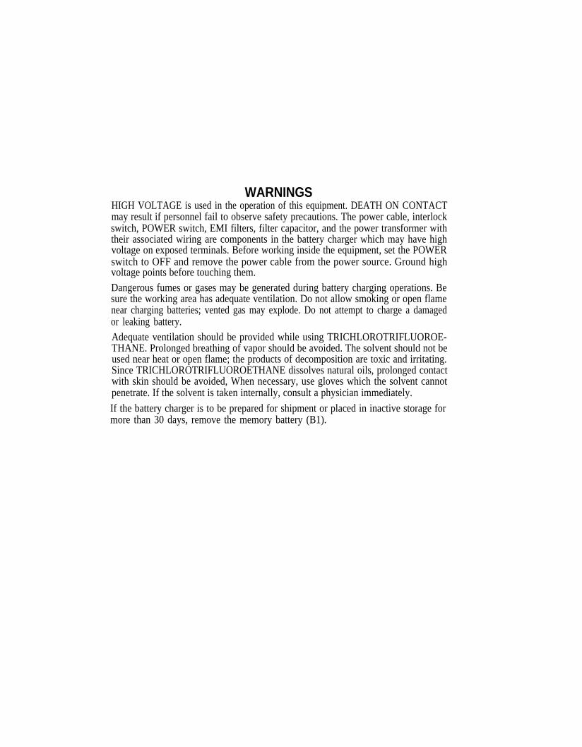
WARNINGSHIGH VOLTAGE is used in the operation of this equipment. DEATH ON CONTACTmay result if personnel fail to observe safety precautions. The power cable, interlockswitch, POWER switch, EMI filters, filter capacitor, and the power transformer withtheir associated wiring are components in the battery charger which may have highvoltage on exposed terminals. Before working inside the equipment, set the POWERswitch to OFF and remove the power cable from the power source. Ground highvoltage points before touching them.Dangerous fumes or gases may be generated during battery charging operations. Besure the working area has adequate ventilation. Do not allow smoking or open flamenear charging batteries; vented gas may explode. Do not attempt to charge a damagedor leaking battery.Adequate ventilation should be provided while using TRICHLOROTRIFLUOROE-THANE. Prolonged breathing of vapor should be avoided. The solvent should not beused near heat or open flame; the products of decomposition are toxic and irritating.Since TRICHLOROTRIFLUOROETHANE dissolves natural oils, prolonged contactwith skin should be avoided, When necessary, use gloves which the solvent cannotpenetrate. If the solvent is taken internally, consult a physician immediately.
If the battery charger is to be prepared for shipment or placed in inactive storage formore than 30 days, remove the memory battery (B1).
SAFETY STEPS TO FOLLOW IF SOMEONEIS THE VICTIM OF ELECTRICAL SHOCK
DO NOT TRY TO PULL OR GRAB THE INDIVIDUAL
IF POSSIBLE, TURN OFF THE ELECTRICAL POWER
IF YOU CANNOT TURN OFF THE ELECTRICALPOWER, PULL, PUSH, OR LIFT THE PERSON TOSAFETY USING A WOODEN POLE OR A ROPE ORSOME OTHER INSULATING MATERIAL
SEND FOR HELP AS SOON AS POSSIBLE
AFTER THE INJURED PERSON IS FREE OFCONTACT WITH THE SOURCE OF ELECTRICALSHOCK, MOVE THE PERSON A SHORT DISTANCEAWAY AND IMMEDIATELY START ARTIFICIALRESUSCITATION
Change 1 A
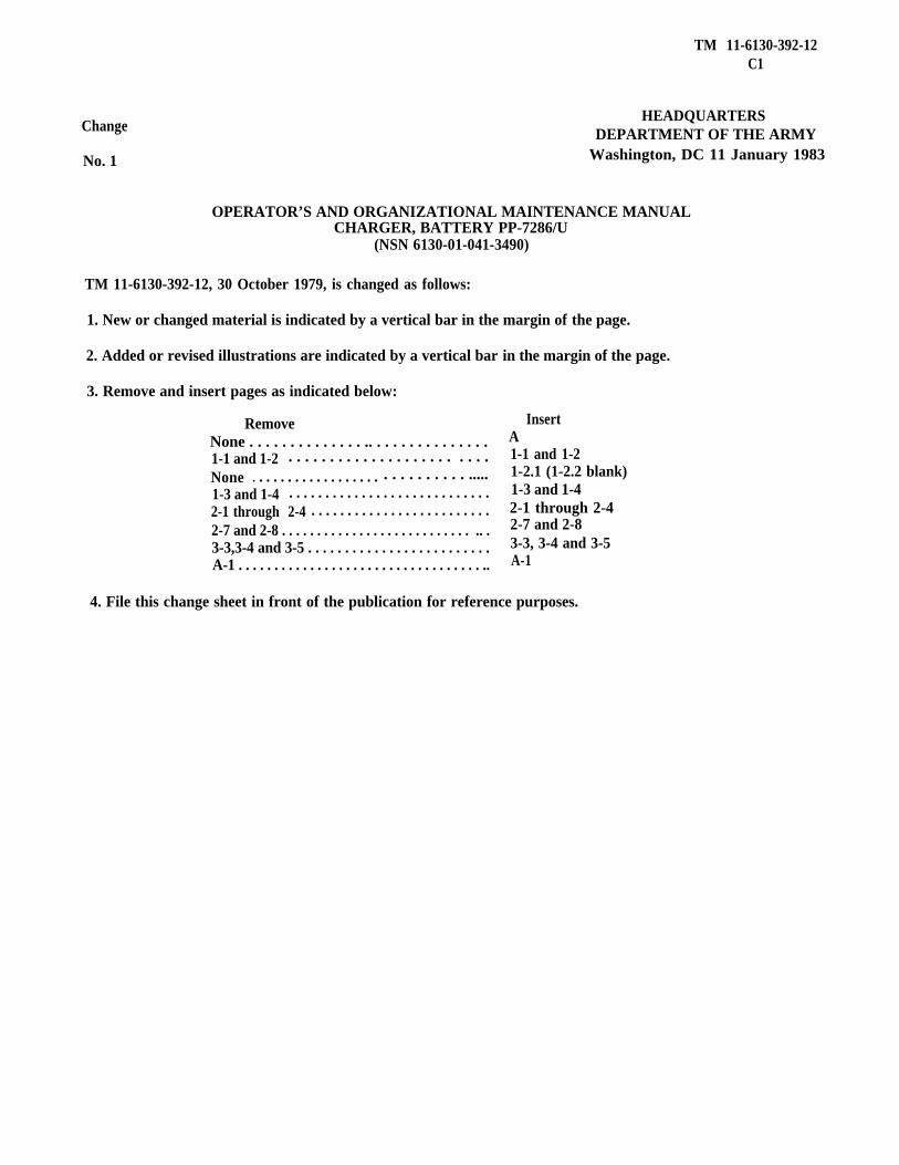
TM 11-6130-392-12C1
Change
No. 1
HEADQUARTERSDEPARTMENT OF THE ARMY
Washington, DC 11 January 1983
OPERATOR’S AND ORGANIZATIONAL MAINTENANCE MANUALCHARGER, BATTERY PP-7286/U
(NSN 6130-01-041-3490)
TM 11-6130-392-12, 30 October 1979, is changed as follows:
1. New or changed material is indicated by a vertical bar in the margin of the page.
2. Added or revised illustrations are indicated by a vertical bar in the margin of the page.
3. Remove and insert pages as indicated below:
RemoveNone . . . . . . . . . . . . . . .. . . . . . . . . . . . . . .1-1 and 1-2 . . . . . . . . . . . . . . . . . . . . . . . .None . . . . . . . . . . . . . . . . . . . . . . . . . . . . .....1-3 and 1-4 . . . . . . . . . . . . . . . . . . . . . . . . . . . .2-1 through 2-4 . . . . . . . . . . . . . . . . . . . . . . . . .2-7 and 2-8 . . . . . . . . . . . . . . . . . . . . . . . . . . . .. .3-3,3-4 and 3-5 . . . . . . . . . . . . . . . . . . . . . . . . .A-1 . . . . . . . . . . . . . . . . . . . . . . . . . . . . . . . . . . ..
InsertA1-1 and 1-21-2.1 (1-2.2 blank)1-3 and 1-42-1 through 2-42-7 and 2-83-3, 3-4 and 3-5A-1
4. File this change sheet in front of the publication for reference purposes.
By Order of the Secretary of the Army:
E. C. MEYERGeneral United States Army
Chief of StaffOfficial:ROBERT M. JOYCE
Major General United States ArmyThee Adjutant General
DISTRIBUTION
To be distributed in accordance with Special MaiIing List.

TECHNICAL MANUAL
No. 11-6130-392-12
OPERATOR’S AND ORGANIZATIONAL MAINTENANCEFOR
CHARGER, BATTERY PP-7286/U
TM 11-6130-392-12
HEADQUARTERDEPARTMENT OF THE ARMY
WASHINGTON, DC 30 October 1979
MANUAL
(NSN 6130-01-041-3490)
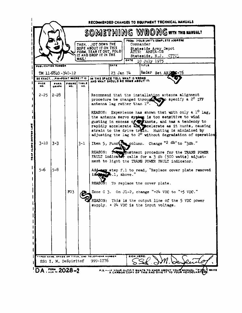
REPORTING ERRORSAND
RECOMMENDING IMPROVEMENTSYou can help improve this manual. If you find any mistakes or if you know of a way to improve the
procedures, please let us know. Mail you letter, DA Form 2028 (Recommended Changes to Publications andBlank Forms), or DA Form 2028-2 located in back of this manual direct to Commander, U.S. Army Com-munications and Electronics Materiel Readiness Command, ATTN: DRSEL-ME-MQ, Fort Monmouth, NJ07703. A reply will be furnished to you.
Paragraph Page
CHAPTERSECTION
1-11-21-31-41-51-6
1-71-81-9
1-101-11
SECTION
CHAPTERSECTION
2-12-22-3
2-42-5
2-62-72-8
2-92-10
C H A P T E R
SECTION
SECTION
1.I.
II.
2.I.
II.
III.
IV.
3.I.
II.
III.
IV.
INTRODUCTIONGeneralScopeIndexes of PublicationsForms and RecordsDestruction of Army MaterielAdministrative StorageReporting Equipment Improvement Recommendations (EIR)Description and DataPurpose and UseDescriptionTabulated DataItems Comprising an Operable EquipmentAdditional Equipment RequiredOPERATING INSTRUCTIONSService Upon Receipt and InstallationSite RequirementsChecking Unpacked EquiprnentInstallationControls and IndicatorsDamage from Improper SettingOperator Controls and IndicatorsOperating Under Usual ConditionsPreliminary Control SettingsOperating ProceduresShutdown ProocedureOperating Under Unusual ConditionsWeather ConditionsUnusual ConditionsOPERATOR/CREW AND ORGANIZATIONAL MAINTENANCE INSTRUCTIONSTools, Equipment, and LubricationTools and EquipmentLubricationPreventive Maintenance Checks and ServicesGeneralOperator/Crew Preventive Maintenance Checks and ServicesPreventive Maintenance Checks and ServicesOperator/Crew MaintenanceTroubleshootingRemoval and Installation
1-11-21-31-31-31-3
1-31-31-41-51-5
2-12-12-1
2-12-1
2-42-42-8
2-82-8
3-13-1
3-1
3-2
3-23-3
i
3-13-2
3-3
3-4
3-53-6
TM 11-6130-392-12
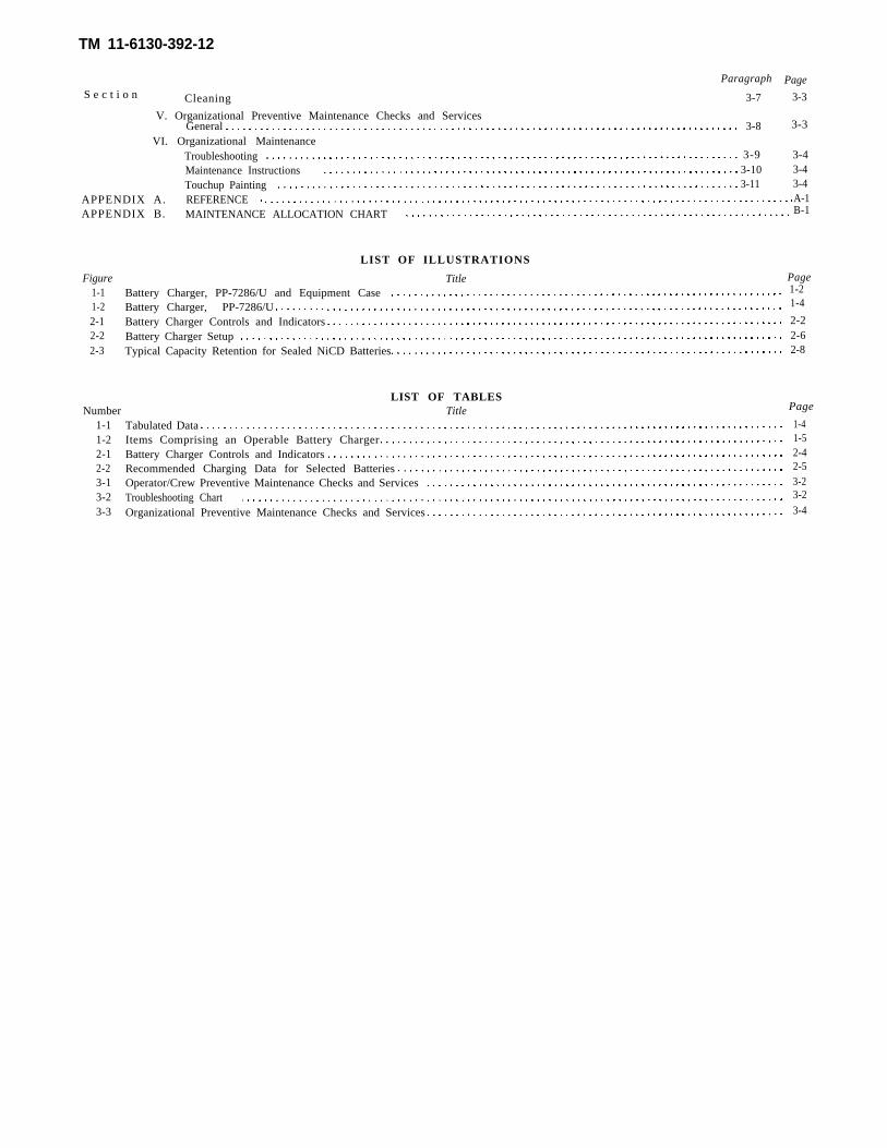
Paragraph PageS e c t i o n Cleaning 3-7
V. Organizational Preventive Maintenance Checks and Services3-8General
VI. Organizational MaintenanceTroubleshooting 3-9Maintenance Instructions 3-10Touchup Painting 3-11
3-3
3-3
3-43-43-4
APPENDIX A. REFERENCEAPPENDIX B. MAINTENANCE ALLOCATION CHART
A-1B-1
Figure1-11-22-12-22-3
LIST OF ILLUSTRATIONS
Title PageBattery Charger, PP-7286/U and Equipment Case 1-2
Battery Charger, PP-7286/U 1-4
Battery Charger Controls and Indicators 2-2Battery Charger Setup 2-6Typical Capacity Retention for Sealed NiCD Batteries 2-8
LIST OF TABLESNumber Title Page
1-11-22-12-23-13-23-3
Tabulated Data 1-4Items Comprising an Operable Battery Charger 1-5
Battery Charger Controls and Indicators 2-4Recommended Charging Data for Selected Batteries 2-5
Operator/Crew Preventive Maintenance Checks and Services 3-2Troubleshooting Chart 3-2
Organizational Preventive Maintenance Checks and Services 3-4
TM 11-6130-392-12
CHAPTER 1INTRODUCTION
Section I. GENERAL
1-1. ScopeThis manual contains insturctions for operation andorganizational maintenance of the Battery ChargerPP-7286/U, (fig. l-l). Included are instructions for in-
stalling, operating, amd maintaining the battery charger.Tools, materials, and test equipment required for opera-t i o n a n d m a i n t e n a n c e a r e a l s o l i s t e d .
Also included in this manual are instructions forinstalling, operating, and maintaining the BatteryCharging Tray Assembly MX-10154( )/U (figure1-1.1).
Change 1 1-1
TM 11-6130-392-12
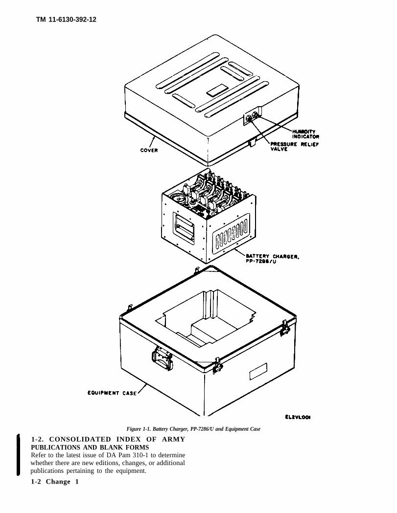
Figure 1-1. Battery Charger, PP-7286/U and Equipment Case
1-2. CONSOLIDATED INDEX OF ARMYPUBLICATIONS AND BLANK FORMSRefer to the latest issue of DA Pam 310-1 to determinewhether there are new editions, changes, or additionalpublications pertaining to the equipment.
1-2 Change 1

TM 11-6130-392-12
Figure 1-1.1. Battery Charging Tray Assembly MX-10154( )/U
Change 1 1-2.1 /(1-2.2 blank)

1-3. Maintenance Forms, Records and Reportsa. Reports of Maintenance and Unsatisfactory
Equipment. Department of the Army forms and pro-cedures used for equipment maintenance will be thoseprescribed by TM 38-750. The Army MaintenanceManagement System (TAMMS).
b. Report of Packaging and Handling Deficien-cies. Fill out and forward SF 364 (Report of Discrepan-cy (ROD)) as prescribed in AR 735-1l-2/DLAR 4140.55NAVMATINST 4355.73/AFR 400-54/MCO 4430.3E.
c. Discrepancy in Shipment Report (DISREP)(SF 361 ). Fill out and forward Discrepancy in ShipmentReport (DISREP) (SF 361) as prescribed in AR 55-38/NAVSUPINST 4610 .33B/AFR 75-18/MCOP4610.19C/DLAR 4500.15.
1-4. Destruction of Army MaterielDestruction of Army Materiel to prevent enemy use
shall
1-5.
TM 11-6130-392-12
be as prescribed in TM 750-244-2.
Administrative StorageProcedures, forms and records, and inspections re-quired during administrative storage of equipmentwill be those prescribed by TM 740-90-1.
1-6. Reporting Equipment ImprovementRecommendations (EIR)
If your Battery Charger PP-7286/U needs improve-ment, let us know. Send us an EIR. You, the user,are the only one who can tell us what you don’tlike about your equipment. Let us know why youdon’t like the design. Tell us why a procedure ishard to perform. Put it on an SF 368 (QualityDeficiency Report). Mail it to Commander, USArmy Communications -Electronics Commandand Fort Monmouth, ATTN: DRSEL-ME-MP.Fort Monmouth, NJ 07703. We’ll send you a reply.
Section II. DESCRIPTION AND DATA
1-7. Purpose and UseThe PP-7286/U is a portable self-contained batterycharger designed to charge sealed ,nickel-cadmium(Ni-Cd) batteries such as: the BB-516/U used in theLaser Infrared Obscuration Set AN/GVS-5 herein-after referred to as LR; the BB-557( )/U (DigitalMessage Device AN/PSG-2); the BB-699( )/PAQ-l(Target Designator Laser); and the BB-704( )/U(GLLD). It will charge any 6,12,24 or 28 voltsealed Ni-Cd battery capable of either fitting in thefive battery holders on the front panel (pressurecontacts adjustable from 0.25 to 4.0 inches) or beingattached to cables connected to the five sets of plug-in-connectors (jacks) located beneath the batteryholders. The MX-10154( )/U is used in conjunctionwith the PP-7286/U. The tray can accommodate upto six sealed nickel-cadmium (Ni-Cd) batteriesBB-503/TAS.1-8. DescriptionThe batter charger (figure 1-2) consists of an ac todc converter and five 15 to 700 mA constant currentcharging channels. The battery charger operatesfrom either 115 vac or 230 vac, 47 to 400 Hz singlephase power source. Each channel is provided with
an adjustable pressure contact battery holder foraccepting sealed nickel-cadmium batteries, such asthe BB-516/U battery, used in the LR. Each chan-nel is also provided with remote battery jacks foruse with external cables or clip leads. A CHANNELSELECT switch, VOLTAGE TEST SELECT switch,VOLTAGE TEST/CHG mA switch and a panelmeter are provided for setting individual channelcharge current and for monitoring individual bat-tery voltage. The individual channel currents areadjustable by means of FINE ADJ screws and aCURRENT SET locking toggle switch. The batterycharging tray is made of Lexan plastic material andfurnishes a means of charging one through sixBB-503/TAS batteries from a constant currentsource supplied by the charger. The tray is provi-ded with five single pole, single throw, normallyclosed, five ampere rating pushbutton switches andsix sockets. A cable assembly, terminated at oneend in a “Y” configuration, has a red banana plugat the positive terminal and a black banana plug atthe negative terminal. Two cleats, integral to thecover, serve to secure the cable when it is not inuse.
Change 1 1-3
TM 11-6130-392-12
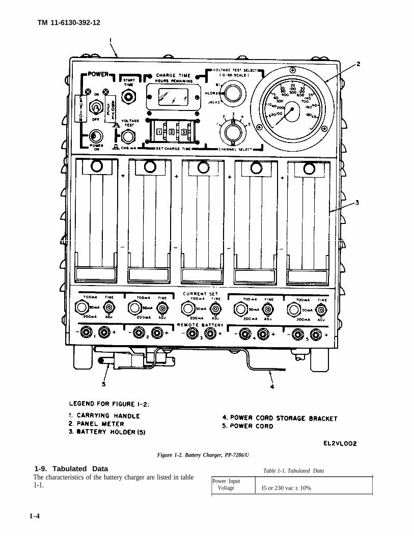
Figure 1-2. Battery Charger, PP-7286/U
1-9. Tabulated Data Table 1-1. Tabulated DataThe characteristics of the battery charger are listed in table1-1.
Power InputVoltage l5 or 230 vac ± 10%
1-4
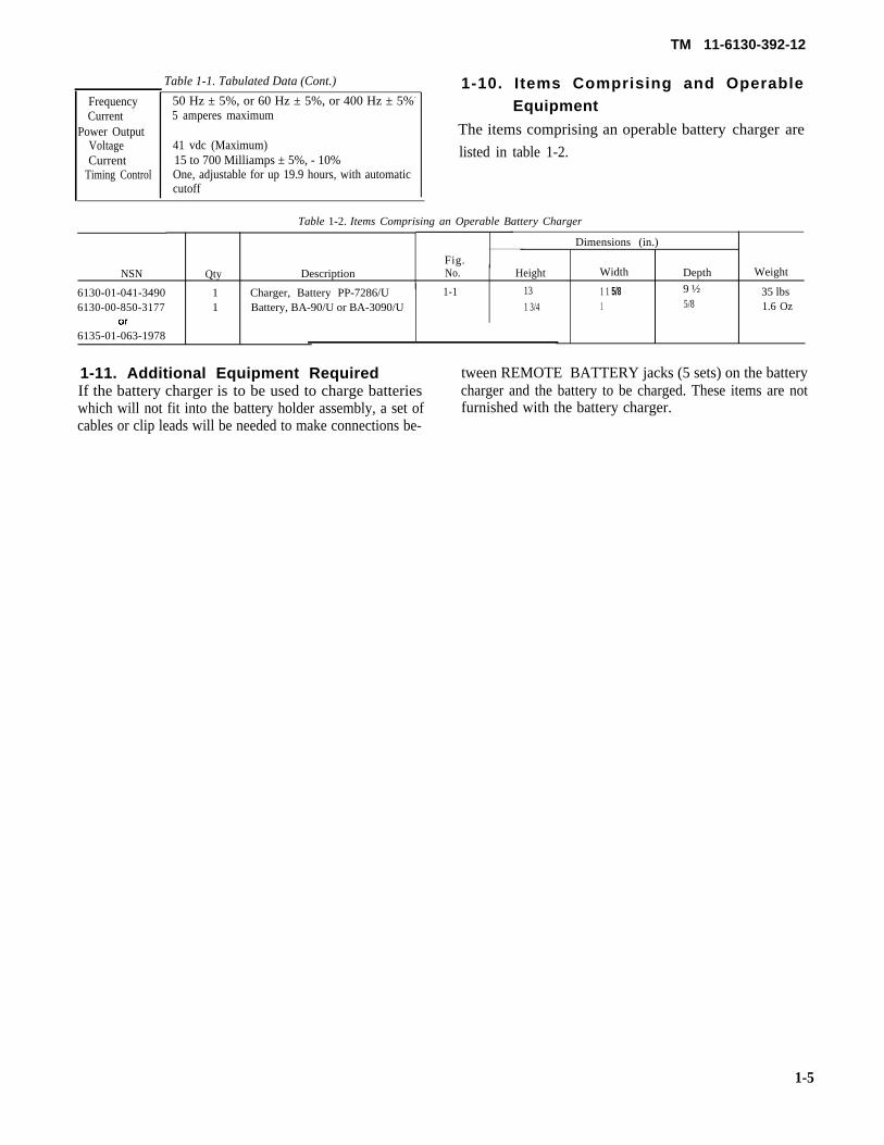
Table 1-1. Tabulated Data (Cont.)
FrequencyCurrent
Power OutputVoltageCurrent
Timing Control
50 Hz ± 5%, or 60 Hz ± 5%, or 400 Hz ± 5%-
5 amperes maximum
41 vdc (Maximum)15 to 700 Milliamps ± 5%, - 10%One, adjustable for up 19.9 hours, with automaticcutoff
TM 11-6130-392-12
1-10. Items Comprising and OperableEquipment
The items comprising an operable battery charger are
listed in table 1-2.
Table 1-2. Items Comprising an Operable Battery Charger
Dimensions (in.)
Fig. NSN Qty Description No. Height Width Depth Weight
6130-01-041-3490 1 Charger, Battery PP-7286/U 1-1 13 1 1 5/8 9 ½ 35 lbs6130-00-850-3177 1 Battery, BA-90/U or BA-3090/U 1 3/4 1 5/8 1.6 Oz
6135-01-063-1978
1-11. Additional Equipment Required tween REMOTE BATTERY jacks (5 sets) on the batteryIf the battery charger is to be used to charge batteries charger and the battery to be charged. These items are notwhich will not fit into the battery holder assembly, a set of furnished with the battery charger.cables or clip leads will be needed to make connections be-
1-5
TM 11-6130-392-12
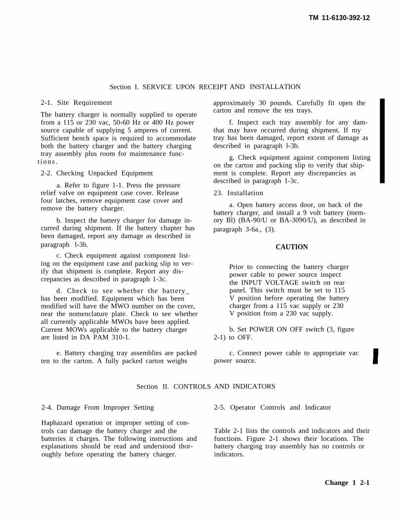
Section I. SERVICE UPON RECEIPT AND INSTALLATION
2-1. Site Requirement
The battery charger is normally supplied to operatefrom a 115 or 230 vac, 50-60 Hz or 400 Hz powersource capable of supplying 5 amperes of current.Sufficient bench space is required to accommodateboth the battery charger and the battery chargingtray assembly plus room for maintenance func-
t i ons .
2-2. Checking Unpacked Equipment
a. Refer to figure 1-1. Press the pressurerelief valve on equipment case cover. Releasefour latches, remove equipment case cover andremove the battery charger.
b. Inspect the battery charger for damage in-curred during shipment. If the battery chapter hasbeen damaged, report any damage as described inparagraph l-3b.
c. Check equipment against component list-ing on the equipment case and packing slip to ver-ify that shipment is complete. Report any dis-crepancies as described in paragraph 1-3c.
d. Check to see whether the battery_has been modified. Equipment which has beenmodified will have the MWO number on the cover,near the nomenclature plate. Check to see whetherall currently applicable MWOs have been applied.Current MOWs applicable to the battery chargerare listed in DA PAM 310-1.
e. Battery charging tray assemblies are packedten to the carton. A fully packed carton weighs
Section II. CONTROLS
2-4. Damage From Improper Setting
Haphazard operation or improper setting of con-trols can damage the battery charger and thebatteries it charges. The following instructions andexplanations should be read and understood thor-oughly before operating the battery charger.
approximately 30 pounds. Carefully fit open thecarton and remove the ten trays.
f. Inspect each tray assembly for any dam-that may have occurred during shipment. If mytray has been damaged, report extent of damage asdescribed in paragraph l-3b.
g. Check equipment against component listingon the carton and packing slip to verify that ship-ment is complete. Report any discrepancies asdescribed in paragraph 1-3c.
23. Installation
a. Open battery access door, on back of thebattery charger, and install a 9 volt battery (mem-ory Bl) (BA-90/U or BA-3090/U), as described inparagraph 3-6a., (3).
CAUTION
Prior to connecting the battery chargerpower cable to power source inspectthe INPUT VOLTAGE switch on rearpanel. This switch must be set to 115V position before operating the batterycharger from a 115 vac supply or 230V position from a 230 vac supply.
b. Set POWER ON OFF switch (3, figure2-1) to OFF.
c. Connect power cable to appropriate vacpower source.
AND INDICATORS
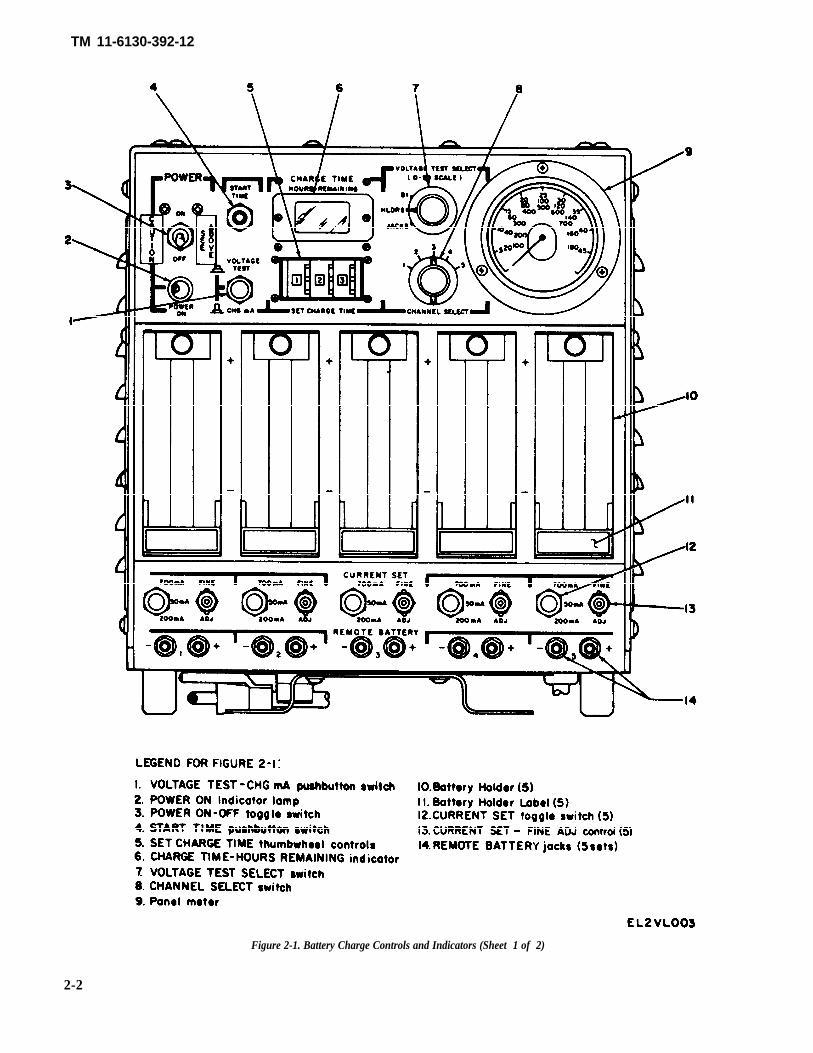
2-5. Operator Controls and Indicator
Table 2-1 lists the controls and indicators and theirfunctions. Figure 2-1 shows their locations. Thebattery charging tray assembly has no controls orindicators.
Change 1 2-1
TM 11-6130-392-12
Figure 2-1. Battery Charge Controls and Indicators (Sheet 1 of 2)
2-2
TM 11-6130-392-12
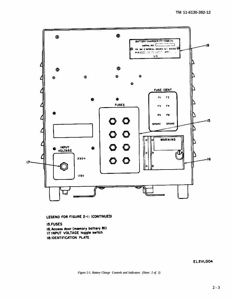
Figure 2-1. Battery Charge Controls and Indicators (Sheet 2 of 2)
2 - 3
TM 11-6130-392-12
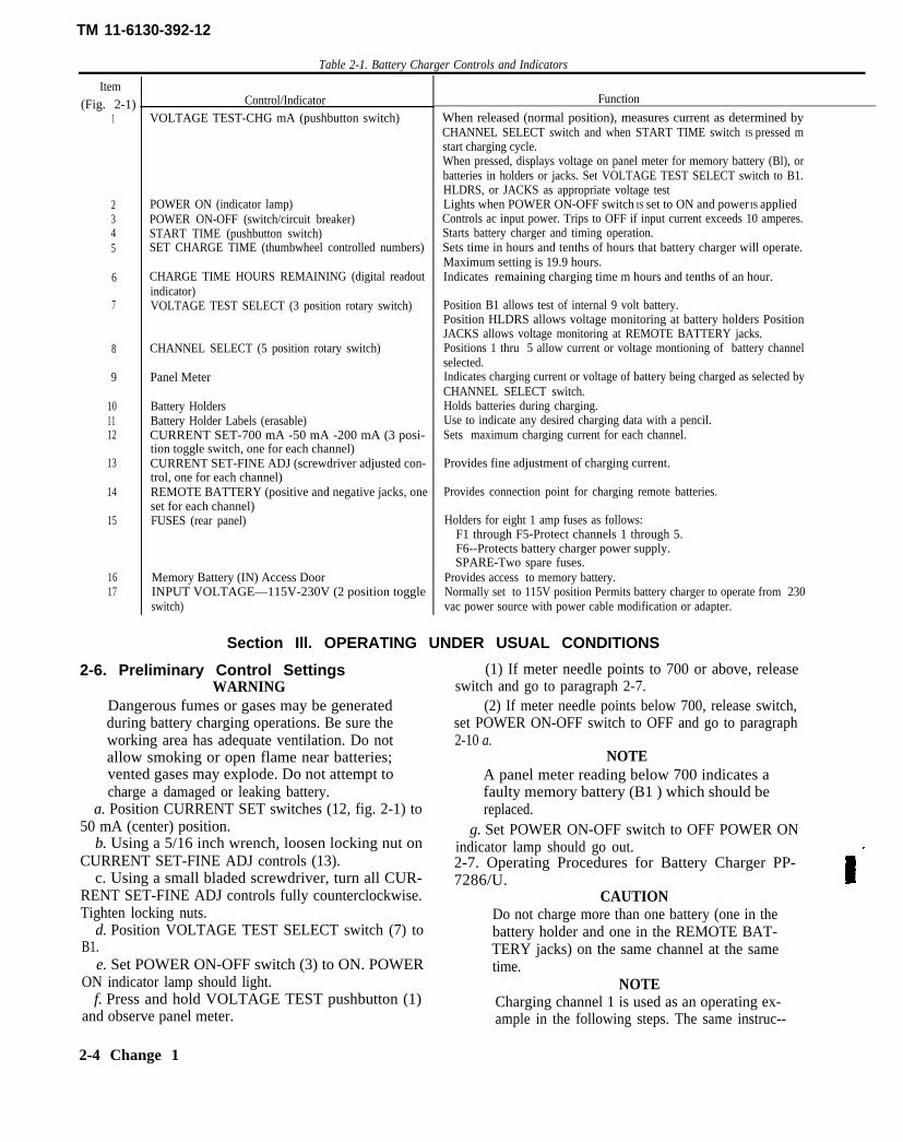
Table 2-1. Battery Charger Controls and Indicators
Item(Fig. 2-1)
1
2345
6
7
8
9
101112
13
14
15
1617
Control/IndicatorVOLTAGE TEST-CHG mA (pushbutton switch)
POWER ON (indicator lamp)POWER ON-OFF (switch/circuit breaker)START TIME (pushbutton switch)SET CHARGE TIME (thumbwheel controlled numbers)
CHARGE TIME HOURS REMAINING (digital readoutindicator)VOLTAGE TEST SELECT (3 position rotary switch)
CHANNEL SELECT (5 position rotary switch)
Panel Meter
Battery HoldersBattery Holder Labels (erasable)CURRENT SET-700 mA -50 mA -200 mA (3 posi-tion toggle switch, one for each channel)CURRENT SET-FINE ADJ (screwdriver adjusted con-trol, one for each channel)REMOTE BATTERY (positive and negative jacks, oneset for each channel)FUSES (rear panel)
Memory Battery (IN) Access DoorINPUT VOLTAGE—115V-230V (2 position toggleswitch)
Function
When released (normal position), measures current as determined byCHANNEL SELECT switch and when START TIME switch IS pressed mstart charging cycle.When pressed, displays voltage on panel meter for memory battery (Bl), orbatteries in holders or jacks. Set VOLTAGE TEST SELECT switch to B1.HLDRS, or JACKS as appropriate voltage testLights when POWER ON-OFF switch IS set to ON and power IS appliedControls ac input power. Trips to OFF if input current exceeds 10 amperes.Starts battery charger and timing operation.Sets time in hours and tenths of hours that battery charger will operate.Maximum setting is 19.9 hours.Indicates remaining charging time m hours and tenths of an hour.
Position B1 allows test of internal 9 volt battery.Position HLDRS allows voltage monitoring at battery holders PositionJACKS allows voltage monitoring at REMOTE BATTERY jacks.Positions 1 thru 5 allow current or voltage montioning of battery channelselected.Indicates charging current or voltage of battery being charged as selected byCHANNEL SELECT switch.Holds batteries during charging.Use to indicate any desired charging data with a pencil.Sets maximum charging current for each channel.
Provides fine adjustment of charging current.
Provides connection point for charging remote batteries.
Holders for eight 1 amp fuses as follows:F1 through F5-Protect channels 1 through 5.F6--Protects battery charger power supply.SPARE-Two spare fuses.
Provides access to memory battery.Normally set to 115V position Permits battery charger to operate from 230vac power source with power cable modification or adapter.
Section Ill. OPERATING UNDER USUAL CONDITIONS
2-6. Preliminary Control SettingsWARNING
Dangerous fumes or gases may be generatedduring battery charging operations. Be sure theworking area has adequate ventilation. Do notallow smoking or open flame near batteries;vented gases may explode. Do not attempt tocharge a damaged or leaking battery.
a. Position CURRENT SET switches (12, fig. 2-1) to50 mA (center) position.
b. Using a 5/16 inch wrench, loosen locking nut onCURRENT SET-FINE ADJ controls (13).
c. Using a small bladed screwdriver, turn all CUR-RENT SET-FINE ADJ controls fully counterclockwise.Tighten locking nuts.
d. Position VOLTAGE TEST SELECT switch (7) toB1.
e. Set POWER ON-OFF switch (3) to ON. POWERON indicator lamp should light.
f. Press and hold VOLTAGE TEST pushbutton (1)and observe panel meter.
2-4 Change 1
(1) If meter needle points to 700 or above, releaseswitch and go to paragraph 2-7.
(2) If meter needle points below 700, release switch,set POWER ON-OFF switch to OFF and go to paragraph2-10 a.
NOTEA panel meter reading below 700 indicates afaulty memory battery (B1 ) which should bereplaced.
g. Set POWER ON-OFF switch to OFF POWER ONindicator lamp should go out.2-7. Operating Procedures for Battery Charger PP-7286/U.
CAUTIONDo not charge more than one battery (one in thebattery holder and one in the REMOTE BAT-TERY jacks) on the same channel at the sametime.
NOTECharging channel 1 is used as an operating ex-ample in the following steps. The same instruc--
TM 11-6130-392-12
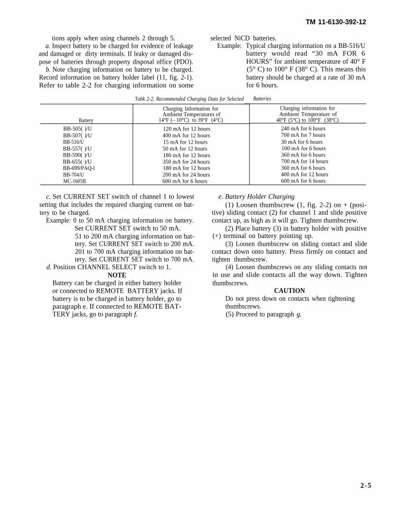
tions apply when using channels 2 through 5. selected NiCD batteries.a. Inspect battery to be charged for evidence of leakage Example:
and damaged or dirty terminals. If leaky or damaged dis-pose of batteries through property disposal office (PDO).
b. Note charging information on battery to be charged.Record information on battery holder label (11, fig. 2-1).Refer to table 2-2 for charging information on some
Tabk 2-2. Recommended Charging Data for Selected
Charging Information forAmbient Temperatures of
Battery 14°F (– 10°C) to 39°F (4°C)
BB-505( )/UBB-507( )/UBB-516/UBB-557( )/UBB-590( )/UBB-655( )/UBB-699/PAQ-lBB-704/UMC-1605B
120 mA for 12 hours400 mA for 12 hours15 mA for 12 hours50 mA for 12 hours180 mA for 12 hours350 mA for 24 hours180 mA for 12 hours200 mA for 24 hours600 mA for 6 hours
Typical charging information on a BB-516/Ubattery would read “30 mA FOR 6HOURS” for ambient temperature of 40° F(5° C) to 100° F (38° C). This means thisbattery should be charged at a rate of 30 mAfor 6 hours.
Batteries
Charging information forAmbient Temperature of
40°F (5°C) to 100°F (38°C)
240 mA for 6 hours700 mA for 7 hours30 mA for 6 hours100 mA for 6 hours360 mA for 6 hours700 mA for 14 hours360 mA for 6 hours400 mA for 12 hours600 mA for 6 hours
c. Set CURRENT SET switch of channel 1 to lowestsetting that includes the required charging current on bat-tery to be charged.
Example: 0 to 50 mA charging information on battery.Set CURRENT SET switch to 50 mA.51 to 200 mA charging information on bat-tery. Set CURRENT SET switch to 200 mA.201 to 700 mA charging information on bat-tery. Set CURRENT SET switch to 700 mA.
d. Position CHANNEL SELECT switch to 1.NOTE
Battery can be charged in either battery holderor connected to REMOTE BATTERY jacks. Ifbattery is to be charged in battery holder, go toparagraph e. If connected to REMOTE BAT-TERY jacks, go to paragraph f.
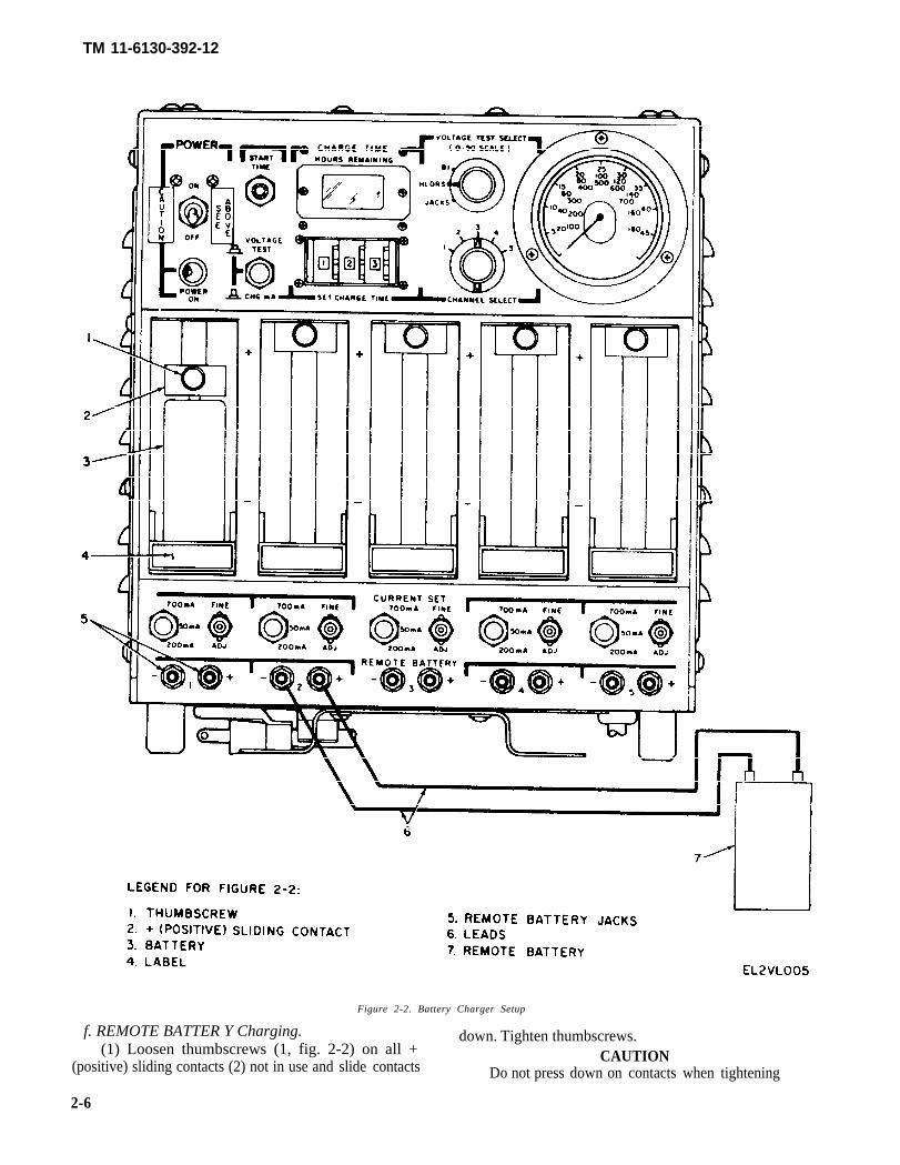
e. Battery Holder Charging(1) Loosen thumbscrew (1, fig. 2-2) on + (posi-
tive) sliding contact (2) for channel 1 and slide positivecontact up, as high as it will go. Tighten thumbscrew.
(2) Place battery (3) in battery holder with positive(+) terminal on battery pointing up.
(3) Loosen thumbscrew on sliding contact and slidecontact down onto battery. Press firmly on contact andtighten thumbscrew.
(4) Loosen thumbscrews on any sliding contacts notin use and slide contacts all the way down. Tightenthumbscrews.
CAUTIONDo not press down on contacts when tighteningthumbscrews.(5) Proceed to paragraph g.
2-5
TM 11-6130-392-12
Figure 2-2. Battery Charger Setup
f. REMOTE BATTER Y Charging. down. Tighten thumbscrews.(1) Loosen thumbscrews (1, fig. 2-2) on all + CAUTION
(positive) sliding contacts (2) not in use and slide contacts Do not press down on contacts when tightening
2-6

thumbscrews.
TM 11-6130-392-12
NOTE
(2) Unscrew REMOTE BATTERY +(Red) and – (Black) jacks (5) for channel 1.
NOTE
The battery charger does not have a setof leads or cables (6) for remote batterycharging. A set of leads or cables will beneeded for remote battery charging.
(3) Connect one lead from positive (+)terminal on battery being charged to red jack onbattery charger. Tighten jack.
(4) Connect the other lead from negative(–) terminal on battery to black jack on batterycharger. Tighten jack.
(5) Tighten all REMOTE BATTERY jacksnot in use.
g. Set thumbwheels on SET CHARGE TIMEcontrol (figure 2-1) to charging time required,
Example: Normally, the batteries in channell through 5will all be same type re-quiring same charging time. If allbatteries, such as BB-516/U, re-quire a charge of 6 hours; setthumbwheels to read 6.0.
If more than one type of battery,each requiring a different chargingtime, is to be charged at the sametime use the shortest time re-quirement (6 hours).
h. Set POWER ON-OFF switch to ON.POWER ON indicator lamp lights.
i. Set CHANNEL SELECT switch to posi-tion 1 and press START TIME switch.
j. Using a 5/16 inch wrench, loosen lockingnut on channel 1 CURRENT SET-FINE ADJcontrol.
k. Using a small bladed screwdriver, slowlyturn CURRENT SET-FINE ADJ control untilneedle on panel meter points to current chargingrate required for battery being charged.
Example: If battery to be charged is a BB-516/U (refer to table 2-2) and theambient temperature is 40° F (5°C)to 100° F (38°C); the needle shouldbe set to 30 mA which is read on0-50 panel meter scale.
When adjusting FINE ADJ controls for otherchannels, set CHANNEL SELECT switch toeach battery channel being adjusted.
l. Tighten locking nut, after each channel isadjusted.
m. Allow battery charger to go through charg-ing time and stop charging automatically whenCHARGE TIME-HOURS REMAINING displayreads O and then extinguishes.
NOTE
If different type batteries, requiring differ-ent charge times, were connected and re-quired additional charging proceed to stepn. If no more charging is required, pro-ceed to paragraph 2-8.
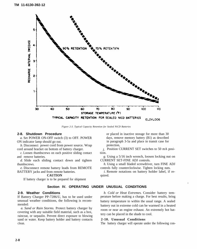
n. Set POWER ON-OFF switch to OFF. Re-move fully charged battery. Figure 2-3 shows theretention rate of a fully charged battery at variousdegrees in Fahrenheit.
o. Set CHARGE TIME control for addedcharge time always using shortest time.
p. Set POWER ON OFF switch to ON. PressSTART TIME pushbutton.
q. Repeat steps m., n., and o. as required, tocomplete charging of remaining batteries.
2-7.1. Operating Procedures for Battery ChargingTray Assembly MX-10154( )/U
a. The battery holder contains six batteryholding compartments. A pushbutton switch ispositioned at the bottom of each of five compart-ments designated SW1 through SW5. The sixthcompartment does not contain a pushbuttonswitch and has no designation.
b. When only one battery is to be charged itmust be placed in the sixth undesignated compart-ment and the battery terminal pressed firmly intothe socket designated J6.
c. Up to six batteries may be charged at thesame time. If less than six batteries, but more thanone are to be charged, one of the batteries must beinserted in the sixth (undersignated) compartment.The remaining batteries to be charged can beplaced randomly in any of the other five desig-nated compartment. Refer to paragraph 2-7fthrough q for the proper remote battery chargingprocedures.
Change 1 2-7
TM 11-6130-392-12
Figure 2-3. Typical Capacity Retention for Sealed NiCD Batteries
2-8. Shutdown Procedurea. Set POWER ON-OFF switch (3) to OFF. POWER
ON indicator lamp should go out.b. Disconnect power cord from power source. Wrap
cord around bracket on bottom of battery charger. j.
or placed in inactive storage for more than 30days, remove memory battery (B1) as describedin paragraph 3-5a and place in transit case forprotection,Position CURRENT SET switches to 50 mA posi-
c. Loosen thumbscrews on each positive sliding contact tion.and remove batteries. g. Using a 5/16 inch wrench, loosen locking nut on
d. Slide each sliding contact down and tighten CURRENT SET-FINE ADJ controls.thumbscrews. h. Using a small bladed screwdriver, turn FINE ADJ
e. Disconnect remote battery leads from REMOTE controls fully counterclockwise. Tighten locking nuts.BATTERY jacks and from remote batteries. i. Remote notations on battery holder label, if re-
CAUTION quired.If battery charger is to be prepared for shipment
Section IV. OPERATING UNDER UNUSUAL CONDITIONS.
2-9. Weather Conditions b. Cold or Heat Extremes. Consider battery tem-If Battery Charger PP-7286/U, has to be used under perature before making a charge. For best results, bringunusual weather conditions, the following is recom- battery temperature to within the usual range. A sealed mended: battery out in extreme cold can be warmed in a heated
a. Sand or Rain Storms. Protect battery charger bycovering with any suitable field material, such as a box,
room or near an engine exhaust. An extremely hot bat-
raincoat, or tarpaulin. Prevent direct exposure to blowing tery can be placed in the shade to cool.
sand or water. Keep battery holder and battery contacts 2-10. Unusual Conditionsclean. The battery charger will operate under the following con-
2-8
TM 11-6130-392-12
ditions:a. No Memory Battery (B1.), or Memory Battery Failed
Test In Paragraph 2-6. The battery charger will not auto-matically hold remaining charging time, if input power islost or power cable is unplugged in error, during thecharging cycle. The battery charger would have to bereset, to restart the charging cycle. Tag battery charger toindicate memory battery has failed or no memory batteryinstalled. Use a clock to monitor charging time when using
battery charger without a memory battery.b. POWER ON Indicator Does Not Light, or No
Replacement Lamp to Install. Follow each step in Operat-ing Procedure, paragraph 2-7. Press START TIMEswitch, if panel meter (M1) shows a voltage or currentreading the battery charger may be used Protect all per-sonnel by tagging equipment on the front with an easy-to-see warning, and operate only after receiving properauthorization.
2-9
TM 11-6130-392-12
CHAPTER 3OPERATOR/CREW AND ORGANIZATIONAL MAINTENANCE INSTRUCTIONS
Section I. TOOLS, EQUIPMENT, AND LUBRICATION
3-1. Tools and Equipment PP-7286/U, are listed in Appendix B, table B-1.There are no special tools or equipment required by the 3-2. Lubricationoperator. Tools and test equipment, used by organiza- There are no lubrication requirements for the batterytional maintenance personnel for the Battery Charger charger.
Section Il. PREVENTIVE MAINTENANCE CHECKS AND SERVICES
3-3. Generala. Operator/Crew preventive maintenance is the
systematic care, servicing, and inspection of equipment toprevent the occurrence of trouble, to reduce downtime,and to maintain the equipment in serviceable condition.To be sure that your battery charger is always ready foryour mission, you must do scheduled PREVENTIVEMAINTENANCE CHECKS AND SERVICES (PMCS) .
(1) BEFORE OPERATION, perform your B PMCSto be sure that your equipment is ready to go.
(2) DURING OPERATION, perform your DPMCS. This should help you spot small troubles beforethey become big problems.
(3) AFTER OPERATION, perform your A PMCS.This should help you keep your equipment in top shape.
(4) WEEKLY AND MONTHLY PMCS are impor-tant checks you make to keep serious problems from sud-denly happening. Perform WEEKLY as well as BEFOREOPERATION PMCS if:
(a) You are the assigned operator and have notoperated the item since the last WEEKLY.
(b) You are operating the item for the first time.(5) When an item of equipment is reinstalled after
removal for any reason, perform the necessary B PMCS,paragraph 3-4, to be sure the item meets the operationalcriteria.
(6) Use the ITEM NO. column in the PMCS table toget the number to be used in the TM ITEM NO. columnon DA Form 2404 (Equipment Inspection and Mainte-nance Worksheet) when you fill out the form.
b. Organizational preventive maintenance proceduresare designed to help maintain equipment in serviceablecondition. They include what items should be checkedand how to check them. These checks and services de-scribed in paragraph 3-8, outline inspections that are to bemade at specific (W) weekly, (M) monthly, (Q) quar-terly, (S) semiannually and (A) annual intervals.
c. Routine checks like CLEANING, DUSTING,WASHING, CHECKING FOR FRAYED CABLES,STOWING ITEMS NOT IN USE, COVERINGUNUSED RECEPTACLES AND CHECKING FORLOOSE NUTS AND BOLTS are not listed as PMCSchecks. They are things that you should do anytime yousee they must be done. If you find a routine check like one
of those listed, in your PMCS, it was listed because otheroperators reported problems with this item.
WHEN YOU ARE DOING ANY PMCS ORROUTINE CHECKS, KEEP IN MIND THEWARNINGS AND CAUTIONS.
WARNINGSCompressed air is dangerous and can cause
serious bodily harm if protective means ormethods are not observed to prevent a chip orparticle (of whatever size) from being blowninto the eyes or unbroken skin of the operator orother personnel. Compressd air shall not beused for cleaning purposes except wherereduced to less than 30 psi and then only witheffective chip guarding and personnel protectiveequipment. Do not use compressed air to dryparts when trichlorotrifluoroethane has beenused.
Adequate ventilation should be providedwhile using TRICHLOROTRIFLUOROE-THANE. Prolonged breathing of vapor shouldbe avoided. The solvent should not be used nearheat or open flame; the products of decomposi-tion are toxic and irritating. Since TRICHLO-ROTRIFLUOROETHANE dissolves naturaloils, prolonged contact with skin should beavoided. When necessary, use gloves which thesolvent cannot penetrate. If the solvent is takeninternally, consult a physician immediately.
NOTEThe PROCEDURES column in your PMCScharts instructs you how to perform the requiredchecks and services. Carefully follow these in-structions and if tools are needed or the chart in-structions tell you, get organizational mainte-nance to do the necessary work. If your equip-ment must be in operation all the time, checkthose items that can be checked and servicedwithout disturbing operation. Make the com-plete checks and services when the equipmentcan be shut down.
3-1
TM 11-6130-392-12
d. Deficiencies that cannot be corrected must be re- Records and reports of preventive maintenance must beported to higher category maintenance personnel. made in accordance with procedures given in TM 38-750.
Section III. OPERATOR/CREW PREVENTIVE MAINTENANCE CHECKS AND SERVICES
3-4. Preventive Maintenance Checks andServices
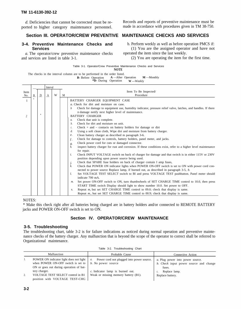
a. The operator/crew preventive maintenance checksand services are listed in table 3-1.
b. Perform weekly as well as before operation PMCS if:(1) You are the assigned operator and have not
operated the item since the last weekly.(2) You are operating the item for the first time.
Table 3-1. Operator/Crew Preventive Maintenance Checks and ServicesNOTE
The checks in the interval column are to be performed in the order listed.
ItemNo.
1
2
B- Before Operation A —After Operation M —Monthly*D- During Operation W —Weekly
—
B—*
D—
*
Interval
A— W MItem To Be Inspected/
Procedure
BATTERY CHARGER EQUIPMENT CASEa. Check for dirt and moisture on case.b Check for damage to equipment use, humidity indicator, pressure relief valve, latches, and handles. If there
IS damage notify next higher level of maintenance.BATTERY CHARGERa.b.c.d.e.
f .g.h.
i.
j.k.
l.
m.
n.
Check that unit is complete.Check for dirt and moisture on unit.Check + and – contacts on battery holders for damage or dirtUsing a soft clean cloth, Wipe dirt and moisture from battery charger.Clean battery charger as described m paragraph 3-6.Check for damage to controls, battery holders, panel meter, and jacks.Check power cord for cuts or damaged connector.inspect battery charger for rust and corrosion. If these conditions exist, refer to a higher level maintenancefor repair.Check INPUT VOLTAGE switch on back of charger for damage and that switch is in either 115V or 230V position depending upon power source being used.Check that SPARE fuse holders on back of charger contain I amp fuses,Check that POWER ON indicator lights when POWER ON-OFF switch is set to ON with power cord con-nected to power source Replace lamp, if burned out, as described in paragraph 3-5, b.Set VOLTAGE TEST SELECT switch to Bl and press VOLTAGE TEST pushbutton. Panel meter shouldindicate 700 mA.Set power ON-OFF switch to ON, turn thumbwheels of SET CHARGE TIME control to 10.0, then pressSTART TIME switch Display should light to show number 10.0. Set power to OFF.Repeat m, but set SET CHARGE TIME control to 09.0; check that display is same.Repeat m., but set SET CHARGE TIME control to 00.9; check that display is same.
NOTES:* Make this check right after all batteries being charged are in battery holders and/or connected to REMOTE BATTERYjacks and POWER ON-OFF switch is set to ON.
Section IV. OPERATOR/CREW MAINTENANCE
3-5. TroubleshootingThe troubleshooting chart, table 3-2 is for failure indications as noticed during normal operation and preventive mainte-nance checks of the battery charger. Any malfunction that is beyond the scope of the operator to correct shall be referred toOrganizational maintenance.
Table 3-2. Troubleshooting Chart
Malfunction Probable Cause Connective Action
1. POWER ON indicator light does not light a. Power cord not plugged into power source. a. Plug power into power source.when POWER ON-OFF switch is set to b. No power source b. Check input power source and changeON or goes out during operation of bat- fuses.tery charger. c. Indicator lamp is burned out. c. Replace lamp.
2. VOLTAGE TEST SELECT control in B1 Weak or missing memory battery (B1). Replace battery.position with VOLTAGE TEST-CHG
3-2
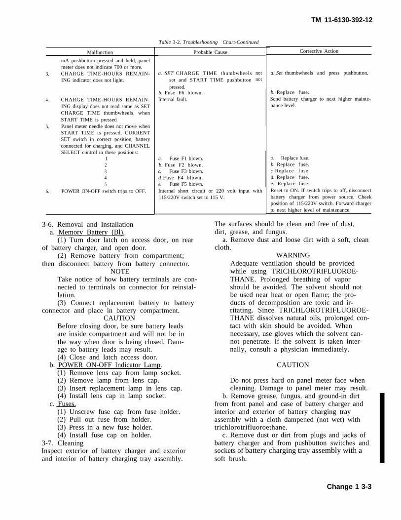
Malfunction
3.
4.
5.
6.
mA pushbutton pressed and held, panelmeter does not indicate 700 or more.CHARGE TIME-HOURS REMAIN-ING indicator does not light.
CHARGE TIME-HOURS REMAIN-ING display does not read same as SETCHARGE TIME thumbwheels, whenSTART TIME is pressedPanel meter needle does not move whenSTART TIME is pressed, CURRENTSET switch in correct position, batteryconnected for charging, and CHANNELSELECT control in these positions:
12345
POWER ON-OFF switch trips to OFF.
3-6. Removal and Installationa. Memory Battery (Bl).
Table 3-2. Troubleshooting Chart-Continued
Probable Cause
a. SET CHARGE TIME thumbwheelsset and START TIME pushbuttonpressed.
b. Fuse F6 blown.Internal fault.
a. Fuse F1 blown.b. Fuse F2 blown.c. Fuse F3 blown.d Fuse F4 blown.e. Fuse F5 blown.
notnot
Internal short circuit or 220 volt input with115/220V switch set to 115 V.
(1) Turn door latch on access door, on rearof battery charger, and open door.
(2) Remove battery from compartment;then disconnect battery from battery connector.
NOTETake notice of how battery terminals are con-nected to terminals on connector for reinstal-lation.(3) Connect replacement battery to battery
connector and place in battery compartment.CAUTION
Before closing door, be sure battery leadsare inside compartment and will not be inthe way when door is being closed. Dam-age to battery leads may result.(4) Close and latch access door.
b. POWER ON-OFF Indicator Lamp.(1) Remove lens cap from lamp socket.(2) Remove lamp from lens cap.(3) Insert replacement lamp in lens cap.(4) Install lens cap in lamp socket.
c. Fuses.(1) Unscrew fuse cap from fuse holder.(2) Pull out fuse from holder.(3) Press in a new fuse holder.(4) Install fuse cap on holder.
3-7. CleaningInspect exterior of battery charger and exteriorand interior of battery charging tray assembly.
TM 11-6130-392-12
Corrective Action
a. Set thumbwheels and press pushbutton.
b. Replace fuse.Send battery charger to next higher mainte-nance level.
a. Replace fuse.b. Replace fuse.c Replace fused. Replace fuse.e., Replace fuse.Reset to ON. If switch trips to off, disconnectbattery charger from power source. Cheekposition of 115/220V switch. Forward chargerto next higher level of maintenance.
The surfaces should be clean and free of dust,dirt, grease, and fungus.
a. Remove dust and loose dirt with a soft, cleancloth.
WARNINGAdequate ventilation should be providedwhile using TRICHLOROTRIFLUOROE-THANE. Prolonged breathing of vaporshould be avoided. The solvent should notbe used near heat or open flame; the pro-ducts of decomposition are toxic and ir-ritating. Since TRICHLOROTRIFLUOROE-THANE dissolves natural oils, prolonged con-tact with skin should be avoided. Whennecessary, use gloves which the solvent can-not penetrate. If the solvent is taken inter-nally, consult a physician immediately.
CAUTION
Do not press hard on panel meter face whencleaning. Damage to panel meter may result.
b. Remove grease, fungus, and ground-in dirtfrom front panel and case of battery charger andinterior and exterior of battery charging trayassembly with a cloth dampened (not wet) withtrichlorotrifluoroethane.
c. Remove dust or dirt from plugs and jacks ofbattery charger and from pushbutton switches andsockets of battery charging tray assembly with asoft brush.
Change 1 3-3
TM 11-6130-392-12
Section V. ORGANIZATIONAL PREVENTIVE MAINTENANCE CHECKS AND SERVICES
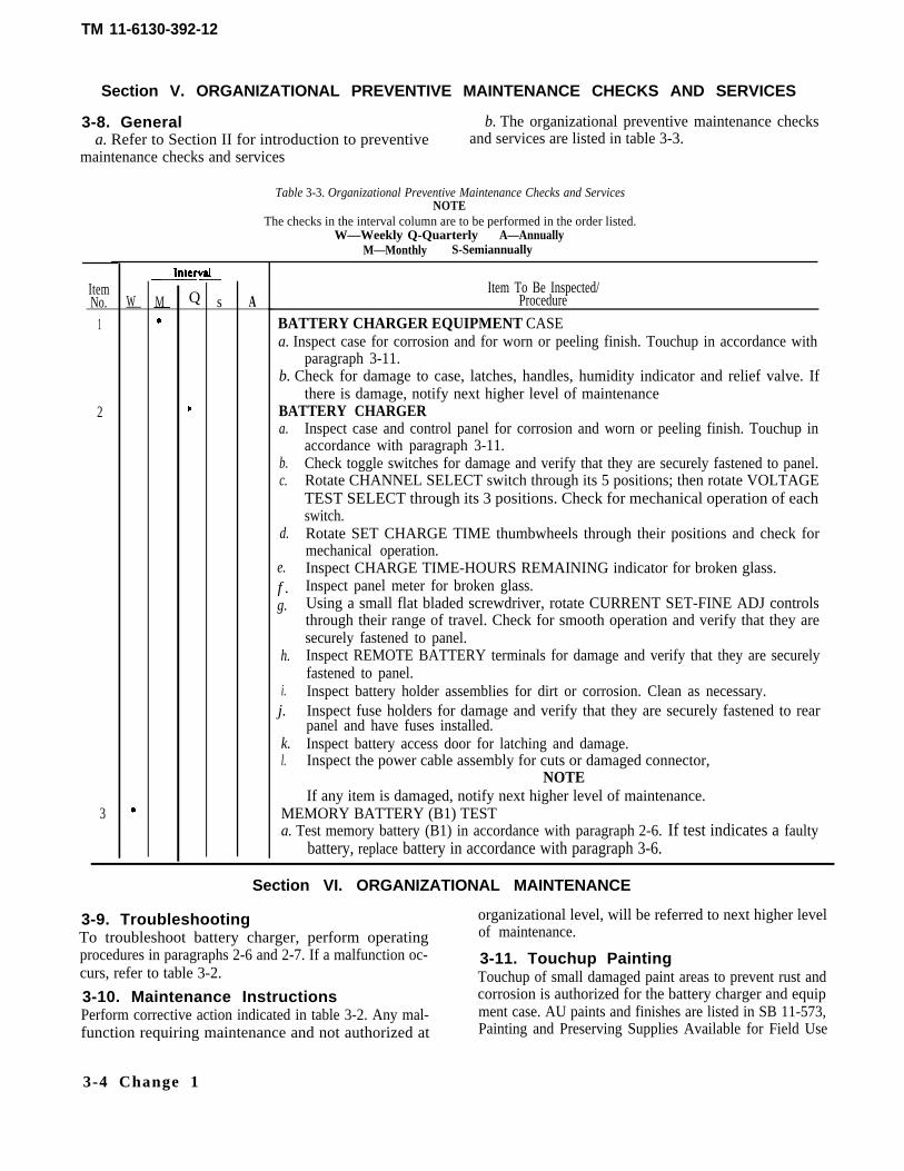
3-8. General b. The organizational preventive maintenance checksa. Refer to Section II for introduction to preventive and services are listed in table 3-3.
maintenance checks and services
Table 3-3. Organizational Preventive Maintenance Checks and ServicesNOTE
The checks in the interval column are to be performed in the order listed.W—Weekly Q-Quarterly A—Annually
M—Monthly S-Semiannually
ItemNo.
1
2
3
W— M— Q s AItem To Be Inspected/
Procedure
BATTERY CHARGER EQUIPMENT CASEa. Inspect case for corrosion and for worn or peeling finish. Touchup in accordance with
paragraph 3-11.b. Check for damage to case, latches, handles, humidity indicator and relief valve. If
there is damage, notify next higher level of maintenanceBATTERY CHARGERa.
b.c.
d.
e.f .g.
h.
i.j.
k.l.
Inspect case and control panel for corrosion and worn or peeling finish. Touchup inaccordance with paragraph 3-11.Check toggle switches for damage and verify that they are securely fastened to panel.Rotate CHANNEL SELECT switch through its 5 positions; then rotate VOLTAGETEST SELECT through its 3 positions. Check for mechanical operation of eachswitch.Rotate SET CHARGE TIME thumbwheels through their positions and check formechanical operation.Inspect CHARGE TIME-HOURS REMAINING indicator for broken glass.Inspect panel meter for broken glass.Using a small flat bladed screwdriver, rotate CURRENT SET-FINE ADJ controlsthrough their range of travel. Check for smooth operation and verify that they aresecurely fastened to panel.Inspect REMOTE BATTERY terminals for damage and verify that they are securelyfastened to panel.Inspect battery holder assemblies for dirt or corrosion. Clean as necessary.Inspect fuse holders for damage and verify that they are securely fastened to rearpanel and have fuses installed.Inspect battery access door for latching and damage.Inspect the power cable assembly for cuts or damaged connector,
NOTEIf any item is damaged, notify next higher level of maintenance.
MEMORY BATTERY (B1) TESTa. Test memory battery (B1) in accordance with paragraph 2-6. If test indicates a faulty
battery, replace battery in accordance with paragraph 3-6.
Section VI. ORGANIZATIONAL MAINTENANCE
3-9. Troubleshooting organizational level, will be referred to next higher level
To troubleshoot battery charger, perform operating of maintenance.
procedures in paragraphs 2-6 and 2-7. If a malfunction oc- 3-11. Touchup Paintingcurs, refer to table 3-2. Touchup of small damaged paint areas to prevent rust and3-10. Maintenance Instructions corrosion is authorized for the battery charger and equipPerform corrective action indicated in table 3-2. Any mal- ment case. AU paints and finishes are listed in SB 11-573,function requiring maintenance and not authorized at Painting and Preserving Supplies Available for Field Use
3-4 Change 1
TM 11-6130-392-12
for Electronics Command Equipment. Refer to TB 43-0118, Field Instructions for Painting and preservingElectronic Equipment Including Camouflage patternPainting of Electrical Equipment Shelters, and AR 746-5,color and marking of Army Materiel.
CAUTION
DO not paint over panel lettering, stenciling,labels warning notices, or glass windows.
a. Equipment Case.(1) Lightly sand touchup area with fine sandpaper,
and wipe with clean cloth.(2) Apply two thin paint coats, color chip 34087
olive drab green, Fed. Std. 595.b. Battery Charger Case.
(1) Lightly sand touchup area with fine sandpaper,and wipe with clean cloth.
(2) Apply primer per MIL-P-23377 and paint perfinish No. P518M of MIL-F-14072.
Change 1 3-5
TM 11-6130-392-12
APPENDIX AREFERENCES
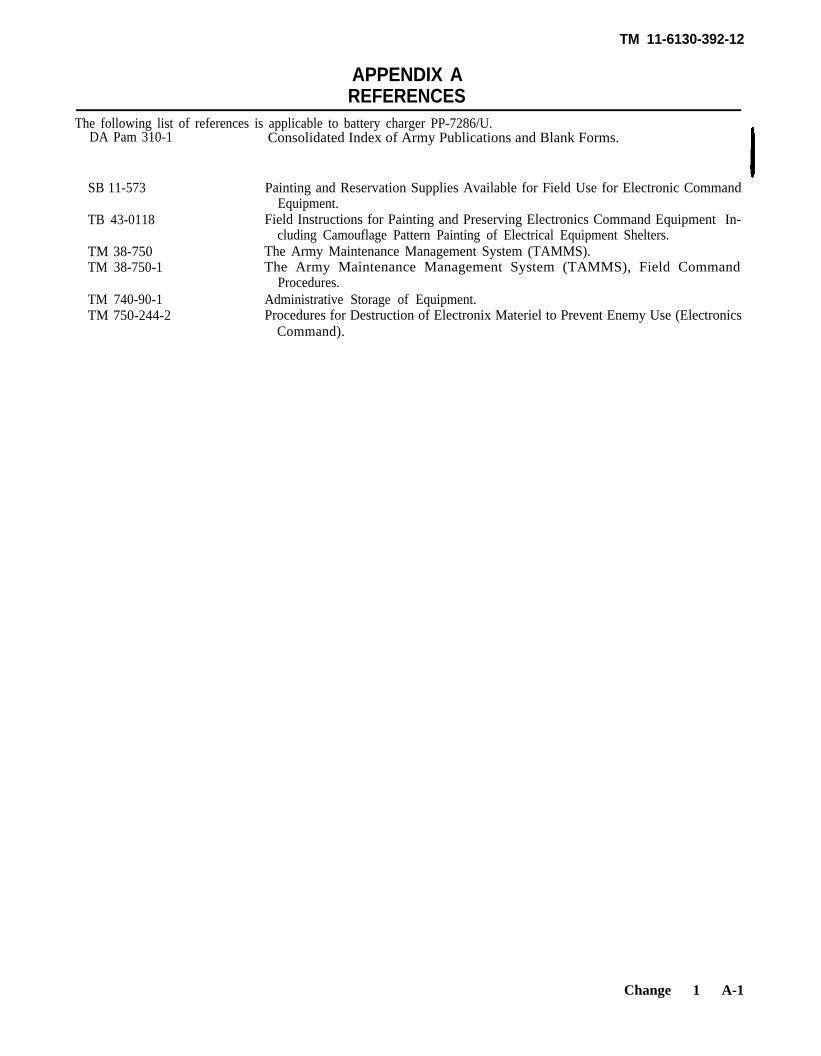
The following list of references is applicable to battery charger PP-7286/U.DA Pam 310-1 Consolidated Index of Army Publications and Blank Forms.
SB 11-573 Painting and Reservation Supplies Available for Field Use for Electronic CommandEquipment.
TB 43-0118 Field Instructions for Painting and Preserving Electronics Command Equipment In-cluding Camouflage Pattern Painting of Electrical Equipment Shelters.
TM 38-750 The Army Maintenance Management System (TAMMS).TM 38-750-1 The Army Maintenance Management System (TAMMS), Field Command
Procedures.TM 740-90-1 Administrative Storage of Equipment.TM 750-244-2 Procedures for Destruction of Electronix Materiel to Prevent Enemy Use (Electronics
Command).
Change 1 A-1
TM 11-6130-392-12
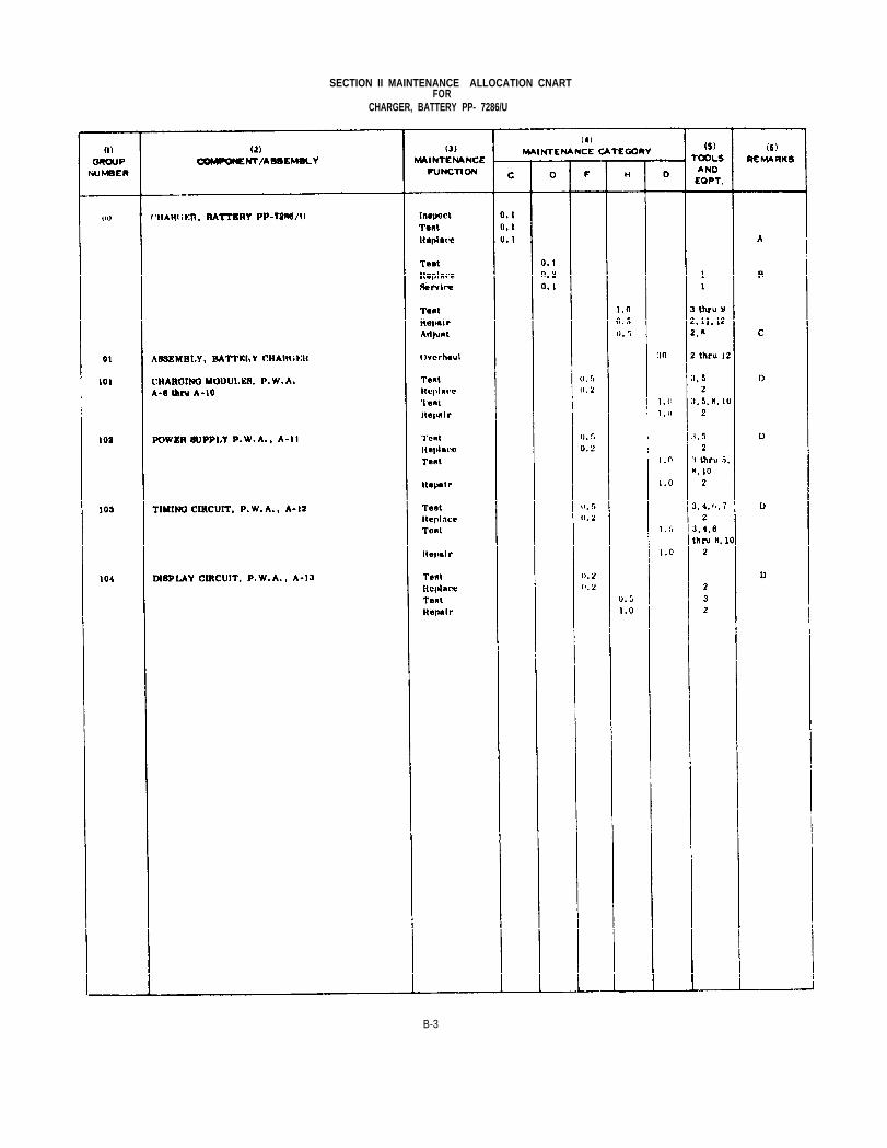
APPENDIX BMAINTENANCE ALLOCATION CHART
Section I. INTRODUCTION
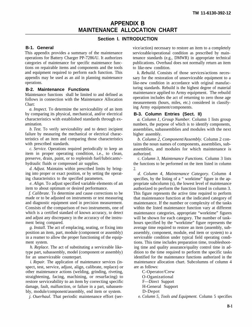
B-1. GeneralThis appendix provides a summary of the maintenanceoperations for Battery Charger PP-7286/U. It authorizescategories of maintenance for specific maintenance func-tions on repairable items and components and the toolsand equipment required to perform each function. Thisappendix may be used as an aid in planning maintenanceoperations.
B-2. Maintenance FunctionsMaintenance functions shall be limited to and defined asfollows in connection with the Maintenance AllocationChart:
a. Inspect. To determine the serviceability of an itemby comparing its physical, mechanical, and/or electricalcharacteristics with established standards through ex-amination.
b. Test. To verify serviceability and to detect incipientfailure by measuring the mechanical or electrical charac-teristics of an item and comparing those characteristicswith prescribed standards.
c. Service. Operations required periodically to keep anitem in proper operating condition, i.e., to clean,preserve, drain, paint, or to replenish fuel/lubricants/-hydraulic fluids or compressed air supplies.
d. Adjust. Maintains within prescribed limits by bring-ing into proper or exact position, or by setting the operat-ing characteristics to the specified parameters.
e. Align. To adjust specified variable elements of anitem to about optimum or desired performance.
f. Calibrate. To determine and cause corrections to bemade or to be adjusted on instruments or test measuringand diagnostic equipment used in precision measurement.Consists of the comparison of two instruments, one ofwhich is a certified standard of known accuracy, to detectand adjust any discrepancy in the accuracy of the instru-ment being compared.
g. Install. The act of emplacing, seating, or fixing intoposition an item, part, module (component or assembly)in a reamer to allow the proper functioning of the equip-ment system.
h. Replace. The act of substituting a serviceable like-type part, subassembly, model (component or assembly)for an unserviceable counterpart.
i. Repair. The application of maintenance services (in-spect, test, service, adjust, align, calibrate, replace) orother maintenance actions (welding, grinding, riveting,straightening, facing, machining, or resurfacing) torestore serviceability to an item by correcting specificdamage, fault, malfunction, or failure in a part, subassem-bly, module/component/assembly, end item or system.
j. Ouerhaul. That periodic maintenance effort (ser-
vice/action) necessary to restore an item to a completelyserviceable/operational condition as prescribed by main-tenance standards (e.g., DMWR) in appropriate technicalpublications. Overhaul does not normally return an itemto like-new condition.
k. Rebuild. Consists of those services/actions neces-sary for the restoration of unserviceable equipment to alike-new condition in accordance with original manufac-turing standards. Rebuild is the highest degree of materialmaintenance applied to Army equipment. The rebuildoperation includes the act of returning to zero those agemeasurements (hours, miles, etc.) considered in classify-ing Army equipment/components.
B-3. Column Entries (Sect. II)a. Column 1, Group Number. Column 1 lists group
numbers, the purpose of which is to identify components,assemblies, subassemblies and modules with the nexthigher assembly.
b. Column 2, Component/Assembly. Column 2 con-tains the noun names of components, assemblies, sub-assemblies, and modules for which maintenance isauthorized.
c. Column 3, Maintenance Functions. Column 3 liststhe functions to be performed on the item listed in column2.
d. Column 4, Maintenance Category. Column 4specifies, by the listing of a “ worktime” figure in the ap-propriate subcolumn (s), the lowest level of maintenanceauthorized to perform the function listed in column 3.This figure represents the active time required to performthat maintenance function at the indicated category ofmaintenance. If the number or complexity of the taskswithin the listed maintenance function vary at differentmaintenance categories, appropriate “worktime” figureswill be shown for each category. The number of task-hours specified by the “worktime” figure represents theaverage time required to restore an item (assembly, sub-assembly, component, module, end item or system) to aserviceable condition under typical field operating condi-tions. This time includes preparation time, troubleshoot-ing time and quality assurance/quality control time in ad-dition to the time required to perform the specific tasksidentified for the maintenance functions authorized in themaintenance allocation chart. Subcolumns of column 4are as follows:
C-Operator/CrewO-OganizationalF—Direct SupportH-General SupportD-Depot
e. Column 5, Tools and Equipment. Column 5 specifies
B-1
TM 11-6130-392-12
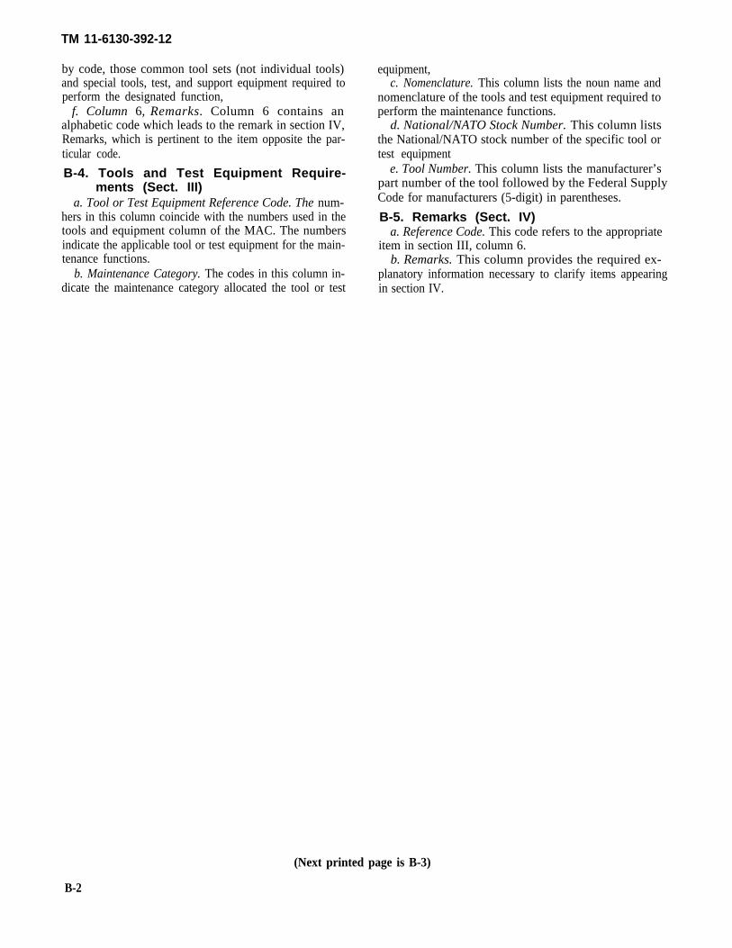
by code, those common tool sets (not individual tools)and special tools, test, and support equipment required toperform the designated function,
f. Column 6, Remarks. Column 6 contains analphabetic code which leads to the remark in section IV,Remarks, which is pertinent to the item opposite the par-ticular code.
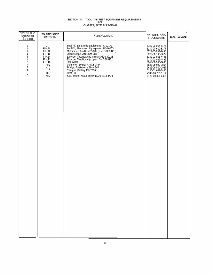
B-4. Tools and Test Equipment Require-ments (Sect. III)
a. Tool or Test Equipment Reference Code. The num-hers in this column coincide with the numbers used in thetools and equipment column of the MAC. The numbersindicate the applicable tool or test equipment for the main-tenance functions.
b. Maintenance Category. The codes in this column in-dicate the maintenance category allocated the tool or test
equipment,c. Nomenclature. This column lists the noun name and
nomenclature of the tools and test equipment required toperform the maintenance functions.
d. National/NATO Stock Number. This column liststhe National/NATO stock number of the specific tool ortest equipment
e. Tool Number. This column lists the manufacturer’spart number of the tool followed by the Federal Supply Code for manufacturers (5-digit) in parentheses.
B-5. Remarks (Sect. IV)a. Reference Code. This code refers to the appropriate
item in section III, column 6.b. Remarks. This column provides the required ex-
planatory information necessary to clarify items appearingin section IV.
(Next printed page is B-3)
B-2
SECTION II MAINTENANCE ALLOCATION CNARTFOR
CHARGER, BATTERY PP- 7286/U
B-3
TOOL OR TESTEQUIPMENTREF CODE
123456789
101112
SECTION III TOOL AND TEST EQUIPMENT REQUIREMENTSFOR
CHARGER, BATTERY PP-7286/U
MAINTENANCECATEGORY NOMENCLATURE
OF,H,DF,H,DF,H,DF,H,DF,H,DF,H,D
H,DH, D
DH,DH,D
Tool Kit, Electronic Equipment TK-101/GTool Kit, Electronic Eqduipment TK-105/GMultimeter, AN/USM-223/U (Rs TS-353 B/U)Oscilloscope, AN/USM-281Extender Test Board (23-pins) SMD 889125Extender Test Board (41 pins) SMD 889122Stop WatchVoltmeter, Digital AN/GSM-64Bridge, Resistance ZM-4B/UCharger, Battery PP-7286/UHeat GullKey, Socket Head Screw (3/16" x 13 1/2")
NATIONAL NATOSTOCK NUMBER
5180-00-064-51785180-00-610-81776625-00-999-74656625-00-106-96226130-01-066-44966130-01-066-44956645-00-903-16966625-00-022-78946625-00-500-09376130-01-041-34904940-00-785-11625120-00-821-3459
TOOL NUMBER
B-4

A
B
C
D
SECTION IV. REMARKS FORCHARGER, BATTERY PP-7286/U
1REFERENCE
REMARKS
FUSES
LAMPS AND INTERNAL 9-VOLT MEMORY BATTERY (B1)
METER M1 (IF REPLACED)
TO FAULT ISOLATE TO REPLACEABLE PC BOARD ASSEMBLY
B-5
* U.S. GOVERNMENT PRINTING OFFICE : 1994 0 - 388-421 (1280)
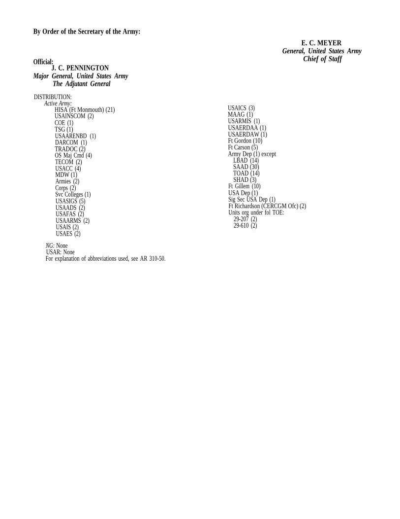
By Order of the Secretary of the Army:
Official:J. C. PENNINGTON
Major General, United States ArmyThe Adjutant General
DISTRIBUTION:Active Army:
HISA (Ft Monmouth) (21)USAINSCOM (2)COE (1)TSG (1)USAARENBD (1)DARCOM (1)TRADOC (2)OS Maj Cmd (4)TECOM (2)USACC (4)MDW (1)Armies (2)Corps (2)Svc Colleges (1)USASIGS (5)USAADS (2)USAFAS (2)USAARMS (2)USAIS (2)USAES (2)
E. C. MEYERGeneral, United States Army
Chief of Staff
USAICS (3)MAAG (1)USARMIS (1)USAERDAA (1)USAERDAW (1)Ft Gordon (10)Ft Carson (5)Army Dep (1) except
LBAD (14)SAAD (30)TOAD (14)SHAD (3)
Ft Gillem (10)USA Dep (1)Sig Sec USA Dep (1)Ft Richardson (CERCGM Ofc) (2)Units org under fol TOE:
29-207 (2)29-610 (2)
NG: NoneUSAR: NoneFor explanation of abbreviations used, see AR 310-50.


PIN: 043844-001
This fine document...
Was brought to you by me:
Liberated Manuals -- free army and government manuals
Why do I do it? I am tired of sleazy CD-ROM sellers, who take publicly available information, slap “watermarks” and other junk on it, and sell it. Those masters of search engine manipulation make sure that their sites that sell free information, come up first in search engines. They did not create it... They did not even scan it... Why should they get your money? Why are not letting you give those free manuals to your friends?
I am setting this document FREE. This document was made by the US Government and is NOT protected by Copyright. Feel free to share, republish, sell and so on.
I am not asking you for donations, fees or handouts. If you can, please provide a link to liberatedmanuals.com, so that free manuals come up first in search engines:
<A HREF=http://www.liberatedmanuals.com/>Free Military and Government Manuals</A>
– SincerelyIgor Chudovhttp://igor.chudov.com/
– Chicago Machinery Movers