ChargePro 620 Electric Vehicle Charging Station ...
6
ChargePro 620 Electric Vehicle Charging Station Installation Guide Contents Page 1 Cover Sheet Page 2 Safety and Compliance Page 3 Pedestal Mount Installation Page 4 Pedestal Mount Installation (cont) Page 5 Wall/Pole Mount Installation Page 6 Wall/Pole Mount Installation (cont) SemaConnect, Inc. 4961 Telsa Drive, Suite A * Bowie, MD 20715 301-352-3730 * www.semaconnect.com Wall Mount Pole Mount Pedestal Mount
Transcript of ChargePro 620 Electric Vehicle Charging Station ...
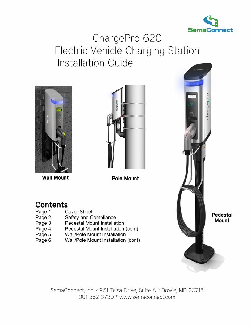
ChargePro 620 Electric Vehicle Charging Station Installation Guide
Contents Page 1 Cover Sheet Page 2 Safety and Compliance Page 3 Pedestal Mount Installation Page 4 Pedestal Mount Installation (cont) Page 5 Wall/Pole Mount Installation Page 6 Wall/Pole Mount Installation (cont)
SemaConnect, Inc. 4961 Telsa Drive, Suite A * Bowie, MD 20715 301-352-3730 * www.semaconnect.com
Wall Mount Pole Mount
Pedestal Mount
SemaConnect, Inc. www.semaconnect.com rev. 201203
Safety and Compliance
This document provides instructions to install the ChargePro™ 620 Charging Station and should not be used for any
other product. This product must be installed in accordance with the National Electrical Code (NEC) or the Canadian
Electrical Code (CEC) whichever is applicable. Consult a licensed contractor and/or electrician before installation to
ensure compliance with local building practices, climate conditions, safety standards, and state and local codes. Under
no circumstances will compliance with the information in this guide relieve the installer of responsibility to
comply with all applicable codes and safety standards.
This document describes the most common installation and mounting methods. Contact SemaConnect where it is not
possible to perform an installation using the procedures provided in this document. SemaConnect is not responsible for
damages that may occur during or as a result of installation.
IN NO EVENT SHALL SEMACONNECT, INC. OR ITS AUTHORIZED DISTRIBUTORS BE LIABLE FOR ANY
INDIRECT, INCIDENTAL, SPECIAL, PUNITIVE, OR CONSEQUENTIAL DAMAGES, INCLUDING WITHOUT
LIMITATION, LOST PROFITS, LOST DATA, LOSS OF USE, COST OF COVER, OR LOSS OR DAMAGE TO THE
CHARGEPRO™ 620 CHARGING STATION ARISING OUT OF OR RELATING TO THE USE OR INABILITY TO USE
THIS GUIDE, EVEN IF SEMACONNECT, INC. OR ITS AUTHORIZED DISTRIBUTORS HAVE BEEN ADVISED OF
THE POSSIBILITY OF SUCH DAMAGES.
ChargePro™ 620 Charging Station is a trademark of SemaConnect, Inc. All other products or services mentioned are
the trademarks, service marks, registered trademarks or registered service marks of their respective owners.
Copyright ©2010 SemaConnect, Inc. All rights reserved.
This material is protected by the copyright laws of the United States and other countries. It may not be modified,
reproduced or distributed without the prior, express written consent of SemaConnect, Inc.
Detai led Instal lat ion Instructions avai lable at www.semaconnect.com
SemaConnect, Inc. www.semaconnect.com rev. 201203
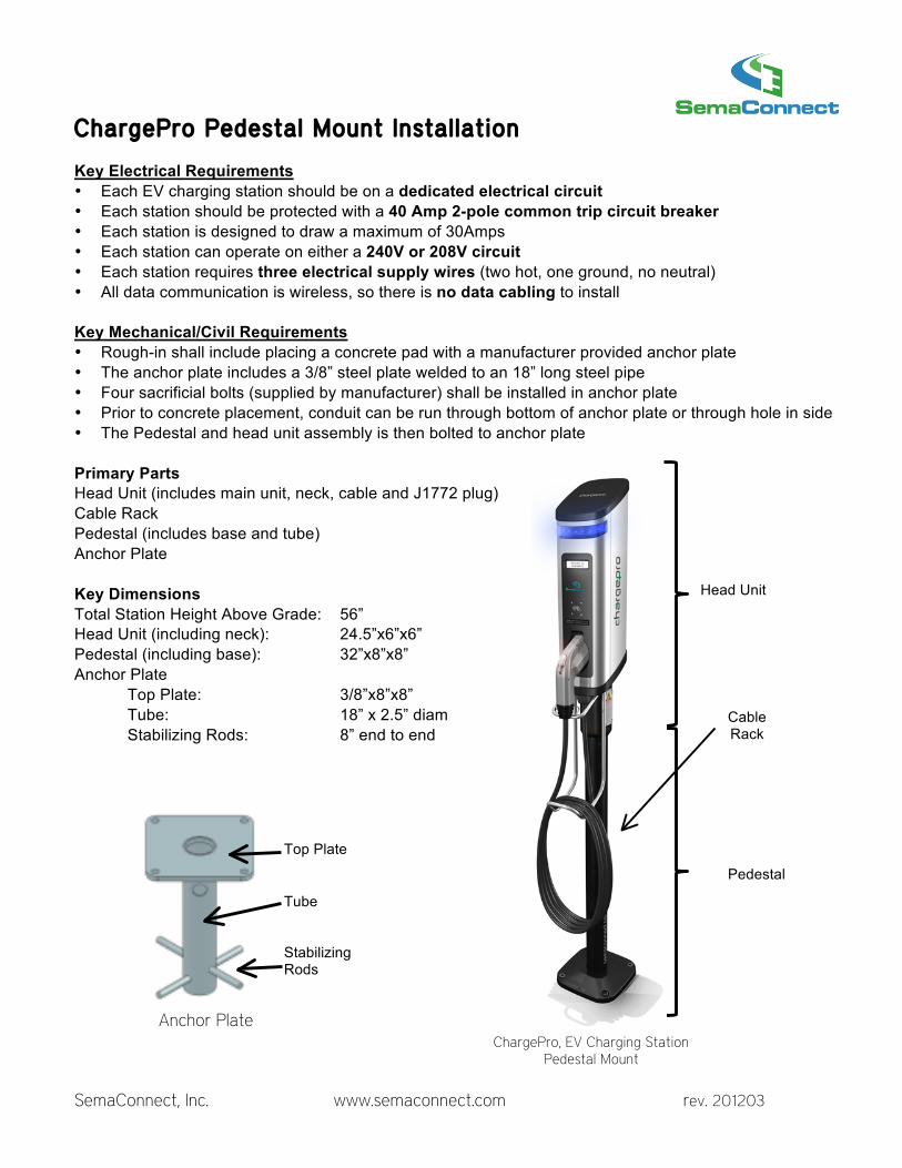
ChargePro Pedestal Mount Instal lat ion Key Electrical Requirements • Each EV charging station should be on a dedicated electrical circuit • Each station should be protected with a 40 Amp 2-pole common trip circuit breaker • Each station is designed to draw a maximum of 30Amps • Each station can operate on either a 240V or 208V circuit • Each station requires three electrical supply wires (two hot, one ground, no neutral) • All data communication is wireless, so there is no data cabling to install Key Mechanical/Civil Requirements • Rough-in shall include placing a concrete pad with a manufacturer provided anchor plate • The anchor plate includes a 3/8” steel plate welded to an 18” long steel pipe • Four sacrificial bolts (supplied by manufacturer) shall be installed in anchor plate • Prior to concrete placement, conduit can be run through bottom of anchor plate or through hole in side • The Pedestal and head unit assembly is then bolted to anchor plate Primary Parts Head Unit (includes main unit, neck, cable and J1772 plug) Cable Rack Pedestal (includes base and tube) Anchor Plate Key Dimensions Total Station Height Above Grade: 56” Head Unit (including neck): 24.5”x6”x6” Pedestal (including base): 32”x8”x8” Anchor Plate Top Plate: 3/8”x8”x8” Tube: 18” x 2.5” diam Stabilizing Rods: 8” end to end
Head Unit
Cable Rack
Pedestal
Anchor Plate
Stabilizing Rods
Tube
Top Plate
ChargePro, EV Charging Station Pedestal Mount

SemaConnect, Inc. www.semaconnect.com rev. 201203
ChargePro Pedestal Mount Instal lat ion (cont) Rough-In Steps A. Install circuit breaker, run electrical conduit B. Construct concrete form (typical footprint for one station: 24” x 24”) C. Place anchor plate and run conduit through anchor plate D. Embed anchor plate in concrete Final Assembly Steps A. Attach cable rack to head unit (4 set screws) B. Attach Pedestal to Anchor plate (4 anchor bolts) C. Align Pedestal for Plumb (4 set screws) D. Attach Head Unit to Pedestal (4 tamper resistant screws) E. Connect three electrical supply wires via access plate F. Power up charging station by turning on circuit breaker G. Station will automatically communicate with network and initialize itself (using cellular signal) H. Successful power-up is indicated by a steady blue LED light and welcome message on LCD Example Installation
1. Prep for Concrete Placement 2. Aligning Pedestal
4. Finished Concrete Pad
5. Final Installation
3. Connecting Wires

SemaConnect, Inc. www.semaconnect.com rev. 201203
ChargePro Wal l/Pole Mount Instal lat ion Key Electrical Requirements • Each EV charging station should be on a dedicated electrical circuit • Each station should be protected with a 40 Amp 2-pole common trip circuit breaker • Each station is designed to draw a maximum of 30Amps • Each station can operate on either a 240V or 208V circuit • Each station requires three electrical supply wires (two hot, one ground, no neutral) • All data communication is wireless, so there is no data cabling to install Key Mechanical/Civil Requirements • Rough-in includes:
o If Wall-Mount - Attaching Wall/Pole Mount Bracket to Wall with Four Bolts o If Pole-Mount – Attaching Wall/Pole Mount Bracket to Pole with Three Straps
• Conduit can either attach to side of bracket though pre-cut 1.0” hole, or • Conduit can enter though wall hole into back of bracket Primary Parts Head Unit (includes main unit, neck, cable and J1772 plug) Cable Rack Wall/Pole Mount Bracket Key Dimensions Total Station Height Above Grade: 56” Wall/Pole Mount Bracket Plate: 20.5” x 4.25” Head Unit (including neck): 24.5”x6”x6”
Top of Wall Mount
Bracket
Center of Conduit
Wall Hole
Top of Charging Station
Center of LCD Screen
Bottom of Wall Mount
Bracket
Wall Hole Rough
Opening Less Than
1.5in Diameter (if hidden conduit)
56.0”
47.3”
26.5”
29.5”
49.0”
28.8”
Pole-Mount Configuration
Pre-Cut 1.0” Hole Available
For Surface Conduit
Vertical Mounting Dimensions (Wal l-Mount Shown)

SemaConnect, Inc. www.semaconnect.com rev. 201203
ChargePro Wal l/Pole Mount Instal lat ion (cont) Rough-In Steps A. Attach Wall/Pole Mount Bracket
a. If Wall-Mount-Attach Wall/Pole Mount Bracket to wall with 4 bolts b. If Pole-Mount-Attach Wall/Pole Mount Bracket with three straps
B. Install circuit breaker, run electrical conduit Final Assembly Steps A. Attach cable rack to head unit (4 set screws) B. Attach Head Unit to Wall/Pole-Mount Bracket (4 tamper resistant screws) C. Connect three electrical supply wires via access plate D. Power up charging station by turning on circuit breaker E. Station will automatically communicate with network and initialize itself (using cellular signal) F. Successful power-up is indicated by a steady blue LED light and welcome message on LCD Example Installation
Connecting Supply Wires
Rough-In Complete
Finished Installation
Attaching Head Unit to Wall/Pole-Mount Bracket
Wire Access
Tamper Resistant Screws (2 each side)