Charge Transport and Recombination in Organic Solar...
119
Max Planck Institute for Polymer Research 1 Charge Transport and Recombination in Organic Solar Cells Paul Blom Max Planck Institute for Polymer Research, Mainz, Germany [email protected]
-
Upload
trinhduong -
Category
Documents
-
view
215 -
download
1
Transcript of Charge Transport and Recombination in Organic Solar...
Max Planck Institute for Polymer Research 11
Charge Transport and Recombination in
Organic Solar Cells
Paul Blom
Max Planck Institute for Polymer Research, Mainz, Germany

Max Planck Institute for Polymer Research 22
Outline
1. Charge transport in Organic Semiconductors
-Hole Transport, Electron Transport
2. Photocurrent Generation in Organic Solar Cells
-Space Charge, Recombination
3. Recombination in organic solar cells
-Bimolecular Recombination, Trap-assisted`Recombination
4. Origin of the Recombination in Organic Solar Cells
-CT electroluminescence, ideality factor
Max Planck Institute for Polymer Research 33
Vbias (V)
0.1 1 1010
-4
10-3
10-2
10-1
100
0.13m 0.3 m 0.7 m
J (
A/m
2)
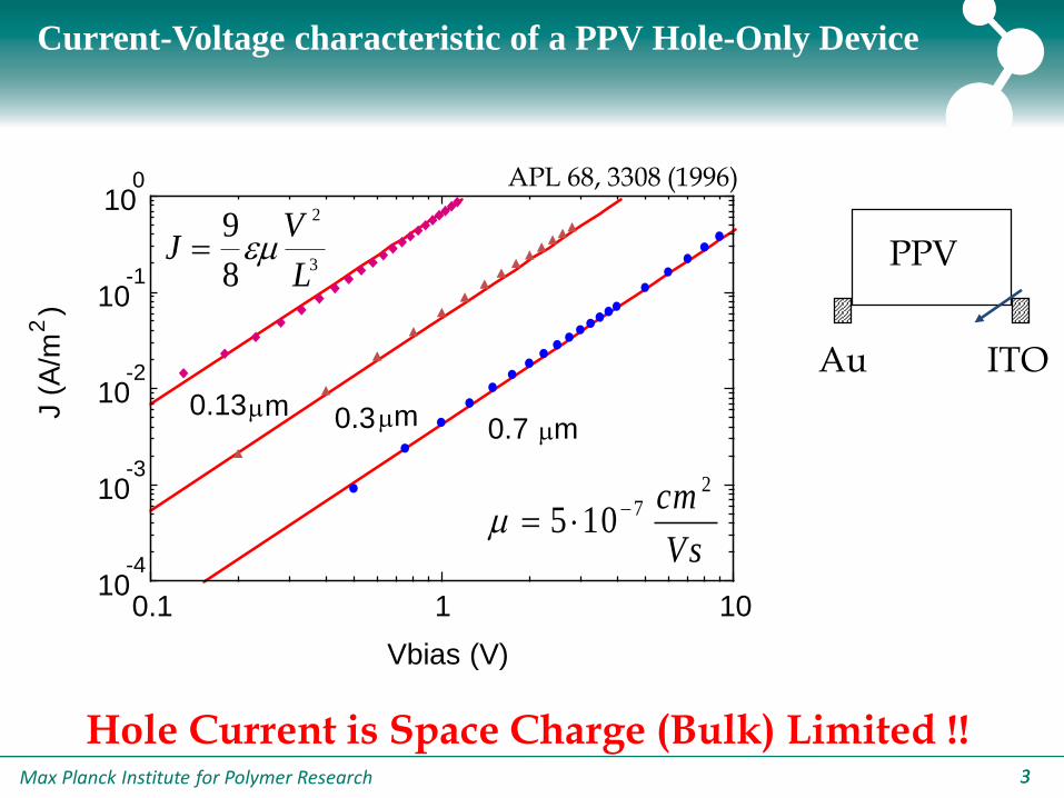
JV
L
9
8
2
3
APL 68, 3308 (1996)
Current-Voltage characteristic of a PPV Hole-Only Device
PPV
Au ITO
Hole Current is Space Charge (Bulk) Limited !!
Vs
cm 27105
Max Planck Institute for Polymer Research 44
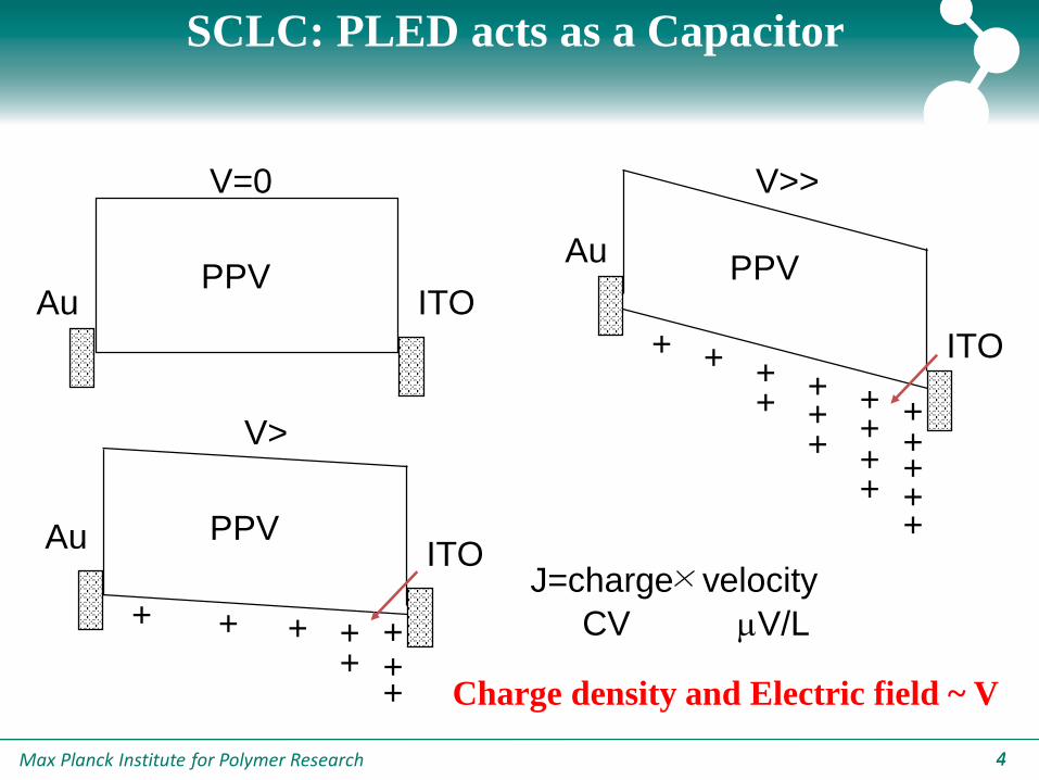
SCLC: PLED acts as a Capacitor
ITOAuPPV
V=0
ITOAu PPV
V>
+ + ++++
++
ITO
AuPPV
+ + ++
+ +
++
V>>
++
+
+
++
+
+
J=charge velocity
CV V/L
Charge density and Electric field ~ V
Max Planck Institute for Polymer Research 55
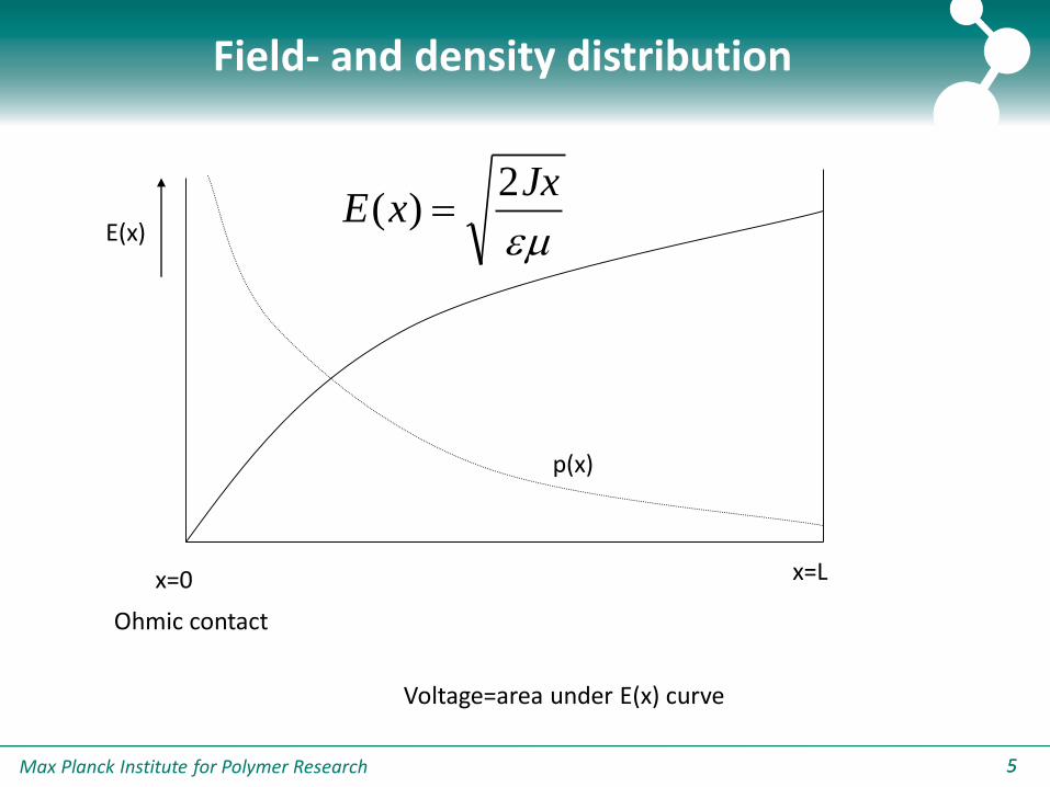
x=0 x=L
Ohmic contact
JxxE
2)(
E(x)
Voltage=area under E(x) curve
p(x)
Field- and density distribution
Max Planck Institute for Polymer Research 66
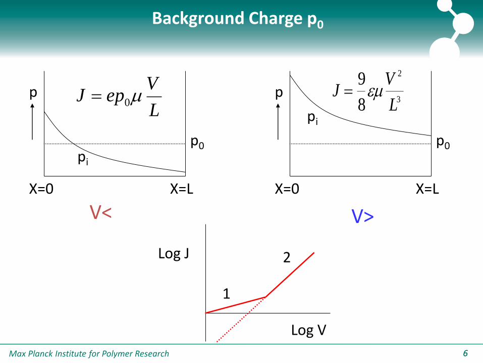
Background Charge p0
X=0 X=L
p
p0
V<
pi
X=0 X=L
p
p0
V>
pi
JV
L
9
8
2
3
L
VepJ 0
Log J
Log V
1
2
Max Planck Institute for Polymer Research 77
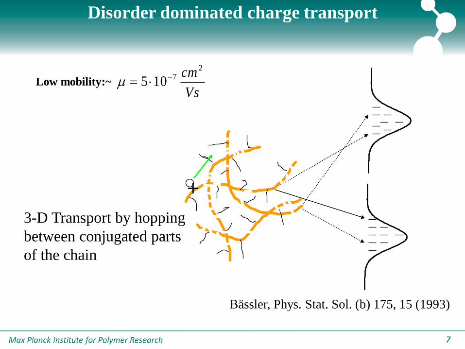
+
3-D Transport by hopping
between conjugated parts
of the chain
Disorder dominated charge transport
Low mobility:~Vs
cm 27105
Bässler, Phys. Stat. Sol. (b) 175, 15 (1993)
Max Planck Institute for Polymer Research 88
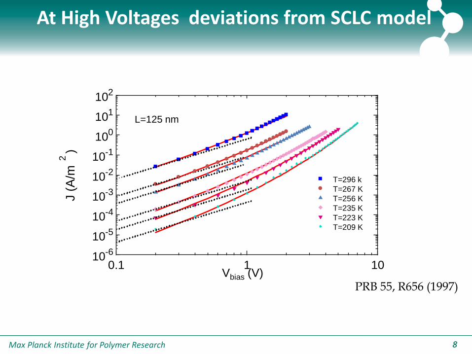
At High Voltages deviations from SCLC model
PRB 55, R656 (1997)
0.1 1 1010
-6
10-5
10-4
10-3
10-2
10-1
100
101
102
T=296 k
T=267 K
T=256 K
T=235 K
T=223 K
T=209 K
L=125 nm
J (
A/m
2)
Vbias (V)

Max Planck Institute for Polymer Research 99
1019
1020
1021
1022
1023
1024
1025
1026
10-10
10-9
10-8
10-7
FET
h,
FE
T (
m2/V
s)
p (m-3)
LED
OC1C
10-PPV
T=295 K
Mobility is Density Dependent !
Phys. Rev. Lett. 91, 216601 (2003)
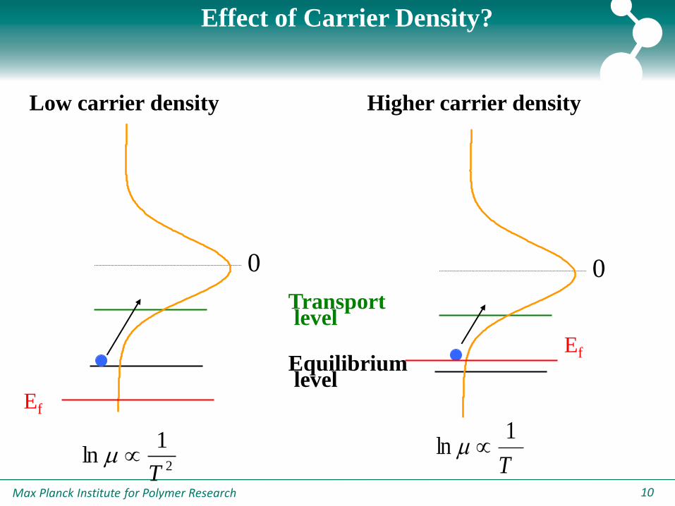
Max Planck Institute for Polymer Research 10
0
Transport level
Equilibrium level
0
Ef
Low carrier density Higher carrier density
Ef
2
1ln
T T
1ln
Effect of Carrier Density?

Max Planck Institute for Polymer Research 1111
1 10 10010
-7
10-6
10-5
10-4
10-3
10-2
10-1
100
101
T=298 K
T=272 K
T=252 K
T=233 K
V (V)
J (
A/m
2)
Theoretical model for µ(p,T,E) developed
Phys. Rev. Lett. 94, 206601 (2005)
Max Planck Institute for Polymer Research 1212
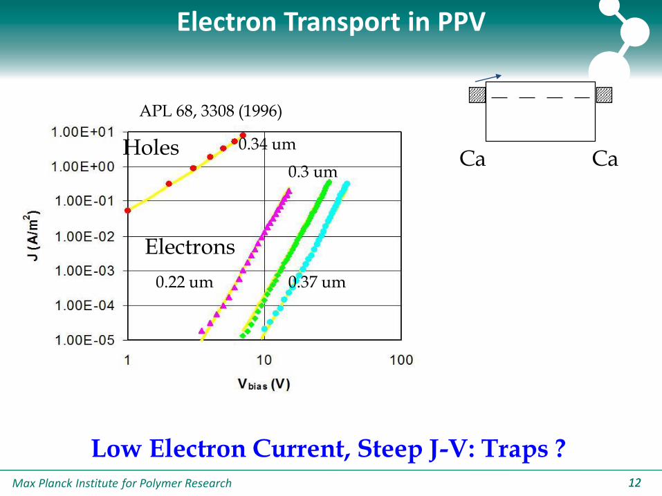
Electron Transport in PPV
Low Electron Current, Steep J-V: Traps ?
Ca CaHoles
Electrons
0.34 um
0.22 um 0.37 um
0.3 um
APL 68, 3308 (1996)
Max Planck Institute for Polymer Research 1313
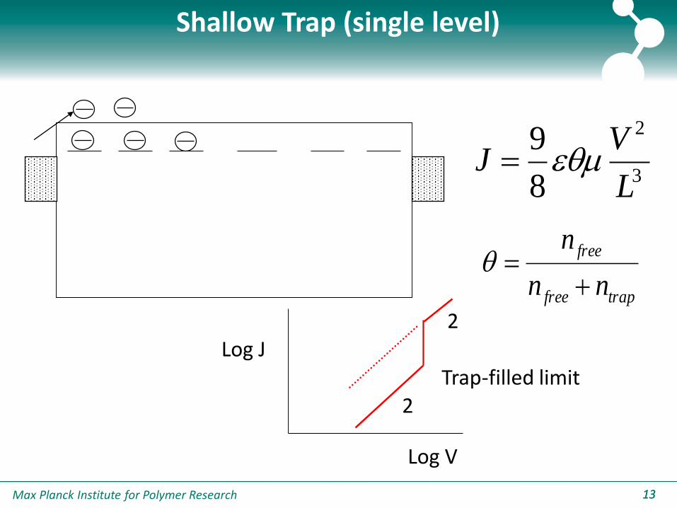
Shallow Trap (single level)
3
2
8
9
L
VJ
trapfree
free
nn
n
Log J
Log V
2
2Trap-filled limit
Max Planck Institute for Polymer Research 1414
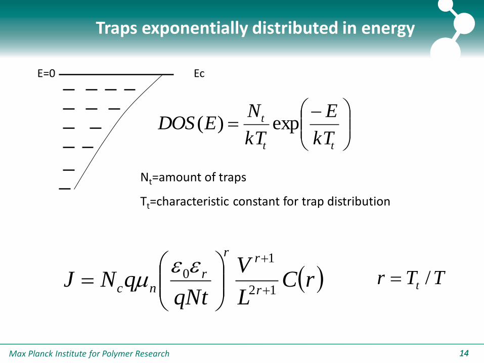
Traps exponentially distributed in energy
Ec
tt
t
kT
E
kT
NEDOS exp)(
Nt=amount of traps
Tt=characteristic constant for trap distribution
E=0
rCL
V
qNtqNJ
r
rr
rnc 12
1
0
TTr t /
Max Planck Institute for Polymer Research 1515
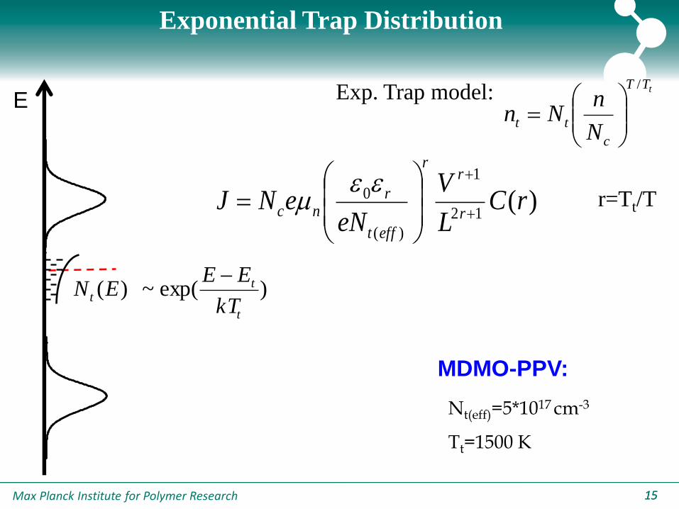
Exponential Trap Distribution
Exp. Trap model:
r=Tt/T)(12
1
)(
0 rCL
V
eNeNJ
r
rr
efft
rnc
E
)exp(~)(t
tt
kT
EEEN
Nt(eff)=5*1017 cm-3
Tt=1500 K
MDMO-PPV:
tTT
c
ttN
nNn
/
Max Planck Institute for Polymer Research 16
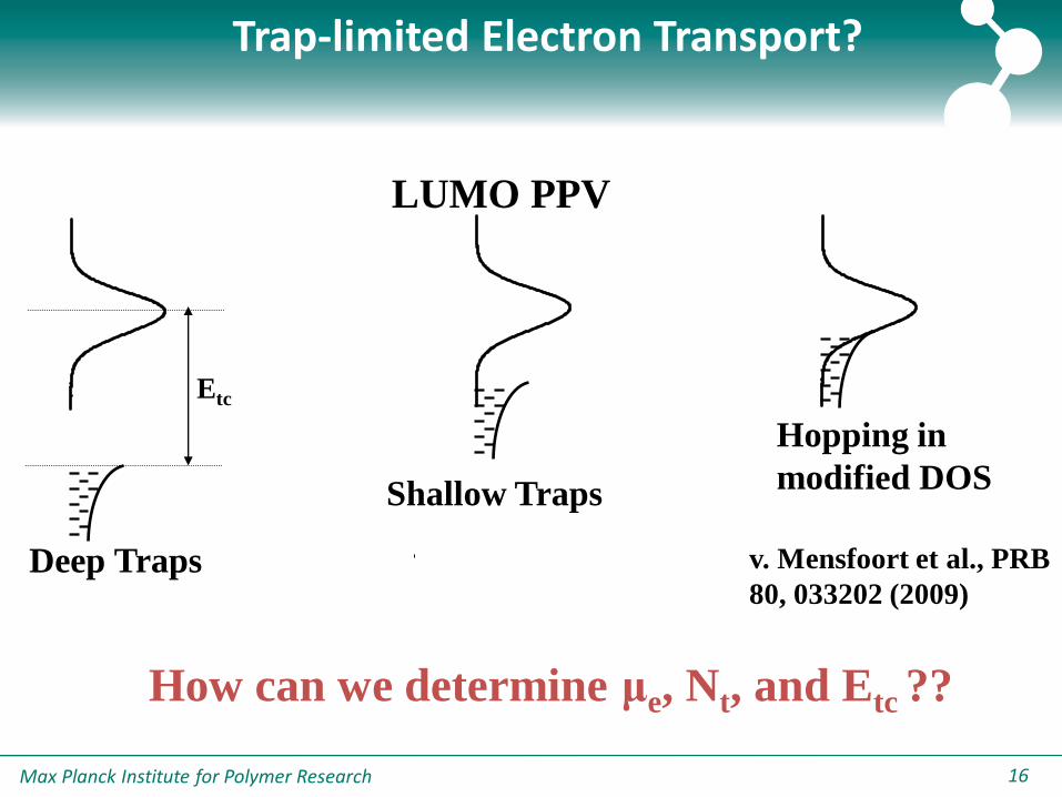
LUMO PPV
How can we determine μe, Nt, and Etc ??
Trap-limited Electron Transport?
Deep Traps
Shallow Traps
Hopping in
modified DOS
Etc
v. Mensfoort et al., PRB
80, 033202 (2009)
Max Planck Institute for Polymer Research 1717
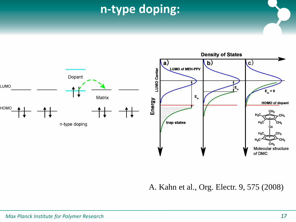
n-type doping:
A. Kahn et al., Org. Electr. 9, 575 (2008)

Max Planck Institute for Polymer Research 1818
• After n-doping:
– Electron current equal to hole current
– Temperature dependence equal to temperature dependence of hole current
– μe = μh
– Traps located > 0.4 eV below the LUMO
Phys. Rev. B. 81, 085201 (2010)
n-type doping:
Max Planck Institute for Polymer Research 1919
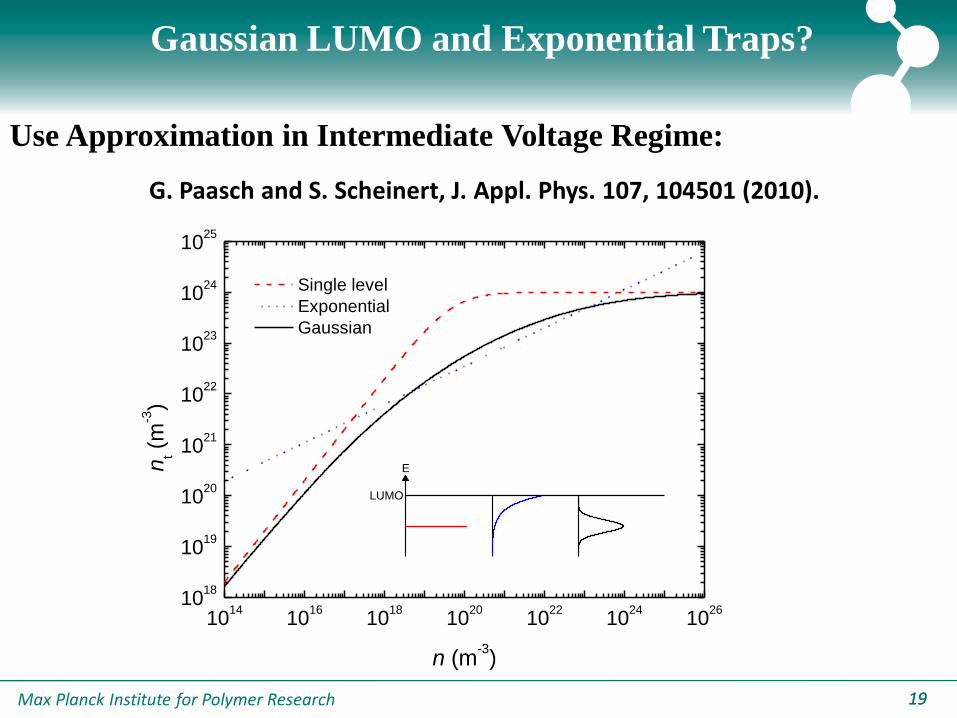
Gaussian LUMO and Exponential Traps?
Use Approximation in Intermediate Voltage Regime:
G. Paasch and S. Scheinert, J. Appl. Phys. 107, 104501 (2010).
1014
1016
1018
1020
1022
1024
1026
1018
1019
1020
1021
1022
1023
1024
1025
LUMO
E
Single level
Exponential
Gaussian
nt (
m-3)
n (m-3)
Max Planck Institute for Polymer Research 2020
10-5
10-4
10-3
10-2
10-5
10-4
10-3
10-2
10-1
100
101
2 3 4 5 6 7 8 910 20 3010
-5
10-4
10-3
295 K
275 K
255 K
235 K
215 K
195 K
Cu
rre
nt
De
nsity (
A/m
²)
(a)
(c)
NRS-PPV
L = 320 nm
MEH-PPV
L = 270 nm
295 K
273 K
251 K
230 K
211 K
Cu
rre
nt
De
nsity (
A/m
²)
OC1C
10-PPV
L = 300 nm
(b)
290 K
275 K
255 K
235 K
215 K
Cu
rre
nt
De
nsity (
A/m
²)
V-Vbi (V)
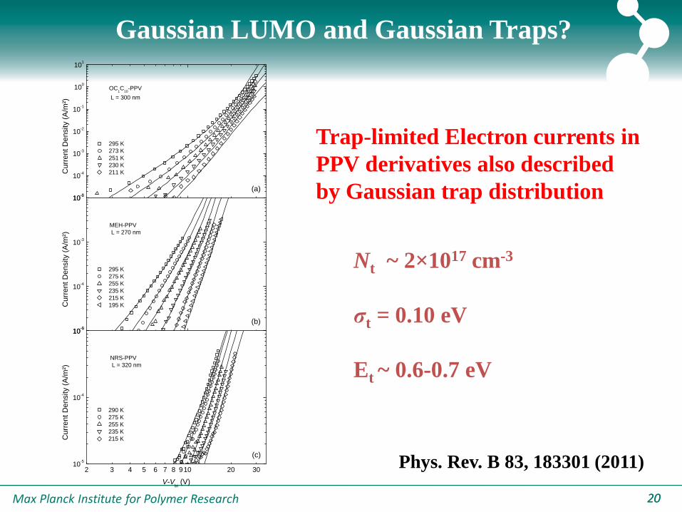
Gaussian LUMO and Gaussian Traps?
Trap-limited Electron currents in
PPV derivatives also described
by Gaussian trap distribution
Nt ~ 2×1017 cm-3
σt = 0.10 eV
Et ~ 0.6-0.7 eV
Phys. Rev. B 83, 183301 (2011)

Max Planck Institute for Polymer Research 2121
Other conjugated polymers?
0.1 1 1010
-3
10-2
10-1
100
101
102
103
104
148 nm PCPDTBT
85 nm PF10TBT
173 nm F8BT
300 nm OC1C
10-PPV
Cu
rre
nt
De
nsity (
A/m
²)
V (V)
Slope of Trap-limited Electron Current varies for different polymers

Max Planck Institute for Polymer Research 2222
Trap-free SCL current in PCBM
0.1 110
0
101
102
103
104
T = 294 K
170 nm90 nm
J [
A/m
2]
V-VRs
-Vbi [V]
3
2
08
9
L
VJ er
e2.0x10-7 m2/Vs
PEDOT:PSS
LiF
6.1 eVPEDOT:PSS
LiF/AlVbi
3.7 eV
5.2 eV
Adv. Funct. Mater. 2003, 13, No. 1
Max Planck Institute for Polymer Research 2323
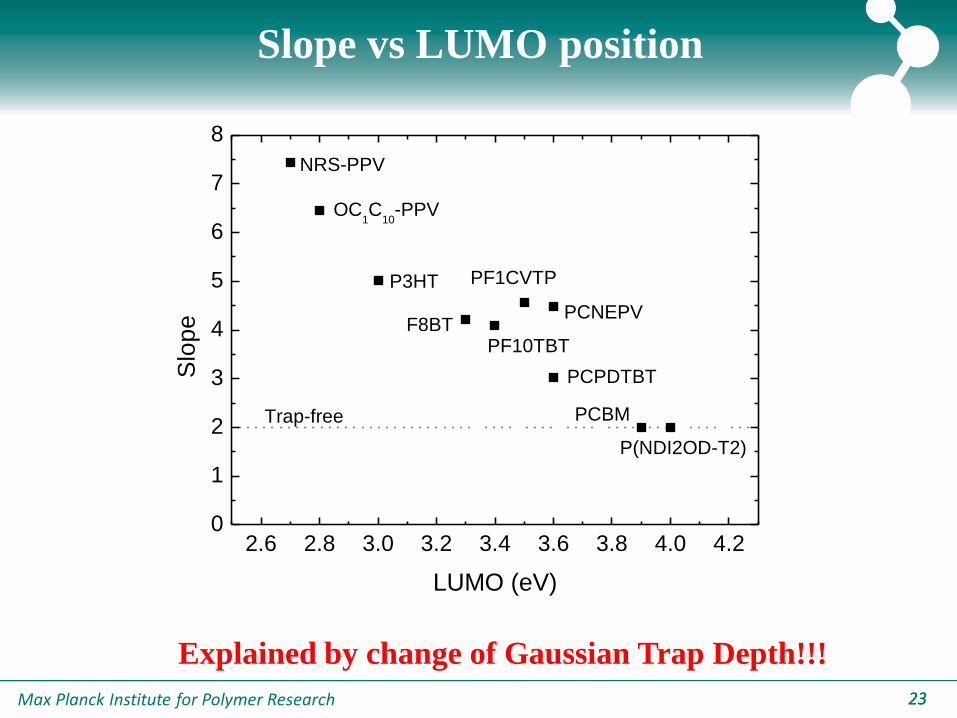
Slope vs LUMO position
2.6 2.8 3.0 3.2 3.4 3.6 3.8 4.0 4.20
1
2
3
4
5
6
7
8
Slo
pe
LUMO (eV)
NRS-PPV
OC1C
10-PPV
P3HT
F8BTPF10TBT
PCPDTBT
PCBM
P(NDI2OD-T2)
PF1CVTP
PCNEPV
Trap-free
Explained by change of Gaussian Trap Depth!!!
Max Planck Institute for Polymer Research 2424
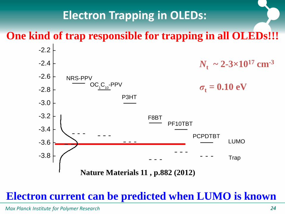
-3.8
-3.6
-3.4
-3.2
-3.0
-2.8
-2.6
-2.4
-2.2
Trap
NRS-PPVOC
1C
10-PPV
F8BTPF10TBT
PCPDTBT
P3HT
LUMO
Electron Trapping in OLEDs:
One kind of trap responsible for trapping in all OLEDs!!!
Nt ~ 2-3×1017 cm-3
σt = 0.10 eV
Electron current can be predicted when LUMO is known
Nature Materials 11 , p.882 (2012)

Max Planck Institute for Polymer Research 2525
Origin of Trap?
Photo-oxidation?
Water-polymer complexes?
Hydrated-oxygen complexes O2(H2O)2
Trap-depth 0.1-0.2 eV
Potential Deep Trap
Peter Ho et al., Adv. Mat. 21, 4747 (2009)
C. Campbell, C. Risko, J. L. Brédas, Georgia Tech
Max Planck Institute for Polymer Research 2626
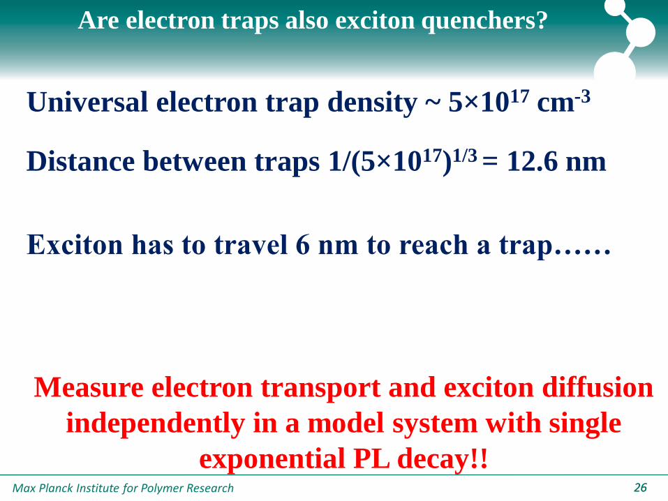
Are electron traps also exciton quenchers?
Universal electron trap density ~ 5×1017 cm-3
Distance between traps 1/(5×1017)1/3 = 12.6 nm
Exciton has to travel 6 nm to reach a trap……
Measure electron transport and exciton diffusion
independently in a model system with single
exponential PL decay!!
Max Planck Institute for Polymer Research 2727
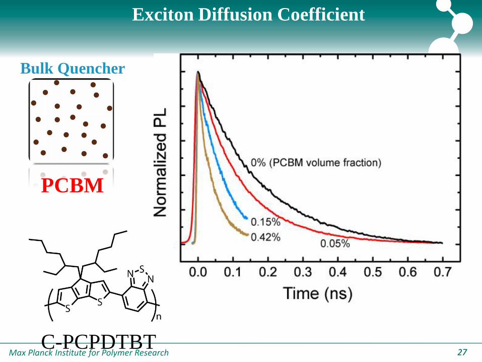
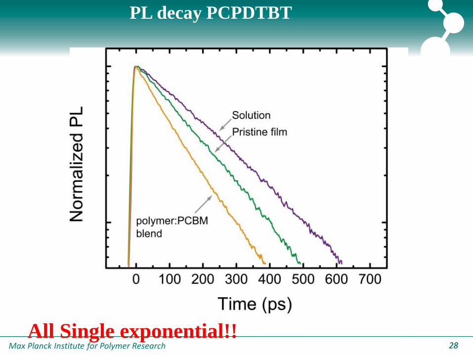
Exciton Diffusion Coefficient
Bulk Quencher
PCBM
C-PCPDTBT
Max Planck Institute for Polymer Research 2828
PL decay PCPDTBT
All Single exponential!!
Max Planck Institute for Polymer Research 2929
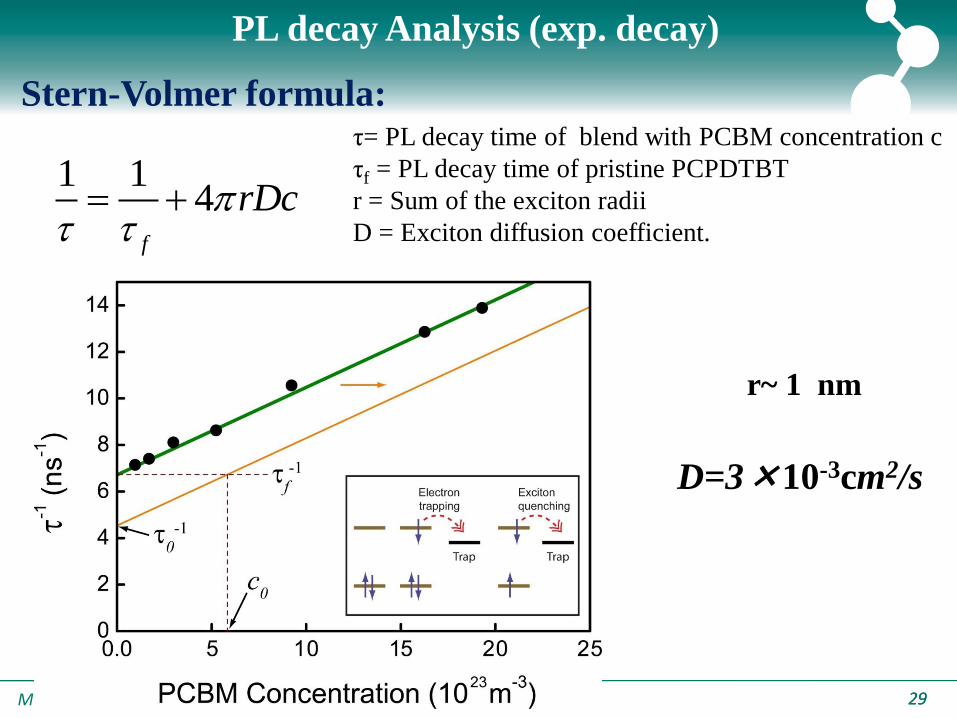
PL decay Analysis (exp. decay)
1 14
f
rDc
Stern-Volmer formula:τ= PL decay time of blend with PCBM concentration c
τf = PL decay time of pristine PCPDTBT
r = Sum of the exciton radii
D = Exciton diffusion coefficient.
r~ 1 nm
D=3×10⁻³cm2/s
Max Planck Institute for Polymer Research 3030
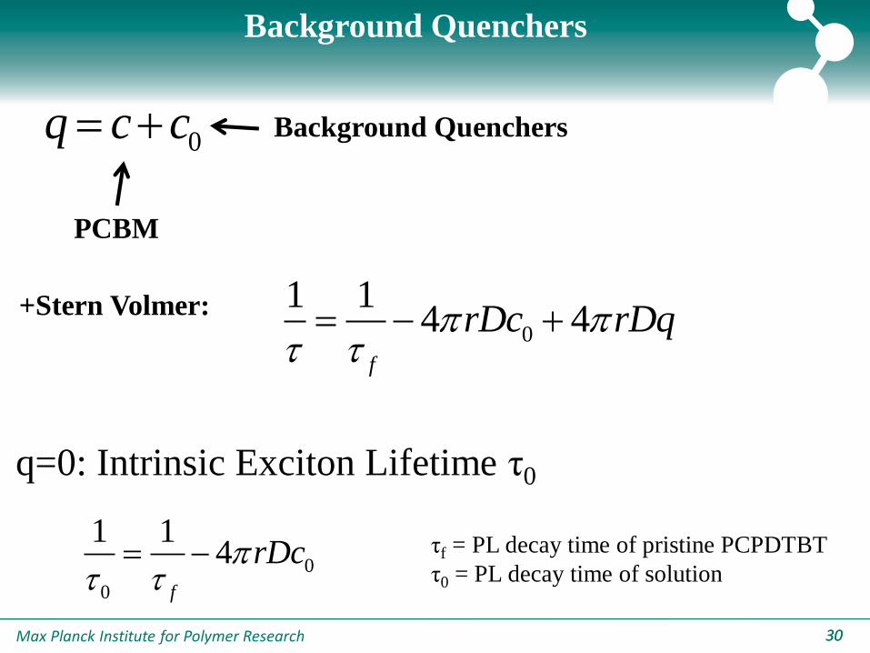
0q c c
0
1 14 4
f
rDc rDq
0
0
1 14
f
rDc
q=0: Intrinsic Exciton Lifetime τ0
Background Quenchers
PCBM
Background Quenchers
+Stern Volmer:
τf = PL decay time of pristine PCPDTBT
τ0 = PL decay time of solution

Max Planck Institute for Polymer Research 3131
Graphical Representation c0
c0=6×1017 cm-3 , equal to Ntrap electrons !!!!!
Max Planck Institute for Polymer Research 3232
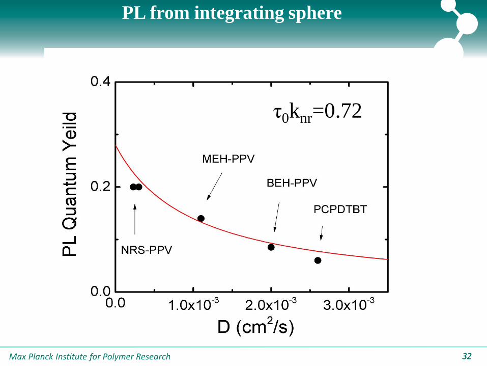
PL from integrating sphere
τ0knr=0.72
Max Planck Institute for Polymer Research 3333
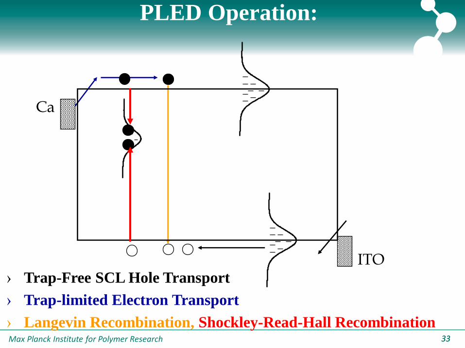
PLED Operation:
› Trap-Free SCL Hole Transport
› Trap-limited Electron Transport
› Langevin Recombination, Shockley-Read-Hall Recombination
Ca
ITO
Max Planck Institute for Polymer Research 3434
Outline
1. Charge transport in Organic Semiconductors
-Hole Transport, Electron Transport
2. Photocurrent Generation in Organic Solar Cells
-Space Charge, Recombination
3. Recombination in organic solar cells
-Bimolecular Recombination, Trap-assisted`Recombination
4. Origin of the Recombination in Organic Solar Cells
-CT electroluminescence, ideality factor
Max Planck Institute for Polymer Research 3535
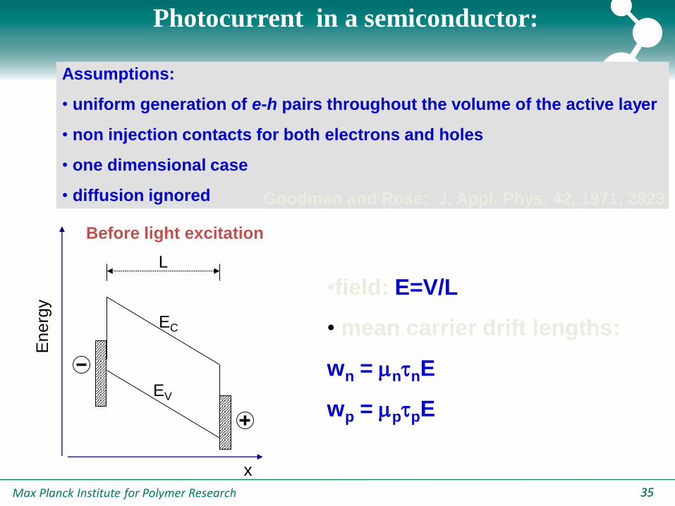
Goodman and Rose: J. Appl. Phys. 42, 1971, 2823
En
erg
y
x
L
EC
EV
Before light excitation
•field: E=V/L
• mean carrier drift lengths:
wn = nnE
wp = ppE
Assumptions:
• uniform generation of e-h pairs throughout the volume of the active layer
• non injection contacts for both electrons and holes
• one dimensional case
• diffusion ignored
Photocurrent in a semiconductor:
Max Planck Institute for Polymer Research 3636
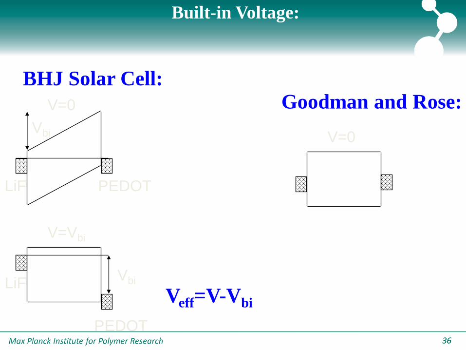
Built-in Voltage:
V=0
V=Vbi
LiF PEDOT
Vbi
LiFVbi
PEDOT
V=0
Goodman and Rose:
BHJ Solar Cell:
Veff=V-Vbi
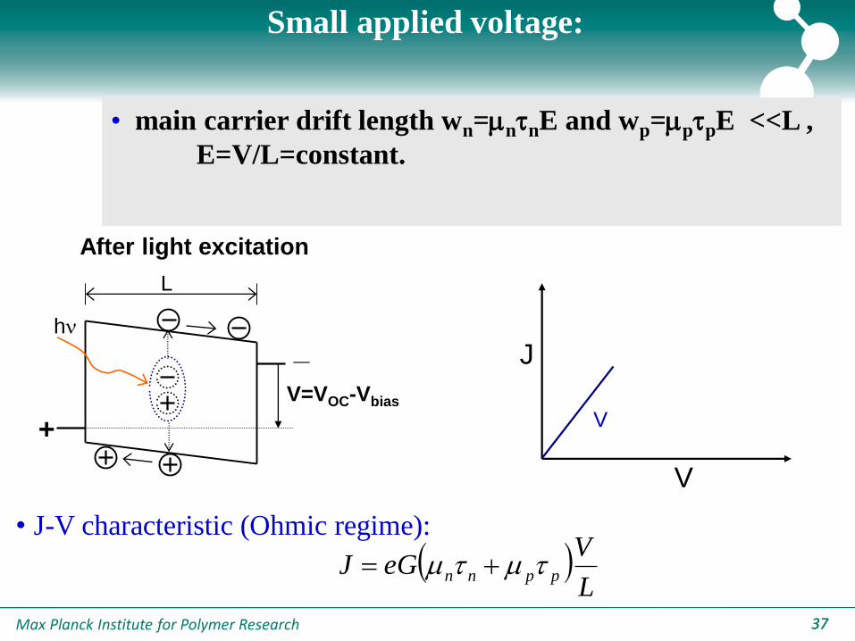
Max Planck Institute for Polymer Research 3737
• main carrier drift length wn=nnE and wp=ppE <<L ,
E=V/L=constant.
+
_hn
V=VOC-Vbias
L
• J-V characteristic (Ohmic regime):
After light excitation
L
VeGJ ppnn
J
V
V
Small applied voltage:

Max Planck Institute for Polymer Research 3838
• nn > pp , wn>> L, wp< L
Recombination ( Limited regime:
2/12/12/1 ; GVJVeGJ nn
J
V
V
V1/2+_
hn
L1
V=VOC-bias
Intermediate voltage:
Max Planck Institute for Polymer Research 3939
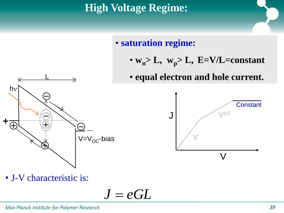
• saturation regime:
• wn> L, wp> L, E=V/L=constant
• equal electron and hole current.
• J-V characteristic is:
eGLJ
+_
hn
V=VOC-bias
L
J
V
V
V1/2
Constant
High Voltage Regime:
Max Planck Institute for Polymer Research 4040
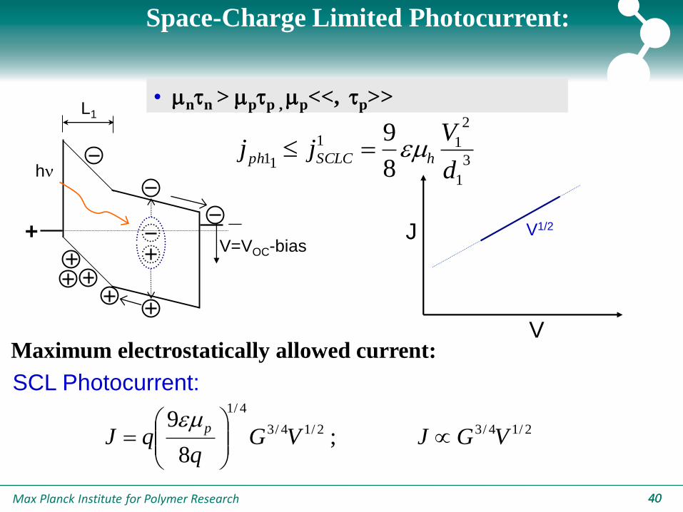
SCL Photocurrent:
J
V
V1/2+_
hn
L1
V=VOC-bias
Space-Charge Limited Photocurrent:
2/14/32/14/3
4/1
; 8
9VGJVG
qqJ
p
3
1
2
11
118
9
d
Vjj hSCLCph
Maximum electrostatically allowed current:
• nn > pp , p<<, p>>

Max Planck Institute for Polymer Research 4141
L
• J-V characteristic is:
No recombination losses:
+
_hn
V=VOC-bias
eV
kT
kTeV
kTeVeGLJJJ pn
2
1)/exp(
1)/exp(
Hughes and Sokel: J. Appl. Phys. 52, 1981, 6743
J
V
V
diffusion drift
Assumption: Diffusion neglected
Max Planck Institute for Polymer Research 42
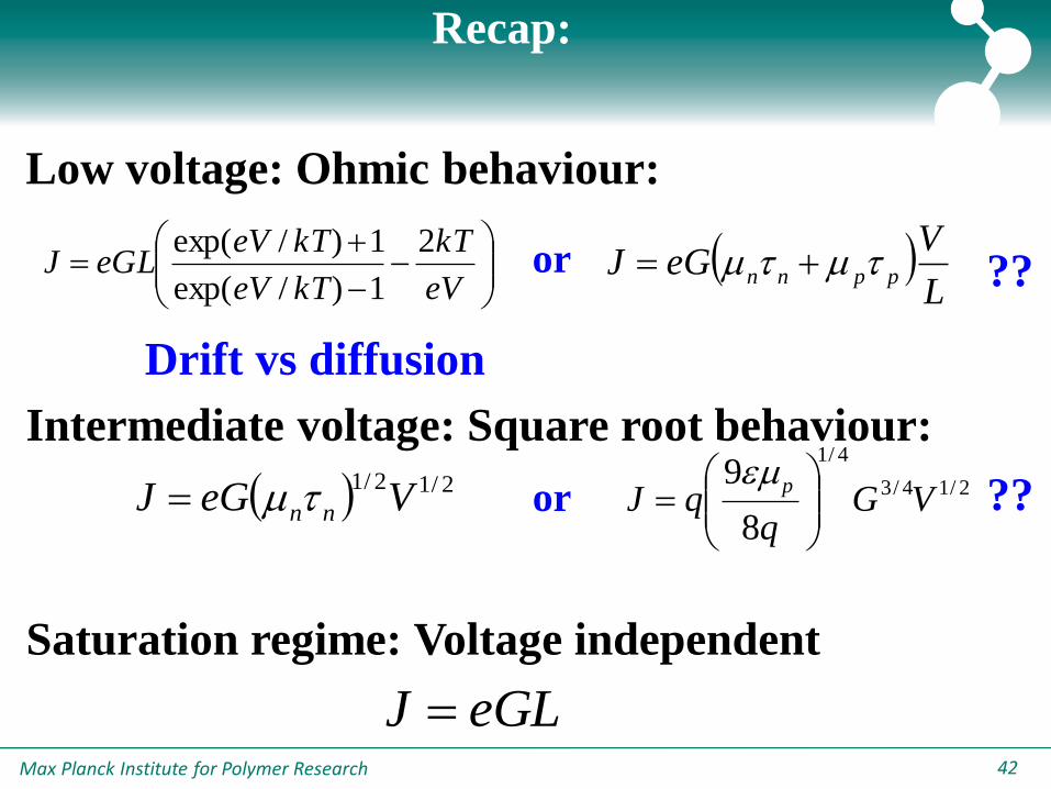
Recap:
eV
kT
kTeV
kTeVeGLJ
2
1)/exp(
1)/exp( L
VeGJ ppnn
8
92/14/3
4/1
VGq
qJp
Low voltage: Ohmic behaviour:
2/12/1VeGJ nn
eGLJ
Intermediate voltage: Square root behaviour:
Saturation regime: Voltage independent
or ??
Drift vs diffusion
or ??
Max Planck Institute for Polymer Research 4343
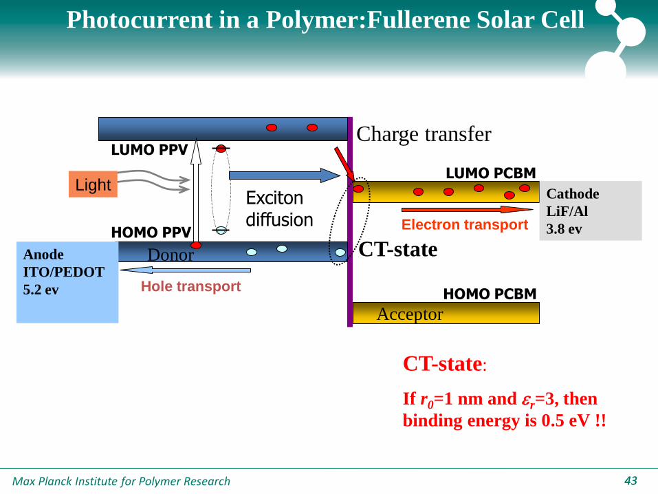
LUMO PPV
LUMO PCBM
HOMO PPV
HOMO PCBM
Excitondiffusion
Donor
Acceptor
Anode
ITO/PEDOT
5.2 ev
Cathode
LiF/Al
3.8 ev
Light
Electron transport
Hole transport
Charge transfer
CT-state
CT-state:
If r0=1 nm and r=3, then
binding energy is 0.5 eV !!
Photocurrent in a Polymer:Fullerene Solar Cell
Max Planck Institute for Polymer Research 4444
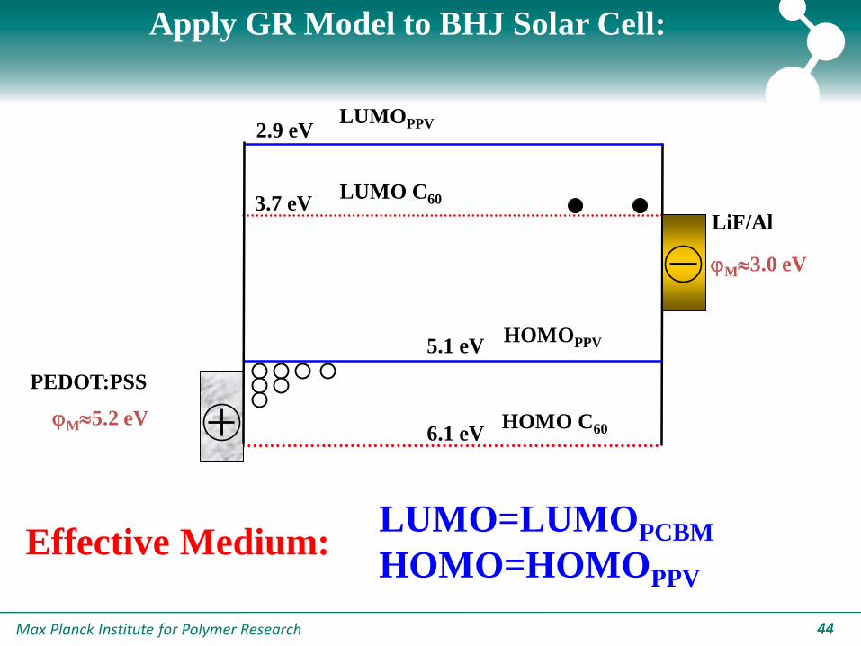
Apply GR Model to BHJ Solar Cell:
HOMOPPV
HOMO C60
LUMO C60
2.9 eV
3.7 eV
5.1 eV
6.1 eV
PEDOT:PSS
jM5.2 eV
LUMOPPV
LiF/Al
jM3.0 eV
LUMO=LUMOPCBM
HOMO=HOMOPPV
Effective Medium:
Max Planck Institute for Polymer Research 45
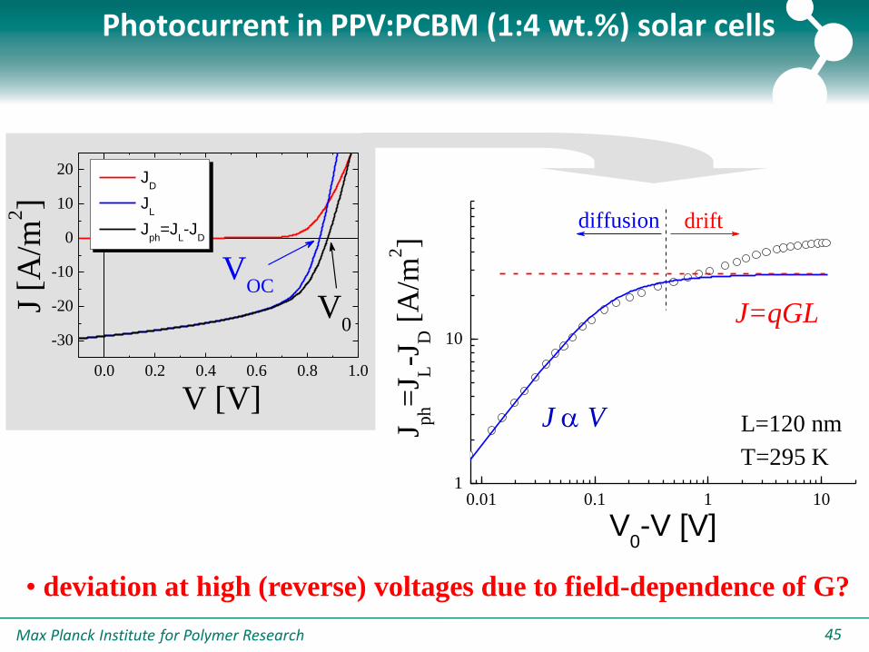
0.01 0.1 1 101
10
J ph=
J L-J
D [
A/m
2]
V0-V [V]
driftdiffusion
Photocurrent in PPV:PCBM (1:4 wt.%) solar cells
• deviation at high (reverse) voltages due to field-dependence of G?
0.0 0.2 0.4 0.6 0.8 1.0
-30
-20
-10
0
10
20
VOC
V0
JD
JL
Jph
=JL-J
D
J [A
/m2]
V [V]J V
J=qGL
L=120 nm
T=295 K

Max Planck Institute for Polymer Research 4646
0.01 0.1 1 10
0.1
1
constant G
JV MDMO-PPV:PCBM Si p/n cell
J/J
ma
x
Voc-V [V]
field dependent G
• The generation rate in blends of MDMO-PPV:PCBM is field
dependent!
Organic BHJ vs. Si-based Solar cell

Max Planck Institute for Polymer Research 4747
D D*hnD+… A-exciton
diffusion
kD(E)
kR
Free carriers
CT1 state
D… A
CT0 state
kF
Schematic diagram for charge-carrier formation in
polymer(donor)/fullerene(acceptor) films
kD - rate constant for produces free carriers (Onsager)
kF - rate constant for decay to the ground state of CT0
kR - rate constant for recombination of free carriers back to CT1
Braun: J. Chem. Phys. 80, 1984, 4157 !! eV 0.5 isenergy bindingthen
,3 and nm 1 If 0 rr
Max Planck Institute for Polymer Research 4848
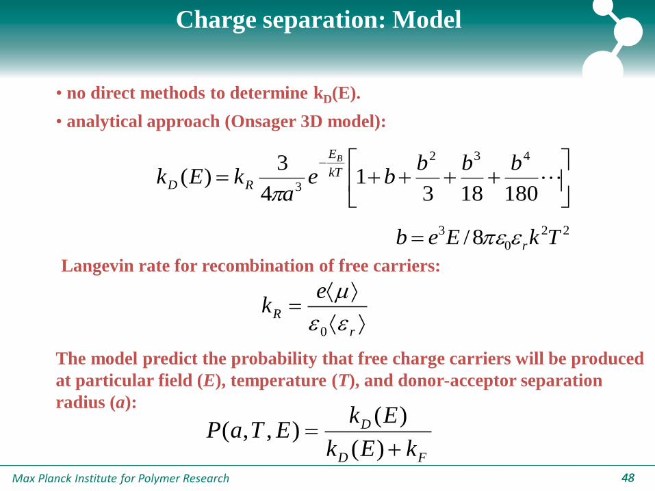
• no direct methods to determine kD(E).
• analytical approach (Onsager 3D model):
180183
14
3)(
432
3
bbbbe
akEk kT
E
RD
B
22
0
3 8/ TkEeb r
r
R
ek
0
Langevin rate for recombination of free carriers:
Charge separation: Model
The model predict the probability that free charge carriers will be produced
at particular field (E), temperature (T), and donor-acceptor separation
radius (a):
FD
D
kEk
EkETaP
)(
)(),,(

Max Planck Institute for Polymer Research 4949
Saturation Regime:
MDMO-PPV:PCBM
Saturated regime: photocurrent J=e G(E,T) L due to dissociation of
bound electron-hole pairs
Braun: J. Chem. Phys. 80, 1984, 4157
0.1 1 101
10
295 K270 K250 K230 K210 K
J ph [
A/m
2]
VOC
-V [V]
Phys. Rev. Lett., 93, 216601 (2004)
60% Jsc
At Jsc only 60% of bound
e-h pairs is dissociated !!
eGMAXL

Max Planck Institute for Polymer Research 5050
Solar Cell Device Model
Inclusion of (Langevin) recombination and G(E,T) requires
numerical modeling
10-2
10-1
100
101
100
101
data 295 K
data 250 K
q G(V) L 295 K
q G(V) L 250 K
simulation 295 K
simulation 250 K
Jlig
ht-J
dark [
A/m
2]
Voc-V [V]
Phys. Rev. B 72, 085205 (2005)
MDMO-PPV:PCBM
Max Planck Institute for Polymer Research 5151
-0.8 -0.6 -0.4 -0.2 0.0 0.2 0.4 0.6 0.8 1.0
-30
-20
-10
0
10
LiF/Al
Ag
Au
Pd
J L [
A/m
2]
V [V]
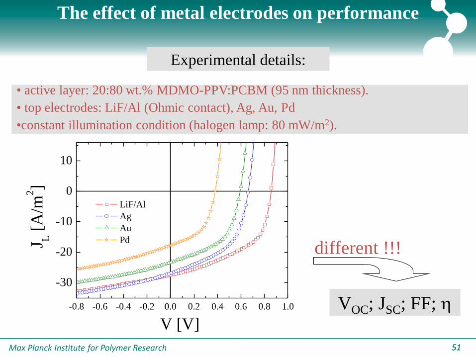
The effect of metal electrodes on performance
Experimental details:
• active layer: 20:80 wt.% MDMO-PPV:PCBM (95 nm thickness).
• top electrodes: LiF/Al (Ohmic contact), Ag, Au, Pd
•constant illumination condition (halogen lamp: 80 mW/m2).
different !!!
VOC; JSC; FF; h
Max Planck Institute for Polymer Research 5252
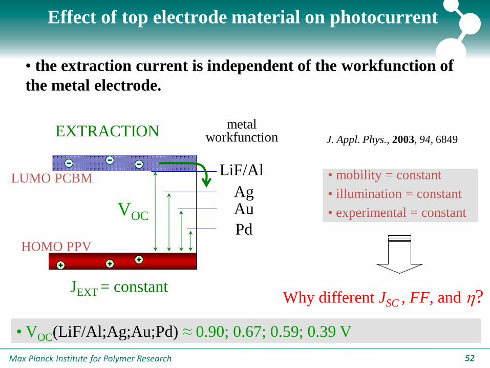
Effect of top electrode material on photocurrent
• the extraction current is independent of the workfunction of
the metal electrode.
JEXT = constant
LUMO PCBM
HOMO PPV
LiF/Al
AgAu
Pd
VOC
EXTRACTION metal
workfunction
• VOC(LiF/Al;Ag;Au;Pd) ≈ 0.90; 0.67; 0.59; 0.39 V
J. Appl. Phys., 2003, 94, 6849
• mobility = constant
• illumination = constant
• experimental = constant
Why different JSC , FF, and h?
Max Planck Institute for Polymer Research 5353
0.0 0.2 0.4 0.6 0.8 1.0 1.2 1.4 1.6
5
10
15
20
25
30
35
J ph=
J L-J
D [
A/m
2]
V0-V [V]
PdAu
Ag
LiF/Al
Ag
Au
Pd
Calculation
LiF/Al
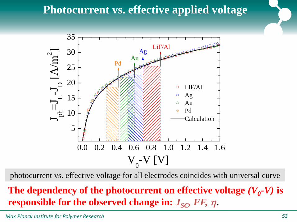
The dependency of the photocurrent on effective voltage (V0-V) is
responsible for the observed change in: JSC, FF, h.
Photocurrent vs. effective applied voltage
photocurrent vs. effective voltage for all electrodes coincides with universal curve

Max Planck Institute for Polymer Research 5454
Model results
once the open-circuit voltage (VOC) is known → all other device
parameters can be elucidated.
Appl. Phys. Lett., 2004, 85, 970
0.0 0.2 0.4 0.6 0.8 1.0 1.2 1.4 1.6
0
5
10
15
20
25
30
35LiF/Al
Ag
Au
Pd
PMAX
[W/m2]
JSC
[A/m2]
VOC
[V]

Max Planck Institute for Polymer Research 5555
Solar cell performance versus PCBM fraction ?
20 30 40 50 60 70 80 90 100
0.0
0.2
0.4
0.6
0.8
1.0
weight percentage PCBM [wt.-%]
pow
er
con
vers
ion e
ffic
iency
Why do the devices perform better when the absorption is less?
Max Planck Institute for Polymer Research 5656
20 30 40 50 60 70 80 90 10010
-11
10-10
10-9
10-8
10-7
10-6
e
h
weight percentage PCBM [wt.-%]
[m
2/V
s]
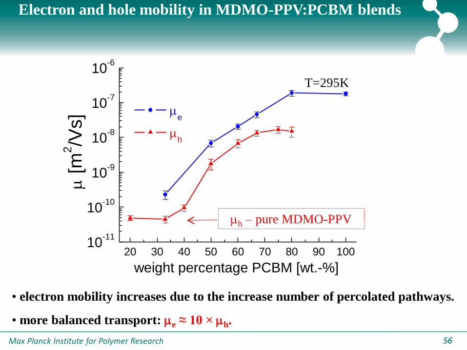
Electron and hole mobility in MDMO-PPV:PCBM blends
h – pure MDMO-PPV
T=295K
• electron mobility increases due to the increase number of percolated pathways.
• more balanced transport: e ≈ 10 × h.

Max Planck Institute for Polymer Research 57
0.01 0.1 1 10
1
10
100
80 wt.% (L=106nm) 67 wt.% (L=75 nm) 50 wt.% (L=85 nm)
J ph=
J L-J
D [
A/m
2]
V0-V [V]
PPV:PCBM solar cells with different composition
saturation JSAT=qGMAXL
L = active layer thickness.
GMAX = maximum generated
free electrons and holes.

Max Planck Institute for Polymer Research 58
20 30 40 50 60 70 80 90 100
1.0
1.5
2.0
2.5
3.0
3.5
4.0
4.5
5.0
5.5
weight percentage PCBM [wt.-%]
GM
AX [
102
7m
-3s-1
]
Maximum generation rate in PPV:PCBM solar cells
More recombination !? Less absorption
• more recombination: due to an increase number of isolated PCBM clusters.
• less absorption: due to decreasing fraction of the absorbing material (MDMO-PPV).

Max Planck Institute for Polymer Research 59
Photocurrent versus effective voltage
20 40 60 80 10010
-11
10-9
10-7
electrons
holes
wt.% PCBM
mob
ilit
y [
m2/V
s]
0.01 0.1 1 10
0.1
1
Jp
h/q
GM
AXL
V0(J
ph=0) - V [V]
80 wt.%
50 wt.%
Calculation:
80 wt.% (reference)
50 wt.% ( varied)
50 wt.% (+<r> varied)
JSC
Max Planck Institute for Polymer Research 60
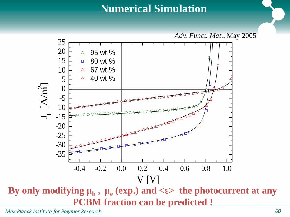
Numerical Simulation
-0.4 -0.2 0.0 0.2 0.4 0.6 0.8 1.0
-35
-30
-25
-20
-15
-10
-5
0
5
10
15
20
25
95 wt.%80 wt.%67 wt.%40 wt.%
J L [
A/m
2]
V [V]
Adv. Funct. Mat., May 2005
By only modifying μh , μe (exp.) and <ε> the photocurrent at any
PCBM fraction can be predicted !
Max Planck Institute for Polymer Research 6161
3.4 3.6 3.8 4.0 4.2 4.4 4.6 4.8
10-11
10-10
10-9
10-8
10-7
O
O*
O
O
*1
3 ran
O
O*
O
O
*1
3 ran
L1L
V1
G
L1L
V1
G
[
m2/V
s]
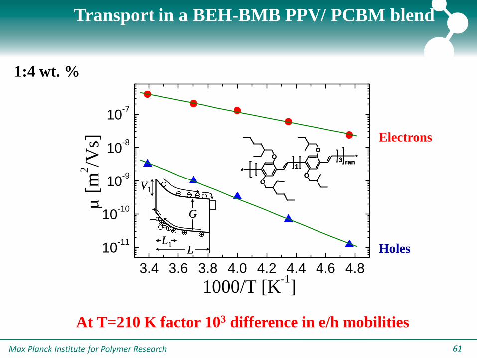
1000/T [K-1]
Electrons
Holes
At T=210 K factor 103 difference in e/h mobilities
Transport in a BEH-BMB PPV/ PCBM blend
1:4 wt. %
Max Planck Institute for Polymer Research 6262
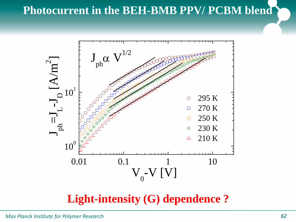
0.01 0.1 1 10
100
101
295 K
270 K
250 K
230 K
210 K
J ph=
J L-J
D [
A/m
2]
V0-V [V]
Jph V
1/2
Light-intensity (G) dependence ?
Photocurrent in the BEH-BMB PPV/ PCBM blend
Max Planck Institute for Polymer Research 6363
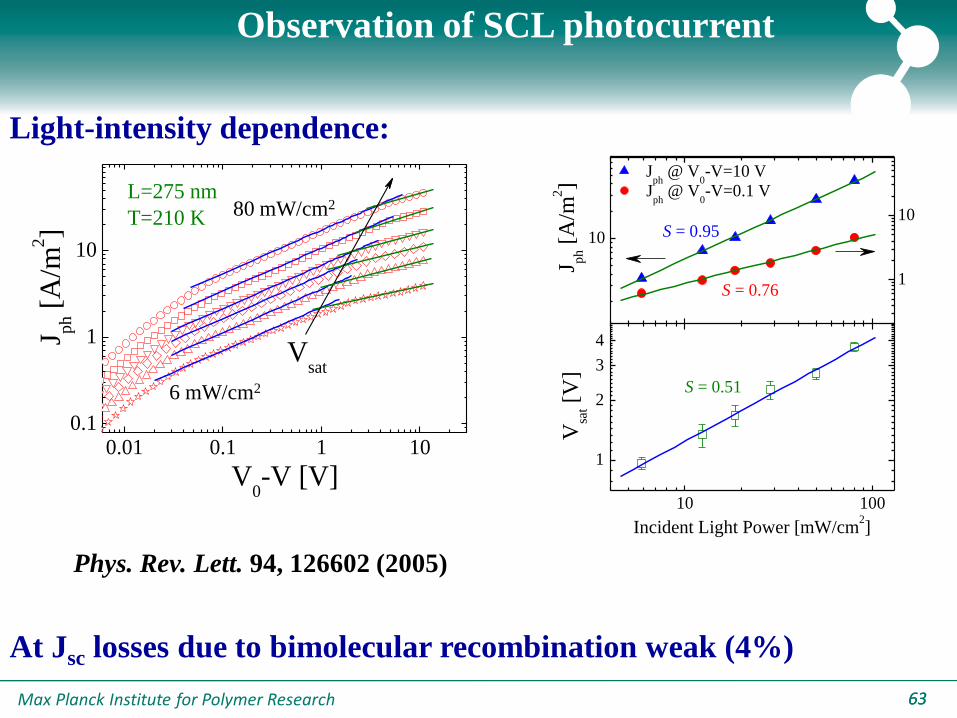
Observation of SCL photocurrent
0.01 0.1 1 100.1
1
10
J ph [
A/m
2]
V0-V [V]
L=275 nm
T=210 K
Vsat
10
1
10
10 100
1
2
3
4
Jph
@ V0-V=10 V
S = 0.76
J ph [
A/m
2]
S = 0.95
Jph
@ V0-V=0.1 V
S = 0.51
Vsa
t [V
]
Incident Light Power [mW/cm2]
Light-intensity dependence:
80 mW/cm2
6 mW/cm2
At Jsc losses due to bimolecular recombination weak (4%)
Phys. Rev. Lett. 94, 126602 (2005)
Max Planck Institute for Polymer Research 6464
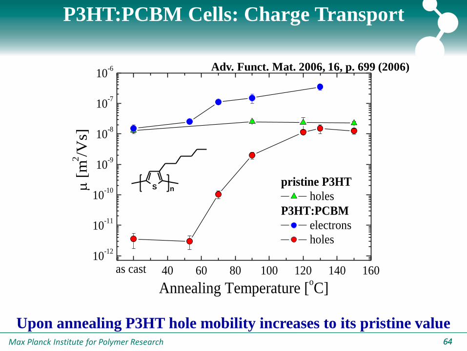
P3HT:PCBM Cells: Charge Transport
20 40 60 80 100 120 140 160
10-12
10-11
10-10
10-9
10-8
10-7
10-6
pristine P3HT
holes
P3HT:PCBM
electrons
holes
as cast
[
m2/V
s]
Annealing Temperature [oC]
Upon annealing P3HT hole mobility increases to its pristine value
Adv. Funct. Mat. 2006, 16, p. 699 (2006)
S n

Max Planck Institute for Polymer Research 6565
P3HT:PCBM Cells: Modeling
0.01 0.1 1 10
1
10
100
as-cast
Annealed:
70 oC
120 oC
Jp
h [A
/m2]
V0-V [V]
JSC
eGMAXL
eGMAXL
1) Increase of GMAX upon annealing
2) Presence of V1/2 regime in non-optimal devices
Max Planck Institute for Polymer Research 6666
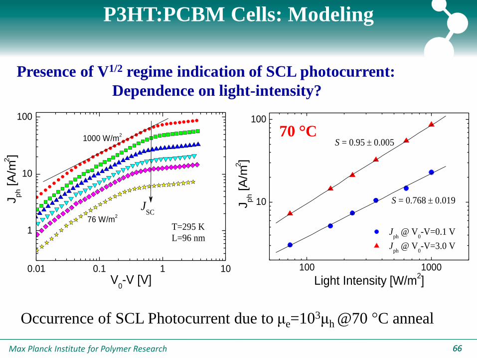
P3HT:PCBM Cells: Modeling
Presence of V1/2 regime indication of SCL photocurrent:
Dependence on light-intensity?
0.01 0.1 1 10
1
10
100
76 W/m2
Jp
h [A
/m2]
V0-V [V]
JSC
T=295 K
L=96 nm
1000 W/m2
100 1000
10
100
S = 0.950.005
Jph
@ V0-V=0.1 V
Jph
@ V0-V=3.0 V
Jp
h [A
/m2]
Light Intensity [W/m2]
S = 0.7680.019
70 °C
Occurrence of SCL Photocurrent due to μe=103μh @70 °C anneal
Max Planck Institute for Polymer Research 6767
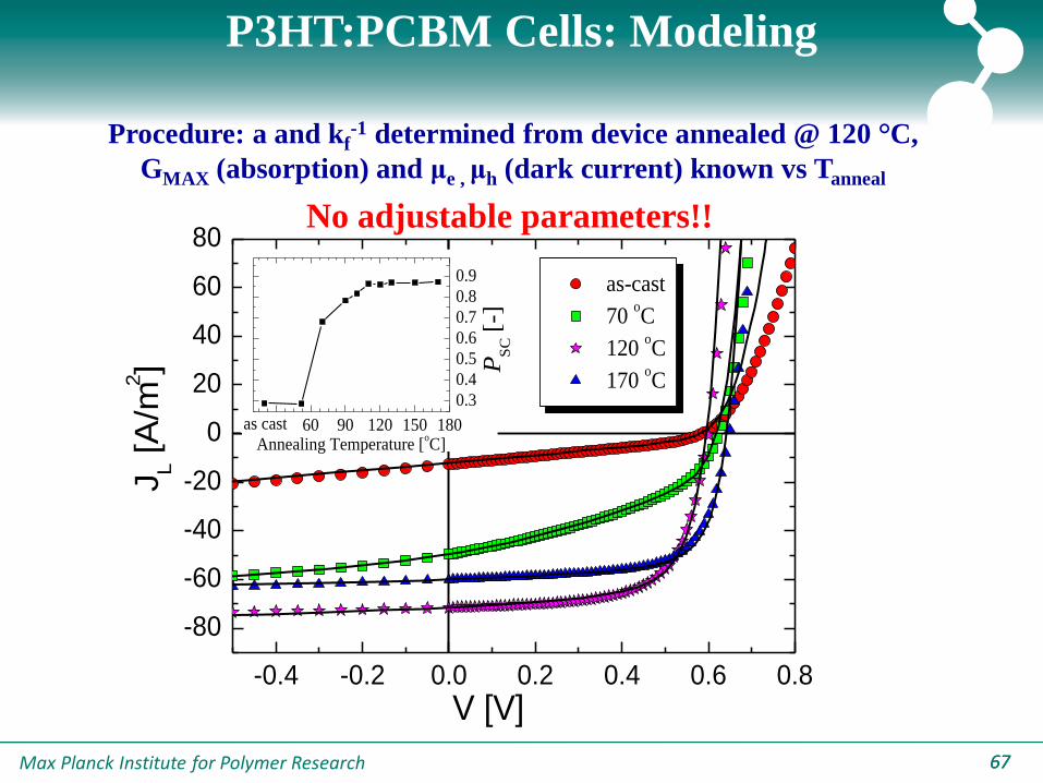
P3HT:PCBM Cells: Modeling
Procedure: a and kf-1 determined from device annealed @ 120 °C,
GMAX (absorption) and μe , μh (dark current) known vs Tanneal
-0.4 -0.2 0.0 0.2 0.4 0.6 0.8
-80
-60
-40
-20
0
20
40
60
80
30 60 90 120 150 180
0.3
0.4
0.5
0.6
0.7
0.8
0.9
PS
C [
-]
Annealing Temperature [oC]
as cast
as-cast
70 oC
120 oC
170 oC
JL [A
/m2]
V [V]
No adjustable parameters!!
Max Planck Institute for Polymer Research 68
|
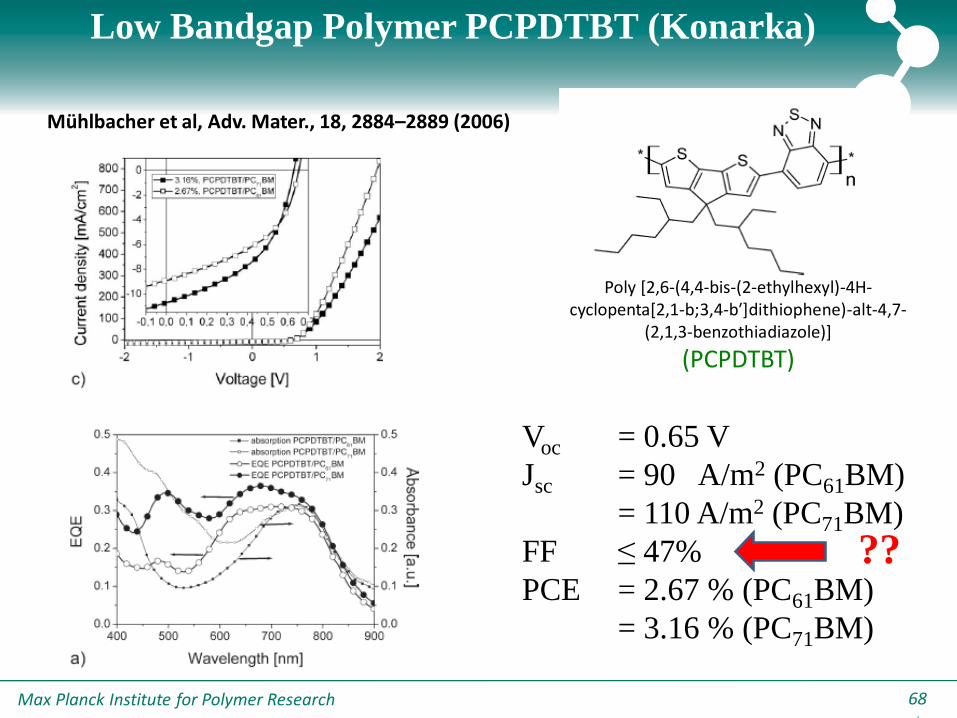
Low Bandgap Polymer PCPDTBT (Konarka)
Voc = 0.65 V
Jsc = 90 A/m2 (PC61BM)
= 110 A/m2 (PC71BM)
FF ≤ 47%
PCE = 2.67 % (PC61BM)
= 3.16 % (PC71BM)
Mühlbacher et al, Adv. Mater., 18, 2884–2889 (2006)
Poly [2,6-(4,4-bis-(2-ethylhexyl)-4H-cyclopenta[2,1-b;3,4-b′]dithiophene)-alt-4,7-
(2,1,3-benzothiadiazole)]
(PCPDTBT)
??
Max Planck Institute for Polymer Research 69
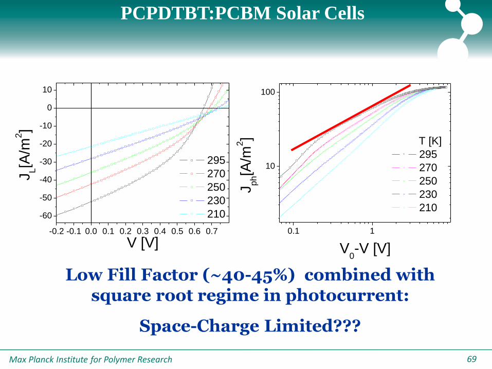
PCPDTBT:PCBM Solar Cells
-0.2 -0.1 0.0 0.1 0.2 0.3 0.4 0.5 0.6 0.7
-60
-50
-40
-30
-20
-10
0
10
295
270
250
230
210
JL[A
/m2]
V [V]
Low Fill Factor (~40-45%) combined with square root regime in photocurrent:
Space-Charge Limited???
0.1 1
10
100
T [K]
295
270
250
230
210
Jp
h[A
/m2]
V0-V [V]
Max Planck Institute for Polymer Research 7070| 70
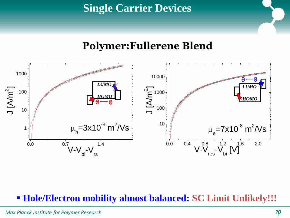
Single Carrier Devices
0.0 0.4 0.8 1.2 1.6 2.0
10
100
1000
10000
J [
A/m
2]
V-Vres
-Vbi [V]
e=7x10
-8 m
2/Vs
0.0 0.7 1.4
1
10
100
1000
J [A
/m2]
V-Vbi-V
rs
h=3x10
-8 m
2/Vs
LUMO
HOMO
LUMO
HOMO
Hole/Electron mobility almost balanced: SC Limit Unlikely!!!
Polymer:Fullerene Blend

Max Planck Institute for Polymer Research 7171
Intensity dependence of Photocurrent:
0.1 1 10
10
100
Jp
h [A
/m2]
V0-V [V]
Jph α V 1/2
Jph α G
Vsat= constant
Vsat
Fingerprint of recombination limited current!!!
Adv. Funct. Mater. 2009, 19, 1106–1111

Max Planck Institute for Polymer Research 7272
|
Square Root Dependence; μτ vs sc limited
Two different origins for a square root dependence of Jph
Space Charge Limited: e >> h
VqGJ hrph
25.0
0
75.0
8
9)(
Jph α V 1/2
Jph α G 3/4
Vsat α G 1/2
V. D. Mihailetchi et al., Phys. Rev. Lett. 94, 126602 (2005)
A. M. Goodman and A. Rose, J. Appl. Phys. 42, 2823 (1971)
μτ-limited: wn,p= E L ; ppnn
VqGJ hhph
0.1 1 10
10
100
Jp
h [A
/m2]
V0-V [V]
Jph α V 1/2
Jph α G
Vsat= constant
Vsat
L1L
V1
G
Max Planck Institute for Polymer Research 7373
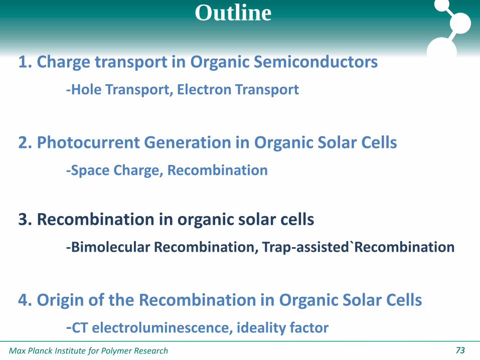
Outline
1. Charge transport in Organic Semiconductors
-Hole Transport, Electron Transport
2. Photocurrent Generation in Organic Solar Cells
-Space Charge, Recombination
3. Recombination in organic solar cells
-Bimolecular Recombination, Trap-assisted`Recombination
4. Origin of the Recombination in Organic Solar Cells
-CT electroluminescence, ideality factor
Max Planck Institute for Polymer Research 7474
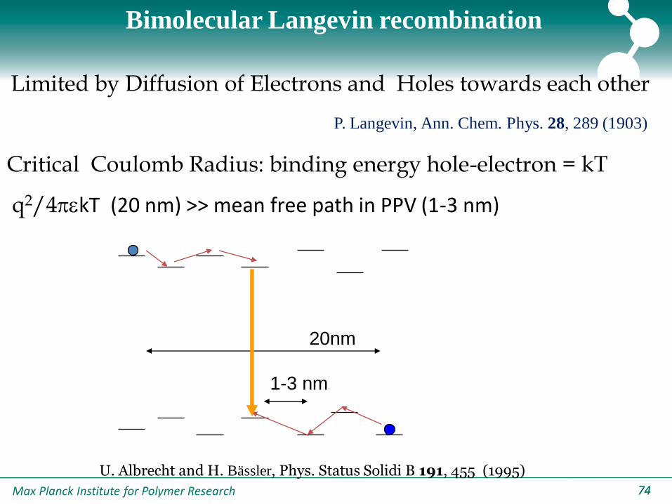
Limited by Diffusion of Electrons and Holes towards each other
Critical Coulomb Radius: binding energy hole-electron = kT
q2/4kT (20 nm) >> mean free path in PPV (1-3 nm)
20nm
1-3 nm
Bimolecular Langevin recombination
U. Albrecht and H. Bässler, Phys. Status Solidi B 191, 455 (1995)
P. Langevin, Ann. Chem. Phys. 28, 289 (1903)

Max Planck Institute for Polymer Research 7575
Study Recombination at Voc !!
Measure Voc ~ Light Intensity!!
Solar cell with bimolecular recombination:
PG
NP
q
kT
q
EV cgap
oc
21
ln
APL 86, 123509 (2005)
E. A. Schiff, Sol. Eng. Mater. Sol. Cells 2003, 78, 567.
How to characterize recombination?

Max Planck Institute for Polymer Research 7676
Light intensity dependence of Voc
Linear dependence of Voc on ln(I) with slope kT/q, n=1 !
1 2 3 4 5
0.65
0.70
0.75
0.80
0.85
0.90
Vo
c [V
]
Ln (intensity) [a.u.]
295 K
250 K
210 K
APL 86, 123509 (2005)
MDMO-PPV:PCBM
Only bimolecular Recombination!!!!!
Max Planck Institute for Polymer Research 7777
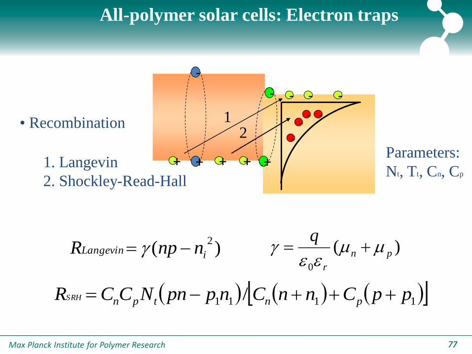
All-polymer solar cells: Electron traps
• Recombination
1. Langevin
2. Shockley-Read-Hall
-
+
-
+
- - -
+ + +
-
--
-12
Parameters:
Nt, Tt, Cn, Cp
1111 / ppCnnCnppnNCCR pntpnSRH
)(2
iLangevin nnpR )(0
pn
r
q
Max Planck Institute for Polymer Research 7878
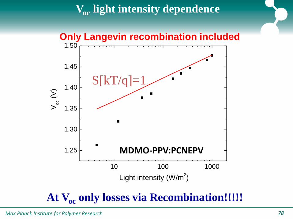
Voc light intensity dependence
10 100 1000
1.25
1.30
1.35
1.40
1.45
1.50
Light intensity (W/m2)
Vo
c (V
)
Only Langevin recombination included
S[kT/q]=1
At Voc only losses via Recombination!!!!!
MDMO-PPV:PCNEPV
Max Planck Institute for Polymer Research 7979
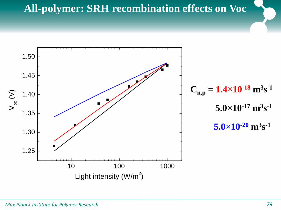
All-polymer: SRH recombination effects on Voc
10 100 1000
1.25
1.30
1.35
1.40
1.45
1.50
Light intensity (W/m2)
Vo
c (
V) Cn,p = 1.4×10⁻¹⁸ m3s-1
5.0×10⁻¹⁷ m3s-1
5.0×10⁻²⁰ m3s-1
Max Planck Institute for Polymer Research 8080
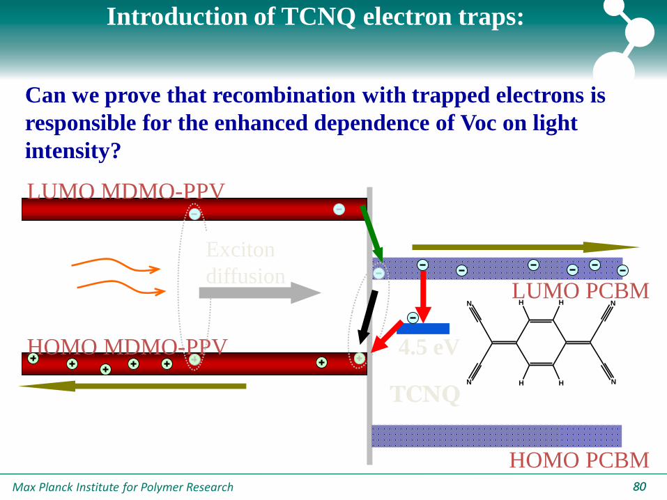
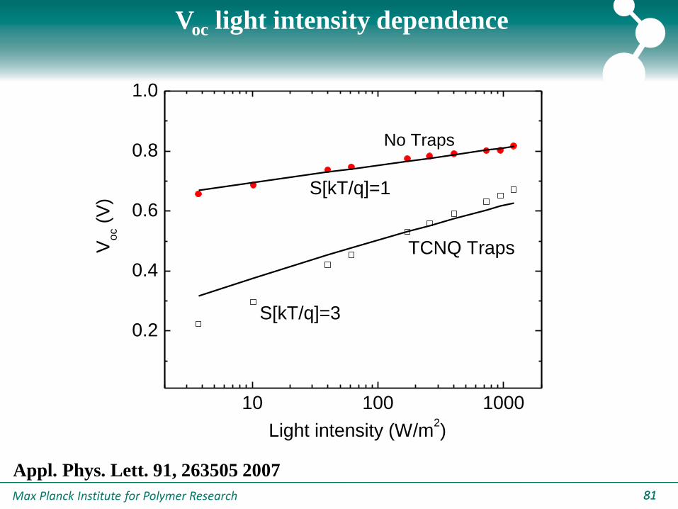
Introduction of TCNQ electron traps:
Can we prove that recombination with trapped electrons is
responsible for the enhanced dependence of Voc on light
intensity?
LUMO MDMO-PPV
LUMO PCBM
HOMO MDMO-PPV
HOMO PCBM
Exciton
diffusionN
N
N
N
H H
H H
4.5 eV
TCNQ
Max Planck Institute for Polymer Research 8181
10 100 1000
0.2
0.4
0.6
0.8
1.0
S[kT/q]=3
Light intensity (W/m2)
Vo
c (
V)
No Traps
S[kT/q]=1
TCNQ Traps
Voc light intensity dependence
Appl. Phys. Lett. 91, 263505 2007
Max Planck Institute for Polymer Research 8282
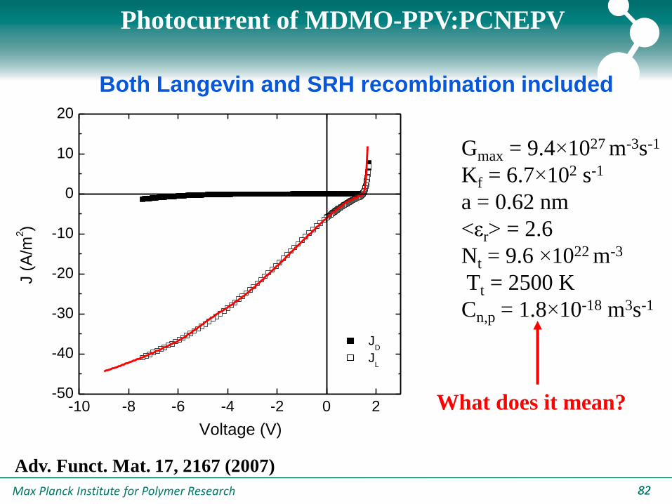
Photocurrent of MDMO-PPV:PCNEPV
-10 -8 -6 -4 -2 0 2-50
-40
-30
-20
-10
0
10
20
Voltage (V)
J (
A/m
2)
JD
JL
Gmax = 9.4×1027 m-3s-1
Kf = 6.7×10² s-1
a = 0.62 nm
<εr> = 2.6
Nt = 9.6 ×10²² m-3
Tt = 2500 K
Cn,p = 1.8×10⁻¹⁸ m3s-1
Both Langevin and SRH recombination included
Adv. Funct. Mat. 17, 2167 (2007)
What does it mean?
Max Planck Institute for Polymer Research 8383
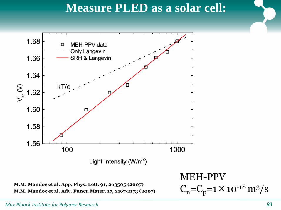
Measure PLED as a solar cell:
MEH-PPVCn=Cp=1×10-18 m3/s
kT/q
M.M. Mandoc et al. App. Phys. Lett. 91, 263505 (2007)
M.M. Mandoc et al. Adv. Funct. Mater. 17, 2167-2173 (2007)
Max Planck Institute for Polymer Research 84
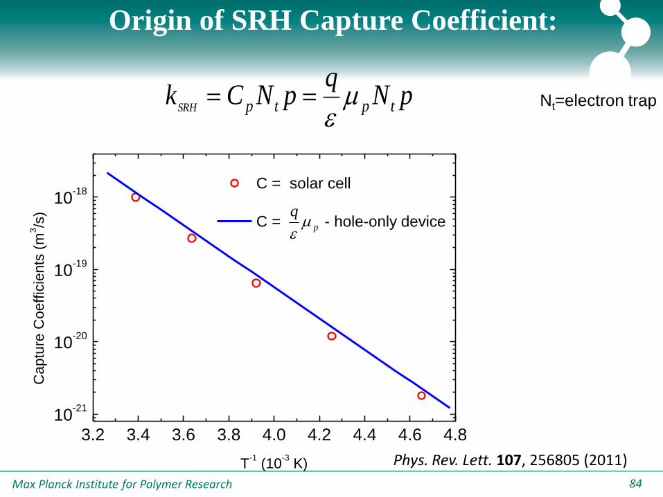
Origin of SRH Capture Coefficient:
3.2 3.4 3.6 3.8 4.0 4.2 4.4 4.6 4.810
-21
10-20
10-19
10-18
p
q
C = solar cell
C = - hole-only device
Ca
ptu
re C
oeff
icie
nts
(m
3/s
)
T-1 (10
-3 K)
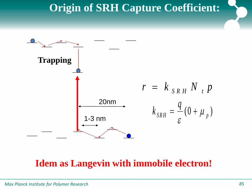
pNq
pNCk tptpSRH
Nt=electron trap
Phys. Rev. Lett. 107, 256805 (2011)
Max Planck Institute for Polymer Research 85
Origin of SRH Capture Coefficient:
20nm
1-3 nm
pNkr tS R H
)0( pS R H
qk
Trapping
Idem as Langevin with immobile electron!
Max Planck Institute for Polymer Research 8686
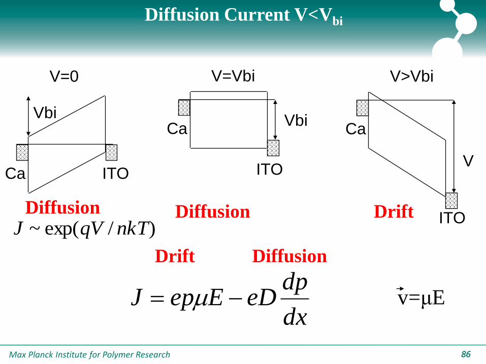
V=0
Ca ITO
Vbi
V=Vbi
CaVbi
ITO
V>Vbi
Ca
V
ITO
Diffusion Current V<Vbi
Drift Diffusion
DriftDiffusion Diffusion
dx
dpeDEepJ
)/exp(~ nkTqVJ
v=μE
Max Planck Institute for Polymer Research 87
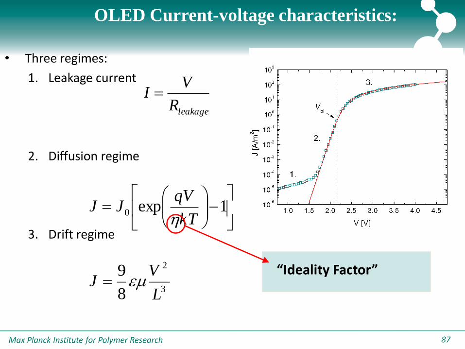
OLED Current-voltage characteristics:
• Three regimes:
1. Leakage current
2. Diffusion regime
3. Drift regime
1.0 1.5 2.0 2.5 3.0 3.5 4.0 4.510
-6
10-5
10-4
10-3
10-2
10-1
100
101
102
103
J [
A/m
2]
V [V]
1.
2.
3.
Vbi
1exp0
kT
qVJJ
h
3
2
8
9
L
VJ
leakageR
VI
“Ideality Factor”

Max Planck Institute for Polymer Research 8888
Origin of Ideality Factor?
• Ideality factor equals 2 in the case of trap-assisted
recombination in a classical p-n junction
1
2exp0
kT
qVJJ
C. T. Sah et al., Proc. IRE 45, 1228 (1957)

Max Planck Institute for Polymer Research 89
Super Yellow PPV LED
• The ideality factor for a Super
Yellow LED was determined to
have a value of 2 at room
temperature.
• This corresponds to SRH
recombination from trapping
sites:
1
2exp0
kT
qVJJ
1
ln
V
J
q
kTh

Max Planck Institute for Polymer Research 9090
White OLEDs: Emissive SRH recombination?
• Trap-assisted recombination in conventional polymers appears
to be non-radiative.
• In a white emitting polymer, red dyes in the blue backbone
function as emissive traps.
HOMO
LUMO
Max Planck Institute for Polymer Research 91
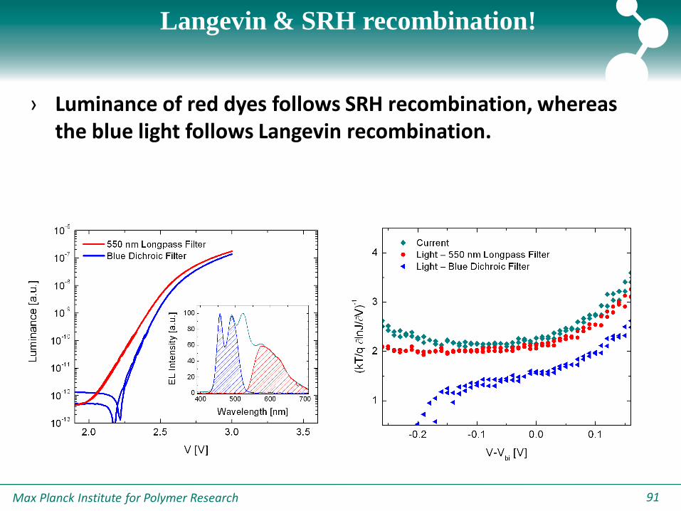
Langevin & SRH recombination!
-0.2 -0.1 0.0 0.1
1
2
3
4 Current
Light – 550 nm Longpass Filter
Light – Blue Dichroic Filter
(kT
/q
lnJ/
V)-1
V-Vbi [V]
2.0 2.5 3.0 3.510
-13
10-12
10-11
10-10
10-9
10-8
10-7
10-6
400 500 600 7000
20
40
60
80
100
EL
Inte
nsity [a
.u.]
Wavelength [nm]
550 nm Longpass Filter
Blue Dichroic Filter
Lu
min
an
ce
[a
.u.]
V [V]
› Luminance of red dyes follows SRH recombination, whereas the blue light follows Langevin recombination.
Max Planck Institute for Polymer Research 9292
Outline
1. Charge transport in Organic Semiconductors
-Hole Transport, Electron Transport
2. Photocurrent Generation in Organic Solar Cells
-Space Charge, Recombination
3. Recombination in organic solar cells
-Bimolecular Recombination, Trap-assisted Recombination
4. Origin of the Recombination in Organic Solar Cells
-CT electroluminescence, ideality factor
Max Planck Institute for Polymer Research 9393
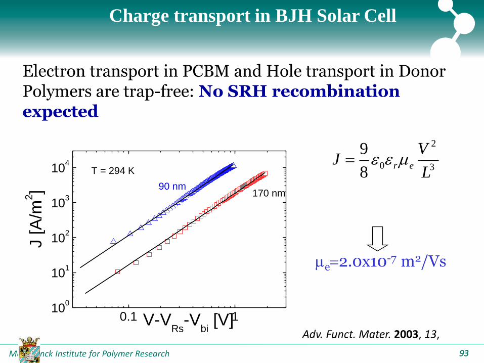
Charge transport in BJH Solar Cell
0.1 110
0
101
102
103
104
T = 294 K
170 nm90 nm
J [
A/m
2]
V-VRs
-Vbi [V]
3
2
08
9
L
VJ er
e2.0x10-7 m2/Vs
Adv. Funct. Mater. 2003, 13,
Electron transport in PCBM and Hole transport in Donor Polymers are trap-free: No SRH recombination expected
Max Planck Institute for Polymer Research 94
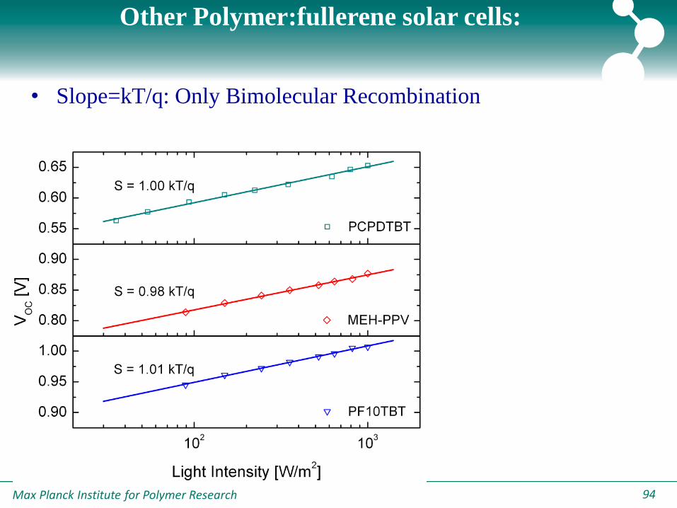
• Slope=kT/q: Only Bimolecular Recombination
Other Polymer:fullerene solar cells:
Max Planck Institute for Polymer Research 95
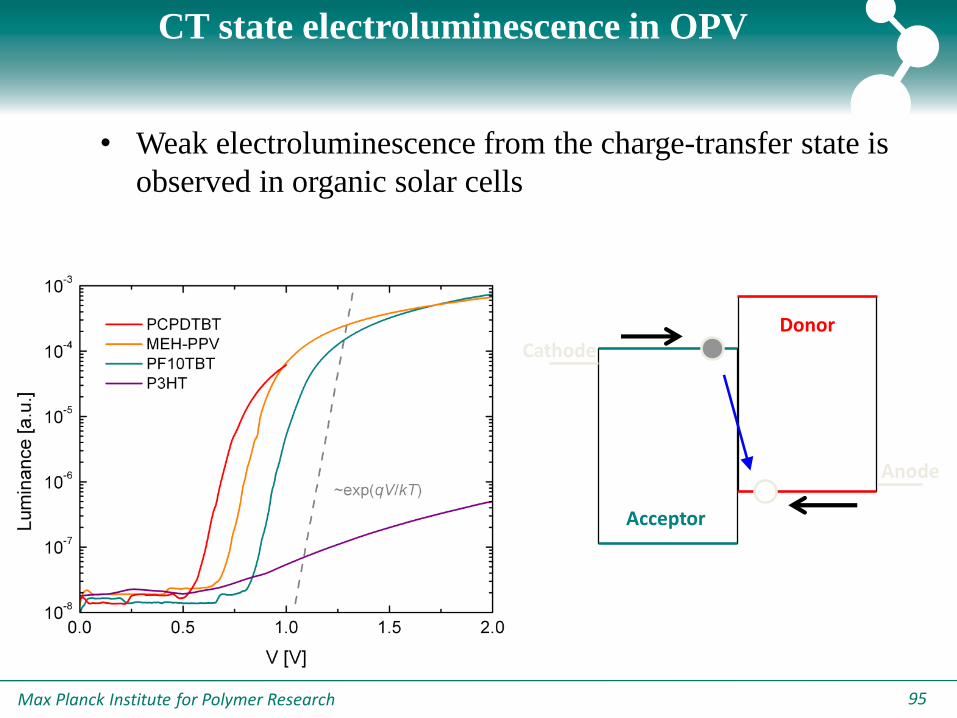
CT state electroluminescence in OPV
• Weak electroluminescence from the charge-transfer state is
observed in organic solar cells
Cathode
Anode
Acceptor
Donor
Max Planck Institute for Polymer Research 96
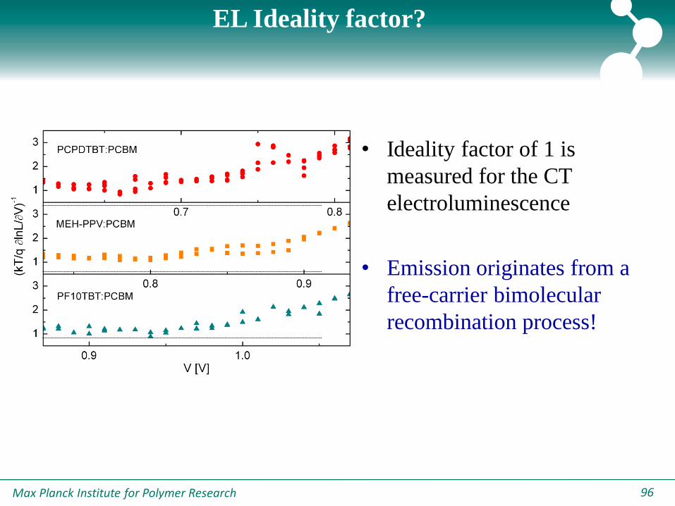
EL Ideality factor?
• Ideality factor of 1 is
measured for the CT
electroluminescence
• Emission originates from a
free-carrier bimolecular
recombination process!
Max Planck Institute for Polymer Research 97
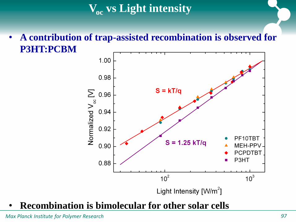
Voc vs Light intensity
• A contribution of trap-assisted recombination is observed for
P3HT:PCBM
• Recombination is bimolecular for other solar cells
Max Planck Institute for Polymer Research 98
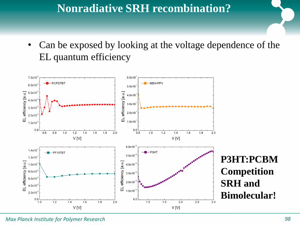
Nonradiative SRH recombination?
• Can be exposed by looking at the voltage dependence of the
EL quantum efficiency
P3HT:PCBM
Competition
SRH and
Bimolecular!
Max Planck Institute for Polymer Research 9999
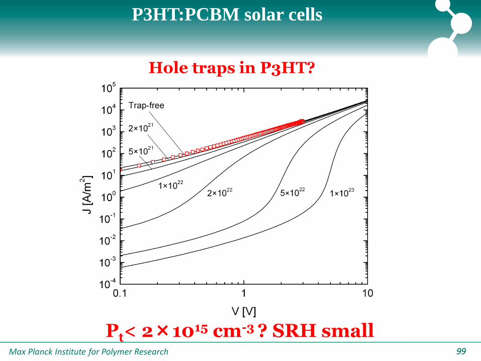
P3HT:PCBM solar cells
Pt< 2×1015 cm-3 ? SRH small
Hole traps in P3HT?
Max Planck Institute for Polymer Research 100100
P3HT:PCBM solar cells
In P3HT:PCBM solar cells the Langevin recombination
is strongly reduced ~103 (CELIV)
Pivrikas, Osterbacka, Juska et al., Phys. Rev. Lett. 94, 176806 (2005)
Two dimensional Langevin recombination in the
lamellar structure of RR-P3HT
Juska, Osterbacka et al., Appl. Phys. Lett. 95, 013303 (2009)
Max Planck Institute for Polymer Research 101101
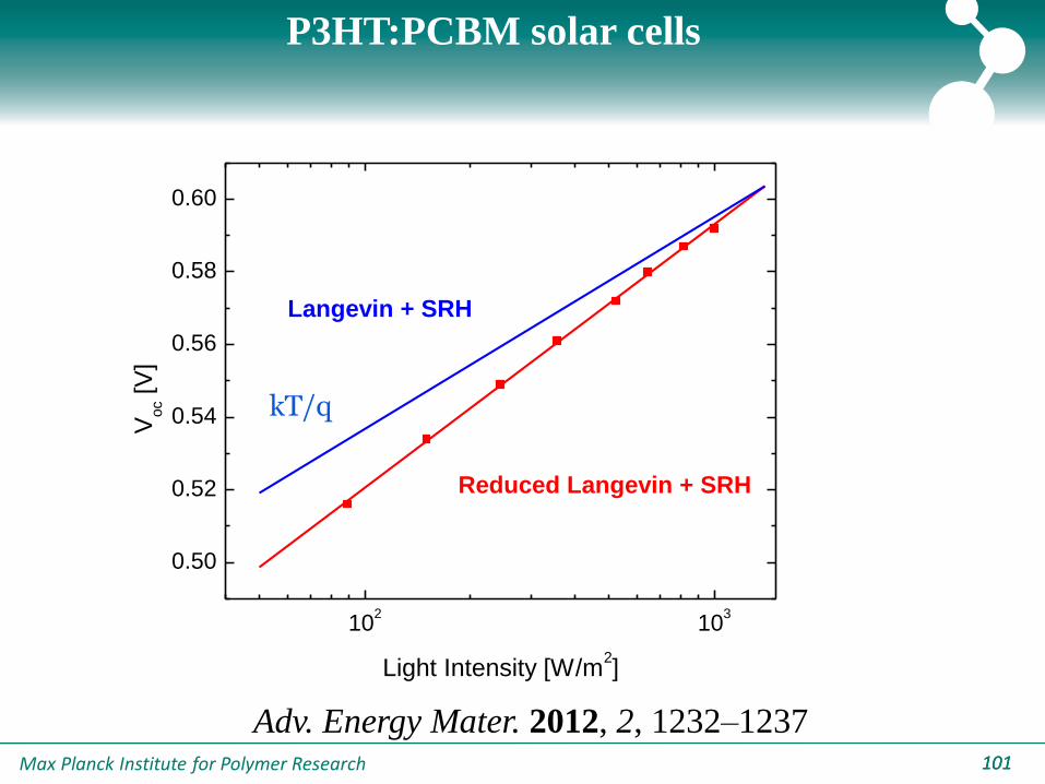
P3HT:PCBM solar cells
102
103
0.50
0.52
0.54
0.56
0.58
0.60
Reduced Langevin + SRH
V
oc [
V]
Light Intensity [W/m2]
Langevin + SRH
kT/q
Adv. Energy Mater. 2012, 2, 1232–1237
Max Planck Institute for Polymer Research 102
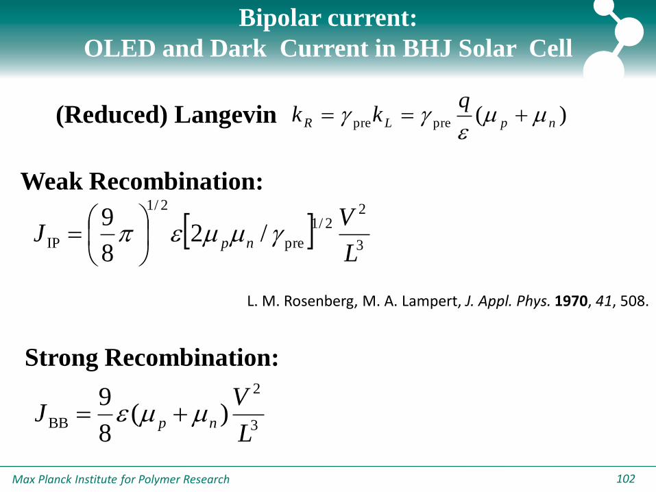
Bipolar current:
OLED and Dark Current in BHJ Solar Cell
Weak Recombination:
Strong Recombination:
3
22/1
pre
2/1
IP /28
9
L
VJ np
3
2
BB )(8
9
L
VJ np
L. M. Rosenberg, M. A. Lampert, J. Appl. Phys. 1970, 41, 508.
)(prepre npLR
qkk
(Reduced) Langevin
Max Planck Institute for Polymer Research 103
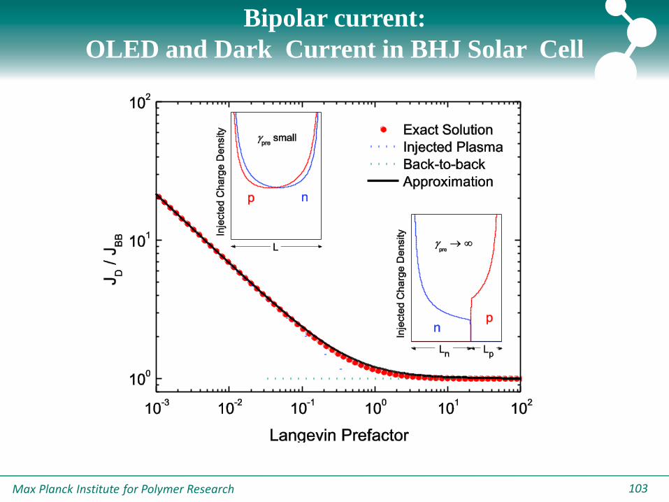
Bipolar current:
OLED and Dark Current in BHJ Solar Cell
Max Planck Institute for Polymer Research 104
Bipolar current:
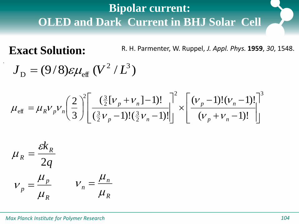
OLED and Dark Current in BHJ Solar Cell
Exact Solution: R. H. Parmenter, W. Ruppel, J. Appl. Phys. 1959, 30, 1548.
)/()8/9( 32
effD LVJ
32
23
23
232
eff)!1(
)!1()!1(
)!1()!1(
)!1][(
3
2
np
np
np
np
npRnn
nn
nn
nnnn
q
kRR
2
R
p
p
n
R
nn
n
.
Max Planck Institute for Polymer Research 105
2
IP
2
BBD JJJ
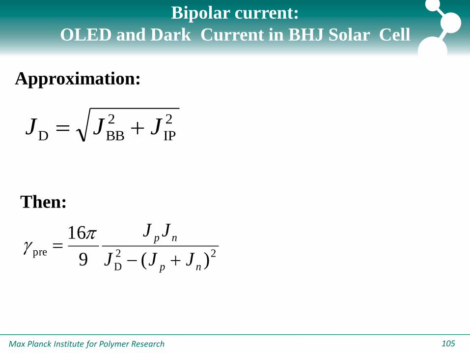
Bipolar current:
OLED and Dark Current in BHJ Solar Cell
Approximation:
Then:
22
D
pre)(9
16
np
np
JJJ
JJ
Max Planck Institute for Polymer Research 106
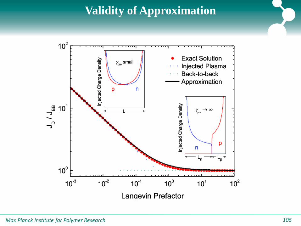
Validity of Approximation
Max Planck Institute for Polymer Research 107
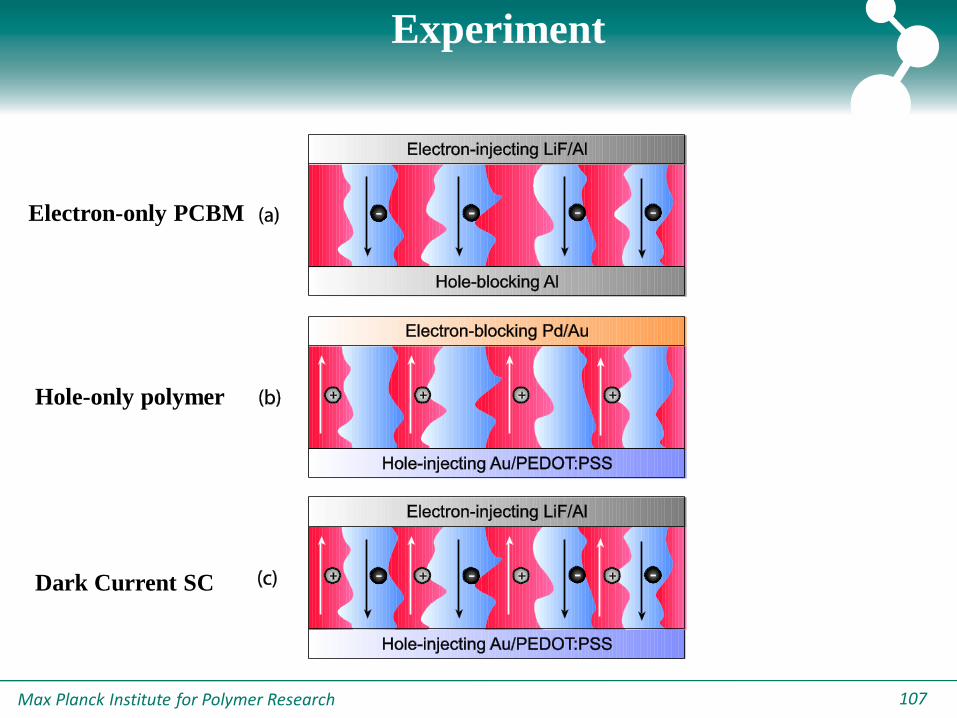
Experiment
Electron-only PCBM
Hole-only polymer
Dark Current SC
Max Planck Institute for Polymer Research 108
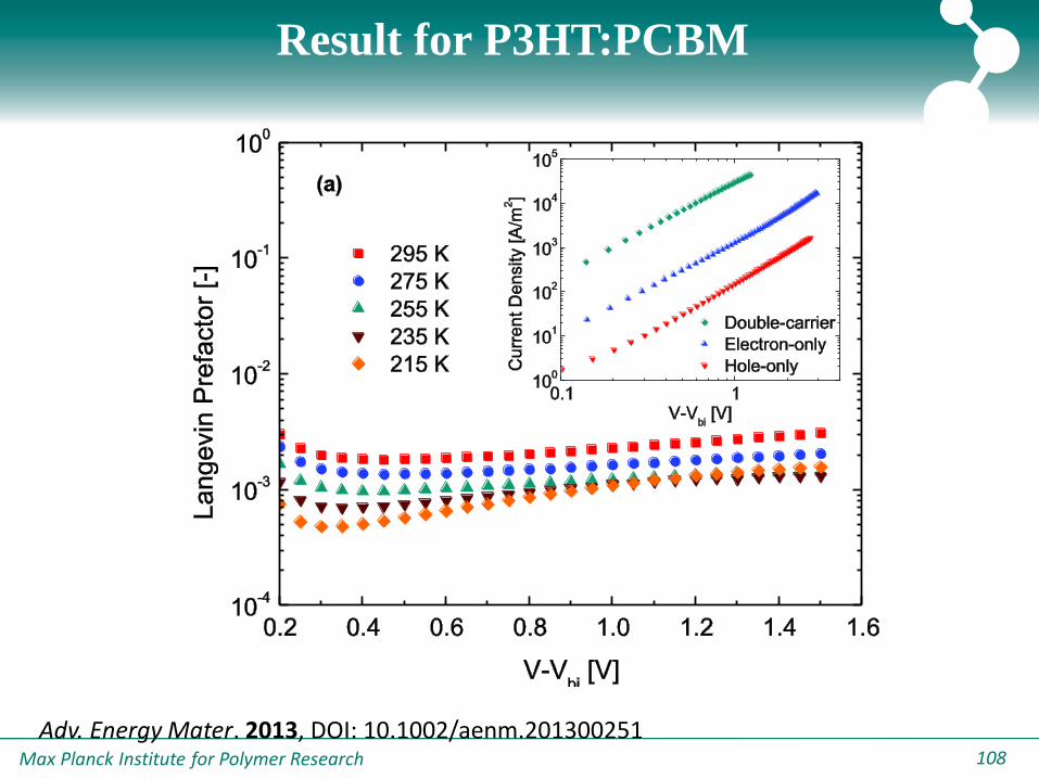
Result for P3HT:PCBM
Adv. Energy Mater. 2013, DOI: 10.1002/aenm.201300251
Max Planck Institute for Polymer Research 109
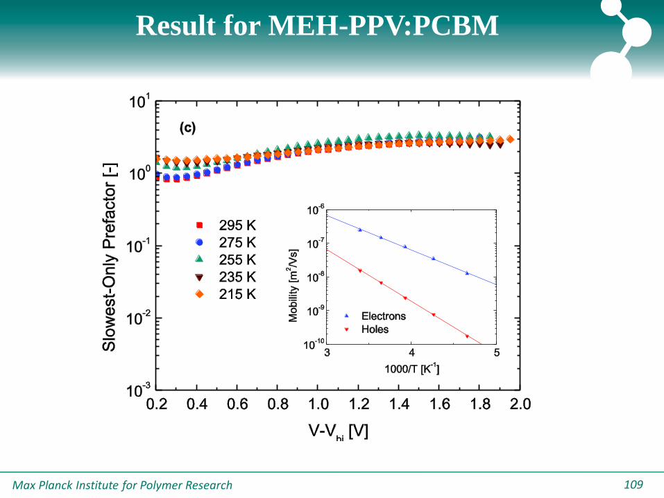
Result for MEH-PPV:PCBM
Max Planck Institute for Polymer Research 110
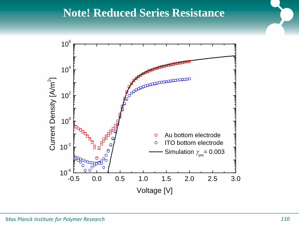
-0.5 0.0 0.5 1.0 1.5 2.0 2.5 3.010
-4
10-2
100
102
104
106
Au bottom electrode
ITO bottom electrode
Simulation pre
= 0.003
Curr
ent
Density [
A/m
2]
Voltage [V]
Note! Reduced Series Resistance
Max Planck Institute for Polymer Research 111111
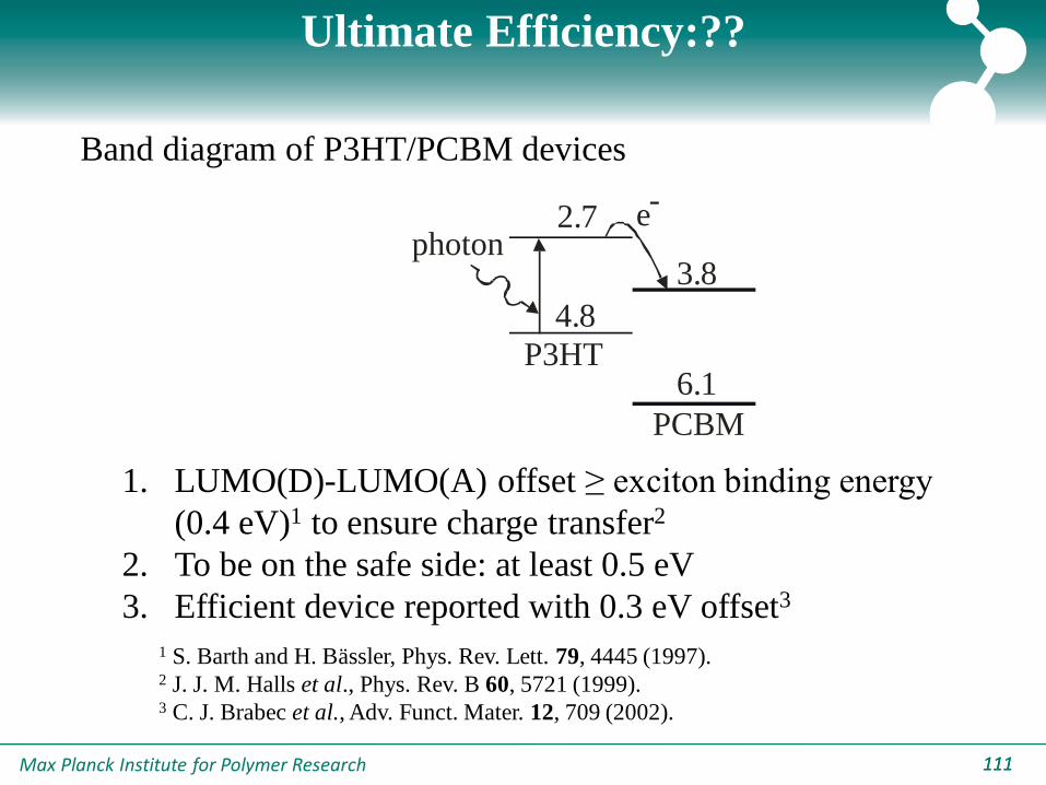
Ultimate Efficiency:??
P3HT
PCBM
ephoton
3.8
4.8
2.7
6.1
-
Band diagram of P3HT/PCBM devices
1 S. Barth and H. Bässler, Phys. Rev. Lett. 79, 4445 (1997).2 J. J. M. Halls et al., Phys. Rev. B 60, 5721 (1999).3 C. J. Brabec et al., Adv. Funct. Mater. 12, 709 (2002).
1. LUMO(D)-LUMO(A) offset ≥ exciton binding energy
(0.4 eV)1 to ensure charge transfer2
2. To be on the safe side: at least 0.5 eV
3. Efficient device reported with 0.3 eV offset3

Max Planck Institute for Polymer Research 112112
400 600 800 10000
1
2
3
4
P3HT/PCBM film
P3HT part red shifted
Ab
so
rba
nce
[a
.u.]
Wavelength [nm]
Optimization: lowering Egap
1. In order to mimic absorption spectrum of low band gap
polymer, shift P3HT part of spectrum down in energy
2. Recalculate generation rate of charge carriers
Max Planck Institute for Polymer Research 113113
1.5 1.6 1.7 1.8 1.9 2.0 2.13
4
5
6
7
Donor
Acceptor
4.8
6.1
3.8
Eff
icie
ncy [
%]
Polymer bandgap [eV]
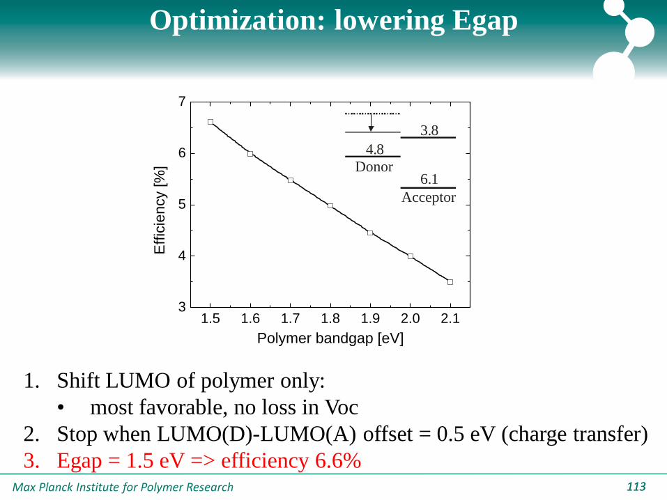
Optimization: lowering Egap
1. Shift LUMO of polymer only:
• most favorable, no loss in Voc
2. Stop when LUMO(D)-LUMO(A) offset = 0.5 eV (charge transfer)
3. Egap = 1.5 eV => efficiency 6.6%
Max Planck Institute for Polymer Research 114114
0.5 0.6 0.7 0.8 0.9 1.0 1.13
4
5
6
7
8
9
Donor
Acceptor
4.8
2.7
6.1
Effic
iency [%
]
LUMO(A) - LUMO(D) [eV]
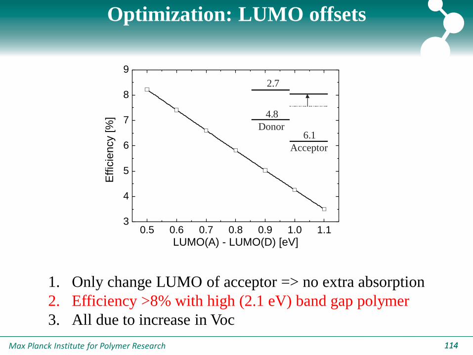
Optimization: LUMO offsets
1. Only change LUMO of acceptor => no extra absorption
2. Efficiency >8% with high (2.1 eV) band gap polymer
3. All due to increase in Voc

Max Planck Institute for Polymer Research 115115
1.5 1.6 1.7 1.8 1.9 2.0 2.16
7
8
9
Donor
Acceptor
4.8
6.1
Effic
iency [%
]
Polymer bandgap [eV]
Optimization: combined effect
1. Keep LUMO(D)-LUMO(A) at 0.5 eV, while decreasing
band gap of polymer
2. Optimal band gap 1.8-2.1 eV, broad maximum
3. Low band gap less efficient due to low Voc

Max Planck Institute for Polymer Research 116116
100 150 200 250 300
6
8
10
12
h=e
h as is
Effic
iency [%
]
Active layer thickness [nm]
Optimization: high p
1. Higher hole mob. allows for thicker films => more absorption
2. Recalculate generation rate from absorption coefficients, taking
reflection at cathode into account
3. Ultimate efficiency 11%
Max Planck Institute for Polymer Research 117117
Conclusions
• Imbalanced transport and strong recombination
lead to a square-root dependence of the
photocurrent, FF~0.4
• Nature of recombination can be identified from
charge-transfer state electroluminescence
– CT-state emission is of bimolecular origin
– Weak trap-assisted recombination is present in
P3HT:PCBM solar cells
Max Planck Institute for Polymer Research 118118
Valentin Mihaeletchi
Magda Mandoc
Jan Anton Koster
Gert-Jan Wetzelaer
Martijn Kuik
Herman Nicolai
Bert de Boer†
Dago de Leeuw
Kees HUmmelen
Rene Janssen
Acknowledgement:
MEPOS Group RuG

Max Planck Institute for Polymer Research 119119
Thank you for your attention!!!