Characterization with TEM - folk.uio.nofolk.uio.no/.../2014/TEMpresPDF.pdf · Characterization with...
25
Characterization with TEM - Introduction to electron microscopy, diffraction and nano-imaging Sindre W. Langfeldt
Transcript of Characterization with TEM - folk.uio.nofolk.uio.no/.../2014/TEMpresPDF.pdf · Characterization with...
Characterization with TEM
- Introduction to electron microscopy, diffraction and nano-imaging
Sindre W. Langfeldt

Introduction
• TEM microscope
• Aspects of electron interaction
• Diffraction
• Characterization in TEM
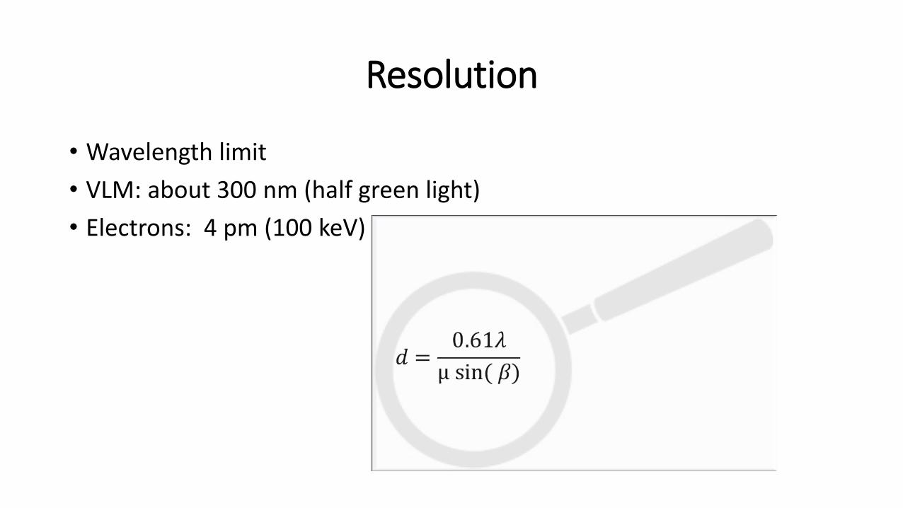
Resolution
• Wavelength limit
• VLM: about 300 nm (half green light)
• Electrons: 4 pm (100 keV)

JEOL 2000FX Wehnelt cylinder Filament Anode
Electron gun 1. and 2. beam deflectors
1.and 2. condenser lens Condenser aperture Condenser lens stigmator coils Condenser lens 1. and 2. beam deflector
Condenser mini-lens Objective lens pole piece Objective aperture Objective lens pole piece Objective lens stigmators 1.Image shift coils Objective mini-lens coils (low mag) 2. Image shift coils 1., 2.and 3. Intermediate lens
Projector lens beam deflectors Projector lens Screen
Mini-lens screws
Specimen
Intermediate lens shifting screws Projector lens shifting screws
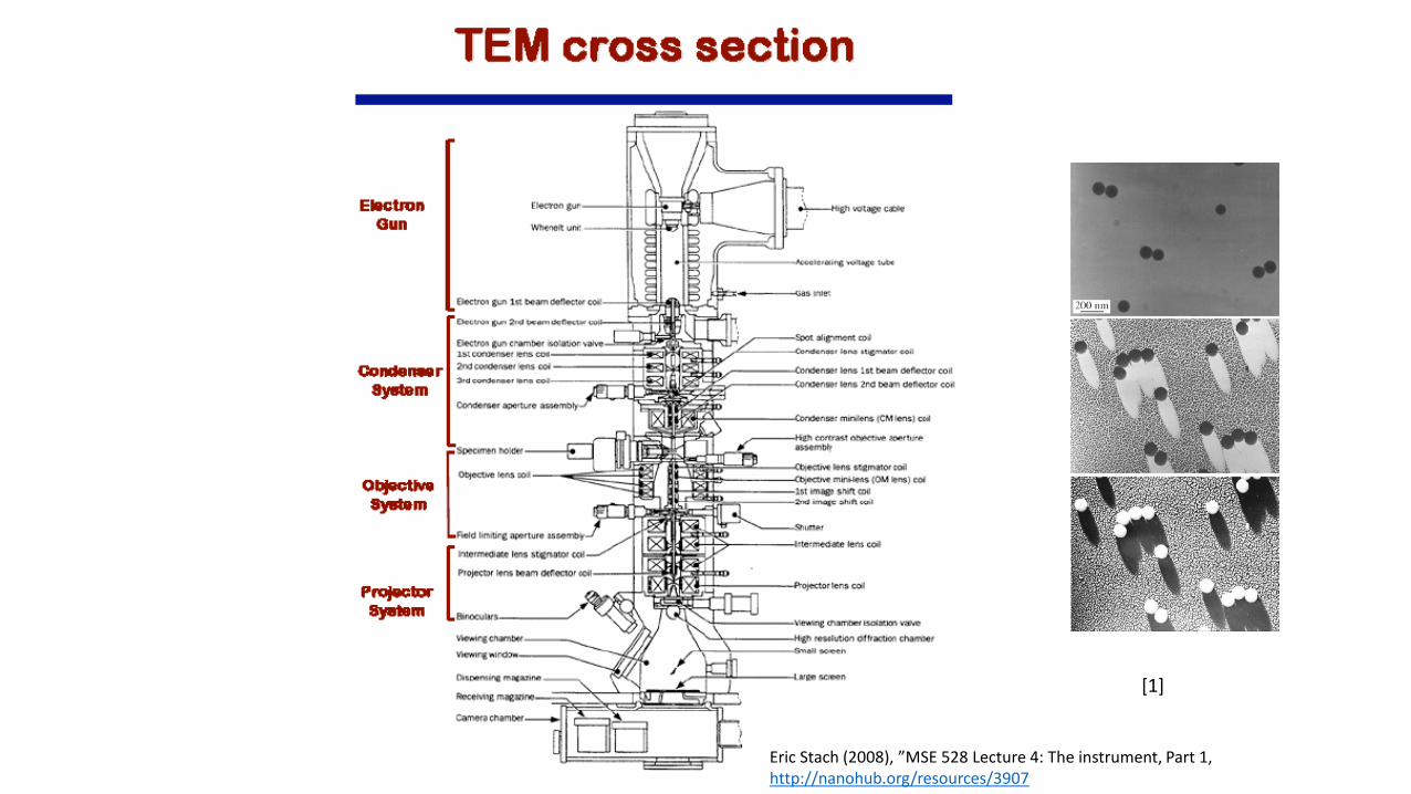
Eric Stach (2008), ”MSE 528 Lecture 4: The instrument, Part 1, http://nanohub.org/resources/3907
[1]

The electron source
• Two types of emission sources • Thermionic emission
• W or LaB6
• Field emission • W ZnO/W
Cold FEG Schottky FEG

Field emission
• Current density: Fowler-Norheim
Maxwell-Boltzmann energy distribution
for all sources

Electron lenses
• Electrostatic • Require high voltage - insulation problems
• Not used as imaging lenses, but are used in modern monochromators or deflectors
• Magnetic • Can be made more accurately
• Shorter focal length
F= -eE
F= -e(v x B)
Any axially symmetrical electric or magnetic field has the properties of an ideal lens for paraxial rays of charged particles.

General features of magnetic lenses
• Focuses near-axis electron rays with the same accuracy as a glass lens focuses near axis light rays.
• Same aberrations as glass lenses.
• Converging lenses.
• The bore of the pole pieces in an objective lens is about 4 mm or less.
• A single magnetic lens rotates the image relative to the object.
• Focal length can be varied by changing the field between the pole pieces (changing magnification).
http://www.matter.org.uk/tem/lenses/electromagnetic_lenses.htm
Bore
Soft Fe pole piece
gap
Cu coil
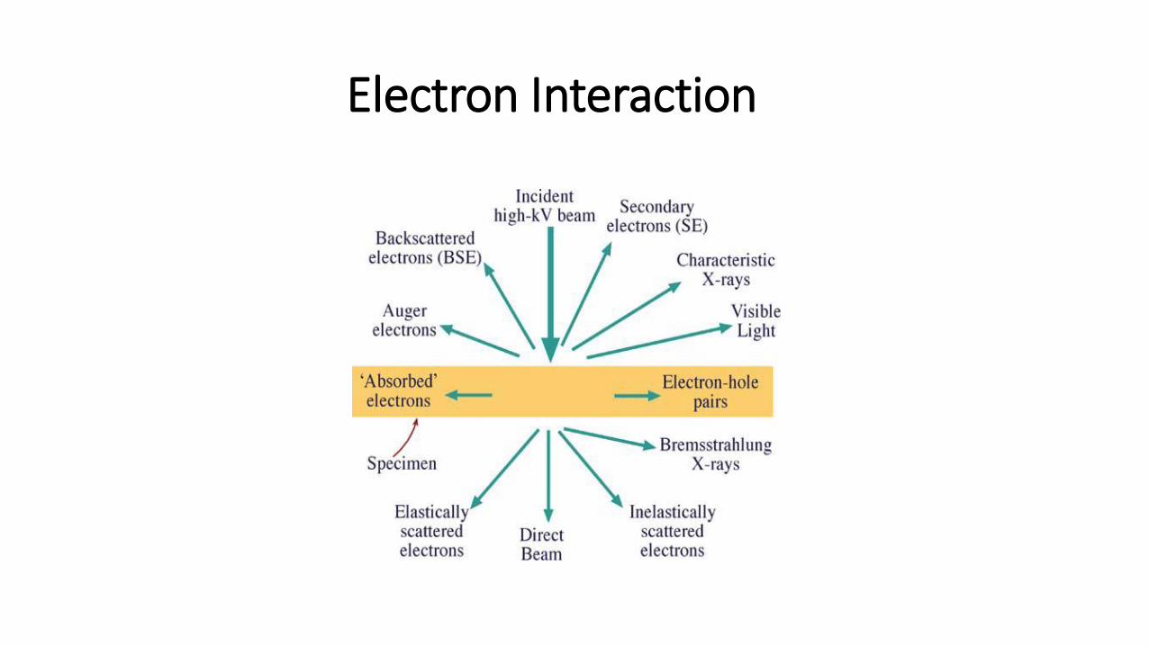
Electron Interaction
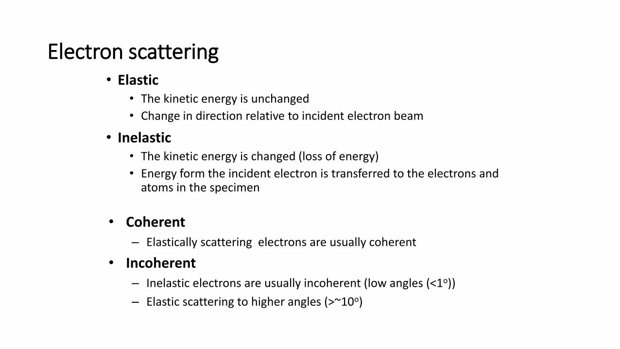
Electron scattering • Elastic
• The kinetic energy is unchanged
• Change in direction relative to incident electron beam
• Inelastic • The kinetic energy is changed (loss of energy)
• Energy form the incident electron is transferred to the electrons and atoms in the specimen
• Coherent – Elastically scattering electrons are usually coherent
• Incoherent – Inelastic electrons are usually incoherent (low angles (<1o))
– Elastic scattering to higher angles (>~10o)
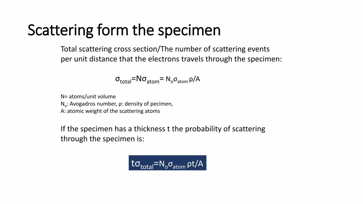
Scattering form the specimen Total scattering cross section/The number of scattering events per unit distance that the electrons travels through the specimen:
σtotal=Nσatom= Noσatom ρ/A
N= atoms/unit volume No: Avogadros number, ρ: density of pecimen, A: atomic weight of the scattering atoms
If the specimen has a thickness t the probability of scattering through the specimen is:
tσtotal=Noσatom ρt/A

Mean free path λ
λ = 1/σtotal = A/Noρσatom
The mean free path for a scattering process is the average distance travelled by the primary particle between scattering events.
Material 10kV 20kV
30kV
40kV
50kV
100kV
200kV
1000kV
C (6) 5.5 22 49 89 140 550 2200 55000
Al (13) 1.8 7.4 17 29 46 180 740 18000
Fe (26) 0.15 0.6 2.9 5.2 8.2 30 130 3000
Ag (47) 0.15 0.6 1.3 2.3 3.6 15 60 1500
Pb (82) 0.08 0.34 0.76 1.4 2.1 8 34 800
U (92) 0.05 0.19 0.42 0.75 1.2 5 19 500
(Mean free path (nm) as a function of acceleration voltage for elastic electron for scattering more than 2o events.)

Lattice properties of crystals • The crystal structure is described by specifying a repeating
element and its translational periodicity • The repeating element (usually consisting of many atoms) is replaced by a lattice point
and all lattice points have the same atomic environments.
Repeating element in the example
Crystals have a periodic internal structure
Lattice point
Point lattice

Point lattice Repeting element Unit cell
Atoms and lattice points situated on corners, faces and edges are shared with neighbouring cells.
BCC
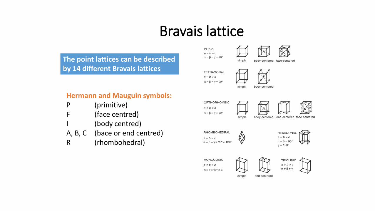
Bravais lattice
The point lattices can be described by 14 different Bravais lattices
Hermann and Mauguin symbols: P (primitive) F (face centred) I (body centred) A, B, C (bace or end centred) R (rhombohedral)
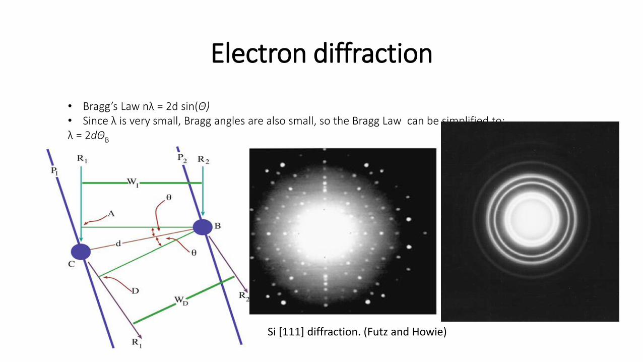
Electron diffraction
• Bragg’s Law nλ = 2d sin(Θ) • Since λ is very small, Bragg angles are also small, so the Bragg Law can be simplified to: λ = 2dΘB
Si [111] diffraction. (Futz and Howie)

Diffraction
• Thin sample
• Transmitted
• Coulomb interaction
• Diffraction pattern
http://nanohub.org/resources/4640/supportingdocs

Real or Reciprocal Space?
• Comparing images is equally good
• Convert images with fast Fourier transformation (FFT)
• Real space: «scattering intensites», some resolution lost with FFT
• Realspace is more intuitive, easy to interprate.
50 nm
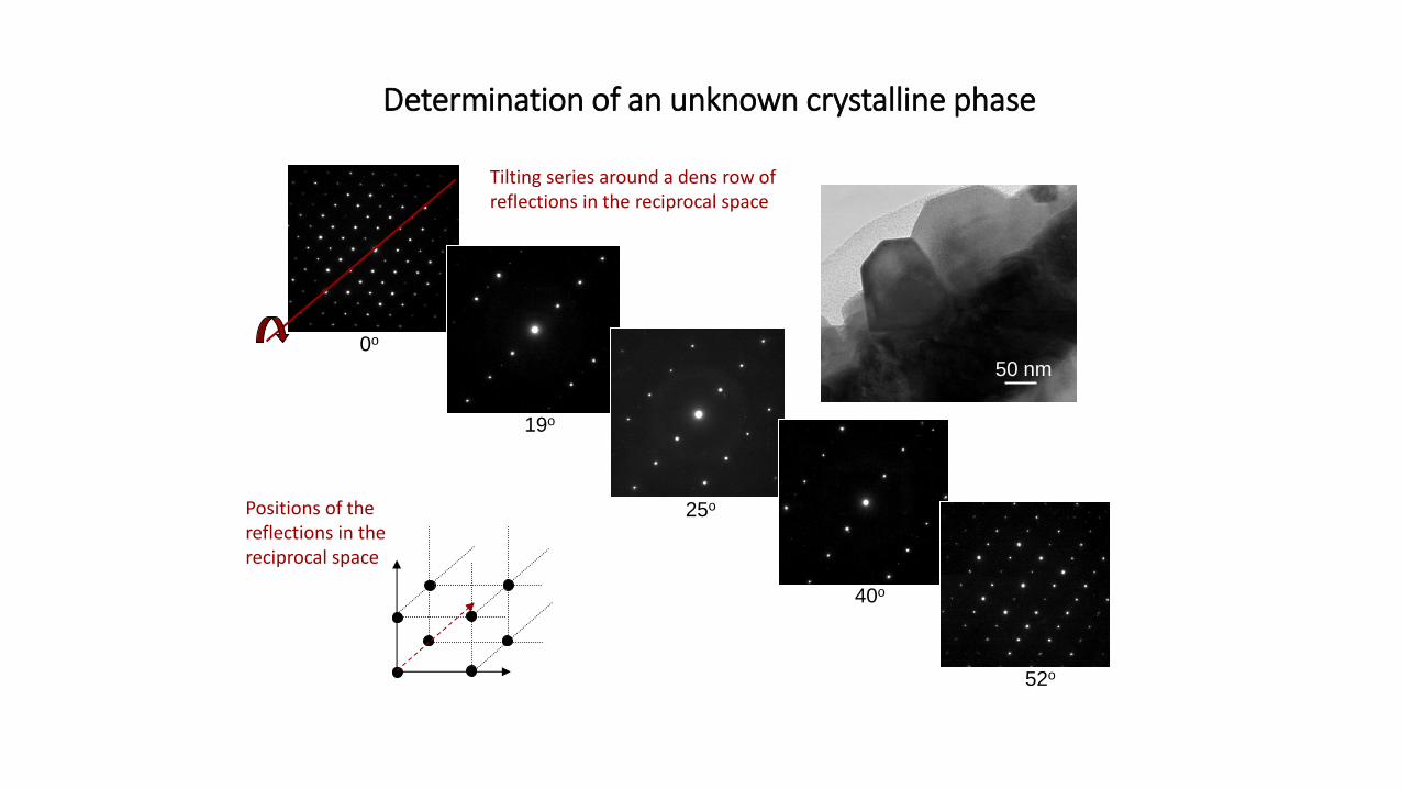
Tilting series around a dens row of reflections in the reciprocal space
0o
19o
25o
40o
52o
Positions of the reflections in the reciprocal space
Determination of an unknown crystalline phase
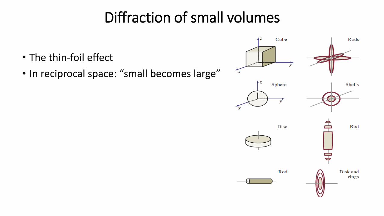
Diffraction of small volumes
• The thin-foil effect
• In reciprocal space: “small becomes large”

• XEDS
• EELS
From Williams and Carter (2009)
Characterization methods
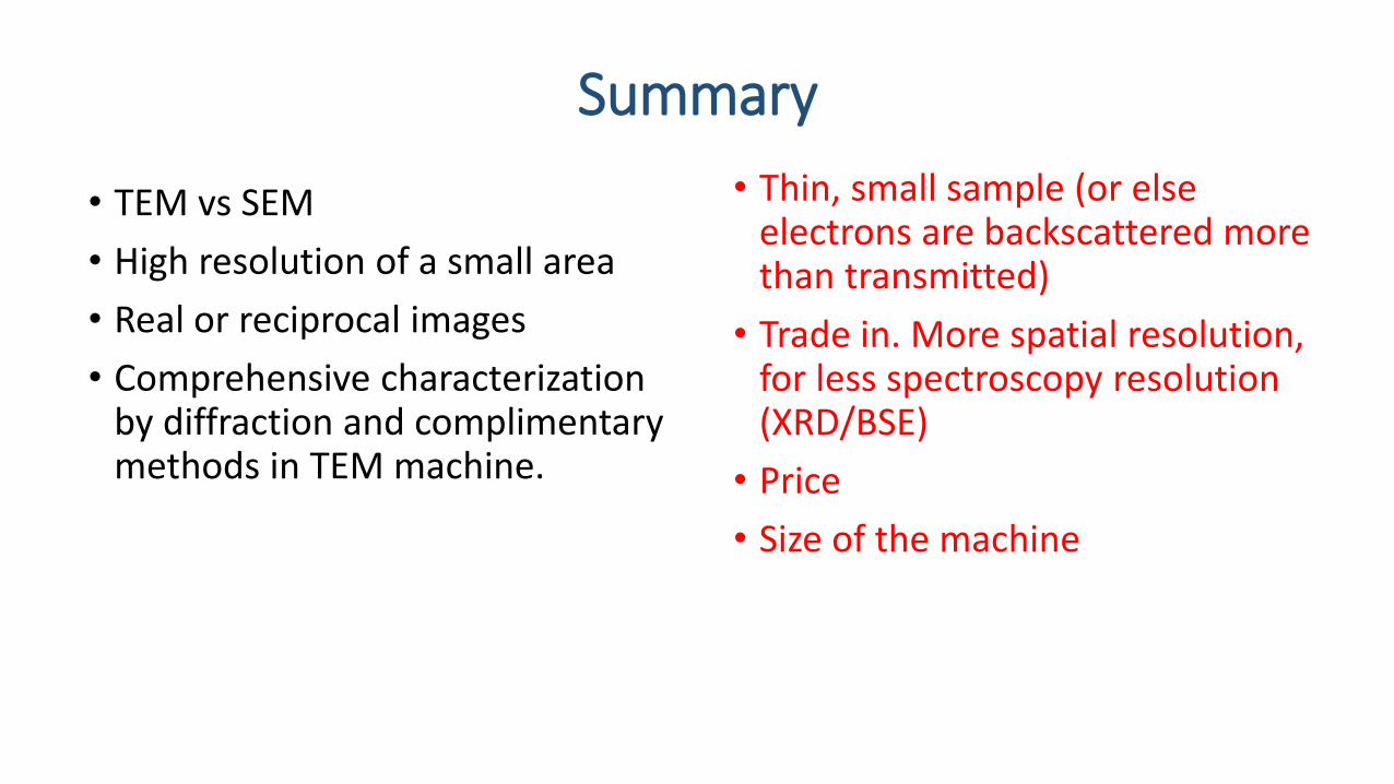
Summary
• Thin, small sample (or else electrons are backscattered more than transmitted)
• Trade in. More spatial resolution, for less spectroscopy resolution (XRD/BSE)
• Price
• Size of the machine
• TEM vs SEM
• High resolution of a small area
• Real or reciprocal images
• Comprehensive characterization by diffraction and complimentary methods in TEM machine.

Refrences
• [1] Transmission Electron Microscopy A Textbook for Materials Science. David B. Williams, C. Barry Carter.
Web Pages:
• http://nanohub.org/members/23993/usage
• http://www.matter.org.uk/diffraction/
• [2] Fultz and Howe, TEM and
Diffractometry of Materials

Thank You!