Characterization Summary Report - a passion for … concept for the HFBR used a new approach in...
61
Brookhaven National Laboratory High Flux Beam Reactor (HFBR) Characterization Summary Report Revision No. 1 February 2007 Prepared for: Prepared by:
Transcript of Characterization Summary Report - a passion for … concept for the HFBR used a new approach in...

Brookhaven National Laboratory
High Flux Beam Reactor (HFBR)
Characterization Summary Report
Revision No. 1 February 2007
Prepared for:
Prepared by:

HFBR Characterization Summary – Rev. 1 February 2007
TABLE OF CONTENTS
TABLE OF CONTENTS .......................................................................................II
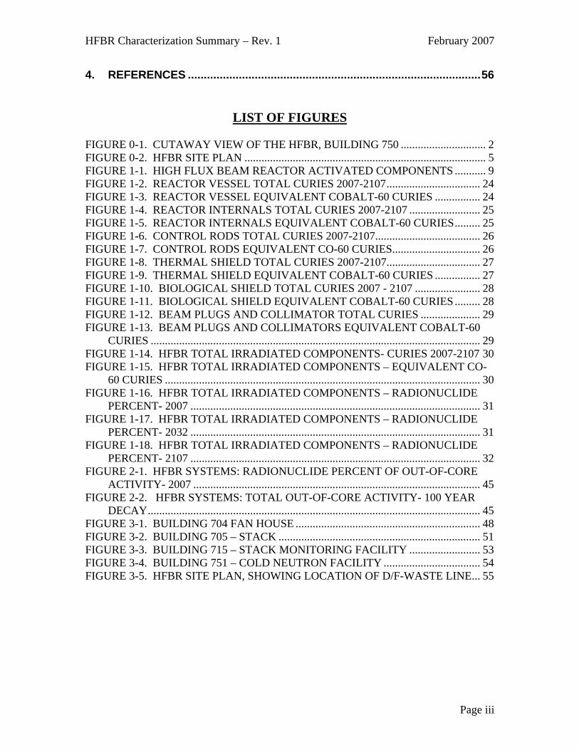
LIST OF FIGURES ..............................................................................................III
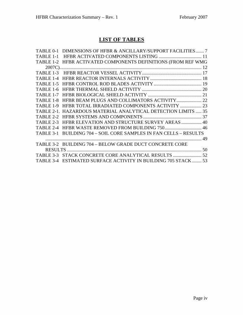
LIST OF TABLES............................................................................................... IV
0. HFBR CHARACTERIZATION SUMMARY ...................................................1
0.1 Objective:............................................................................................................... 1
0.2 Background Information: .................................................................................... 1
0.3 HFBR Confinement Building (Building 750) ..................................................... 2
0.4 HFBR Support Facilities ...................................................................................... 4
0.5 Previous HFBR Characterizations:..................................................................... 6
1. PART 1. CHARACTERIZATION SUMMARY - ACTIVATED COMPONENTS ....................................................................................................9
1.1 Summary of Activated Components ................................................................... 9
1.2 Current and Future Radioactivity Inventory for Activated Components .... 16
2. PART 2. CHARACTERIZATION SUMMARY – REACTOR BUILDING SYSTEMS, STRUCTURES, AND COMPONENTS............................................33
2.1 Summary Description of Reactor Building Systems, Structures, and Components ..................................................................................................................... 33
2.2 Characterization of Reactor Building Systems, Structures, & Components 34
2.3 Hazardous materials and safety concerns ........................................................ 35
3. PART 3. HFBR CHARACTERIZATION SUMMARY - ANCILLARY/SUPPORT FACILITIES AND SOIL CHARACTERIZATION ........47
3.1 Summary of Ancillary/Support Facilities......................................................... 47
3.2 Previous Characterizations for Ancillary/Support Facilities and Soil........... 47
3.3 Characterization Results for Ancillary/Support Facilities and Soil............... 48
Page ii
HFBR Characterization Summary – Rev. 1 February 2007
4. REFERENCES ............................................................................................56
LIST OF FIGURES
FIGURE 0-1. CUTAWAY VIEW OF THE HFBR, BUILDING 750 .............................. 2 FIGURE 0-2. HFBR SITE PLAN ..................................................................................... 5 FIGURE 1-1. HIGH FLUX BEAM REACTOR ACTIVATED COMPONENTS ........... 9 FIGURE 1-2. REACTOR VESSEL TOTAL CURIES 2007-2107................................. 24 FIGURE 1-3. REACTOR VESSEL EQUIVALENT COBALT-60 CURIES ................ 24 FIGURE 1-4. REACTOR INTERNALS TOTAL CURIES 2007-2107 ......................... 25 FIGURE 1-5. REACTOR INTERNALS EQUIVALENT COBALT-60 CURIES......... 25 FIGURE 1-6. CONTROL RODS TOTAL CURIES 2007-2107..................................... 26 FIGURE 1-7. CONTROL RODS EQUIVALENT CO-60 CURIES............................... 26 FIGURE 1-8. THERMAL SHIELD TOTAL CURIES 2007-2107................................. 27 FIGURE 1-9. THERMAL SHIELD EQUIVALENT COBALT-60 CURIES ................ 27 FIGURE 1-10. BIOLOGICAL SHIELD TOTAL CURIES 2007 - 2107 ....................... 28 FIGURE 1-11. BIOLOGICAL SHIELD EQUIVALENT COBALT-60 CURIES ......... 28 FIGURE 1-12. BEAM PLUGS AND COLLIMATOR TOTAL CURIES ..................... 29 FIGURE 1-13. BEAM PLUGS AND COLLIMATORS EQUIVALENT COBALT-60
CURIES .................................................................................................................... 29 FIGURE 1-14. HFBR TOTAL IRRADIATED COMPONENTS- CURIES 2007-2107 30 FIGURE 1-15. HFBR TOTAL IRRADIATED COMPONENTS – EQUIVALENT CO-
60 CURIES ............................................................................................................... 30 FIGURE 1-16. HFBR TOTAL IRRADIATED COMPONENTS – RADIONUCLIDE
PERCENT- 2007 ...................................................................................................... 31 FIGURE 1-17. HFBR TOTAL IRRADIATED COMPONENTS – RADIONUCLIDE
PERCENT- 2032 ...................................................................................................... 31 FIGURE 1-18. HFBR TOTAL IRRADIATED COMPONENTS – RADIONUCLIDE
PERCENT- 2107 ...................................................................................................... 32 FIGURE 2-1. HFBR SYSTEMS: RADIONUCLIDE PERCENT OF OUT-OF-CORE
ACTIVITY- 2007 ..................................................................................................... 45 FIGURE 2-2. HFBR SYSTEMS: TOTAL OUT-OF-CORE ACTIVITY- 100 YEAR
DECAY..................................................................................................................... 45 FIGURE 3-1. BUILDING 704 FAN HOUSE ................................................................. 48 FIGURE 3-2. BUILDING 705 – STACK ....................................................................... 51 FIGURE 3-3. BUILDING 715 – STACK MONITORING FACILITY ......................... 53 FIGURE 3-4. BUILDING 751 – COLD NEUTRON FACILITY .................................. 54 FIGURE 3-5. HFBR SITE PLAN, SHOWING LOCATION OF D/F-WASTE LINE... 55
Page iii
HFBR Characterization Summary – Rev. 1 February 2007
LIST OF TABLES
TABLE 0-1 DIMENSIONS OF HFBR & ANCILLARY/SUPPORT FACILITIES....... 7 TABLE 1-1 HFBR ACTIVATED COMPONENTS LISTING .................................... 11 TABLE 1-2 HFBR ACTIVATED COMPONENTS DEFINITIONS (FROM REF WMG
2007C)....................................................................................................................... 12 TABLE 1-3 HFBR REACTOR VESSEL ACTIVITY.................................................. 17 TABLE 1-4 HFBR REACTOR INTERNALS ACTIVITY ........................................... 18 TABLE 1-5 HFBR CONTROL ROD BLADES ACTIVITY ........................................ 19 TABLE 1-6 HFBR THERMAL SHIELD ACTIVITY .................................................. 20 TABLE 1-7 HFBR BIOLOGICAL SHIELD ACTIVITY ............................................. 21 TABLE 1-8 HFBR BEAM PLUGS AND COLLIMATORS ACTIVITY..................... 22 TABLE 1-9 HFBR TOTAL IRRADIATED COMPONENTS ACTIVITY .................. 23 TABLE 2-1. HAZARDOUS MATERIAL ANALYTICAL DETECTION LIMITS ..... 35 TABLE 2-2 HFBR SYSTEMS AND COMPONENTS ................................................. 37 TABLE 2-3 HFBR ELEVATION AND STRUCTURE SURVEY AREAS ................. 40 TABLE 2-4 HFBR WASTE REMOVED FROM BUILDING 750............................... 46 TABLE 3-1 BUILDING 704 – SOIL CORE SAMPLES IN FAN CELLS – RESULTS
................................................................................................................................... 49 TABLE 3-2 BUILDING 704 – BELOW GRADE DUCT CONCRETE CORE
RESULTS ................................................................................................................. 50 TABLE 3-3 STACK CONCRETE CORE ANALYTICAL RESULTS ........................ 52 TABLE 3-4 ESTIMATED SURFACE ACTIVITY IN BUILDING 705 STACK ........ 53
Page iv

HFBR Characterization Summary – Rev. 1 February 2007
0. HFBR Characterization Summary
0.1 Objective: The Brookhaven National Laboratory (BNL) High Flux Beam Reactor (HFBR) has been shut down since December 1996, and there have been several characterizations of the facility, including the reactor itself, systems and components, ancillary support structures, and the surrounding soil. These characterizations have involved direct radiation surveys, samples for radioactivity, and calculations of activated materials over a period of several years. The purpose of this HFBR Summary Report is to organize the results of the previous characterizations into a document that provides a “big picture” summary of relevant information in an understandable format. References are provided for access to the detailed data from the previous characterizations.
0.2 Background Information: The concept for the HFBR used a new approach in reactor design that was optimized to provide intense external beams of neutrons, primarily for neutron scattering experiments. The mission of the HFBR was to provide a source of neutrons for multidisciplinary scientific studies in chemistry, biology, and physics. Following a construction period of four years and one month, the HFBR achieved criticality on October 31, 1965. The reactor was originally designed for operation at a power level of 40 megawatts (MW). In addition to its external beams of neutrons, the HFBR provided seven sample irradiation thimbles for neutron activation experiments. An equipment upgrade in 1982 allowed operations at 60 MW, providing a peak thermal flux of 1.05E+15 neutrons/cm2-sec. (BNL 1996) In 1989, the reactor was shut down to reanalyze the safety impact of a hypothetical loss-of-coolant accident. The reactor was restarted in 1991 at 30 MW. The HFBR was shut down again in December 1996 for routine maintenance and refueling, when it was discovered that a leak in the spent fuel pool had released tritium-contaminated water to the ground. The reactor remained shut down for almost three years for safety and environmental reviews. By January 1998, all of the spent fuel was removed and shipped off-site. The shipment of the spent fuel and the disposal of miscellaneous reactor components from the canal were necessary to facilitate the canal draining and insertion of a double-walled stainless steel liner for restart. The Secretary of Energy, however, decided to permanently shut down the HFBR in November 1999. The majority of the HFBR facility is housed within the reactor confinement building (750). Support buildings and structures within the HFBR complex include the Stack (705), the Stack Monitoring Facility (715), and the Cold Neutron Facility (751). Several of these facilities also supported the Brookhaven Graphite Research Reactor (BGRR).
Page 1
HFBR Characterization Summary – Rev. 1 February 2007
0.3 HFBR Confinement Building (Building 750)
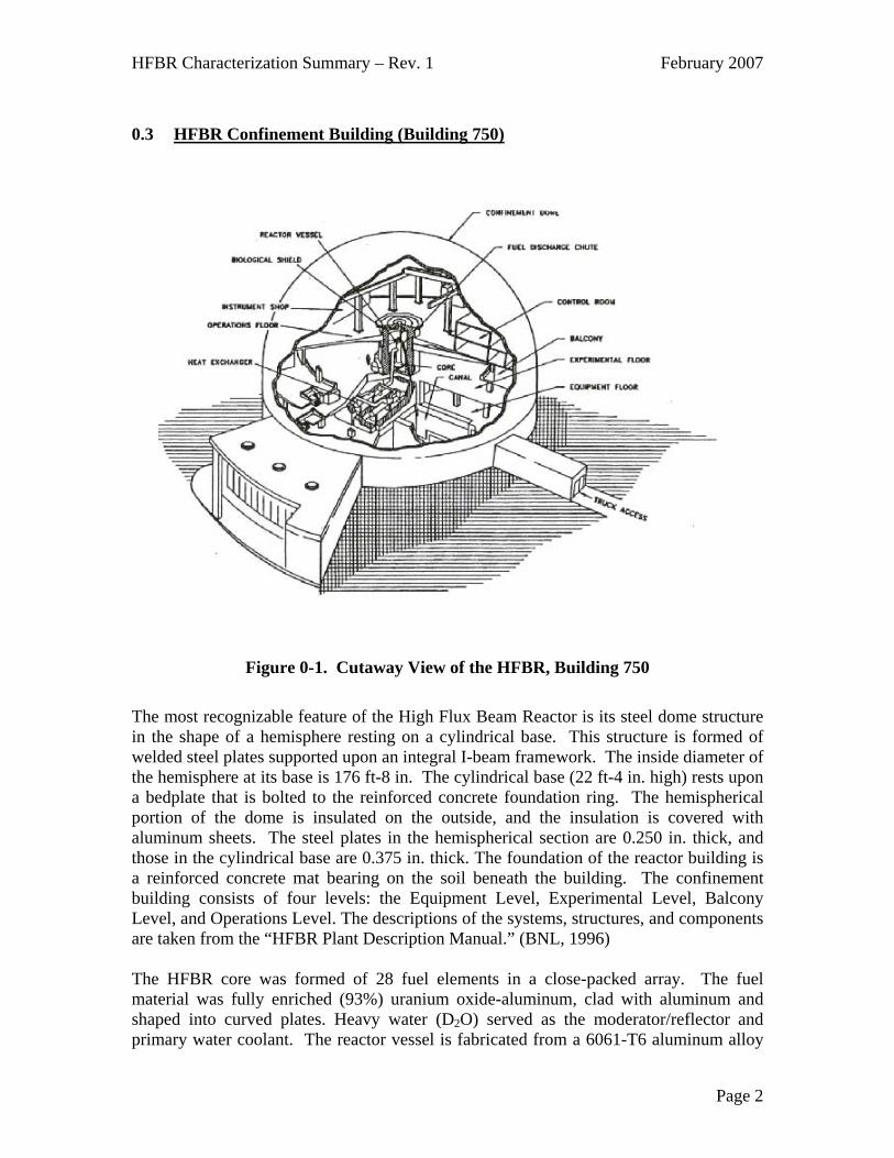
Figure 0-1. Cutaway View of the HFBR, Building 750
The most recognizable feature of the High Flux Beam Reactor is its steel dome structure in the shape of a hemisphere resting on a cylindrical base. This structure is formed of welded steel plates supported upon an integral I-beam framework. The inside diameter of the hemisphere at its base is 176 ft-8 in. The cylindrical base (22 ft-4 in. high) rests upon a bedplate that is bolted to the reinforced concrete foundation ring. The hemispherical portion of the dome is insulated on the outside, and the insulation is covered with aluminum sheets. The steel plates in the hemispherical section are 0.250 in. thick, and those in the cylindrical base are 0.375 in. thick. The foundation of the reactor building is a reinforced concrete mat bearing on the soil beneath the building. The confinement building consists of four levels: the Equipment Level, Experimental Level, Balcony Level, and Operations Level. The descriptions of the systems, structures, and components are taken from the “HFBR Plant Description Manual.” (BNL, 1996) The HFBR core was formed of 28 fuel elements in a close-packed array. The fuel material was fully enriched (93%) uranium oxide-aluminum, clad with aluminum and shaped into curved plates. Heavy water (D2O) served as the moderator/reflector and primary water coolant. The reactor vessel is fabricated from a 6061-T6 aluminum alloy
Page 2

HFBR Characterization Summary – Rev. 1 February 2007
and contained the active core, reflector and control rods and provided space and access for 16 experimental facilities, which utilized the high neutron flux in the core region. The vessel consists of an 82-in inside diameter spherical section welded via a transition piece to a 46-inch inside diameter cylinder. Including the closure flange, the over-all height of the vessel assembly is 24.75 ft. The nine horizontal beam reentry tubes are integral (welded) parts of the vessel’s spherical section. There are 16 control rod blades, separated into main and auxiliary rod groups, each containing 8 rods. The control rods operated in the reflector region, just outside the core. The control rod blades are angle-shaped in cross-section, and are made of europium oxide (Eu2O3) and dysprosium oxide (Dy2O3) in stainless steel, all clad in stainless steel. In 2000, the reactor vessel was drained of approximately 1,500 gallons of heavy water (D2O), and replaced with a similar volume of light water (H2O). The D2O was shipped off site. In 2003, the light water, in turn, was drained after completion of a CO2 cavity gas test. Currently, the vessel is filled with helium (He), an inert gas maintained at a slight positive pressure to preserve the vessel from corrosion until future decommissioning. The Equipment Level, located at an elevation of 93 ft-0 in. above sea level, contains most of the reactor support and building systems equipment, such as pumps, heat exchangers, filters, wastewater storage tanks, HVAC, and piping networks. Shielded cells for the primary cooling water system pumps and heat exchangers are located in the center of the floor. The spent fuel storage canal (also referred to as the spent fuel pool), located to the east of the shielded cells, is 8 ft wide, 43 ft long and 20 ft deep for most of its length. A 30-foot deep section, 8-ft-6 in long resides under the fuel discharge chute at the west end. A small bay, 8 ft wide, 10 ft long and 20 ft deep, located on the north side of the canal, was used primarily for cutting operations to remove the aluminum transition pieces from the spent fuel elements. The heavy water purification system and one of two storage tanks are installed in pits sunken into the floor in the northeast quadrant of the Equipment Level. Three rooms along the south wall are partitioned from the rest of the level by a containment wall. These are the transformer room, the blower room, and the generator room. Each of these rooms has access from outside the building. The Experimental Level, located at an elevation of 113 ft-6 in., was dedicated to the scientific users. The reactor biological shield occupies the central portion of this level, with open floor space surrounding it for the external beam experiments. Laboratories and offices are located along the perimeter wall of the level. A 20-ton capacity radial traveling beam crane services this level. The Balcony Level, located at an elevation of 128 ft-6 in., is approximately 21 ft. wide, with its outer circumference at the confinement shell. Offices, locker rooms, toilets, and HVAC equipment are contained on this level. The Operations Level is the top floor of the building located at an elevation of 141 ft-6 in. The reactor shielding structure rises 7.5 ft. above the floor at the center of the building.
Page 3

HFBR Characterization
Summary – Rev. 1 February 2007
Page 4
The southwest quadrant of the level contains an enclosed process area (the Greenhouse), which houses pumps, a heat exchanger and piping associated with the experimental facilities cooling water system. The second of the two heavy water storage tanks is located in this area. A series of offices and workrooms are located on the east side of the Level, with the reactor control room occupying the second story above these offices. A two-story cinderblock structure containing the instrument shop and offices is located on the west side of this Level. Two air intake ports are located on the Balcony Level. Access into the confinement building is provided by four airlocks: a personnel-size airlock (3 feet - 3 inches by 7 feet by 9 feet) located between the Equipment and Experimental Levels on the south side of the building, a forklift size (6 feet x 8 feet – 9 inches by 18 feet) located on the north side of the Experimental Level and two tractor trailer size (12 feet x 14 feet x 65 feet), one entering on the north side of the Experimental Level and the other on the east side of the Equipment Level. 0.4 HFBR Support Facilities Figure 0-2 is a site plan showing the location of the HFBR ancillary/support facilities, and Table 0-1 shows the dimensions of these facilities. The Fan House (Building 704) is a one-story, above-grade structure approximately 168 feet long by 60 feet wide. Concrete block and brick walls and a flat built-up roof cover structural steel supports. This building has been associated with the operation of both the BGRR and HFBR. Most of the equipment associated with the BGRR, such as the exhaust fans, motors and above-grade air ducting, has been removed as part of the BGRR decommissioning project. The fan discharge ducts below the building, which exhausted BGRR air into the base of the stack, remain. The south side of the fan house contains the electrical switchgear currently associated with the HFBR facility. The Stack (Building 705) was also associated with operation of both the BGRR and HFBR and is included among the HFBR complex buildings. The stack was designed to convey fan discharge radioactive air sufficiently high above the ground (320 feet) to permit adequate mixing and dilution with atmospheric air. (BNL, 1964) Exhaust air, discharged from HFBR building 750 exhaust fans, passes through underground ductwork (750 Plenum Exhaust Line) to a bank of particulate and charcoal filters, before entering the base of the stack. The exhaust air from the BGRR was pulled by fans through an Underground Plenum and into the stack for discharge to the atmosphere. The Stack Monitoring Facility (Building 715) housed instrumentation used to monitor stack effluents. The Cold Neutron Facility (CNF -Building 751) has been surveyed and is now released from radiological controls; it is no longer considered part of the HFBR facility.

HFBR Characterization
Summary – Rev. 1 February 2007
Page 5
Figure 0-2. HFBR Site Plan

HFBR Characterization Summary – Rev. 1 February 2007
0.5 Previous HFBR Characterizations: The previous HFBR characterization efforts can be divided into the following groupings: 1. Activated Components (see HFBR Summary Report, Part 1)
The activated components of the HFBR considered in this part include the reactor vessel, reactor vessel internals, control rod blades, thermal shield, biological shield, and beam plugs, including collimators. The beam plugs and collimators are located in the beam plug storage facility (cheese box) and in transfer shields on the Experimental Level.
2. Reactor Building Structures, Systems, and Components (see HFBR Summary Report,
Part 2)
Characterization of Building 750 consisted of the facility structure itself, including floors, walls, and the dome and it included systems and components within the building. The building was divided into 115 survey areas, and 46 systems. Non-radiological hazards for the building systems, structures, and components are addressed in this section
3. Ancillary/Support Structures and Soil Characterization (see HFBR Summary Report, Part 3)
Characterization of ancillary structures and buildings that supported the HFBR is addressed in this part, and the characterization includes radiological and non-radiological hazards. The soils surrounding the HFBR and support buildings were evaluated for possible radioactive and non-radioactive hazardous material contamination.
Page 6

HFBR Characterization Summary – Rev. 1 February 2007
Table 0-1 Dimensions of HFBR & Ancillary/Support Facilities
704 Fan House Main Section (Electrical switch gear, battery room, Fan Rooms) – Overall dimensions: 130’-0” long x 59’-3” wide x 20’-0” tall structure 6”-12” thick concrete slab floor, 7,702.5 square feet area 2’-1” thick brick walls (1’-1” brick, 4” air gap, 8” brick) 4” thick concrete slab roof Repair Shop/Secondary Fan Room – Overall dimensions: 54’-3” long x 27’-5” wide x 13’-0” tall structure 6” thick concrete slab floor, 1,487.35 square feet area 2’-1” thick brick walls (1’-1” brick, 4” air gap, 8” brick) 4” thick concrete slab roof Emergency Fan Room – Overall dimensions: 26’-2” long x 9’-6” wide x 13’-0” tall structure 6” thick concrete slab floor, 248.6 square feet area 2’-1” thick brick walls (1’-1” brick, 4” air gap, 8” brick) 4” thick concrete slab roof Exit Air Filter Facility 1’-6” thick concrete slab floor, 682.6 square feet area 1’-0” thick concrete walls, 125’-10” perimeter length x 11’-1” tall 1’-10” thick concrete slab roof, 682.6 square feet area 705 Underground Plenum (Duct) Below grade section – Overall dimensions: 52’-0” long x 12’-0” wide x 13’-0 tall 1’-0” thick concrete walls, roof, and floor Above grade section - Overall dimensions: 56’-0” long x 12’-0” wide x 17’-0 tall 1’-0” thick concrete walls, roof, and floor 715 Stack Monitoring Facility Overall dimensions: 20’-0” long x 10’-0” wide x 10’-0” tall structure 7” thick concrete slab floor, 200 square feet area 8” thick wood walls (studs and siding) 10” thick wood roof (joists, sheets, shingles)
Page 7

HFBR Characterization Summary – Rev. 1 February 2007
750 HFBR Confinement Dome – Overall dimensions: 180 foot diameter half sphere Dome walls consist of 49,769 square feet of ¼” thick steel plating covered
uniformly by 4” thick fibrous insulation and a 1/8” thick aluminum exterior skin Foundation – Equipment Level Floor Slab – Perimeter slab: 3’-0” thick heavily reinforced concrete slab, 2,824 square feet area Interior slab: 5’-0” thick heavily reinforced concrete slab, 16,413 square feet area 750 Plenum (30” Exhaust Line) 390’ long x 30” diameter concrete pipe, 3/16” thick D/F-Waste Line 1,117’ double-walled (2” x 4”) carbon steel pipe between Buildings 750 and 801. 705 Stack Overall height: 320’-0” Interior top diameter: 18.42’ Interior base diameter: 26.58’ Thickness @ top: ~ 7” Thickness @ bottom: ~ 14” 705 Stack Pedestal Shape: Octagon Overall height: 21.5’ Width: 30.5’ Interior diameter: 26.0’
Page 8

HFBR Characterization Summary – Rev. 1 February 2007
1. Part 1. Characterization Summary - Activated Components 1.1 Summary of Activated Components The activated components of the HFBR considered here include the reactor vessel, reactor vessel internals, control rod blades, thermal shield and the biological shield (bioshield). The beam plugs are discussed only for information, as the current plans call for the beam plugs to be removed from the HFBR and are stored in a shielded area outside of the bioshield area on the experimental level of the HFBR. The activities of the activated components were determined based on WMG, Inc. calculations (WMG 2007a, WMG 2000b and WMG 2007c), and the beam plugs and collimators activities were determined based on an earlier calculation (Tichler 1995). Figure 1-1 shows the general configuration of the reactor vessel, the thermal shield, and the reactor internals, including the control rod blades.
Figure 1-1. High Flux Beam Reactor Activated Components
Page 9
HFBR Characterization Summary – Rev. 1 February 2007
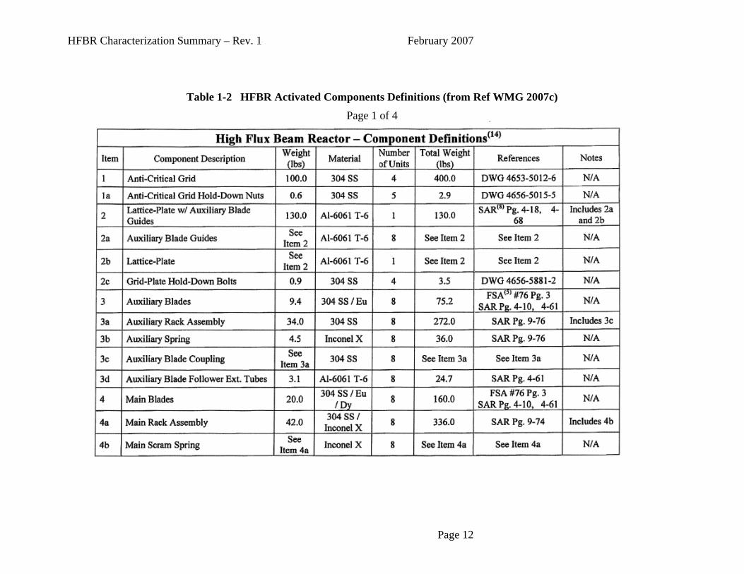
WMG, Inc. performed a recalculation of the activity of irradiated components in late 2006 and early 2007. The calculation of the activity in the beam plugs was not affected by this recalculation. The summary of the results are shown in WMG Calculation 6117-CRE-072, “Final Characterization of the Brookhaven National Laboratory HFBR” (WMG 2007c), and these calculations were reviewed by Brookhaven scientists (Cheng 2007). The specific list of activated components was taken from the WMG calculation (WMG 2007c); these components are shown in Table 1-1, and a more detailed breakdown is shown in Table 1-2.
Page 10

HFBR Characterization
Summary – Rev. 1 February 2007
Page 11
Index No.
HFBR Component Material
Weight (lb) Comments
A-1 Reactor VesselAluminum-
6061 10,000 lb
The reactor vessel is a massive aluminum component that stands just over 21 feet high. It consists of a lower hollow sphere approximately 7 feet in diameter, constructed of 1-3/4" thick aluminum and includes the experiment beam port thimbles. The upper portion of the vessel is a cylinder approximately 4 feet in diameter that is welded, via a transition plate, to the bottom sphere.
A-2
Reactor Internals, Edge/In-Core
Irradiation Thimbles Aluminum-
6061 166 lb
The control rod blades consist of main blades and auxiliary
e ect e
r. ss in
th
ed
A-3 Control Rod Blades
Europium and Dysprosium absorbers 1571 lb
blades. For purposes of the summing of components, the support tube, main rack assembly, and auxiliary rack assembly are included with the control rod blades.
A-4 Thermal ShieldCarbon steel
and lead 136,000 lb
The thermal shield is located in the base of the heavy concretpit. The primary function of the thermal shield was to protthe surrounding concrete biological shield from the extremheat of the reactor vessel.
A-5Reactor Internals,
Flow ShroudAluminum-
6061 962 lb
A-6Grid Plate and
SaddleAluminum-
6061 229 lb
A-7Reactor Internals, Transition plate
304 Stainless Steel 263 lb
The reactor transition plate is a horizontal fixture located immediately above the reactor core that isolates the reactor sphere from the reactor vessel upper cylinder. The plate provided mechanical isolation and alignment of the vertical control rod mechanisms.
A-8
Reactor Internals, Grid Plate Hold-downs and Anti-
Critical Grid304 Stainless
Steel 413 lb
The anti-critical grid consists of four quarter sections, each containing 28, 1-in. diameter 304 Stainless Steel bars configured below the grid plate at the bottom of the reactoThe anti-critical grid was designed to prevent a critical mathe event of a core meltdown.
N/A Biological ShieldHeavy
Concrete 3,420,000 lb
The biological shield is constructed of heavy concrete, wiiron punchings (~60% by weight) added to increase the density. Weight is for the entire shield, although the activatportion is on the inner diameter and is closer to 26,000 lb.Note that the biological shield is an integral part of the structure and support of Building 750.
Table 1-1 HFBR Activated Components Listing
HFBR Characterization Summary – Rev. 1 February 2007
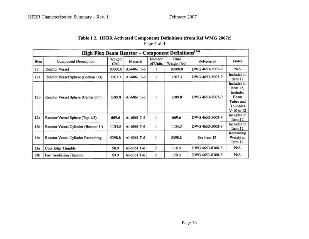
Table 1-2 HFBR Activated Components Definitions (from Ref WMG 2007c) Page 1 of 4
Page 12

HFBR Characterization Summary – Rev. 1 February 2007
Table 1 2. HFBR Activated Components Definitions (from Ref WMG 2007c) Page 2 of 4
Page 13
HFBR Characterization Summary – Rev. 1 February 2007
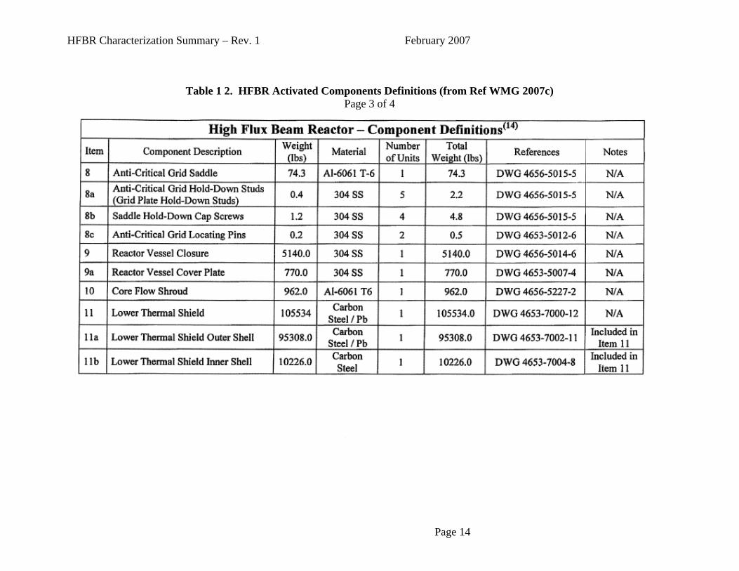
Table 1 2. HFBR Activated Components Definitions (from Ref WMG 2007c) Page 3 of 4
Page 14
HFBR Characterization
Summary – Rev. 1 February 2007
Page 15
Table 1 2. HFBR Activated Components Definitions (from Ref WMG 2007c) Page 4 of 4

HFBR Characterization
Summary – Rev. 1 February 2007
Page 16
1.2 Current and Future Radioactivity Inventory for Activated Components The activated components contain the vast majority (>99% in 2007) of the total radioactivity remaining at the HFBR. The physical form of these activated components (activated metal) makes the hazard primarily a direct exposure risk and not a contamination risk. The reactor vessel, internals, and the activated portion of the biological shield are well shielded in the HFBR’s current condition, and there are no significant radiological hazards from those materials until they are disturbed during decommissioning. The beam plugs and collimators have been removed from the biological shield area and are in storage in a shielded condition. The following tables and figures are presented to show the radioactivity contents for the reactor vessel and other components, and they present the results of radioactive decay over the next 100 years. Half-lives of radionuclides were taken from “Nuclides and Isotopes, Chart of the Nuclides (KAPL 2002). The term “Co-60 Equivalent” represents the number of curies of Co-60 that would provide approximately the same gamma radiation hazard as the total curies of the mix of radionuclides.

HFBR Characterization Summary – Rev. 1 February 2007
Table 1-3 HFBR Reactor Vessel Activity
Jan-2007 Jan-2012 Jan-2017 Jan-2027 Jan-2037 Jan-2047 Jan-2057 Jan-2082 Jan-2107
NuclideHalf-Life
(yr) Ci Ci Ci Ci Ci Ci Ci Ci Ci
Fe-55 2.7 147 41 12 1 0 0 0 0 0
Co-60 5.27 33 17 9 2 1 0 0 0 0
Ni-59 76,000 1 1 1 1 1 1 1 1 1
Ni-63 100 199 192 186 173 161 151 141 118 99
Total Ci N/A 380 251 207 177 163 151 141 119 100
Years Decay 0 5 10 20 30 40 50 75 100Equivalent Co-60
Curies 33 17 9 2 1 0 0 0 0
Page 17
HFBR Characterization Summary – Rev. 1 February 2007
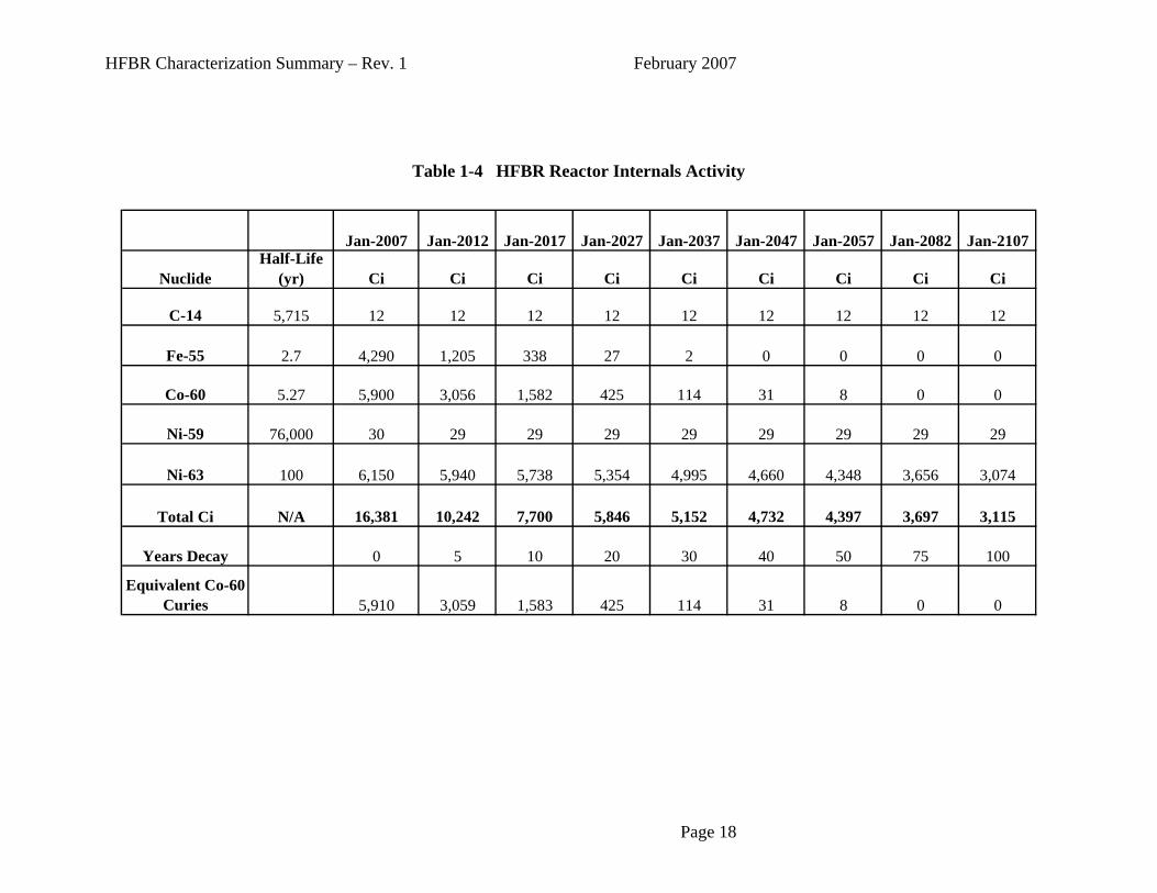
Table 1-4 HFBR Reactor Internals Activity
Jan-2007 Jan-2012 Jan-2017 Jan-2027 Jan-2037 Jan-2047 Jan-2057 Jan-2082 Jan-2107
NuclideHalf-Life
(yr) Ci Ci Ci Ci Ci Ci Ci Ci Ci
C-14 5,715 12 12 12 12 12 12 12 12 12
Fe-55 2.7 4,290 1,205 338 27 2 0 0 0 0
Co-60 5.27 5,900 3,056 1,582 425 114 31 8 0 0
Ni-59 76,000 30 29 29 29 29 29 29 29 29
Ni-63 100 6,150 5,940 5,738 5,354 4,995 4,660 4,348 3,656 3,074
Total Ci N/A 16,381 10,242 7,700 5,846 5,152 4,732 4,397 3,697 3,115
Years Decay 0 5 10 20 30 40 50 75 100
Equivalent Co-60 Curies 5,910 3,059 1,583 425 114 31 8 0 0
Page 18

HFBR Characterization Summary – Rev. 1 February 2007
Table 1-5 HFBR Control Rod Blades Activity
Jan-2007 Jan-2012 Jan-2017 Jan-2027 Jan-2037 Jan-2047 Jan-2057 Jan-2082 Jan-2107
NuclideHalf-Life
(yr) Ci Ci Ci Ci Ci Ci Ci Ci Ci
C-14 5.72E+03 7 7 7 7 7 7 7 7 7
Fe-55 2.73E+00 6,170 1,733 486 38 3 0 0 0 0
Co-60 5.27E+00 7,060 3,657 1,893 508 136 37 10 0 0
Ni-59 7.60E+04 17 17 17 17 17 17 17 17 17
Ni-63 1.00E+02 3,700 3,574 3,452 3,221 3,005 2,804 2,616 2,199 1,849
Eu-154 8.59E+00 3,610 2,411 1,610 718 320 143 64 8 1
Eu-155 4.75E+00 1,340 646 311 72 17 4 1 0 0
Total Ci N/A 21,904 12,044 7,777 4,582 3,505 3,011 2,714 2,232 1,874
Years Decay 0 5 10 20 30 40 50 75 100
Equivalent Co-60 Curies 9,131 3,661 1,895 508 136 37 10 0 0
Page 19

HFBR Characterization Summary – Rev. 1 February 2007
Table 1-6 HFBR Thermal Shield Activity
Jan-2007 Jan-2012 Jan-2017 Jan-2027 Jan-2037 Jan-2047 Jan-2057 Jan-2082 Jan-2107
NuclideHalf-Life
(yr) Ci Ci Ci Ci Ci Ci Ci Ci Ci
C-14 5,715 7 7 7 7 7 7 7 7 7
Fe-55 2.7 20,100 5,645 1,584 125 10 1 0 0 0
Co-60 5.27 2,910 1,507 780 209 56 15 4 0 0
Ni-59 76,000 14 14 14 14 14 14 14 14 14
Ni-63 100 1,870 1,806 1,745 1,628 1,519 1,417 1,322 1,112 935
Total Ci N/A 24,902 8,980 4,131 1,984 1,606 1,454 1,348 1,133 956
Years Decay 0 5 10 20 30 40 50 75 100
Equivalent Co-60 Curies 2,957 1,520 784 210 56 15 4 0 0
Page 20

HFBR Characterization Summary – Rev. 1 February 2007
Table 1-7 HFBR Biological Shield Activity
Jan-2007 Jan-2012 Jan-2017 Jan-2027 Jan-2037 Jan-2047 Jan-2057 Jan-2082 Jan-2107
NuclideHalf-Life
(yr) Ci Ci Ci Ci Ci Ci Ci Ci Ci
H-3 12.3 7 5 4 2 1 1 0 0 0
Fe-55 2.7 98 27 8 1 0 0 0 0 0
Co-60 5.27 12 6 3 1 0 0 0 0 0
Ni-63 100 8 8 7 7 7 6 6 5 4
Total Ci N/A 125 47 23 11 8 7 6 5 4
Years Decay 0 5 10 20 30 40 50 75 100
Equivalent Co-60 Curies 12 6 3 1 0 0 0 0 0
Page 21
HFBR Characterization Summary – Rev. 1 February 2007
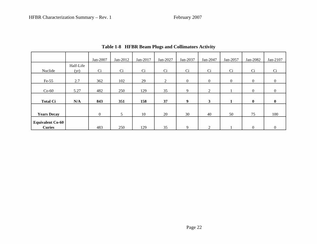
Table 1-8 HFBR Beam Plugs and Collimators Activity
Jan-2007 Jan-2012 Jan-2017 Jan-2027 Jan-2037 Jan-2047 Jan-2057 Jan-2082 Jan-2107
NuclideHalf-Life
(yr) Ci Ci Ci Ci Ci Ci Ci Ci Ci
Fe-55 2.7 362 102 29 2 0 0 0 0 0
Co-60 5.27 482 250 129 35 9 2 1 0 0
Total Ci N/A 843 351 158 37 9 3 1 0 0
Years Decay 0 5 10 20 30 40 50 75 100
Equivalent Co-60 Curies 483 250 129 35 9 2 1 0 0
Page 22

HFBR Characterization
Summary – Rev. 1 February 2007
Page 23
2007 2012 2017 2027 2037 2047 2057 2082 2107
NuclideHalf-Life
(yr) Ci Ci Ci Ci Ci Ci Ci Ci Ci
H-3 12.3 7 5 4 2 1 1 0 0 0
C-14 5,715 26 26 26 26 26 26 26 26 25
Fe-55 2.7 31,150 8,749 2,455 194 15 1 0 0 0
Co-60 5.3 16,389 8,489 4,395 1,179 316 85 23 1 0
Ni-59 76,000 62 62 62 62 62 62 62 62 62
Ni-63 100 11,932 11,525 11,132 10,387 9,691 9,042 8,436 7,093 5,964
Eu-154 8.6 3,610 2,411 1,610 718 320 143 64 8 1
Eu-155 4.8 1,336 644 310 72 17 4 1 0 0
Total Ci N/A 64,511 31,911 19,995 12,639 10,448 9,362 8,611 7,190 6,052
Years Decay 0 5 10 20 30 40 50 75 100Equivalent Co-
60 Curies 18,518 9,870 5,304 1,579 494 164 58 6 1
Table 1-9 HFBR Total Irradiated Components Activity

HFBR Characterization Summary – Rev. 1 March 2007
0
50
100
150
200
250
300
350
400
2007
2017
2027
2037
2047
2057
2067
2077
2087
2097
2107
Year
Cur
ies
Ci for Reactor Vessel is 0.6% of Total Irradiated Components
Figure 1-2. Reactor Vessel Total Curies 2007-2107
0
5
10
15
20
25
30
35
40
2007
2017
2027
2037
2047
2057
2067
2077
2087
2097
2107
Year
Equi
vale
nt C
o-60
Cur
ies
Equivalent Co-60 Ci for Reactor Vessel is 0.2% of Total Irradiated Components
Figure 1-3. Reactor Vessel Equivalent Cobalt-60 Curies
Page 24
HFBR Characterization Summary – Rev. 1 February 2007
0
2,000
4,000
6,000
8,000
10,000
12,000
14,000
16,000
18,000
2007
2017
2027
2037
2047
2057
2067
2077
2087
2097
2107
Year
Cur
ies
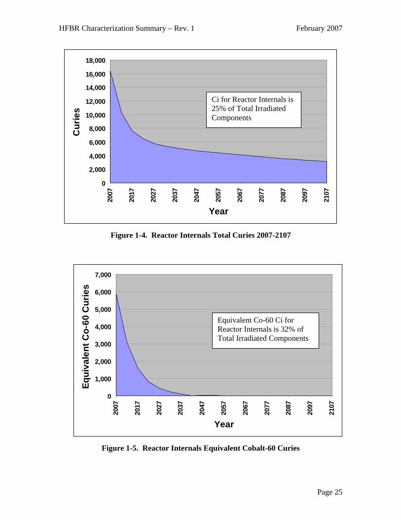
Ci for Reactor Internals is 25% of Total Irradiated Components
Figure 1-4. Reactor Internals Total Curies 2007-2107
0
1,000
2,000
3,000
4,000
5,000
6,000
7,000
2007
2017
2027
2037
2047
2057
2067
2077
2087
2097
2107
Year
Equi
vale
nt C
o-60
Cur
ies
Equivalent Co-60 Ci for Reactor Internals is 32% of Total Irradiated Components
Figure 1-5. Reactor Internals Equivalent Cobalt-60 Curies
Page 25
HFBR Characterization Summary – Rev. 1 February 2007
0
5,000
10,000
15,000
20,000
25,000
2007
2017
2027
2037
2047
2057
2067
2077
2087
2097
2107
Year
Cur
ies
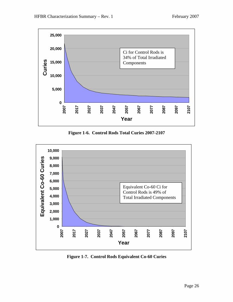
Ci for Control Rods is 34% of Total Irradiated Components
Figure 1-6. Control Rods Total Curies 2007-2107
0
1,000
2,000
3,000
4,000
5,000
6,000
7,000
8,000
9,000
10,000
2007
2017
2027
2037
2047
2057
2067
2077
2087
2097
2107
Year
Equi
vale
nt C
o-60
Cur
ies
Equivalent Co-60 Ci for Control Rods is 49% of Total Irradiated Components
Figure 1-7. Control Rods Equivalent Co-60 Curies
Page 26

HFBR Characterization Summary – Rev. 1 February 2007
0
5,000
10,000
15,000
20,000
25,000
30,000
2007
2017
2027
2037
2047
2057
2067
2077
2087
2097
2107
Year
Cur
ies
Ci for Thermal Shield is 39% of Total Irradiated Components
Figure 1-8. Thermal Shield Total Curies 2007-2107
0
500
1,000
1,500
2,000
2,500
3,000
3,500
2007
2017
2027
2037
2047
2057
2067
2077
2087
2097
2107
Year
Equi
vale
nt C
o-60
Cur
ies
Equivalent Co-60 Ci for Thermal Shield is 16% of Total Irradiated Components
Figure 1-9. Thermal Shield Equivalent Cobalt-60 Curies
Page 27

HFBR Characterization Summary – Rev. 1 February 2007
0
20
40
60
80
100
120
140
2007
2017
2027
2037
2047
2057
2067
2077
2087
2097
2107
Year
Cur
ies
Ci for Biological Shield is 0.2% of Total Irradiated Components
Figure 1-10. Biological Shield Total Curies 2007 - 2107
0
2
4
6
8
10
12
14
2007
2017
2027
2037
2047
2057
2067
2077
2087
2097
2107
Year
Equi
vale
nt C
o-60
Cur
ies
Equivalent Co-60 Ci for Biological Shield is 0.1% of Total Irradiated Components
Figure 1-11. Biological Shield Equivalent Cobalt-60 Curies
Page 28

HFBR Characterization Summary – Rev. 1 February 2007
0
100
200
300
400
500
600
700
800
900
2007
2017
2027
2037
2047
2057
2067
2077
2087
2097
2107
Year
Cur
ies
Figure 1-12. Beam Plugs and Collimator Total Curies
0
100
200
300
400
500
600
2007
2017
2027
2037
2047
2057
2067
2077
2087
2097
2107
Year
Equi
vale
nt C
o-60
Cur
ies
Figure 1-13. Beam Plugs and Collimators Equivalent Cobalt-60 Curies
Page 29

HFBR Characterization Summary – Rev. 1 February 2007
0
10,000
20,000
30,000
40,000
50,000
60,000
70,000
2007
2017
2027
2037
2047
2057
2067
2077
2087
2097
2107
Year
Cur
ies
Figure 1-14. HFBR Total Irradiated Components- Curies 2007-2107
0
2,000
4,000
6,000
8,000
10,000
12,000
14,000
16,000
18,000
20,000
2007
2017
2027
2037
2047
2057
2067
2077
2087
2097
2107
Year
Equi
vale
nt C
o-60
Cur
ies
Figure 1-15. HFBR Total Irradiated Components – Equivalent Co-60 Curies
Page 30
HFBR Characterization Summary – Rev. 1 February 2007
Eu-1552%Eu-154
6%
Ni-6319%
Co-6025%
Fe-5548%
Total Ci = 65,000 Ci
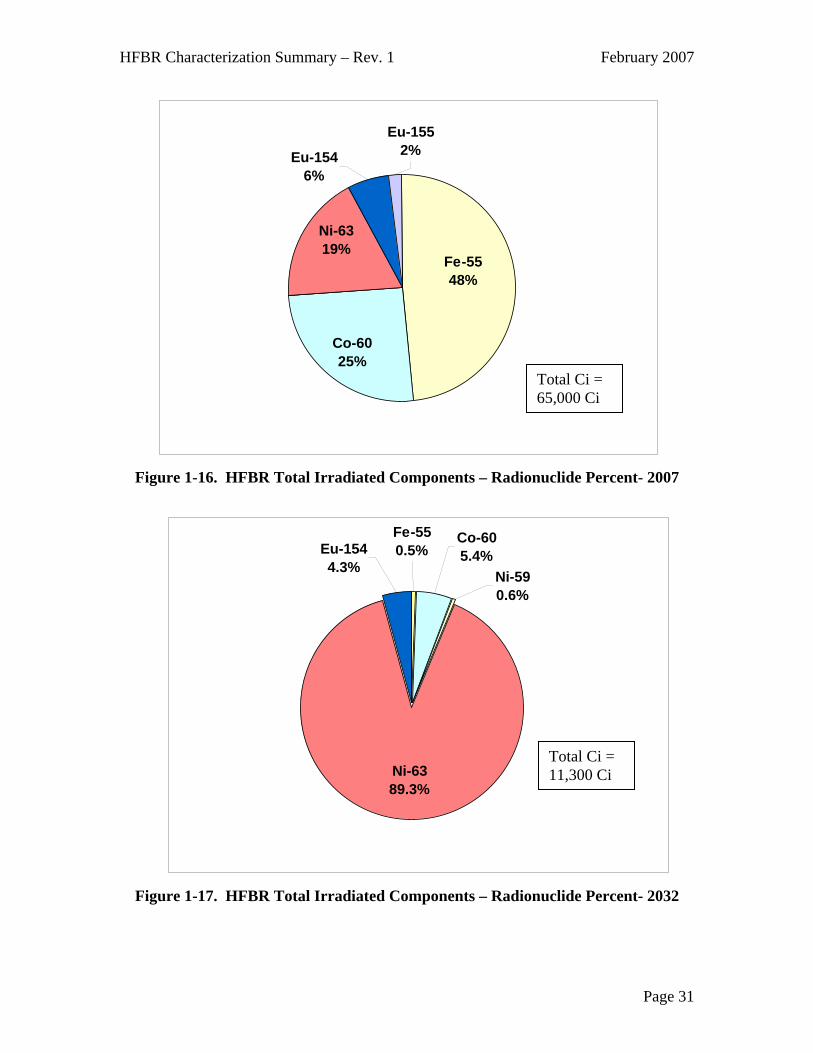
Figure 1-16. HFBR Total Irradiated Components – Radionuclide Percent- 2007
Fe-550.5%
Co-605.4%Eu-154
4.3%
Ni-6389.3%
Ni-590.6%
Total Ci = 11,300 Ci
Figure 1-17. HFBR Total Irradiated Components – Radionuclide Percent- 2032
Page 31
HFBR Characterization Summary – Rev. 1 February 2007
C-140.4%
Ni-6398.5%
Ni-591.0%
Total Ci = 6,050 Ci
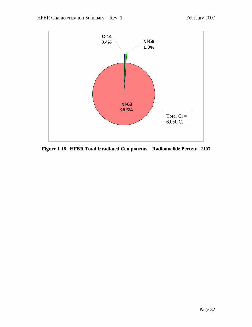
Figure 1-18. HFBR Total Irradiated Components – Radionuclide Percent- 2107
Page 32

HFBR Characterization Summary – Rev. 1 March 2007
2. Part 2. Characterization Summary – Reactor Building Systems, Structures, and Components
2.1 Summary Description of Reactor Building Systems, Structures, and
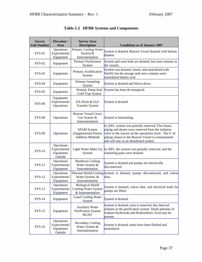
Components Characterization of Building 750 consisted of the facility structure itself, including floors, walls, and the dome, and it included systems and components within the building. A more detailed description of the facility is contained in the HFBR Plant Description Manual (BNL, 1996) and in the introductory portion of this document, a synopsis of the reactor building and structures is provided below. The steel dome structure acts as the confinement of the HFBR, and it is in the shape of a hemisphere resting on a cylindrical base. The hemispherical portion of the dome is insulated on the outside, and the insulation is covered with aluminum sheets. The confinement building consists of four levels: the Equipment Level, Experimental Level, Balcony Level, and Operations Level. The Equipment Level contains most of the reactor support and building systems equipment, such as pumps, heat exchangers, filters, wastewater storage tanks, Heating Ventilation and Air Conditioning (HVAC), and piping networks. Shielded cells for the primary cooling water system pumps and heat exchangers are located in the center of the floor. The spent fuel storage canal resides under the fuel discharge chute at the west end. The heavy water purification system and one of two storage tanks are installed in pits sunken into the floor of the Equipment Level. The Experimental Level was dedicated to the scientific users. The reactor biological shield occupies the central portion of this level, with open floor space surrounding it for the external beam experiments. Laboratories and offices are located along the perimeter wall of the level. The Balcony Level is approximately 21 feet wide, with its outer circumference at the confinement shell. Offices, locker rooms, toilets, and HVAC equipment are contained on this level. The Operations Level is the top floor of the building. The reactor shielding structure rises above the floor at the center of the building. The level contains an enclosed process area (the Greenhouse), which houses pumps, a heat exchanger and piping associated with the experimental facilities cooling water system. A series of offices and workrooms are located on the east side of the Level, with the reactor control room occupying the second story above these offices The list of systems considered in this section is shown in Table 2-2, “HFBR Systems and Components.”
Page 33

HFBR Characterization Summary – Rev. 1 February 2007
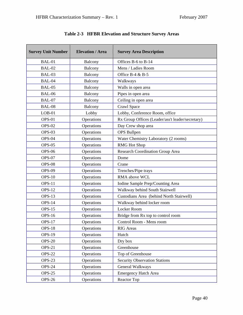
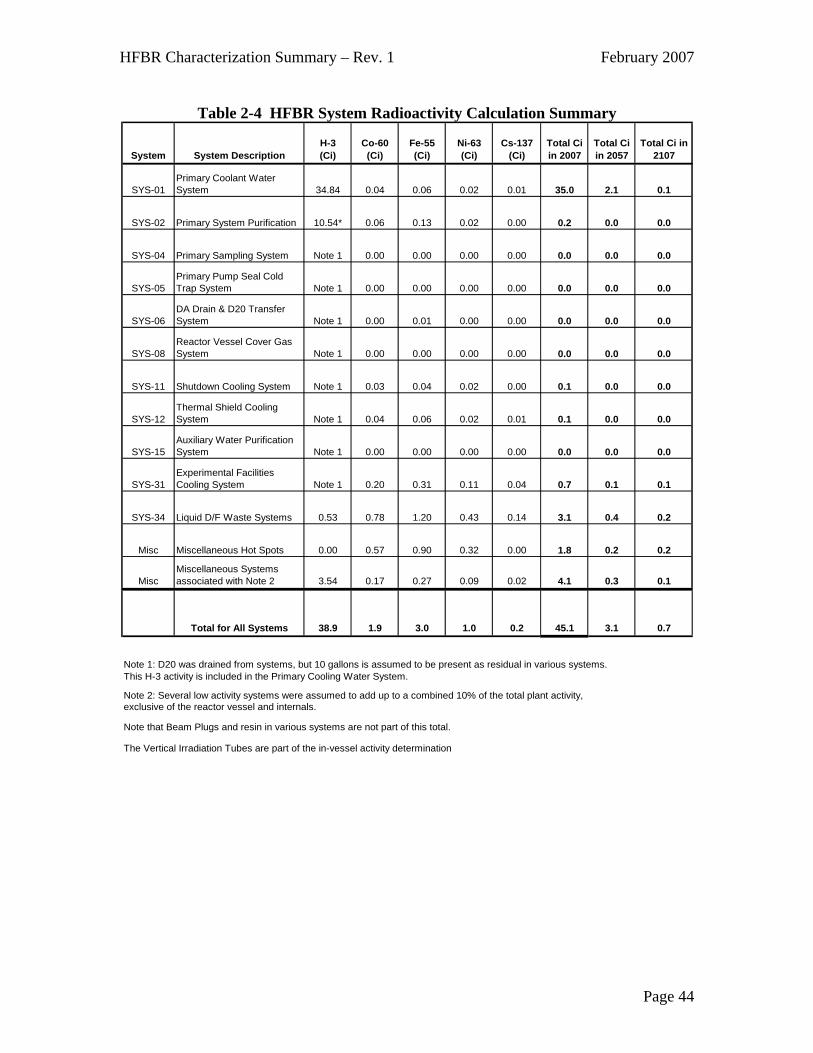
2.2 Characterization of Reactor Building Systems, Structures, & Components A number of characterization efforts have been undertaken in order to better understand the remaining hazards inside the HFBR (Building 750). These characterizations were intended to support a variety of purposes, including current work activities, long-term storage and maintenance, and decommissioning. A portion of the HFBR characterization was conducted in 2001, when deactivation of the facility was ongoing. At that time, many of the plant systems were operational and the experimental level still had significant amounts of equipment in place, and some personnel were stationed in the HFBR as their routine place of work. A “Characterization Project Plan” was developed (BNL, 2001a) in March 2001, and since additional cleanup was being performed, the surveys were planned as a “snapshot” of the conditions at that time. The results of that characterization were reported in September 2001 in the “HFBR Final Characterization Report” (Cabrera 2001b). It was understood that future operational and remediation activities could change the characterization results. The survey area breakdowns utilized for the studies divided up the HFBR into 115 survey areas, as shown in Table 2-3, “HFBR Elevation and Structure Survey Areas.” In late 2004 and early 2005, an update to the 2001 characterization was performed, and the intent was to determine any changes since 2001 and to determine radiological conditions prior to potentially entering an extended period of reactor facility storage and monitoring. The plan for these additional surveys was documented in “HFBR Building 750 Floor Mat and Groundwater Sampling and Analysis Plan (Grosser 2004). In addition, the activity remaining within the plant systems was calculated based on plant conditions and the results of the 2004 surveys. The results of the most recent characterization are presented in several documents, “BNL High Flux Beam Reactor Systems and Building Characterization and End Point Review” (DAQ 2004), and “HFBR Systems and Components Activity Calculation” (DAQ 2005). Area surveys were performed and the results are on file with the Facilities Support group. The general plant conditions are such that there are very few areas within the HFBR where high levels of radiation or contamination are accessible for routine entry. The results of the radioactivity estimates for HFBR systems are summarized in Table 2-4, “HFBR System Radioactivity Calculation Summary.” The total activity in all systems, exclusive of the reactor vessel and internals, control rod blades, thermal shield, biological shield, and beam plugs/collimators is less than 0.1 percent of the activated materials associated with the reactor. While the activated components contain the vast majority of the total radioactivity remaining at the HFBR, the physical form of these activated components (activated metal) makes the hazard primarily a direct exposure risk, and not a contamination risk. The systems and components are much lower activity, and while it is unlikely to have an event that will release radioactivity, the probability of releases from the systems to the environment is more likely than a release from activated components.
Page 34
HFBR Characterization Summary – Rev. 1 February 2007
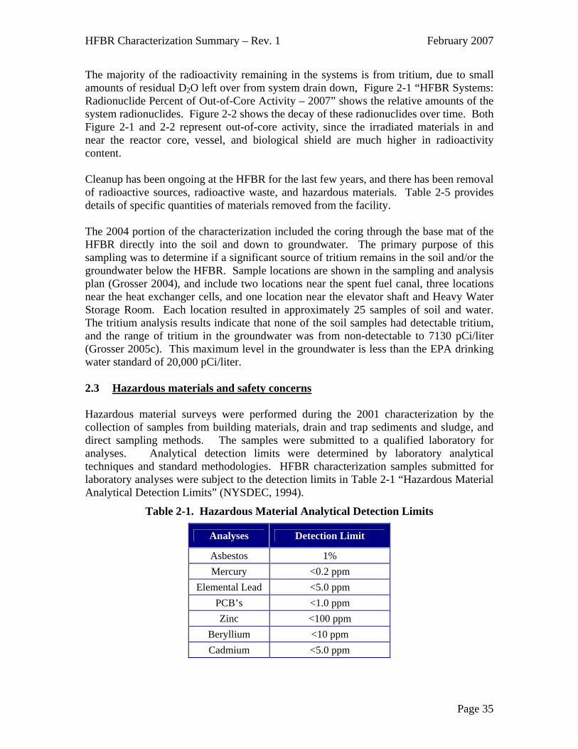
The majority of the radioactivity remaining in the systems is from tritium, due to small amounts of residual D2O left over from system drain down, Figure 2-1 “HFBR Systems: Radionuclide Percent of Out-of-Core Activity – 2007” shows the relative amounts of the system radionuclides. Figure 2-2 shows the decay of these radionuclides over time. Both Figure 2-1 and 2-2 represent out-of-core activity, since the irradiated materials in and near the reactor core, vessel, and biological shield are much higher in radioactivity content. Cleanup has been ongoing at the HFBR for the last few years, and there has been removal of radioactive sources, radioactive waste, and hazardous materials. Table 2-5 provides details of specific quantities of materials removed from the facility. The 2004 portion of the characterization included the coring through the base mat of the HFBR directly into the soil and down to groundwater. The primary purpose of this sampling was to determine if a significant source of tritium remains in the soil and/or the groundwater below the HFBR. Sample locations are shown in the sampling and analysis plan (Grosser 2004), and include two locations near the spent fuel canal, three locations near the heat exchanger cells, and one location near the elevator shaft and Heavy Water Storage Room. Each location resulted in approximately 25 samples of soil and water. The tritium analysis results indicate that none of the soil samples had detectable tritium, and the range of tritium in the groundwater was from non-detectable to 7130 pCi/liter (Grosser 2005c). This maximum level in the groundwater is less than the EPA drinking water standard of 20,000 pCi/liter. 2.3 Hazardous materials and safety concerns Hazardous material surveys were performed during the 2001 characterization by the collection of samples from building materials, drain and trap sediments and sludge, and direct sampling methods. The samples were submitted to a qualified laboratory for analyses. Analytical detection limits were determined by laboratory analytical techniques and standard methodologies. HFBR characterization samples submitted for laboratory analyses were subject to the detection limits in Table 2-1 “Hazardous Material Analytical Detection Limits” (NYSDEC, 1994).
Table 2-1. Hazardous Material Analytical Detection Limits
Analyses Detection Limit
Asbestos 1% Mercury <0.2 ppm
Elemental Lead <5.0 ppm PCB’s <1.0 ppm Zinc <100 ppm
Beryllium <10 ppm Cadmium <5.0 ppm
Page 35
HFBR Characterization Summary – Rev. 1 February 2007
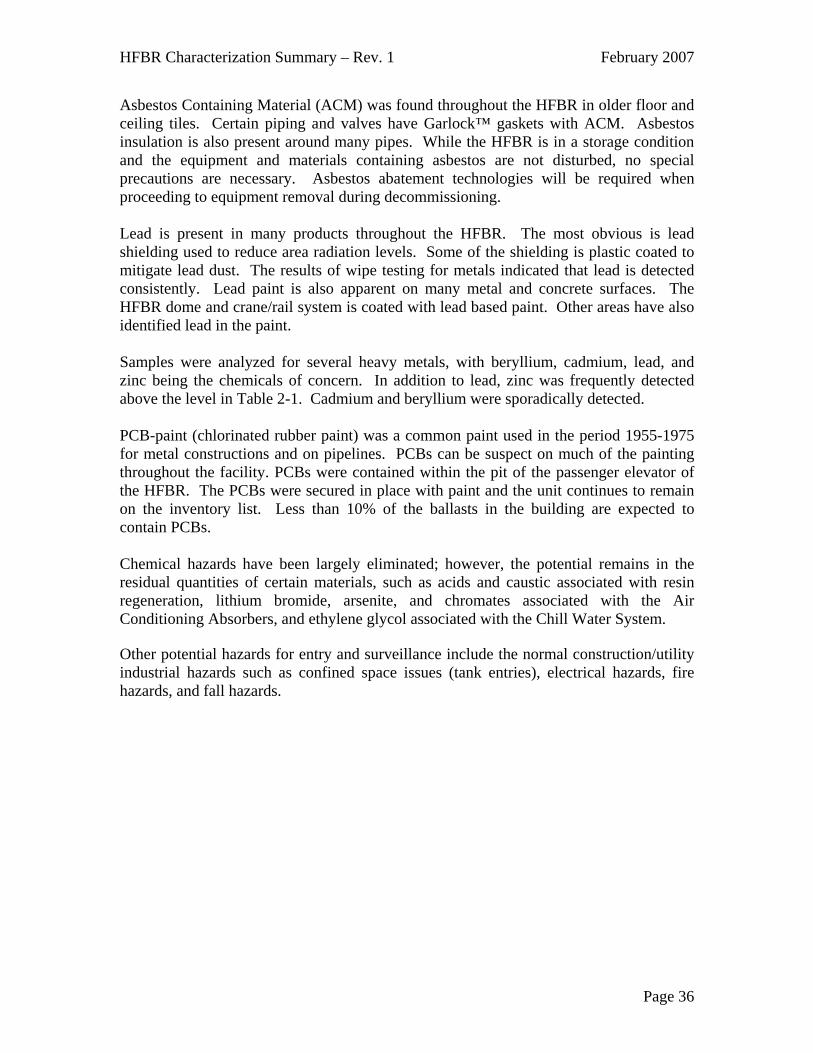
Asbestos Containing Material (ACM) was found throughout the HFBR in older floor and ceiling tiles. Certain piping and valves have Garlock™ gaskets with ACM. Asbestos insulation is also present around many pipes. While the HFBR is in a storage condition and the equipment and materials containing asbestos are not disturbed, no special precautions are necessary. Asbestos abatement technologies will be required when proceeding to equipment removal during decommissioning. Lead is present in many products throughout the HFBR. The most obvious is lead shielding used to reduce area radiation levels. Some of the shielding is plastic coated to mitigate lead dust. The results of wipe testing for metals indicated that lead is detected consistently. Lead paint is also apparent on many metal and concrete surfaces. The HFBR dome and crane/rail system is coated with lead based paint. Other areas have also identified lead in the paint. Samples were analyzed for several heavy metals, with beryllium, cadmium, lead, and zinc being the chemicals of concern. In addition to lead, zinc was frequently detected above the level in Table 2-1. Cadmium and beryllium were sporadically detected. PCB-paint (chlorinated rubber paint) was a common paint used in the period 1955-1975 for metal constructions and on pipelines. PCBs can be suspect on much of the painting throughout the facility. PCBs were contained within the pit of the passenger elevator of the HFBR. The PCBs were secured in place with paint and the unit continues to remain on the inventory list. Less than 10% of the ballasts in the building are expected to contain PCBs. Chemical hazards have been largely eliminated; however, the potential remains in the residual quantities of certain materials, such as acids and caustic associated with resin regeneration, lithium bromide, arsenite, and chromates associated with the Air Conditioning Absorbers, and ethylene glycol associated with the Chill Water System. Other potential hazards for entry and surveillance include the normal construction/utility industrial hazards such as confined space issues (tank entries), electrical hazards, fire hazards, and fall hazards.
Page 36
HFBR Characterization Summary – Rev. 1 February 2007
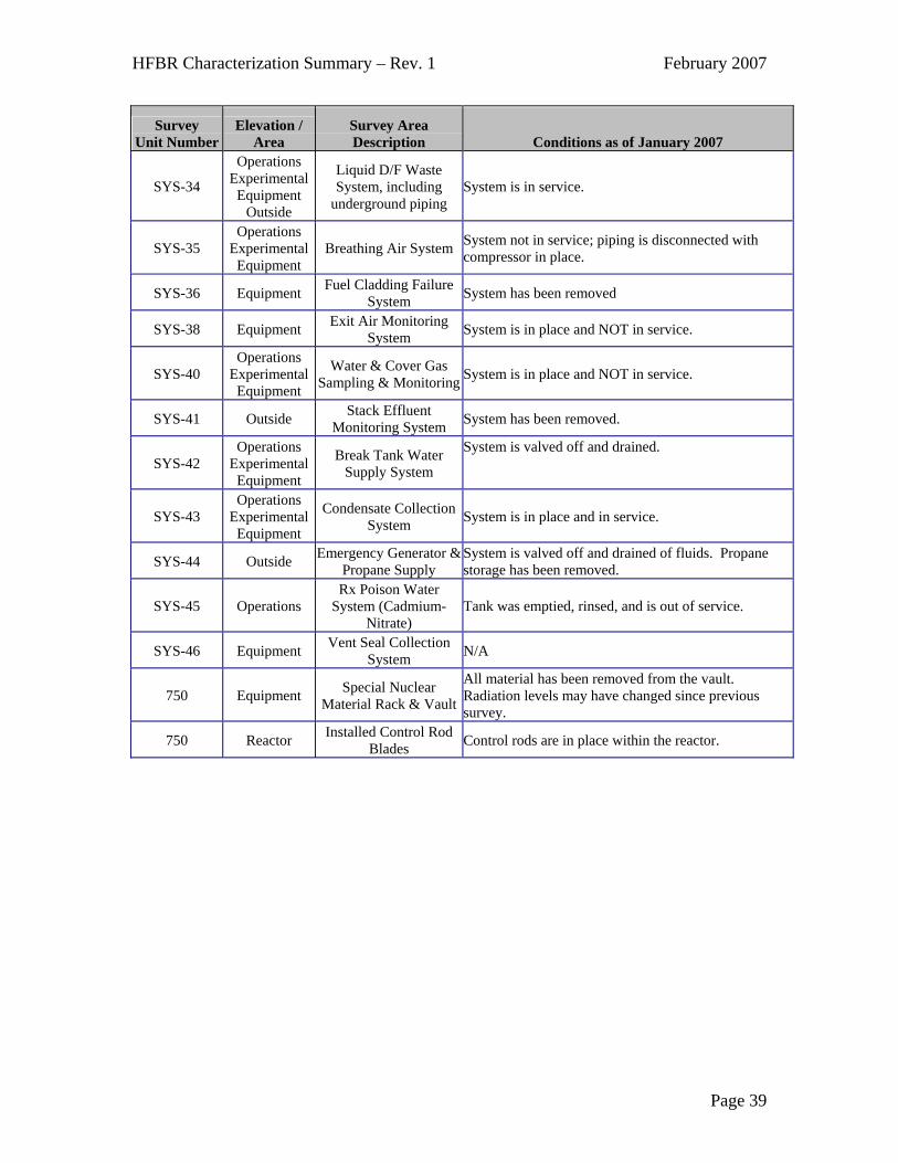
Table 2-2 HFBR Systems and Components
Survey
Unit Number Elevation /
Area Survey Area Description Conditions as of January 2007
SYS-01 Operations
Experimental Equipment
Primary Cooling Water System &
Instrumentation
System is drained; Reactor Vessel drained with helium blanket.
SYS-02 Equipment Primary Purification System
System and resin beds are drained, but resin remains in the vessels.
SYS-03 Equipment Primary Acidification System
System was drained, rinsed, and neutralized with NaOH, but the storage tank now contains semi-neutralized battery acid.
SYS-04 Equipment Primary Sampling System System is drained and blown down.
SYS-05 Equipment Primary Pump Seal Cold Trap System
System has been de-energized.
SYS-06
Equipment Experimental Operations
DA Drain & D2O Transfer System
System is drained.
SYS-08 Operations Reactor Vessel Cover
Gas System & Instrumentation
System is functioning.
SYS-09 Operations SPAM System
(Supplemental Poison Addition Method)
In 2001, system was partially removed. Flex hoses, piping and drums were removed from the isolation valve to the reactor on the operations level. The 6’ of piping closest to the Reactor Vessel is contaminated and will stay as an abandoned system.
SYS-10
Operations Experimental Equipment
Outside
Light Water Make Up System
In 2001, the system was partially removed, and the remaining parts were drained.
SYS-11 Operations
Experimental Equipment
Shutdown Cooling Water System & Instrumentation
System is drained and pumps are electrically disconnected.
SYS-12 Operations
Experimental Equipment
Thermal Shield Cooling Water System. & Instrumentation
System is drained, pumps disconnected, and valves shut.
SYS-13 Operations
Experimental Equipment
Biological Shield Cooling Water System
& Instrumentation
System is drained, valves shut, and electrical leads for pumps are lifted.
SYS-14 Equipment Canal Cooling Water System System is drained.
SYS-15 Equipment Auxiliary Water
Purification System BG201
System is drained; resin is removed, but charcoal remains in the purification system. Small amounts of Sodium Hydroxide and Hydrochloric Acid may be present.
SYS-16
Operations Experimental Equipment
Outside
Secondary Cooling Water System & Instrumentation
System is drained; tanks have been flushed and neutralized.
Page 37

HFBR Characterization Summary – Rev. 1 February 2007
Survey Elevation / Survey Area Unit Number Area Description Conditions as of January 2007
SYS-17 Outside Secondary Cooling Water Treatment
System
System was partially removed, and was drained, flushed, and partially neutralized. Chemical tanks are still present.
SYS-18
Operations Experimental Equipment
Outside
Building Ventilation System
System is in place and in use.
SYS-19 Equipment A/C Absorbers System is in place.
SYS-20 Operations
Experimental Equipment
Chill Water System System is in place.
SYS-21 Operations
Experimental Equipment
Hot Water Heating System
System is in place and in use.
SYS-22 Equipment Steam Heating System System is in place and in use.
SYS-23
Operations Experimental Equipment
Outside
Domestic Water System System is in place and in use.
SYS-24 Operations
Experimental Equipment
Sanitary System System is in place and in use.
SYS-25
Operations Experimental Equipment
Outside
Fire Protection System System is in place and is available for use.
SYS-26
Operations Experimental Equipment
Outside
Helium Supply System System is in place and is operational, providing a cover gas over the vessel
SYS-27 Outside Equipment
Carbon Dioxide Gas System
System is out of service; no CO2 remains in system.
SYS-28 Experimental Beam Tube Plugs and Cheese Box (storage)
Beam plug H-6 has been removed. Remaining beam plugs are awaiting disposal.
SYS-30 Operations Vertical Irradiation Thimbles
System is in place, and drained. High dose rates and contamination levels are on the system.
SYS-31 Operations Experimental
Experimental Facilities Cooling Water System
& Instrumentation System is not in service, and it is drained.
SYS-32 Experimental Equipment
Outside
Cold Neutron Facility and Systems Facility is out of service; equipment has been removed.
SYS-33
Operations Experimental Equipment
Outside
Building Compressed Air System System is in place and in service.
Page 38
HFBR Characterization Summary – Rev. 1 February 2007
Survey Elevation / Survey Area Unit Number Area Description Conditions as of January 2007
SYS-34
Operations Experimental Equipment
Outside
Liquid D/F Waste System, including
underground piping System is in service.
SYS-35 Operations
Experimental Equipment
Breathing Air System System not in service; piping is disconnected with compressor in place.
SYS-36 Equipment Fuel Cladding Failure System System has been removed
SYS-38 Equipment Exit Air Monitoring System System is in place and NOT in service.
SYS-40 Operations
Experimental Equipment
Water & Cover Gas Sampling & Monitoring System is in place and NOT in service.
SYS-41 Outside Stack Effluent Monitoring System System has been removed.
SYS-42 Operations
Experimental Equipment
Break Tank Water Supply System
System is valved off and drained.
SYS-43 Operations
Experimental Equipment
Condensate Collection System System is in place and in service.
SYS-44 Outside Emergency Generator & Propane Supply
System is valved off and drained of fluids. Propane storage has been removed.
SYS-45 Operations Rx Poison Water
System (Cadmium-Nitrate)
Tank was emptied, rinsed, and is out of service.
SYS-46 Equipment Vent Seal Collection System N/A
750 Equipment Special Nuclear Material Rack & Vault
All material has been removed from the vault. Radiation levels may have changed since previous survey.
750 Reactor Installed Control Rod Blades Control rods are in place within the reactor.
Page 39
HFBR Characterization Summary – Rev. 1 February 2007
Table 2-3 HFBR Elevation and Structure Survey Areas
Survey Unit Number Elevation / Area Survey Area Description
BAL-01 Balcony Offices B-6 to B-14 BAL-02 Balcony Mens / Ladies Room BAL-03 Balcony Office B-4 & B-5 BAL-04 Balcony Walkways BAL-05 Balcony Walls in open area BAL-06 Balcony Pipes in open area BAL-07 Balcony Ceiling in open area BAL-08 Balcony Crawl Space LOB-01 Lobby Lobby, Conference Room, office OPS-01 Operations Rx Group Offices (Leader/ass't leader/secretary) OPS-02 Operations Day Crew shop area OPS-03 Operations OPS Bullpen OPS-04 Operations Water Chemistry Laboratory (2 rooms) OPS-05 Operations RMG Hot Shop OPS-06 Operations Research Coordination Group Area OPS-07 Operations Dome OPS-08 Operations Crane OPS-09 Operations Trenches/Pipe trays OPS-10 Operations RMA above WCL OPS-11 Operations Iodine Sample Prep/Counting Area OPS-12 Operations Walkway behind South Stairwell OPS-13 Operations Custodians Area (behind North Stairwell) OPS-14 Operations Walkway behind locker room OPS-15 Operations Locker Room OPS-16 Operations Bridge from Rx top to control room OPS-17 Operations Control Room - Mens room OPS-18 Operations RIG Areas OPS-19 Operations Hutch OPS-20 Operations Dry box OPS-21 Operations Greenhouse OPS-22 Operations Top of Greenhouse OPS-23 Operations Security Observation Stations OPS-24 Operations General Walkways OPS-25 Operations Emergency Hatch Area OPS-26 Operations Reactor Top
Page 40

HFBR Characterization Summary – Rev. 1 February 2007
Survey Unit Number Elevation / Area Survey Area Description
OPS-27 Operations Reactor Pit (Upper and Lower) OPS-28 Operations Stairwells (North and South) OPS-29 Operations Offices (WCL, Day Crew Supervisors, HP) OPS-30 Operations Positron Blockhouse EXP-01 Experimental Mens Room EXP-02 Experimental L-2 EXP-03 Experimental L-4 EXP-04 Experimental L-6 & L-7 EXP-05 Experimental L-8 & L-9 EXP-06 Experimental L-9B & L-10 EXP-07 Experimental L-10B EXP-08 Experimental L-11 & L-11A EXP-09 Experimental L-12 & L-13 EXP-10 Experimental L-14 & L-15 EXP-11 Experimental L-16 EXP-12 Experimental Cheesebox
EXP-13 Experimental H-1 trench to H-8 trench (floor) Not completed due to beam plug removal project
EXP-14 Experimental H-7 trench to H-6 trench (floor) Not completed due to beam plug removal project
EXP-15 Experimental H-5 trench to H-4 trench (floor) Not completed due to beam plug removal project
EXP-16 Experimental H-9 trench to H-3 trench (floor) Not completed due to beam plug removal project
EXP-17 Experimental H-2 trench to trench (floor) Not completed due to beam plug removal project
EXP-18 Experimental C1 to C2 (floor) EXP-19 Experimental C2 to C3 (floor) EXP-20 Experimental C3 to C4 (floor) EXP-21 Experimental C4 to C5 (floor) EXP-22 Experimental C5 to C6 (floor) EXP-23 Experimental C6 to C7 (floor) EXP-24 Experimental C7 to C8 (floor) EXP-25 Experimental C8 to C10 (floor) EXP-26 Experimental C10 to C11 (floor) EXP-27 Experimental C11 to C12 (floor) EXP-28 Experimental C12 to C13 (floor) EXP-29 Experimental C13 to C14 (floor) EXP-30 Experimental C14 to C15 (floor)
Page 41
HFBR Characterization Summary – Rev. 1 February 2007
Survey Unit Number Elevation / Area Survey Area Description
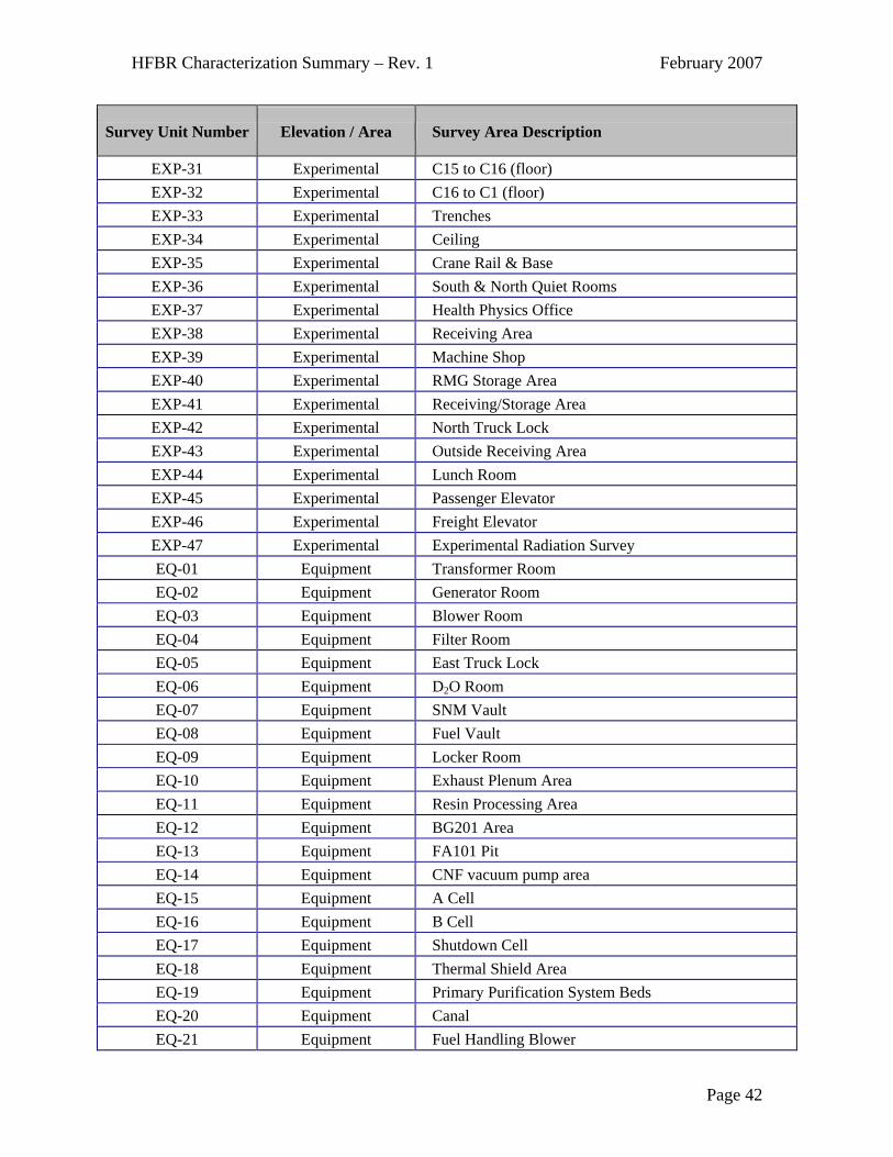
EXP-31 Experimental C15 to C16 (floor) EXP-32 Experimental C16 to C1 (floor) EXP-33 Experimental Trenches EXP-34 Experimental Ceiling EXP-35 Experimental Crane Rail & Base EXP-36 Experimental South & North Quiet Rooms EXP-37 Experimental Health Physics Office EXP-38 Experimental Receiving Area EXP-39 Experimental Machine Shop EXP-40 Experimental RMG Storage Area EXP-41 Experimental Receiving/Storage Area EXP-42 Experimental North Truck Lock EXP-43 Experimental Outside Receiving Area EXP-44 Experimental Lunch Room EXP-45 Experimental Passenger Elevator EXP-46 Experimental Freight Elevator EXP-47 Experimental Experimental Radiation Survey EQ-01 Equipment Transformer Room EQ-02 Equipment Generator Room EQ-03 Equipment Blower Room EQ-04 Equipment Filter Room EQ-05 Equipment East Truck Lock EQ-06 Equipment D2O Room EQ-07 Equipment SNM Vault EQ-08 Equipment Fuel Vault EQ-09 Equipment Locker Room EQ-10 Equipment Exhaust Plenum Area EQ-11 Equipment Resin Processing Area EQ-12 Equipment BG201 Area EQ-13 Equipment FA101 Pit EQ-14 Equipment CNF vacuum pump area EQ-15 Equipment A Cell EQ-16 Equipment B Cell EQ-17 Equipment Shutdown Cell EQ-18 Equipment Thermal Shield Area EQ-19 Equipment Primary Purification System Beds EQ-20 Equipment Canal EQ-21 Equipment Fuel Handling Blower
Page 42

HFBR Characterization Summary – Rev. 1 February 2007
Survey Unit Number Elevation / Area Survey Area Description
EQ-22 Equipment Overhead Piping EQ-23 Equipment Shutdown Pump Area EQ-24 Equipment RMG Hot Shop EQ-25 Equipment Ceiling EQ-26 Equipment Equipment Room (outside of building) EQ-27 Equipment Decontamination Sink Area EQ-28 Equipment Equipment Level Radiation Survey EQ-29 Equipment SNM & Fuel Vaults
Page 43
HFBR Characterization Summary – Rev. 1 February 2007
Table 2-4 HFBR System Radioactivity Calculation Summary
System System DescriptionH-3 (Ci)
Co-60 (Ci)
Fe-55 (Ci)
Ni-63 (Ci)
Cs-137 (Ci)
Total Ci in 2007
Total Ci in 2057
Total Ci in 2107
SYS-01Primary Coolant Water System 34.84 0.04 0.06 0.02 0.01 35.0 2.1 0.1
SYS-02 Primary System Purification 10.54* 0.06 0.13 0.02 0.00 0.2 0.0 0.0
SYS-04 Primary Sampling System Note 1 0.00 0.00 0.00 0.00 0.0 0.0 0.0
SYS-05Primary Pump Seal Cold Trap System Note 1 0.00 0.00 0.00 0.00 0.0 0.0 0.0
SYS-06DA Drain & D20 Transfer System Note 1 0.00 0.01 0.00 0.00 0.0 0.0 0.0
SYS-08Reactor Vessel Cover Gas System Note 1 0.00 0.00 0.00 0.00 0.0 0.0 0.0
SYS-11 Shutdown Cooling System Note 1 0.03 0.04 0.02 0.00 0.1 0.0 0.0
SYS-12Thermal Shield Cooling System Note 1 0.04 0.06 0.02 0.01 0.1 0.0 0.0
SYS-15Auxiliary Water Purification System Note 1 0.00 0.00 0.00 0.00 0.0 0.0 0.0
SYS-31Experimental Facilities Cooling System Note 1 0.20 0.31 0.11 0.04 0.7 0.1 0.1
SYS-34 Liquid D/F Waste Systems 0.53 0.78 1.20 0.43 0.14 3.1 0.4 0.2
Misc Miscellaneous Hot Spots 0.00 0.57 0.90 0.32 0.00 1.8 0.2 0.2
MiscMiscellaneous Systems associated with Note 2 3.54 0.17 0.27 0.09 0.02 4.1 0.3 0.1
Total for All Systems 38.9 1.9 3.0 1.0 0.2 45.1 3.1 0.7
Note 1: D20 was drained from systems, but 10 gallons is assumed to be present as residual in various systems. This H-3 activity is included in the Primary Cooling Water System.
Note 2: Several low activity systems were assumed to add up to a combined 10% of the total plant activity, exclusive of the reactor vessel and internals.
Note that Beam Plugs and resin in various systems are not part of this total.
The Vertical Irradiation Tubes are part of the in-vessel activity determination
Page 44

HFBR Characterization Summary – Rev. 1 February 2007
Ni-63 2%
Cs-1370.5%
Fe-55 6.7%
Co-604.2%
H-3 87%
Total = 38.9 Ci in 2007
Figure 2-1. HFBR Systems: Radionuclide Percent of Out-of-Core Activity- 2007
0
5
10
15
20
25
30
35
40
45
50
2007
2017
2027
2037
2047
2057
2067
2077
2087
2097
2107
Year
HFB
R S
yste
ms
Act
ivity
- C
urie
s
Figure 2-2. HFBR Systems: Total Out-of-Core Activity- 100 year Decay
Page 45
HFBR Characterization Summary – Rev. 1 February 2007
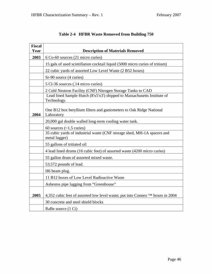
Table 2-4 HFBR Waste Removed from Building 750
Fiscal Year Description of Materials Removed 2003 6 Co-60 sources (21 micro curies)
15 gals of used scintillation cocktail liquid (5000 micro curies of tritium) 22 cubic yards of assorted Low Level Waste (2 B52 boxes) Sr-90 source (4 curies) 5 Cl-36 sources (.14 micro curies) 2 Cold Neutron Facility (CNF) Nitrogen Storage Tanks to CAD
Lead lined Sample Hutch (8'x5'x3') shipped to Massachusetts Institute of Technology.
2004 One B12 box beryllium filters and ganiometers to Oak Ridge National Laboratory
20,000 gal double walled long-term cooling water tank. 60 sources (~1.5 curies)
35 cubic yards of industrial waste (CNF storage shed, MH-1A spacers and metal lugger)
55 gallons of tritiated oil 4 lead lined drums (16 cubic feet) of assorted waste (4200 micro curies) 55 gallon drum of assorted mixed waste. 53,572 pounds of lead. H6 beam plug. 11 B12 boxes of Low Level Radioactive Waste Asbestos pipe lagging from “Greenhouse”
2005 4,352 cubic feet of assorted low level waste; put into Connex ™ boxes in 2004 30 concrete and steel shield blocks RaBe source (1 Ci)
Page 46
HFBR Characterization Summary – Rev. 1 February 2007
3. Part 3. HFBR Characterization Summary - Ancillary/Support Facilities and Soil Characterization
3.1 Summary of Ancillary/Support Facilities
The HFBR facilities considered here include: Building 704 Fan House and associated Exit Air Facility; Building 705 Stack and associated Pedestal and Underground Plenum; Building 715 Stack Monitoring Facility; and D/F-Waste Line. A brief description of these facilities is provided in the overview section of this report.
3.2 Previous Characterizations for Ancillary/Support Facilities and Soil A specific list of the ancillary/support facilities associated with the HFBR was derived from the “Brookhaven National Laboratory High Flux Beam Reactor – Final Characterization Report, (Cabrera 2001b) and “High Flux Beam Reactor and Balance of Plant Structures Preliminary Assessment/Site Inspection (Work Plan, Sampling and Analysis Plan, Health and Safety Plan, Waste Management Plan)”, (Grosser 2001). Based on a review of these reports, a scope of work was developed for further Site Inspection (SI) activities. The Preliminary Assessment (PA) identified issues that had the potential to impact surface or subsurface soils, and ultimately groundwater, and classified them as Areas of Interest (AOIs). A total of 27 AOIs associated with the HFBR project were identified. The results of the SI actions associated with these AOIs were published in the document “High Flux Beam Reactor and Balance of Plant Structures Preliminary Assessment/Site Inspection Report, Final”, which was issued as Final in 2005 (Grosser 2005a). Of the 27 AOIs investigated throughout the HFBR complex, 23 were eliminated as AOIs and four warranted additional action. No Areas of Concern (AOCs) were identified. It was established that radiological results for all AOIs, other than the four warranting further investigation; all fell within the Preliminary Remediation Goals (PRGs) -50 Years Criteria. In May 2004, a gap analysis was performed to determine where fill-in data was required. It was determined that additional characterization was needed for:
o Building 705 Exit Air Facility and Stack o Building 704 Fan House and Below Ground Duct o Surrounding soils (surface and deep soils): Buildings 704 and 715
A program of coring/sampling and analysis was performed in and around these buildings from September through December 2004. The results of this characterization effort are documented in data packages on file with Environmental Management. The results of the work performed in and around Building 705 Stack, including work performed in 2001,
Page 47

HFBR Characterization Summary – Rev. 1 February 2007
are documented in the report “Building 705 Stack Resolution of End-State, February 2005” (Grosser 2005b). 3.3 Characterization Results for Ancillary/Support Facilities and Soil
Figure 3-1. Building 704 Fan House The Fan House was constructed in 1950 and was originally designed to support operations at the Brookhaven Graphite Research Reactor (BGRR). Following shutdown of the BGRR, the Fan House was designated as an HFBR Balance of Plant System since it housed electrical switchgear for AC and DC power to the HFBR, as well as for Buildings 701 and 703. The building housed five primary fans and a secondary fan, which took suction through ducts that penetrated the roof and connected to the above ground duct bottom. These fans discharged into a below grade exhaust duct directly below the fan compartments. Presently, the below grade duct is still intact, running under and along the northern portion of the building in the basement. As a result of past operations, the Fan House is a radiological controlled area. Building 704 – Fan House: Characterization Notes: Item 1: Sampling performed in the basement of Building 704 has identified a location on the soil floor containing radionuclides above the cleanup criteria. The sample was collected at a zero to six-inch depth at a location designated as AOI 006-02. Results from
Page 48

HFBR Characterization Summary – Rev. 1 February 2007
this sample location indicated elevated levels of cesium-137 and strontium-90. Contamination at this location was likely the result of water leaking through the floor seams of the fan cell above. Results from the 4.5 to 5.0 foot sample depth met cleanup criteria. It was recommended that limited soil remediation at this location be performed, with endpoint sample collection. Item 1 Results: The results are shown in Table 3-1 and indicate that there is Sr-90 contamination in the Secondary Air Fan Cell and in Fan Cell 3 (Grosser 2005c). The gross beta results in those two locations are also indicative of the potential for other radionuclides, likely to be Cs-137 based on the history of what has been detected in the stack.
Table 3-1 Building 704 – Soil Core Samples in Fan Cells – Results
Location Sr-90
(pCi/g) H-3
(pCi/g) Gross Alpha
(pCi/g) Gross Beta
(pCi/g)
704-Sec. Air Fan Cell 92 <MDA 3.7 270 Fan Cell 3-AB 17 <MDA <MDA 415 Fan Cell 3-CD 5.3 <MDA <MDA 45
Fan Cell 5 2.1 <MDA <MDA 18 Surface Soil Cleanup
Criteria 15 1010 N/A N/A
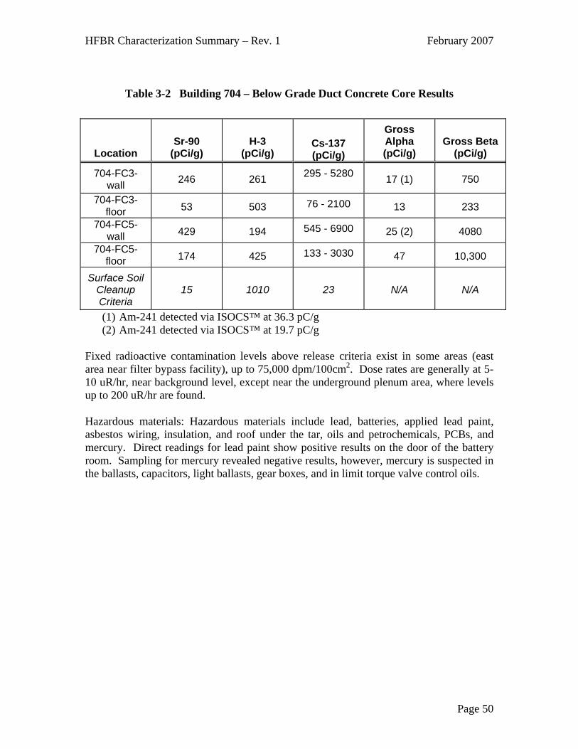
Item 2: The Below Grade Exhaust Duct carried exhaust from the fan cells to Building 705 (Stack). Two locations in the concrete duct were sampled; floor and wall samples were taken at each location. The locations were chosen to be next to expansion joints. Item 2 Results: The results are shown in Table 3-2, “Building 704 – Below Grade Duct Concrete Core Results”, and indicate that there is Sr-90 contamination and other non-specific beta contamination. ISOCS™ results indicated Cs-137 up to 6900 pCi/g and Am-241 up to 36 pCi/g in the duct. Low levels of tritium were also detected. (Grosser 2005c)
Page 49
HFBR Characterization Summary – Rev. 1 February 2007
Table 3-2 Building 704 – Below Grade Duct Concrete Core Results
Location Sr-90
(pCi/g) H-3
(pCi/g) Cs-137 (pCi/g)
Gross Alpha (pCi/g)
Gross Beta (pCi/g)
704-FC3-wall 246 261 295 - 5280 17 (1) 750
704-FC3-floor 53 503 76 - 2100 13 233
704-FC5-wall 429 194 545 - 6900 25 (2) 4080
704-FC5-floor 174 425 133 - 3030 47 10,300
Surface Soil Cleanup Criteria
15 1010 23 N/A N/A
(1) Am-241 detected via ISOCS™ at 36.3 pC/g (2) Am-241 detected via ISOCS™ at 19.7 pC/g
Fixed radioactive contamination levels above release criteria exist in some areas (east area near filter bypass facility), up to 75,000 dpm/100cm2. Dose rates are generally at 5-10 uR/hr, near background level, except near the underground plenum area, where levels up to 200 uR/hr are found. Hazardous materials: Hazardous materials include lead, batteries, applied lead paint, asbestos wiring, insulation, and roof under the tar, oils and petrochemicals, PCBs, and mercury. Direct readings for lead paint show positive results on the door of the battery room. Sampling for mercury revealed negative results, however, mercury is suspected in the ballasts, capacitors, light ballasts, gear boxes, and in limit torque valve control oils.
Page 50

HFBR Characterization Summary – Rev. 1 February 2007
Figure 3-2. Building 705 – Stack
Building 705 – Stack: Characterization Notes: Radiological characterization work of the stack has taken place over several years, and is documented in the “Building 705 Stack Resolution of End-State, February 2005” (Grosser 2005b). A summary of the characterization results is shown below:
• 2001: Smears of the interior lower portion of the stack (the base near the plenum inlet). These smears indicated removable contamination up to 22,000 dpm/100 cm2. Cs-137 was identified in the results.
• 2001: Soil samples collected from excavations around the stack were analyzed
using gamma spectroscopy, and Cs-137 was detected slightly above background levels in three out of nine samples. The highest sample result was 6.4 pCi/g, which is below the BNL-specific criteria of 23 pCi/g for Cs-137.
• 1997 – 2004: Characterization data for water samples collected from the stack
drain during the period of 1997 though 2004 were analyzed for gross alpha/beta levels and tritium and Cs-137 activities. Strontium-90 analysis was performed for 2003 and 2004. The results reveal that water samples collected from the stack drain system are in excess of NYSDEC ambient water quality standards.
• 1999: A radiological characterization effort was conducted on the buried
interconnecting ducts between Buildings 801, 802, 811, 815 and 830, all of
Page 51

HFBR Characterization Summary – Rev. 1 February 2007
which discharge to the 705 Stack. This characterization was qualitative in nature, but determined that the following ducts were contaminated:
o Duct between Building 801 and Building 811 (10” diameter, cast iron) o Duct between Building 801 and Building 802 (42” diameter, concrete)
2004: During December 2004, a characterization effort was performed that involved collecting core samples at various heights around the stack perimeter. Three concrete cores were collected from four different elevations: one set from the pedestal, one set from 10" above the top of the pedestal (elev. 145.5'), one set at the lowest platform (elev. 225.5'), and one set from the middle platform (elev. 333'). No concrete cores were collected at the upper platform (elev. 433'). The concrete cores were sampled and analyzed for radiological contamination on the interior surfaces and to determine the depth that contamination has penetrated into the concrete. Table 3-3 below provides the sample locations, contamination penetration depths, and average concentrations of radionuclides present. (BNL 2004a, BNL 2004b, and BNL 2004c) The table includes a comparison to the surface soil cleanup criteria used for remediation of soils, based on precedence at BNL for Sr-90 and Cs-137. The concentrations have been decayed to January 2007.
Table 3-3 Stack Concrete Core Analytical Results
LocationPenetration Depth (inch)
Sr-90 (pCi/g) H-3 (pCi/g)
Cs-137 (pCi/g)
Pedestal 0.25 462 104 1154
Pedestal 0.50 86 86 62
Elev. 145.5' 0.25 58 25 333
Elev. 225.5' 0.25 174 45 425
Elev. 225.5' 0.50 51 25 13
Elev. 225.5' 0.75 36 21 6
Elev. 333' 0.25 187 50 629
Elev. 333' 0.50 16 191 3
Gross Average Concentration N/A 134 68 328
Surface Soil Cleanup Criteria N/A 15 1010 23
The “gross average concentration” is only used as an indicator to compare to the surface soil cleanup criteria, and does not represent the actual concentration over the entire stack. The concentrations of Sr-90 and Cs-137 on the contaminated stack surfaces (the first one
Page 52

HFBR Characterization Summary – Rev. 1 February 2007
half inch) are above the surface soil cleanup criteria; however, if the concentration were averaged over the entire weight of the stack concrete, the values would be less than the cleanup criteria. It is estimated that the total Curie content present in the Building 705 Stack concrete is about 28 millicuries in January 2007, as shown in Table 3-4.
Table 3-4 Estimated Surface Activity in Building 705 Stack
2007 2017 2027 2057 2082 2107
NuclideHalf-Life
(yr) Stack mCi Stack mCi Stack mCi Stack mCi Stack mCi Stack mCiSr-90 28.8 18.6 14.6 11.5 5.6 3.0 1.7
Cs-137 30.1 7.2 5.7 4.5 2.3 1.3 0.7H-3 12.3 2.7 1.5 0.9 0.2 0.0 0.0
Total N/A 28 22 17 8 4 2
Years Decay N/A 0 10 20 50 75 100
Figure 3-3. Building 715 – Stack Monitoring Facility
Building 715 – Stack Monitoring Facility Characterization Notes: Surveys of radiation and radiological contamination within the building indicate background levels. There had been indications of contaminated soil based on previous characterization; therefore, additional soil samples were taken in 2004 to determine if remediation was necessary. Three samples were taken in November and December of 2004 at depths of 0-2 feet and 2-4 feet. Samples were analyzed for gross alpha, gross beta, Sr-90, tritium, and gamma spectroscopy. All samples were consistent with background radioactivity, and no reactor related radionuclides were detected (BNL, 2005a).
Page 53

HFBR Characterization
Summary – Rev. 1 February 2007
Page 54
Figure 3-4. Building 751 – Cold Neutron Facility
Building 751 – Cold Neutron Facility Characterization Notes: Surveys of radiation and radiological contamination within the building indicate background levels. The CNF has been surveyed and released from radiological controls; it is no longer considered part of the HFBR facility. Hazardous materials include solvents, degreasers, lubricants, oils and petrochemicals, and lead shielding. The hazardous materials are associated with equipment, such as motors and compressors with contained fluid. When this equipment is removed, the source of the hazardous materials will be removed (Cabrera, 2001b). D/F-Waste Line: The liquid waste system provided a means of storage and disposal of potentially contaminated liquid wastes, including spilled heavy water. "D" wastes were pumped from the D/F Storage tank on the equipment level of the HFBR to the BNL waste treatment area where it was distilled with the distillate being solidified in waste disposal vaults. The portion of the D/F-Waste Line under consideration in this section that outside the HFBR confinement, and the line consists of about 1,117 feet of double-walled (2” within 4”) carbon steel pipe that runs between Buildings 750 and 801. Figure 3-5 shows the general location of the pipe as it leaves the HFBR.
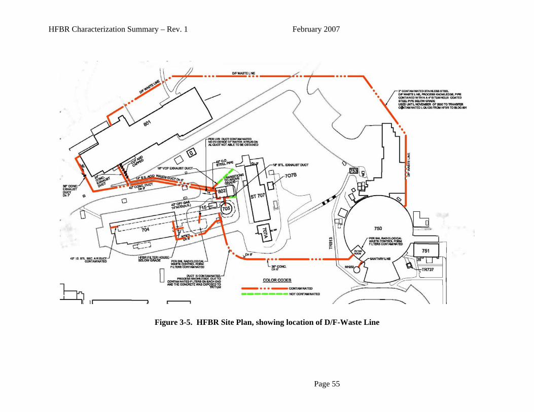
HFBR Characterization
Summary – Rev. 1 February 2007
Page 55
Figure 3-5. HFBR Site Plan, showing location of D/F-Waste Line

HFBR Characterization Summary – Rev. 1 February 2007
4. References
The references listed below were directly cited in the HFBR Characterization Summary Report: 1. (BNL 1964) Final Safety Analysis Report for the Brookhaven High Flux Beam
Research Reactor, 1964.
2. (BNL 1996) HFBR Plant Description Manual, Reactor Division, Brookhaven National Laboratory, HFBR-PDM-T, October 1996.
3. (BNL 2004a) HFBR: Characterization Coring & Sampling Program FY 2004-FY 2005, Sample Analysis Data for Stack, 2004.
4. (BNL 2004b) HFBR: Characterization Coring & Sampling Program FY 2004-FY 2005, ISOCS Data for Stack, Volume 1 of 2, 2004.
5. (BNL 2004c) HFBR: Characterization Coring & Sampling Program FY 2004-FY 2005, ISOCS Data for Stack, Volume 2 of 2, 2004.
6. (Cabrera 2001a) High Flux Beam Reactor Characterization Project Plan, Cabrera Services, Inc., March 2001.
7. (Cabrera 2001b) Brookhaven National Laboratory High Flux Beam Reactor – Final Characterization Report, Cabrera Services, Inc., September 2001.
8. (Cheng 2007) Technical Review of HFBR Activation Analysis Performed by WMG, Inc., L. Cheng and A. Aronson, February 9, 2007.
9. (DAQ 2004) High Flux Beam Reactor Systems and Building Characterization and End Point Review, DAQ, Inc., December 2004.
10. (DAQ 2005) High Flux Beam Reactor Systems and Components Activity Calculation, DAQ, Inc., February 2005.
11. (Grosser 2001) High Flux Beam Reactor and Balance of Plant Structures, Preliminary Assessment/Site Inspection: Work Plan; Sampling and Analysis Plan; Health and Safety Plan; Waste Management Plan, P.W. Grosser Consulting, Inc., August 2001.
12. (Grosser 2004) HFBR: Building 750 Floor Mat and Groundwater Sampling and Analysis Plan, P.W. Grosser Consulting, Inc., October 8, 2004.
13. (Grosser 2005a) High Flux Beam Reactor and Balance of Plant Structures Preliminary Assessment/Site Inspection Report, Final, P.W. Grosser Consulting, Inc., January 2005.
14. (Grosser 2005b) Building 705 Stack Resolution of End-State, P.W. Grosser Consulting, Inc., February 2005
15. (Grosser 2005c) HFBR and Balance of Plant Supplemental Characterization Summary Report, P.W. Grosser Consulting, Inc., June 2005.
Page 56

HFBR Characterization Summary – Rev. 1 February 2007
16. (KAPL 2002) Nuclides and Isotopes, Chart of the Nuclides, 16th Edition, Knolls Atomic Power Laboratory, Inc., 2002.
17. (NYSDEC 1994) HWR-94-4047, TAGM Limits, memo from NY State Department of Environmental Conservation, January 1994.
18. (Tichler 1995) Memorandum from Paul Tichler, Estimates of Neutron Activation in the HFBR Reactor Vessel, Vessel Internals and the Thermal Shield and Biological Shield, January 25, 1995.
19. (WMG 2007a) Final Characterization of the BNL HFBR Main Control Rods, WMG Calculation 6117-CA-054, Rev. 2A, 1/16/2007.
20. (WMG 2007b) Final Characterization of the BNL HFBR Auxiliary Control Rods, WMG Calculation 6117-CA-055, Rev. 1/15/2007.
21. (WMG 2007c) Final Characterization for Brookhaven National Laboratory High Flux Beam Reactor, WMG Report 6117-RE-072, WMG, Inc., February 2007.
Page 57