characterization of flip chip bump failure modes using high ...

NASA Technical Memorandum 102371
Characterization of Failure Processes in
Tungsten Copper Composites UnderFatigue Loading Conditions
Yong-Suk Kim, Michael J. Verrilli, and Timothy P. GabbLewis Research Center
Cleveland, Ohio
Prepared for theInternational Symposium for Testing and Failure Analysis (ISTFA '89)
sponsored by ASM International
Los Angeles, California, November 6-10, 1989
t.¢ :,.. ] "
https://ntrs.nasa.gov/search.jsp?R=19900011807 2018-07-09T03:46:46+00:00Z

Trade names or nlanuI'aclurers' names aie used in Ibis _eporl for idcnlification
only. This usage does not constilule an official cndorscnlem, eilher e_,pre,,,,ed or
implied, b} Ihe National Aeronaulics and .Space 'Ndmini,,tTali,an.

CHARACTERIZATION OF FAILURE PROCESSES IN TUNGSTEN COPPER
COMPOSITES UNDER FATIGUE LOADING CONDITIONS
Yong-Suk Kim*, Michael J. Verrilli, and Timothy P. GabbNational Aeronautics and Space Administration
Lewis Research CenterCleveland, Ohio 44135
SUMMARY
A fractographic and metallographic investigation was performed on speci-mens of a tungsten-fiber-reinforced copper matrix composite (9 vol %), whichhad experienced fatigue failures at elevated temperatures. The aim of thestudy was to determine major failure modes and possible failure mechanisms,with an emphasis placed on characterizing fatigue damage accumulation. Metal-lography of specimens fatigued under isothermal cyclic loading suggested thatfatigue damage initiates in the matrix. Cracks nucleated within the coppermatrix at grain boundaries, and they propagated through cavity coalescence.The growing cracks subsequently interacted with the reinforcing tungsten fib-ers, producing a localized ductile fiber failure. Examinations of interruptedtests before final failure confirmed the suggested fatigue damage processes.
INTRODUCTION
Many high-temperature engineering applications require the use of materi-als with specialized properties such as increased toughness, stiffness,strength, fatigue resistance, and use temperature. Continuous-fiber-reinforcedmetal matrix composites are among these advanced high-temperature materialsbecause they can be used under high-temperature conditions without significantloss of stiffness. Since metal matrix composite materials are targeted foruses in critical engineering components, prediction of durability is a crucialrequirement. An understanding of the dominant failure mechanism is indispensa-ble for the proper prediction of lifetime. However, the failure mechanisms ofcomposite materials are not sufficiently understood yet, especially undercyclic-loading conditions at high temperatures.
Currently a Cu alloy is used as a combustion chamber liner material forthe space shuttle main engine. The large temperature gradient within the linerduring a rocket launch causes large, thermally induced, cyclic plastic deforma-tion of the liner material. For improved durability in this application, NASALewis Research Center personnel are considering a tungsten-fiber-reinforcedcopper composite (W/Cu) as a substitute material. Therefore the high-temperature fatigue properties of this material are being characterized.
Fiber-reinforced composite materials can be generally categorized intothree types: (1) brittle fibers in a brittle matrix, (2) brittle fibers in aductile matrix, and (3) ductile fibers in a ductile matrix. The operative
*National Research Council - NASA Research Associate.

failure mechanismsof composites generally vary from category to category.The tungsten-fiber-reinforced copper composite is a ductile-ductile type mate-rial. Manyresearchers have used this system as a model composite materialbecauseof the strong and stable interface between its composite constituentsand the relative ease with which it is manufactured (refs. 1 to I0). However,most past work on this composite system has dealt with room temperature defor-mation behavior (refs. 3 to 6), elevated temperature tensile response (ref. 7),and simple thermal cycling effects (refs. 1,2,8, and 9). Cyclic test resultsof the composite at high temperatures are rare, and failure mechanismsundersuch loading conditions have seldom been reported (ref. I0).
This paper presents preliminary results of ongoing research on the W/Cu
composite and focuses on evaluating the failure mechanisms of the composite Inisothermal fatigue at temperatures of 533 and 833 K. The results obtained
through fractographic analyses with SEM and optical microscopy are reportedalong with a characterization of outside surface damage. Detailed mechanical
results of fatigue tests of the composite are reported in another paper(ref. If).
EXPERIMENTAL PROCEDURES
Material and Specimen
The W/Cu composite used in this study was manufactured by WestinghouseElectric Corporation (Pittsburgh, PA) through an arc-spraying technique(ref. 12). The matrix material was an oxygen-free, high-conductivity (OFHC)copper (99.95 wt % Cu) with 200-_m-diameter G.E. 218 tungsten wires used asthe reinforcing fiber. The as-received composite was a thin plate (2.54 mmthick) composed of four plies of W/Cu monotapes. The fiber volume fractionmeasured in all test specimens was 9±0.5 vol %. Rectangular cross-section spe-cimens (fig. I) were machined dlrectly from the as-received composite plate byusing electrodischarge machining. Specimens tested in the present work haveonly one orientation: all fibers are aligned parallel to the loadingdirection.
MECHANICAL TESTING
Fatigue tests were carried out with a closed-loop-servo-hydraulic machineat 533 and 833 K in a vacuum of 10-6 torr. The cyclic loading used a triangu-
lar wave form at a frequency of 3 cpm. All tests were performed in a load con-trol mode with an approximate R ratio (minimum load/maximum load) of 0.05.
Most of the specimens were cycled to complete failure, but some were inter-
rupted before failure in order to examine the evolution of the fatigue damage.
Further information on the fatigue tests is provided in another paper(ref. ll).
In order to differentiate between creep and fatigue processes in the fail-ure of the composite, several monotonic creep tests were also performed.Constant-load, creep-rupture tests were performed in vacuum at 533 K. Aftercreep rupture, the fracture surfaces and cross sections were examined in a man-ner similar to the fatigue-fractured specimens.
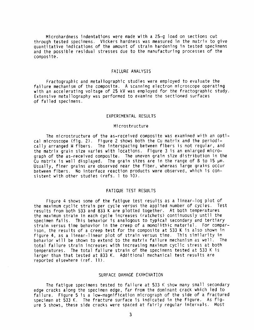
Microhardness indentations were made with a 25-g load on sections cutthrough tested specimens. Vickers hardness was measured in the matrix to givequantitative indications of the amount of strain hardening in tested specimensand the possible residual stresses due to the manufacturing processes of thecomposite.
FAILURE ANALYSIS
Fractographic and metallographlc studies were employed to evaluate the
failure mechanism of the composite. A scanning electron microscope operating
with an accelerating voltage of 25 kV was employed for the fractographic study.
Extensive metallography was performed to examine the sectioned surfaces
of failed specimens.
EXPERIMENTAL RESULTS
Microstructure
The microstructure of the as-received composite was examined with an opti-
cal microscope (fig. 2). Figure 2 shows both the Cu matrix and the periodi-
cally arranged W fibers. The interspacing between fibers is not regular, and
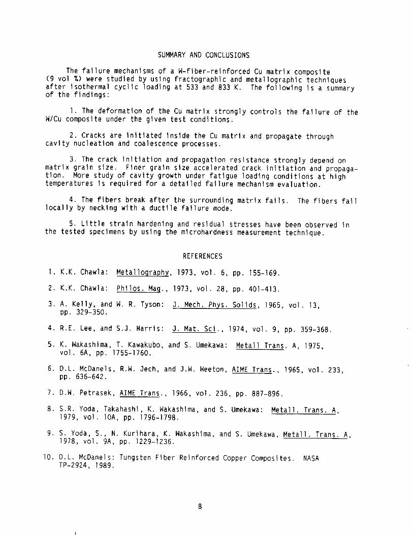
the matrix grain size varies with locations. Figure 3 is an enlarged micro-
graph of the as-received composite. The uneven grain size distribution in theCu matrix is well displayed. The grain sizes are in the range of 8 to 15 pm.
Usually, finer grains are observed near the fiber, whereas large grains occur
between fibers. No interface reaction products were observed, which is con-sistent with other studies (refs. l to lO).
FATIGUE TEST RESULTS
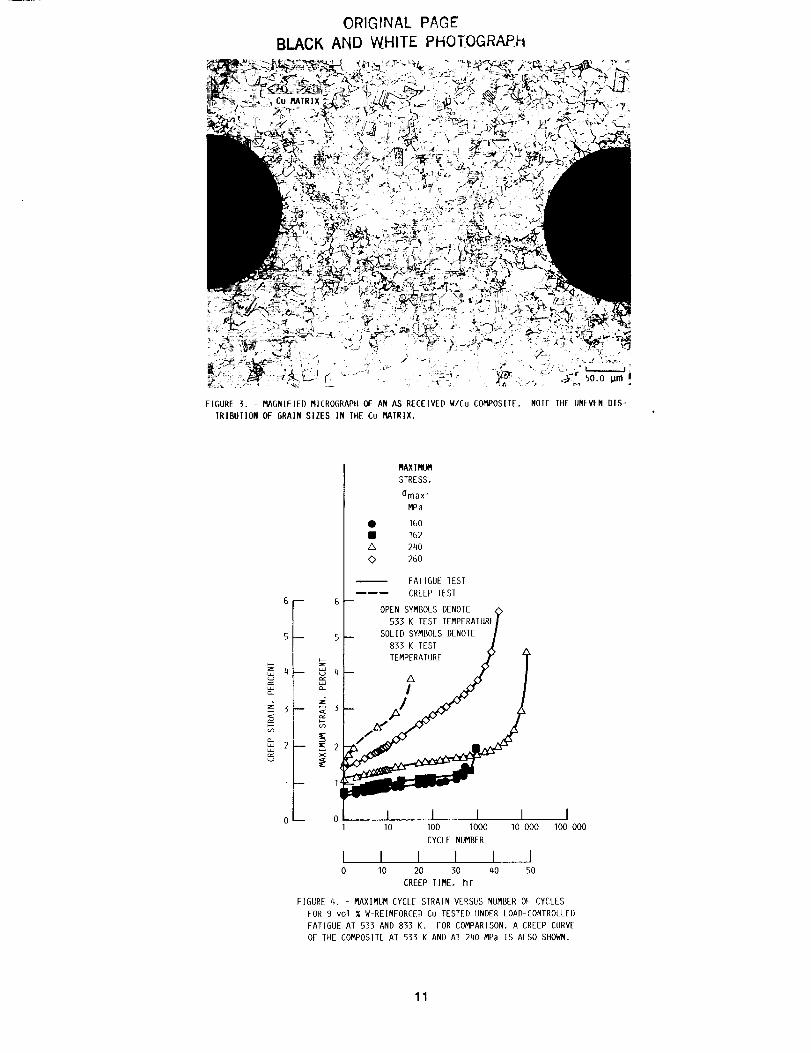
Figure 4 shows some of the fatigue test results as a linear-log plot ofthe maximum cyclic strain per cycle versus the applied number of cycles. Testresults from both 533 and 833 K are plotted together. At both temperaturesthe maximum strain in each cycle increases (ratchets) continuously untll thespecimen fails. This behavior is analogous to typical secondary and tertiarystrain versus time behavior in the creep of a monolithic materlal. For compar-ison, the results of a creep test for the composite at 533 K is also shown infigure 4, as a linear-linear plot of strain versus time. This similarity inbehavior will be shown to extend to the matrix failure mechanism as well. Thetotal failure strain increases with increasing maximum cyclic stress at bothtemperatures. The total failure strain of the specimens tested at 533 K islarger than that tested at 833 K. Additional mechanical test results arereported elsewhere (ref. II).
SURFACE DAMAGE EXAMINATION
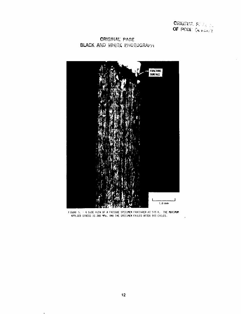
The fatigue specimens tested to failure at 533 K show many small secondary
edge cracks along the specimen edge, far from the dominant crack which led to
failure. Figure 5 is a low-magnification mlcrograph of the side of a fractured
specimen at 533 K. The fracture surface is indicated in the figure. As fig-ure 5 shows, these side cracks were spaced at fairly regular intervals. Most

of the side cracks only extended to the first row of fibers and then stoppedgrowing. In contrast, the specimens tested at 833 K did not develop as manysecondary-edge cracks nor did they exhibit as much accumulated plastic strain.
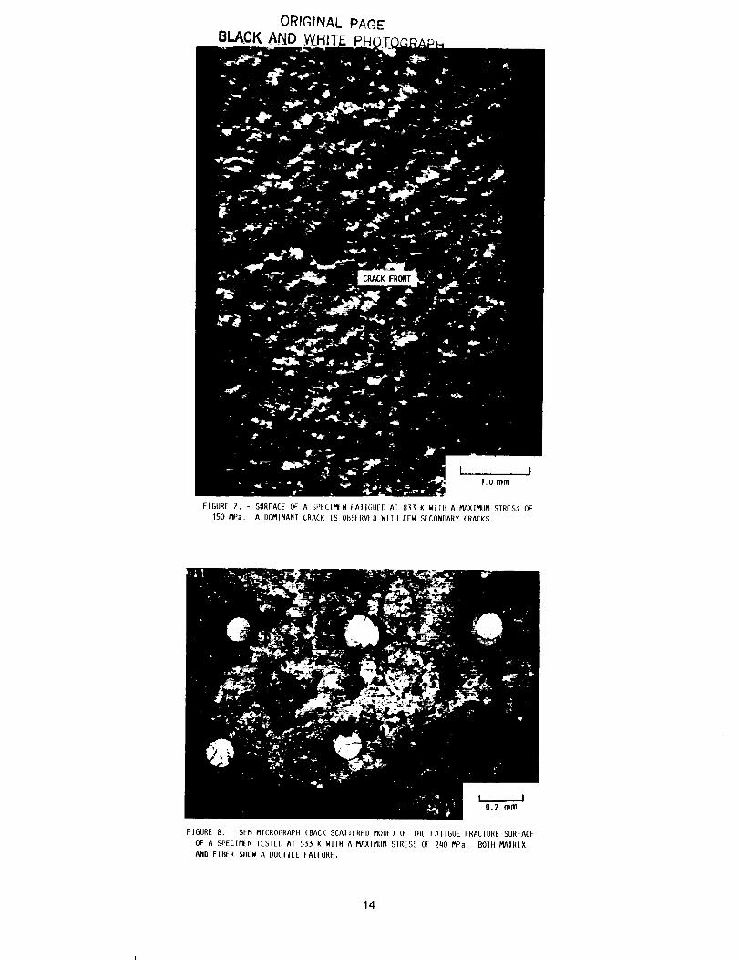
In addition to the secondary-edge cracks, numerous other small secondarycracks were observed near the fracture surface along the broad sides of thespecimen (fig. 6). These secondary cracks were again found mostly in specimenstested at 533 K and were not prevalent on specimens tested at 833 K. Some ofthese small secondary cracks were connected to the dominant crack and somewere not. Unlike the secondary-edge cracks, the location of these smaller sec-ondary cracks was confined near the fracture surface. The specimens tested at833 K did not show significant secondary cracks. Instead, one single majorcrack was found to propagate as shown in figure 7.
FRACTOGRAPHIC STUDY
The observed fracture surface shows that the dominant crack propagatedroughly transverse to the applied load, though microscopic observation revealsan irregular fatigue fracture morphology. It is very difficult to find a pathof crack propagation (e.g., river patterns) on the fracture surface. Fiberpullouts are rarely observed in the specimens tested at either temperature.Rather, the Cu matrix often adhered to the failed tungsten fibers.
Figure 8 shows the fracture surface of a fatigue specimen tested at 533 K.The composite experienced ductile failure in both constituents. The fiberfailure indicates large inelastic deformation that produced necking. Thematrix failed In fatigue by a predominantly intergranular mode, whereas finaltensile overload failure occurred by a predominantly transgranular mode.
Figure 9 is a magnified view of the failed matrix tested at 533 K. Fig-ure 9(a) is a fractograph of an intergranular fatigue failure region, andfigure 9(b) is a fractograph of a transgranular tensile failure region. Fig-ure 9(a) clearly shows the intergranular failure mode, along with a veryirregular grain size. No fatigue striation marks are observed, but the cracksand cavities along the grain boundaries are revealed. Figure 9 (b) reveals atypical ductile overload failure region. In these specimens, the intergranu-larly fractured regions are mostly confined to the outer surface of the speci-men and to the matrix surrounding the fiber. The ductile overload fracturenormally occurs in the middle of the specimen, in the midregion between fibers.
The fractography of specimens tested at 833 K is different from that at533 K. Most of the fracture surface exhibits an intergranular failure mode asshown in figure I0. Not much ductile overload failure is observed, even inthe middle of the specimen. The magnified view of the intergranularly frac-tured surface shows more clearly formed grain boundary cavities than those forthe 533 K tests.
To compare the fractography under different test conditions, we also exam-ined the fracture surface of a creep specimen ruptured under a static load of240 MPa at 533 K (fig. II). Compared with the fatigue specimen tested at thesame temperature, the matrix of the creep-ruptured specimen shows more predomi-nant intergranular failure throughout the specimen cross section. However thefracture nature of the tungsten fiber varies little from the fatigue specimen:the fiber exhibits large plastic deformation.

The SEMobservation of fractured surfaces also permitted the measurementof the reduction of area of tungsten fibers following cyclic failures. Thereduction of area of 30 to 40 fibers was measuredon each fracture surface.The measuredreduction of area of the fibers was approximately 70 percent forall of the tests performed at the two elevated temperatures. The room tempera-ture ductility of the fiber, however, is nil. The high reduction of area atthese relatively low elevated temperatures (0.14 to 0.27 Tm) seemsto be aninherent nature of the tungsten fiber, G.E. 218.
METALLOGRAPHICSTUDY
Figure 12 is an optical micrograph of a longitudinal section near thefracture surface of a specimen fatigue fractured at 533 K. The section showsone layer of fibers amongthe four plies which comprise the composite. Eventhough this section is not of the dominant crack, the secondary cracks shownin figure 12 can be assumedto be similar to those that occurred along the dom-inant fracture plane. The figure shows matrix cracks that are perpendicularto the loading direction and shows the fractured fibers. The cracks showninfigure 12 mayhave been widened during final failure of the specimen. Howeverthey still do provide information for crack initiation and propagation proc-esses. The large crack opening displacement at the left side of the specimenindicates that the dominant crack initiated at the side of the specimen andpropagated into the inner portion of the specimen.
Besides surface cracks, somecracks were observed to originate internallyin the Cu matrix. The crack marked "B" in the figure is one of such cracks.The crack is independent from the propagating approaching crack, marked "A",and apparently it initiated separately. Subsequentexaminations of underlyinglayers confirmed that these cracks were not connected.
The fibers are broken, forming nicely shaped necks at widely opened Cumatrix cracks, and fiber failure is not llmited to the crack front. The fibersseemto break after the surrounding matrix degrades. The deformation of thefiber appears to be very localized, since the necking is confined within avery narrow region between the mating surfaces of the propagating crack.
MICROHARDNESSTEST
In order to assess the amountof strain hardening and residual stressesin the Cu matrix, a microhardness test has been utilized. Several indentationswere made in the Cu matrix at equal intervals between fibers. A summary ofquantitative microhardness measurements on the matrix material is shown intable I. The hardness numbers in table I are averages of a minimum of sevenreadings. The average value was used since no significant variation of micro-hardness values (independent of location) could be detected within the matrix.The scatter of each of the hardness values in table I was approximately ±I0 Hv.
As the values indicate, the difference in hardness readings of the speci-mens tested under different conditions was also negligible. These smalldifferences suggest that the strain hardening in the Cu matrix due to fatiguetesting and possible residual stresses was not great enough to be detectedthrough this technique. These findings are consistent with Jones' work

(ref. 13). The softening of the matrix due to high-temperature annealing dur-ing fatigue tests was neglected for the present study, since vacuumannealingof the composite at the test temperatures without applied load did not showany significant softening of the Cu matrix.
DISCUSSION
The fatigued specimensat 533 and 833 K have shownsignificant differ-ences. The Cumatrix of specimens tested at 533 K had more secondary cracks,and the damageformation inside the Cu matrix (including cracks and cavities)at this temperature seemedto be a global phenomenon,not a localized one.The 833 K specimensshowedfew secondary cracks in the Cu matrix. Thesediff-erences at the two test temperatures seemto be associated with the differencein the failure strain (ductility) which the composite experienced during thecyclic loading. As noted in the former section, the specimens tested at 833 Khad a smaller cyclic failure strain. The decrease of the composite's failurestrain with increasing temperature is believed to be due to the failure modechangeof the Cu matrix.
It has been reported that Cu loses its ductility as temperature increasesbecauseof an enhancementof cavitation along grain boundaries (ref. 14). Theeffect of the N fiber on the composite failure behavior with temperaturechangesseemsto be small. The fatigue behavior of the N fibers at the twotemperatures were similar. Bartolotta et al. (P.A. Bartolotta, P.K. Brindley,and J.R. Ellis, ]989, NASATM, to be published.) investigated the relationshlpbetween the fiber failure modeand the total failure strain of a tungsten-fiber-reinforced superalloy composite (35 vol %), which is also a ductile-ductile system. They reported that the total failure strain does not changesignificantly with fiber failure characteristics whether the fiber failure isbrittle or ductile. The observations from these two references indicate theimportance of the matrix deformation in the composite failure during cyclicloading.
Figure ]3 is an SEMmicrograph of the Cu matrix near the fracture surface.The grain boundaries are severely damaged. Manycavities are revealed, andsomeof them are linked to form short cracks. This figure indicates that theintergranular failure was caused by cavity nucleation and coalescence processesalong grain boundaries. The meta]]ographic observations combinedwith thefractographs reveal that under the given test conditions cracks mostly initiateinside the Cu matrix at the outer surface of a specimen. They then propagatetowards the center of the specimen intergranularly by cavity growth and coales-cence processes.
The fiber-matrix interface was carefully examined and no cracks or debond-ing were observed. Comparedwith other metal matrix composites, the W/Cusys-tem exhibits no interfacial reaction products (refs. 1 to ]0) although theexact bond type is unknown. The specimens tested at 533 and 833 K also showthat the interface remained stable during testing, and no degradation phenom-ena or reaction products have been observed. Figure 14 showsa deformed fiberwith a neck. TheCu matrix still adheres to the deforming fiber, and the adja-cent matrix, - not the interface - is being cracked. In thermo-mechanica]fatigue tests, the interface maybe a weak, crack-initiation location. Theinterface maydegrade under such conditions. Yoda et al. (ref. 8) found that

pores form at the fiber/matrix interface during simple thermal cycling withthe same material. The failure mechanisms of the composite under such test
conditions are currently being investigated.
The fatigue failure of the composite strongly depends on the grain size
of the matrix. Figure 15 shows how the grain size affects the failure of the
composite. The small-grain region has more cavities than the large-grain
region, and cracks propagate more readily through the small-grain region.Currently, the authors believe that the grain size effect is related to grain
boundary sliding (GBS). Together with slip and diffusion, GBS is a well-
known deformation process in fine-grain materials. Luthy et al. (ref. 15)
modified the Ashby Deformation Map by including GBS as another deformation
mechanism. They showed that GBS plays an important role at all temperatures
in the deformation of a fine-grain material. Even though the composite speci-
men experienced only tension-tension cyclic loading, the Cu matrix is believed
to experience compressive stresses during the unloading cycle because of the
repeated plasticity and cyclic relaxation of the tensile matrix stresses.
Repeated tension and compression inside the Cu matrix results in cyclic shear
stresses that promote grain boundary sliding. It has also been reported that
a wedge-type cavitation prevails when grain boundary sliding is a major defor-mation mode (ref. 16). Some SEM pictures and optical micrographs from an
early stage of cavitation in an interrupted test specimen show more wedge-typecavltation than r-type cavitation. This observation again supports the view
that the composite matrix experiences grain boundary sliding under the given
loading conditions and temperatures. A specimen with a large-grain matrix
could have a prolonged life under the same loading conditions because of thedecreased chance of grain boundary sliding. Testing and analyses to further
confirm these findings are currently underway.
Another interesting observation related to the cavity nucleation and
growth is that, in many regions of the Cu matrix, very irregular cavity distri-
butions are found. Figure 16 shows a typical example of this irregular cavity
distribution. The composite has fewer cavities near the fiber/matrix inter-
face, and the cavities are frequently observed to be aligned with some degree
of regularity. Most of the time, the cavities are spread parallel to the load-
ing or fiber direction. This uneven distribution of cavities is believed tobe re]ated to the stress redistribution created by the fibers and the actual
mechanical loading.
The failure of the composite under the given test conditions can be sum-
marized as follows. Initially cracks were formed through plastic deformation
in the Cu matrix mostly at outer surfaces. Multiple cracks were initiated
depending on the amount of plastic deformation that the matrix experienced.
After a major crack was formed, the crack propagated by cavity growth and coa-
lescence processes. The breakage of fibers always came after the degradationof the surrounding matrix. The fibers were not cracked when the approaching
cracks reached the fiber. After the crack propagated past the fiber and the
surrounding matrix separated, the fiber deformed (with necking) and failed
locally in a ductile failure mode. The final failure of the composite occurred
when a sufficient area of a cross section of the specimen was cracked.
SUMMARYAND CONCLUSIONS
The failure mechanisms of a W-fiber-reinforced Cu matrix composite(9 vol %) were studied by using fractographic and metallographic techniquesafter isothermal cyclic loading at 533 and 833 K. The following is a summaryof the findings:
I. The deformation of the Cu matrix strongly controls the failure of theW/Cu composite under the given test conditions.
2. Cracks are initiated Inside the Cu matrix and propagate throughcavity nucleation and coalescence processes.
3. The crack initiation and propagation resistance strongly depend onmatrlx grain size. Finer grain size accelerated crack initiation and propaga-tion. More study of cavity growth under fatigue loading conditions at hightemperatures Is required for a detailed failure mechanism evaluation.
4. The fibers break after the surrounding matrix fails. The fibers falllocally by necking with a ductile failure mode.
5. Little strain hardening and resldual stresses have been observed inthe tested specimens by uslng the mlcrohardness measurement technique.
REFERENCES
I. K.K. Chawla: Metallography, 1973, vol. 6, pp. 155-169.
2. K.K. Chawla: Philos. Mag., 1973, vol. 28, pp. 401-413.
3. A. Kelly, and W. R. Tyson: J. Mech. Phys. Solids, 1965, vol. 13,pp. 329-350.
4. R.E. Lee, and S.J. Harrls: J. Mat. Sci., 1974, vol. 9, pp. 359-368.
5. K. Wakashima, T. Kawakubo, and S. Umekawa: Metal] Trans. A, 1975,vol. 6A, pp. 1755-1760.
6. D.L. McDanels, R.W. Jech, and J.W. Weeton, AIME Trans., 1965, vol. 233,pp. 636-642.
7. D.W. Petrasek, AIME Trans., 1966, vol. 236, pp. 887-896.
8. S.R. Yoda, Takahashi, K. Wakashima, and S. Umekawa: Metall. Trans. A,
1979, vol. lOA, pp. 1796-1798.
9. S. Yoda, S., N. Kurihara, K. Nakashima, and S. Umekawa, Metal]. Trans. A,1978, vol. 9A, pp. 1229-1236.
I0. D.L. McDanels: Tungsten Fiber Reinforced Copper Composites. NASATP-2924, 1989.

II. Verrilli, M., Yong-SukKim, and T.P. Gabb: High Temperature FatigueBehavior of Tungsten Copper Composite. Symposiumon FundamentalRelationships BetweenMicrostructure and Mechanical Properties ofMetal-Matrix Composites, Indiana, October I-5, 1989.
12. L.J. Westfa11" Tungsten Fiber Reinforced Superalloy Composite MonolayerFabrication by an ARC SPRAY Process. NASA TM-86917 (1985).
13. R.C. Jones" Metal Matrix Composites, pp.
Philadelphia, PA, 1968.
183-217, ASTM STP-438, ASTM,
14. Nleh, T.G. and W.D. Nix" Metall Trans. A, 1981, vol. 12A, 893-901.
15. H. Luthy, R.A. White, and O.D. Sherby" Mater Sci. Enq., 1979, vol. 39,pp. 211-216.
16. Balk, S., and R. Raj, Metall Trans. A, 1982, vol. 13A, pp. 1207-1214.
TABLE I. - MICROHARDNESS TEST RESULTS
OF THE CU MATRIX
Test condition
As receivedTensile fracture at 533 K
Fatigue fracture at 533 KTensile fracture at 833 K
Fatigue fracture at 833 K
Average Vickershardness,
Hv
7880878186

12.7
FIGURE 1. - SCHEMATIC DIAGRAM OF A RECTANGULAR SPECIMEN. ALL DI-
MENSIONS ARE GIVEN IN MILLIMETERS UNLESS MARKED OTHERWISE.
ORIGINAE PAGE
BLACK AND _HJTg P.HO!OGRAP__
Cu MATRIX
FIGURE 2. - AS-RECEIVED COMPOSITE SHOWING PERIODICALLY ARRANGED W FIBERS IN IHE Cu
MAIRIX.
lO
ORIGINAL PAGE
BLACK AND WHITE PHOTOGRAPJl
%
I: ; :_.-. % ": "'_Z_", , Y)_ ':_/'" so.o umJ
FIGURE 3. - RAGNIFIED MICROGRAPIIOF AN AS RECEIVED W/CU COt'lPOSIlE. NOTE TIlE UNEVENDIS-
TRIBUIION OF GRAIN SIZES IN THE Cu MATRIx.
6F---
5--
_ 4_
3_--
RAX1RUfl
STRESS,
Omax"
MPa
• 160
• _62/k 240
0 260
m FATIGUE IES]
_ CREEP TEST
-- OPEN SYMBOLS DENOTE
533 K TEST TEMPERATUREI
SOLID SYMBOLS DENOTE I5I
833 K TEST /
' J
I Io IO
I I I l II0 I00 I000 I0 000 I00 000
CYCLE NUMBER
I I I I20 30 40 50
CREEPTIME, hr
FIGURE 4. - MAXIMUM CYCLE STRAIN VERSUS NUMBER OF CYCtES
FOR 9 vol % W REINFORCED Cu TESTED UNDER IOAD CONTROLLED
FATIGUE AT 533 AND 833 K. FOR COMPARISON, A CREEP CURVE
OF THE COMPOSITE AT 533 K AND AT 240 MPa IS ALSO SHOWN.
11
C)RIGrNAE PAOE
BLACK A r_b Y_HJ]-E, _PYiO.[OGRA_rt
L ..J1,0 mm
FIGURE 5. - A SIDE VIEW OF A FATIGUE SPECIMEN fRACTURED AT 553 K. THE MAXIMUM
APPLIED SIRESS IS 280 MPa, AND THE SPECIMEN FAI{ED AFIER 9"33 CYCLES.
12

ORIGINAL PAGE
BLACK AND W,HJ,TE P_HO;EOGRAP_!t
1.0 mm
FIGUREARYCRACKS.G'- RROAOSII)EVIEW OF A FATIGUE SPECIMEN FRAC/ORED AT 533 K SHOWING NUMEROUS SECOND-
13
ORIGINAL PAGEK
1.0 mm
FIGURE 7. - SURFACE OF A SPFCIMEN (AII(]UII} A¿ R_ K WIIH A MAXIMUM STRESS OF
]50 MPa. A DOMINANT CRACK IS OBSERVED WITll FEW SECONDARY CRACKS.
FIGURE 8. - SEM MICROGRAPfl (BACK SCAIIERED MODE) OF lie FAIIGUE FRACIURE SURFACE
Of A SPECIMEN IESIED AT 5)_ K WITH A MAXIMUM SIRESS OF 2110 MPa. BOIII MAIRIX
AND FIBER SHOW A DUCIILE FAILURE.
14

ORIGINAE PAGE
BLACK AND WHITE PHOTOGRAP...H
(a) IN]ERGRANULAR fAILURE REGION.
2.opm
(b) 1RANSGRANULAR,DUCTILE OVERLOADFAILURE REGION.
FIGURE 9. - MAGNIFIED SEM FRACIOGRAPHSOF IIIE Cu MATRIX FAILED A1 533 K.
15

ORIGINAL PAGE
BLACK AND WHITE PHOTOGRAP_rl
FIGURE I0. - SEM MICROGRAPHS OF A FAIIGUE FRACIURE SURFACE FOR A SPECIMEN TESTED AT 833 K
SHOWING AN INCREASED ]NIERGRANULAR [ALLURE MODE IN IIIECu MAIRIX.
FIGURE 11. - SURFACE OF A CREEP-RUPTURE SPECIMEN IESIED UNDER ASIATIC LOAD
OF 2qO MPa AT 533 K IN VACUUM. A PREDOMINANt [NIERGRANULAR FAILURE MODE
IS OBSERVED IN IIIEMAIRIX.
16

ORIGINAl: PAGE
BLACK AND WHITE PHOTOGRAPH
]_ (-- __" LOADING DIRECIION
FIGURE 12. - IONGIIUDINAL SFCIION OF A FAIIGUE SPECIMEN
FRACTURED AT 533 K: MAXIMUM SIRESS, 260 MPa: MINIMUM
LOAD/MAXIMUM LOAD (R RATIO), 0.04. A, CRACK PROPAGAT-
ING FROM SPECIMEN SURf:ACE TO INIERIOR; B, INIERNALLY
ORIGINATING CRACK.
17

OPtGINAL PA(_'
BLACK AND.. _W_H_LTE£t40-I-OGRAPH
FIGURE 13. SEM MICROGRAPII Ol lIIE Cu MAIRIX OF A fATIGUE SPECIMEN FRACIURED
AT 5_3 K. MANY GRAIN BOUNDARY, CAVIIIIS AR_ RLV_ALLD, AND SOME OF TIIEM ARE
LINKED TO FORM MICROCRACKS.
F
Cu
50.0 pm
FIGURE I(I.- OPTICAL MICROGRAPIISIIOW]NGNECKIN(iOF A IUNGSIEN FIBER AFIER FATIGUE
AT 533 K.
18

ORIGrNAL PAGE'
BLACK A_D W_H]']'E PHO.LOGRAPtl
(a) CRACKS INITIATE AT FINE-GRAINED REGION.
}L____i
o. lo mm i
(b) CRACKS PROPAGATE THROUGIt FINE-GRAINED REGION.
FIGURE 15. - LONGIIUDINAL SECTION OF A SPECIMEN FATIGUE FRACTURED AT 533 K SHOW-
ING THE EFFECT OF GRAIN SIZE ON CRACK INITIATION AND PROPAGATION.
19

ORIGINAL PA_E
BLACK AJ_Q _H_II-II_ -PJ-IO.I_QGRAPh
10.0 pm i!
FIGURE 1G. - LONGITUDINAL SECTION Of A FATIGUE SPECIMEN FRACTUREDAT 533 K SHOW-ING UNEVEN DISTRIBUTION Of CAVITIES.
2O

Report Documentation PageNational Aeronaullcs andSpace Adm_r_str ation
1. Report No. 2. Government Accession No. 3. Recipient's Catalog No.
NASA TM- 102371
5. Report Date4. Title and Subtitle
Characterization of Failure Processes in Tungsten Copper Composites
Under Fatigue Loading Conditions
7. Author(s)
Yong-Suk Kim, Michael J. VerriIli, and Timothy P. Gabb
9. Performing Organization Name and Address
National Aeronautics and Space Administration
Lewis Research Center
Cleveland, Ohio 44135-3191
12. Sponsoring Agency Name and Address
National Aeronautics and Space Administration
Washington, D.C. 20546-0001
6. Performing Organization Code
8. Performing Organization Report No.
E-5090
10. Work Unit No.
553-13-00
11. Contract or Grant No.
13. Type of Report and Period Covered
Technical Memorandum
14. Sponsoring Agency Code
15. Supplementary Notes
Prepared for the International Symposium for Testing and Failure Analysis (ISTFA '89) sponsored by ASM
International, Los Angeles, California, November 6-10, 1989. Yong-Suk Kim, National Research Council--
NASA Research Associate.
16. Abstract
A fractographic and metallographic investigation was performed on specimens of a tungster_fiber-reinforced copper
matrix composite (9 vol%), which had experienced fatigue failures at elevated temperatures. The aim of the study
was to determine major failure modes and possible failure mechanisms, with an emphasis placed on characterizing
fatigue damage accumulation,. Metallography of specimens fatigued under isothermal cyclic loading suggested that
fatigue damage initiates in the matrix. Cracks nucleated within the copper matrix at grain boundaries, and they
propagated through cavity coalescence. The growing cracks subsequently interacted with the reinforcing tungsten
fibers, producing a localized ductile fiber failure. Examinations of interrupted tests before final failure confirmed
the suggested fatigue damage processes.
17. Key Words (Suggested by Author(s))
Fatigue (metal)
Metal matrix composite
Failure analysis
18. Distribution Statement
Unclassified- Unlimited
Subject Category 24
NASAFORM1626OCT66 "For sale by the National Technical Information Service, Springfield, Virginia 22161