CHARACTERIZATION METHODS: Chapter 3
13
2-1 nano 2000 CHARACTERIZATION METHODS: Chapter 3 we start with imaging methods: remember this?
Transcript of CHARACTERIZATION METHODS: Chapter 3

2-1
nano 2000
CHARACTERIZATION METHODS: Chapter 3
we start with imaging methods:
remember this?

2-2
1.3.1 Electron Microscopy
In 1931, Max Knoll and Ernst Ruska invented the transmission electron microscope (TEM), nearly 34 years after the discovery of the electron by J. J. Thomson. M. von Ardenna built the first commercial SEM in 1938, followed soon by the first commercially available TEM, built by Siemens in 1939. The principle of electron beam methods is simple. In order to observe objects with smaller dimensions, the wavelength of the probing source must also acquire comparably smaller dimensions. Erwin Müller, a professor in the Penn State University Physics Department, invented the field-ion EM. He is the first person known to see atoms. The first scientists however to fully exploit electron beam methods were biologists, an interesting irony. Since the resolution of the early scopes was not at the atomic level, it makes sense that relatively large biological structures were first in line to be described by TEM and SEM.
Ruska's original microscope from 1931
the first practical electron microscope had been built at the University of Toronto in 1938, by Eli Franklin Burton and students Cecil Hall, James Hillier, and Albert Prebus

2-3
we will meet several imaging methods in this course. let's see how they work.
Optics and Resolution: see page 116 et.seq.
1/f = 1/o + 1/i
o = distance to object
i = distance to image
Magnification (M) = i/o

2-4
in the electron microscope the magnification is determined by the size of the object on
screen divided by the size of the scanned area.
note: Magnification is how much bigger we can make something appear. Resolution is how much better we can distinguish two closely spaced points.
A lower limit on resolution is imposed by the fact that when we view specimens in a microscope, we are viewing them using waves. It is vitally important to understand that we cannot distinguish details finer than the wavelength of these waves. This is because light diffracts (bends into what 'should' be crisp shadows) and interferes with itself when moving around very small objects (or through very small holes).

2-5
Resolution:
Optical Microscopes: 0.35 micronswavelengths of visible light range from 400 to 700nm
Electron Microscopes: 0.2 nmwavelengths of electrons clearly much shorter!
Quality of microscope image is dependent on the Numerical Aperturethe numerical aperture (NA) of an optical system is a dimensionless
number that characterizes the range of angles over which the system can accept or emit light.
NA = n sin 2
n: refractive index2: half angle
R % 8/ NA
R is the resolving powerso: R gets better (smaller) as:
.wavelength gets shorter. 2. n (r.i. of connecting medium) gets bigger (oil better than air)
3. larger half angles and shorter focal length.

2-6

2-7
Three phenomena are relevant to resolution
1 Abbe Diffraction Barrier
2 Airy Disk
3 Rayleigh Criterion
1 Abbe Diffraction Barrier
Memorial to E.K. Abbe, who first approximated the diffraction limit
as
According to Abbe, a detail with a particular spacing in the specimen is resolved when the numerical aperture of the objective lens is large enough to
capture the first-order diffraction pattern produced by the detail at the wavelength employed.
In order to improve resolution at the diffraction limit
The NA must be increased
Related to the Airy disk :
2-8
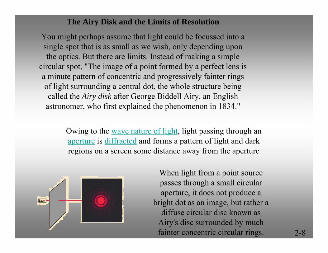
The Airy Disk and the Limits of Resolution
You might perhaps assume that light could be focussed into a single spot that is as small as we wish, only depending upon the optics. But there are limits. Instead of making a simple
circular spot, "The image of a point formed by a perfect lens isa minute pattern of concentric and progressively fainter rings of light surrounding a central dot, the whole structure being called the Airy disk after George Biddell Airy, an English
astronomer, who first explained the phenomenon in 1834."
Owing to the wave nature of light, light passing through an aperture is diffracted and forms a pattern of light and dark regions on a screen some distance away from the aperture
When light from a point source passes through a small circular aperture, it does not produce a
bright dot as an image, but rather a diffuse circular disc known as
Airy's disc surrounded by much fainter concentric circular rings.
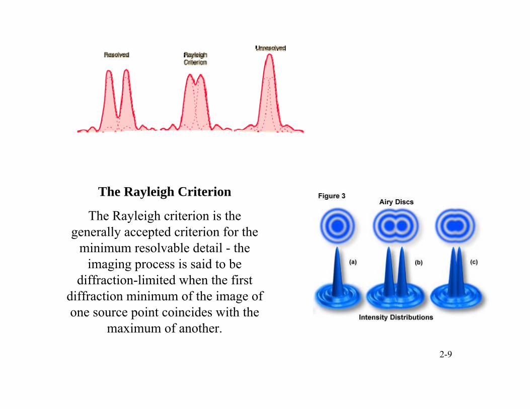
The Rayleigh Criterion
The Rayleigh criterion is the generally accepted criterion for the
minimum resolvable detail - the imaging process is said to be
diffraction-limited when the first diffraction minimum of the image of one source point coincides with the
maximum of another.
2-9

2-10
Electron probe methodsThese ideas will be useful to us. However in order to image at the nanoscale we must
use shorter wavelengths
Than visible light. Lets’ see how this is achieved using (first) electron probe methods.
The Wave Particle Duality
•1924: De Broglie hypothesized that allmatter possesses wave-like properties.
In quantum mechanics (& this course) this is most important when dealing with electrons.
mν ≡ momentum (measure of inertia or tendency of particle to remain in motion)
•Prince Louis-Victor Pierre Raymond de Broglie : Nobel Prize in Physics 1929
http://www.nobel.se/physics/laureates/1929/broglie-lecture.html
h/8 = h< = p
Converting p into the conventional mass-velocity form,
the wavelength of the electron is:
ph mν
h λ ==

2-11
Before we move on to look at how we can image (and do other things) with electrons a quick review of the
Wave – nature of electrons:
1927: Clinton, Davisson & Germer demonstrated (experimentally) that electrons are diffracted by crystals just like X-rays
It is interesting to recall that G.P. Thompson, who shared the 1937 Nobel Prize with Davisson for these experiments which proved that electrons are waves, is the son of J.J. Thompson who received the Nobel
Prize in 1906 for proving that cathode rays were actually particles - electrons! And the amazing
thing is that
they were both right

2-12
Electron Waves!
How??

2-13
A new kind of microscope reveals the structures of surfaces atom by atom. The instrument’s versatility may extend to investigators in the field of physics, chemistry and biology.
DNA We will meet this microscope very soon!