Characterization, electrical percolation and magnetization studies of polystyrene/multiwall carbon...
6
Materials Science and Engineering B 175 (2010) 189–194 Contents lists available at ScienceDirect Materials Science and Engineering B journal homepage: www.elsevier.com/locate/mseb Characterization, electrical percolation and magnetization studies of polystyrene/multiwall carbon nanotube composite films Ravi Bhatia ∗ , V. Prasad, Reghu Menon Department of Physics, Indian Institute of Science, Bangalore 560012, India article info Article history: Received 12 April 2010 Received in revised form 23 June 2010 Accepted 9 July 2010 Keywords: Composites Electron microscopy Electrical properties Magnetic properties abstract Polystyrene/multiwall carbon nanotube composite films are prepared with loading up to 7 weight percent (wt%) of multiwall carbon nanotubes by solution processing and casting technique. In the formation of these composite films, iron filled carbon nanotubes with high aspect ratio (∼4000) were used. Scanning electron microscopy study shows that the nanotubes are uniformly dispersed within the polymer matrix. At high magnification, bending of carbon nanotubes is noticed which can be attributed to their elastic properties. The electrical conductivity measurements show that the percolation threshold is rather low at 0.21 wt%. Hysteresis loop measurements on the bulk multiwall carbon nanotube and composite samples are done at 10, 150 and 300 K and the coercivity values are found to be largest at all the temperatures, for 1 wt% composite sample. © 2010 Elsevier B.V. All rights reserved. 1. Introduction Carbon nanotubes (CNTs) are thought to be one of the most promising reinforcing materials due to their extraordinary proper- ties. The inclusion of CNTs in polymer in small quantities improves the mechanical, electrical and thermal properties since the aspect ratio (ratio of length to diameter) of CNTs is very large, as well its density is rather low [1,2]. These polymer/CNT composites have a wide range of applications in field emission, electromagnetic shielding, gas sensing, actuation, etc. [3–6]. Different methods have been employed for the fabrication of polymer/CNT composites such as solvent route, melt mixing, ultrasound assisted twin screw extru- sion, etc. [7–9]. The most important issues for producing superior CNT composites are: (a) to achieve a high degree of dispersion of CNTs in polymer matrix and (b) strong interfacial interaction to enhance the bonding with polymer chains. Also the polymer com- posites prepared by using various kinds of solvent and polymers can exhibit wide range of structural and physical properties [8,10–13]. Usually the electrical properties of composites follow the perco- lation process, and the conductivity increases abruptly as the filler content approaches the percolation threshold (p c ), as the conduc- tive paths are established within the polymer matrix [14,15]. In fact percolation in these disordered systems depends on dispersion and aspect ratio of fillers; and in case of CNTs alignment of nan- otubes within the polymer and thickness of the composite sample are observed to play an important role [16,17]. Multiwall carbon nanotubes (MWCNTs) and carbon nanofibres (CNFs) are preferred ∗ Corresponding author. Tel.: +91 80 2293 2313, fax: +91 80 2360 2602. E-mail address: [email protected] (R. Bhatia). in the fabrication of composites due to their low cost and avail- ability [18,19]. Generally, MWCNTs are grown by chemical vapor deposition (CVD) using metal magnetic catalysts and these mag- netic catalytic particles remain trapped within the nanotubes [20]. Thus the metallic magnetic particles are prevented from oxidation as the carbon shell provides an effective barrier against oxidation while it is very difficult to prevent metallic nanoparticles from oxi- dation at conventional experimental conditions [21–23]. Moreover, nanoparticles trapped within the nanotubes are prevented from aggregation. Hence the use of CNTs filled with magnetic nanopar- ticles as filler in polymer may lead to composites with novel and applicative magnetic properties in addition to the electrical and mechanical properties. In this work, composite films of polystyrene (PS) and Fe filled MWCNTs are prepared by solution processing method. CVD grown MWCNTs containing trapped Fe nanoparticles were used as filler material which could lead to the incorporation of novel mag- netic properties to the non-magnetic matrix in addition to the enhancement in electrical conductivity. Room temperature electri- cal conductivity measurements of the composite films were done to estimate the percolation threshold. Magnetization vs. magnetic field measurements were done to evaluate the magnetic behavior of composite films. 2. Experimental 2.1. Fabrication of composite films MWCNTs used for the fabrication of the hybrid structure were synthesized by thermally assisted CVD of toluene and ferrocene mixture following a simple approach reported elsewhere [20]. The 0921-5107/$ – see front matter © 2010 Elsevier B.V. All rights reserved. doi:10.1016/j.mseb.2010.07.025
-
Upload
ravi-bhatia -
Category
Documents
-
view
219 -
download
0
Transcript of Characterization, electrical percolation and magnetization studies of polystyrene/multiwall carbon...
Cp
RD
a
ARRA
KCEEM
1
pttrdasbasCCepe
lctfaoan
0d
Materials Science and Engineering B 175 (2010) 189–194
Contents lists available at ScienceDirect
Materials Science and Engineering B
journa l homepage: www.e lsev ier .com/ locate /mseb
haracterization, electrical percolation and magnetization studies ofolystyrene/multiwall carbon nanotube composite films
avi Bhatia ∗, V. Prasad, Reghu Menonepartment of Physics, Indian Institute of Science, Bangalore 560012, India
r t i c l e i n f o
rticle history:eceived 12 April 2010eceived in revised form 23 June 2010
a b s t r a c t
Polystyrene/multiwall carbon nanotube composite films are prepared with loading up to 7 weight percent(wt%) of multiwall carbon nanotubes by solution processing and casting technique. In the formation of
ccepted 9 July 2010
eywords:ompositeslectron microscopy
these composite films, iron filled carbon nanotubes with high aspect ratio (∼4000) were used. Scanningelectron microscopy study shows that the nanotubes are uniformly dispersed within the polymer matrix.At high magnification, bending of carbon nanotubes is noticed which can be attributed to their elasticproperties. The electrical conductivity measurements show that the percolation threshold is rather low at0.21 wt%. Hysteresis loop measurements on the bulk multiwall carbon nanotube and composite samples
00 Kle.
lectrical propertiesagnetic properties
are done at 10, 150 and 3for 1 wt% composite samp
. Introduction
Carbon nanotubes (CNTs) are thought to be one of the mostromising reinforcing materials due to their extraordinary proper-ies. The inclusion of CNTs in polymer in small quantities improveshe mechanical, electrical and thermal properties since the aspectatio (ratio of length to diameter) of CNTs is very large, as well itsensity is rather low [1,2]. These polymer/CNT composites havewide range of applications in field emission, electromagnetic
hielding, gas sensing, actuation, etc. [3–6]. Different methods haveeen employed for the fabrication of polymer/CNT composites suchs solvent route, melt mixing, ultrasound assisted twin screw extru-ion, etc. [7–9]. The most important issues for producing superiorNT composites are: (a) to achieve a high degree of dispersion ofNTs in polymer matrix and (b) strong interfacial interaction tonhance the bonding with polymer chains. Also the polymer com-osites prepared by using various kinds of solvent and polymers canxhibit wide range of structural and physical properties [8,10–13].
Usually the electrical properties of composites follow the perco-ation process, and the conductivity increases abruptly as the fillerontent approaches the percolation threshold (pc), as the conduc-ive paths are established within the polymer matrix [14,15]. Inact percolation in these disordered systems depends on dispersion
nd aspect ratio of fillers; and in case of CNTs alignment of nan-tubes within the polymer and thickness of the composite samplere observed to play an important role [16,17]. Multiwall carbonanotubes (MWCNTs) and carbon nanofibres (CNFs) are preferred∗ Corresponding author. Tel.: +91 80 2293 2313, fax: +91 80 2360 2602.E-mail address: [email protected] (R. Bhatia).
921-5107/$ – see front matter © 2010 Elsevier B.V. All rights reserved.oi:10.1016/j.mseb.2010.07.025
and the coercivity values are found to be largest at all the temperatures,
© 2010 Elsevier B.V. All rights reserved.
in the fabrication of composites due to their low cost and avail-ability [18,19]. Generally, MWCNTs are grown by chemical vapordeposition (CVD) using metal magnetic catalysts and these mag-netic catalytic particles remain trapped within the nanotubes [20].Thus the metallic magnetic particles are prevented from oxidationas the carbon shell provides an effective barrier against oxidationwhile it is very difficult to prevent metallic nanoparticles from oxi-dation at conventional experimental conditions [21–23]. Moreover,nanoparticles trapped within the nanotubes are prevented fromaggregation. Hence the use of CNTs filled with magnetic nanopar-ticles as filler in polymer may lead to composites with novel andapplicative magnetic properties in addition to the electrical andmechanical properties.
In this work, composite films of polystyrene (PS) and Fe filledMWCNTs are prepared by solution processing method. CVD grownMWCNTs containing trapped Fe nanoparticles were used as fillermaterial which could lead to the incorporation of novel mag-netic properties to the non-magnetic matrix in addition to theenhancement in electrical conductivity. Room temperature electri-cal conductivity measurements of the composite films were doneto estimate the percolation threshold. Magnetization vs. magneticfield measurements were done to evaluate the magnetic behaviorof composite films.
2. Experimental
2.1. Fabrication of composite films
MWCNTs used for the fabrication of the hybrid structure weresynthesized by thermally assisted CVD of toluene and ferrocenemixture following a simple approach reported elsewhere [20]. The

1 and Engineering B 175 (2010) 189–194
aaSp
p
wAu(oawcf
2
epo(tsDl
t∼moKitS
3
i2awneFarmbMtoisoet
chnmm
90 R. Bhatia et al. / Materials Science
s-prepared MWCNTs were quite aligned and its aspect ratio isbout 4000. PS (molecular wt. ∼230,000) was purchased fromigma–Aldrich. Different weight percent (wt%) samples were pre-ared according to Eq. (1):
= Mc
Mc + Mp× 100 (1)
here Mc and Mp are the masses of MWCNT and PS, respectively.specific amount of MWCNTs was dispersed in toluene (5 ml) by
ltrasonication for several minutes; and PS was dissolved in toluene100 mg/5 ml) in a separate beaker. The well dispersed suspensionf MWCNTs was then mixed with the PS solution. This mixture of PSnd MWCNTs was again sonicated for 20 min until the MWCNTs areell dispersed. This PS/MWCNT mixture was dried in an oven to get
omposite films. Composite films with different wt% of MWCNTs,rom 0.1 to 7 wt%, were prepared by this simple approach.
.2. Characterization
The FEI Quanta 200 scanning electron microscope (SEM),quipped with a tungsten electron source, was used for mor-hological studies of PS/MWCNT composite films. For the SEMbservations, the composite samples were coated with a thin layer∼5 nm) of Au to avoid heating or charging effects. Technai F30ransmission electron microscope (TEM) was used for the detailedtructural study of MWCNTs filled with Fe nanoparticles. BRUKER8 Advance X-ray diffractometer (XRD) [Cu K� X-rays with wave-
ength 1.54 A] was used to obtain XRD pattern.A standard linear four probe method was used to measure
he conductivity of the composite films (sample dimensions3 mm × 8 mm, thickness ∼70 �m). The electrical contacts wereade by conducting silver paste. A constant current in the range
f 0.1–10 �A was applied to the outer leads of the samples usingiethley 220 programmable current source, and the voltage in the
nner two probes was measured through Kiethley 2000 multime-er. Magnetization measurements were done in a Quantum DesignQUID magnetometer (MPMS XL).
. Results and discussion
Fig. 1(a) shows the SEM micrograph of MWCNTs. The approx-mate outer diameter and length of MWCNTs are 50–80 nm and00–300 �m, respectively. SEM micrograph shows that the tubesre closely bundled up with less amount of amorphous carbon. Asell a very uniform diameter distribution of MWCNTs can also beoticed. TEM study of as-prepared MWCNTs confirms the pres-nce of catalytic Fe nanoparticles at various lengths of nanotubes.ig. 1(b) displays the TEM micrograph of Fe filled MWCNTs. Theverage diameter and length of Fe nanoparticles are 20 and 100 nm,espectively. These MWCNTs were used for the preparation of poly-er composite films. The high quality of MWCNTs was confirmed
y Raman spectroscopy. Fig. 1(c) shows the Raman spectrum ofWCNTs. The graphitic peak (G peak) appears at 1572.7 cm−1 and
he defect peak (D peak) at 1342.5 cm−1. The ratio of the intensitiesf G to D is a measure of the structural perfection of MWCNTs. Heret can be easily observed in the shown Raman spectrum of MWCNTample that the G peak intensity is very high in comparison to thatf D peak intensity, with G/D peak ratio ∼4, which is quite large. Thisnsures that both high aspect ratio and fewer amounts of defects inhese MWCNTs are expected to give high quality composite films.
Fig. 2 presents the low magnification SEM micrographs of
omposite films. These micrographs confirm the high degree ofomogeneous dispersion of filler in the PS matrix. The homoge-eous distribution of filler material into the polymer matrix is veryuch required for enhancing the physical properties, as alreadyentioned, which is nontrivial in case of polymer/CNT compositeFig. 1. (a) SEM micrograph of MWCNTs; (b) TEM micrograph of Fe filled MWCNTs.Inset: HRTEM micrograph of an MWCNT embedded with Fe nanoparticle (c) Ramanspectrum of MWCNTs. The ratio of the intensities of G peak to D peak is ∼4.
films. It is known that the electrical conductivity of a polymer/CNTcomposite sample is adversely affected by the agglomeration ofCNTs. A homogeneous distribution of the conducting fillers enablesto form well connected conducting network so that optimal prop-erties of both fillers and polymer host can be obtained in thecomposite film. Therefore, in order to facilitate the homogeneousdistribution of CNTs throughout the polymer matrix, surfactantslike sodium dodecyl sulphate, sodium dodecylbenzene sulfonate,
etc. have been used to improve the dispersion of CNTs [24,25].Also the use of special solvents like N-methyl-2-pyrrolidone canimprove the dispersability of CNTs [26]. Ramasubermaniam et al.[27] achieved low percolation threshold due to homogeneous dis-
R. Bhatia et al. / Materials Science and Engineering B 175 (2010) 189–194 191
Fig. 2. Low magnification SEM micrographs of PS/MWCNT composites of (a) 1 wt%, (b) 3 wt%, (c) 5 wt%, and (d) 7 wt% of MWCNTs.
Fig. 3. High magnification SEM micrographs of PS/MWCNT composites of (a) 1 wt%, (b) 3 wt%, (c) 5 wt%, and (d) 7 wt% of MWCNTs.
1 and Engineering B 175 (2010) 189–194
pacatasbtobtmm
iIuBPpobToSfiaspatpi
TT
92 R. Bhatia et al. / Materials Science
ersion by non-covalent functionalization of CNTs. Shi et al. [28]lso reported an enhanced dispersion and interfacial bonding ofarbon nanofibres within the polymer matrix by plasma coatingpproach. However, we have achieved a homogeneous distribu-ion without using any surfactants. The possible reason for suchgood dispersion of MWCNTs within the PS is probably the adhe-
ion and interaction between MWCNTs and PS interface, which maye attributed to the toluene present in the solution. While sonica-ion some of the toluene molecules get adsorbed onto the surfacef the MWCNTs via non-covalent interactions (�–� stacking)etween MWCNT surface and toluene molecules. This facilitateshe adhesion and interaction between MWCNTs and long polymer
olecules and hence MWCNTs get embedded into the polymeratrix.The higher magnification SEM micrographs are shown in Fig. 3,
n which the nanoscale distribution of MWCNTs can be observed.nterestingly, the middle part of the MWCNT is slightly bentpwards and both ends are dipped into the soft polymer matrix.ending effect of MWCNT may be understood as follows. When theS and MWCNT solution is about to dry to cast the polymer com-osite film, the polymer gets shrunk and thus the effective lengthf MWCNT is decreased. Due to the elastic properties of MWCNTs,ending effect occurs which is being observed in all the samples.his kind of bending effect of MWCNT within polymer had beenbserved previously by Lourie et al. [29] and Bower et al. [30].tudies on this bent structured MWCNT embedded in a polymericlm have suggested that the compressive strengths of nanotubesre about two orders of magnitude higher than the compressivetrength of any known fibre [29]. XRD patterns of PS/MWCNT com-
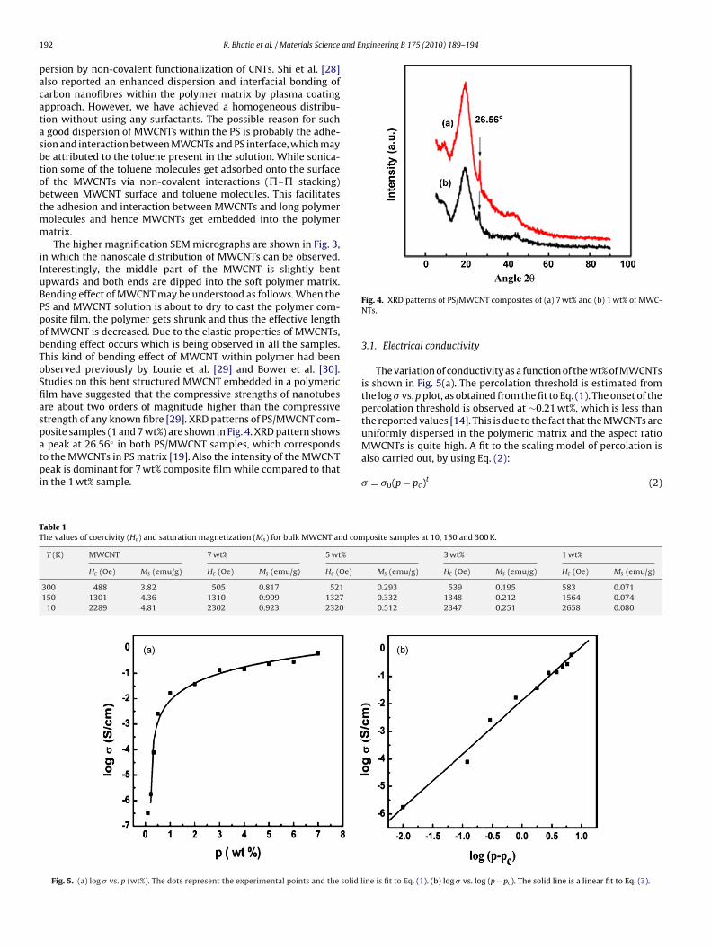
osite samples (1 and 7 wt%) are shown in Fig. 4. XRD pattern showspeak at 26.56◦ in both PS/MWCNT samples, which correspondso the MWCNTs in PS matrix [19]. Also the intensity of the MWCNTeak is dominant for 7 wt% composite film while compared to that
n the 1 wt% sample.
able 1he values of coercivity (Hc) and saturation magnetization (Ms) for bulk MWCNT and com
T (K) MWCNT 7 wt% 5 wt%
Hc (Oe) Ms (emu/g) Hc (Oe) Ms (emu/g) Hc (Oe)
300 488 3.82 505 0.817 521150 1301 4.36 1310 0.909 1327
10 2289 4.81 2302 0.923 2320
Fig. 5. (a) log � vs. p (wt%). The dots represent the experimental points and the solid l
Fig. 4. XRD patterns of PS/MWCNT composites of (a) 7 wt% and (b) 1 wt% of MWC-NTs.
3.1. Electrical conductivity
The variation of conductivity as a function of the wt% of MWCNTsis shown in Fig. 5(a). The percolation threshold is estimated fromthe log � vs. p plot, as obtained from the fit to Eq. (1). The onset of thepercolation threshold is observed at ∼0.21 wt%, which is less thanthe reported values [14]. This is due to the fact that the MWCNTs areuniformly dispersed in the polymeric matrix and the aspect ratio
MWCNTs is quite high. A fit to the scaling model of percolation isalso carried out, by using Eq. (2):� = �0(p − pc)t (2)
posite samples at 10, 150 and 300 K.
3 wt% 1 wt%
Ms (emu/g) Hc (Oe) Ms (emu/g) Hc (Oe) Ms (emu/g)
0.293 539 0.195 583 0.0710.332 1348 0.212 1564 0.0740.512 2347 0.251 2658 0.080
ine is fit to Eq. (1). (b) log � vs. log (p − pc). The solid line is a linear fit to Eq. (3).
and E
l
w�it
Fa
R. Bhatia et al. / Materials Science
og � = log �0 + t log(p − pc) (3)
here � is the actual conductivity of the composite sample,0 is the characteristic conductivity of the composite film, ‘p’
s the wt% of MWCNTs in the composite film, pc is percolationhreshold and ‘t’ is the critical exponent. The values of ‘t’ and
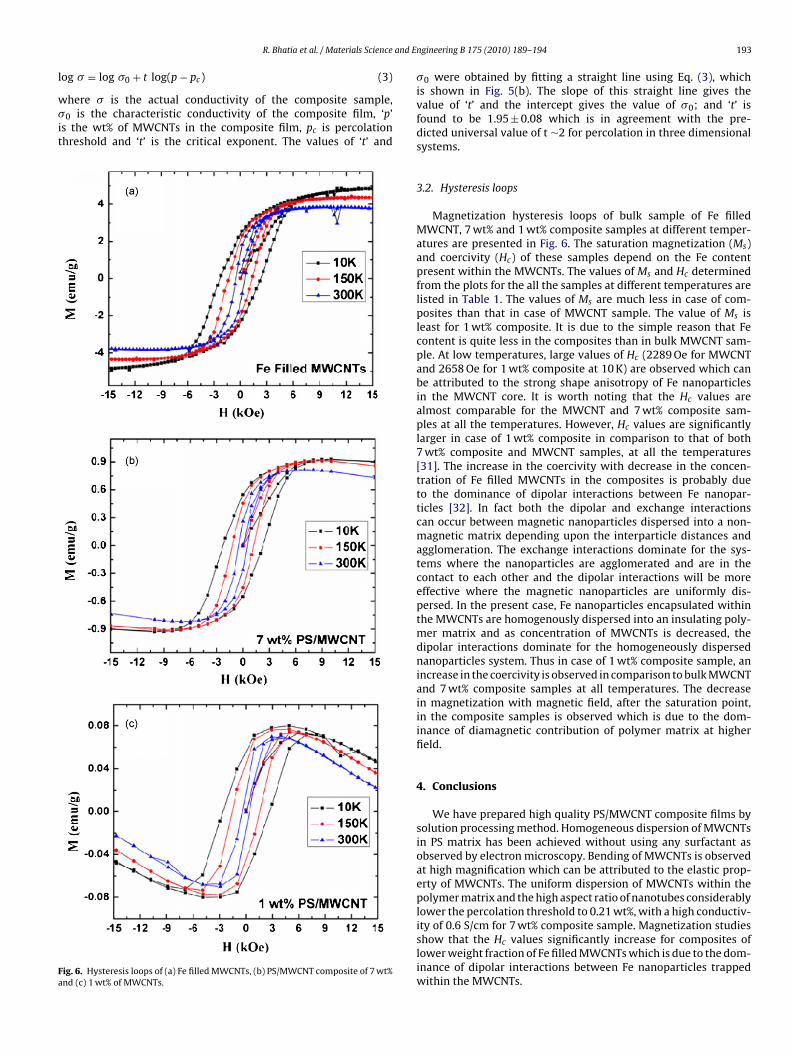
ig. 6. Hysteresis loops of (a) Fe filled MWCNTs, (b) PS/MWCNT composite of 7 wt%nd (c) 1 wt% of MWCNTs.
ngineering B 175 (2010) 189–194 193
�0 were obtained by fitting a straight line using Eq. (3), whichis shown in Fig. 5(b). The slope of this straight line gives thevalue of ‘t’ and the intercept gives the value of �0; and ‘t’ isfound to be 1.95 ± 0.08 which is in agreement with the pre-dicted universal value of t ∼2 for percolation in three dimensionalsystems.
3.2. Hysteresis loops
Magnetization hysteresis loops of bulk sample of Fe filledMWCNT, 7 wt% and 1 wt% composite samples at different temper-atures are presented in Fig. 6. The saturation magnetization (Ms)and coercivity (Hc) of these samples depend on the Fe contentpresent within the MWCNTs. The values of Ms and Hc determinedfrom the plots for the all the samples at different temperatures arelisted in Table 1. The values of Ms are much less in case of com-posites than that in case of MWCNT sample. The value of Ms isleast for 1 wt% composite. It is due to the simple reason that Fecontent is quite less in the composites than in bulk MWCNT sam-ple. At low temperatures, large values of Hc (2289 Oe for MWCNTand 2658 Oe for 1 wt% composite at 10 K) are observed which canbe attributed to the strong shape anisotropy of Fe nanoparticlesin the MWCNT core. It is worth noting that the Hc values arealmost comparable for the MWCNT and 7 wt% composite sam-ples at all the temperatures. However, Hc values are significantlylarger in case of 1 wt% composite in comparison to that of both7 wt% composite and MWCNT samples, at all the temperatures[31]. The increase in the coercivity with decrease in the concen-tration of Fe filled MWCNTs in the composites is probably dueto the dominance of dipolar interactions between Fe nanopar-ticles [32]. In fact both the dipolar and exchange interactionscan occur between magnetic nanoparticles dispersed into a non-magnetic matrix depending upon the interparticle distances andagglomeration. The exchange interactions dominate for the sys-tems where the nanoparticles are agglomerated and are in thecontact to each other and the dipolar interactions will be moreeffective where the magnetic nanoparticles are uniformly dis-persed. In the present case, Fe nanoparticles encapsulated withinthe MWCNTs are homogenously dispersed into an insulating poly-mer matrix and as concentration of MWCNTs is decreased, thedipolar interactions dominate for the homogeneously dispersednanoparticles system. Thus in case of 1 wt% composite sample, anincrease in the coercivity is observed in comparison to bulk MWCNTand 7 wt% composite samples at all temperatures. The decreasein magnetization with magnetic field, after the saturation point,in the composite samples is observed which is due to the dom-inance of diamagnetic contribution of polymer matrix at higherfield.
4. Conclusions
We have prepared high quality PS/MWCNT composite films bysolution processing method. Homogeneous dispersion of MWCNTsin PS matrix has been achieved without using any surfactant asobserved by electron microscopy. Bending of MWCNTs is observedat high magnification which can be attributed to the elastic prop-erty of MWCNTs. The uniform dispersion of MWCNTs within thepolymer matrix and the high aspect ratio of nanotubes considerablylower the percolation threshold to 0.21 wt%, with a high conductiv-
ity of 0.6 S/cm for 7 wt% composite sample. Magnetization studiesshow that the Hc values significantly increase for composites oflower weight fraction of Fe filled MWCNTs which is due to the dom-inance of dipolar interactions between Fe nanoparticles trappedwithin the MWCNTs.
1 and E
A
tcaD
R
[
[
[
[
[
[
[[
[[
[[
[
[[
[[
[[
94 R. Bhatia et al. / Materials Science
cknowledgments
We gratefully acknowledge the Institute of Nanoscience Initia-ive, Indian Institute of Science, Bangalore for the SEM and TEMharacterization. We are thankful to I. Sameera for the supportnd useful discussions. R. Bhatia wishes to acknowledge UGC, Newelhi for providing the contingent grant.
eferences
[1] E.T. Thostenson, Z. Ren, T.W. Chou, Compos. Sci. Technol. 61 (2001) 1899.[2] M. Moniruzzaman, K.I. Winey, Macromolecules 39 (2006) 5194.[3] R.C. Smith, J.D. Carey, R.J. Murphy, W.J. Blau, J.N. Coleman, S.R.P. Silva, Appl.
Phys. Lett. 87 (2005) 263105.[4] Y. Yang, M.C. Gupta, K.L. Dudley, R.W. Lawrence, Nanoletters 5 (2005) 2131.[5] J.K. Abraham, B. Philip, A. Witchurch, V.K. Varadan, C.C. Reddy, Smart Mater.
Struct. 13 (2004) 1045.[6] H. Koerner, G. Price, N.A. Pearce, M. Alexender, R.A. Vaia, Nat. Mater. 3 (2004)
115.[7] J. Liu, T. Liu, S. Kumar, Polymer 46 (2005) 3419.[8] Q. Zhang, S. Rastogi, D. Chen, D. Lippits, P.J. Lemskra, Carbon 44 (2006) 778.[9] A.I. Isayev, R. Kumar, T.M. Lewis, Polymer 50 (2009) 250.
10] Z. Guo, K. Lei, Y. Li, H.W. Ng, S. Prikhodko, H.T. Hahn, Compos. Sci. Technol. 68(2008) 1513.11] Z. Guo, S. Park, S. Wei, T. Pereira, M. Moldovan, A.B. Karki, D.P. Young, H.T. Hahn,
Nanotechnology 18 (2007) 335704.12] B. Suo, X. Su, J. Wu, D. Chen, A. Wang, Z. Guo, Mater. Chem. Phys. 119 (2010)
237.
[[[
[
ngineering B 175 (2010) 189–194
13] P. Mavinakuli, S. Wei, Q. Wang, A.B. Karki, S. Dhage, Z. Wang, D.P. Young, Z. Guo,J. Phys. Chem. C 114 (2010) 3874.
14] H.M. Kim, M.S. Choi, J. Joo, S.J. Cho, H.S. Yoon, Phys. Rev. B 74 (2006)054202.
15] R. Bhatia, C.S.S. Sangeeth, V. Prasad, R. Menon, Appl. Phys. Lett. 96 (2010)242113.
16] F. Du, J.E. Fischer, K.I. Winey, Phys. Rev. B(R) 72 (2005) 121404.17] M. Fu, Y. Yu, J.J. Xie, L.P. Wang, M.Y. Fan, S.L. Jiang, Y.K. Zeng, Appl. Phys. Lett.
94 (2009) 012904.18] J. Zhu, S. Wei, A. Yadav, Z. Guo, Polymer 51 (2010) 2643.19] J. Zhu, S. Wei, J. Ryu, M. Budhathoki, G. Liang, Z. Guo, J. Mater. Chem. 20 (2010)
4937.20] R. Bhatia, V. Prasad, Solid State Commun. 150 (2010) 311.21] D. Zhang, S. Wei, C. Kaila, X. Su, J. Wu, A.B. Karki, D.P. Young, Z. Guo, Nanoscale
2 (2010) 917.22] D. Zhang, R. Chung, A.B. Karki, F. Li, D.P. Young, Z. Guo, J. Phys. Chem. C 114
(2010) 212.23] Z. Guo, L.L. Henry, E.J. Podlahaa, ECS Trans. 1 (2006) 63.24] B. Vigolo, A. Penicaud, C. Coulon, C. Sauder, R. Pailler, C. Journet, et al., Science
290 (2000) 1331.25] J.I. Paredes, M. Burghard, Langmuir 20 (2004) 5149.26] F.M. Blighe, Y.R. Hernandez, W.J. Blau, J.N. Coleman, Adv. Mater. 19 (2007)
4443.27] R. Ramasubermaniam, J. Chen, H. Liu, Appl. Phys. Lett. 83 (2003) 2928.28] D. Shi, J. Lian, P. He, F. Xiao, L. Yang, M.J. Schulz, D.B. Mast, Appl. Phys. Lett. 83
(2003) 5301.29] O. Lourie, D.M. Cox, H.D. Wagner, Phys. Rev. Lett. 81 (1998) 1638.30] C. Bower, R. Rosen, L. Jinb, J. Han, O. Zhou, Appl. Phys. Lett. 74 (1999) 3317.31] Z. Guo, S. Park, H.T. Hahn, S. Wei, M. Moldovan, A.B. Karki, D.P. Young, Appl.
Phys. Lett. 90 (2007) 053111.32] A. Ceylan, C.C. Baker, S.K. Husanain, S.I. Shah, Phys. Rev. B 72 (2005) 134411.