Characterization and Modeling of Sheared Edge Failure in ...
69
Characterization and Modeling of Sheared Edge Failure in Advanced High Strength Steel by Nikky Pathak A thesis presented to the University of Waterloo in fulfilment of the thesis requirement for the degree of Doctor of Philosophy in Mechanical and Mechatronics Engineering Waterloo, Ontario, Canada, 2018 © Nikky Pathak 2018
Transcript of Characterization and Modeling of Sheared Edge Failure in ...
Characterization and Modeling of Sheared Edge Failure
in Advanced High Strength Steel
by
Nikky Pathak
A thesis
presented to the University of Waterloo
in fulfilment of the
thesis requirement for the degree of
Doctor of Philosophy
in
Mechanical and Mechatronics Engineering
Waterloo, Ontario, Canada, 2018
© Nikky Pathak 2018
ii
Examining Committee Membership
The following served on the Examining Committee for this thesis. The decision of the
Examining Committee is by majority vote.
External Examiner:
Chester Van Tyne
Professor, Colorado School of Mines
Supervisors:
Michael Worswick
Professor, University of Waterloo
Cliff Butcher
Assistant Professor, University of Waterloo
Internal Member:
Kaan Inal
Associate Professor, University of Waterloo
Mary Wells
Professor, University of Waterloo
Internal-External Member:
Rob Gracie
Associate Professor, University of Waterloo

iii
AUTHOR’S DECLARATION
This thesis consists of material all of which I authored or co-authored: see Statement of
Contributions included in the thesis. This is a true copy of the thesis, including any required final
revisions, as accepted by my examiners.
I understand that my thesis may be made electronically available to the public.
iv
STATEMENT OF CONTRIBUTIONS
The following co-authors have contributed to the current work:
Professor Michael Worswick and Professor Cliff Butcher supervised this Ph.D. thesis.
Professor Cliff Butcher contributed significantly in implementation of the UMAT
Dr. Erika Bellhouse assisted with preparing metallographic specimen.
Dr. Jeff Gao provided materials and access to the metallographic laboratory.
Dr. Jerome Adrien assisted in performing the tomography experiments and Professor Eric Maire
supervised the tomography experiments.
Armin Abedini helped in yield function calibration
The balance of the research is my own work.
v
ABSTRACT
Edge failure is one of the major problems associated with forming of advanced high strength
steels (AHSS) such as dual-phase (DP) steels. The development of ferritic-bainitic steels such as
complex-phase (CP) steels have improved the performance of AHSS in industrial forming
operations and is gaining attention in academia as well as industry. As a result, there is an
interest in developing numerical techniques to predict sheared edge failure in forming
simulations and optimize forming operations in the automotive industry for vehicle
lightweighing. The primary objective of this thesis is to examine the influence of shearing on
edge stretchability and damage evolution in two different grades of AHSS: CP and DP steels and
develop damage-based models to predict sheared edge failure.
The stretch-flangeability of DP and CP steels were evaluated using a hole expansion test for
different edge conditions to isolate to the influence of a range of factors thought to influence
edge formability. The results demonstrate that work hardening and void damage at the sheared
edge govern formability while the sheared surface quality plays a minor or secondary role. A
comparison of the edge stretching limits of DP and CP steels demonstrates the advantages of a
ferritic-bainitic microstructure for forming operations with severe local deformation as in a
stretch-flanging operation.
The failure mechanisms in the CP and DP steels were systematically characterized by
interrupting hole tension tests at different strain levels. Scanning electron microscope (SEM)
analysis conducted on interrupted hole tension specimens revealed the ductile failure mechanism
as being operative in the CP and DP steels for the different edge conditions and microstructures.
Damage histories were developed from the interrupted samples using optical microscopy and
quantitative stereology measurement of void nucleation, growth and coalescence, paired with in
situ digital image correlation (DIC) strain measurements during the mechanical testing. The
trend of damage evolution differs for the sheared edge in contrast with the reamed edge because
the shearing process alters the microstructure in the shear affected zone (SAZ) by introducing
work-hardening and damage behind the sheared edge.
Two independent experimental techniques were applied to characterize the residual strain
distribution within the shear-affected zone for CP800 and DP780 steels based on (a) the tendency
of grains to orient in the direction of shearing and (b) work-hardening introduced within the
vi
deformed shear zone. The first technique was developed by applying finite strain theory to
calculate the equivalent strain from microstructural measurements of grain rotation. The second
strain measurement technique also involved using the same interrupted shear tests and DIC
strains followed by microhardness measurements to develop a correlation between the equivalent
strain and hardness. These techniques were applied to estimate the strain-distribution behind the
sheared edge generated during the shearing process.
The influence of stress-state on micro-void nucleation was evaluated experimentally for the
CP and DP steels and a stress-state dependent nucleation model was developed. Stress state was
varied by considering four specimen geometries: the equi-biaxial Nakazima test, a plane strain
v-bend test, a central hole tension test for uniaxial loading and a simple shear test. 3D micro-
tomography and quantitative stereology measurement of void nucleation paired with in situ
digital image correlation (DIC) strain measurement was conducted on the interrupted samples to
quantify damage as a function of equivalent strain. The influence of stress-state on damage
evolution was observed for both materials with very little void nucleation under shear
deformation but extensive void damage under biaxial tension. Of particular interest, Lode
parameter-dependency of void nucleation was identified and a stress-state dependent nucleation
model is proposed by introducing a nucleation strain surface as a function of stress-triaxiality and
Lode parameter using a modified form of Chu and Needleman nucleation criterion.
The critical damage parameters controlling the ductile failure process were identified from
the void histories determined using 3D tomography to develop a micromechanics-based fracture
model. An uncoupled anisotropic damage-based fracture model was formulated within an LS-
DYNA user-defined material subroutine. The pre-strain and damage introduced during the
shearing process were mapped onto finite element models of edge formability. The proposed
model was validated for the hole tension experiments and found to predict failure efficiently and
accurately for the CP800 and DP780 alloys with a reamed or sheared edge conditions.
vii
Acknowledgements
I would like to express my gratitude to my supervisor Prof. Michael Worswick, who apart
from being a great researcher and mentor, is also one of the most considerate persons I have
come across. I would like to thank him for his strong support, patience, guidance throughout and
also for providing me freedom to conduct my research.
I would also like to thank my co-supervisor Prof. Cliff Butcher, without whom this research
could not have been accomplished. His experience and knowledge of fracture characterization
and micromechanics-based models were fundamental in shaping this work. I would like to
express my gratitude for his encouragement and constant availability for technical discussions.
I would like to thank Prof. Eric Maire from INSA, Lyon for providing me the opportunity to
conduct tomography experiments and his guidance. Support from this research from
ArcelorMittal Dofasco and AUTO21 is gratefully acknowledged, especially Erika Bellhouse,
Rex Holden and Sam Pao for willingness to help in any way possible.
The experimental work in the lab would not be possible without the assistance from the
MME staff and I am grateful to Eckhard Budziarek, Andy Barber, Jeff Wemp and Tom Gawel
for their support in the lab and laughter outside. I would like to thank Rick Forgett, Karl Janzen
and Charlie Boyle from Engineering Machine shop for coming up with innovative ideas to
machine my unconventional tomography samples. I want to thank Laurie Wilfong for her
administrative support and Jose Imbert and Alexander Bardelcik for helping me throughout my
academic life in Waterloo.
I would like to express my heartfelt thanks to grad friends through all these years: Kaab and
Sam for movie nights, Armin and Luke for valuable discussions, Ekta for amazing food,
Taamjeed for introducing high-rate shear and Sante for entertainment. Shout-outs to Amir, Cale,
Cameron, Jacqueline, Pedram, Rohit, Ryan, Srihari and Yonathan. I would also like to thank the
staff at Tim Horton’s for making the many thousands of cups of coffee that kept me going in past
5 years.
I will always remember endless laughter with Meenu, Deepak, Jalaj and Shitikanth during
UNO nights. I had a great time with my apartment-mate Meenu and her interesting philosophical
outlook and cooking made staying with her even more enjoyable. I would like to thank Jalaj and

viii
Shitikanth for introducing me to Squash and Deepak for his political entertainment. I would
always relish party nights at Westcourt place with my friends: Sandeep, Shivam, Deepak,
Shitikanth, Pampa, Shilpa. A great thanks to KD and Nithya for making my stay at Waterloo
wonderful, a detailed poker lesson and developing my taste-buds.
I can’t thank my parents enough who sacrificed so much to give my sister (Neha) and I a
better life. My parents have been a pillar of strength and it is their untiring support and
encouragement that gave me the determination and will to pursue my endeavors. I would like to
thank Neha didi and Rohit jiju for their constant support, love, care and pampering. Special
thanks to Vihaan, the newest addition in family, for his giggles and laughter. I am so grateful to
my new family: parent-in law, Sonam didi, Raja bhaiya and Saina for their unending support.
Lastly, my husband, Nitish, for putting up with the seemingly never-ending thesis and related
crankiness. I am fortunate to have him and his unyielding love, support and patience.

ix
Dedication
To my family
x
Table of Contents
Examining Committee Membership ............................................................................................... ii
AUTHOR’S DECLARATION ...................................................................................................... iii
STATEMENT OF CONTRIBUTIONS ........................................................................................ iv
ABSTRACT .................................................................................................................................... v
Acknowledgements ....................................................................................................................... vii
Dedication ...................................................................................................................................... ix
List of Figures ............................................................................................................................... xii
List of Tables ................................................................................................................................ xv
1. Introduction ............................................................................................................................. 1
2. Literature Review .................................................................................................................... 2
2.1. Sheared process and characteristics of the sheared edge ................................................. 2
2.2. Sheared Edge Stretching-limit ......................................................................................... 3
2.3. Fracture mechanism in AHSS .......................................................................................... 4
2.3.1. Void nucleation ......................................................................................................... 5
2.3.2. Void growth and coalescence ................................................................................... 6
2.4. Numerical Modeling of Ductile Failure ........................................................................... 8
2.4.1. Modeling of void nucleation ..................................................................................... 8
2.4.2. Modeling void growth............................................................................................... 8
2.4.3. Modeling void coalescence ....................................................................................... 9
2.4.4. Alternative approaches to modelling ductile failure ............................................... 10
2.5. Finite element simulation of the hole expansion test ..................................................... 11
2.6. Current state of knowledge in the sheared edge stretching ............................................ 12
3. Objective ................................................................................................................................ 14
4. Summary of the Research Results ......................................................................................... 15
4.1. Assessment of the Critical Parameters Influencing the Edge Stretchability of Advanced
High Strength Steel Sheet ......................................................................................................... 16
4.1.1. Influence of the Punch Geometry ........................................................................... 16
4.1.2. Influence of the Edge Condition ............................................................................. 17
4.2. Damage Evolution in Complex-Phase and Dual-Phase Steels during Edge Stretching 19
4.2.1. Damage Development Resulting from Shearing and Hole Tensile Deformation... 20
4.2.2. Quantitative Examination of Damage Progression ................................................. 23
xi
4.3. Experimental Techniques for Residual Shear Strain Measurement with Applications to
Sheared Edge Stretching of Advanced High Strength Steel ..................................................... 25
4.3.1. Correlating Shear Angle and Hardness Measurement with Shear Strain using Shear
Test 25
4.3.2. Characterization of the Sheared Edge ..................................................................... 28
4.4. Experimental Stress State-Dependent Void Nucleation Behaviour for Two 800 MPa
Advanced High Strength Steels................................................................................................. 30
4.4.1. Damage Evolution under Proportional Loading ..................................................... 31
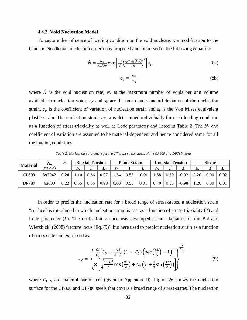
4.4.2. Void Nucleation Model ............................................................................................... 32
4.5. Micro-Mechanics based Fracture Model to Predict Edge Failure in 800 MPa Advanced
High Strength Steels .................................................................................................................. 34
4.5.1. Damage Evolution during the Edge Stretching ...................................................... 34
4.5.2. Constitutive Model.................................................................................................. 35
5. Discussion .............................................................................................................................. 39
6. Conclusions ........................................................................................................................... 41
7. Future Work ........................................................................................................................... 43
References ..................................................................................................................................... 44
APPENDIX A: Part 1 ................................................................................................................... 50
APPENDIX B: Part 2.................................................................................................................... 51
APPENDIX C: Part 3.................................................................................................................... 52
APPENDIX D: Part 4 ................................................................................................................... 53
APPENDIX E: Part 5 .................................................................................................................... 54
xii
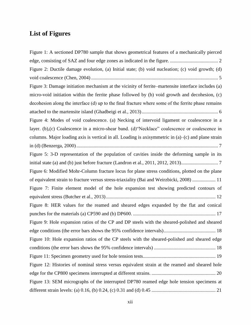
List of Figures
Figure 1: A sectioned DP780 sample that shows geometrical features of a mechanically pierced
edge, consisting of SAZ and four edge zones as indicated in the figure. ....................................... 2
Figure 2: Ductile damage evolution, (a) Initial state; (b) void nucleation; (c) void growth; (d)
void coalescence (Chen, 2004) ....................................................................................................... 5
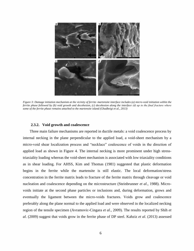
Figure 3: Damage initiation mechanism at the vicinity of ferrite–martensite interface includes (a)
micro-void initiation within the ferrite phase followed by (b) void growth and decohesion, (c)
decohesion along the interface (d) up to the final fracture where some of the ferrite phase remains
attached to the martensite island (Ghadbeigi et al., 2013) .............................................................. 6
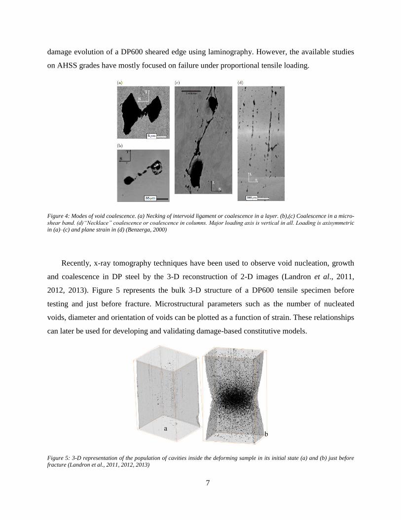
Figure 4: Modes of void coalescence. (a) Necking of intervoid ligament or coalescence in a
layer. (b),(c) Coalescence in a micro-shear band. (d)“Necklace” coalescence or coalescence in
columns. Major loading axis is vertical in all. Loading is axisymmetric in (a)–(c) and plane strain
in (d) (Benzerga, 2000) ................................................................................................................... 7
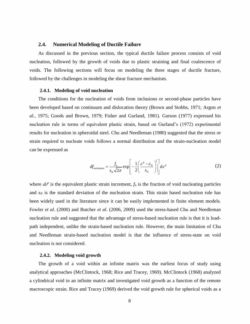
Figure 5: 3-D representation of the population of cavities inside the deforming sample in its
initial state (a) and (b) just before fracture (Landron et al., 2011, 2012, 2013) .............................. 7
Figure 6: Modified Mohr-Column fracture locus for plane stress conditions, plotted on the plane
of equivalent strain to fracture versus stress-triaxiality (Bai and Weirzbicki, 2008) ................... 11
Figure 7: Finite element model of the hole expansion test showing predicted contours of
equivalent stress (Butcher et al., 2013) ......................................................................................... 12
Figure 8: HER values for the reamed and sheared edges expanded by the flat and conical
punches for the materials (a) CP590 and (b) DP600. ................................................................... 17
Figure 9: Hole expansion ratios of the CP and DP steels with the sheared-polished and sheared
edge conditions (the error bars shows the 95% confidence intervals) .......................................... 18
Figure 10: Hole expansion ratios of the CP steels with the sheared-polished and sheared edge
conditions (the error bars shows the 95% confidence intervals) .................................................. 18
Figure 11: Specimen geometry used for hole tension tests........................................................... 19
Figure 12: Histories of nominal stress versus equivalent strain at the reamed and sheared hole
edge for the CP800 specimens interrupted at different strains. .................................................... 20
Figure 13: SEM micrographs of the interrupted DP780 reamed edge hole tension specimens at
different strain levels: (a) 0.16, (b) 0.24, (c) 0.31 and (d) 0.45 .................................................... 21
xiii
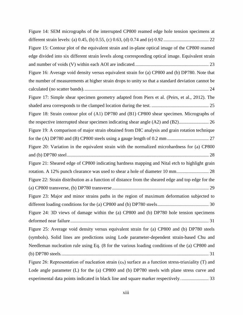
Figure 14: SEM micrographs of the interrupted CP800 reamed edge hole tension specimens at
different strain levels: (a) 0.45, (b) 0.55, (c) 0.63, (d) 0.74 and (e) 0.92 ...................................... 22
Figure 15: Contour plot of the equivalent strain and in-plane optical image of the CP800 reamed
edge divided into six different strain levels along corresponding optical image. Equivalent strain
and number of voids (V) within each AOI are indicated. ............................................................. 23
Figure 16: Average void density versus equivalent strain for (a) CP800 and (b) DP780. Note that
the number of measurements at higher strain drops to unity so that a standard deviation cannot be
calculated (no scatter bands). ........................................................................................................ 24
Figure 17: Simple shear specimen geometry adapted from Piers et al. (Peirs, et al., 2012). The
shaded area corresponds to the clamped location during the test. ................................................ 25
Figure 18: Strain contour plot of (A1) DP780 and (B1) CP800 shear specimen. Micrographs of
the respective interrupted shear specimen indicating shear angle (A2) and (B2) ......................... 26
Figure 19: A comparison of major strain obtained from DIC analysis and grain rotation technique
for the (A) DP780 and (B) CP800 steels using a gauge length of 0.2 mm ................................... 27
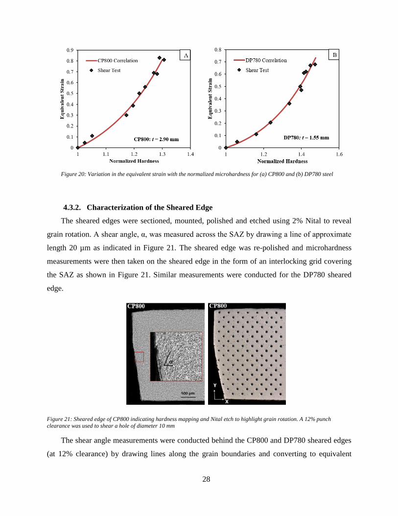
Figure 20: Variation in the equivalent strain with the normalized microhardness for (a) CP800
and (b) DP780 steel ....................................................................................................................... 28
Figure 21: Sheared edge of CP800 indicating hardness mapping and Nital etch to highlight grain
rotation. A 12% punch clearance was used to shear a hole of diameter 10 mm ........................... 28
Figure 22: Strain distribution as a function of distance from the sheared edge and top edge for the
(a) CP800 transverse, (b) DP780 transverse ................................................................................. 29
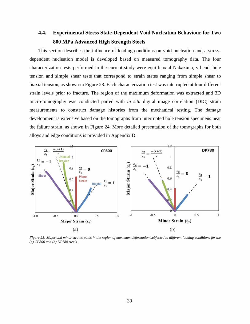
Figure 23: Major and minor strains paths in the region of maximum deformation subjected to
different loading conditions for the (a) CP800 and (b) DP780 steels ........................................... 30
Figure 24: 3D views of damage within the (a) CP800 and (b) DP780 hole tension specimens
deformed near failure .................................................................................................................... 31
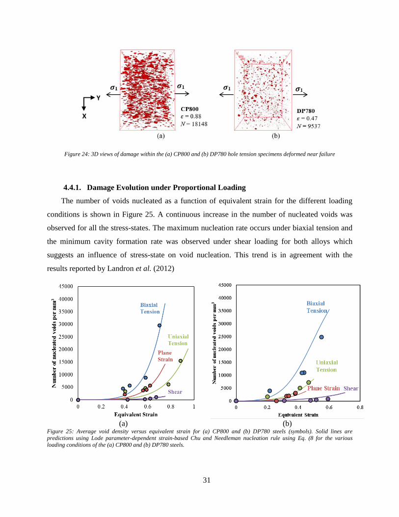
Figure 25: Average void density versus equivalent strain for (a) CP800 and (b) DP780 steels
(symbols). Solid lines are predictions using Lode parameter-dependent strain-based Chu and
Needleman nucleation rule using Eq. (8 for the various loading conditions of the (a) CP800 and
(b) DP780 steels. ........................................................................................................................... 31
Figure 26: Representation of nucleation strain (εN) surface as a function stress-triaxiality (T) and
Lode angle parameter (L) for the (a) CP800 and (b) DP780 steels with plane stress curve and
experimental data points indicated in black line and square marker respectively. ....................... 33
xiv
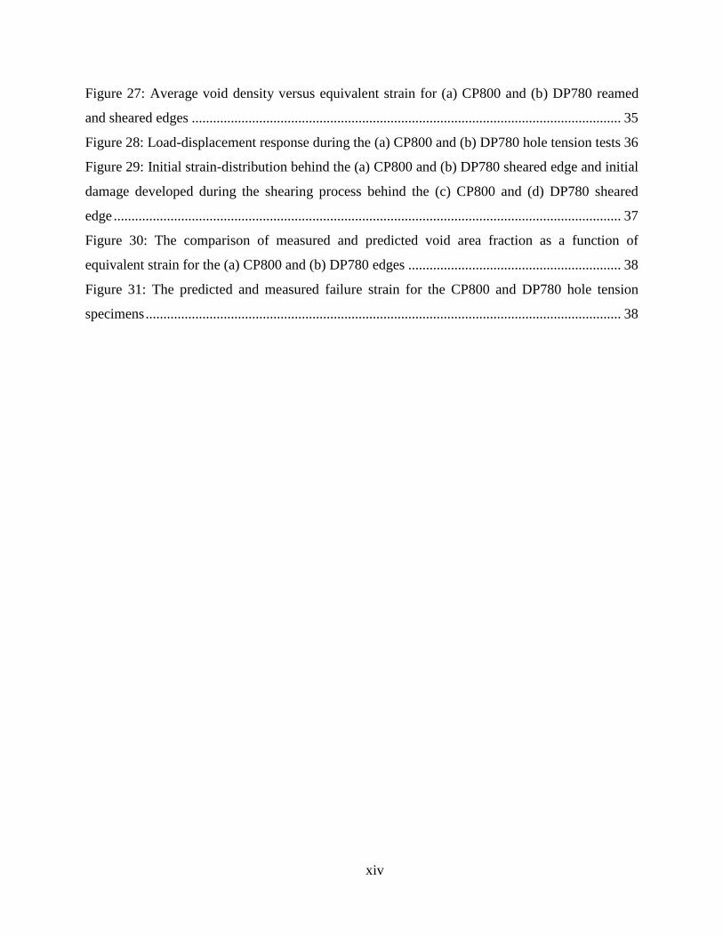
Figure 27: Average void density versus equivalent strain for (a) CP800 and (b) DP780 reamed
and sheared edges ......................................................................................................................... 35
Figure 28: Load-displacement response during the (a) CP800 and (b) DP780 hole tension tests 36
Figure 29: Initial strain-distribution behind the (a) CP800 and (b) DP780 sheared edge and initial
damage developed during the shearing process behind the (c) CP800 and (d) DP780 sheared
edge ............................................................................................................................................... 37
Figure 30: The comparison of measured and predicted void area fraction as a function of
equivalent strain for the (a) CP800 and (b) DP780 edges ............................................................ 38
Figure 31: The predicted and measured failure strain for the CP800 and DP780 hole tension
specimens ...................................................................................................................................... 38

xv
List of Tables
Table 1: Inverse power law parameters (a and b) for the CP800 and DP780 steels ..................... 27
Table 2: Nucleation parameters for the different stress-states of the CP800 and DP780 steels ... 32
1
1. Introduction
Shearing of a material prior to forming is very common in the automotive industry and this
process alters the material at the edge through severe non-uniform deformation. Consequently, a
significant portion of the formability of a material is consumed by the shearing process and can
result in a premature failure during a subsequent forming operation. Producing a machined edge
in industrial parts will improve edge formability but at the expense of production cost and time.
This problem becomes more severe with multi-phase AHSS such as ferritic-martensitic dual-
phase (DP) steels due to the severe stress-gradients created between the ferrite and martensite
phases (Avramovic-Cingara et al., 2009). For steel manufacturers, increasing demand for AHSS
in industrial stretch-flanging operations has provided an incentive to manipulate the
microstructures of AHSS grades that has led to the development of ferritic-bainitic alloys such as
complex-phase (CP) steels (Pathak et al., 2017a). A better understanding of the factors governing
failure during sheared edge stretching is necessary to further improve the performance of AHSS
steels and predict edge failure in industrial forming operations. Thus, the motivation of the
current work is to experimentally characterize the factors controlling the formability of a sheared
edge in AHSS and to develop an accurate constitutive model for the simulation of sheared edge
stretching operations. Detailed damage characterization measurements, assessing void
nucleation, growth and coalescence, were conducted to identify critical parameters controlling
fracture in CP and DP steels and the manner in which edge shearing alters the damage processes
during edge stretching. A unified framework for a micromechanics-based fracture model is
proposed. The main beneficiaries of this work will be those who are interested in the accurate
and efficient simulation of sheared edge failure in practical forming simulations of automotive
components. The accurate prediction of sheared edge failure is also necessary for those who are
seeking to optimize shearing processes.
This thesis has been written in a “manuscript-based” style that includes first this synopsis of
the thesis work, followed by several parts documenting each aspect of the research. The synopsis
comprises a concise review of the current state of the art in sheared edge stretching, an outline of
the objectives of this thesis research and a summary of the research results, followed by
discussion, conclusions and future work. The remainder of the thesis consists of five individual
manuscripts that detail the work done and results accomplished to fulfill the objectives.
2
2. Literature Review
2.1. Sheared process and characteristics of the sheared edge
In the shearing process, a punch is used to push the work-piece against the die, which is
fixed and separates the sheet metal into two pieces at the edge of the shearing punch and die. The
clearance is the gap between the die and punch and is typically expressed as a percentage of the
sheet thickness. The shearing process introduces two zones; a shear face (sheared edge) and a
zone of deformation behind the shear face known as the shear-affected zone (SAZ) (Levy and
Van Tyne, 2012).
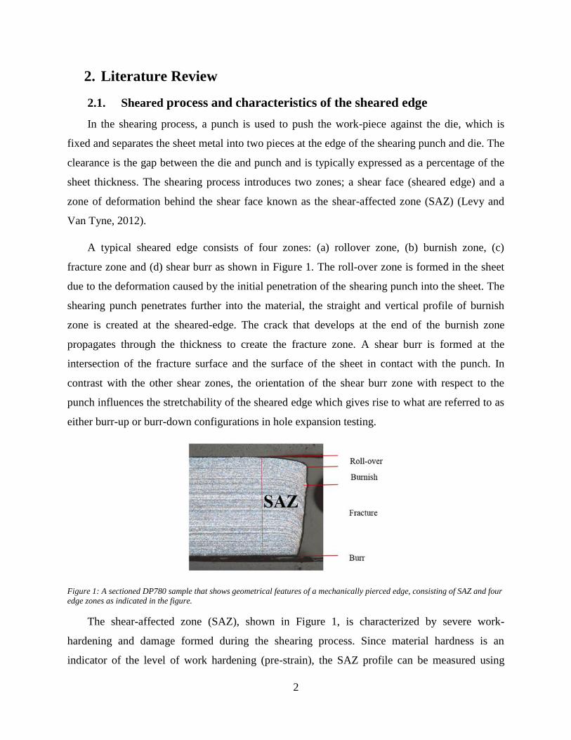
A typical sheared edge consists of four zones: (a) rollover zone, (b) burnish zone, (c)
fracture zone and (d) shear burr as shown in Figure 1. The roll-over zone is formed in the sheet
due to the deformation caused by the initial penetration of the shearing punch into the sheet. The
shearing punch penetrates further into the material, the straight and vertical profile of burnish
zone is created at the sheared-edge. The crack that develops at the end of the burnish zone
propagates through the thickness to create the fracture zone. A shear burr is formed at the
intersection of the fracture surface and the surface of the sheet in contact with the punch. In
contrast with the other shear zones, the orientation of the shear burr zone with respect to the
punch influences the stretchability of the sheared edge which gives rise to what are referred to as
either burr-up or burr-down configurations in hole expansion testing.
Figure 1: A sectioned DP780 sample that shows geometrical features of a mechanically pierced edge, consisting of SAZ and four
edge zones as indicated in the figure.
The shear-affected zone (SAZ), shown in Figure 1, is characterized by severe work-
hardening and damage formed during the shearing process. Since material hardness is an
indicator of the level of work hardening (pre-strain), the SAZ profile can be measured using
3
micro-hardness tests. When the hardness at the edge saturates to a baseline value, the end of SAZ
is detected (Wu et al., 2012; Konieczny and Henderson, 2007; Davies, 1983). The deformation
pattern in the SAZ includes a large shear-induced rotation of the grains that increases with
proximity to the sheared edge. Wu et al. (2012) sectioned the sheared edge in the through-
thickness direction and measured the angle of rotation by highlighting the material flow lines.
The flow line tilting angles measured on the sheared edge were then used to compute the strain
due to work-hardening in the SAZ using finite-strain theory, as explained by Wu et al. (2012).
2.2. Sheared Edge Stretching-limit
Hole expansion tests are commonly used to evaluate the formability of a material in stretch
flanging operations. The test consists of expanding a hole with a punch until a through-thickness
crack appears. The hole expansion ratio (HER) is the formability metric and is expressed as the
ratio of the change in diameter to the original hole diameter as defined by the following equation:
(1)
where do is the initial hole diameter and df is the inside hole diameter at fracture. The ISO
16630:2009 (ISO-16630, 2009) standard for the hole expansion test recommends using a conical
punch with a 60o included angle to expand the hole. The dependency of the HER on various
process parameters such as punch geometry, clearance of the shear dies and edge condition have
been well documented in the literature. Konieczny and Henderson (2007) considered different
punch geometries: flat, conical and hemispherical and the largest final hole diameter was
achieved using a conical punch while the minimum resulted from using a cylindrical punch. An
alternate test to predict failure for the sheared edge stretching is a tensile specimen with a hole
processed at the center (Wang et al. ,2012). Unlike the hole expansion test, there is no influence
of burr-orientation or punch geometry on the edge stretching response during the hole tension
test. However, the most significant influence on the HER is exerted by the edge condition. The
formability of edges created using milling, punching and laser-cutting have been evaluated using
the hole expansion test by Lee et al. (2007) and Konieczny and Henderson (2007). The
performance of the milled (reamed) edge was found to be superior among all the edge conditions
(%) 100f o
o
d dHER
d
4
and a considerable loss in formability was seen with the sheared edge (Lee et al., 2007). Since
imposing tensile stress on a sheared edge is very common in industrial forming operations, the
assessment of factors that reduces (or improves) formability of the sheared edge is very
important.
The features of the sheared edge and SAZ are mainly considered to be responsible for
reducing the formability of the sheared edge and have been the main focus in the literature.
Keeler (1971) and Smith (1990) showed that the HER decreases with increasing burr-height.
Levy and Van Tyne (2012), and Davies (1983) studied the influence of the SAZ on formability
by removing the SAZ from the punched edge and observed a considerable increase in the HER
of a processed punched edge. Butcher et al. (2014) used normalizing heat treatments on punched
edges to remove strain-hardening prior to the hole expansion test and no significant difference
was observed between the HER of the normalized punched edge and reamed edge. Recently,
Pathak et al. (2016) conducted comprehensive hole expansion testing and reported that the work-
hardening within the SAZ is the primary cause of the reduced formability of the sheared edges.
2.3. Fracture mechanism in AHSS
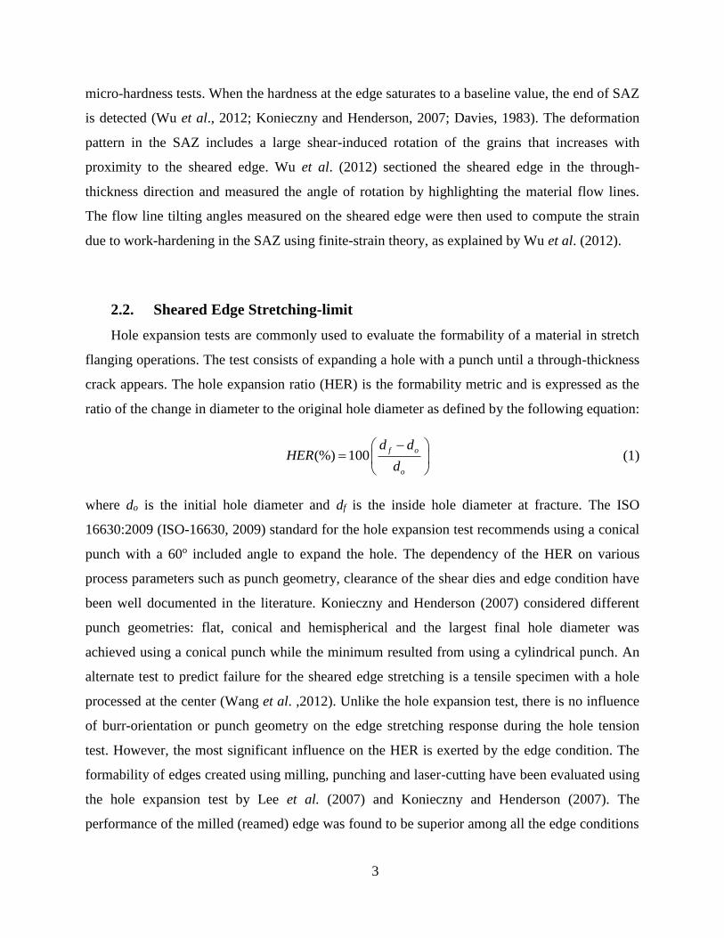
The fracture of ductile materials generally occurs through a process that involves nucleation,
growth and coalescence of microscopic voids and these mechanisms are illustrated in Figure 2. A
ductile material is typically comprised of second phase particles and/or inclusions in a matrix, in
some cases with pre-existing microscopic voids. During plastic deformation, additional cavities
are formed (void nucleation) and grow until they coalescence with neighboring voids to create
micro-cracks. These cracks propagate and coalescence with other cracks and this induced
damage causes rapid softening in the material leading to a localized neck and reduction in load
bearing capacity, ultimately causing fracture. The damage is often defined as the volume fraction
of voids in the aggregate material. The damage accumulation in AHSS steels was found to be
different than in conventional and mild steels due to their complex multiphase microstructure
(Erdogan, 2002; Avramovic-Cingara et al.., 2009). To enhance the performance of AHSS, a
thorough understanding of the fracture mechanism is required.
5
Figure 2: Ductile damage evolution, (a) Initial state; (b) void nucleation; (c) void growth; (d) void coalescence (Chen,
2004)
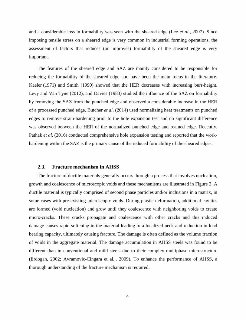
2.3.1. Void nucleation
In general, voids nucleate in ductile materials either by decohesion/debonding of the matrix
from an inclusion or hard particle, or when an inclusion or particle cracks. Void nucleation in DP
steels generally occurs through two mechanisms: decohesion of the ferrite-martensite interface
(shown in Figure 3) or fracture of martensite islands (Steinbrunner et al.., 1988; Erdogan, 2002;
Avramovic-Cingara et al., 2009). Ahmad et al. (2000) reported that at low-to-intermediate
volume fractions of martensite, void formation was due to ferrite-martensite decohesion; and at
higher volume fraction of martensite (above 32%) void nucleation occurs due to martensite
cracking. Additionally, Kadkhodapour et al. (2011a) observed the initiation of voids in DP steel
by the failure of ferrite grain boundaries and in the investigation by Erdogan (2002), voids were
formed in the vicinity of inclusions. Hence, the nucleation mechanism is different for each grade
of DP steel. Apart from the effect of microstructure, the influence of stress-state on void
nucleation has also been inferred experimentally (Hancock and Mackenzie, 1976; Landron et al.,
2010). Landron et al. (2010) quantified the nucleation of voids for two different DP600
specimens: tensile and higher triaxiality notch specimens and reported the influence of stress-
state on the void nucleation
6
Figure 3: Damage initiation mechanism at the vicinity of ferrite–martensite interface includes (a) micro-void initiation within the
ferrite phase followed by (b) void growth and decohesion, (c) decohesion along the interface (d) up to the final fracture where
some of the ferrite phase remains attached to the martensite island (Ghadbeigi et al., 2013)
2.3.2. Void growth and coalescence
Three main failure mechanisms are reported in ductile metals: a void coalescence process by
internal necking in the plane perpendicular to the applied load, a void-sheet mechanism by a
micro-void shear localization process and “necklace” coalescence of voids in the direction of
applied load as shown in Figure 4. The internal necking is more prominent under high stress-
triaxiality loading whereas the void-sheet mechanism is associated with low triaxiality conditions
as in shear loading. For AHSS, Kim and Thomas (1981) suggested that plastic deformation
begins in the ferrite while the martensite is still elastic. The local deformation/stress
concentration in the ferrite matrix leads to fracture of the ferrite matrix through cleavage or void
nucleation and coalescence depending on the microstructure (Steinbrunner et al., 1988). Micro-
voids initiate at the second phase particles or inclusions and, during deformation, grows and
eventually the ligament between the micro-voids fractures. Voids grow and coalescence
preferably along the plane normal to the applied load and were observed in the localized necking
region of the tensile specimen (Avramovic-Cingara et al., 2009). The results reported by Shih et
al. (2009) suggest that voids grow in the ferrite phase of DP steel. Kahziz et al. (2013) assessed
7
damage evolution of a DP600 sheared edge using laminography. However, the available studies
on AHSS grades have mostly focused on failure under proportional tensile loading.
Figure 4: Modes of void coalescence. (a) Necking of intervoid ligament or coalescence in a layer. (b),(c) Coalescence in a micro-
shear band. (d)“Necklace” coalescence or coalescence in columns. Major loading axis is vertical in all. Loading is axisymmetric
in (a)–(c) and plane strain in (d) (Benzerga, 2000)
Recently, x-ray tomography techniques have been used to observe void nucleation, growth
and coalescence in DP steel by the 3-D reconstruction of 2-D images (Landron et al., 2011,
2012, 2013). Figure 5 represents the bulk 3-D structure of a DP600 tensile specimen before
testing and just before fracture. Microstructural parameters such as the number of nucleated
voids, diameter and orientation of voids can be plotted as a function of strain. These relationships
can later be used for developing and validating damage-based constitutive models.
Figure 5: 3-D representation of the population of cavities inside the deforming sample in its initial state (a) and (b) just before
fracture (Landron et al., 2011, 2012, 2013)
8
2.4. Numerical Modeling of Ductile Failure
As discussed in the previous section, the typical ductile failure process consists of void
nucleation, followed by the growth of voids due to plastic straining and final coalescence of
voids. The following sections will focus on modeling the three stages of ductile fracture,
followed by the challenges in modeling the shear fracture mechanism.
2.4.1. Modeling of void nucleation
The conditions for the nucleation of voids from inclusions or second-phase particles have
been developed based on continuum and dislocation theory (Brown and Stobbs, 1971; Argon et
al., 1975; Goods and Brown, 1979; Fisher and Gurland, 1981). Gurson (1977) expressed his
nucleation rule in terms of equivalent plastic strain, based on Gurland’s (1972) experimental
results for nucleation in spheroidal steel. Chu and Needleman (1980) suggested that the stress or
strain required to nucleate voids follows a normal distribution and the strain-nucleation model
can be expressed as
(2)
where dεp is the equivalent plastic strain increment, fn is the fraction of void nucleating particles
and sN is the standard deviation of the nucleation strain. This strain based nucleation rule has
been widely used in the literature since it can be easily implemented in finite element models.
Fowler et al. (2000) and Butcher et al. (2006, 2009) used the stress-based Chu and Needleman
nucleation rule and suggested that the advantage of stress-based nucleation rule is that it is load-
path independent, unlike the strain-based nucleation rule. However, the main limitation of Chu
and Needleman strain-based nucleation model is that the influence of stress-state on void
nucleation is not considered.
2.4.2. Modeling void growth
The growth of a void within an infinite matrix was the earliest focus of study using
analytical approaches (McClintock, 1968; Rice and Tracey, 1969). McClintock (1968) analyzed
a cylindrical void in an infinite matrix and investigated void growth as a function of the remote
macroscopic strain. Rice and Tracey (1969) derived the void growth rule for spherical voids as a
2p
pNn
NN
1exp
22nucleation
fdf d
ss
9
function of stress triaxiality. The stress triaxiality is a representation of the severity of hydrostatic
loading and is defined as the ratio of the hydrostatic stress to the effective stress. Gurson (1977)
derived a pressure-dependent yield function by assuming the material to have a periodic
distribution of voids with each void contained in a spherical or cylindrical unit cell. Later,
Tvergaard (1981, 1982) introduced calibration parameters (q1, q2 and q3) to the Gurson yield
surface, resulting the commonly referred to GTN model as described in equation 3
(3)
where σM is the equivalent tensile flow stress and σeq and σhyd are the equivalent von Mises and
hydrostatic stress, respectively. There are some limitations with the Gurson model and a
significant effort has been made by various research groups (Mear and Hutchinson, 1985;
Leblond et al., 1995; Benzerga and Besson, 2001; Gologanu et al., 1993, 2012; Madou and
Leblond, 2012) to overcome them. Gologanu et al. (1993) extended the Gurson model by
considering the void shape effect and anisotropic behavior was introduced by Benzerga and
Besson (2001). The role of void clusters on void growth was investigated numerically by
Thomson et al. (1999) who suggested that severe stress- and strain-gradients were responsible
for the increased void growth and coalescence rates. To provide a void growth rule as a function
of void shape and stress states, Ragab (2004) summarized analytical and numerical simulation
results on a unit cell comprising voids of different shapes and under different stress conditions.
The effect of third stress invariant was not considered in the early constitutive models for ductile
porous materials but has gained more focus recently to account for low stress-triaxialities.
Nahshon and Hutchinson (2008) and Xue (2007) extended the Gurson (1977) model to
incorporate the third stress invariant by introducing an extra damage term that allows for failure
prediction even at zero hydrostatic tension.
2.4.3. Modeling void coalescence
A criterion for void coalescence was introduced by Tvergaard and Needleman (1984) based
on the assumption of a critical void volume fraction. However, this coalescence parameter was
found to be dependent on a variety of parameters, such as initial void volume fraction, stress
state and material hardening rate (Koplik and Needleman, 1988; Steglich and Brocks, 1998). The
physical mechanism of void coalescence in tensile stress states was theorized by considering a
2
eq hyd 2
1 2 3
M M
32 cosh 1 0
2fq q q f
10
competition between a stable, homogeneous deformation mode and an unstable, localized
deformation mode within the void ligaments resulting in necking failure (Thomason, 1985a,
1985b, 1990). This model of coalescence by internal necking has received widespread
acceptance (Pardoen and Hutchinson, 2000; Benzerga, 2002; Scheyvaerts et al. 2010; Benzerga
and Leblond 2014).
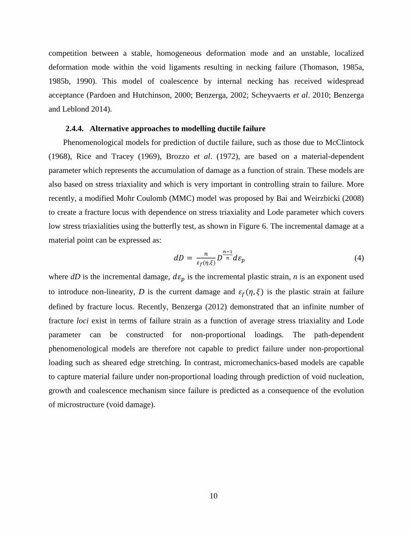
2.4.4. Alternative approaches to modelling ductile failure
Phenomenological models for prediction of ductile failure, such as those due to McClintock
(1968), Rice and Tracey (1969), Brozzo et al. (1972), are based on a material-dependent
parameter which represents the accumulation of damage as a function of strain. These models are
also based on stress triaxiality and which is very important in controlling strain to failure. More
recently, a modified Mohr Coulomb (MMC) model was proposed by Bai and Weirzbicki (2008)
to create a fracture locus with dependence on stress triaxiality and Lode parameter which covers
low stress triaxialities using the butterfly test, as shown in Figure 6. The incremental damage at a
material point can be expressed as:
𝑑𝐷 = 𝑛
𝜀𝑓(𝜂,𝜉)𝐷𝑛−1
𝑛 𝑑𝜀𝑝 (4)
where dD is the incremental damage, 𝑑𝜀𝑝 is the incremental plastic strain, n is an exponent used
to introduce non-linearity, D is the current damage and 𝜀𝑓(𝜂, 𝜉) is the plastic strain at failure
defined by fracture locus. Recently, Benzerga (2012) demonstrated that an infinite number of
fracture loci exist in terms of failure strain as a function of average stress triaxiality and Lode
parameter can be constructed for non-proportional loadings. The path-dependent
phenomenological models are therefore not capable to predict failure under non-proportional
loading such as sheared edge stretching. In contrast, micromechanics-based models are capable
to capture material failure under non-proportional loading through prediction of void nucleation,
growth and coalescence mechanism since failure is predicted as a consequence of the evolution
of microstructure (void damage).
11
Figure 6: Modified Mohr-Column fracture locus for plane stress conditions, plotted on the plane of equivalent strain to fracture
versus stress-triaxiality (Bai and Weirzbicki, 2008)
2.5. Finite element simulation of the hole expansion test
Extensive work has been done to predict the onset of fracture and crack initiation during
edge stretching simulations (Takuda et al., 1999 Worswick and Finn, 2000; Uthaisangsuk et al.,
2009b; Hashimoto et al., 2010; Kim et al., 2010; Xu et al., 2010; Xu et al., 2012; Choi et al.,
2014; Paul et al., 2014). Efforts have been made to develop anisotropic model for the hole
expansion test in order to capture localized necking preceding fracture accurately (Hashimoto et
al., 2010; Xu et al., 2010; 2012). Various researchers have correlated the failure mechanism of
the tensile test with the hole expansion test (Adamczyk and Michal, 1986). A fracture-based
failure criterion was developed by Paul et al. (2014), using true fracture strain from the tensile
test and the formation of a through-thickness crack as the limit criterion for the hole expansion
test.
Most of the numerical models of edge stretching have focused on the edge failure of
reamed/milled holes and limited work has been done considering simulation of actual sheared
edges. A ductile fracture criterion based on the equivalent strain in notch tensile tests was
developed by Lee et al. (2007) to simulate hole expansion of punched and reamed edges. The
experiments were performed on the notched sample with reamed and punched cut-outs to predict
the failure strain of the respective edges. However, recent work (Bai and Wierzbicki, 2008) has

12
shown that failure strains are stress state-dependent and that applying fracture strains obtained
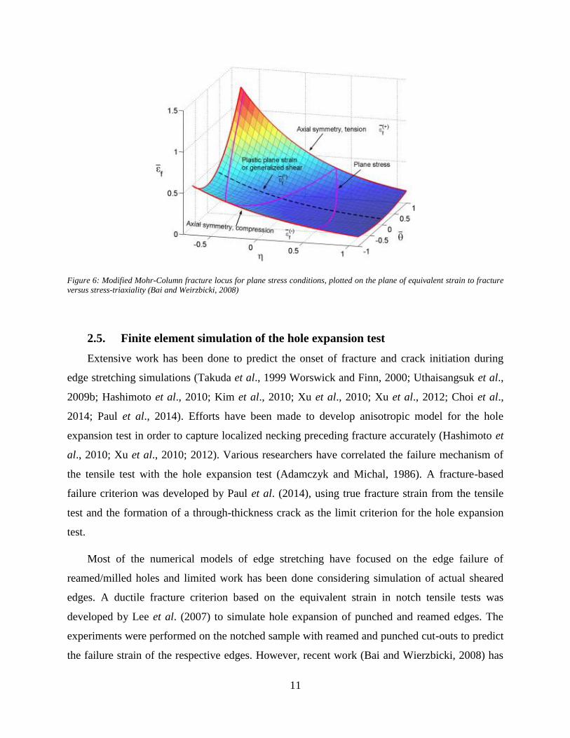
from one stress condition to the other is not an accurate technique. An axisymmetric model of
hole expansion test was developed by Butcher et al. (2013) (shown in Figure 7) and the effect of
shearing/blanking was accounted by the value of initial porosity and strain hardening. Efforts
have been made to model the multi-stage simulation process by various researchers using
different damage models (Goijaerts et al., 2001; Rachik et al., 2002; Chen et al., 2002; Hu et al.,
2014; Wang et al. 2016) but little work has been done so far to transfer experimentally measured
pre-strains formed during the shearing process to the simulation of the hole expansion test.
Figure 7: Finite element model of the hole expansion test showing predicted contours of equivalent stress (Butcher et al., 2013)
2.6. Current state of knowledge in the sheared edge stretching
The quality of the sheared edge is dependent on the parameters of the shearing process and
is reflected in the surface roughness at the sheared edge, the size of the shear-burr, and extent of
pre-straining and damage in the SAZ. These characteristics result as a consequence of
deformation during shearing and the damage mechanisms occurring in a material and therefore
the performance of a sheared edge in stretch-flanging operations is strongly related to the
microstructure of material. In AHSS, particularly DP steel, the level of work-hardening and
damage in the SAZ is increased due to the severe stress-gradient between the ferrite and
martensite grains. Recent results available in the literature have shown that ferritic-bainitic alloys
could be promising alternatives to dual phase steels in industrial stretch-flanging operations since
they offer a lower local stress-gradient and therefore a better HER than a ferritic-martensitic DP
steel (Murata et. al., 2010; Konieczny and Henderson, 2007). However, there is a lack of
published research addressing the characterization of the microstructural response and
13
mechanical performance of ferritic-bainitic alloys in stretch-flanging operations. To establish
ferritic-bainitic alloy such as CP steel in industrial stretch-flanging operations, there is a need to
characterize the mechanical properties, edge-stretchability and damage mechanisms of this alloy.
Although there has been a lot of work done on the numerical simulation of the stretch-
flanging operations, the main emphasis in the available literature has been to predict crack
formation at the machined edge by using suitable yield and damage criteria. In industry, holes
are mostly sheared prior to stretching and sheared edge stretching is a non-proportional loading
that likely requires a microstructure- and stress state-dependent fracture model to predict failure.
The published work on the simulation of the hole expansion test for sheared edges has used
fracture strain criteria with only limited consideration of the stress-state and for an accurate
prediction of the edge stretching limit, an alternate method is required. Researchers have focused
on modeling sequential shearing and stretching simulation to predict sheared edge failure.
However, there are some challenges associated with modeling the shearing process such as mesh
sensitivity and dependence of the predictions upon the assumed fracture model and calibration
parameters. Additionally, high computational cost limits the application of finite element models
to practical forming simulations of components with a complex geometry. More importantly, the
predicted strain from shearing simulation needs to be validated. For a material designer seeking
to optimize the microstructure and thermal processing/chemistry, further insight into the
mechanism controlling the fracture process is necessary. A micromechanics-based ductile
fracture model can be promising for modeling the sheared edge stretching, but will require
quantification and characterization of strain hardening and damage at the sheared edge.
14
3. Objective
The overall aim of this research is to develop a damage-based fracture model to predict the
sheared edge stretchability of AHSS. To this end, studies of the sheared edge stretchability of
two AHSS with differing microstructures have been undertaken: (i) a production-trial CP steel
with a predominantly ferritic-baintitic microstructure; and, (ii) a commercial DP steel with a
ferritic-martensitic microstructure.
Within this overall aim, five primary objectives were addressed:
1. Evaluate the stretch-flangeability of CP and DP steels and investigate the factors that
control sheared edge stretchability in these alloys;
2. Characterize the operative damage mechanisms and investigate the role of microstructure
in influencing the fracture of DP and CP steels;
3. Develop experimental techniques to quantify the strain-distribution introduced during the
shearing process;
4. Develop a stress state-dependent damage nucleation model; and,
5. Develop a micromechanics-based damage model to predict sheared edge failure.
Work done in support of these objectives is summarized in the following sections of this
synopsis.
15
4. Summary of the Research Results
Five tasks were undertaken that were aligned with the research objectives stated in Section 3
of this thesis. This section, presents a summary of the research results from each task and is
presented in five parts:
Part 1 Assessment of the Critical Parameters Influencing the Edge Stretchability
of Advanced High Strength Steel Sheet
Part 2 Damage Evolution in Complex-Phase and Dual-Phase Steels during Edge
Stretching
Part 3 Experimental Techniques for Residual Shear Strain Measurement with
Applications to Sheared Edge Stretching of Advanced High Strength Steel
Part 4 Experimental Stress State-Dependent Void Nucleation Behaviour for Two
800 MPa Advanced High Strength Steels
Part 5 Micro-mechanics Based Fracture Model to Predict Edge Failure in 800
MPa Advanced High Strength Steels
Each part is documented in a peer reviewed accepted or submitted journal publication, all
five of which are appended to this thesis. This synopsis presents a summary of these publications
along with an overall discussion of the results, followed by conclusions and recommendations
stemming from this research.
16
4.1. Assessment of the Critical Parameters Influencing the Edge Stretchability
of Advanced High Strength Steel Sheet
The edge formability of a range of AHSS, namely DP600, DP780, CP590 and CP800, is
considered (detailed description of the alloys is provided in Appendix A). Both hole expansion
and hole extrusion conditions were considered by expanding 10 mm holes using a standard
conical punch, as recommended by ISO standards, and a custom-made flat punch. To isolate the
influence of work-hardening and surface roughness introduced behind the sheared edge, three
edge conditions were considered: drilled and reamed, sheared, and sheared and polished. The
punched holes were sheared using a 12% clearance in accordance with the JFS-1001 (1996)
standard. The hole expansion testing was conducted at ArcelorMittal Dofasco facility in
Hamilton, Ontario and the test was terminated when a through-thickness crack was observed.
4.1.1. Influence of the Punch Geometry
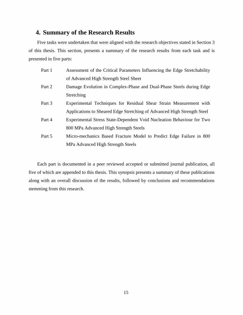
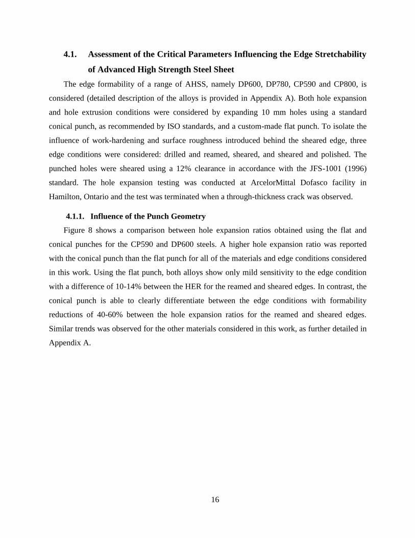
Figure 8 shows a comparison between hole expansion ratios obtained using the flat and
conical punches for the CP590 and DP600 steels. A higher hole expansion ratio was reported
with the conical punch than the flat punch for all of the materials and edge conditions considered
in this work. Using the flat punch, both alloys show only mild sensitivity to the edge condition
with a difference of 10-14% between the HER for the reamed and sheared edges. In contrast, the
conical punch is able to clearly differentiate between the edge conditions with formability
reductions of 40-60% between the hole expansion ratios for the reamed and sheared edges.
Similar trends was observed for the other materials considered in this work, as further detailed in
Appendix A.
17
Figure 8: HER values for the reamed and sheared edges expanded by the flat and conical punches for the materials (a) CP590
and (b) DP600.
4.1.2. Influence of the Edge Condition
Figure 9 shows the HER for the reamed and punched-polished edge conditions for the CP
and DP steels. The considerable difference in the edge formability of the two edge conditions for
all of the materials is observed and attributed to the presence of pre-strain (work-hardening) and
nucleated voids in the SAZ that leads to premature failure in the sheared edge. This observation
suggests that the presence of the SAZ plays a prominent role in influencing formability of the
sheared edge.

18
Figure 9: Hole expansion ratios of the CP and DP steels with the sheared-polished and sheared edge conditions (the error bars
shows the 95% confidence intervals)
The influence of the surface roughness is studied by comparing the HER for the punched
and punched-polished edges. As shown in Figure 10, the confidence intervals of the HER for the
two edge types overlap and suggests that there is no significant difference between the
stretchability of the two edges. This result implies that the surface roughness at the sheared edge
has minor or secondary influence on the HER.
Figure 10: Hole expansion ratios of the CP steels with the sheared-polished and sheared edge conditions (the error bars shows
the 95% confidence intervals)
19
4.2. Damage Evolution in Complex-Phase and Dual-Phase Steels during Edge
Stretching
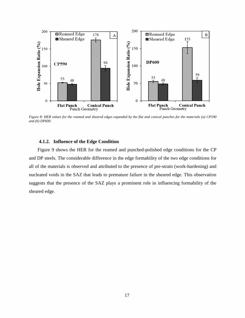
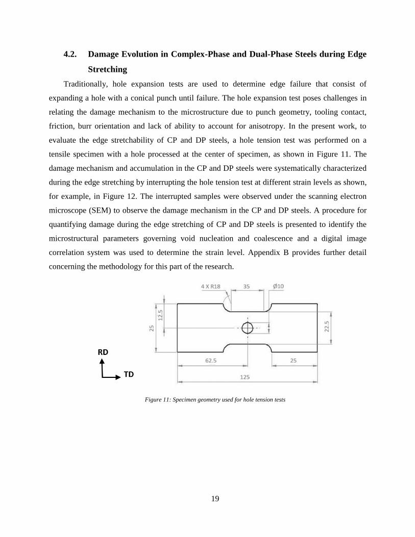
Traditionally, hole expansion tests are used to determine edge failure that consist of
expanding a hole with a conical punch until failure. The hole expansion test poses challenges in
relating the damage mechanism to the microstructure due to punch geometry, tooling contact,
friction, burr orientation and lack of ability to account for anisotropy. In the present work, to
evaluate the edge stretchability of CP and DP steels, a hole tension test was performed on a
tensile specimen with a hole processed at the center of specimen, as shown in Figure 11. The
damage mechanism and accumulation in the CP and DP steels were systematically characterized
during the edge stretching by interrupting the hole tension test at different strain levels as shown,
for example, in Figure 12. The interrupted samples were observed under the scanning electron
microscope (SEM) to observe the damage mechanism in the CP and DP steels. A procedure for
quantifying damage during the edge stretching of CP and DP steels is presented to identify the
microstructural parameters governing void nucleation and coalescence and a digital image
correlation system was used to determine the strain level. Appendix B provides further detail
concerning the methodology for this part of the research.
Figure 11: Specimen geometry used for hole tension tests
20
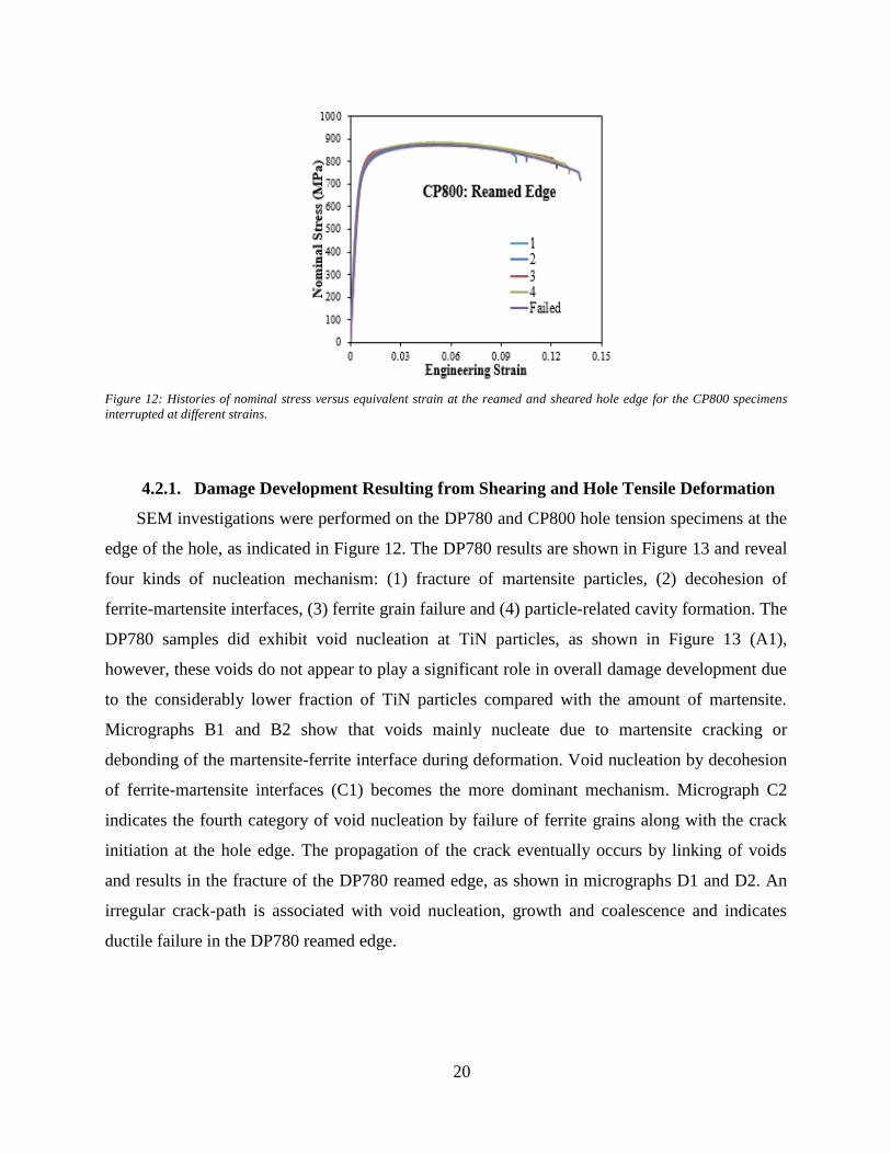
Figure 12: Histories of nominal stress versus equivalent strain at the reamed and sheared hole edge for the CP800 specimens
interrupted at different strains.
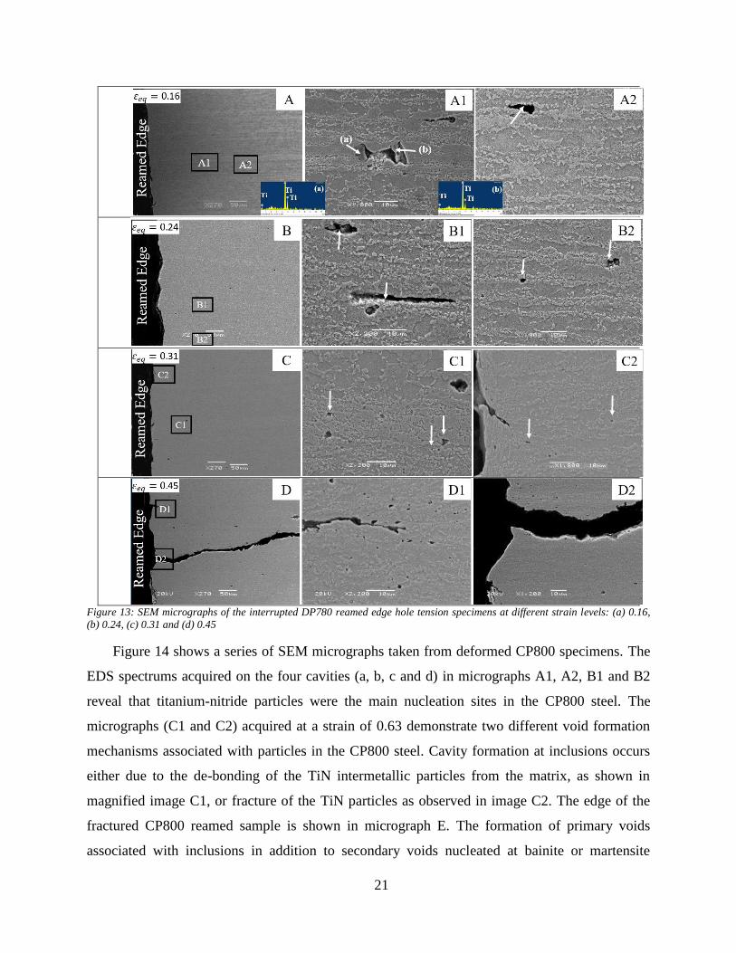
4.2.1. Damage Development Resulting from Shearing and Hole Tensile Deformation
SEM investigations were performed on the DP780 and CP800 hole tension specimens at the
edge of the hole, as indicated in Figure 12. The DP780 results are shown in Figure 13 and reveal
four kinds of nucleation mechanism: (1) fracture of martensite particles, (2) decohesion of
ferrite-martensite interfaces, (3) ferrite grain failure and (4) particle-related cavity formation. The
DP780 samples did exhibit void nucleation at TiN particles, as shown in Figure 13 (A1),
however, these voids do not appear to play a significant role in overall damage development due
to the considerably lower fraction of TiN particles compared with the amount of martensite.
Micrographs B1 and B2 show that voids mainly nucleate due to martensite cracking or
debonding of the martensite-ferrite interface during deformation. Void nucleation by decohesion
of ferrite-martensite interfaces (C1) becomes the more dominant mechanism. Micrograph C2
indicates the fourth category of void nucleation by failure of ferrite grains along with the crack
initiation at the hole edge. The propagation of the crack eventually occurs by linking of voids
and results in the fracture of the DP780 reamed edge, as shown in micrographs D1 and D2. An
irregular crack-path is associated with void nucleation, growth and coalescence and indicates
ductile failure in the DP780 reamed edge.
21
Figure 13: SEM micrographs of the interrupted DP780 reamed edge hole tension specimens at different strain levels: (a) 0.16,
(b) 0.24, (c) 0.31 and (d) 0.45
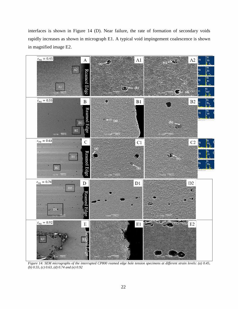
Figure 14 shows a series of SEM micrographs taken from deformed CP800 specimens. The
EDS spectrums acquired on the four cavities (a, b, c and d) in micrographs A1, A2, B1 and B2
reveal that titanium-nitride particles were the main nucleation sites in the CP800 steel. The
micrographs (C1 and C2) acquired at a strain of 0.63 demonstrate two different void formation
mechanisms associated with particles in the CP800 steel. Cavity formation at inclusions occurs
either due to the de-bonding of the TiN intermetallic particles from the matrix, as shown in
magnified image C1, or fracture of the TiN particles as observed in image C2. The edge of the
fractured CP800 reamed sample is shown in micrograph E. The formation of primary voids
associated with inclusions in addition to secondary voids nucleated at bainite or martensite
22
interfaces is shown in Figure 14 (D). Near failure, the rate of formation of secondary voids
rapidly increases as shown in micrograph E1. A typical void impingement coalescence is shown
in magnified image E2.
Figure 14: SEM micrographs of the interrupted CP800 reamed edge hole tension specimens at different strain levels: (a) 0.45,
(b) 0.55, (c) 0.63, (d) 0.74 and (e) 0.92
T
i
23
The nucleation mechanism for a particular alloy did not change with edge condition; the
effect of shearing was to locally harden the edge that increased the rate of nucleation. The role of
void evolution in the premature failure of the sheared edge is reflected in the crack propagation
mechanism. During deformation of the reamed edge, crack initiation and propagation occur over
a small range of strain near the fracture strain. In contrast, cracks initiate at the sheared edge
during the early stages of deformation (Appendix B).
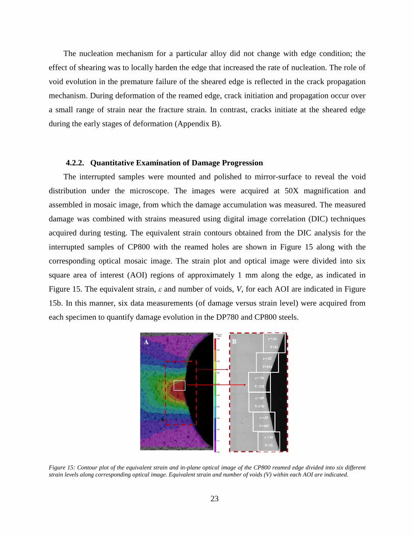
4.2.2. Quantitative Examination of Damage Progression
The interrupted samples were mounted and polished to mirror-surface to reveal the void
distribution under the microscope. The images were acquired at 50X magnification and
assembled in mosaic image, from which the damage accumulation was measured. The measured
damage was combined with strains measured using digital image correlation (DIC) techniques
acquired during testing. The equivalent strain contours obtained from the DIC analysis for the
interrupted samples of CP800 with the reamed holes are shown in Figure 15 along with the
corresponding optical mosaic image. The strain plot and optical image were divided into six
square area of interest (AOI) regions of approximately 1 mm along the edge, as indicated in
Figure 15. The equivalent strain, ε and number of voids, V, for each AOI are indicated in Figure
15b. In this manner, six data measurements (of damage versus strain level) were acquired from
each specimen to quantify damage evolution in the DP780 and CP800 steels.
Figure 15: Contour plot of the equivalent strain and in-plane optical image of the CP800 reamed edge divided into six different
strain levels along corresponding optical image. Equivalent strain and number of voids (V) within each AOI are indicated.
24
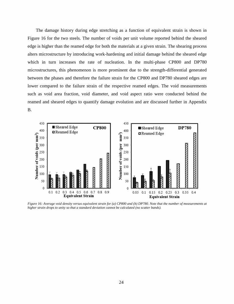
The damage history during edge stretching as a function of equivalent strain is shown in
Figure 16 for the two steels. The number of voids per unit volume reported behind the sheared
edge is higher than the reamed edge for both the materials at a given strain. The shearing process
alters microstructure by introducing work-hardening and initial damage behind the sheared edge
which in turn increases the rate of nucleation. In the multi-phase CP800 and DP780
microstructures, this phenomenon is more prominent due to the strength-differential generated
between the phases and therefore the failure strain for the CP800 and DP780 sheared edges are
lower compared to the failure strain of the respective reamed edges. The void measurements
such as void area fraction, void diameter, and void aspect ratio were conducted behind the
reamed and sheared edges to quantify damage evolution and are discussed further in Appendix
B.
Figure 16: Average void density versus equivalent strain for (a) CP800 and (b) DP780. Note that the number of measurements at
higher strain drops to unity so that a standard deviation cannot be calculated (no scatter bands).
25
4.3. Experimental Techniques for Residual Shear Strain Measurement with
Applications to Sheared Edge Stretching of Advanced High Strength
Steel
The experimental work discussed in section 4.1 has shown that the formability of the
sheared edge is mainly controlled by the SAZ which is formed as a result of severe pre-straining.
To define the SAZ in a finite element model, quantitative characterization of the level of pre-
straining is needed. The development of experimental techniques to quantify the strain
distribution within sheared complex-phase and dual-phase steels of a similar strength level of
800 MPa is presented in this section and Appendix C.
4.3.1. Correlating Shear Angle and Hardness Measurement with Shear Strain using
Shear Test
Two independent experimental techniques were proposed to characterize the residual strain
distribution within the shear-affected zone based on (i) the grain rotation along the shear
direction and (ii) the work hardening introduced during shear deformation, using microhardness
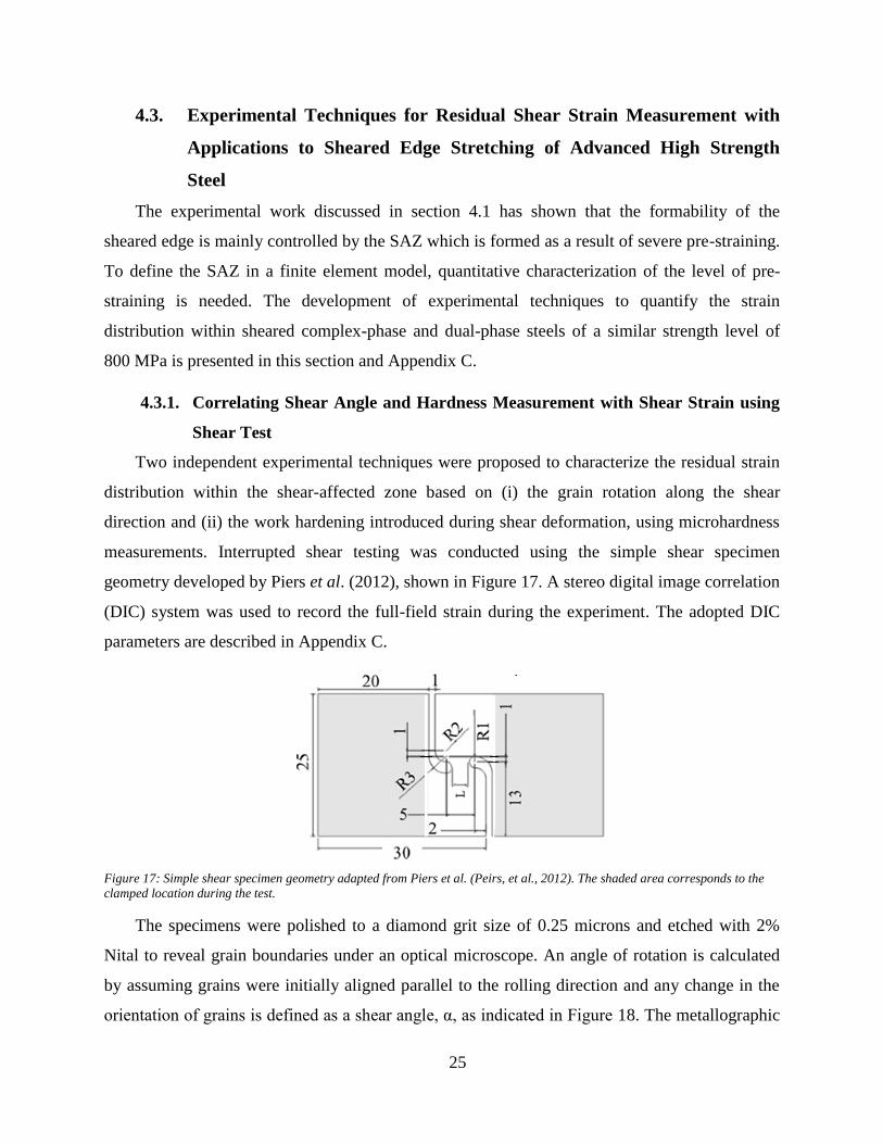
measurements. Interrupted shear testing was conducted using the simple shear specimen
geometry developed by Piers et al. (2012), shown in Figure 17. A stereo digital image correlation
(DIC) system was used to record the full-field strain during the experiment. The adopted DIC
parameters are described in Appendix C.
Figure 17: Simple shear specimen geometry adapted from Piers et al. (Peirs, et al., 2012). The shaded area corresponds to the
clamped location during the test.
The specimens were polished to a diamond grit size of 0.25 microns and etched with 2%
Nital to reveal grain boundaries under an optical microscope. An angle of rotation is calculated
by assuming grains were initially aligned parallel to the rolling direction and any change in the
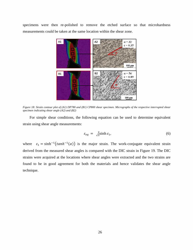
orientation of grains is defined as a shear angle, α, as indicated in Figure 18. The metallographic
26
specimens were then re-polished to remove the etched surface so that microhardness
measurements could be taken at the same location within the shear zone.
Figure 18: Strain contour plot of (A1) DP780 and (B1) CP800 shear specimen. Micrographs of the respective interrupted shear
specimen indicating shear angle (A2) and (B2)
For simple shear conditions, the following equation can be used to determine equivalent
strain using shear angle measurements:
𝜀𝑒𝑞 = sinh 𝜀1√32 , (6)
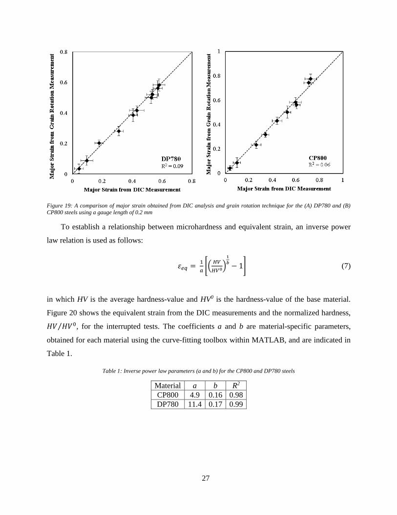
where 𝜀1 = sinh−1(𝑡𝑎𝑛ℎ−1(𝛼)) is the major strain. The work-conjugate equivalent strain
derived from the measured shear angles is compared with the DIC strain in Figure 19. The DIC
strains were acquired at the locations where shear angles were extracted and the two strains are
found to be in good agreement for both the materials and hence validates the shear angle
technique.
27
Figure 19: A comparison of major strain obtained from DIC analysis and grain rotation technique for the (A) DP780 and (B)
CP800 steels using a gauge length of 0.2 mm
To establish a relationship between microhardness and equivalent strain, an inverse power
law relation is used as follows:
𝜀𝑒𝑞 = 1
𝑎[(
𝐻𝑉
𝐻𝑉0)
1
𝑏− 1] (7)
in which HV is the average hardness-value and HV0 is the hardness-value of the base material.
Figure 20 shows the equivalent strain from the DIC measurements and the normalized hardness,
𝐻𝑉 𝐻𝑉0⁄ , for the interrupted tests. The coefficients a and b are material-specific parameters,
obtained for each material using the curve-fitting toolbox within MATLAB, and are indicated in
Table 1.
Table 1: Inverse power law parameters (a and b) for the CP800 and DP780 steels
Material a b R2
CP800 4.9 0.16 0.98
DP780 11.4 0.17 0.99
28
Figure 20: Variation in the equivalent strain with the normalized microhardness for (a) CP800 and (b) DP780 steel
4.3.2. Characterization of the Sheared Edge
The sheared edges were sectioned, mounted, polished and etched using 2% Nital to reveal
grain rotation. A shear angle, α, was measured across the SAZ by drawing a line of approximate
length 20 µm as indicated in Figure 21. The sheared edge was re-polished and microhardness
measurements were then taken on the sheared edge in the form of an interlocking grid covering
the SAZ as shown in Figure 21. Similar measurements were conducted for the DP780 sheared
edge.
Figure 21: Sheared edge of CP800 indicating hardness mapping and Nital etch to highlight grain rotation. A 12% punch
clearance was used to shear a hole of diameter 10 mm
The shear angle measurements were conducted behind the CP800 and DP780 sheared edges
(at 12% clearance) by drawing lines along the grain boundaries and converting to equivalent
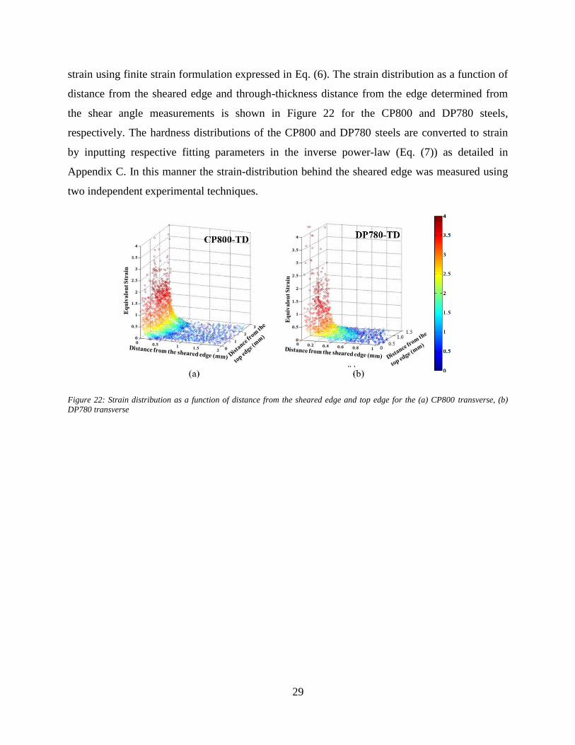
29
strain using finite strain formulation expressed in Eq. (6). The strain distribution as a function of
distance from the sheared edge and through-thickness distance from the edge determined from
the shear angle measurements is shown in Figure 22 for the CP800 and DP780 steels,
respectively. The hardness distributions of the CP800 and DP780 steels are converted to strain
by inputting respective fitting parameters in the inverse power-law (Eq. (7)) as detailed in
Appendix C. In this manner the strain-distribution behind the sheared edge was measured using
two independent experimental techniques.
Figure 22: Strain distribution as a function of distance from the sheared edge and top edge for the (a) CP800 transverse, (b)
DP780 transverse
30
4.4. Experimental Stress State-Dependent Void Nucleation Behaviour for Two
800 MPa Advanced High Strength Steels
This section describes the influence of loading conditions on void nucleation and a stress-
dependent nucleation model is developed based on measured tomography data. The four
characterization tests performed in the current study were equi-biaxial Nakazima, v-bend, hole
tension and simple shear tests that correspond to strain states ranging from simple shear to
biaxial tension, as shown in Figure 23. Each characterization test was interrupted at four different
strain levels prior to fracture. The region of the maximum deformation was extracted and 3D
micro-tomography was conducted paired with in situ digital image correlation (DIC) strain
measurements to construct damage histories from the mechanical testing. The damage
development is extensive based on the tomographs from interrupted hole tension specimens near
the failure strain, as shown in Figure 24. More detailed presentation of the tomographs for both
alloys and edge conditions is provided in Appendix D.
Figure 23: Major and minor strains paths in the region of maximum deformation subjected to different loading conditions for the
(a) CP800 and (b) DP780 steels
31
Figure 24: 3D views of damage within the (a) CP800 and (b) DP780 hole tension specimens deformed near failure
4.4.1. Damage Evolution under Proportional Loading
The number of voids nucleated as a function of equivalent strain for the different loading
conditions is shown in Figure 25. A continuous increase in the number of nucleated voids was
observed for all the stress-states. The maximum nucleation rate occurs under biaxial tension and
the minimum cavity formation rate was observed under shear loading for both alloys which
suggests an influence of stress-state on void nucleation. This trend is in agreement with the
results reported by Landron et al. (2012)
(a)
(b)
Figure 25: Average void density versus equivalent strain for (a) CP800 and (b) DP780 steels (symbols). Solid lines are
predictions using Lode parameter-dependent strain-based Chu and Needleman nucleation rule using Eq. (8 for the various
loading conditions of the (a) CP800 and (b) DP780 steels.
32
4.4.2. Void Nucleation Model
To capture the influence of loading condition on the void nucleation, a modification to the
Chu and Needleman nucleation criterion is proposed and expressed in the following equation:
�̇� = 𝑁𝑛𝑠𝑁√2𝜋
𝑒𝑥𝑝 [−12(𝜀𝑝−𝜀𝑁(𝑇,𝐿)
𝑠𝑁)2] �́�𝑝 (8a)
𝑐𝑣 = 𝜀𝑁
𝑠𝑁 (8b)
where �̇� is the void nucleation rate, Nn is the maximum number of voids per unit volume
available to nucleation voids, εN and sN are the mean and standard deviation of the nucleation
strain, 𝑐𝑣 is the coefficient of variation of nucleation strain and εp is the Von Mises equivalent
plastic strain. The nucleation strain, εN, was determined individually for each loading condition
as a function of stress-triaxiality as well as Lode parameter and listed in Table 2. The Nn and
coefficient of variation are assumed to be material-dependent and hence considered same for all
the loading conditions.
Table 2: Nucleation parameters for the different stress-states of the CP800 and DP780 steels
Material Nn
(per mm3)
cv
Biaxial Tension Plane Strain Uniaxial Tension Shear
εN T L εN T L εN T L εN T L
CP800 397942 0.24 1.10 0.66 0.97 1.34 0.55 -0.01 1.58 0.30 -0.92 2.20 0.00 0.02
DP780 62000 0.22 0.55 0.66 0.98 0.60 0.55 0.01 0.70 0.55 -0.98 1.20 0.00 0.01
In order to predict the nucleation rate for a broad range of stress-states, a nucleation strain
“surface” is introduced in which nucleation strain is cast as a function of stress-triaxiality (T) and
Lode parameter (L). The nucleation surface was developed as an adaptation of the Bai and
Wierzbicki (2008) fracture locus (Eq, (9)), but here used to predict nucleation strain as a function
of stress state and expressed as:
𝜀𝑁 =
{
𝐶1
𝐶2[𝐶3 +
√3
2−√3(1 − 𝐶3) (sec (
𝜋𝐿
6) − 1)]
× [√1+ 𝐶4
2
3cos (
𝜋𝐿
6) + 𝐶4 (𝑇 +
1
3sin (
𝜋𝐿
6))]}
−1
𝐶5
(9)
where 𝐶1−5 are material parameters (given in Appendix D). Figure 26 shows the nucleation
surface for the CP800 and DP780 steels that covers a broad range of stress-states. The nucleation
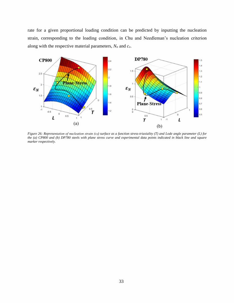
33
rate for a given proportional loading condition can be predicted by inputting the nucleation
strain, corresponding to the loading condition, in Chu and Needleman’s nucleation criterion
along with the respective material parameters, Nn and cv.
Figure 26: Representation of nucleation strain (εN) surface as a function stress-triaxiality (T) and Lode angle parameter (L) for
the (a) CP800 and (b) DP780 steels with plane stress curve and experimental data points indicated in black line and square
marker respectively.
34
4.5. Micro-Mechanics based Fracture Model to Predict Edge Failure in 800
MPa Advanced High Strength Steels
3D tomography was conducted on CP800 and DP780 hole tension specimens with both
reamed and sheared holes to capture the influence of edge condition on damage evolution. The
resulting trends for void nucleation, growth and coalescence were used to calibrate a physically-
motivated damage model which was applied in two stages to simulate the shearing process
followed by the subsequent hole tension experiment. The shearing process model utilized the
measured shear strain distributions at the hole edge, presented in Section 4.3. The damage
constitutive model was integrated for the pre-strains around the sheared edge, thereby
establishing an “initial sheared edge condition” that was used to initialize a finite element model
of the hole tension experiments. The reamed edge condition was also modelled by simply
running the hole tension simulation without initializing the sheared edge condition. This
modeling approach was validated by comparing the predicted strain distributions and damage
with the corresponding experimental measurements from hole tension samples for the different
edge conditions.
4.5.1. Damage Evolution during the Edge Stretching
The damage history during the sheared edge stretching as a function of equivalent strain is
shown in Figure 27 for the two steels. This data was extracted from tomography measurement
described in Appendix E. The number of voids per unit volume reported behind the sheared edge
is higher than for the reamed edge for both the materials at a given strain. The shearing process
alters microstructure by introducing work-hardening and initial damage behind the sheared edge
which in turn increases the rate of nucleation. In the multi-phase CP800 and DP780
microstructures, this phenomenon is more prominent due to the strength-differential generated
between the phases. Thus, the failure strains for the CP800 and DP780 sheared edges are lower
compared to the failure strain of the respective reamed edges.
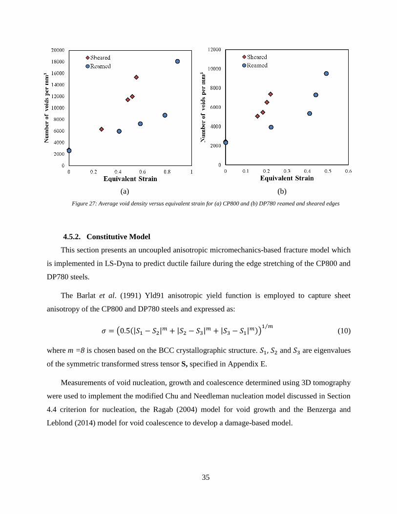
35
(a)
(b)
Figure 27: Average void density versus equivalent strain for (a) CP800 and (b) DP780 reamed and sheared edges
4.5.2. Constitutive Model
This section presents an uncoupled anisotropic micromechanics-based fracture model which
is implemented in LS-Dyna to predict ductile failure during the edge stretching of the CP800 and
DP780 steels.
The Barlat et al. (1991) Yld91 anisotropic yield function is employed to capture sheet
anisotropy of the CP800 and DP780 steels and expressed as:
𝜎 = (0.5(|𝑆1 − 𝑆2|𝑚 + |𝑆2 − 𝑆3|
𝑚 + |𝑆3 − 𝑆1|𝑚))
1 𝑚⁄ (10)
where m =8 is chosen based on the BCC crystallographic structure. 𝑆1, 𝑆2 and 𝑆3 are eigenvalues
of the symmetric transformed stress tensor S, specified in Appendix E.
Measurements of void nucleation, growth and coalescence determined using 3D tomography
were used to implement the modified Chu and Needleman nucleation model discussed in Section
4.4 criterion for nucleation, the Ragab (2004) model for void growth and the Benzerga and
Leblond (2014) model for void coalescence to develop a damage-based model.
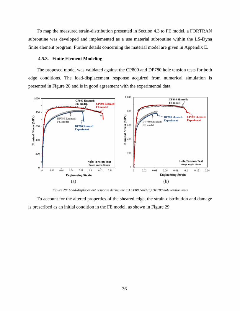
36
To map the measured strain-distribution presented in Section 4.3 to FE model, a FORTRAN
subroutine was developed and implemented as a use material subroutine within the LS-Dyna
finite element program. Further details concerning the material model are given in Appendix E.
4.5.3. Finite Element Modeling
The proposed model was validated against the CP800 and DP780 hole tension tests for both
edge conditions. The load-displacement response acquired from numerical simulation is
presented in Figure 28 and is in good agreement with the experimental data.
Figure 28: Load-displacement response during the (a) CP800 and (b) DP780 hole tension tests
To account for the altered properties of the sheared edge, the strain-distribution and damage
is prescribed as an initial condition in the FE model, as shown in Figure 29.
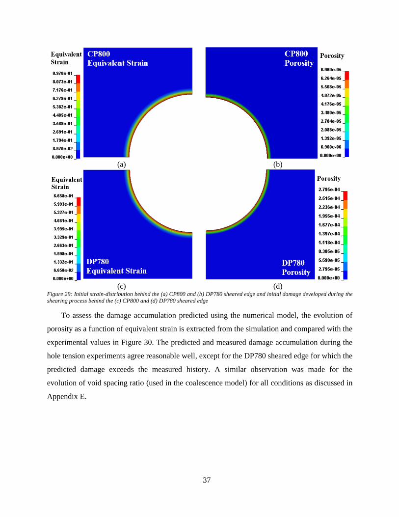
37
(a)
(b)
(c)
(d)
Figure 29: Initial strain-distribution behind the (a) CP800 and (b) DP780 sheared edge and initial damage developed during the
shearing process behind the (c) CP800 and (d) DP780 sheared edge
To assess the damage accumulation predicted using the numerical model, the evolution of
porosity as a function of equivalent strain is extracted from the simulation and compared with the
experimental values in Figure 30. The predicted and measured damage accumulation during the
hole tension experiments agree reasonable well, except for the DP780 sheared edge for which the
predicted damage exceeds the measured history. A similar observation was made for the
evolution of void spacing ratio (used in the coalescence model) for all conditions as discussed in
Appendix E.
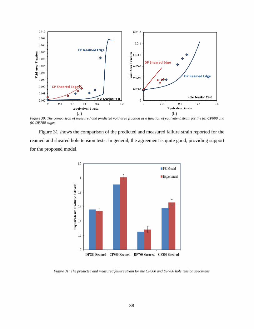
38
(a)
(b)
Figure 30: The comparison of measured and predicted void area fraction as a function of equivalent strain for the (a) CP800 and
(b) DP780 edges
Figure 31 shows the comparison of the predicted and measured failure strain reported for the
reamed and sheared hole tension tests. In general, the agreement is quite good, providing support
for the proposed model.
Figure 31: The predicted and measured failure strain for the CP800 and DP780 hole tension specimens
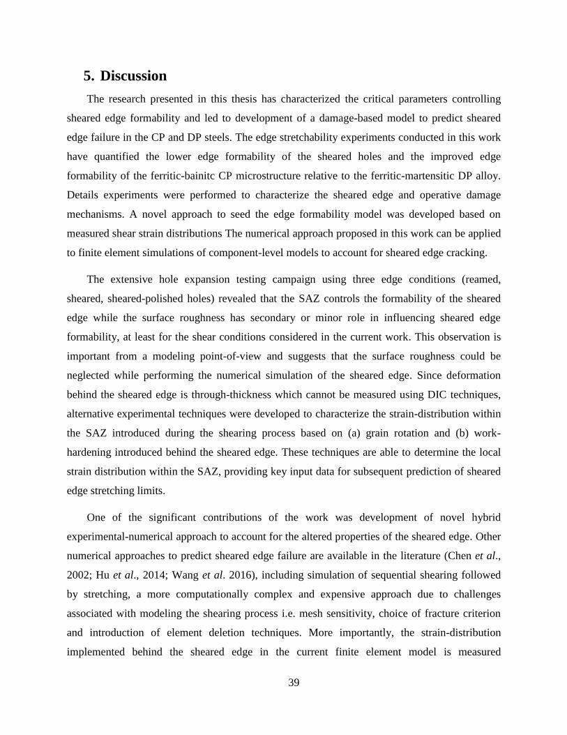
39
5. Discussion
The research presented in this thesis has characterized the critical parameters controlling
sheared edge formability and led to development of a damage-based model to predict sheared
edge failure in the CP and DP steels. The edge stretchability experiments conducted in this work
have quantified the lower edge formability of the sheared holes and the improved edge
formability of the ferritic-bainitc CP microstructure relative to the ferritic-martensitic DP alloy.
Details experiments were performed to characterize the sheared edge and operative damage
mechanisms. A novel approach to seed the edge formability model was developed based on
measured shear strain distributions The numerical approach proposed in this work can be applied
to finite element simulations of component-level models to account for sheared edge cracking.
The extensive hole expansion testing campaign using three edge conditions (reamed,
sheared, sheared-polished holes) revealed that the SAZ controls the formability of the sheared
edge while the surface roughness has secondary or minor role in influencing sheared edge
formability, at least for the shear conditions considered in the current work. This observation is
important from a modeling point-of-view and suggests that the surface roughness could be
neglected while performing the numerical simulation of the sheared edge. Since deformation
behind the sheared edge is through-thickness which cannot be measured using DIC techniques,
alternative experimental techniques were developed to characterize the strain-distribution within
the SAZ introduced during the shearing process based on (a) grain rotation and (b) work-
hardening introduced behind the sheared edge. These techniques are able to determine the local
strain distribution within the SAZ, providing key input data for subsequent prediction of sheared
edge stretching limits.
One of the significant contributions of the work was development of novel hybrid
experimental-numerical approach to account for the altered properties of the sheared edge. Other
numerical approaches to predict sheared edge failure are available in the literature (Chen et al.,
2002; Hu et al., 2014; Wang et al. 2016), including simulation of sequential shearing followed
by stretching, a more computationally complex and expensive approach due to challenges
associated with modeling the shearing process i.e. mesh sensitivity, choice of fracture criterion
and introduction of element deletion techniques. More importantly, the strain-distribution
implemented behind the sheared edge in the current finite element model is measured
40
experimentally and therefore represents authenticated strain measurements as opposed to a multi-
stage simulation where the strain derived from shearing simulation is not validated.
The current research has provided important insights into the void nucleation process. Of
particular interest is the identification of Lode parameter-dependence of the nucleation strain in
addition to the already established dependency of nucleation rate on stress-triaxiality. The Lode
parameter dependency is evident in Figure 25 in which the damage nucleation rate in the plane
strain sample is closer to that seen in the lower triaxiality (η = 1/3) uniaxial sample, despite the
relatively high triaxiality of the plane strain sample (η = 0.577).
The damage model, which combines published void growth and coalescence models in
addition to the new nucleation model, is amenable to implementation within finite element codes
and has application beyond the current sheared edge stretching experiments provided the
material exhibits a ductile failure mechanism. Implementation of the current model to materials
not examined in this work would require determination of critical microstructural parameters
such as initial void diameter, aspect ratio, void spacing and damage nucleation of the material
considered.
From material perspective it was shown that the ferritic-bainitic steels provide higher edge
stretchability compared to ferritic-martensitic steel of similar strength. The optical microscopy
and SEM analysis conducted in this work have provided insight regardling the influence of
microstructure on the edge stretchability. The primary void nucleating particles in DP780 are
martensite which is present in significantly higher composition compared to the TiN particles in
CP800 which are the main source of void nucleation in CP800. Moreover, the higher strength-
differential between the martensite-bainite phases within the DP alloy leads to greater ease of
void nucleation compared to the CP alloy (Levy and Van Tyne, 2012). These differences result
in a remarkably higher rate of void nucleation in the DP780 that causes failure at a lower strain
and consequently results in the lower edge stretchability of the DP780 compared to the CP800
alloy.
41
6. Conclusions
The following conclusions are drawn from this research:
Work hardening and the existence of micro-voids introduced during the shearing
process decreases the HER values for the sheared holes as compared to reamed
holes. The edge formability is mainly controlled by the shear-affected zone while the
surface roughness plays a secondary or minor role in influencing the HER for the
conditions considered in this study.
The microstructure of DP780 consists of a higher fraction of martensite that has a
larger strength differential with the ferrite matrix, resulting in a lower nucleation
strain and accelerated void nucleation in comparison to the ferritic-bainitic CP800
steel that has a lower strength differential between phases. In contrast with the
reamed edge, the rate of damage accumulation is higher behind the sheared edge due
to the presence of pre-straining behind the sheared edge that promotes nucleation,
growth and coalescence of voids.
Two shear strain measurement techniques were developed based on the (a) grain
rotation and (b) hardness-value and validated with the strains obtained from in plane
DIC measurements. The proposed techniques were applied to determine the strain-
distribution behind the CP800 and DP780, sheared edges. The advantage of the
proposed technique is that strains can be determined for through-thickness
deformation which otherwise cannot be captured using DIC.
A stress-state dependent nucleation model was developed that incorporates a
nucleation strain surface as a function of stress-triaxiality and Lode angle parameter
into Chu and Needleman’s nucleation criterion. The proposed model captures the
Lode parameter-dependency observed in the tomography measurements and
provides a tractable approach to predict void nucleation in finite element
calculations.

42
The micromechanics-based constitutive model proposed in the work reasonably
predicts damage development and onset of failure for the sheared holes and reamed
holes during edge stretching of the CP800 and DP780 steels.
43
7. Future Work
The following future work is proposed as next steps to support the implementation of proposed
fracture model:
The fracture model developed to predict sheared edge failure has been primarily validated
for the edges sheared at 12% clearance. Future work should consider modeling edges
sheared at different clearances to fully validate the proposed model.
Implement the framework developed to predict sheared edge failure (both SAZ integrator
and fracture model) to the simulation of component-level forming tests, in order to verify
the applicability of such models at a component level.
A constitutive framework for a damage-based fracture model was used to predict failure
under two loading conditions: proportional uniaxial tensile loading and sheared edge
stretching. Validation of the model for other critical loading paths, such as biaxial and
plane-strain conditions, would enhance applicability of the proposed model to predict
failure during general forming operations.
The measured through-thickness strain distribution behind the sheared edge should also
be implemented in the finite element models to capture the influence of burr-orientation
on the edge stretching-limit.
44
References
Adamczyk, R. and Michal, G. (1986). Sheared edge extension of high-strength cold-rolled
steels. Journal of Applied Metalworking, 4(2), pp.157--163.
Ahmad, E., Manzoor, T., Ali, K. and Akhter, J. (2000). Effect of microvoid formation on the
tensile properties of dual-phase steel. Journal of materials engineering and performance, 9(3),
pp.306--310.
Avramovic-Cingara, G., Ososkov, Y., Jain, M. and Wilkinson, D. (2009). Effect of martensite
distribution on damage behaviour in DP600 dual phase steels. Materials Science and
Engineering: A, 516(1), pp.7--16.
Bai, Y. and Wierzbicki, T. (2008). A new model of metal plasticity and fracture with pressure
and Lode dependence. International Journal of Plasticity, 24(6), pp.1071--1096.
Barlat, F., Lege, D. & Brem, J., 1991. A six-component yield function for anisotropic materials.
International journal of plasticity, 7(7), pp. 693-712.
Benzerga, A. A., 2000. Rupture ductile des tˆoles anisotropes. Ph.D. thesis, Ecole Nationale
Sup´erieure des Mines de Paris.
Benzerga, A. and Besson, J. (2001). Plastic potentials for anisotropic porous solids. European
Journal of Mechanics-A/Solids, 20(3), pp.397--434.
Benzerga, A., (2002). Micromechanics of coalescence in ductile fracture. Journal of the
Mechanics and Physics of Solids, 50(6), pp. 1331-1362.
Benzerga, A. & Leblond, J., (2014). Effective Yield Criterion Accounting for Microvoid
Coalescence. Journal of Applied Mechanics, 81(3), p. 031009.
Benzerga, A., Leblond, J., Needleman, A. & Tvergaard, V., (2016). Ductile failure modeling.
International Journal of Fracture, 201(1), pp. 29-80.
Bouquerel, J., Verbeken, K. and De Cooman, B. (2006). Microstructure-based model for the
static mechanical behaviour of multiphase steels. Acta materialia, 54(6), pp.1443--1456.
Brown, L.M., Stobbs, W.M. (1976). Work-hardening of copper-silica-5. Equilibrium plastic
relaxation by secondary dislocations. Philosophical Magazine 34, 351-372.
Brozzo, P., Deluca, B., Redina, R. A. (1972). A new method for the prediction of the formability
limits of metals sheets. Proc. 7th Biennial Conf. Int. Deep Drawing Research Group.
Butcher, C., Anderson, D. and Worswick, M. (2013). Predicting failure during sheared edge
stretching using a damage-based model for the shear-affected zone. SAE International Journal of
Materials and Manufacturing 6, (2013-01-1166)
45
Chen, Z., Tang, C., Lee, T. and Chan, L. (2002). Numerical simulation of fine-blanking process
using a mixed finite element method. International Journal of Mechanical Sciences, 44(7),
pp.1309--1333.
Chen, Z.T. (2004). The role of heterogeneous particle distribution in the prediction of ductile
fracture. Ph.D. Thesis, University of Waterloo, Canada.
Choi, S., Kim, E. and Kim, S. (2014). The micromechanical deformation behaviors of hot-rolled
590FB steel during hole-expansion test. International Journal of Plasticity, 58, pp.184--200.
Chu, C. and Needleman, A. (1980). Void nucleation effects in biaxially stretched sheets. Journal
of Engineering Materials and Technology, 102(3), pp.249--256.
Davies, R. (1983). Edge cracking in high strength steels. Journal of Applied Metalworking, 2(4),
pp.293--299.
Erdogan, M. (2002). The effect of new ferrite content on the tensile fracture behaviour of dual
phase steels. Journal of Materials Science, 37(17), pp.3623--3630.
Fowler, J., Worswick, M., Pilkey, A., and Nahme, H. (2000. Damage leading to ductile fracture
under high strain-rate conditions," Metallurgical and materials transactions A, 31(3) pp. 831-
844.
Ghadbeigi, H., Pinna, C. and Celotto, S. (2013). Failure mechanisms in DP600 steel: Initiation,
evolution and fracture. Materials Science and Engineering: A, 588, pp.420--431.
Goijaerts, A., Govaert, L. and Baaijens, F. (2001). Evaluation of ductile fracture models for
different metals in blanking. Journal of Materials Processing Technology, 110(3), pp.312--323.
Gologanu, M., Leblond, J. and Devaux, J. (1993). Approximate models for ductile metals
containing non-spherical voids—case of axisymmetric prolate ellipsoidal cavities. Journal of the
Mechanics and Physics of Solids, 41(11), pp.1723--1754.
Goods, S., Brown, L. (1979). The nucleation of cavities by plastic deformation, Acta Metallurgica
27, 1-15.
Gurland, J. (1972). Observations on the fracture of cementite particles in a spheroidized 1.05% C
steel deformed at room temperature. Acta Metallurgica, 20(5), pp. 735-741.
Gurson, A. (1977). Continuum theory of ductile rupture by void nucleation and growth: Part I—
Yield criteria and flow rules for porous ductile media. Journal of engineering materials and
technology, 99(1), pp.2--15.
Hancock, J. W., and Mackenzie A. C. (1976). On the mechanisms of ductile failure in high-
strength steels subjected to multi-axial stress-states. Journal of the Mechanics and Physics of
Solids 24(2-3) pp-.147-160.
46
Hashimoto, K., Kuwabara, T., Iizuka, E. and Yoon, J. (2010). Hole expansion simulation of high
strength steel sheet. International Journal of Material Forming, 3(1), pp.259--262.
Hu, X., Choi, K., Sun, X. and Golovashchenko, S. (2014). Edge Fracture Prediction of
Traditional and Advanced Trimming Processes for AA6111-T4 Sheets. Journal of
Manufacturing Science and Engineering, 136(2), p.021016.
ISO/TS 16630:2009(E), Metallic materials – method of hole expanding test. 2009.
Kahziz, M.., Morgeneyer, T., Maziere, M., Maire, E., Bouaziz, O. 3D Synchrotron
Laminography Assessmentof Damage Evolution in Blanked Dual Phase Steels. In Proceedings
of 13th International Conference on Fracture, Beijing, China, 16 June 2013.
Kadkhodapour, J., Butz, A., Ziaei-Rad, S. and Schmauder, S. (2011). A micro mechanical study
on failure initiation of dual phase steels under tension using single crystal plasticity
model. International Journal of Plasticity, 27(7), pp.1103--1125.
Keeler, S. (n.d.). (1971). Understanding sheet metal formability. Part 5 - Die design and
lubrication. 1st ed. Sheet Metal Industries, 48, pp.687--691
Kim, J., Lee, M., Kim, D., Matlock, D. and Wagoner, R. (2010). Hole-expansion formability of
dual-phase steels using representative volume element approach with boundary-smoothing
technique. Materials Science and Engineering: A, 527(27), pp.7353--7363.
Kim, N. and Thomas, G. (1981). Effects of morphology on the mechanical behavior of a dual
phase Fe/2Si/0.1 C steel. Metallurgical Transactions A, 12(3), pp.483--489.
Konieczny, A. and Henderson, T. (2007). On formability limitations in stamping involving
sheared edge stretching. SAE Technical Paper 2007-01-0340.
Koplik, J. and Needleman, A. (1988). Void growth and coalescence in porous plastic
solids.International Journal of Solids and Structures, 24(8), pp.835--853.
Landron, C., Bouaziz, O., Maire, E. and Adrien, J. (2013). Experimental investigation of void
coalescence in a dual phase steel using X-ray tomography. Acta Materialia, 61(18), pp.6821--
6829.
Landron, C., Maire, E., Adrien, J., Bouaziz, O., Di Michiel, M., Cloetens, P. and Suhonen, H.
(2012). Resolution effect on the study of ductile damage using synchrotron X-ray
tomography. Nuclear Instruments and Methods in Physics Research Section B: Beam
Interactions with Materials and Atoms, 284, pp.15--18.
47
Landron, C., Maire, E., Bouaziz, O., Adrien, J., Lecarme, L. and Bareggi, A. (2011). Validation
of void growth models using X-ray microtomography characterization of damage in dual phase
steels. Acta Materialia, 59(20), pp.7564--7573.
Leblond, J., Perrin, G. and Devaux, J. (1995). An improved Gurson-type model for hardenable
ductile metals.European journal of mechanics. A. Solids, 14(4), pp.499--527.
Lee, J., Ko, Y., Huh, H., Kim, H. and Park, S. (2007). Evaluation of Hole Flangeability of Steel
Sheet with respect to the Hole Processing Condition. Key Engineering Materials, 340, pp.665--
670.
Levy, B. and Van Tyne, C. (2012). Review of the Shearing Process for Sheet Steels and Its
Effect on Sheared-Edge Stretching. Journal of materials engineering and performance, 21(7),
pp.1205--1213.
Madou, K. and Leblond, J. (2012). A Gurson-type criterion for porous ductile solids containing
arbitrary ellipsoidal voids—I: Limit-analysis of some representative cell. Journal of the
Mechanics and Physics of Solids, 60(5), pp.1020--1036.
McClintock, F. (1968). A criterion for ductile fracture by the growth of holes. Journal of Applied
Mechanics, 35(2), pp.363--371.
Mear, M. and Hutchinson, J. (1985). Influence of yield surface curvature on flow localization in
dilatant plasticity. Mechanics of Materials, 4(3), pp.395--407.
Murata, M., Kobayashi, J. and Sugimoto, K. (2010). Stretch-flangeability of Ultra High-strength
Low Alloy TRIP-aided Sheet Steels with Mixed Structure Matrix of Bainitic Ferrite and
Martensite. Journal of the Iron and Steel Institute of Japan, 96(2), pp.84-92.
Pardoen, T. and Hutchinson, J. (2000). An extended model for void growth and
coalescence. Journal of the Mechanics and Physics of Solids, 48(12), pp.2467--2512.
Pathak, N., Butcher, C. & Worswick, M. (2016). Assessment of the Critical Parameters
Influencing the Edge Stretchability of Advanced High Strength Steel. Journal of Materials
Engineering and Performance, 25(11), pp. 4919–4932.
Pathak, N., , Butcher, C., Worswick, M., Bellhouse E., Gao J., 2017a. Damage Evolution in
Complex-Phase and Dual-Phase Steels during Edge Stretching. Materials, 10(4):346.
doi:10.3390/ma10040346.
Pathak, N., Butcher, C. & Worswick, M., 2017b. Experimental Techniques for Shear Strain
Measurement with Applications to Sheared Edge Stretching of Advanced High Strength Steel.
Submitted

48
Pathak, N., Adrien, J., Butcher, C., Maire, E., M. Worswick, 2017c. Experimental Stress State-
Dependent Void Nucleation Behaviour for Two 800 MPa Advanced High Strength Steels.
Submitted
Pathak, N., Butcher, C., Adrien, J., Maire, E., M. Worswick, 2017d. Micromechanical Modelling
of Edge Failure in 800 MPa Advanced High Strength Steels. Submitted
Paul, S., Mukherjee, M., Kundu, S. and Chandra, S. (2014). Prediction of hole expansion ratio
for automotive grade steels. Computational Materials Science, 89, pp.189--197.
Rachik, M., Roelandt, J. and Maillard, A. (2002). Some phenomenological and computational
aspects of sheet metal blanking simulation. Journal of Materials Processing Technology, 128(1),
pp.256--265.
Ragab, A. (2004). Application of an extended void growth model with strain hardening and void
shape evolution to ductile fracture under axisymmetric tension. Engineering Fracture
Mechanics, 71(11), pp. 1515-1534.
Rice, J. and Tracey, D. (1969). On the ductile enlargement of voids in triaxial stress
fields∗. Journal of the Mechanics and Physics of Solids, 17(3), pp.201--217.
Saghafian, H. and Kheirandish, S. (2007). Correlating microstructural features with wear
resistance of dual phase steel. Materials Letters, 61(14), pp.3059--3063.
Scheyvaerts, F., Pardoen, T., Onck, P.R. (2010). A new model for void coalescence by internal
necking International Journal of Damage Mechanics 19, 95-126
Shih, H., Shi, M., Xia, Z. and Zeng, D. (2009). Experimental study on shear fracture of advanced
high strength steels: part II. ASME 2009 International Manufacturing Science and Engineering
Conference, 1(), doi:10.1115/MSEC2009-84070. pp.513--519.
Smith, D. (1990). Die design handbook. 1st ed. Dearborn, Mich.: Society of Manufacturing
Engineers.
Steglich, and Brocks, (1998). Micromechanical modeling of damage and fracture of ductile
materials. Fatigue & Fracture of Engineering Materials & Structures, 21(10), pp.1175-1188.
Steinbrunner, D., Matlock, D. and Krauss, G. (1988). Void formation during tensile testing of
dual phase steels. Metallurgical Transactions A, 19(3), pp.579--589.
Takuda, H., Mori, K. and Hatta, N. (1999). The application of some criteria for ductile fracture to
the prediction of the forming limit of sheet metals. Journal of materials processing technology,
95(1), pp.116--121.
49
Thomason, P. (1985a). Three-dimensional models for the plastic limit-loads at incipient failure
of the intervoid matrix in ductile porous solids. Acta Metallurgica, 33(6), pp.1079-1085.
Thomason, P. (1985b). A three-dimensional model for ductile fracture by the growth and
coalescence of microvoids. Acta Metallurgica, 33(6), pp.1087-1095.
Thomason, P. (1993). Ductile fracture by the growth and coalescence of microvoids of non-
uniform size and spacing. Acta metallurgica et materialia, 41(7), pp.2127--2134.
Thomason, P. (1999). Ductile spallation fracture and the mechanics of void growth and
coalescence under shock-loading conditions. Acta Materialia, 47(13), pp.3633-3646.
Tvergaard, V. (1981). Influence of voids on shear band instabilities under plane strain
conditions.International Journal of Fracture, 17(4), pp.389--407.
Tvergaard, V. (1982). On localization in ductile materials containing spherical
voids. International Journal of Fracture, 18(4), pp.237--252.
Tvergaard, V. & Needleman, A., (1984). A continuum model for void nucleation by inclusion
debonding. Acta metallurgica, 32(1), pp. 157-169.
Uthaisangsuk, V., Prahl, U. and Bleck, W. (2009b). Stretch-flangeability characterisation of
multiphase steel using a microstructure based failure modelling. Computational Materials
Science, 45(3), pp.617--623.
Wang, K., Meng, L., and Wierzbicki, T. (2014) Experiments And Modeling Of Edge Fracture
For An AHSS Sheet, Int J Fract, 187(2), pp.245-268.
Wang, K., Greve , L. & Wierzbicki, T., (2015). FE simulation of edge fracture considering pre-
damage from blanking process. International Journal of Solids and Structures, Volume 71, pp.
206-218.
Worswick, M. and Finn, M. (2000). The numerical simulation of stretch flange
forming. International Journal of Plasticity, 16(6), pp.701--720.
Wu, X., Bahmanpour, H. and Schmid, K. (2012). Characterization of mechanically sheared
edges of dual phase steels. Journal of Materials Processing Technology, 212(6), pp.1209--1224.
Xu, L., Barlat, F. and Lee, M. (2012). Hole expansion of twinning-induced plasticity
steel. Scripta Materialia, 66(12), pp.1012--1017.
Xu, L., Chen, L., De Cooman, B., Steglich, D. and Barlat, F. (2010). Hole expansion of advanced
high strenth steel sheet sample. International Journal of Material Forming, 3(1), pp.247--250.
50
APPENDIX A: Part 1
N. Pathak, C. Butcher, M. Worswick. Assessment of the Critical Parameters Influencing the
Edge Stretchability of Advanced High-Strength Steel Sheet. Journal of Materials Engineering
and Performance, 25 (11), 4919-4932, 2016.
Accessible through the link below as well as the University of Waterloo’s Institutional
Repository (UW Space)
https://link.springer.com/article/10.1007/s11665-016-2316-9
51
APPENDIX B: Part 2
N. Pathak, C. Butcher, M. Worswick, E. Bellhouse, J. Gao. Damage Evolution in Complex-
Phase and Dual-Phase Steels during Edge Stretching. Materials, 10 (4), 346, 2017.
Accessible through the link below as well as the University of Waterloo’s Institutional
Repository (UW Space)
http://www.mdpi.com/1996-1944/10/4/346/htm
52
APPENDIX C: Part 3
N. Pathak, C. Butcher, M. Worswick. Experimental Techniques for Finite Shear Strain
Measurement within Two Advanced High Strength Steels. Submitted for possible publication in
Experimental Mechanics.
Accessible through the University of Waterloo’s Institutional Repository (UW Space)
53
APPENDIX D: Part 4
N. Pathak, J. Adrien, C. Butcher, E. Maire, M. Worswick. Experimental Stress State-Dependent
Void Nucleation Behaviour for Two 800 MPa Advanced High Strength Steels.
Accessible through the University of Waterloo’s Institutional Repository (UW Space)
54
APPENDIX E: Part 5
N. Pathak, C. Butcher, J. Adrien, E. Maire, M. Worswick. Micromechanical Modelling of Edge
Failure in 800 MPa Advanced High Strength Steels.
Accessible through the University of Waterloo’s Institutional Repository (UW Space)