Characteristics: S SERIES HELICAL-WORM GEAR REDUCERgear-reducer.org/pdf/s.pdf · S SERIES...
14
S SERIES HELICAL-WORM GEAR REDUCER 1. S series reducer are based on the building block design, so it's convenient for them to fit all types of motors or to connect with other power input. The same type of combine can fit motors with different power, so that it's possible for different types of machines to combine or connect. 2. S series column worm speed reducer is a combination of oblique gear and worm gear stages, whose maximum stand-alone efficiency can reach up to 89%. 3. Precise division of transmission ratio with a wide range. The combination of machines can produce a larger transmission ratio at a low output rotational speed. 4. Various ways of installation. Foot-mounted,B5 flange-mounted or B14 flange-mounted. Foot-mounted reducer has two machine foot-mounted planes, hollow shaft-mounted style except 37 serve two parameter for customer select. Characteristics: Working Environment: Instructions for Selection: The total factor fA of helical-worm reducer should meet the following formula: fA=fAL fA1 fA2 fAL Load charactristic and daily operating time factor fA1 Service factor from the ambient temperature fA2 service factor from the cyclic duration factor
Transcript of Characteristics: S SERIES HELICAL-WORM GEAR REDUCERgear-reducer.org/pdf/s.pdf · S SERIES...
S SERIES HELICAL-WORM GEAR REDUCER
1. S series reducer are based on the building block design, so it's convenient for them to fit all types of
motors or to connect with other power input. The same type of combine can fit motors with different
power, so that it's possible for different types of machines to combine or connect.
2. S series column worm speed reducer is a combination of oblique gear and worm gear stages, whose
maximum stand-alone efficiency can reach up to 89%.
3. Precise division of transmission ratio with a wide range. The combination of machines can produce
a larger transmission ratio at a low output rotational speed.
4. Various ways of installation. Foot-mounted,B5 flange-mounted or B14 flange-mounted. Foot-mounted
reducer has two machine foot-mounted planes, hollow shaft-mounted style except 37 serve two
parameter for customer select.
Characteristics:
Working Environment:
Instructions for Selection:
The total factor fA of helical-worm reducer should meet the following formula:
fA=fAL fA1 fA2
fAL Load charactristic and daily operating time factor
fA1 Service factor from the ambient temperature
fA2 service factor from the cyclic duration factor

1. Model S
Foot-mounted helical-worm gear reducer
2. Model SF
B5 flange-mounted helical-worm gear reducer
3. Model SAF
B5 flange-mounted helical-worm gear reducer with hollow shaft
4. Model SA
Helical-worm gear reducer with hollow shaft
The total operating mode factor (fA) should meet the following formula: Service factor fB operating mode factor fAThe service factor fB is listed in the parameter selection list.
The permitted overhung loads and the axial forces.
Plese contact our technical supporting department for the information on the permitted overhung loads and the axial forces
at the output end of the shaft.
Regarding the use and maintenance of the reducer, please refer to the attached lnstruction Manual of the Reducer and the
Variable Speed Motor.
S series gear units are available in the following designs
5. Model SAT
Helical-worm gear reducer in torque-arm version with hollow shaft
6. Model S..R
Combination of S model and R.. model reducer
7. Model SS
Input-shaft style in another word helical-worm gear reducer
equipped with input shaft but without the motor
Op
era
ting
Mo
de
Fa
cto
r fA
L
[ / ]Operating Time [hour/day]24
1.8
1.7
1.6
1.5
1.4
1.3
1.2
16
1.7
1.6
1.5
1.4
1.3
1.2
1.1
1.0
8
1.6
1.5
1.4
1.3
1.2
1.1
1.0
0.9
0.8
0 200 400 600 800 1000 1200 1400 1500
0.2
3
10
Load classification
Uniform load, mass acceleration factor 0.2
Medium lmpact Load, mass acceleration factor 3
Heavy shock Load, mass acceleration factor 10
10
=
Please contact our technical supporting department in case the mass acceleration factor>10.
Mass acceleration factor=All external mass moments of Inertia
Mass moment of inertia on the motor end
-20 -10 20 30 40 60
1.9
1.8
1.6
1.4
1.2fA1
fA2
1.0
1.0
0.8
0.60 20 40 60 80 %ED100
ED(%) = 100Time under load in min/h
60
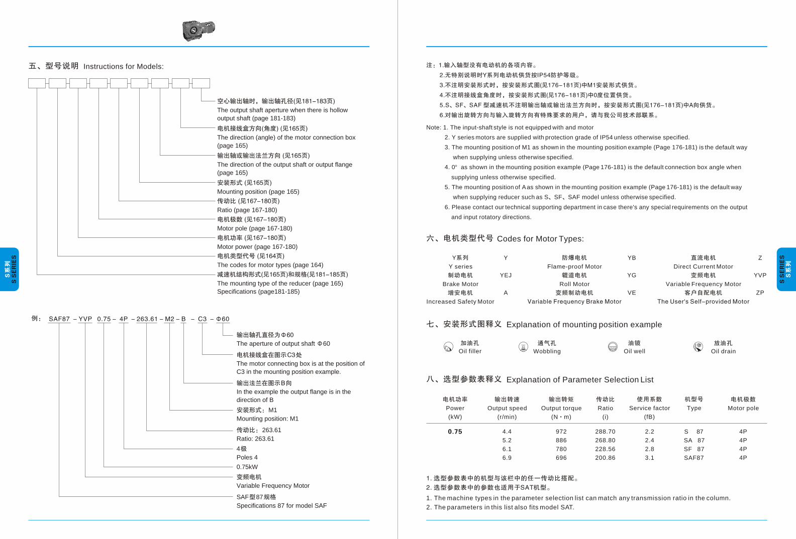
Instructions for Models:
The output shaft aperture when there is hollow
output shaft (page 181-183)
The direction (angle) of the motor connection box
(page 165)
The direction of the output shaft or output flange
(page 165)
Mounting position (page 165)
Ratio (page 167-180)
Motor pole (page 167-180)
Motor power (page 167-180)
The codes for motor types (page 164)
The mounting type of the reducer (page 165)
Specifications (page181-185)
Note: 1. The input-shaft style is not equipped with and motor
2. Y series motors are supplied with protection grade of IP54 unless otherwise specified.
3. The mounting position of M1 as shown in the mounting position example (Page 176-181) is the default way
when supplying unless otherwise specified.
4. 0 as shown in the mounting position example (Page 176-181) is the default connection box angle when
supplying unless otherwise specified.
5. The mounting position of A as shown in the mounting position example (Page 176-181) is the default way
when supplying reducer such as S SF SAF model unless otherwise specified.
6. Please contact our technical supporting department in case there's any special requirements on the output
and input rotatory directions.
Wobbling Oil drainOil filler
Y
Y series
Brake Motor
Increased Safety Motor
Codes for Motor Types:
Y
YEJ
A
Flame-proof Motor
Roll Motor
YB
YG
VE
Direct Current Motor
Variable Frequency Motor
Z
YVP
ZP
Explanation of mounting position example
Oil well
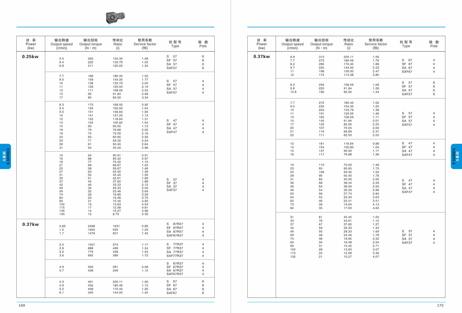
Explanation of Parameter Selection List
Power
(kW)
Output speed
(r/min)
Output torque
(N m)
Ratio
(i)
Service factor
(fB)
Type Motor pole
4.4
5.2
6.1
6.9
972
886
780
696
288.70
268.80
228.56
200.86
2.2
2.4
2.8
3.1
S 87
SA 87
SF 87
SAF87
4P
4P
4P
4P
1. The machine types in the parameter selection list can match any transmission ratio in the column.
2. The parameters in this list also fits model SAT.
The aperture of output shaft 60
The motor connecting box is at the position of
C3 in the mounting position example.
In the example the output flange is in the
direction of B
M1
Mounting position: M1
263.61
Ratio: 263.61
4
Poles 4
0.75kW
Variable Frequency Motor
SAF 87
Specifications 87 for model SAF

AB
AB
Weight(kg)
Type
Mounting position:
Position of the motor thermal box:
Gear unit type
Structure
Gear unit type
Input power rating and permissible torque
Lubrication table
The weights are mean values, only for reference.
Gear unit type
Gear unit type
Fill quantity in liters
Fill quantity in liters
Fill quantity in liters
S... SF SAF...
SAT...
Reducer weight

Output speed(r/min)
Ratio(i)
Service factor(fB)
Type
Pole
Output torque(N m)
Output speed(r/min)
Ratio(i)
Service factor(fB)
Type
Pole
Output torque(N m)
Output speed(r/min)
Ratio(i)
Service factor(fB)
Type
Pole
Output torque(N m)
170169
Output speed(r/min)
Ratio(i)
Service factor(fB)
Type
Pole
Output torque(N m)

Output speed(r/min)
Ratio(i)
Service factor(fB)
Type
Pole
Output torque(N m)
Output speed(r/min)
Ratio(i)
Service factor(fB)
Type
Pole
Output torque(N m)

Output speed(r/min)
Ratio(i)
Service factor(fB)
Type
Pole
Output torque(N m)
Output speed(r/min)
Ratio(i)
Service factor(fB)
Type
Pole
Output torque(N m)

Output speed(r/min)
Ratio(i)
Service factor(fB)
Type
Pole
Output torque(N m)
Output speed(r/min)
Ratio(i)
Service factor(fB)
Type
Pole
Output torque(N m)

Output speed(r/min)
Ratio(i)
Service factor(fB)
Type
Pole
Output torque(N m)
Output speed(r/min)
Ratio(i)
Service factor(fB)
Type
Pole
Output torque(N m)

Output speed(r/min)
Ratio(i)
Service factor(fB)
Type
Pole
Output torque(N m)
Output speed(r/min)
Ratio(i)
Service factor(fB)
Type
Pole
Output torque(N m)

L3L1
L0
h2
A0
1a
2
H1
a1
A0
A
g1
W W
l
H2
H0
h18 do
B0
B
A1
S
V1 V2
A6 A5
b
d
c
W1W1
M1
L
d1
b1
c1
W2 W1
R
M
L
L3L1
L0
H0
D
g1
H2
H2 H
1D1
D1
B
S..
SA..
M6
890
754-90
SA37SA47~97 D D1 L M SAZ..( 182 )
Type
Shaft dimensions Overall dimensions
Type
Shaft dimensions Overall dimensions
Type
Shaft dimensions
Overall dimensions
Type
Overall dimensions
For the diameters of D D1 L M for SA47~97please refer to SAZ..(see page 182)
The diameters of hollow shaft have two values in some types, please indicate in orders.
Note: see the remaining size SA (see 181)

Type
Shaft dimensions Overall dimensions
Type
Shaft dimensionsOverall dimensions
Motor norm
Type
TypeMotor norm
Type
Note: For other values please refer to the corresponding type ( see page 181-183 ).
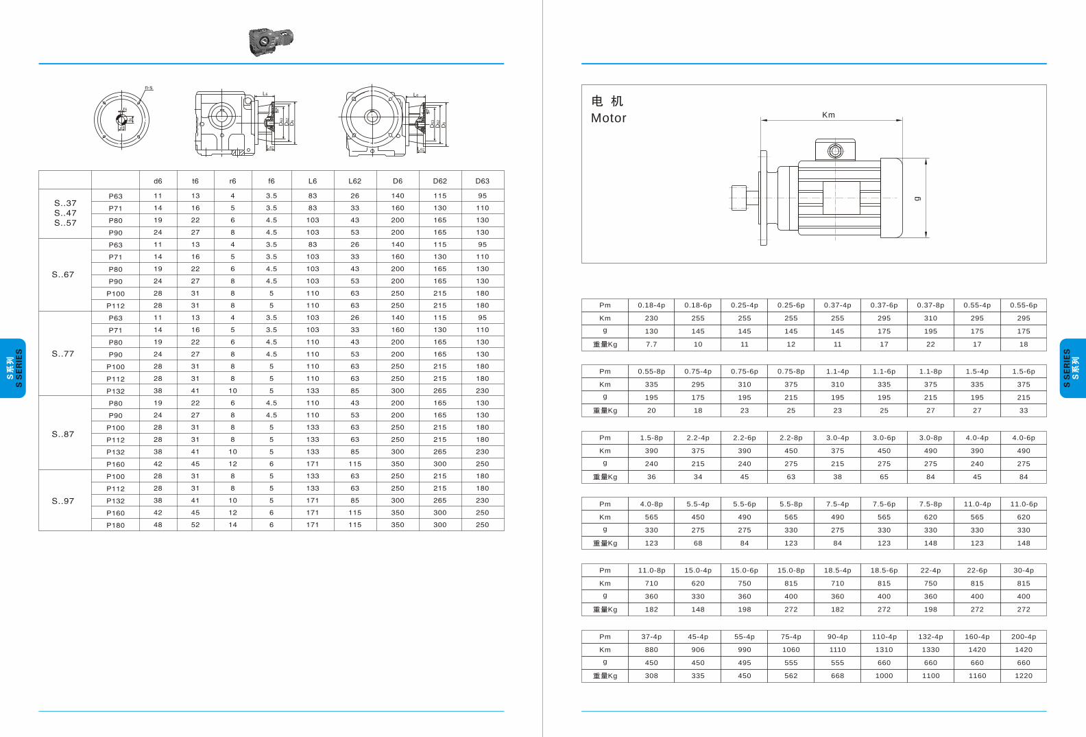
d
n-s
r6
t66
L6
f6
D6
3
D6
2
D6
L62
L6
f6
D6
3
D6
2
D6
L62
Motor Km
g
Pm
Km
g
Kg
0.18-4p
230
130
7.7
0.18-6p
255
145
10
0.25-4p
255
145
11
0.25-6p
255
145
12
0.37-4p
255
145
11
0.37-6p
295
175
17
0.37-8p
310
195
22
0.55-4p
295
175
17
0.55-6p
295
175
18
Pm
Km
g
Kg
0.55-8p
335
195
20
0.75-4p
295
175
18
0.75-6p
310
195
23
0.75-8p
375
215
25
1.1-4p
310
195
23
1.1-6p
335
195
25
1.1-8p
375
215
27
1.5-4p
335
195
27
1.5-6p
375
215
33
Pm
Km
g
Kg
1.5-8p
390
240
36
2.2-4p
375
215
34
2.2-6p
390
240
45
2.2-8p
450
275
63
3.0-4p
375
215
38
3.0-6p
450
275
65
3.0-8p
490
275
84
4.0-4p
390
240
45
4.0-6p
490
275
84
Pm
Km
g
Kg
4.0-8p
565
330
123
5.5-4p
450
275
68
5.5-6p
490
275
84
5.5-8p
565
330
123
7.5-4p
490
275
84
7.5-6p
565
330
123
7.5-8p
620
330
148
11.0-4p
565
330
123
11.0-6p
620
330
148
Pm
Km
g
Kg
11.0-8p
710
360
182
Pm
Km
g
Kg
37-4p
880
450
308
15.0-4p
620
330
148
15.0-6p
750
360
198
15.0-8p
815
400
272
18.5-4p
710
360
182
18.5-6p
815
400
272
22-4p
750
360
198
22-6p
815
400
272
30-4p
815
400
272
45-4p
906
450
335
55-4p
990
495
450
75-4p
1060
555
562
90-4p
1110
555
668
110-4p
1310
660
1000
132-4p
1330
660
1100
160-4p
1420
660
1160
200-4p
1420
660
1220