
Simulation for Wind Turbine Generators—With FAST and MATLAB ...
1
Abstract—This paper presents a summary of the most im-
portant characteristics of wind turbine generators applied in modern wind power plants. Various wind turbine generator designs, based on classification by machine type and speed control capabilities, are discussed along with their operational characteristics, voltage, reactive power, or power factor con-trol capabilities, voltage ride-through characteristics, behavior during short circuits, and reactive power capabilities.
Index Terms— Wind turbine generator, voltage ride-through, wind power plants.
I. INTRODUCTION
odern wind power plants (WPPs), comprised of a large number of wind turbine generators (WTGs), a
collector system, collector and/or interconnect substation utilize machines that are designed to optimize the genera-tion of power using the energy in the wind. WTGs have developed from small machines with output power ratings on the order of kilowatts to several megawatts, and from machines with limited speed control and other capabilities to machines with variable speed control capabilities over a wide speed range and sophisticated control capabilities using modern power electronics [1]. The application of WTGs in modern WPPs requires an understanding of a number of different aspects related to the design and capabilities of the machines involved. This paper, authored by members of the Wind Plant Collector Design Working Group of the IEEE, is intended to provide insight into the various wind turbine generator designs, based on classification by machine type and speed control capabilities, along with their operational characteristics, voltage, reactive power, or power factor control capabili-ties, voltage ride-through characteristics, behavior during short circuits, and reactive power capabilities.
II. TURBINE CHARACTERISTICS
The principle of wind turbine operation is based on two well-known processes. The first one involves the conver-sion of kinetic energy of moving air into mechanical ener-
gy. This is accomplished by using aerodynamic rotor blades and a variety of methodologies for mechanical pow-er control. The second process is the electro-mechanical energy conversion through a generator that is transmitted to the electrical grid.
Wind turbines can be classified by their mechanical power control, and further divided by their speed control. All turbine blades convert the motion of air across the air-foils to torque, and then regulate that torque in an attempt to capture as much energy as possible, yet prevent damage. At the top level turbines can be classified as either stall regulated (with active stall as an improvement) or pitch regulated.
Stall regulation is achieved by shaping the turbine blades such that the airfoil generates less aerodynamic force at high wind speed, eventually stalling, thus reducing the turbine’s torque—this is a simple, inexpensive and ro-bust mechanical system. Pitch regulation, on the other hand, is achieved through the use of pitching devices in the turbine hub, which twist the blades around their own axes. As the wind speed changes, the blade quickly pitches to the optimum angle to control torque in order to capture the maximum energy or self-protect, as needed. Some turbines now are able to pitch each blade independently to achieve more balanced torques on the rotor shaft given wind speed differences at the top and bottom of the blade arcs.
Beyond mechanical power regulation, turbines are fur-ther divided into fixed speed (Type 1), limited variable speed (Type 2), or variable speed with either partial (Type 3) or full (Type 4) power electronic conversion. The dif-ferent speed control types are implemented via different rotating AC machines and the use of power electronics. There is one other machine type that will be referred to as Type 5 in which a mechanical torque converter between the rotor’s low-speed shaft and the generator’s high-speed shaft controls the generator speed to the electrical syn-chronous speed. This type of machine then uses a syn-chronous machine directly connected to the medium vol-tage grid.
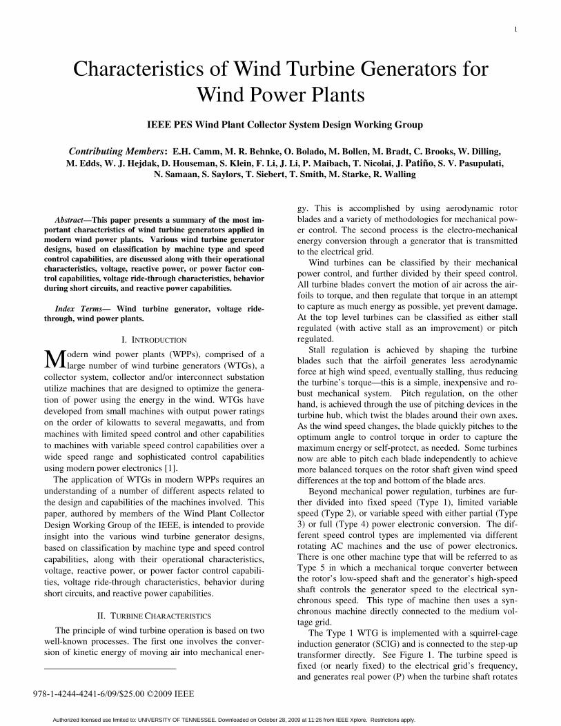
The Type 1 WTG is implemented with a squirrel-cage induction generator (SCIG) and is connected to the step-up transformer directly. See Figure 1. The turbine speed is fixed (or nearly fixed) to the electrical grid’s frequency, and generates real power (P) when the turbine shaft rotates
IEEE PES Wind Plant Collector System Design Working Group
Contributing Members: E.H. Camm, M. R. Behnke, O. Bolado, M. Bollen, M. Bradt, C. Brooks, W. Dilling, M. Edds, W. J. Hejdak, D. Houseman, S. Klein, F. Li, J. Li, P. Maibach, T. Nicolai, J. Patiño, S. V. Pasupulati,
N. Samaan, S. Saylors, T. Siebert, T. Smith, M. Starke, R. Walling
Characteristics of Wind Turbine Generators for Wind Power Plants
M
978-1-4244-4241-6/09/$25.00 ©2009 IEEE
Authorized licensed use limited to: UNIVERSITY OF TENNESSEE. Downloaded on October 28, 2009 at 11:26 from IEEE Xplore. Restrictions apply.
2
faster than the electrical grid frequency creating a negative slip (positive slip and power is motoring convention).
GearBox
IGCollectorFeeder
Soft Starter Cap Bank
GearBox
IGCollectorFeeder
GearBox
IGIGCollectorFeeder
Soft Starter Cap BankSoft StarterSoft Starter Cap BankCap Bank
Figure 1: Typical Configuration of a Type 1 WTG
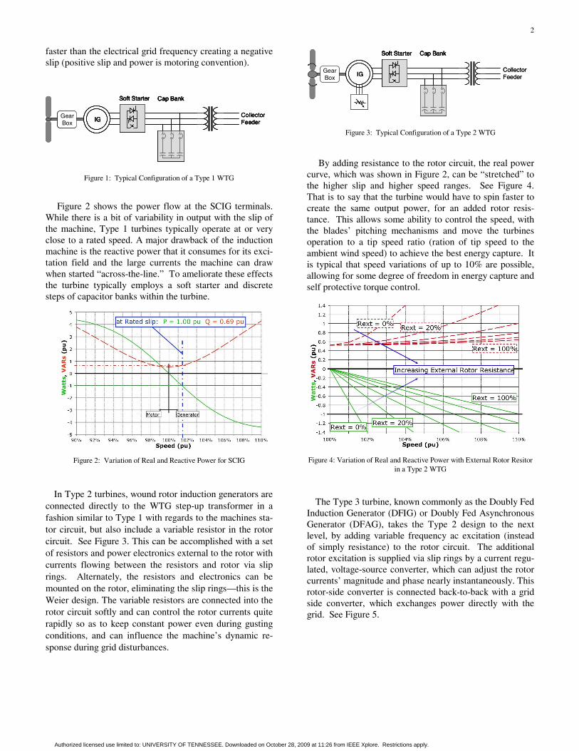
Figure 2 shows the power flow at the SCIG terminals. While there is a bit of variability in output with the slip of the machine, Type 1 turbines typically operate at or very close to a rated speed. A major drawback of the induction machine is the reactive power that it consumes for its exci-tation field and the large currents the machine can draw when started “across-the-line.” To ameliorate these effects the turbine typically employs a soft starter and discrete steps of capacitor banks within the turbine.
Figure 2: Variation of Real and Reactive Power for SCIG
In Type 2 turbines, wound rotor induction generators are connected directly to the WTG step-up transformer in a fashion similar to Type 1 with regards to the machines sta-tor circuit, but also include a variable resistor in the rotor circuit. See Figure 3. This can be accomplished with a set of resistors and power electronics external to the rotor with currents flowing between the resistors and rotor via slip rings. Alternately, the resistors and electronics can be mounted on the rotor, eliminating the slip rings—this is the Weier design. The variable resistors are connected into the rotor circuit softly and can control the rotor currents quite rapidly so as to keep constant power even during gusting conditions, and can influence the machine’s dynamic re-sponse during grid disturbances.
GearBox
IGCollectorFeeder
Soft Starter Cap Bank
GearBox
IGIGCollectorFeeder
Soft Starter Cap BankSoft StarterSoft Starter Cap BankCap Bank
Figure 3: Typical Configuration of a Type 2 WTG
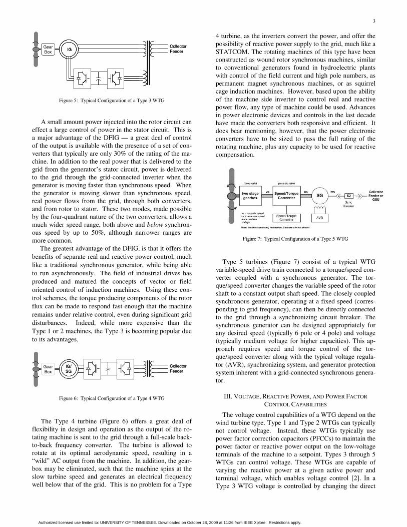
By adding resistance to the rotor circuit, the real power
curve, which was shown in Figure 2, can be “stretched” to the higher slip and higher speed ranges. See Figure 4. That is to say that the turbine would have to spin faster to create the same output power, for an added rotor resis-tance. This allows some ability to control the speed, with the blades’ pitching mechanisms and move the turbines operation to a tip speed ratio (ration of tip speed to the ambient wind speed) to achieve the best energy capture. It is typical that speed variations of up to 10% are possible, allowing for some degree of freedom in energy capture and self protective torque control.
Figure 4: Variation of Real and Reactive Power with External Rotor Resitor in a Type 2 WTG
The Type 3 turbine, known commonly as the Doubly Fed Induction Generator (DFIG) or Doubly Fed Asynchronous Generator (DFAG), takes the Type 2 design to the next level, by adding variable frequency ac excitation (instead of simply resistance) to the rotor circuit. The additional rotor excitation is supplied via slip rings by a current regu-lated, voltage-source converter, which can adjust the rotor currents’ magnitude and phase nearly instantaneously. This rotor-side converter is connected back-to-back with a grid side converter, which exchanges power directly with the grid. See Figure 5.
Authorized licensed use limited to: UNIVERSITY OF TENNESSEE. Downloaded on October 28, 2009 at 11:26 from IEEE Xplore. Restrictions apply.
3
GearBox
CollectorFeederIG
GearBox
CollectorFeederIGIG
Figure 5: Typical Configuration of a Type 3 WTG
A small amount power injected into the rotor circuit can
effect a large control of power in the stator circuit. This is a major advantage of the DFIG — a great deal of control of the output is available with the presence of a set of con-verters that typically are only 30% of the rating of the ma-chine. In addition to the real power that is delivered to the grid from the generator’s stator circuit, power is delivered to the grid through the grid-connected inverter when the generator is moving faster than synchronous speed. When the generator is moving slower than synchronous speed, real power flows from the grid, through both converters, and from rotor to stator. These two modes, made possible by the four-quadrant nature of the two converters, allows a much wider speed range, both above and below synchron-ous speed by up to 50%, although narrower ranges are more common.
The greatest advantage of the DFIG, is that it offers the benefits of separate real and reactive power control, much like a traditional synchronous generator, while being able to run asynchronously. The field of industrial drives has produced and matured the concepts of vector or field oriented control of induction machines. Using these con-trol schemes, the torque producing components of the rotor flux can be made to respond fast enough that the machine remains under relative control, even during significant grid disturbances. Indeed, while more expensive than the Type 1 or 2 machines, the Type 3 is becoming popular due to its advantages.
GearBox
IG/SG
CollectorFeeder
GearBox
IG/SG
CollectorFeeder
Figure 6: Typical Configuration of a Type 4 WTG
The Type 4 turbine (Figure 6) offers a great deal of
flexibility in design and operation as the output of the ro-tating machine is sent to the grid through a full-scale back-to-back frequency converter. The turbine is allowed to rotate at its optimal aerodynamic speed, resulting in a “wild” AC output from the machine. In addition, the gear-box may be eliminated, such that the machine spins at the slow turbine speed and generates an electrical frequency well below that of the grid. This is no problem for a Type
4 turbine, as the inverters convert the power, and offer the possibility of reactive power supply to the grid, much like a STATCOM. The rotating machines of this type have been constructed as wound rotor synchronous machines, similar to conventional generators found in hydroelectric plants with control of the field current and high pole numbers, as permanent magnet synchronous machines, or as squirrel cage induction machines. However, based upon the ability of the machine side inverter to control real and reactive power flow, any type of machine could be used. Advances in power electronic devices and controls in the last decade have made the converters both responsive and efficient. It does bear mentioning, however, that the power electronic converters have to be sized to pass the full rating of the rotating machine, plus any capacity to be used for reactive compensation.
Figure 7: Typical Configuration of a Type 5 WTG
Type 5 turbines (Figure 7) consist of a typical WTG variable-speed drive train connected to a torque/speed con-verter coupled with a synchronous generator. The tor-que/speed converter changes the variable speed of the rotor shaft to a constant output shaft speed. The closely coupled synchronous generator, operating at a fixed speed (corres-ponding to grid frequency), can then be directly connected to the grid through a synchronizing circuit breaker. The synchronous generator can be designed appropriately for any desired speed (typically 6 pole or 4 pole) and voltage (typically medium voltage for higher capacities). This ap-proach requires speed and torque control of the tor-que/speed converter along with the typical voltage regula-tor (AVR), synchronizing system, and generator protection system inherent with a grid-connected synchronous genera-tor.
III. VOLTAGE, REACTIVE POWER, AND POWER FACTOR
CONTROL CAPABILITIES
The voltage control capabilities of a WTG depend on the wind turbine type. Type 1 and Type 2 WTGs can typically not control voltage. Instead, these WTGs typically use power factor correction capacitors (PFCCs) to maintain the power factor or reactive power output on the low-voltage terminals of the machine to a setpoint. Types 3 through 5 WTGs can control voltage. These WTGs are capable of varying the reactive power at a given active power and terminal voltage, which enables voltage control [2]. In a Type 3 WTG voltage is controlled by changing the direct
Authorized licensed use limited to: UNIVERSITY OF TENNESSEE. Downloaded on October 28, 2009 at 11:26 from IEEE Xplore. Restrictions apply.
4
component of the rotor current (this is the component of the current that is in-line with the stator flux). In a Type 4 WTG voltage control is achieved by varying the quadrature (reactive) component of current at the grid-side converter. To allow voltage control capability, the grid-side converter must be rated above the rated MW of the machine. Since a synchronous generator is used in a Type 5 WTG, an auto-matic voltage regulator (AVR) is typically needed. Modern AVRs can be programmed to control reactive power, pow-er factor and voltage.
The voltage control capabilities of individual WTGs are typically used to control the voltage at the collector bus or on the high side of the main power transformer. Usually a centralized wind farm controller will manage the control of the voltage through communication with the individual WTGs. A future companion Working Group paper is planned to discuss the WPP SCADA and control capabili-ties.
IV. REACTIVE POWER CAPABILITIES
The reactive power capabilities of modern WTGs are significant as most grid codes require the WPP to have reactive power capability at the point of interconnect over a specified power factor range, for example 0.95 leading (inductive) to 0.95 lagging (capacitive). Typical intercon-nect requirements related to total WPP reactive power ca-pabilities are discussed in [3]. As stated earlier, Type 1 and Type 2 WTGs typically use PFCCs to maintain the power factor or reactive power of the machine to a specified setpoint. The PFCCs may be sized to maintain a slightly leading (inductive) power fac-tor of around 0.98 at rated power output. This is often referred to as no-load compensation. With full-load com-pensation, the PFCCs are sized to maintain unity power factor or, in some cases, a slightly lagging (capacitive) power factor at the machine’s rated power output. The PFCCs typically consists of multiple stages of capacitors switched with a low-voltage AC contactor. Type 3 (DFIG) WTGs typically have a reactive power capability corresponding to a power factor of 0.95 lagging (capacitive) to 0.90 leading (inductive) at the terminals of the machines. Options for these machines include an ex-panded reactive power capability of 0.90 lagging to 0.90 leading. Some Type 3 WTGs can deliver reactive power even when the turbine is not operating mechanically, while no real power is generated.
As previously stated, Type 4 WTGs can vary the grid-side converter current, allowing control of the effective power factor of the machines over a wide range. Reactive power limit curves for different terminal voltage levels are typically provided. Some Type 4 WTGs can deliver reac-tive power even when the turbine is not operating mechan-ically, while no real power is generated.
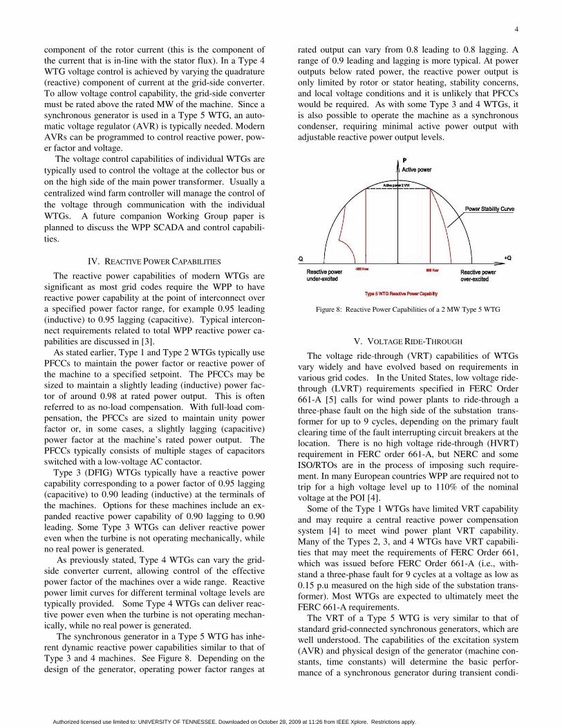
The synchronous generator in a Type 5 WTG has inhe-rent dynamic reactive power capabilities similar to that of Type 3 and 4 machines. See Figure 8. Depending on the design of the generator, operating power factor ranges at
rated output can vary from 0.8 leading to 0.8 lagging. A range of 0.9 leading and lagging is more typical. At power outputs below rated power, the reactive power output is only limited by rotor or stator heating, stability concerns, and local voltage conditions and it is unlikely that PFCCs would be required. As with some Type 3 and 4 WTGs, it is also possible to operate the machine as a synchronous condenser, requiring minimal active power output with adjustable reactive power output levels.
Figure 8: Reactive Power Capabilities of a 2 MW Type 5 WTG
V. VOLTAGE RIDE-THROUGH
The voltage ride-through (VRT) capabilities of WTGs vary widely and have evolved based on requirements in various grid codes. In the United States, low voltage ride-through (LVRT) requirements specified in FERC Order 661-A [5] calls for wind power plants to ride-through a three-phase fault on the high side of the substation trans-former for up to 9 cycles, depending on the primary fault clearing time of the fault interrupting circuit breakers at the location. There is no high voltage ride-through (HVRT) requirement in FERC order 661-A, but NERC and some ISO/RTOs are in the process of imposing such require-ment. In many European countries WPP are required not to trip for a high voltage level up to 110% of the nominal voltage at the POI [4]. Some of the Type 1 WTGs have limited VRT capability and may require a central reactive power compensation system [4] to meet wind power plant VRT capability. Many of the Types 2, 3, and 4 WTGs have VRT capabili-ties that may meet the requirements of FERC Order 661, which was issued before FERC Order 661-A (i.e., with-stand a three-phase fault for 9 cycles at a voltage as low as 0.15 p.u measured on the high side of the substation trans-former). Most WTGs are expected to ultimately meet the FERC 661-A requirements. The VRT of a Type 5 WTG is very similar to that of standard grid-connected synchronous generators, which are well understood. The capabilities of the excitation system (AVR) and physical design of the generator (machine con-stants, time constants) will determine the basic perfor-mance of a synchronous generator during transient condi-
Authorized licensed use limited to: UNIVERSITY OF TENNESSEE. Downloaded on October 28, 2009 at 11:26 from IEEE Xplore. Restrictions apply.
5
tions. In order to meet utility VRT requirements, the set-tings and operation of the turbine control system, excita-tion system and protection systems must be generally coordinated and then fine-tuned for a specific site.
VI. WTG BEHAVIOR DURING GRID SHORT CIRCUITS
The response of WTGs to short circuits on the grid depends largely on the type of WTG. While the response of Type 1 and Type 2 WTGs are essentially similar to that of large induction machines used in industrial applications, the response of Type 3, 4, and 5 WTGs is dictated by the WTG controls. In short circuit calculations, a Type 1 WTG can be represented as a voltage source in series with the direct axis sub-transient inductance dX ′′ . This practice
is used to consider the maximum short-circuit contribution from the induction generator as it determines the symme-trical current magnitude during the first few cycles after the fault. A Type 1 WTG can contribute short circuit cur-rent up to the value of its locked rotor current which is usually on the order of 5 to 6 p.u [6].
Type 2 WTGs employing limited speed control via con-trolled external rotor resistance are fundamentally induc-tion generators. If, during the fault, the external resistance control were to result in short-circuiting of the generator rotor, the short-circuit behavior would be similar to Type 1. On the other hand, if the control action at or shortly after fault inception were to result in insertion of the full exter-nal resistance, the equivalent voltage source-behind-Thevenin impedance representation for the WTG should be modified to include this significant resistance value in series with the equivalent turbine inductance.
Other wind turbine topologies employ some type of power electronic control. Consequently, the behavior dur-ing short-circuit conditions cannot be ascertained directly from the physical structure of the electrical generator. Algorithms which control the power electronic switches can have significant influence on the short-circuit currents contributed by the turbine, and the details of these control-lers are generally held closely by the turbine manufactur-ers.
For Type 3 WTGs (DFIG), if during the fault, the rotor power controller remains active, the machine stator cur-rents would be limited between 1.1 to 2.5 p.u. of the ma-chine rated current. Under conditions where protective functions act to “crowbar” the rotor circuit, the short-circuit behavior defaults to 5 to 6 p.u. in the case of a fault applied directly to the WTG terminals. [7] In turbines employing full-rated power converters as the interface to the grid (Type 4), currents during network faults will be limited to slightly above rated current. This limitation is affected by the power converter control, and is generally necessary to protect the power semiconductor switches. Type 5 WTGs exhibit typical synchronous generator behavior during grid short circuits. Generator contribution to grid faults can be calculated from the machine constants,
obtainable from the generator manufacturer. Fault current contribution for line to ground faults will depend on the type of generator grounding used. Typical generator fault current contribution can range from 4 to more times rated current for close-in bolted three-phase faults. Fault current contribution for single-line to ground faults can range from near zero amps (ungrounded neutral) to more than the three-phase bolted level (depending on the zero sequence impedance of solidly grounded generators.) A joint Working Group sponsored by the Power Systems Relaying Committee (PSRC) and the T&D Committee on short-circuit contributions from WTGs is currently discuss-ing this topic. It is expected that more specific guidelines on considerations in determining short-circuit contributions from different types of WTGs will be forthcoming.
VII. REFERENCES [1] Robert Zavadil, Nicholas Miller, Abraham Ellis, and Eduard Muljadi,
“Making Connections [Wind Generation Facilities],” IEEE Power & Energy Magazine, vol. 3, no. 6, pp. 26-37, Nov.-Dec. 2005.
[2] W.L. Kling, J.G. Slootweg, “Wind Turbines as Power Plants” IEEE/Cigré Workshop on Wind Power and the Impacts on Power Sys-tems, June 2002, Oslo, Norway.
[3] Wind Plant Collector System Design Working Group, “Wind Power Plant Collector System Design Considerations,” in Proc. 2009 IEEE Power and Energy Society General Meeting, Calgary, Canada, July 2009.
[4] Wind Plant Collector SystemDesign Working Group, “Reactive Power Compensation for Wind Power Plants,” in Proc. 2009 IEEE Power and Energy Society General Meeting, Calgary, Canada, July 2009.
[5] FERC Order no. 661-A, "Interconnection for Wind Energy,” Docket No. RM05-4-001, December 2005.
[6] Nader Samaan, Robert Zavadil, J. Charles Smith and Jose Conto, “Modeling of Wind Power Plants for Short Circuit Analysis in the Transmission Network,” in Proc. of IEEE/PES Transmission and Dis-tribution Conference, Chicago, USA, April 2008.
[7] J. Morreu, S.W.H. de Haan, “Ridethrough of Wind Turbines with Doubly-Fed Induction Generator During a Voltage Dip,” IEEE Trans-actions on Energy Conversion, vol. 20, no. 2, June 2005
[8] Ackermann, Thomas, ed. Wind Power in Power Systems. West Sus-sex, UK: John Wiley & Sons, 2005. ISBN 13: 978-0-470-85508-9
[9] Hau, Erich. Wind Turbines: Fundamentals, Technologies, Applica-tion, Economics, 2nd Edition. Trans. Horst von Renouard. Sidcup, Kent, UK: Springer, 2006. ISBN 13: 978-3-540-24240-6
Authorized licensed use limited to: UNIVERSITY OF TENNESSEE. Downloaded on October 28, 2009 at 11:26 from IEEE Xplore. Restrictions apply.