CHARACTERISTICS OF MULTI-MODE SENSOR FOR PARTIAL...
31
CHARACTERISTICS OF MULTI-MODE SENSOR FOR PARTIAL DISCHARGE SIGNAL MONITORING IN OIL INSULATION OSAMAH SALAM LAFTA UNIVERSITI TEKNOLOGI MALAYSIA
-
Upload
hoangthien -
Category
Documents
-
view
213 -
download
0
Transcript of CHARACTERISTICS OF MULTI-MODE SENSOR FOR PARTIAL...

1
CHARACTERISTICS OF MULTI-MODE SENSOR FOR PARTIAL
DISCHARGE SIGNAL MONITORING IN OIL INSULATION
OSAMAH SALAM LAFTA
UNIVERSITI TEKNOLOGI MALAYSIA

4
CHARACTERISTICS OF MULTI-MODE SENSOR FOR PARTIAL DISCHARGE
SIGNAL MONITORING IN OIL INSULATION
OSAMAH SALAM LAFTA
A project report submitted in partial fulfilment of the
requirements for the award of the degree of
Master of Engineering (Electrical-Power)
Faculty of Electrical Engineering
Universiti Teknologi Malaysia
JUNE 2014

iii
This thesis dedicated to:-
My mother who has been a source of warm-heartedness, love
and inspiration to me throughout my life.
My father who has been a constant source of support and
encouragement during the challenges of graduate
school and life.
My brothers and sister and for my future wife , for their endless
love ,supports and encouragement
I am truly thankful for having all of you in my life
God bless you all

iv
ACKNOWLEDGEMENT
Praise be to God, who sent his messenger with guidance and the
religion of truth to proclaim it over all religions, and make it a good example for
those who had hope for Allah, then praise be to God Almighty whom through his
will and his grace that supported the completion of this work.
I express great gratitude and thanks to my supervisor, DR. Mohd Muhridza
Bin Yaacobb for supporting me throughout the duration of the research in spite of the
difficulties. My sincere appreciation and respect to him and I pray to God for him to
be richly rewarded.
As well I thank the members of my family who were the best help and
support for me throughout the years of study and I ask Allah to reward my parents
who gave me everything generously and without hesitation. I wish to express my
thanks to them for being tolerant with me in times of hardship. My prayers to God to
reward them with the best.
OSAMAH

v
ABSTRACT
Partial Discharge (PD) is a term used to describe electrical discharge activity
which is normally accompanied by sparks. PD can occur when electric field
difference across the void exceeds the minimum breakdown field strength.
Therefore, PD measurement and diagnosis is an important nondestructive technique
for assessing the quality and integrity of high voltage transformer. In practice, PD
measurements suffer from noise interference due to low sensitivity of available
sensors. Noisy signal at the output of the sensors cause inaccuracy in the detection
of PD. In this work a multimode optical fiber sensor would be used to detect PD in
transformer because it has the advantages such as: small size and weight, enormous
potential bandwidth, immunity to interference and crosstalk, and compare it with
electrical(capacitive) sensor. PD was detected at atmospheric pressure in voltage
range (0-20 kV), the output from these two detection processes and the source wave
form fed into separate channels of the multichannel digital oscilloscope. The gained
data has been analyzed in time and frequency domain by using (OrginPro8) software.
These results show that the appearance of PD caused a ripple in the shape of source
wave form and it is being more clear in high voltage rang where in time domain
these results show that signal generated by PD contains a sinusoidal pulses. The
shapes and peaks of the signal output of both sensors follow the same oscillatory
pattern at the same time with the ripple in the source wave form. Although these
shapes and peaks of the signal output of both sensors are not much clear in voltage
range below (20 KVp-p) but in voltage range above (20 KVp-p) the optical sensor
shows good sensitivity where it shows up clear peaks and more than the capacitive
sensor and this conclusion approved by the Frequency Domain Analysis the Fast
Fourier Transform (FFT) where optical shows good resolution in range of voltage
above (20 KVp-p).

vi
ABSTRAK
Nyahcas separa (PD) adalah istilah yang digunakan untuk menggambarkan
aktiviti pelepasan elektrik yang biasanya diiringi oleh percikan api. PD boleh berlaku
apabila perbezaan medan elektrik merentasi kekosongan melebihi kerosakan minimum
kekuatan medan. Oleh itu, pengukuran dan diagnosis PD adalah satu teknik tanpa
musnah yang penting untuk menilai kualiti dan integriti transformer voltan tinggi. Pada
praktiknya, pengukuran PD mengalami gangguan hingar kerana sensitiviti rendah sensor
yang ada. Syarat hingar pada output sensor menyebabkan ketidaktepatan dalam
pengesanan PD. Dalam kajian ini, sensor gentian optik multimod digunakan untuk
mengesan PD dalam transformer kerana mempunyai kelebihan seperti kecil dan ringan,
potensi jalur lebar yang besar, rintang/imuniti terhadap gangguan dan cakap silang
(crosstalk) berbanding sensor elektrik (kapasitif). PD dikesan pada tekanan atmosfera
dalam julat voltan (0-20 kV), output daripada kedua-dua proses pengesanan dan bentuk
gelombang sumber disuap ke dalam saluran berasingan osiloskop digital berbilang
saluran. Data yang diperolehi dianalisis dalam domain masa dan frekuensi
menggunakan perisian (OrginPro8). Keputusan ini menunjukkan bahawa kemunculan
PD menyebabkan riak dalam bentuk gelombang sumber dan ianya menjadi lebih jelas
dalam gegelang voltan tinggi yang mana dalam domain masa keputusan ini
menunjukkan bahawa isyarat yang dihasilkan oleh PD mengandungi denyutan sinus.
Bentuk dan puncak output isyarat kedua-dua sensor mengikut corak ayunan yang sama
pada masa yang sama dengan riak dalam bentuk gelombang sumber. Walaupun bentuk
dan puncak output isyarat kedua-dua sensor tidak banyak jelas dalam julat voltan bawah
(20kVp-p) tetapi dalam julat voltan di atas (20 KVP-p), sensor optik menunjukkan
sensitiviti yang baik yang mana ia menunjukkan puncak jelas dan lebih daripada sensor
kapasitif dan kesimpulan ini diluluskan oleh Kekerapan Analisis Domain Fourier pantas
(FFT) yang menunjukkan optik resolusi yang baik dalam julat voltan di atas (20 KVP-p).

vii
TABLE OF CONTENTS
CHAPTER TITLE PAGE
DECLARATION ii
DEDICATION iii
ACKNOWLEDGEMENT iv
ABSTRACT v
ABSTRAK vi
TABLE OF CONTENTS vii
LIST OF TABLES x
LIST OF FIGURES xi
LIST OF ABBREVIATIONS xv
LIST OF APPENDICES xvii
1 INTRODUCTION 1
1.1 Introduction of Research 1
1.2 Background of Research 5
1.3 Problem Statement 7
1.4 Objectives of Research 8
1.5 Scope of Research 9
1.6 Significance of the Study 9
2 LITERATURE REVIEW 11
2.1 Introduction 11
2.2 Types of Partial Discharges 12

viii
2.2.1 Internal Discharge 12
2.2.2 Surface Discharge 13
2.2.3 Corona Discharge 14
2.2.4 Electrical Treeing 14
2.2.5 Dielectric Barrier Discharge (DBD) 15
2.3 Partial Discharge Detection Methods 15
2.3.1 Electrical Detection Methods 17
2.3.1.1 Capacitive Sensor 18
2.3.1.2 Capacitive Coupling 19
2.3.1.3 Material of Capacitive
Sensor
20
2.3.2 Acoustic Detection 21
2.3.3 Chemical Detection 21
2.3.4 Optical Detection 22
2.3.4.1 Background about the
Optical Fiber
22
2.3.4.2 Optical Fiber Types 24
2.3.4.3 Principle of Detection 25
2.3.4.4 Optical Detection of PD in
Transformer Using Mach–
Zehnder Interferometers
26
2.3.4.5 Optical Detection of PD in
Transformer Using Fabry–
Perot Interferometric Sensor
27
2.3.5 Optical Sensor 28
2.3.5.1 Development of Optical
Sensor
31
3 METHODOLOGY 38
3.1 Introduction 38
3.2 Preparation of Sensors and the Equipment’s 39
3.2.1 Light Source 40
3.2.2 Photo Diode (BPX65) 40

ix
3.2.3 The Multimode Fiber Step-Index
(MMF-SI)
41
3.2.4 Capacitive Sensor 42
3.2.5 High Voltage Probe 43
3.26 Oscilloscope 44
3.3 Experimental Setup 44
3.4 Acquisition and Analysis the Data 46
3.5 Flow Chart of Methodology 48
4 RESULTS AND DISCUSSION 49
4.1 Introduction 49
4.2 Sensor Characteristic Results 49
4.2.1 Time Domain Analysis 50
4.2.2 Frequency Domain Analysis 55
5 CONCLUSION AND FUTURE WORK 60
5.1 Conclusion 60
5.2 Recommendations for Future Work 61
REFERENCES 62
Appendices A-D 66-73
x
LIST OF TABLES
TABLE NO TITLE PAGE
4.1 Resolution of the tow sensors at different voltage 58
xi
LIST OF FIGURES
FIGURE NO TITLE PAGE
2.1 Surface discharge, a) on the bushing surface close
to the transformer flange, b) on the end of outer
semiconductor in a cable termination Reference:
[7]
14
2.2 A schematic of PD measurement system [7] 16
2.3 Capacitive sensor 20
2.4 Fiber optic 22
2.5 Fiber layers 23
2.6 Optical Fiber Modes 24
2.7 Experimental set up for detection of PD generated
in laboratory condition using Mach–Zehnder
interferometers[20]
27
2.8 Illustration of principle of Fabry–Perot
interferometric sensor []
28

xii
2.9 (a) Optical fiber sensor. (b) Intrinsic multimode
optical fiber sensor. [33]
29
2.10 Block diagram of an all optical fiber acoustic
sensor
31
2.11 Optical fiber interferometric system and Output
signals
32
2.12 Setup of the optical measurement system 33
2.13 Response of the optical and piezo-electric sensors
to the shock pulse
33
2.14 A 66 KV hair-pin current transformer 33
2.15 PD signals occurring in a 66KV current
transformer detected by non-intrusive fibre sensor
34
2.16 Partial discharge signals from optical and
piezoelectric sensors. Piezo-electric signal has
already been amplified 10 times (x10) for a. better
vision
34
2.17 Experimental setup for PD detection 35
2.18 PD detection at the same distance between sound
source and sensors
35
2.19 Experimental setup of FO and PZT sensors dipped
in an oil tank
36
3.1 Overall process of project 39

xiii
3.2 Light source with spectral output 40
3.3 Photodiode (BPX65) with its relative spectral
sensitivity
41
3.4 The relationship between the attenuations and
wavelength
42
3.5 Capacitive Sensor 43
3.6 High voltage probe 43
3.7 Oscilloscope 44
3.8 Experimental setup 46
3.9 Actual experimental setup in the lab 46
3.10 Actual setup in the lab 46
4.1a Oscillograph for (5KVP-P) where channel 1 high-
voltage probe, channel 2 is the output of OFS., and
channel 3 is the output of capacitive sensor
50
4.1b Time domain analysis for (5kv p-p) after the
denoised
51
4.2a Oscillograph for (20 KVP-P) where channel 1
high-voltage probe, channel 2 is the output of
OFS., and channel 3 is the output of capacitive
sensor
51

xiv
4.2b Time domain analysis for (20 kv p-p) after the
denoised
52
4.3a Oscillograph for (35 KVP-P) where channel 1
high-voltage probe, channel 2 is the output of OFS
and channel 3 is the output of capacitive sensor
52
4.3b Time domain analysis for (35kv p-p) after the
denoised
53
4.4a Oscillograph for (37 KVP-P) where channel 1
high-voltage probe, channel 2 is the output of
OFS., and channel 3 is the output of capacitive
sensor
53
4.4b Time domain analysis for (37kv p-p) after the
denoised
54
4.5 (5KVp-p) FFT spectrum of output signal for (a)
FOS , (b) capacitive sensor
56
4.6 (20 KV p-p) FFT spectrum of output signal for (a)
FOS , (b) capacitive sensor
56
4.7 (35 KV p-p) FFT spectrum of output signal for (a)
FOS , (b) capacitive sensor
57
4.8 (37 KV p-p) FFT spectrum of output signal for (a)
FOS, (b) capacitive sensor
57
4.9 Resolution chart 59

xv
LIST OF ABBREVIATIONS
AC - Alternative voltage
AE - Acoustic emissions
Cm - Centimetre
dB - Decibel
DBD - Dielectric Barrier Discharge
DC - Direct current
EHV - Extra high-voltage
EMI - Electro-magnetic interference
F - Frequency
FFT - Fast Fourier transform
FOS - Fibre Optic Sensor
GHz - Giga hertz
GIS - Gas insulated switcher
HF - High frequency
HV - High Voltage
kHz - Kilo hertz
kV - kilo volt
LED - Light emit diode
LLD - Low Level Discriminator
M - Meter
MHz - Mega hertz
mm - Millimeter
MMF - Multimode fiber
mS - Milli second
mW - milli watt

xvi
Nm - Nanometer
Pc - Pico Column
PZT - Piezoelectric
PD - Partial discharge
SI - Step index
SNR - Signal to noise ratio
µm - Micro meter
UHF - Ultra high frequency
V - Voltage
VHF - Very High Frequency
-
xvii
LIST OF APPENDICES
APPENDIX TITLE PAGE
A Results of (10,15,25,30,) KV p-p after de-noise
66
B Results before the de-noise
69
C Oil characteristic 73
1
CHAPTER 1
INTRODUCTION
1.1 Introduction of Research
High voltage equipment’s are considered as one of the essential elements in
electrical network. Any failure in these equipment’s directly reduces network
reliability and increases maintenance costs. In a power system failure of major
elements can cause disruptions and result in very expensive losses. An on-line
continuous insulation monitoring diagnostic system helps prevent power
interruptions and costly damage caused by insulation failure. Most insulation
failures are caused by partial discharges (PD) that are localized electrical discharges
within a void of an insulation system. Although only a small amount of energy is
involved, the PD can cause the progressive deterioration of the insulation that may
lead to a disruptive breakdown [16]. Therefore, it is necessary to detect and
monitoring and assess the PD for high voltage equipment insulation. In such
applications, an understanding of PD mechanisms, characteristics and development
processes is important. The insulation system has high risk for dielectric stability
when PD occurs. Therefore, measurement of PD is important to prevent high-
voltage equipment from damage [17].
2
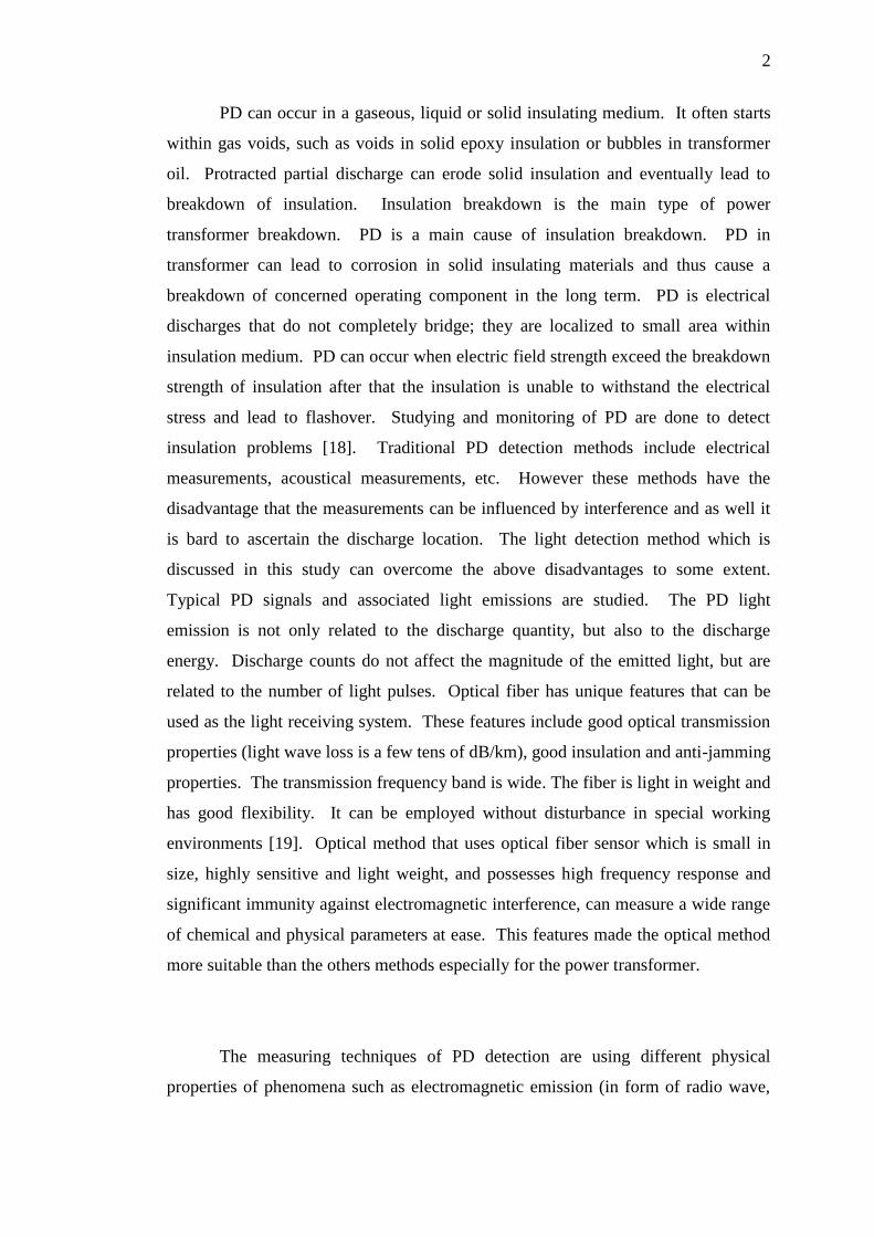
PD can occur in a gaseous, liquid or solid insulating medium. It often starts
within gas voids, such as voids in solid epoxy insulation or bubbles in transformer
oil. Protracted partial discharge can erode solid insulation and eventually lead to
breakdown of insulation. Insulation breakdown is the main type of power
transformer breakdown. PD is a main cause of insulation breakdown. PD in
transformer can lead to corrosion in solid insulating materials and thus cause a
breakdown of concerned operating component in the long term. PD is electrical
discharges that do not completely bridge; they are localized to small area within
insulation medium. PD can occur when electric field strength exceed the breakdown
strength of insulation after that the insulation is unable to withstand the electrical
stress and lead to flashover. Studying and monitoring of PD are done to detect
insulation problems [18]. Traditional PD detection methods include electrical
measurements, acoustical measurements, etc. However these methods have the
disadvantage that the measurements can be influenced by interference and as well it
is bard to ascertain the discharge location. The light detection method which is
discussed in this study can overcome the above disadvantages to some extent.
Typical PD signals and associated light emissions are studied. The PD light
emission is not only related to the discharge quantity, but also to the discharge
energy. Discharge counts do not affect the magnitude of the emitted light, but are
related to the number of light pulses. Optical fiber has unique features that can be
used as the light receiving system. These features include good optical transmission
properties (light wave loss is a few tens of dB/km), good insulation and anti-jamming
properties. The transmission frequency band is wide. The fiber is light in weight and
has good flexibility. It can be employed without disturbance in special working
environments [19]. Optical method that uses optical fiber sensor which is small in
size, highly sensitive and light weight, and possesses high frequency response and
significant immunity against electromagnetic interference, can measure a wide range
of chemical and physical parameters at ease. This features made the optical method
more suitable than the others methods especially for the power transformer.
The measuring techniques of PD detection are using different physical
properties of phenomena such as electromagnetic emission (in form of radio wave,
3
light and heat), acoustic emission (in audible and ultra-sonic rages), ozone and
nitrous oxide gases.
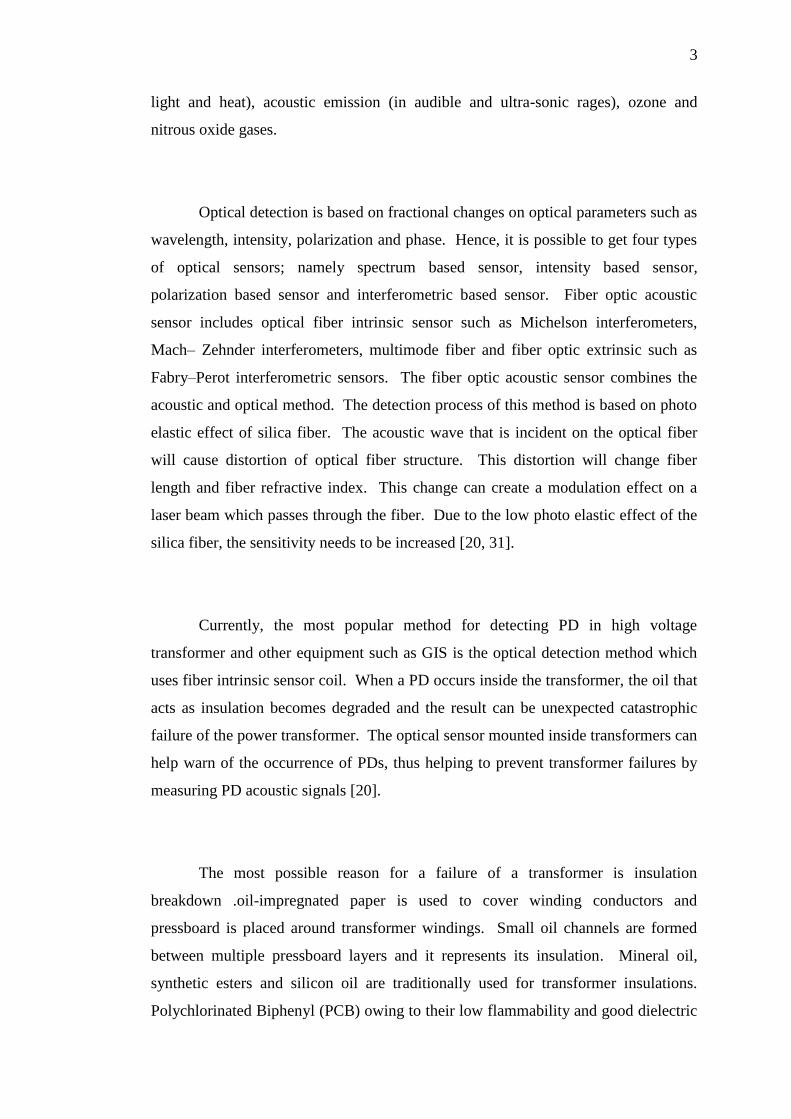
Optical detection is based on fractional changes on optical parameters such as
wavelength, intensity, polarization and phase. Hence, it is possible to get four types
of optical sensors; namely spectrum based sensor, intensity based sensor,
polarization based sensor and interferometric based sensor. Fiber optic acoustic
sensor includes optical fiber intrinsic sensor such as Michelson interferometers,
Mach– Zehnder interferometers, multimode fiber and fiber optic extrinsic such as
Fabry–Perot interferometric sensors. The fiber optic acoustic sensor combines the
acoustic and optical method. The detection process of this method is based on photo
elastic effect of silica fiber. The acoustic wave that is incident on the optical fiber
will cause distortion of optical fiber structure. This distortion will change fiber
length and fiber refractive index. This change can create a modulation effect on a
laser beam which passes through the fiber. Due to the low photo elastic effect of the
silica fiber, the sensitivity needs to be increased [20, 31].
Currently, the most popular method for detecting PD in high voltage
transformer and other equipment such as GIS is the optical detection method which
uses fiber intrinsic sensor coil. When a PD occurs inside the transformer, the oil that
acts as insulation becomes degraded and the result can be unexpected catastrophic
failure of the power transformer. The optical sensor mounted inside transformers can
help warn of the occurrence of PDs, thus helping to prevent transformer failures by
measuring PD acoustic signals [20].
The most possible reason for a failure of a transformer is insulation
breakdown .oil-impregnated paper is used to cover winding conductors and
pressboard is placed around transformer windings. Small oil channels are formed
between multiple pressboard layers and it represents its insulation. Mineral oil,
synthetic esters and silicon oil are traditionally used for transformer insulations.
Polychlorinated Biphenyl (PCB) owing to their low flammability and good dielectric

4
properties was initially used as insulating oil. Conversely due to their negative
environmental impact, they are no more used in many countries including Sri Lanka.
Silicon also has a very low flammability but it is the most expensive oil of all types.
Currently, scientists are looking for alternatives for these nonrenewable sources,
which are also environmental friendly.
Mineral oil has been used for a long time as insulating oil for large power
transformers. Recently, on the issues of depletion of resources and environmental
damage at leakage, demand on environment-friendly insulating oil is increasing.
Various vegetable oils have been investigated especially the palm oil due to it is
advantages of productivity, good biodegradability, excellent insulating performance,
high cooling ability and good oxidation stability, therefor in this study oil palm will
be used.
Recently, vegetable oil based insulating liquid has been studied as a substitute
of mineral insulating oil, because it is almost fully biodegradable and its flash point
exceeds 300 c and it is cheap price and availability in the market.
Recent developments that have improved the electrical properties of
vegetable insulating oil have led to more research interests in the application of
vegetable oil paper insulation. The development of vegetable oil leads to many
problems of oil paper insulation. The dielectric properties of the vegetable oils need
to be further studied so this new type of insulating oil can be used in power
transformers [21].
In this work will study the characteristic of multi-mode optical sensor for
partial discharge signal monitoring in high voltage transformer with natural oil (palm
oil), data obtained and analyzed in form of time and frequency domain and compare
with conventional sensor

5
1.2 Background of Research
Partial discharges are the result of local enhancements of the electric field in
non-homogenous areas, either in gaseous, liquid or solid media. They produce quick
transfers of charge in localized areas and, consequently, create a high-frequency
electric impulse that propagates through the electric circuit. For a short time have
partial discharges usually no effects to the insulating material but the long time
influence shows a destructive effect predominantly on organic insulation systems,
which degrade the electrical characteristics of the insulation or the insulation
systems. The result is a further degradation of the insulation system and may
therefore lead to a failure of the device.
Fiber optics, though used extensively in the modern world, is a fairly simple,
and relatively old, technology. Guiding of light by refraction, the principle that
makes fiber optics possible, was first demonstrated by Daniel Colladon and Jacques
Babinet in Paris in the early 1840s.
In the 1840s, physicists Daniel Collodon and Jacques Babinet showed that
light could be directed along jets of water for fountain displays. In 1854, John
Tyndall, a British physicist, demonstrated that light could travel through a curved
stream of water thereby proving that a light signal could be bent. He proved this by
setting up a tank of water with a pipe that ran out of one side. As water flowed from
the pipe, he shone a light into the tank into the stream of water. As the water fell, an
arc of light followed the water down.
Alexander Graham Bell patented an optical telephone system called the
photophone in 1880. The laser was introduced in 1958 as a efficient source of light.
The concept was introduced by Charles Townes and Arthur Schawlow to show that
masers could be made to operate in optical and infrared regions. In 1961, Elias
Snitzer of American Optical published a theoretical description of single mode fibers

6
whose core would be so small it could carry light with only one wave-guide mode.
Snitzer was able to demonstrate a laser directed through a thin glass fiber which was
sufficient for medical applications. In 1970, the goal of making single mode fibers
with attenuation less then 20dB/km was reached by scientists at Corning Glass
Works. This was achieved through doping silica glass with titanium. Also in 1970,
Morton Panish and Izuo Hayashi of Bell Laboratories, along with a group from the
Ioffe Physical Institute in Leningrad, demonstrated a semiconductor diode laser
capable of emitting continuous waves at room temperature. In 1991, Desurvire and
Payne demonstrated optical amplifiers that were built into the fiber-optic cable itself.
The all-optic system could carry 100 times more information than cable with
electronic amplifiers. Also in 1991, photonic crystal fiber was developed. This fiber
guides light by means of diffraction from a periodic structure rather then total
internal reflection which allows power to be carried more efficiently then with
conventional fibers therefore improving performance.
Acoustic detection with fiber 0ptic based sensors is possible if an acoustic
wave is able to transfer energy to a fiber. The first successful application of optical-
fiber sensors to PD detection was reported in 1996 by Zargari and Blackburn. They
developed an intrinsic fiber sensor based on a Michelson interferometric
configuration.
In 1998, the same authors worked out another non-intrusive fiber-optic sensor
for PD detection that is mounted externally on brushing of a current transformer.
The optical detection method based on the acoustic waves that produced by
the partial discharge inside the oil tank in power transformer. The interaction of
acoustic waves at sonic and ultrasonic frequencies with the optical fiber produces a
pressure on the optical fiber. For the range of ultrasonic frequencies, the acoustic
pressure on the fiber is axisymmetric and uniform along the fiber, and hence
producing a uniform radial pressure on the fiber. The pressure sensitivity of fibers is
7
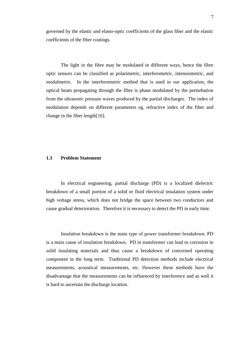
governed by the elastic and elasto-optic coefficients of the glass fiber and the elastic
coefficients of the fiber coatings.
The light in the fibre may be modulated in different ways, hence the fibre
optic sensors can be classified as polarimetric, interferometric, intensiometric, and
modalmetric. In the interferometric method that is used in our application, the
optical beam propagating through the fibre is phase modulated by the perturbation
from the ultrasonic pressure waves produced by the partial discharges. The index of
modulation depends on different parameters eg. refractive index of the fiber and
change in the fiber length[16].
1.3 Problem Statement
In electrical engineering, partial discharge (PD) is a localized dielectric
breakdown of a small portion of a solid or fluid electrical insulation system under
high voltage stress, which does not bridge the space between two conductors and
cause gradual deterioration. Therefore it is necessary to detect the PD in early time.
Insulation breakdown is the main type of power transformer breakdown. PD
is a main cause of insulation breakdown. PD in transformer can lead to corrosion in
solid insulating materials and thus cause a breakdown of concerned operating
component in the long term. Traditional PD detection methods include electrical
measurements, acoustical measurements, etc. However these methods have the
disadvantage that the measurements can be influenced by interference and as well it
is bard to ascertain the discharge location.

8
The light detection method which is discussed in this study can overcome the
above disadvantages to some extent. Optical method that uses optical fiber sensor
which is small in size, highly sensitive and light weight, and possesses high
frequency response and significant immunity against electromagnetic interference,
can measure a wide range of chemical and physical parameters at ease. This features
made the optical method more suitable than the others methods especially for the
power transformer.
Mineral oil, synthetic esters and silicon oil are traditionally used for
transformer insulations because their low flammability and good dielectric properties
but due to their negative environmental impact, they are no more used. Silicon also
has a very low flammability but it is the most expensive oil of all types. Currently,
scientists are looking for alternatives for these nonrenewable sources, which are also
environmental friendly.
Recently, vegetable oil based insulating liquid has been studied as a substitute
of mineral insulating oil, because it is almost fully biodegradable and its flash point
exceeds 300 c and it is cheap price and availability in the market. The development
of vegetable oil leads to many problems of oil paper insulation. The dielectric
properties of the vegetable oils need to be further studied so this new type of
insulating oil can be used in power transformers.
1.4 Objectives of Research
1- To detect and analysis the partial discharge phenomena using multi-mode
fiber optical sensor in natural oil-palm

9
2- To compare the result and the data gained from this experiment with
electrical (capacitive) Sensor detection data and waveform result.
1.5 Scope of Research
The scope of this work is described below:
In this work a multimode optical fiber sensor would be used to detect PD in
transformer because it has the advantages such as: small size and weight, enormous
potential bandwidth, immunity to interference and crosstalk, electrical isolation,
signal security, low transmission loss.
This study would confind in the high voltage range upto 1-20 kV applied to
the electrode of the discharge reactor. This study would confined in the comparison
of two sensors; optical fiber sensor and capacitve sensor. Also in this study the oil
that used in this expermental work is a palm oil because it is so cheap and
environmental friendly.
1.6 Significance of the Study
As mentioned above, the convention techniques of detection for partial
discharges are expensive and have drawbacks in accuracy. The optical fiber sensor
technique can also be used as an inexpensive alternative for the detection of PD in
heavy transformers to monitor the efficiency and working of the transformer. The

10
optical fiber sensor technique is inexpensive and more reliable than conventioonal
sensors and provide safty due to total isolation from the line high voltage.

62
REFERENCES
[1] Achillides Z., Georghiou G., and Kyriakides E.. Partial Discharges and
Associated Transients: The Induced Charge Concept versus Capacitive
Modeling. IEEE Transactions on Dielectrics and Electrical Insulation, vol.
15, no. 6, pp. 1507–1516. 2008.
[2] Adhikari D., Hepburn D. M., and Stewart B. G. Comparison of Partial
Discharge Characteristics and Degradation in Several Polymeric Insulators.
IET Science, Measurement & Technology, vol. 6, no. 6, p. 474, 2012.
[3] Kasten D. G., Sebo S. a., Grosjean D. F., and Schweickart D. L. Partial
Discharge Measurements in Air and Argon at Low Pressures with and
without a Dielectric Barrier. IEEE Transactions on Dielectrics and Electrical
Insulation, vol. 12, no. 2, pp. 362–373, Apr. 2005.
[4] Posada-Roman J., Garcia-Souto J. a, and Rubio-Serrano J. Fiber Optic Sensor
for Acoustic Detection of Partial Discharges in Oil-Paper Insulated Electrical
Systems. Sensors (Basel, Switzerland), vol. 12, no. 4, pp. 4793–802, Jan.
2012.
[5] Chen G. and Baharudin F. Partial Discharge Modelling based on a
Cylindrical Model in Solid Dielectrics. 2008 International Conference on
Condition Monitoring and Diagnosis, pp. 74–78, 2008.
[6] Edin H. Partial Discharges Studied with Variable Frequency of the Applied
Voltage. 2001.
[7] Niasar M. G., Partial Discharge Signatures of Defects in Insulation Systems
Consisting of Oil and Oil-impregnated Paper. 2012.
[8] Nyanteh Y., Graber L., Edrington C., Srivastava S., and Cartes D. Overview
of Simulation Models for Partial Discharge and Electrical Treeing to

63
Determine Feasibility for Estimation of Remaining Life of Machine
Insulation Systems. pp. 327–332, 2011.
[9] Wagner H.-E., Brandenburg R., Kozlov K. V., Sonnenfeld a., Michel P., and
Behnke J. F. The Barrier Discharge: Basic Properties and Applications to
Surface Treatment. Vacuum, vol. 71, no. 3, pp. 417–436, May 2003.
[10] Veen J. On-line Signal Analysis of Partial Discharges in Medium-Voltage
Power Cables Jeroen Veen. .
[11] Elfaraskoury A., Mokhtar M., Mehanna M., and Gouda O. Conventional and
Un-Conventional Partial Discharge Detection Methods in High Voltage
XLPE Cable Accessories. vol. 1, no. 4, pp. 170–176, 2012.
[12] Strehl T. On- and Off-Line Measurement, Diagnostics and Monitoring of
Partial Discharges on High-Voltage Equipment. no. September, pp. 1–9,
2000.
[13] Phung B. T., Blackburn T. R., and Liu Z. Acoustic Measurements Of Partial
Discharge Signals.
[14] Babnik T. and Street G. Data Mining on a Transformer Partial Discharge
Data Using the Self-organizing Map. pp. 444–452, 2007.
[15] Kästner B. Localizing Partial Discharge in Power Transformers by
Combining Acoustic and Different Electrical Methods By. pp. 1–14.
[16] Abbas Z., Blackburn R. Application of Optical Fibre Sensor for Partial
Discharge Detection in High-voltage Power Equipment. Department of
Electric Power Engineering The University of New South Wales, IEEE
[17] Yaacob MM, AlSaedi MA, Abdullah Al Gizi, Zareen N. (2013). Partial
Discharge Signal Detection using Ultra High Frequency Method in High
Voltage Power Equipments: A Review.p1-3.
[18] Yaacob MM, Alsaedi M. A.. (2012). Review of Partial Discharge Signal
Monitoring In Power Transformer Using Chromatic Approach.
[19]. Guangning W. (2000). The Study on Partial Discharge using Light Detection
Method. School of Electrical Engineering Southwest Jiaotong University,
Conference Record of the 2000 IEEE International Symposium on Electrical
Insulation.
[20] Yaacob MM, Malik Abdulrazzaq Alsaedi, Aminudin Aman, Abdullah J. H.
Al Gizi. (2012). Review on Partial Discharge Detection Techniques Related
to High Voltage Power Equipment Using Different Sensors, Institute of High

64
Voltage and High Current. Faculty of Electrical Engineering, University
Technology Malaysia.p1-5
[21] Li, J., et al. Dielectric Properties of Rapeseed Oil Paper Insulation. in
Electrical Insulation and Dielectric Phenomena, 2007. CEIDP 2007. Annual
Report-Conference on. 2007. IEEE.
[22] Kwan, S., Principles of Optical Fibers.
[23] Blackburn, T., B. Phung, and R. James. Optical Fibre Sensor for Partial
Discharge Detection and Location in High-Voltage Power Transformer. in
Dielectric Materials, Measurements and Applications, 1992., Sixth
International Conference on. 1992. IET.
[24] Strehl T. On- and Off-Line Measurement, Diagnostics and Monitoring of
Partial Discharges on High-Voltage Equipment. no. September, pp. 1–9,
2000.
[25] Lindell E., Bengtsson T., Blennow J., and Gubanski S. Measurement of
Partial Discharges at Rapidly Changing Voltages. IEEE Transactions on
Dielectrics and Electrical Insulation, vol. 15, no. 3, pp. 823–831, Jun. 2008.
[26] Khor K. J. Partial Discharge Propagation and Sensing in Overhead Power
Distribution Lines Partial Discharge Propagation and Sensing in Overhead
Power Distribution Lines,‖ 2010.
[27] Centre E. B. and Kingdom U. Application Notes for On-Line Partial
Discharge (PD) Testing & PD Site Location (Mapping) of Medium Voltage
(MV) & High Voltage (HV) Cables On-Line Partial Discharge Detection
within MV and HV Cables, no. 4, 2009.
[28] Strehl T. On- and Off-Line Measurement, Diagnostics and Monitoring of
Partial Discharges on High-Voltage Equipment. no. September, pp. 1–9,
2000.
[29] Boisseau C. Instrument Transformers On Line Monitoring by Means of
Partial Discharge Measurement. 7-th ISH Conf.,Vol. 7, pp. 123-126, Dresden,
Germany, Aug.26-30, 1991.
[30] Jung-Ryul Lee, Hiroshi Tsuda, A Novel Fiber Bragg Grating Acoustic
Emission Sensor Head for Mechanical Tests, Scripta Materialia, Elsevier,
Vol. 53, No. 10, 2005: 1181-1186.
[31] Yaacob MM and Alsaedi, MA. Detection and Wavelet Analysis of Acoustic
Emission Signal from Partial Discharge Captured by Multimode Optical

65
Fiber and Piezoelectric Sensors in Insulation Oil, International Journal of
Physical Sciences, Vol. 8(21), 1149-1160, 9 June, 2013 (IF 0.554).
[32] Yaacob MM and Alsaedi, MA, In situ Detection of Partial Discharge Using
Leakage Current, Fiber Optic Sensor and Piezoelectric Sensor Techniques,
Advanced Materials Research Vol. 845, 277-282 (Scopus)
[33] Yaacob MM, Alsaedi, MA, and Iqbal S.M.Z. A Study of The Sensitivity of
Multimode Optical Fiber Acoustic Sensors and Piezoelectric Film Sensors for
Acoustic Emission Monitoring of Partial Discharge in Oil Insulation, Optical
Review Springer, manuscript no : OR12071R (Springer, 2013)(IF=0.75)(in-
press).


![Sumber Manusia dan Kelebihan Daya Saing Lokasi Industri ...journalarticle.ukm.my/632/1/akademika74[01].pdf · Sumber Manusia dan Kelebihan Daya Saing Lokasi Industri Barangan ElektrikAkademika](https://static.fdocuments.in/doc/165x107/5c85fed109d3f289588ce4ae/sumber-manusia-dan-kelebihan-daya-saing-lokasi-industri-01pdf-sumber-manusia.jpg)