CHARACTERISTICS OF HYDRAULIC JUMP ON CORRUGATED …investigating hydraulic jump characteristics on...
8
International Research Journal of Engineering and Technology (IRJET) e-ISSN: 2395 -0056 Volume: 03 Issue: 05 | May-2016 www.irjet.net p-ISSN: 2395-0072 © 2016, IRJET | Impact Factor value: 4.45 | ISO 9001:2008 Certified Journal | Page 1764 CHARACTERISTICS OF HYDRAULIC JUMP ON CORRUGATED BEDS Madhura M.Deshpande 1 , Vijay R. Thombare 2 , S.D.Talegaonkar 3 1 Research Scholar, M. Tech Civil (Hydraulic Engineering) Bharati Vidyapeeth Deemed University College of engineering, Pune-43 1 2 Associate Professor, Department of Civil Engineering, Bharati Vidyapeeth Deemed University College of engineering, Pune-43 2 3 Asst. Professor, Department of Civil Engineering, Bharati Vidyapeeth Deemed University College of engineering, Pune-43 3 --------------------------------------------------***----------------------------------------------------------- ABSTRACT- Hydraulic jumps are frequently used for excessive kinetic energy dissipation under hydraulic structures like spillways, chutes, gates, drops etc. and the jumps are often generated with the assistant of baffle blocks and kept inside the stilling basin. In this research the effect of spaced and staggered semi-circular strip corrugated beds on characteristics of hydraulic jump has been experimentally investigated. Comparison between different corrugation heights and spacing is also experimentally examined.Seventy experimental runs were carried out considering wide range of Froude numbers ranging from 2.5 to 6.2. Relative roughness ranges from 0.3 to 0.8 of corrugated shapes were studied under different flow conditions. Performance of hydraulic jump on corrugated beds by varying the roughness intensity by 50%, 33%, 25% and 20% respectively and by keeping the roughness intensity same i.e. 25%for getting optimum results was also experimentally investigated. The result of this study confirms that for spaced and staggered semi- circular strips the sequent depths were reduced by average values 29% and 34% respectively, length of jump reduced by average values 21% and 24% respectively while creates a high energy loss of average values 34.6% and 36.6% respectively compared to a classical hydraulic jump respectively. Shear stress increases eight times than that of smooth bed by staggered corrugated bed. Staggered semi-circular corrugated bed showed optimum results than spaced semi-circular strip beds. Results of the present study were agreed acceptably with the previous studies.The use of corrugated beds reduce the length and depth as well as can decrease the stilling basin installation cost. The results also show the effectiveness of corrugated beds for energy dissipation downstream the hydraulic structures. Finally, it is found that the application of corrugated beds always showed better performance than the smooth bed. Key Words:Hydraulic Jump, Corrugated bed, Sequent depth ratio, Energy dissipation, Bed shear stress. 1. INTRODUCTION Hydraulic jump occurs when a high velocity supercritical flow drops to that of a subcritical flow, the rapid following flow is abruptly slowed and increases its height, converting some of the kinetic energy into potential energy. The condition of occurrence of a hydraulic jump is to change flow suddenly from supercritical flow to subcritical flow, Chow [1]. It occurs in a canal below a regulating sluice, at the toe of a spillway or at the place where a steep channel slope suddenly turns flat. The most effective design of stilling basin depends on shortness of the length of jump, the lowness of the elevation of jump and stability of the jump to make the apron height and length as small as possible. Usually devices such as sills, baffle blocks etc are installed into basin in order to satisfy those requirements. These devices are useful to fix the location of jump and reduce the length of jump. The bottom of the channel is paved to resist scouring; and stilling basin is rarely designed to confine the entire length of the jump, because such a basin would be too expensive (Chow 1959). The present study is an attempt to extend the previous studies by examining the effect of spaced semi- circular strip and staggered semi-circular strip corrugated bed shapes downstream of heading-up structures on characteristics of hydraulic jump. In this study the performance of hydraulic jump on different dimensions spaced strip and staggered semi-circular corrugated bed is examined by changing the roughness intensity as well as by keeping the roughness intensity same and optimum results arrangement is found. The main objective of the study is to investigate the effects of the varying upstream flow parameters, i.e. the supercritical depth,y1 and Froude number, Fr1, through with the boundary roughness parameters such as the corrugation height (t), spacing (s) of the corrugation and roughness arrangement, on the hydraulic jump by keeping roughness intensity different as well as same. To investigate the performance of hydraulic jump by increasing the corrugation height (t). Energy dissipation rates, bed shear stress, variations in
Transcript of CHARACTERISTICS OF HYDRAULIC JUMP ON CORRUGATED …investigating hydraulic jump characteristics on...
International Research Journal of Engineering and Technology (IRJET) e-ISSN: 2395 -0056
Volume: 03 Issue: 05 | May-2016 www.irjet.net p-ISSN: 2395-0072
© 2016, IRJET | Impact Factor value: 4.45 | ISO 9001:2008 Certified Journal | Page 1764
CHARACTERISTICS OF HYDRAULIC JUMP ON CORRUGATED BEDS
Madhura M.Deshpande1, Vijay R. Thombare2, S.D.Talegaonkar3
1Research Scholar, M. Tech Civil (Hydraulic Engineering) Bharati Vidyapeeth Deemed University College of engineering, Pune-431
2Associate Professor, Department of Civil Engineering, Bharati Vidyapeeth Deemed University College of engineering, Pune-432
3Asst. Professor, Department of Civil Engineering, Bharati Vidyapeeth Deemed University College of engineering, Pune-433
--------------------------------------------------***-----------------------------------------------------------
ABSTRACT- Hydraulic jumps are frequently used for
excessive kinetic energy dissipation under hydraulic
structures like spillways, chutes, gates, drops etc. and the
jumps are often generated with the assistant of baffle
blocks and kept inside the stilling basin. In this research
the effect of spaced and staggered semi-circular strip
corrugated beds on characteristics of hydraulic jump has
been experimentally investigated. Comparison between
different corrugation heights and spacing is also
experimentally examined.Seventy experimental runs were
carried out considering wide range of Froude numbers
ranging from 2.5 to 6.2. Relative roughness ranges from
0.3 to 0.8 of corrugated shapes were studied under
different flow conditions. Performance of hydraulic jump
on corrugated beds by varying the roughness intensity by
50%, 33%, 25% and 20% respectively and by keeping the
roughness intensity same i.e. 25%for getting optimum
results was also experimentally investigated. The result of
this study confirms that for spaced and staggered semi-
circular strips the sequent depths were reduced by
average values 29% and 34% respectively, length of jump
reduced by average values 21% and 24% respectively
while creates a high energy loss of average values 34.6%
and 36.6% respectively compared to a classical hydraulic
jump respectively. Shear stress increases eight times than
that of smooth bed by staggered corrugated bed.
Staggered semi-circular corrugated bed showed optimum
results than spaced semi-circular strip beds. Results of the
present study were agreed acceptably with the previous
studies.The use of corrugated beds reduce the length and
depth as well as can decrease the stilling basin installation
cost. The results also show the effectiveness of corrugated
beds for energy dissipation downstream the hydraulic
structures. Finally, it is found that the application of corrugated beds always showed better performance than the smooth bed.
Key Words:Hydraulic Jump, Corrugated bed, Sequent depth ratio, Energy dissipation, Bed shear stress.
1. INTRODUCTION
Hydraulic jump occurs when a high velocity supercritical flow drops to that of a subcritical flow, the rapid following flow is abruptly slowed and increases its height, converting some of the kinetic energy into potential energy. The condition of occurrence of a hydraulic jump is to change flow suddenly from supercritical flow to subcritical flow, Chow [1]. It occurs in a canal below a regulating sluice, at the toe of a spillway or at the place where a steep channel slope suddenly turns flat.
The most effective design of stilling basin depends on shortness of the length of jump, the lowness of the elevation of jump and stability of the jump to make the apron height and length as small as possible. Usually devices such as sills, baffle blocks etc are installed into basin in order to satisfy those requirements. These devices are useful to fix the location of jump and reduce the length of jump. The bottom of the channel is paved to resist scouring; and stilling basin is rarely designed to confine the entire length of the jump, because such a basin would be too expensive (Chow 1959). The present study is an attempt to extend the previous studies by examining the effect of spaced semi-circular strip and staggered semi-circular strip corrugated bed shapes downstream of heading-up structures on characteristics of hydraulic jump. In this study the performance of hydraulic jump on different dimensions spaced strip and staggered semi-circular corrugated bed is examined by changing the roughness intensity as well as by keeping the roughness intensity same and optimum results arrangement is found.
The main objective of the study is to investigate the effects of the varying upstream flow parameters, i.e. the supercritical depth,y1 and Froude number, Fr1, through with the boundary roughness parameters such as the corrugation height (t), spacing (s) of the corrugation and roughness arrangement, on the hydraulic jump by keeping roughness intensity different as well as same. To investigate the performance of hydraulic jump by increasing the corrugation height (t). Energy dissipation rates, bed shear stress, variations in
International Research Journal of Engineering and Technology (IRJET) e-ISSN: 2395 -0056
Volume: 03 Issue: 05 | May-2016 www.irjet.net p-ISSN: 2395-0072
© 2016, IRJET | Impact Factor value: 4.45 | ISO 9001:2008 Certified Journal | Page 1765
jump lengths and sequent depth ratios obtained for different roughness arrangements are covered in this study on hydraulic jumps on corrugated beds and on smooth channels.
The vital aim of study is to reach the hopeful results on corrugated beds as reduction in jump length and tail water depth moreover increased energy dissipation compared to jumps on smooth beds. The other prospect is to produce the reduction in jump lengths and required tail water depths in addition the increment in energy loss along the bed by generating third dimensional effects in the turbulent flow section and this is supposed to be grasped by breaking the strip elements into three equal parts and installing them on the bed in a staggered mode.
2. METHODOLOGY AND EXPERIMENTS
2.1 Experimental Set-up
The experiments were carried out in the Fluid Mechanics Laboratory at Bharati Vidyapeeth Deemed University College of Engineering Pune in 2016. A rectangular metal-glass recirculation tilting flume of 10 m long, 0.3 m wide and 0.6 m high was used for the experiments see Figure (4.1). The side walls of the flume were made of acrylic.The middle 6 m lengths portion of side walls of the flume were made of transparent acrylic sheets to facilitate the observation process. A15 hp, centrifugal pump is used to supply water from an underground storage tank in the laboratory and transported to the main tower tank (Overhead tank).The flow would then enter the Inlet chamber of the flume from the head tank. The inlet chamber has a mesh arrangement which is used to provide an even flow distribution across the flume. To control the water flow rate, a regulating valve is installed on the supply pipe line just before the inlet chamber. Tail water depth is controlled by an adjustable flap gate (tail gate) located at the end of the flume. In all the experiments, the tail gate is adjusted so that the jumps are formed on the corrugated beds. Water has been collected in a regulating basin following the free fall formed by the tailgate which, again, was connected to a return channel. Discharge measurements have been made by a V-notch with a 90° notch angle. Initially, discharge was calibrated accurately by using volumetric method. Three pointer gauges with Vernier, having precision of 0.1 mm were used to measure the depth of flow at upstream and downstream side along the flume and at V notch. An ogee (overflow) spillway was installed at 5 m length in the flume to produce the hydraulic jump. The corrugated elements were glued on the bed of the flume downstream of spillway.
2.2 Features of the Spillway Used
Ogee (Overflow) Spillway design for present project
purpose
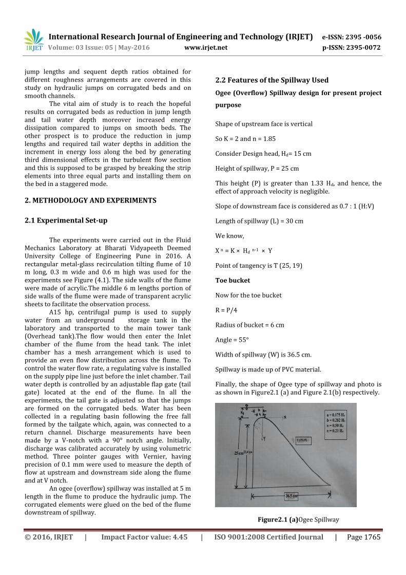
Shape of upstream face is vertical
So K = 2 and n = 1.85
Consider Design head, Hd= 15 cm
Height of spillway, P = 25 cm
This height (P) is greater than 1.33 Hd, and hence, the effect of approach velocity is negligible.
Slope of downstream face is considered as 0.7 : 1 (H:V)
Length of spillway (L) = 30 cm
We know,
X n = K × Hd n-1 × Y
Point of tangency is T (25, 19)
Toe bucket
Now for the toe bucket
R = P/4
Radius of bucket = 6 cm
Angle = 55°
Width of spillway (W) is 36.5 cm.
Spillway is made up of PVC material.
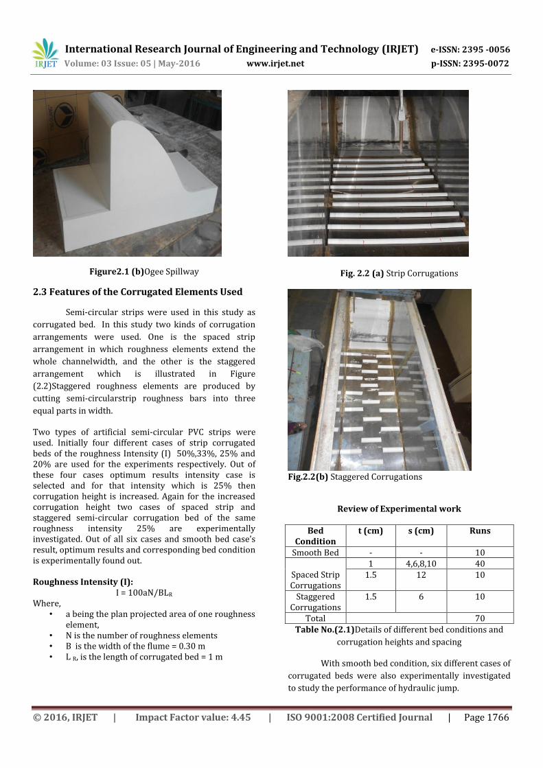
Finally, the shape of Ogee type of spillway and photo is as shown in Figure2.1 (a) and Figure 2.1(b) respectively.
Figure2.1 (a)Ogee Spillway
International Research Journal of Engineering and Technology (IRJET) e-ISSN: 2395 -0056
Volume: 03 Issue: 05 | May-2016 www.irjet.net p-ISSN: 2395-0072
© 2016, IRJET | Impact Factor value: 4.45 | ISO 9001:2008 Certified Journal | Page 1766
Figure2.1 (b)Ogee Spillway
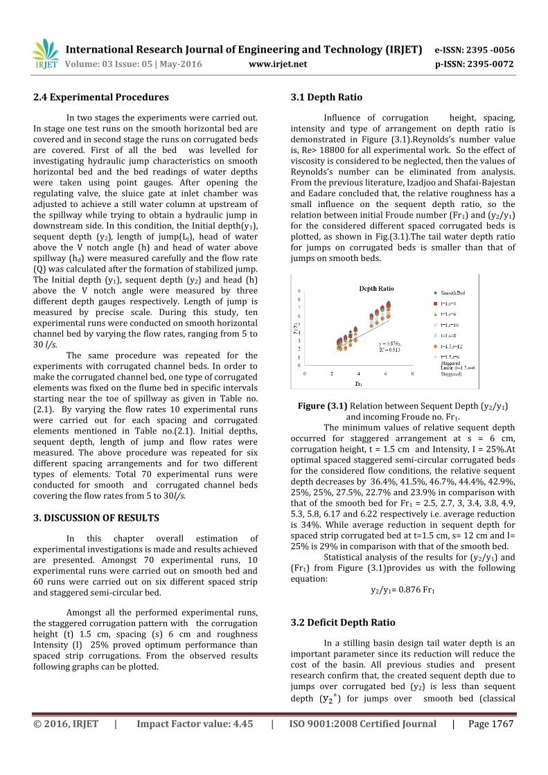
2.3 Features of the Corrugated Elements Used
Semi-circular strips were used in this study as
corrugated bed. In this study two kinds of corrugation
arrangements were used. One is the spaced strip
arrangement in which roughness elements extend the
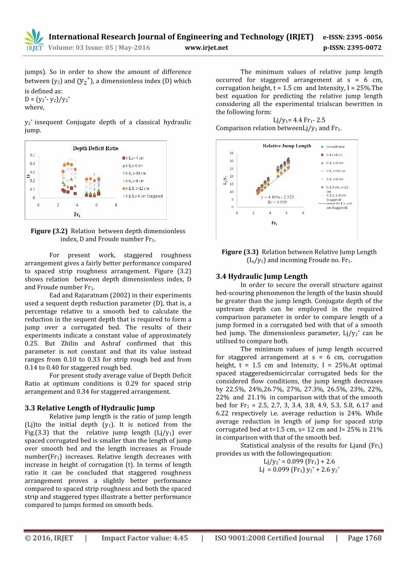
whole channelwidth, and the other is the staggered
arrangement which is illustrated in Figure
(2.2)Staggered roughness elements are produced by
cutting semi-circularstrip roughness bars into three
equal parts in width.
Two types of artificial semi-circular PVC strips were used. Initially four different cases of strip corrugated beds of the roughness Intensity (I) 50%,33%, 25% and 20% are used for the experiments respectively. Out of these four cases optimum results intensity case is selected and for that intensity which is 25% then corrugation height is increased. Again for the increased corrugation height two cases of spaced strip and staggered semi-circular corrugation bed of the same roughness intensity 25% are experimentally investigated. Out of all six cases and smooth bed case’s result, optimum results and corresponding bed condition is experimentally found out. Roughness Intensity (I):
I = 100aN/BLR Where,
• a being the plan projected area of one roughness element,
• N is the number of roughness elements • B is the width of the flume = 0.30 m • L R, is the length of corrugated bed = 1 m
Fig. 2.2 (a) Strip Corrugations
Fig.2.2(b) Staggered Corrugations
Review of Experimental work
Bed Condition
t (cm) s (cm) Runs
Smooth Bed - - 10
Spaced Strip Corrugations
1 4,6,8,10 40 1.5 12 10
Staggered Corrugations
1.5 6 10
Total 70 Table No.(2.1)Details of different bed conditions and
corrugation heights and spacing
With smooth bed condition, six different cases of
corrugated beds were also experimentally investigated
to study the performance of hydraulic jump.
International Research Journal of Engineering and Technology (IRJET) e-ISSN: 2395 -0056
Volume: 03 Issue: 05 | May-2016 www.irjet.net p-ISSN: 2395-0072
© 2016, IRJET | Impact Factor value: 4.45 | ISO 9001:2008 Certified Journal | Page 1767
2.4 Experimental Procedures
In two stages the experiments were carried out. In stage one test runs on the smooth horizontal bed are covered and in second stage the runs on corrugated beds are covered. First of all the bed was levelled for investigating hydraulic jump characteristics on smooth horizontal bed and the bed readings of water depths were taken using point gauges. After opening the regulating valve, the sluice gate at inlet chamber was adjusted to achieve a still water column at upstream of the spillway while trying to obtain a hydraulic jump in downstream side. In this condition, the Initial depth(y1), sequent depth (y2), length of jump(Lj), head of water above the V notch angle (h) and head of water above spillway (hd) were measured carefully and the flow rate (Q) was calculated after the formation of stabilized jump. The Initial depth (y1), sequent depth (y2) and head (h) above the V notch angle were measured by three different depth gauges respectively. Length of jump is measured by precise scale. During this study, ten experimental runs were conducted on smooth horizontal channel bed by varying the flow rates, ranging from 5 to 30 l/s. The same procedure was repeated for the experiments with corrugated channel beds. In order to make the corrugated channel bed, one type of corrugated elements was fixed on the flume bed in specific intervals starting near the toe of spillway as given in Table no. (2.1). By varying the flow rates 10 experimental runs were carried out for each spacing and corrugated elements mentioned in Table no.(2.1). Initial depths, sequent depth, length of jump and flow rates were measured. The above procedure was repeated for six different spacing arrangements and for two different types of elements. Total 70 experimental runs were conducted for smooth and corrugated channel beds covering the flow rates from 5 to 30l/s.
3. DISCUSSION OF RESULTS
In this chapter overall estimation of experimental investigations is made and results achieved are presented. Amongst 70 experimental runs, 10 experimental runs were carried out on smooth bed and 60 runs were carried out on six different spaced strip and staggered semi-circular bed.
Amongst all the performed experimental runs, the staggered corrugation pattern with the corrugation height (t) 1.5 cm, spacing (s) 6 cm and roughness Intensity (I) 25% proved optimum performance than spaced strip corrugations. From the observed results following graphs can be plotted.
3.1 Depth Ratio
Influence of corrugation height, spacing, intensity and type of arrangement on depth ratio is demonstrated in Figure (3.1).Reynolds’s number value is, Re> 18800 for all experimental work. So the effect of viscosity is considered to be neglected, then the values of Reynolds’s number can be eliminated from analysis. From the previous literature, Izadjoo and Shafai-Bajestan and Eadare concluded that, the relative roughness has a small influence on the sequent depth ratio, so the relation between initial Froude number (Fr1) and (y2/y1) for the considered different spaced corrugated beds is plotted, as shown in Fig.(3.1).The tail water depth ratio for jumps on corrugated beds is smaller than that of jumps on smooth beds.
Figure (3.1) Relation between Sequent Depth (y2/y1) and incoming Froude no. Fr1.
The minimum values of relative sequent depth occurred for staggered arrangement at s = 6 cm, corrugation height, t = 1.5 cm and Intensity, I = 25%.At optimal spaced staggered semi-circular corrugated beds for the considered flow conditions, the relative sequent depth decreases by 36.4%, 41.5%, 46.7%, 44.4%, 42.9%, 25%, 25%, 27.5%, 22.7% and 23.9% in comparison with that of the smooth bed for Fr1 = 2.5, 2.7, 3, 3.4, 3.8, 4.9, 5.3, 5.8, 6.17 and 6.22 respectively i.e. average reduction is 34%. While average reduction in sequent depth for spaced strip corrugated bed at t=1.5 cm, s= 12 cm and I= 25% is 29% in comparison with that of the smooth bed. Statistical analysis of the results for (y2/y1) and (Fr1) from Figure (3.1)provides us with the following equation:
y2/y1= 0.876 Fr1
3.2 Deficit Depth Ratio
In a stilling basin design tail water depth is an important parameter since its reduction will reduce the cost of the basin. All previous studies and present research confirm that, the created sequent depth due to jumps over corrugated bed (y2) is less than sequent
depth ( ) for jumps over smooth bed (classical
International Research Journal of Engineering and Technology (IRJET) e-ISSN: 2395 -0056
Volume: 03 Issue: 05 | May-2016 www.irjet.net p-ISSN: 2395-0072
© 2016, IRJET | Impact Factor value: 4.45 | ISO 9001:2008 Certified Journal | Page 1768
jumps). So in order to show the amount of difference
between (y2) and ( ), a dimensionless index (D) which
is defined as: D = (y2
*- y2)/y2*
where,
y2* issequent Conjugate depth of a classical hydraulic
jump.
Figure (3.2) Relation between depth dimensionless index, D and Froude number Fr1.
For present work, staggered roughness arrangement gives a fairly better performance compared to spaced strip roughness arrangement. Figure (3.2) shows relation between depth dimensionless index, D and Froude number Fr1. Ead and Rajaratnam (2002) in their experiments used a sequent depth reduction parameter (D), that is, a percentage relative to a smooth bed to calculate the reduction in the sequent depth that is required to form a jump over a corrugated bed. The results of their experiments indicate a constant value of approximately 0.25. But Zhilin and Ashraf confirmed that this parameter is not constant and that its value instead ranges from 0.10 to 0.33 for strip rough bed and from 0.14 to 0.40 for staggered rough bed. For present study average value of Depth Deficit Ratio at optimum conditions is 0.29 for spaced strip arrangement and 0.34 for staggered arrangement.
3.3 Relative Length of Hydraulic Jump Relative jump length is the ratio of jump length (Lj)to the initial depth (y1). It is noticed from the Fig.(3.3) that the relative jump length (Lj/y1) over spaced corrugated bed is smaller than the length of jump over smooth bed and the length increases as Froude number(Fr1) increases. Relative length decreases with increase in height of corrugation (t). In terms of length ratio it can be concluded that staggered roughness arrangement proves a slightly better performance compared to spaced strip roughness and both the spaced strip and staggered types illustrate a better performance compared to jumps formed on smooth beds.
The minimum values of relative jump length occurred for staggered arrangement at s = 6 cm, corrugation height, t = 1.5 cm and Intensity, I = 25%.The best equation for predicting the relative jump length considering all the experimental trialscan bewritten in the following form:
Lj/y1= 4.4 Fr1- 2.5 Comparison relation betweenLj/y1 and Fr1.
Figure (3.3) Relation between Relative Jump Length (Lj/y1) and incoming Froude no. Fr1.
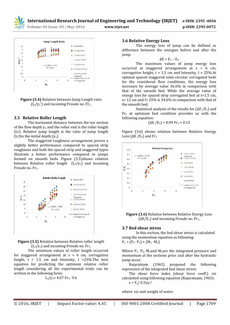
3.4 Hydraulic Jump Length In order to secure the overall structure against bed-scouring phenomenon the length of the basin should be greater than the jump length. Conjugate depth of the upstream depth can be employed in the required comparison parameter in order to compare length of a jump formed in a corrugated bed with that of a smooth bed jump. The dimensionless parameter, Lj/y2
* can be utilised to compare both. The minimum values of jump length occurred for staggered arrangement at s = 6 cm, corrugation height, t = 1.5 cm and Intensity, I = 25%.At optimal spaced staggeredsemicircular corrugated beds for the considered flow conditions, the jump length decreases by 22.5%, 24%,26.7%, 27%, 27.3%, 26.5%, 23%, 22%, 22% and 21.1% in comparison with that of the smooth bed for Fr1 = 2.5, 2.7, 3, 3.4, 3.8, 4.9, 5.3, 5.8, 6.17 and 6.22 respectively i.e. average reduction is 24%. While average reduction in length of jump for spaced strip corrugated bed at t=1.5 cm, s= 12 cm and I= 25% is 21% in comparison with that of the smooth bed. Statistical analysis of the results for Ljand (Fr1) provides us with the followingequation:
Lj/y2* = 0.099 (Fr1) + 2.6
Lj = 0.099 (Fr1) y2* + 2.6 y2
*
International Research Journal of Engineering and Technology (IRJET) e-ISSN: 2395 -0056
Volume: 03 Issue: 05 | May-2016 www.irjet.net p-ISSN: 2395-0072
© 2016, IRJET | Impact Factor value: 4.45 | ISO 9001:2008 Certified Journal | Page 1769
Figure (3.4) Relation between Jump Length ratio (Lj/y2
*) and incoming Froude no. Fr1.
3.5 Relative Roller Length The horizontal distance between the toe section of the flow depth y1 and the roller end is the roller length (Lr). Relative jump length is the ratio of jump length (Lr)to the initial depth (y1). The staggered roughness arrangement proves a slightly better performance compared to spaced strip roughness and both the spaced strip and staggered types illustrate a better performance compared to jumps formed on smooth beds. Figure (3.5)shows relation between Relative roller length (Lr/y1) and incoming Froude no. Fr1.
Figure (3.5) Relation between Relative roller length (Lr/y1) and incoming Froude no. Fr1.
The minimum values of roller length occurred for staggered arrangement at s = 6 cm, corrugation height, t = 1.5 cm and Intensity, I =25%.The best equation for predicting the optimum relative roller length considering all the experimental trials can be written in the following form:
Lr/y1= 4.67 Fr1- 9.6
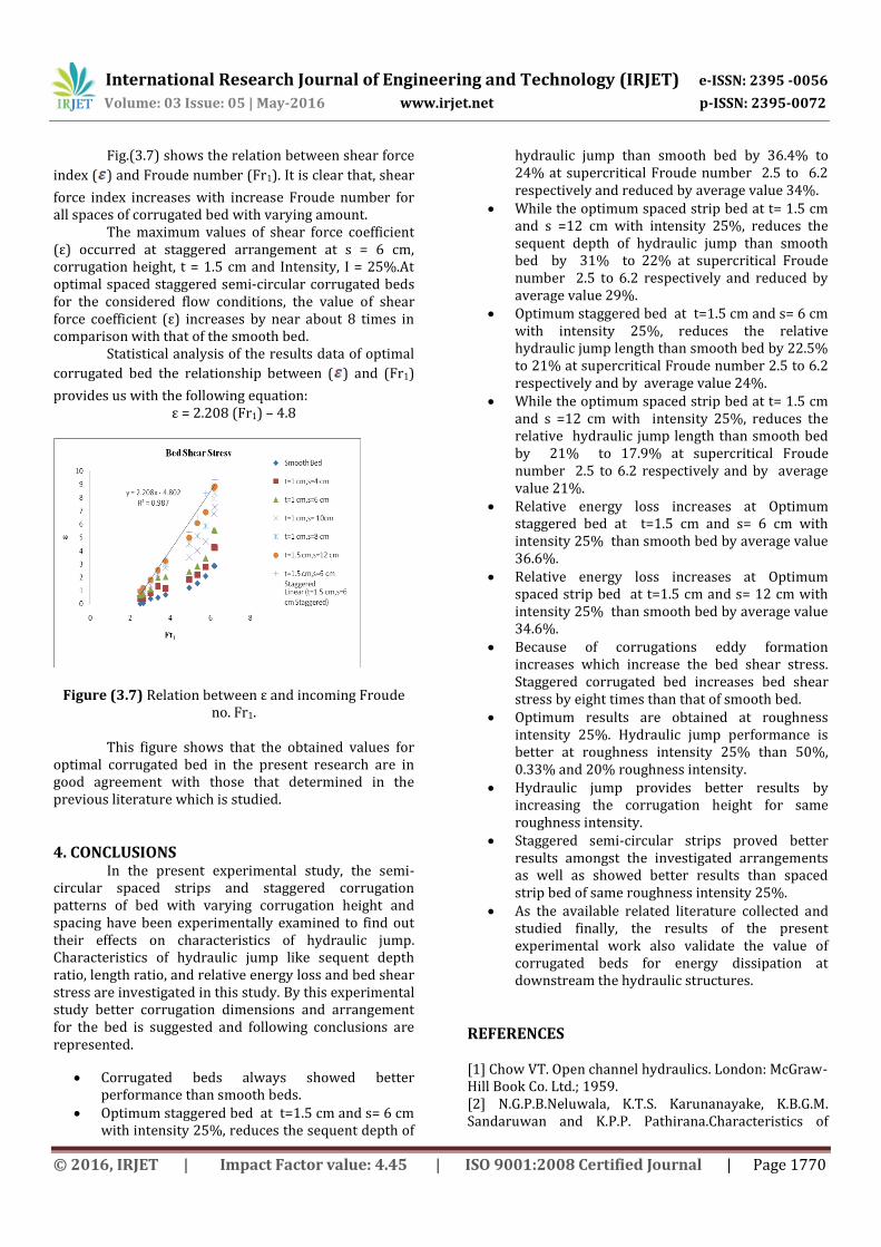
3.6 Relative Energy Loss The energy loss of jump can be defined as difference between the energies before and after the jump.
∆E = E1 – E2
The maximum values of jump energy loss occurred at staggered arrangement at s = 6 cm, corrugation height, t = 1.5 cm and Intensity, I = 25%.At optimal spaced staggered semi-circular corrugated beds for the considered flow conditions, the energy loss increases by average value 36.6% in comparison with that of the smooth bed. While the average value of energy loss for spaced strip corrugated bed at t=1.5 cm, s= 12 cm and I= 25% is 34.6% in comparison with that of the smooth bed. Statistical analysis of the results for (∆E /E1) and Fr1 at optimum bed condition provides us with the following equation:
(∆E /E1) = 0.09 Fr1 + 0.15
Figure (3.6) shows relation between Relative Energy Loss (∆E /E1) and Fr1.
Figure (3.6) Relation between Relative Energy Loss (∆E/E1) and incoming Froude no. Fr1.
3.7 Bed shear stress In this section, the bed shear stress is calculated using the momentum equation as following: Fs = (P1- P2) + (M1- M2) Where P1, P2, M1and M2are the integrated pressure and momentum at the sections prior and after the hydraulic jump occur.
Rajaratnam (1965) proposed the following expression of the integrated bed shear stress:
The shear force index (shear force coeff.). εis calculated using following equation (Rajaratnam, 1965):
ε = Fs/ 0.5γy12
where εis unit weight of water.
International Research Journal of Engineering and Technology (IRJET) e-ISSN: 2395 -0056
Volume: 03 Issue: 05 | May-2016 www.irjet.net p-ISSN: 2395-0072
© 2016, IRJET | Impact Factor value: 4.45 | ISO 9001:2008 Certified Journal | Page 1770
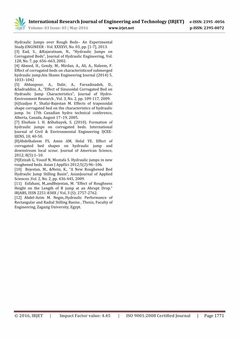
Fig.(3.7) shows the relation between shear force
index ( ) and Froude number (Fr1). It is clear that, shear
force index increases with increase Froude number for all spaces of corrugated bed with varying amount. The maximum values of shear force coefficient (ε) occurred at staggered arrangement at s = 6 cm, corrugation height, t = 1.5 cm and Intensity, I = 25%.At optimal spaced staggered semi-circular corrugated beds for the considered flow conditions, the value of shear force coefficient (ε) increases by near about 8 times in comparison with that of the smooth bed. Statistical analysis of the results data of optimal
corrugated bed the relationship between ( ) and (Fr1)
provides us with the following equation: ε = 2.208 (Fr1) – 4.8
Figure (3.7) Relation between ε and incoming Froude no. Fr1.
This figure shows that the obtained values for optimal corrugated bed in the present research are in good agreement with those that determined in the previous literature which is studied.
4. CONCLUSIONS In the present experimental study, the semi-circular spaced strips and staggered corrugation patterns of bed with varying corrugation height and spacing have been experimentally examined to find out their effects on characteristics of hydraulic jump. Characteristics of hydraulic jump like sequent depth ratio, length ratio, and relative energy loss and bed shear stress are investigated in this study. By this experimental study better corrugation dimensions and arrangement for the bed is suggested and following conclusions are represented.
Corrugated beds always showed better performance than smooth beds.
Optimum staggered bed at t=1.5 cm and s= 6 cm with intensity 25%, reduces the sequent depth of
hydraulic jump than smooth bed by 36.4% to 24% at supercritical Froude number 2.5 to 6.2 respectively and reduced by average value 34%.
While the optimum spaced strip bed at t= 1.5 cm and s =12 cm with intensity 25%, reduces the sequent depth of hydraulic jump than smooth bed by 31% to 22% at supercritical Froude number 2.5 to 6.2 respectively and reduced by average value 29%.
Optimum staggered bed at t=1.5 cm and s= 6 cm with intensity 25%, reduces the relative hydraulic jump length than smooth bed by 22.5% to 21% at supercritical Froude number 2.5 to 6.2 respectively and by average value 24%.
While the optimum spaced strip bed at t= 1.5 cm and s =12 cm with intensity 25%, reduces the relative hydraulic jump length than smooth bed by 21% to 17.9% at supercritical Froude number 2.5 to 6.2 respectively and by average value 21%.
Relative energy loss increases at Optimum staggered bed at t=1.5 cm and s= 6 cm with intensity 25% than smooth bed by average value 36.6%.
Relative energy loss increases at Optimum spaced strip bed at t=1.5 cm and s= 12 cm with intensity 25% than smooth bed by average value 34.6%.
Because of corrugations eddy formation increases which increase the bed shear stress. Staggered corrugated bed increases bed shear stress by eight times than that of smooth bed.
Optimum results are obtained at roughness intensity 25%. Hydraulic jump performance is better at roughness intensity 25% than 50%, 0.33% and 20% roughness intensity.
Hydraulic jump provides better results by increasing the corrugation height for same roughness intensity.
Staggered semi-circular strips proved better results amongst the investigated arrangements as well as showed better results than spaced strip bed of same roughness intensity 25%.
As the available related literature collected and studied finally, the results of the present experimental work also validate the value of corrugated beds for energy dissipation at downstream the hydraulic structures.
REFERENCES
[1] Chow VT. Open channel hydraulics. London: McGraw-Hill Book Co. Ltd.; 1959. [2] N.G.P.B.Neluwala, K.T.S. Karunanayake, K.B.G.M. Sandaruwan and K.P.P. Pathirana.Characteristics of
International Research Journal of Engineering and Technology (IRJET) e-ISSN: 2395 -0056
Volume: 03 Issue: 05 | May-2016 www.irjet.net p-ISSN: 2395-0072
© 2016, IRJET | Impact Factor value: 4.45 | ISO 9001:2008 Certified Journal | Page 1771
Hydraulic Jumps over Rough Beds– An Experimental Study.ENGINEER - Vol. XXXXVI, No. 03, pp. [1-7], 2013. [3] Ead, S., &Rajaratnam, N., “Hydraulic Jumps on Corrugated Beds”, Journal of Hydraulic Engineering, Vol. 128, No. 7, pp. 656–663, 2002. [4] Ahmed, H., Gendy, M., Mirdan, A., Ali, A., Haleem, F. Effect of corrugated beds on characteristicsof submerged hydraulic jump.Ain Shams Engineering Journal (2014) 5, 1033–1042 [5] Abbaspour, A., Dalir, A., Farsadizadeh, D., &Sadraddini, A., “Effect of Sinusoidal Corrugated Bed on Hydraulic Jump Characteristics”, Journal of Hydro-Environment Research , Vol. 3, No. 2, pp. 109-117, 2009. [6]Izadjoo F, Shafai-Bajestan M. Effects of trapezoidal shape corrugated bed on the characteristics of hydraulic jump. In: 17th Canadian hydro technical conference, Alberta, Canada, August 17–19, 2005. [7] Elsebaie I. H. &Shabayek, S. (2010). Formation of hydraulic jumps on corrugated beds. International Journal of Civil & Environmental Engineering IJCEE-IJENS, 10, 40-50. [8]Abdelhaleem FS, Amin AM, Helal YE. Effect of corrugated bed shapes on hydraulic jump and downstream local scour. Journal of American Science, 2012; 8(5):1–10. [9]Ezizah G, Yousif N, Mostafa S. Hydraulic jumps in new roughened beds. Asian J ApplSci 2012;5(2):96–106. [10] Bejestan, M., &Neisi, K., “A New Roughened Bed Hydraulic Jump Stilling Basin”, AsianJournal of Applied Sciences ,Vol. 2, No. 2, pp. 436-445, 2009. [11] Esfahani, M.,andBejestan, M. “Effect of Roughness Height on the Length of B jump at an Abrupt Drop.” IRJABS, ISSN 2251-838X / Vol, 3 (S): 2757-2762. [12] Abdel-Azim M. Negm,.Hydraulic Performance of Rectangular and Radial Stilling Basins , Thesis, Faculty of Engineering, Zagazig University, Egypt.