Characteristics Analysis of Dual Bell Nozzle using ...
8
International Conference on Mechanical, Industrial and Materials Engineering 2017 (ICMIME2017) 28-30 December, 2017, RUET, Rajshahi, Bangladesh. Paper ID: FM-76 Characteristics Analysis of Dual Bell Nozzle using Computational Fluid Dynamics Yeasir Mohammad Akib 1* , Asif Kabir 2* , Mahdi Hasan 3* 1 Department of Industrial and Production Engineering, Rajshahi University of Engineering and Technology, Rajshahi-6204, Bangladesh 2 Department of Mechanical Engineering, Bangladesh University of Engineering & Technology, Dhaka- 1000, Bangladesh 3 Department of Mechanical Engineering, Chittagong University of Engineering & Technology, Chittagong-4349, Bangladesh 1* [email protected], 2* [email protected], 3* [email protected] Abstract Altitude adaptive nozzles have recently got more importance in the field of space science and rocket technology. For future space exploration and space tourism, the combustion system is in the refurbishment for better and robust performance. As a part of this progression, dual bell nozzle is introduced which has dual operating modes (at low and high altitude) without any mechanical activation. The main feature of dual-bell nozzle is that it has two bells separated by an inflection point. For the implementation of this nozzle concept, more and more rapid research should be conducted as there have limited works on this concept. The present study addresses thermodynamic-parameters evolution such as Mach number, pressure and temperature distribution and so on. We have used ANSYS 17.2 fluent to analyze the nozzle geometry. The simulations were performed by using the k-epsilon turbulence model operating at pressure ratios (Chamber to ambient) of 50 and 100. Hybrid initialization is used for solution initialization. The result shows the criterion for the general approach to study the dual bell nozzles. Keywords: Altitude adaption, Dual bell nozzle, Supersonic flow, Inflection point, ANSYS Fluent 1. Introduction Advanced nozzle configurations have been studied in recent years. Plug nozzles, either linear or axisymmetric, nozzles with extendable exit cones (EEC), and dual-bell nozzles are presently under consideration by space industries and agencies as possible main engine candidates for future launchers [1, 2]. Especially Aerospace engineers began to focus on the dual bell nozzles concept as a means for equipping future aerospace vehicles. Currently, several research organizations (NASA, ONERA, etc.) and aviation and space industries (Boeing, Snecma Motors, Dassault, etc.) are working on the improvement of the performances and reliability of the supersonic rocket engine nozzles and space launchers nozzles [3]. The dual-bell concept was first initiated in literature in 1949 by F. Cowles and C. Foster, and was patented in the 1960s by Rocketdyne [4]. Due to the development of modern CFD capabilities, research activity was revived in the 1990s. In 1994, Tests at Rocketdyne conducted by Horn and Fisher and in Europe by the Future European Space Transportation Investigations Program (FESTIP) at the European Space Agency (ESA) investigated the influence of the extension contour geometry on the flow behavior in the first experimental study and confirmed the feasibility of this nozzle design. [4].Horn and Fisher found that a dual-bell nozzle could provide enough thrust to carry 12.1% more payload than a conventional nozzle of the same area ratio [4]. Since the early nineties, many studies, mostly numerical, have been made by Goel and Jensen [6], Hagemann et.al. [7], Immich and Caporicci [8] (within the FESTIP program) to understand and attempted to predict the behavior of this new nozzle concept. A numerical study of the feasibility was made by Karl and Hagemann [9]. Calculations were made to verify the transition duration and stability of the flow in Dual-Bell nozzles. Various parametrical studies have also been realized to understand the §ow phenomena and optimize the contour design [10, 11]. P. Goel and R. Jensen performed the first numerical analysis of dual-bell nozzles, which was published in 1995 [12]. Throughout the 2000s, several numerical and experimental studies of dual- bell nozzles were conducted in the United States and Europe [2].
Transcript of Characteristics Analysis of Dual Bell Nozzle using ...
International Conference on Mechanical, Industrial and Materials Engineering 2017 (ICMIME2017)
28-30 December, 2017, RUET, Rajshahi, Bangladesh.
Paper ID: FM-76
Characteristics Analysis of Dual Bell Nozzle using Computational Fluid
Dynamics
Yeasir Mohammad Akib1*, Asif Kabir2*, Mahdi Hasan3*
1Department of Industrial and Production Engineering, Rajshahi University of Engineering and
Technology, Rajshahi-6204, Bangladesh 2Department of Mechanical Engineering, Bangladesh University of Engineering & Technology, Dhaka-
1000, Bangladesh3Department of Mechanical Engineering, Chittagong University of Engineering &
Technology, Chittagong-4349, Bangladesh 1*[email protected], 2* [email protected], 3*[email protected]
Abstract
Altitude adaptive nozzles have recently got more importance in the field of space science and rocket technology. For
future space exploration and space tourism, the combustion system is in the refurbishment for better and robust
performance. As a part of this progression, dual bell nozzle is introduced which has dual operating modes (at low and
high altitude) without any mechanical activation. The main feature of dual-bell nozzle is that it has two bells separated
by an inflection point. For the implementation of this nozzle concept, more and more rapid research should be
conducted as there have limited works on this concept. The present study addresses thermodynamic-parameters
evolution such as Mach number, pressure and temperature distribution and so on. We have used ANSYS 17.2 fluent
to analyze the nozzle geometry. The simulations were performed by using the k-epsilon turbulence model operating
at pressure ratios (Chamber to ambient) of 50 and 100. Hybrid initialization is used for solution initialization. The
result shows the criterion for the general approach to study the dual bell nozzles.
Keywords: Altitude adaption, Dual bell nozzle, Supersonic flow, Inflection point, ANSYS Fluent
1. Introduction
Advanced nozzle configurations have been studied in recent years. Plug nozzles, either linear or
axisymmetric, nozzles with extendable exit cones (EEC), and dual-bell nozzles are presently under consideration by
space industries and agencies as possible main engine candidates for future launchers [1, 2]. Especially Aerospace
engineers began to focus on the dual bell nozzles concept as a means for equipping future aerospace vehicles.
Currently, several research organizations (NASA, ONERA, etc.) and aviation and space industries (Boeing, Snecma
Motors, Dassault, etc.) are working on the improvement of the performances and reliability of the supersonic rocket
engine nozzles and space launchers nozzles [3].
The dual-bell concept was first initiated in literature in 1949 by F. Cowles and C. Foster, and was patented
in the 1960s by Rocketdyne [4]. Due to the development of modern CFD capabilities, research activity was revived
in the 1990s. In 1994, Tests at Rocketdyne conducted by Horn and Fisher and in Europe by the Future European Space
Transportation Investigations Program (FESTIP) at the European Space Agency (ESA) investigated the influence of
the extension contour geometry on the flow behavior in the first experimental study and confirmed the feasibility of
this nozzle design. [4].Horn and Fisher found that a dual-bell nozzle could provide enough thrust to carry 12.1% more
payload than a conventional nozzle of the same area ratio [4]. Since the early nineties, many studies, mostly numerical,
have been made by Goel and Jensen [6], Hagemann et.al. [7], Immich and Caporicci [8] (within the FESTIP program)
to understand and attempted to predict the behavior of this new nozzle concept. A numerical study of the feasibility
was made by Karl and Hagemann [9]. Calculations were made to verify the transition duration and stability of the
flow in Dual-Bell nozzles. Various parametrical studies have also been realized to understand the §ow phenomena
and optimize the contour design [10, 11]. P. Goel and R. Jensen performed the first numerical analysis of dual-bell
nozzles, which was published in 1995 [12]. Throughout the 2000s, several numerical and experimental studies of dual-
bell nozzles were conducted in the United States and Europe [2].

Fig. 1. The dual-bell nozzle and its two operating modes: sea level (top) and altitude mode (bottom) [5]
A dual-bell nozzle has three characteristic geometric features: an inner base nozzle contour, a wall inflection,
and an outer extension nozzle contour (Fig.1, left). The contour inflection links the base nozzle to the inflection and
provides two stable operation modes. At low altitude, the high ambient pressure forces the flow to separate at the
inflection (Fig.1, upper right). The separation is symmetrical and controlled, limiting the generation of high amplitude
side loads. During the flight, as the ambient pressure decreases, the separation point leaves the inflection and moves
abruptly in the extension down to the nozzle end. This flow transition leads to the high altitude mode (Fig.1, lower
right): the extension is flowing full, offering a large area ratio for improved altitude performances. The area ratio
limitation of conventional nozzles is circumvented for an overall performance gain [13].
2. Nozzle design methodology
A full-length dual-bell nozzle is created using MATLAB. After completing the meshing part using ANSYS,
FLUENT software is used for the analysis of this model. Flow behavior along the nozzle is obtained. Air is taken as
working medium for the nozzle. The area ratio of the dual-bell nozzle was determined using the isentropic flow
relations. The value of the ratio of specific heats was assumed to be 1.23 due to the large assumed pressure and the
high temperatures.
Contour Design
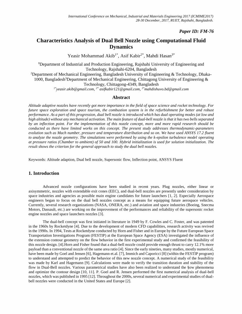
Duel bell nozzle is defined by three section: converging part, throat and diverging part. Converging section
and throat is designed using two circle equation having two different radii (Figure 2). This nozzle feature a divergent
section made of two parts. The first part is known as base or primary nozzle. The second bell (Figure 3) starts with a
slope angle higher than the first bell end, such to yield an attached flow with a centered expansion at the inflection
point in under expanded regime and a separated flow in the second bell in strong over expanded regime[14].
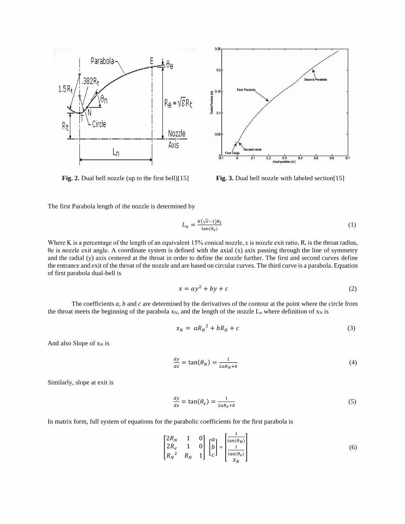
Fig. 2. Dual bell nozzle (up to the first bell)[15]
Fig. 3. Dual bell nozzle with labeled section[15]
The first Parabola length of the nozzle is determined by
𝐿𝑛 =𝐾(√𝜀−1)𝑅𝑡
tan(𝜃𝑒) (1)
Where K is a percentage of the length of an equivalent 15% conical nozzle, ε is nozzle exit ratio, Rt is the throat radius,
θe is nozzle exit angle. A coordinate system is defined with the axial (x) axis passing through the line of symmetry
and the radial (y) axis centered at the throat in order to define the nozzle further. The first and second curves define
the entrance and exit of the throat of the nozzle and are based on circular curves. The third curve is a parabola. Equation
of first parabola dual-bell is
𝑥 = 𝑎𝑦2 + 𝑏𝑦 + 𝑐 (2)
The coefficients a, b and c are determined by the derivatives of the contour at the point where the circle from
the throat meets the beginning of the parabola xN, and the length of the nozzle Ln where definition of xN is
𝑥𝑁 = 𝑎𝑅𝑁2 + 𝑏𝑅𝑁 + 𝑐 (3)
And also Slope of xN is
𝑑𝑦
𝑑𝑥= tan(𝜃𝑁) =
1
2𝑎𝑅𝑁+𝑏 (4)
Similarly, slope at exit is
𝑑𝑦
𝑑𝑥= tan(𝜃𝑒) =
1
2𝑎𝑅𝑒+𝑏 (5)
In matrix form, full system of equations for the parabolic coefficients for the first parabola is
[
2𝑅𝑁 1 02𝑅𝑒 1 0
𝑅𝑁2 𝑅𝑁 1
] [𝑎𝑏𝑐
] = [
1
tan(𝜃𝑁)
1
tan(𝜃𝑒)
𝑥𝑁
] (6)

Full Length of dual-bell nozzle is determined by
𝐿𝑀 =𝐾𝑀(√𝜀−1)𝑅𝑡
tan(𝜃𝑒) (7)
Similarly, full system of equations for the second parabola of the dual-bell nozzle
[
2𝑅𝑀 1 02𝑅𝑒 1 0
𝑅𝑁2 𝑅𝑁 1
] [𝑎′
𝑏′𝑐′
] = [
1
tan(𝜃𝑀)
1
tan(𝜃𝑒)
𝑥𝑀
] (8)
Where a’, b’ and c’ are the coefficients of the second curve. The final design parameters are listed in Table 1.
Table 1. Parabolic coefficients of dual-bell nozzle
Parabolic
Coefficients
Dual-Bell Nozzle
(First Contour)
Dual-Bell Nozzle
(Second Contour)
a 10.2859 21.8315
b 0.5084 -4.7223
c -0.0208 0.5362
Table 2. Design parameters for the
dual-bell nozzle
Length
(m)
Theta_N
(degrees)
Theta_e
(degrees)
Area
Ratio
0.2732 20 9.588 64.5603
3. Modeling and Flow Analysis
Flow through the dual bell nozzle is analyzed with the ANSYS Fluent 17.2. At first, we meshed it in ANSYS
Workbench mesh generator. Mapped face meshing is used for getting good mesh as it consists of square cells of equal
size. Element size of the characteristic cells was 0.002m and the behavior was selected as soft. Our constructed model
has an axial distance from -0.01184 m to 0.78266 m. Different boundary conditions are specified in different positions.
At the inlet, stagnation pressure is 101,325 Pa and stagnation temperature is 300 K. The static pressure at the exit is
2026.5 Pa (PR 50) and 1013.25 Pa (PR 100). In the next step, we have used the Fluent solver. As the flow rocket
nozzle is highly compressible, density based solver is used for calculation. The -epsilon turbulence model was
selected for the simulation due to the focus on the flow structures within the nozzles as it is a commonly used model
for flow analysis in nozzle. Hybrid initialization is used for solution initialization. And the last step is the contour and
velocity vector generation for some major parameters like pressure, temperature and Mach number. We have done it
for pressure ratio 50 and 100.
4. Results and discussion
4.1 Mach Number
For the pressure ratio 50 and 100, the Mach number is subsonic at the inlet. At the starting of the second
parabolic contour, the flow becomes supersonic and slightly hypersonic. The exit Mach number has some variations.
In the boundary layer, the flow becomes supersonic but at the midpoint of the exit, the flow becomes subsonic to
transonic. The observable difference PR (pressure ratio) 50 and 100 is the variation of the Mach number through the
midpoint of the second parabola. Figure 4(A) shows more variation of Mach number than figure 4(B) in the midpoint
of the second parabola.

Fig. 4. Contour of Mach number for pressure ratio (A) 50 and (B) 100
4.2 Mach velocity vector
Mach velocity vectors show the change of Mach numbers with the velocity vectors. Velocity vectors show
the change of Mach numbers same as the Mach number contour for PR 50 and 100. For pressure ratio 50 and 100, the
exit Mach velocity vector becomes subsonic. For figure 5(A), the Mach velocity vector becomes slightly higher than
figure 5(B).
Fig. 5. Contour of Mach velocity vector for pressure ratio (A) 50 and (B) 100
4.3 Static pressure
From figure 6(A) and 6(B), the static pressure shown at the inlet varies from 53.4 kPa to 89 kPa. At the
starting of the first parabola, pressure drops a little bit and stays in the range 32.7-50.5 kPa. Throughout the rest of the
nozzle, the pressure becomes very low.

Fig. 6. Contour of static pressure for pressure ratio (A) 50 and (B) 100
4.4 Total pressure
Total pressure at the inlet is very high for both figure 7(A) and 7(B). It drops significantly from the midpoint
of the second curve and becomes low at the exit. Exit total pressure varies from 17.6 kPa to 0.731 kPa.
Fig. 7. Contour of total pressure for pressure ratio (A) 50 and (B) 100
4.5 Static temperature
Fluent defines the total pressure as a gauge pressure with respect to operating pressure. The static temperature
for both figure 8(A) and 8(B) is like 270-298 K at the inlet and varies gradually through the axial distance. At the exit
midpoint, the temperature for both PR is not same. For figure 8(A), the exit midpoint value is likely 136-174 K
whereas, for figure 8(B), there is a lower temperature like 130 K.

Fig. 8. Contour of static temperature for pressure ratio (A) 50 and (B) 100
4.6 Total temperature
The total temperature for both figure 9(A) and 9(B), it seems high till the starting point of the second
curvature. Then, the temperature varies significantly through the axial distance. At the exit, the temperature varies
from 102-106 K as the exit gas meets the air.
Fig. 9. Contour of total temperature for pressure ratio (A) 50 and (B) 100
5. Verification
In our result section we have already discussed about six parameters. For more consistency, our results are
compared with numerical data calculating by the students of WORCESTER POLYTECHNIC INSTITUTE [15] only
for Mach number. Compared data has given below with error percentage.

Table 3. Calculated Mach number according to ref [15] data
Nozzle position
along center line
Pressure Ratio = 50 Pressure Ratio = 100
OC Ref [15] Error (%) OC Ref [15] Error (%)
Throat 0.99 0.91 8.79 1.04 0.95 9.47
Inflection 5.07 4.82 5.18 5.17 4.90 5.51
Exit 0.35 0.32 9.37 0.44 `0.40 10.00
6. Conclusion
A critical appraisement of dual-bell nozzles was presented in this paper. This paper represents the design of
a dual-bell nozzle profile and the study of the fluid parameters behavior like Mach number, pressure, temperature,
velocity vectors under under-expanded conditions. A code in MATLAB was developed to draw contour design. CFD
calculations were achieved within a numerical domain by applying boundary condition assuming isentropic
environment. Then we have compared our result with ref [15] only for the Mach number contours. For future work,
we can simulate some conditions for over-expansion and compare it with traditional convergent-divergent (CD)
nozzle. Moreover creating a small scaled version of dual bell nozzle can help us for testing it in real conditions.
7. References
[1] Muss, J. A., Nguyen, T. V., Reske, E. J., and McDaniels, D. M., “Evaluation of Altitude Compensating Nozzle Concepts for RLV”, AIAA, 33rd AIAA/ASME/SAE/ASEE Joint Propulsion Conference & Exhibit, Paper 97–3222, Jul. 1997.
[2] Hagemann, G., Immich, H., Nguyen, T. V., and Dumnov, G. E., “Advanced Rocket Nozzles”, Journal of Propulsion and Power, Vol. 14, No. 5, pp. 620–634, Sep-Oct 1998.
[3] H. Kbab, M. Sellam, T. Hamitouche, S. Bergheul and L. Lagab, “Design and performance evaluation of a dual-bell nozzle”, Acta Astronautica, Vol. 130, pp. 52-59, Jan-Feb 2017.
[4] Horn, M., S. Fisher, Dual-bell altitude compensating nozzles. NASA Propulsion Engineering Research Center, 140-147, 1993.
[5] C. Nürnberger-Génin and R. Stark, “Experimental Study of Dual Bell Nozzles”, 2ND EUROPEAN CONFERENCE FOR AEROSPACE SCIENCES (EUCASS), DLR, German Aerospace Center, Lampoldshausen, D-74239, Germany.
[6] Goel, P. and Jensen, R., Numerical Analysis of the Performance of Altitude Compensating Dual-Bell Nozzle Flows, Rocketdyne Division, 1995.
[7] Hagemann, G., and Frey, M. and Manski, D., “A critical Assessment of Dual-Bell Nozzles”, AIAA 97-3299, 1997.
[8] Immich, H. and Caporicci, M., FESTIP Technology Developments in Liquid Rocket Propulsion, AIAA 96-3113, 1996.
[9] Kronmüller, H., Schäfer, K., Strak, R. and Zimmermann, H., Kaltgas-Höhensimulationsprüfstand P6.2 desDLR Lampoldshausen, DGLR, 2002.
[10] Martelli, E., F. Nasuti, and M. Onofri., Numerical parametric analysis of dual-bell nozzle flows. AIAA J. 45:640-50, 2007.
[11] Genin, C., Experimental study of flow behavior and thermal loads in dual bell nozzles. Ph.D. Thesis. Universite de Valenciennes, France, 2010.
[12] Frey, M. & Hagemann, G., “Critical assessment of dual-bell nozzles.” Journal of propulsion and power, 15, 137-143, 1999.
[13] Genin, C., Stark, R., Karl, S., Schneider, D., “Numerical investigation of Dual Bell Nozzle Flow Field”, 48th AIAA/ASME/SAE/ASEE Joint Propulsion Conference & Exhibit, July - Aug 2012.
[14] Francesco Nasuti, Marcello Onofri and Emanuele Martelli, “Numerical Study of Transition between the two operating modes
of Dual-bell nozzles”, 38th AIAA/ASME/SAE/ASEE Joint Propulsion Conference & Exhibit, July 2002.
[15] Kate Davis, Elizabeth Fortner, Michael Heard, Hannah McCallum, and Hunter Putzke, “Experimental and Computational Investigation of a Dual-Bell Nozzle”, 53rd AIAA Aerospace Sciences Meeting, January 2015.