Chapter7 Vector Control of Induction Traction...
76
Chapter 7 Chapter 7 Vector (Field Oriented) Control of AC Vector (Field Oriented) Control of AC Induction Traction Motor Induction Traction Motor Wensheng Song PH.D Email:[email protected] Website: http://tctd.swjtu.edu.cn Train Control & Traction Drive Lab, Southwest Jiaotong University
Transcript of Chapter7 Vector Control of Induction Traction...

Chapter 7Chapter 7
Vector (Field Oriented) Control of AC Vector (Field Oriented) Control of AC Induction Traction Motor Induction Traction Motor
Wensheng Song PH.DEmail:[email protected]: http://tctd.swjtu.edu.cn
Train Control & Traction Drive Lab,Southwest Jiaotong University

2
Electric Railw
ay Traction AC
Drive System
s
DeclarationDeclarationDeclaration
This chapter slide is referenced the presentation files of ECE 8830 course “ Electric Drive ” in Villanova University, USA, which are written by Prof. Pritpal Singh.
Downloading website: http://www.ece.villanova.edu/~singh/
And this version of the slide is updated by Dr. Wensheng Song.

3
Electric Railw
ay Traction AC
Drive System
s
创新、自主研发
OutlineOutline
Introduction Introduction
The Basic Concepts and Principle of FieldThe Basic Concepts and Principle of Field--oriented oriented ControlControl
Direct Rotor FieldDirect Rotor Field--oriented Control Designoriented Control Design
Rotor Flux Vector Estimation of Induction Traction Rotor Flux Vector Estimation of Induction Traction MotorMotor
Indirect Rotor FieldIndirect Rotor Field--orientedoriented Control Design Control Design
Case: Indirect Vector Control of Induction Traction Case: Indirect Vector Control of Induction Traction Motor in CRH2 EMU ApplicationMotor in CRH2 EMU Application
4
Electric Railw
ay Traction AC
Drive System
s
IntroductionIntroductionIntroduction
Scalar control of AC drives produces good steady state performance but poor dynamic response. This manifests itself in the deviation of air gap flux linkages from their set values. This variation occurs in both magnitude and phase.
Vector control (or field oriented control) offers more precise control of AC motors compared to scalar control. They are therefore used in high performance drives where oscillations in air gap flux linkages are intolerable, e.g. robotic actuators, centrifuges, servos, etc.

5
Electric Railw
ay Traction AC
Drive System
s
Introduction (cont’d)Introduction (contIntroduction (cont’’d)d)
Why does vector control provide superior dynamic performance of ac motors compared to scalar control ?
In scalar control there is an inherent coupling effect because both torque and flux are functions of voltage or current and frequency. This results in sluggish response and is prone to instability because of 5th order harmonics. Vector control decouples these effects.

6
Electric Railw
ay Traction AC
Drive System
s
Torque Control of DC MotorsTorque Control of DC MotorsTorque Control of DC Motors
There is a close parallel between torque control of a DC motor and vector control of an AC motor. Therefore, it is useful to review torque control of a DC motor before studying vector control of an AC motor.

7
Electric Railw
ay Traction AC
Drive System
s
Torque Control of DC Motors (cont’d)Torque Control of DC Motors (contTorque Control of DC Motors (cont’’d)d)
A DC motor has a stationary field structure (windings or permanent magnets) and a rotating armature winding supplied by a commutator and brushes. The basic structure and field flux and armature MMF are shown below:

8
Electric Railw
ay Traction AC
Drive System
s
Torque Control of DC Motors (cont’d)Torque Control of DC Motors (contTorque Control of DC Motors (cont’’d)d)
The field flux ψf (λf) produced by field current If is orthogonal to the armature flux ψa (λa) produced by the armature current Ia. The developed torque Te can be written as:
Because the vectors are orthogonal, they are decoupled, i.e. the field current only controls the field flux and the armature current only controls the armature flux.
'e t a fT K I I=

9
Electric Railw
ay Traction AC
Drive System
s
Torque Control of DC Motors (cont’d)Torque Control of DC Motors (contTorque Control of DC Motors (cont’’d)d)
Torque of DC motor
Torque of AC motor
d
sω
sω
mψ
rψ
sdirφ
T
ri−
si
sqi−
mi
ri
rφ
e M a f aT C I I Iϕ= ∝
e ˆ cosM m r rT C Iψ φ= −
e ˆT r rT C Iψ= −
Fig.7-1 Phasors diagram of AC induction motor
10
Electric Railw
ay Traction AC
Drive System
s
Torque Control of DC Motors (cont’d)Torque Control of DC Motors (contTorque Control of DC Motors (cont’’d)d)
DC motor-like performance can be achieved with an induction motor if the motor control is considered in the synchronously rotating reference frame (d-q) where the sinusoidal variables appear as dc quantities in steady state.
Two control inputs isd and isq can be used for a vector controlled inverter as shown on the next slide.

11
Electric Railw
ay Traction AC
Drive System
s
Torque Control of DC Motors (cont’d)Torque Control of DC Motors (contTorque Control of DC Motors (cont’’d)d)
're t sq t sd sqT K i K i iψ= =
r sdiψ ∝Due to
Therefore: We must have andre T rT C iψ= −
r sqi i∝ − How?
With vector control:isd (induction motor) ≡ If (DC motor)isq (induction motor) ≡ Ia (DC motor)
Thus torque is given by:

12
Electric Railw
ay Traction AC
Drive System
s
d-axis is aligned with the rotor field vector, and named the magnetization-axis. The q-axis is defined as leading the d-axis by π/2, and named torque-axis.And the d-q axis frame rotates with synchronous rotating speed ωs ,anticlockwise.
Rotor Field Oriented ControlRotor Field Oriented Control

13
Electric Railw
ay Traction AC
Drive System
s
Voltage equations in dq synchronous rotating frame
Voltage equations in Voltage equations in dqdq synchronous synchronous rotating framerotating frame
dsd ss s s s m s m
sq sqs s s s s m m
rd rdm sl m r r sl r
rq rqsl m m sl r r r
U iR L p L L p LU iL R L p L L pU iL p L R L p LU iL L p L R L p
ω ωω ω
ω ωω ω
+ − −⎡ ⎤ ⎡ ⎤⎡ ⎤⎢ ⎥ ⎢ ⎥⎢ ⎥+⎢ ⎥ ⎢ ⎥⎢ ⎥=⎢ ⎥ ⎢ ⎥⎢ ⎥− + −⎢ ⎥ ⎢ ⎥⎢ ⎥
+⎢ ⎥ ⎢ ⎥⎣ ⎦⎣ ⎦ ⎣ ⎦

14
Electric Railw
ay Traction AC
Drive System
s
Voltage equations in dq synchronous rotating frame
Voltage equations in Voltage equations in dqdq synchronous synchronous rotating framerotating frame
Rotor Voltage Equations:
Stator Voltage Equations:
( ) ( )( ) ( )
( ) ( )( ) ( )
rd r rd m sd r rd s r m sq r rq r rd rd s r rq
rq r rq m sq r rq s r m sd r rd r rq rq s r rd
d du R i L i L i L i L i R idt dtd du R i L i L i L i L i R idt dt
ω ω ψ ω ω ψ
ω ω ψ ω ω ψ
⎧ = + + − − + = + − −⎪⎪⎨⎪ = + + + − + = + + −⎪⎩
( )
( )
sd s sd s sd m rd s rq s sd sd s sq
sq s sq s sq m rq s rd s sq sq s sd
d du R i L i L i R idt dtd du R i L i L i R idt dt
ωψ ψ ωψ
ωψ ψ ωψ
⎧ = + + − = + −⎪⎪⎨⎪ = + + + = + +⎪⎩

15
Electric Railw
ay Traction AC
Drive System
s
Voltage equations in dq synchronous rotating frame
Voltage equations in Voltage equations in dqdq synchronous synchronous rotating framerotating frame
0rd r r rd m sd
rq r rq m sq
L i L iL i L i
ψ ψψ
= = += = +
0 0000
sds s s s m s msd
sqs s s s s m msq
rdm r r
rqsl m sl r r
iR L p L L p LUiL R L p L L pUiL p R L piL L R
ω ωω ω
ω ω
+ − − ⎡ ⎤⎡ ⎤⎡ ⎤⎢ ⎥⎢ ⎥⎢ ⎥ + ⎢ ⎥⎢ ⎥⎢ ⎥ =⎢ ⎥⎢ ⎥⎢ ⎥ +⎢ ⎥⎢ ⎥⎢ ⎥⎢ ⎥⎣ ⎦ ⎣ ⎦ ⎣ ⎦
To induction motor with squirrel cage type rotor.Three-phase rotors are all shorted, and urd=urq=0.
16
Electric Railw
ay Traction AC
Drive System
s
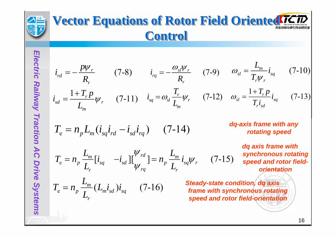
(7-10)msl sq
r r
L iT
ωψ
= (7-8)rrd
r
piRψ
= − (7-9)sl rrq
r
iR
ω ψ= −
1 (7-11)rsd r
m
T piL
ψ+= (7-12)r
sq sl rm
TiL
ω ψ=
e ( ) (7-14)p m sq rd sd rqT n L i i i i= −
e [ ][ ] (7-15)rdm mp sq sd p sq r
rqr r
L LT n i i n iL L
ψψ
ψ= − =
e ( ) (7-16)mp m sd sq
r
LT n L i iL
=
1 (7-13)rsl sq
r sd
T p iT i
ω +=
Vector Equations of Rotor Field Oriented Control
Vector Equations of Rotor Field Oriented Vector Equations of Rotor Field Oriented ControlControl
Steady-state condition, dq axis frame with synchronous rotating speed and rotor field-orientation
dq-axis frame with any rotating speed
dq axis frame with synchronous rotating speed and rotor field-
orientation

17
Electric Railw
ay Traction AC
Drive System
s
Current Decoupling Model of Induction Motor
Current Decoupling Model of Induction Current Decoupling Model of Induction MotorMotor
3/2
aiϕ
−VR
r
mp L
Ln pnJ
×cibi
sαi
sβi
sdi
sqi
rΨ
LT
eTω
m
1r
LT p+

18
Electric Railw
ay Traction AC
Drive System
s
Torque Control of DC Motors (cont’d)Torque Control of DC Motors (contTorque Control of DC Motors (cont’’d)d)
This DC motor-like performance is only possible if isq*
only controls isq and does not affect the flux , i.e. isq
and isd are orthogonal under all operating conditions of the vector-controlled drive.
Thus, vector control should ensure the correct orientation and equality of the command and actual currents.
rψ

19
Electric Railw
ay Traction AC
Drive System
s
Equivalent Circuit of Induction MotorEquivalent Circuit of Induction MotorEquivalent Circuit of Induction Motor
The complex d-q equivalent circuit of an induction motor is shown in the below figure (neglecting rotor leakage inductance).
Fig.7 The complex d-q equivalent circuit in steady state
mr rq sq sq
r
Li i i iL
= = − ≈ −

20
Electric Railw
ay Traction AC
Drive System
s
Equivalent Circuit of Induction Motor (cont’d)Equivalent Circuit of Induction Motor (contEquivalent Circuit of Induction Motor (cont’’d)d)
Since the rotor leakage inductance has been neglected, the rotor flux = , the air gap flux.
The stator current vector Is is the sum of the isd and isq
vectors. Thus, the stator current magnitude, is related to isd and isq by:
rψ mψ
sI
2 2s sd sqI i i= +

21
Electric Railw
ay Traction AC
Drive System
s
Phasor Diagrams for Induction MotorPhasorPhasor Diagrams for Induction MotorDiagrams for Induction Motor
The steady state phasor (or vector) diagrams for an induction motor in the d-q (synchronously rotating) reference frame are shown below:

22
Electric Railw
ay Traction AC
Drive System
s
Phasor Diagrams for Induction Motor (cont’d)PhasorPhasor Diagrams for Induction Motor (contDiagrams for Induction Motor (cont’’d)d)
The rotor flux vector is aligned with the d-axis and the air gap voltage is aligned with the q-axis. The terminal voltage Vs slightly leads the air gap voltage because of the voltage drop across the stator impedance. isq contributes real power across the air gap but isd only contributes reactive power across the air gap.
( )r mψ ψ=
mV

23
Electric Railw
ay Traction AC
Drive System
s
Phasor Diagrams for Induction Motor (cont’d)
PhasorPhasor Diagrams for Induction Motor Diagrams for Induction Motor (cont(cont’’d)d)
The first figure shows an increase in the torque component of current iqs and the second figure shows an increase in the flux component of current, ids. Because of the orthogonal orientation of these components, the torque and flux can be controlled independently. However, it is necessary to maintain these vector orientations under all operating conditions.
How can we control the iqs and ids components of the stator current Is independently with the desired orientation ?

24
Electric Railw
ay Traction AC
Drive System
s
The basic conceptual implementation of vector control is illustrated in the below block diagram:
Principles of Vector ControlPrinciples of Vector ControlPrinciples of Vector Control
ωr
Controller VR-1 2/3Current
fed
Inverter3/2 VR
DC motor-
like+
i*sd
i*sq
ϕ
ωs
i*sα
i*sβ
i*ai*bi*c
iaibic
α
isβ
isd
isq
~
Feedback
IM
Command
ϕ

25
Electric Railw
ay Traction AC
Drive System
s
Principles of Vector Control (cont’d)Principles of Vector Control (contPrinciples of Vector Control (cont’’d)d)
The motor phase currents, ia, ib and ic are converted to isα and isβ in the stationary reference frame. These are then converted to the synchronously rotating reference frame d-q currents, isd and isq.
In the controller two inverse transforms are performed:1) From the synchronous d-q to the
stationary α-β reference frame; 2) From α*- β* to a*, b*, c*.

26
Electric Railw
ay Traction AC
Drive System
s
Principles of Vector Control (cont’d)Principles of Vector Control (contPrinciples of Vector Control (cont’’d)d)
There are two approaches to vector control:
1) Direct field oriented current control- here the rotation angle of the isq vector with respect to the stator flux ψrq’s is being directly determined (e.g. by measuring air gap flux)
2) Indirect field oriented current control- here the rotor angle is being measured indirectly, such as by measuring slip speed.

27
Electric Railw
ay Traction AC
Drive System
s
Direct Vector ControlDirect Vector ControlDirect Vector Control
In direct vector control the field angle is calculated by using terminal voltages and current or Hall sensors or flux sense windings.
A block diagram of a direct vector control method using a PWM voltage-fed inverter is shown on the next slide.

28
Electric Railw
ay Traction AC
Drive System
s
Direct Vector Control (cont’d)Direct Vector Control (contDirect Vector Control (cont’’d)d)

29
Electric Railw
ay Traction AC
Drive System
s
Direct Vector Control (cont’d)Direct Vector Control (contDirect Vector Control (cont’’d)d)
The principal vector control parameters, isd* and isq
*, which are DC values in the synchronously rotating reference frame, are converted to the stationary reference frame (using the vector rotation (VR) block) by using the unit vector cosθs and sinθs.
These stationary reference frame control parameters isα* and isβ * are then changed to the phase current command signals, ia*, ib*, and ic*
which are fed to the PWM inverter.

30
Electric Railw
ay Traction AC
Drive System
s
Direct Vector Control (cont’d)Direct Vector Control (contDirect Vector Control (cont’’d)d)
A flux control loop is used to precisely control the flux. Torque control is achieved through the current isq
*
which is generated from the speed control loop (which includes a bipolar limiter that is not shown). The torque can be negative which will result in a negative phase orientation for isq in the phasor diagram.
How do we maintain isdand isq orthogonality? This is explained in the next slide.

31
Electric Railw
ay Traction AC
Drive System
s
Direct Vector Control (cont’d)Direct Vector Control (contDirect Vector Control (cont’’d)d)
Figure α-β and d-q phasors showing correct rotor flux orientation

32
Electric Railw
ay Traction AC
Drive System
s
Direct Vector Control (cont’d)Direct Vector Control (contDirect Vector Control (cont’’d)d)
Here the d-q frame is rotating at synchronous speed ωs with respect to the stationary reference frame α-β , and at any point in time, the angular position of the d axis with respect to the αaxis is θs (=ωst).
From this phasor diagram we can write:
and
Thus and
cosrr sαψ ψ θ= sinrr sβψ ψ θ=
2 2r r rα βψ ψ ψ= + cos r
sr
αψθψ
=sin rs
r
βψθ
ψ=
These unit vector signals, when used in the vector rotation(VR) block, cause isd to maintain orientation along the d -axis and the isq orientation along the q -axis.

33
Electric Railw
ay Traction AC
Drive System
s
Summary of Salient Features of Vector ControlSummary of Salient Features of Vector ControlSummary of Salient Features of Vector Control
A few of the salient features of vector control are:The frequency ωs of the drive is not controlled (as in scalar control). The motor is “self-controlled” by using the unit vector to help control the frequency and phase. There is no concern about instability because limiting within the safe limit automatically limits operation to the stable region.Transient response will be fast because torque control by isqdoes not affect flux.Vector control allows for speed control in all four quadrants (without additional control elements) since negative torque is directly taken care of in vector control.
sI

34
Electric Railw
ay Traction AC
Drive System
s
Flux Vector EstimationFlux Vector EstimationFlux Vector Estimation
The air gap flux can be directly measured in a machine using specially fitted search coils or Hall effect sensors. However, the drift in the integrator with a search coil is problematic at very low frequencies. Hall effect sensors tend to be temperature-sensitive and fragile.
An alternative approach is to measure the terminal voltage and phase currents of the machine and use these to estimate the flux. These techniques are discussed on the next slides.

35
Electric Railw
ay Traction AC
Drive System
s
Rotor Flux Estimation——U-I ModelRotor Flux EstimationRotor Flux Estimation————UU--I ModelI Model
1.Voltage-Current Model
[ ]( )rr s s s s
m
LU R L p i
L pα α αψ σ= − +
( )rr s s s s
m
LU R L p i
L pβ β βψ σ⎡ ⎤= − +⎣ ⎦
1p
r
m
LLsu α rαψ
1p
r
m
LL rβψ
si α ss
R Lp
σ+
ss
R Lp
σ+
su β
si β
( )( )
s s s s s m r s s s
s s s s s m r s s s
u R i p L i L i R i pu R i p L i L i R i p
α α α α α α
β β β β β β
ψψ
= + + = +⎧⎨ = + + = +⎩
r r r m s
r r r m s
L i L iL i L i
α α α
β β β
ψψ
= +⎧⎨ = +⎩

36
Electric Railw
ay Traction AC
Drive System
s
Rotor flux estimation ——I-ωs ModelRotor flux estimation Rotor flux estimation ————II--ωωs s ModelModel
2.Current-Speed Model
1 ( )1r m s r r r
r
L i TT pα α βψ ω ψ= −
+1 ( )
1r m s r r rr
L i TT pβ β αψ ω ψ= +
+
rT
mL
mL
11rT p +
11rT p +
rαψ
rβψ
si α
si β
rω
mL1
1rT p +
r r r m s
r r r m s
L i L iL i L i
α α α
β β β
ψψ
= +⎧⎨ = +⎩
0
0r r r r r
r r r r r
p R i
p R iα β α
β α β
ψ ωψ
ψ ωψ
+ + =⎧⎪⎨ − + =⎪⎩
37
Electric Railw
ay Traction AC
Drive System
s
Rotor Flux Estimation——U-I-ωs HybridModel
Rotor Flux EstimationRotor Flux Estimation————UU--II--ωωss HybridHybridModelModel
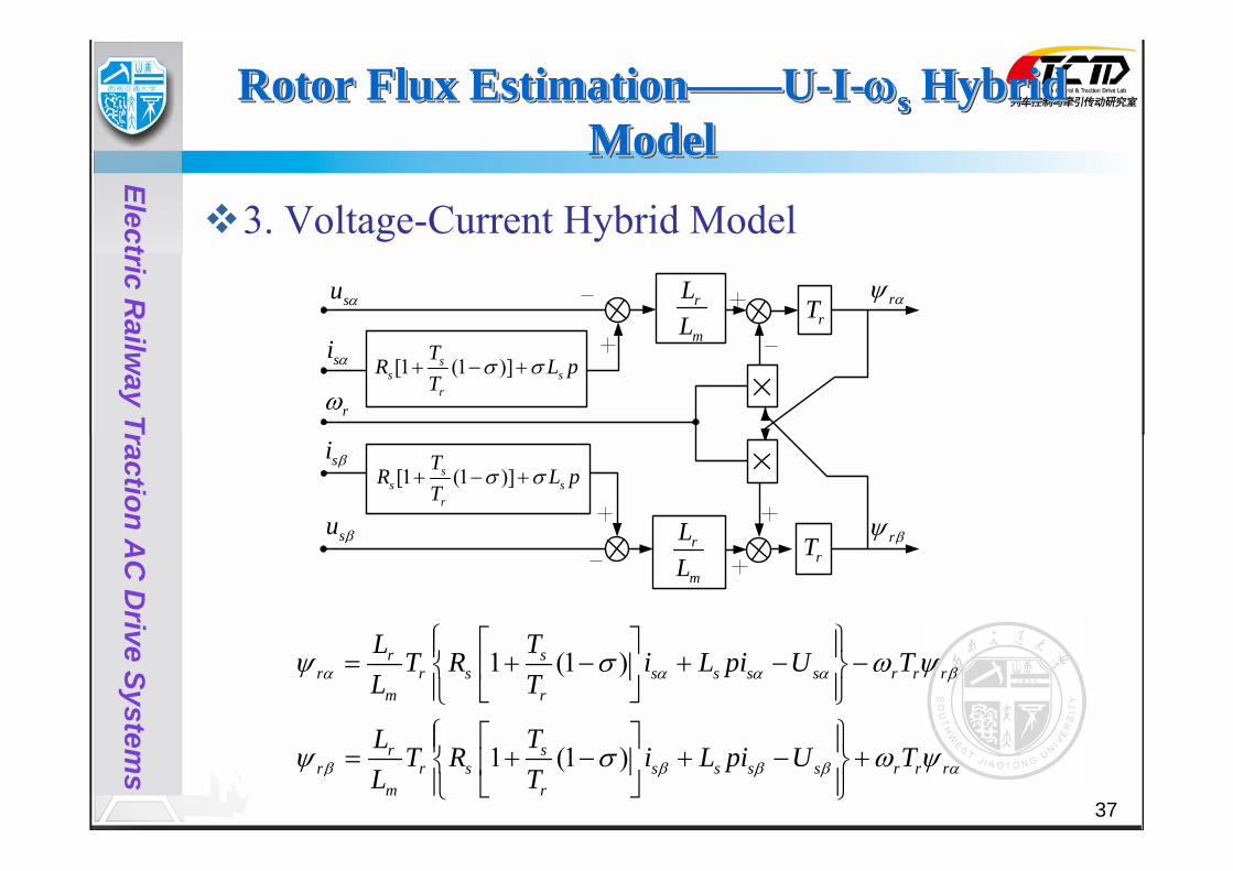
3. Voltage-Current Hybrid Model
1 (1 )
1 (1 )
srr r s s s s s r r r
m r
srr r s s s s s r r r
m r
TLT R i L pi U T
L T
TLT R i L pi U T
L T
α α α α β
β β β β α
ψ σ ω ψ
ψ σ ω ψ
⎧ ⎫⎡ ⎤⎪ ⎪= + − + − −⎨ ⎬⎢ ⎥⎪ ⎪⎣ ⎦⎩ ⎭⎧ ⎫⎡ ⎤⎪ ⎪= + − + − +⎨ ⎬⎢ ⎥⎪ ⎪⎣ ⎦⎩ ⎭
rβψ
rαψrT
rT
r
m
LL
r
m
LL
[1 (1 )]ss s
r
TR L p
Tσ σ+ − +
[1 (1 )]ss s
r
TR L p
Tσ σ+ − +
su α
su β
si β
si α
rω

38
Electric Railw
ay Traction AC
Drive System
s
Rotor Flux Estimation ——I-ωs Model in d-q Axis
Rotor Flux Estimation Rotor Flux Estimation ————II--ωωss Model in Model in dd--qq AxisAxis
4. Stator current-speed model in d-q synchronous rotating axis
(1 )sq rsl
rsd
i T pTi
ω∗
∗∗
+=
1m
r sdr
Li
T pψ =
+
s sl rω ω ω∗ ∗= +
( )s sl rdt dtϕ ω ω ω∗ ∗= = +∫ ∫
1m
r
LT p +
m
r
LT ÷ ∫
sqi∗
sdi∗ rψ
slω∗
rω
sω∗ ϕ

39
Electric Railw
ay Traction AC
Drive System
s
Indirect Vector ControlIndirect Vector ControlIndirect Vector Control
Indirect vector control is similar to direct vector control except the unit vector signals (cosθs and sinθs) are generated in a feedforward manner.
The phasor diagram on the next slide can be used to explain the basic concept of indirect vector control.

40
Electric Railw
ay Traction AC
Drive System
s
Indirect Vector Control (cont’d)Indirect Vector Control (contIndirect Vector Control (cont’’d)d)

41
Electric Railw
ay Traction AC
Drive System
s
Indirect Vector Control (cont’d)Indirect Vector Control (contIndirect Vector Control (cont’’d)d)
The α-β axes are fixed on the stator and the dr-qr axes are fixed on the rotor. The d -q axes are rotating at synchronous speed and so there is a slip difference between the rotor speed and the synchronous speed given by:
Since, , we can write:
s r slω ω ω= +
s sdtθ ω= ∫
s r slθ θ θ= +

42
Electric Railw
ay Traction AC
Drive System
s
Indirect Vector Control (cont’d)Indirect Vector Control (contIndirect Vector Control (cont’’d)d)
In order to ensure decoupling between the stator flux and the torque, the torque component of the current, isq, should be aligned with the q-axis and the stator flux component of current, isd, should be aligned with the d-axis.
We can use the d -axis and q -axis equivalent circuits of the motor (shown on the next slide) to derive control expressions.

43
Electric Railw
ay Traction AC
Drive System
s
Indirect Vector Control (cont’d)Indirect Vector Control (contIndirect Vector Control (cont’’d)d)
Fig. Dynamic d-q equivalent circuits of machine (a) q-axis circuit, (b) d- axis circuit

44
Electric Railw
ay Traction AC
Drive System
s
Indirect Vector Control (cont’d)Indirect Vector Control (contIndirect Vector Control (cont’’d)d)
The rotor circuit equations may be written as:
( ) 0rdr rd s r rq
d R idtψ ω ω ψ+ − − =
( ) 0rqr rq s r rd
dR i
dtψ
ω ω ψ+ + − =

45
Electric Railw
ay Traction AC
Drive System
s
Indirect Vector Control (cont’d)Indirect Vector Control (contIndirect Vector Control (cont’’d)d)
The rotor flux linkage equations may be written as:
These equations may be rewritten as:
rd r rd m sdL i L iψ = +
rq r rq m sqL i L iψ = +
1 mrd rd sd
r r
Li iL Lψ= −
1 mrq rq sq
r r
Li iL Lψ= −

46
Electric Railw
ay Traction AC
Drive System
s
Indirect Vector Control (cont’d)Indirect Vector Control (contIndirect Vector Control (cont’’d)d)
Combining these with the earlier equations allows us to eliminate the rotor currents which cannot be directly obtained. The resulting equations are:
where .
0rd mrrd r sd sl rq
r r
d LR R idt L Lψ ψ ω ψ+ − − =
0rq mrrq r sq sl rd
r r
d LR R idt L Lψ
ψ ω ψ+ − + =
sl s rω ω ω= −

47
Electric Railw
ay Traction AC
Drive System
s
Indirect Vector Control (cont’d)Indirect Vector Control (contIndirect Vector Control (cont’’d)d)
For decoupling control the total rotor flux needs to be aligned with the d -axis and so we want: ψrq=0 => dψrq/dt =0
If we now substitute into the previous equations, we get:
and
where has been substituted for ψrd .
rrr m sd
r
L d L iR dt
ψ ψ+ =m r
sl sqr r
L R iL
ωψ
=
rψ

48
Electric Railw
ay Traction AC
Drive System
s
Indirect Vector Control (cont’d)Indirect Vector Control (contIndirect Vector Control (cont’’d)d)
For implementing the indirect vector control strategy, we need to take these equations into consideration as well as the equation:
Note:A constant rotor flux results in the equation:
so that the rotor flux is directly proportional to isdin steady state.
r m sdL iψ =
s r slθ θ θ= +
49
Electric Railw
ay Traction AC
Drive System
s
Indirect Vector Control (cont’d)Indirect Vector Control (contIndirect Vector Control (cont’’d)d)
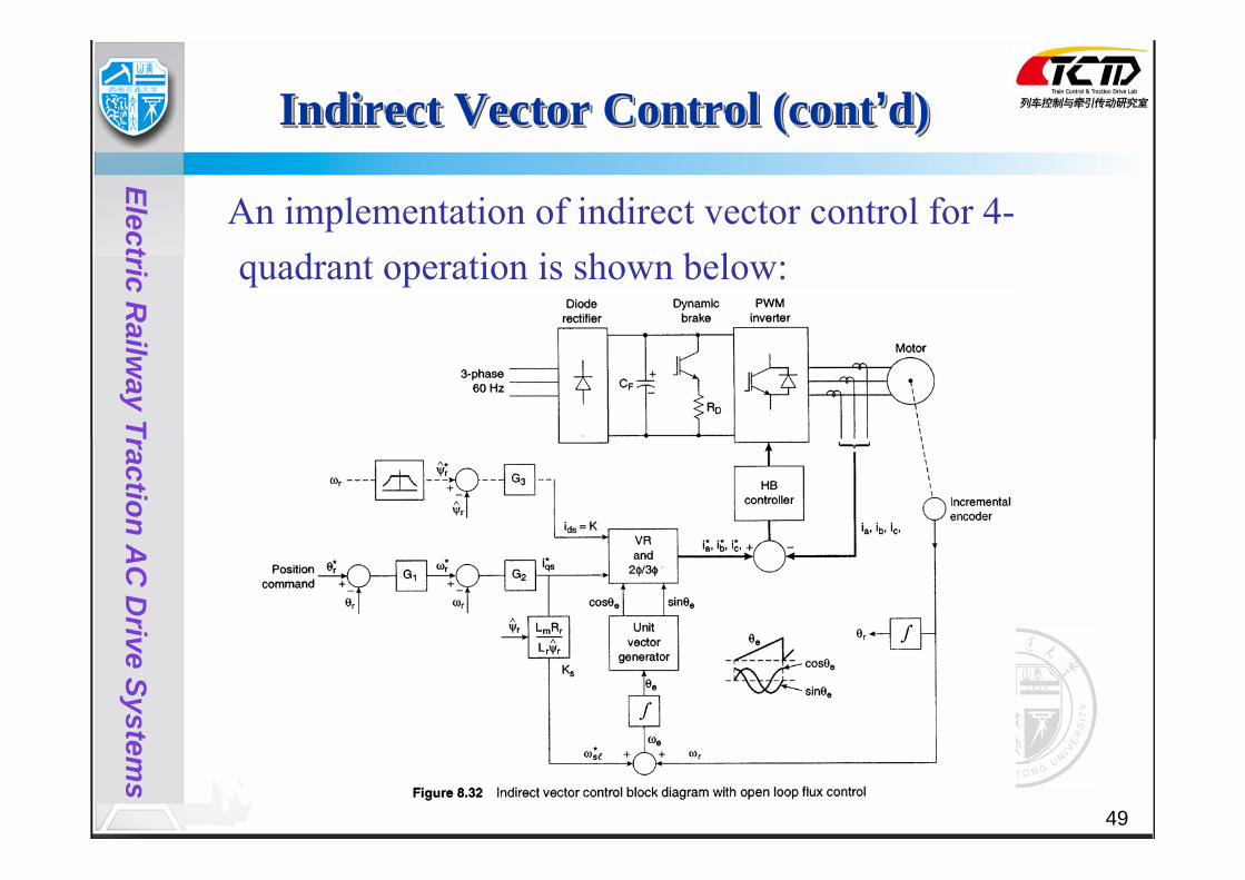
An implementation of indirect vector control for 4-quadrant operation is shown below:

50
Electric Railw
ay Traction AC
Drive System
s
Indirect Vector Control (cont’d)Indirect Vector Control (contIndirect Vector Control (cont’’d)d)
Features of this implementation:Hysteresis-band current control.
Speed control loop generates the torque component of current, isq
*.
Constant rotor flux is maintained by using the desired isd
*.
The slip frequency ωsl* is generated from the
desired isq*.

51
Electric Railw
ay Traction AC
Drive System
s
Indirect Vector Control (cont’d)Indirect Vector Control (contIndirect Vector Control (cont’’d)d)
Slip gain Ks is given by:
ωs and θs are given by:
and
The incremental encoder is necessary for indirect vector control because the slip signal locates the rotor pole position with respect to the dr axis in a feedforward manner.
*
*sl m r
ssq rr
L RKi Lω
ψ= =
*s sl rω ω ω= + sdtθ ω= ∫

52
Electric Railw
ay Traction AC
Drive System
s
Indirect Vector Control (cont’d)Indirect Vector Control (contIndirect Vector Control (cont’’d)d)
If isq*<0 for negative torque, phasor isq is reversed and
ωsl (and θsl) will be negative. The speed control range can be extended into the field weakening region by incorporating the dotted line part of the implementation (see figure below).Note: Closed loop flux control is now required.

53
Electric Railw
ay Traction AC
Drive System
s
Indirect Vector Control (cont’d)Indirect Vector Control (contIndirect Vector Control (cont’’d)d)
Harmonic content of hysteresis-band current control is not optimum. Also, at higher speeds the current controller will saturate in part of the cycle because of the high back emf.
Synchronous current control can be used to overcome these problems. See Bose text, pp. 372-374 for details.

54
Electric Railw
ay Traction AC
Drive System
s
Indirect Vector Control (cont’d)Indirect Vector Control (contIndirect Vector Control (cont’’d)d)
A DC motor-like electromechanical model can be derived for an ideal vector-controlled drive using the following equations:
32 2
mre sq
r
LPT iLψ⎛ ⎞= ⎜ ⎟
⎝ ⎠
rrr m sd
r
L d L iR dt
ψ ψ+ =
2 re L
dT T JP dt
ω⎛ ⎞− = ⎜ ⎟⎝ ⎠

55
Electric Railw
ay Traction AC
Drive System
s
Indirect Vector Control (cont’d)Indirect Vector Control (contIndirect Vector Control (cont’’d)d)
A transfer function block diagram is shown below:
Note: The torque Te responds instantly but the flux has first order delay (with time constant =Lr/Rr).

56
Electric Railw
ay Traction AC
Drive System
s
Indirect Vector Control (cont’d)Indirect Vector Control (contIndirect Vector Control (cont’’d)d)
The physical principle of vector control can be explained more clearly with the help of the below d-q equivalent circuits:

57
Electric Railw
ay Traction AC
Drive System
s
Indirect Vector Control (cont’d)Indirect Vector Control (contIndirect Vector Control (cont’’d)d)
Since isd and isq are being controlled, we can ideally ignore the stator-side parameters. With ψrq=0 under all conditions, the emf source on the rotor side d -circuit ωslψrq=0. This means that in steady state isd flows only through the magnetizing inductance, Lm, but in the transient case, is shared by the rotor circuit whose time constant = Llr/Rr.

58
Electric Railw
ay Traction AC
Drive System
s
Indirect Vector Control (cont’d)Indirect Vector Control (contIndirect Vector Control (cont’’d)d)
In the q -circuit when torque is controlled by isq the emf ωslψrd
changes instantaneously (because ).
Since ψrq=0, this emf causes a current (Lm/Lr)isq to flow through the rotor resistor Rr. If Llr is neglected and flux is constant, isd is seen to only flow through Lm and isq only flows through the rotor side, as desired.
/sl rd m r sq rL R i Lω ψ =
rψ

59
Electric Railw
ay Traction AC
Drive System
s
Indirect Vector Control (cont’d)Indirect Vector Control (contIndirect Vector Control (cont’’d)d)
A serious issue with respect to indirect vector control is that of slip gain detuning. This is due primarily to variation in rotor resistance. This effect is illustrated below where Rr=actual rotor resistance and
= estimated rotor resistance. rR

60
Electric Railw
ay Traction AC
Drive System
s
Indirect Vector Control (cont’d)Indirect Vector Control (contIndirect Vector Control (cont’’d)d)
Continuous on-line tuning of Ks is very complex and computationally intensive. However, two methods, one based on extended Kalman filtering (EKF) for parameter estimation and a second one based on a model referencing adaptive controller (MRAC) approach are good options. The EKF method will be considered later when studying sensorless vector control but the MRAC method is described next.
61
Electric Railw
ay Traction AC
Drive System
s
Indirect Vector Control (cont’d)Indirect Vector Control (contIndirect Vector Control (cont’’d)d)
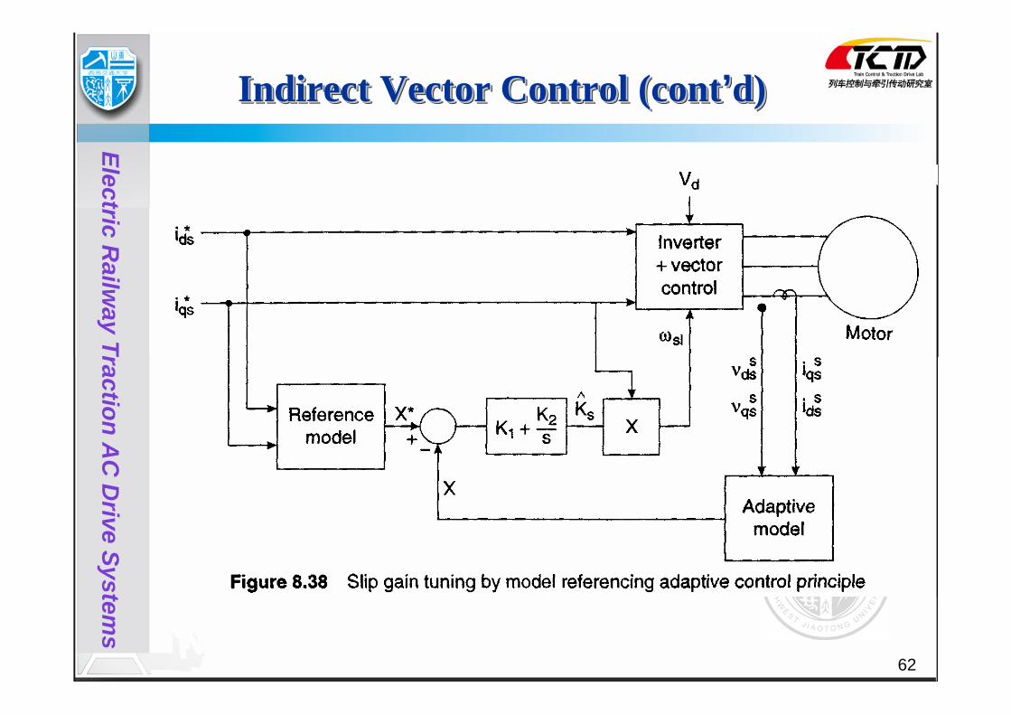
In the MRAC approach a reference model output signal X* that satisfies the tuned vector control condition is usually a function of isd
* and isq*, motor inductances,
and operating frequency. The adaptive model X is estimated based on motor feedback voltages and currents as shown in the next slide. X is compared to X* an the resulting error used to estimate the slip gain through a P-I compensator. Slip gain tuning is achieved when X=X*.
sK
62
Electric Railw
ay Traction AC
Drive System
s
Indirect Vector Control (cont’d)Indirect Vector Control (contIndirect Vector Control (cont’’d)d)
63
Electric Railw
ay Traction AC
Drive System
s
Indirect Vector Control (cont’d)Indirect Vector Control (contIndirect Vector Control (cont’’d)d)
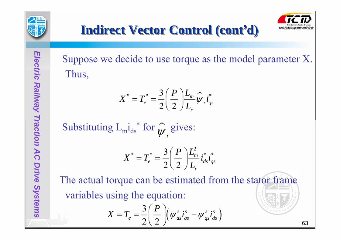
Suppose we decide to use torque as the model parameter X. Thus,
Substituting Lmids* for gives:
The actual torque can be estimated from the stator frame variables using the equation:
* * *32 2
me qsr
r
LPX T iLψ⎛ ⎞= = ⎜ ⎟
⎝ ⎠
rψ2
* * * *32 2
me ds qs
r
LPX T i iL
⎛ ⎞= = ⎜ ⎟⎝ ⎠
( )32 2
s s s se ds qs qs ds
PX T i iψ ψ⎛ ⎞= = −⎜ ⎟⎝ ⎠

64
Electric Railw
ay Traction AC
Drive System
s
Indirect Vector Control (cont’d)Indirect Vector Control (contIndirect Vector Control (cont’’d)d)
Note: Lm and Lr parameter variations affect the estimation accuracy of X* and at low speeds, the stator resistance Rs affects the estimation accuracy of X.

65
Electric Railw
ay Traction AC
Drive System
s
Stator Flux-Oriented Vector ControlStator FluxStator Flux--Oriented Vector ControlOriented Vector Control
Until now we have only considered rotor flux-oriented vector control. Airgap flux or stator flux-oriented vector control is also possible but at a cost of a coupling effect that requires decoupling compensation. See Bose text pp. 381-384 for details.

66
Electric Railw
ay Traction AC
Drive System
s
Vector Control of Current-FedInverter Drive
Vector Control of CurrentVector Control of Current--FedFedInverter DriveInverter Drive
Vector control can also be extended to current-fed drives as illustrated below:

67
Electric Railw
ay Traction AC
Drive System
s
Vector Control of Current-Fed Inverter Drive (cont’d)
Vector Control of CurrentVector Control of Current--Fed Fed Inverter Drive (contInverter Drive (cont’’d)d)
Drive operates with regulated rotor flux and the speed control loop is the outer loop. The speed loop generates the torque command Te
* which is then divided by K to generate isq
*. The flux loop generates isd*.
is used to control the firing angle of the phase controlled rectifier through a feedback loop. The inverter frequency is controlled by a phase-locked loop (PLL) so that the stator current, , is maintained at the desired torque angle with respect to the rotor flux.
rψ
sI
sI

68
Electric Railw
ay Traction AC
Drive System
s
Case: CRH2 EMU Vector Control SystemCase: CRH2 EMU Vector Control SystemCase: CRH2 EMU Vector Control SystemConstant
Speed Controller
Torque Command Calculation
Normal/Constant Speed
Rotor FluxCommand Calculation
3s/2r
Idling Stop Adhesion Control
Vector Control
operating
FF VoltageCalculat
ion
Modulation Index
Caculation
Phase Angle
Caculation
Rotor Resistor Compensation
integral
Beat-less Controller
Control Mode switching
Switching
PI
Modulation Index m
Angle
Phase Angle of Voltage
Rotor Flux Command
Torque Command
Rotor Flux Command Scheduling Table
IPLS
dU
(8)
(9)
(13)
θ
∗0eT
fbeat-less
dsr
PI
PI
L
H
L
H
0
0
L
H ∗slf
slff
FINV
(4)
L
H
∗0eT
(3)
(1)
(2)
(15)
0(10)
∗rψ
(5) (6)
(11)
θ
(12)
(14)
(7)
rf
γ
aibici
iqs
fsl**
iqs*
ids*
Eqs*
Eds*
Uds**
Uqs**
Uqs*
Uds*
ids
Eds*
fs
Udc
fs
fs
friqs

69
Electric Railw
ay Traction AC
Drive System
s
(1)Torque Command Design((11))Torque Command DesignTorque Command Design

70
Electric Railw
ay Traction AC
Drive System
s
(2)Constant Speed Controller((22))Constant Speed ControllerConstant Speed Controller

71
Electric Railw
ay Traction AC
Drive System
s
(3)Rotor flux Command Design((33))Rotor flux Command DesignRotor flux Command Design

72
Electric Railw
ay Traction AC
Drive System
s
(5)Vector Control Calculation Design((55))Vector Control Calculation DesignVector Control Calculation Design
**
*
**
e rqs
p m r
rds
m
T Lin L
iL
ψ
ψ
=
=
*
*2
qssl
rds
r
if L i
Rπ
=

73
Electric Railw
ay Traction AC
Drive System
s
(6)Voltage feed-forward (FF) Compensation((66))Voltage feedVoltage feed--forward (FF) Compensationforward (FF) Compensation
ds s ds ds s qs
qs s qs qs s ds
du R idtdu R idt
ψ ωψ
ψ ωψ
⎧ = + −⎪⎪⎨⎪ = + +⎪⎩
* * *
* * *
2
= +
1
ds s ds s s qs
qs s qs s s ds
m
s r
E R i L i
E R i L i
LL L
ω σ
ω
σ
= −
−Note: =
0dr r r dr m ds
qr r qr m qs
L i L iL i L i
ψ ψψ
= = +⎧⎪⎨ = = +⎪⎩
74
Electric Railw
ay Traction AC
Drive System
s
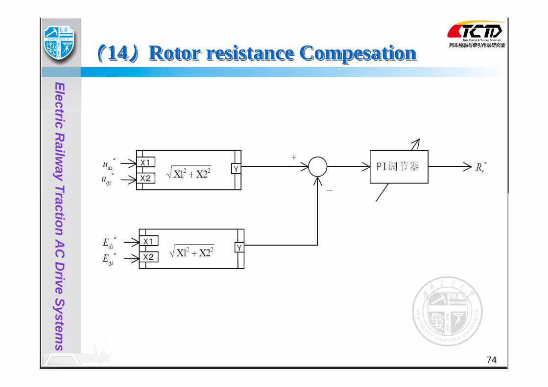
(14)Rotor resistance Compesation((1414))Rotor resistance Rotor resistance CompesationCompesation

75
Electric Railw
ay Traction AC
Drive System
s
Simulation Results of Railway traction AC Drives system Simulation Results of Railway traction AC Drives system Simulation Results of Railway traction AC Drives system
Traction Characteristic
Stator flux trajectory
Stator phase voltage
Output Power
Stator current

76
Electric Railw
ay Traction AC
Drive System
s
Thanks for your listening in my class!
Wish you have a nice day for studying and living in China!