Chapter11 addressing
89
INSTRUCTION SETS: ADDRESSING MODES AND FORMATS CHAPTER 11 MINGOY GAFFUD DANIEL
-
Upload
christian-james-mingoy -
Category
Technology
-
view
254 -
download
0
Transcript of Chapter11 addressing

INSTRUCTION SETS:ADDRESSING
MODES
AND
FORMATS
CH
APTE
R 1
1
MINGOY GAFFUD DANIEL

ADDRESSING

ADDRESSING
IMMEDIATE
DIRECT
INDIRECT
REGISTER
REGISTER INDIRECT
DISPLACEMENT
STACK
ADDRESSING
IMMEDIATE
the simplest form of addressing in which the
operand value is present in the instruction
can be used to define and use constants or
set initial values of variable
the no. will be stored in twos complement
form; the left-most bit of the operand field is
used as a sign bit.
ADDRESSING
IMMEDIATE
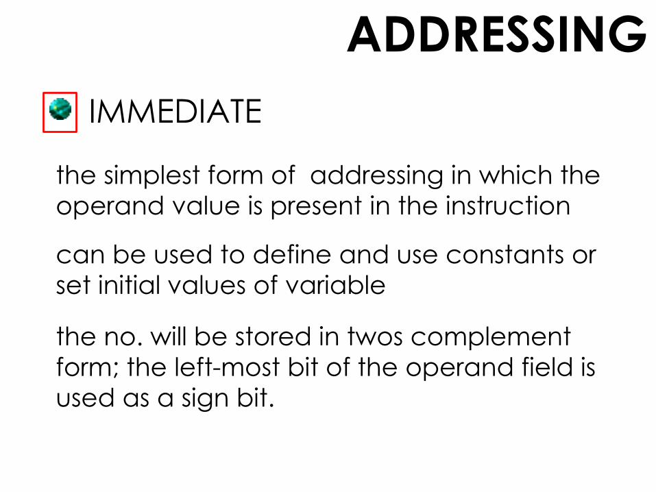
When the operand is loaded into a data register, the
sign bit is extended to the left data word size.
No memory reference other than the instruction
fetch is required to obtain the operand, thus saving
one memory or cache cycle in the instruction cycle.
The size of the number is restricted to the size
of the address field, which, in most instruction
sets, is small compared with the word length.
ADDRESSING
IMMEDIATE
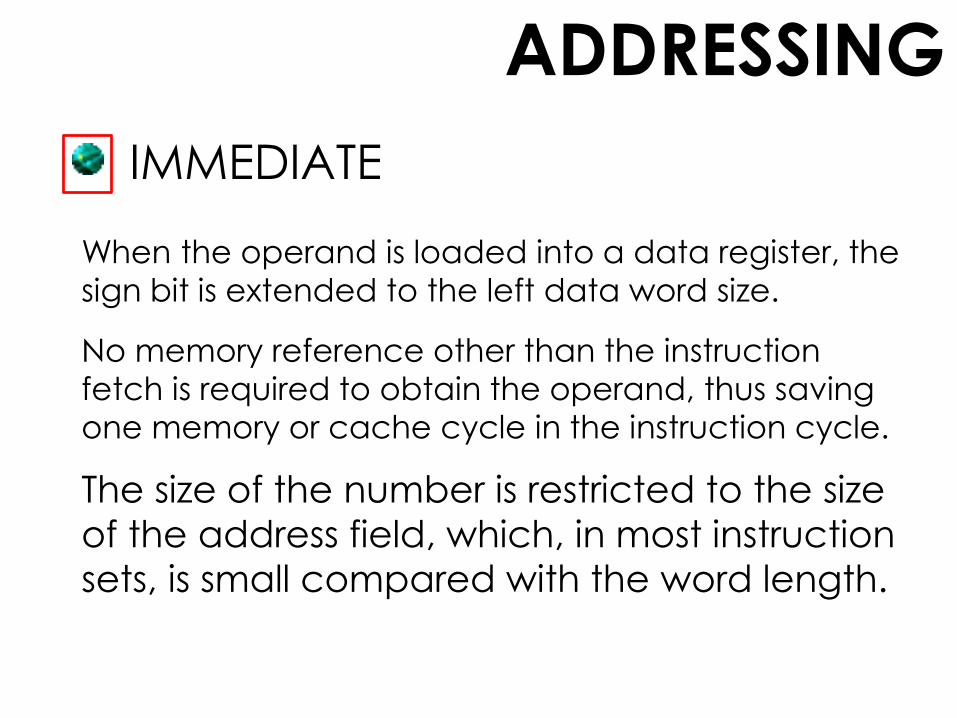
A = contents of an address
field in the instruction
R = contents of an address
field in the instruction that
refers to a register
EA = actual (effective)
address of the location
containing the referenced
operand
(X) = contents of
memory location X or
register X
OPERAND = A LEGEND:

ADDRESSING
DIRECT
a very simple form of addressing in which the address
field contains the effective address of the operand
common in earlier generations of computers but is
not on contemporary architectures
requires only one memory reference and no special
calculation
it provides only a limited address space

ADDRESSING
DIRECTEA = A
A = contents of an address
field in the instruction
R = contents of an address
field in the instruction that
refers to a register
EA = actual (effective)
address of the location
containing the referenced
operand
(X) = contents of
memory location X or
register X
LEGEND:
ADDRESSING
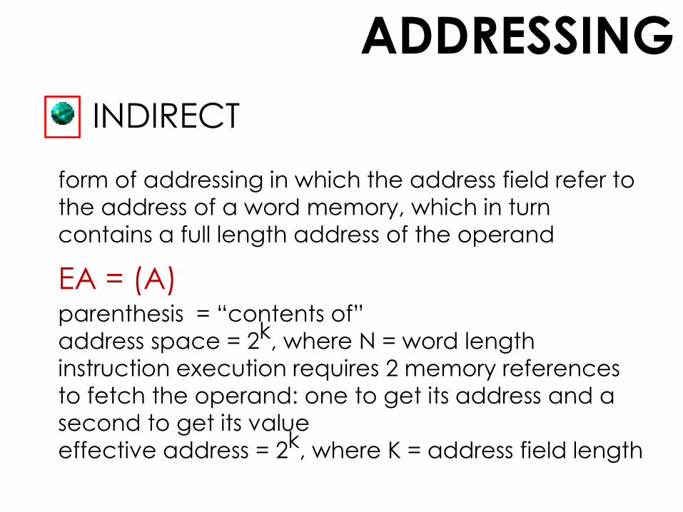
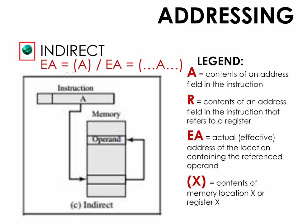
INDIRECT
form of addressing in which the address field refer to
the address of a word memory, which in turn
contains a full length address of the operand
EA = (A)parenthesis = “contents of”
address space = 2k, where N = word length
instruction execution requires 2 memory references
to fetch the operand: one to get its address and a
second to get its value
effective address = 2k, where K = address field length
ADDRESSING
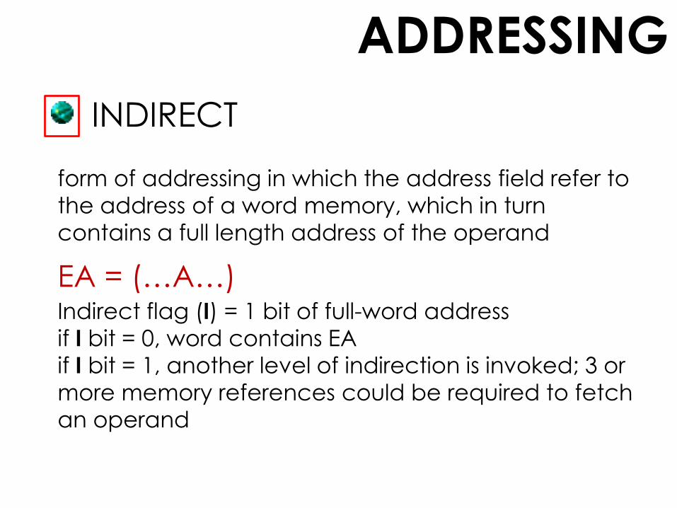
INDIRECT
form of addressing in which the address field refer to
the address of a word memory, which in turn
contains a full length address of the operand
EA = (…A…)Indirect flag (I) = 1 bit of full-word address
if I bit = 0, word contains EA
if I bit = 1, another level of indirection is invoked; 3 or
more memory references could be required to fetch
an operand
ADDRESSING
INDIRECT
A = contents of an address
field in the instruction
R = contents of an address
field in the instruction that
refers to a register
EA = actual (effective)
address of the location
containing the referenced
operand
(X) = contents of
memory location X or
register X
EA = (A) / EA = (…A…) LEGEND:

ADDRESSING
REGISTER
similar with direct addressing but the only difference
is that the address field refers to a register rather than
a main memory address
contents of a register address (N) = intended address R(N)
Operand value is in the intended address
Only a small address field is needed in the instruction.
No time-consuming memory references are required.

ADDRESSING
REGISTER
A = contents of an address
field in the instruction
R = contents of an address
field in the instruction that
refers to a register
EA = actual (effective)
address of the location
containing the referenced
operand
(X) = contents of
memory location X or
register X
EA = R LEGEND:
ADDRESSING
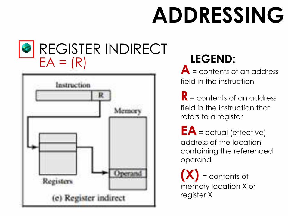
REGISTER INDIRECT
analogous to indirect addressing but the difference is
that whether the address field refers to a memory
location or a register
address space limitation (limited range of addresses)
of the address field is overcome by having that field
refer to a word-length location containing an
address
uses one less memory reference than indirect
addressing
ADDRESSING
REGISTER INDIRECT
A = contents of an address
field in the instruction
R = contents of an address
field in the instruction that
refers to a register
EA = actual (effective)
address of the location
containing the referenced
operand
(X) = contents of
memory location X or
register X
EA = (R) LEGEND:

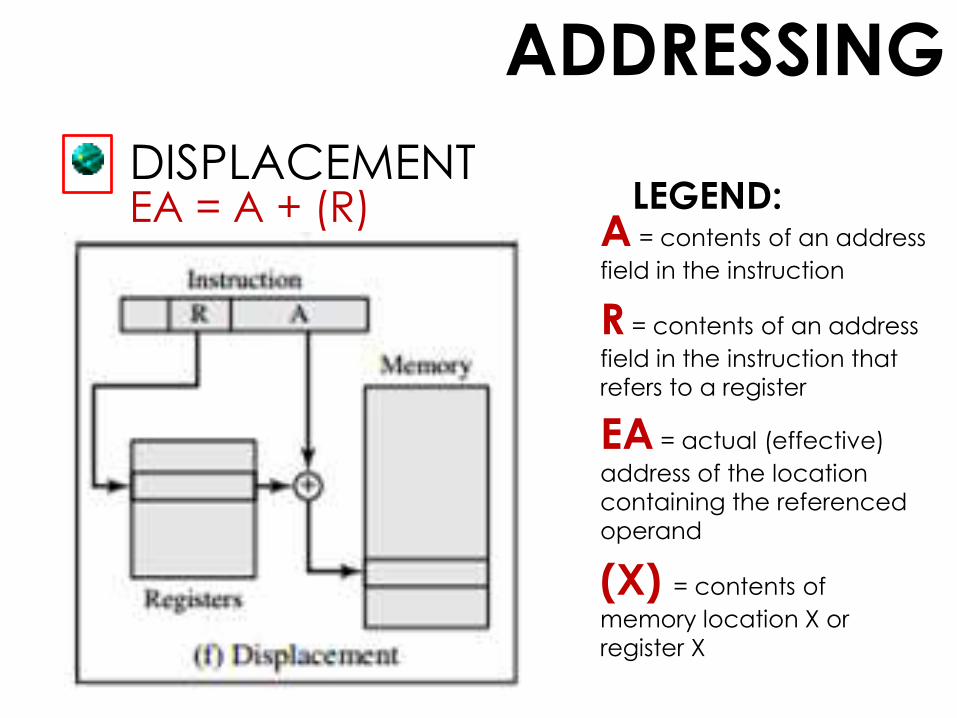
ADDRESSING
DISPLACEMENT
a very powerful mode of addressing combines the
capabilities of direct addressing and register indirect
addressing
known by a variety of names depending on the
context of its use, but the basic mechanism is the
same
requires that the instruction have two address fields,
at least one of which is explicit
ADDRESSING
DISPLACEMENT
A = contents of an address
field in the instruction
R = contents of an address
field in the instruction that
refers to a register
EA = actual (effective)
address of the location
containing the referenced
operand
(X) = contents of
memory location X or
register X
EA = A + (R) LEGEND:
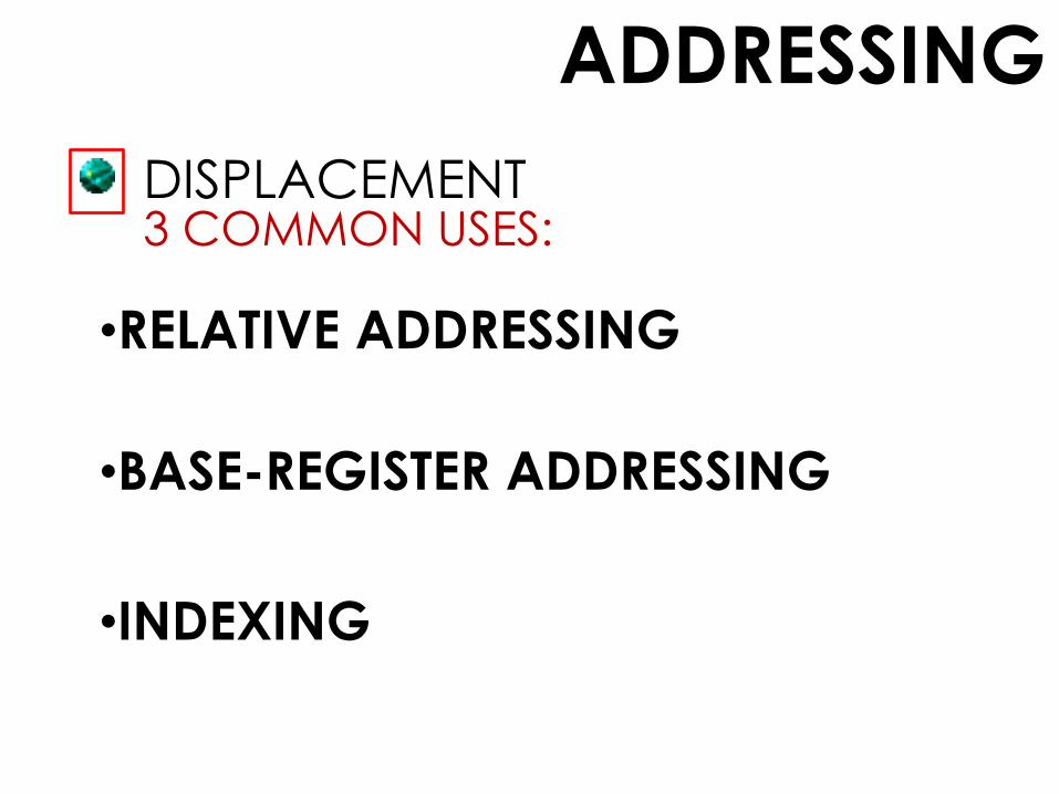
ADDRESSING
DISPLACEMENT3 COMMON USES:
•RELATIVE ADDRESSING
•BASE-REGISTER ADDRESSING
•INDEXING
ADDRESSING
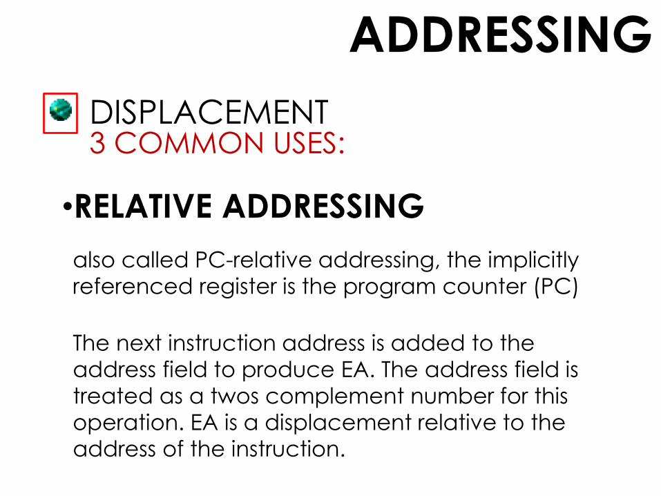
DISPLACEMENT3 COMMON USES:
•RELATIVE ADDRESSING
also called PC-relative addressing, the implicitly
referenced register is the program counter (PC)
The next instruction address is added to the
address field to produce EA. The address field is
treated as a twos complement number for this
operation. EA is a displacement relative to the
address of the instruction.

ADDRESSING
DISPLACEMENT3 COMMON USES:
•BASE-REGISTER ADDRESSING
The referenced register contains a main memory address
and the address field contains a displacement (usually an
unsigned integer representation)from that address.
The register reference may be explicit or implicit.
also exploits the locality of memory references
convenient means of implementing segmentation
ADDRESSING
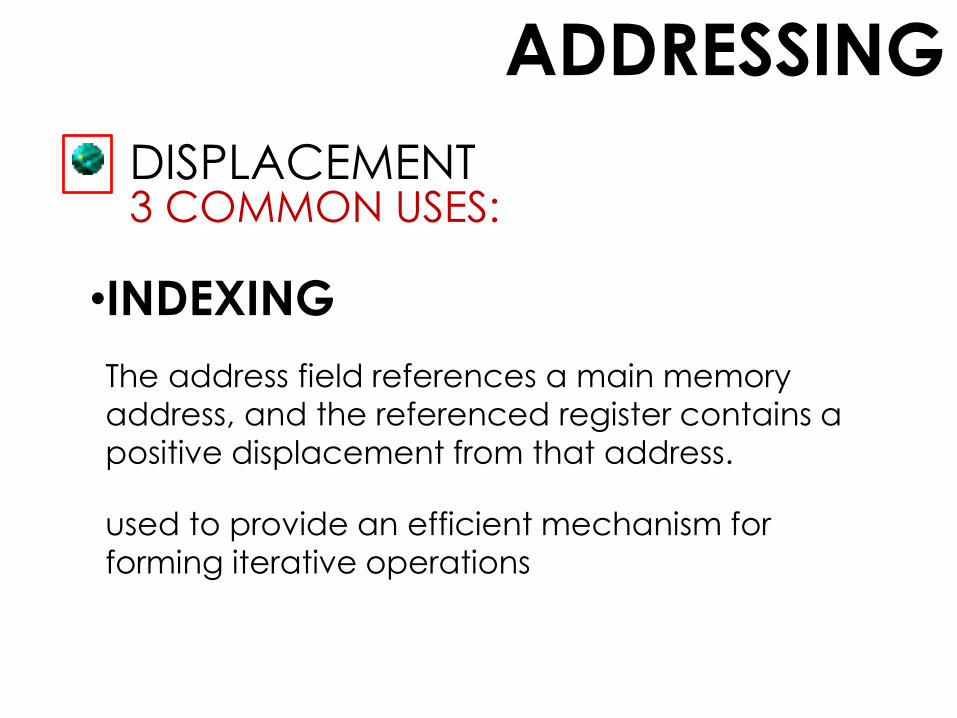
DISPLACEMENT3 COMMON USES:
•INDEXING
The address field references a main memory
address, and the referenced register contains a
positive displacement from that address.
used to provide an efficient mechanism for
forming iterative operations

ADDRESSING
STACK
Stack is a linear array of locations; reserved block of
locations.
A form of implied addressing, the machine
instructions need not include a memory reference
but implicitly operate on the top of the stack.
Sometimes referred to as a pushdown list or last-in-
first-out queue

ADDRESSING
STACK
A = contents of an address
field in the instruction
R = contents of an address
field in the instruction that
refers to a register
EA = actual (effective)
address of the location
containing the referenced
operand
(X) = contents of
memory location X or
register X
LEGEND:EA = TOP OF STACK

ADDRESSING MODESx86 and ARM
ADDRESSING MODESx86
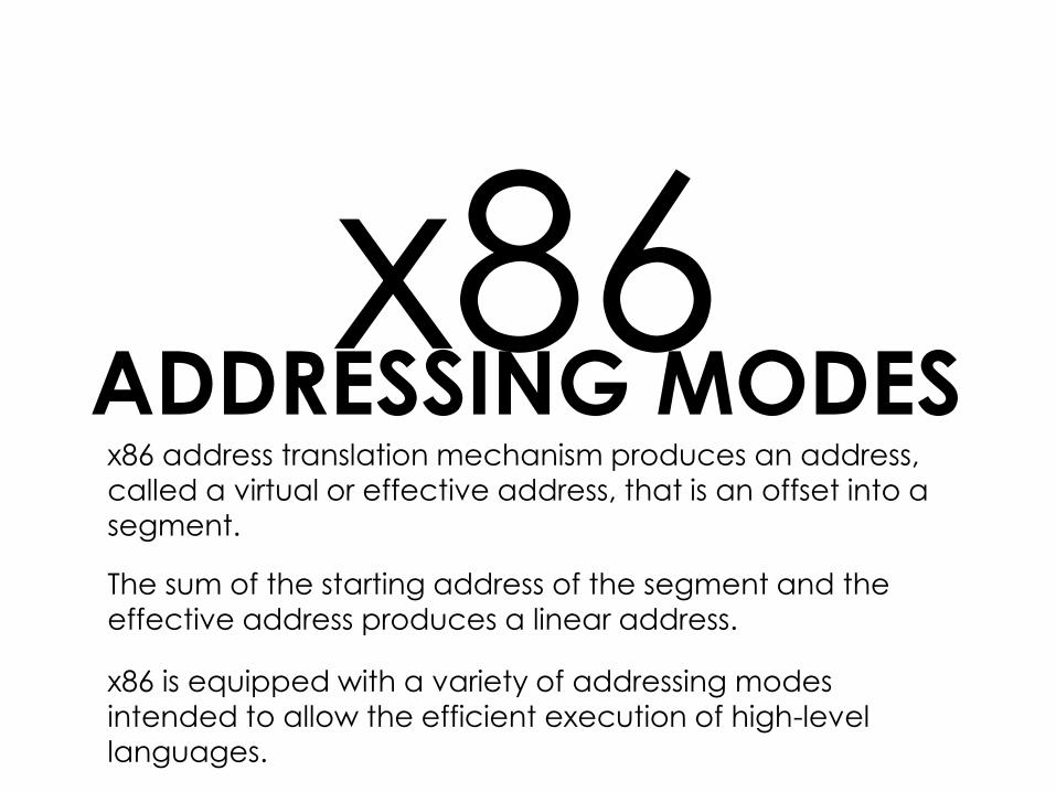
x86 address translation mechanism produces an address,
called a virtual or effective address, that is an offset into a
segment.
The sum of the starting address of the segment and the
effective address produces a linear address.
x86 is equipped with a variety of addressing modes
intended to allow the efficient execution of high-level
languages.

MODESx86 ADDRESSING
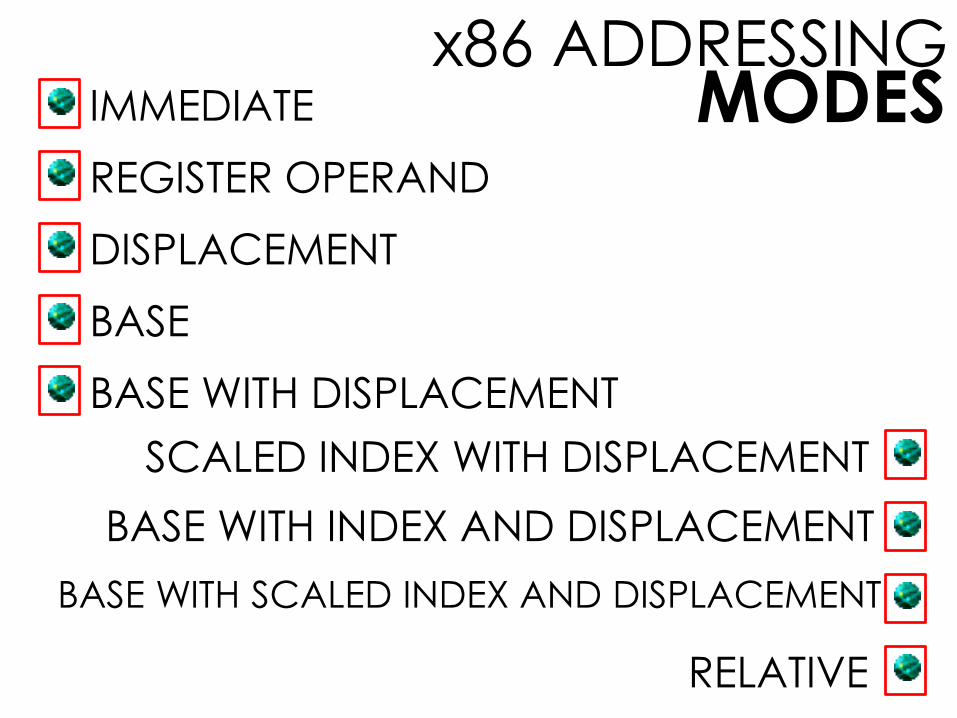
MODESx86 ADDRESSING
REGISTER OPERAND
DISPLACEMENT
BASE
BASE WITH DISPLACEMENT
SCALED INDEX WITH DISPLACEMENT
BASE WITH INDEX AND DISPLACEMENT
BASE WITH SCALED INDEX AND DISPLACEMENT
IMMEDIATE
RELATIVE

MODESx86 ADDRESSING
IMMEDIATE
operand is included in the instruction
operand can be a byte, word, or
doubleword of data
LEGEND:
OPERAND = A

MODESx86 ADDRESSING
REGISTER OPERAND
operand is located in a register
operand can be one of the 32-bit or 16-
bit or 8-bit general registers
LEGEND:
LA = R

MODESx86 ADDRESSING
DISPLACEMENT
operand’s offset is contained as part of the
instruction as an 8-, or 16-, or 32-bit displacement
displacement value can be as long as 32
bits, making for a 6-byte instruction
LEGEND:
LA = (SR) + A

MODESx86 ADDRESSING
BASE
specifies that one of the 8-, 16-, or 32-bit
registers contains the effective address
equivalent to Register Indirect Addressing
LEGEND:
LA = (SR) + (B)

MODESx86 ADDRESSING
BASE WITH DISPLACEMENT
instruction includes a displacement to be
added to a base register, which may be
any of the general-purpose registers
LEGEND:
LA = (SR) + (B) + A
MODESx86 ADDRESSING
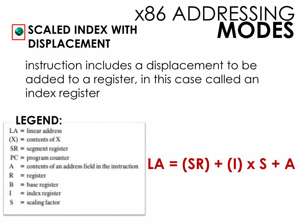
SCALED INDEX WITH
DISPLACEMENT
LEGEND:
instruction includes a displacement to be
added to a register, in this case called an
index register
LA = (SR) + (I) x S + A
MODESx86 ADDRESSING
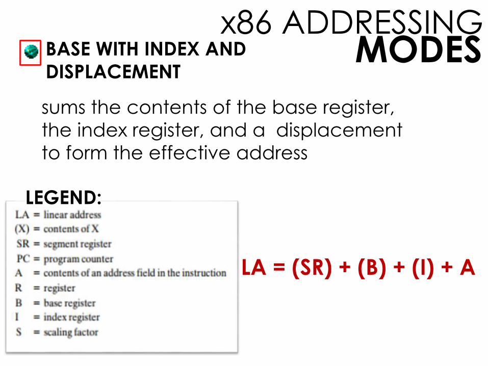
BASE WITH INDEX AND
DISPLACEMENT
LEGEND:
sums the contents of the base register,
the index register, and a displacement
to form the effective address
LA = (SR) + (B) + (I) + A

MODESx86 ADDRESSING
BASE SCALED INDEX WITH
DISPLACEMENT
LEGEND:
sums the contents of the index register
multiplied by a scaling factor, the contents
of the base register, and the displacement
LA = (SR) + (I) x S + (B) + A

MODESx86 ADDRESSING
RELATIVE
can be used in transfer-of-control instructions
displacement is added to the value of the
program counter, which points to the next
instructionLEGEND:
LA = (PC) + A

ADDRESSING MODESARM
a RISC machine, unlike a CISC machine, uses a
simple and relatively straightforward set of
addressing modes
These modes are most conveniently classified
with respect to the type of instruction.
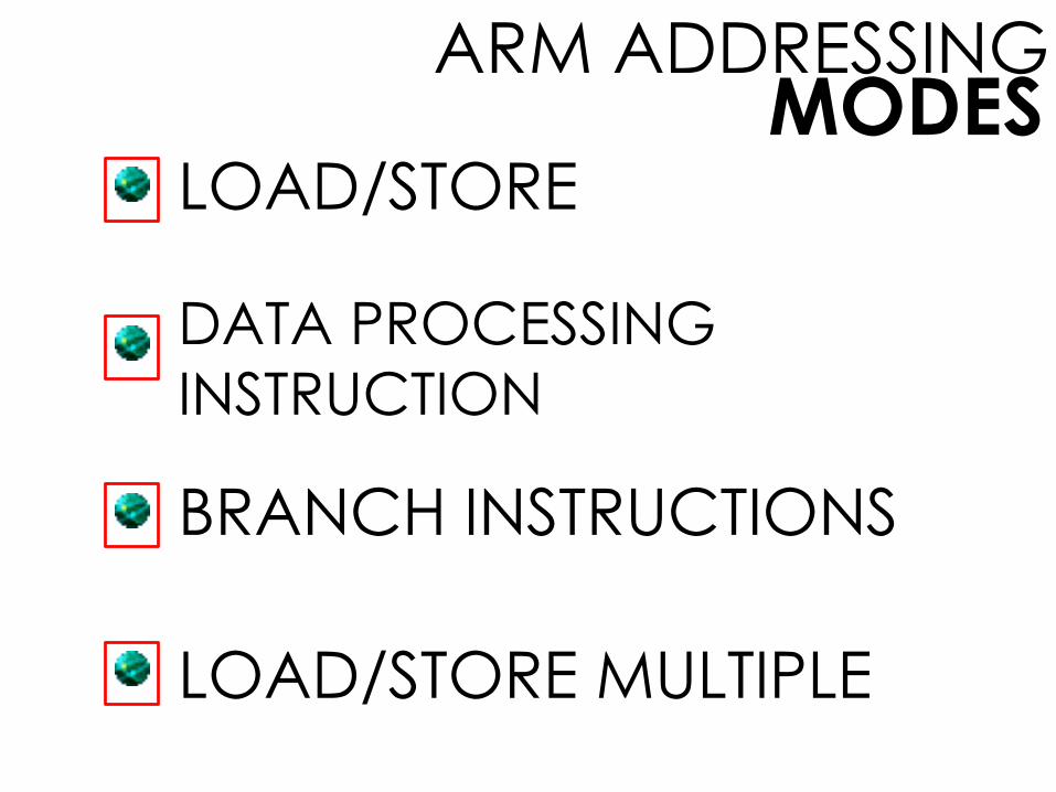
MODESARM ADDRESSING
LOAD/STORE
DATA PROCESSING
INSTRUCTION
BRANCH INSTRUCTIONS
LOAD/STORE MULTIPLE
MODESARM ADDRESSING
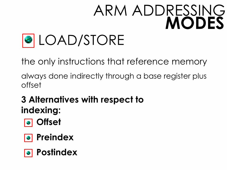
LOAD/STORE
the only instructions that reference memory
always done indirectly through a base register plus
offset
3 Alternatives with respect to
indexing:
Offset
Preindex
Postindex

MODESARM ADDRESSING
3 Alternatives with respect to
indexing:
Offset
offset value is added to or subtracted from the
value in the base register to form the memory
address

MODESARM ADDRESSING
3 Alternatives with respect to
indexing:
Preindex
the base register value is incremented or
decremented by the offset value

MODESARM ADDRESSING
3 Alternatives with respect to
indexing:
Postindex
memory address = base register value
An offset is added to or subtracted from the base register
value and the result is written back to the base register
MODESARM ADDRESSING
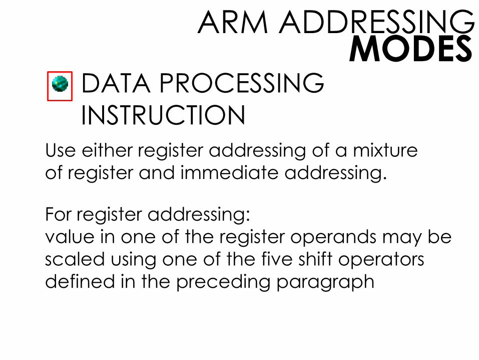
DATA PROCESSING
INSTRUCTION
Use either register addressing of a mixture
of register and immediate addressing.
For register addressing:
value in one of the register operands may be
scaled using one of the five shift operators
defined in the preceding paragraph
MODESARM ADDRESSING
BRANCH INSTRUCTIONS
only form of addressing: immediate addressing
contain 24-bit value
For address calculation, this value is shifted
left 2 bits, so that the address is on a word
boundary.
Effective address range is ±32 MB from the
program counter.

MODESARM ADDRESSING
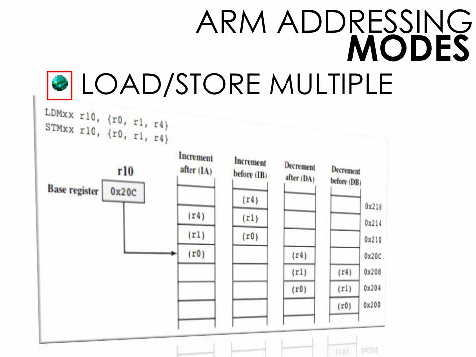
LOAD/STORE MULTIPLE
Load Multiple load a subset (possibly all) of the
general-purpose registers from the memory.
Store Multiple store a subset (possibly all) of the
general-purpose registers to memory.
produce a sequential range of memory addresses
lowest numbered register = lowest memory addresshighest numbered register = highest memory address
useful for block loads or stores, stack operations, and
procedure exit sequences
MODESARM ADDRESSING
LOAD/STORE MULTIPLE

INSTRUCTION
FORMATSdefines the layout of the bits of an instruction, in
terms of its constituent fields
must include an opcode and, implicitly or
explicitly, zero or more operands.
FORMATSINSTRUCTION
ALLOCATION OF BITS
PDP-8
PDP-10
VARIABLE-LENGTH INSTRUCTIONS
INSTRUCTION LENGTH
PDP-11
VAX
FORMATSINSTRUCTION
INSTRUCTION LENGTH
most basic design to be faced
This decision affects, and is affected by, memory
size, memory organization, bus structure,
processor complexity, and processor speed.
also determines the richness and flexibility of the
machine as seen by the assembly-language
programmer

FORMATSINSTRUCTION
ALLOCATION OF BITS
an equally difficult issue in deciding the length of
the instruction format
For a given instruction length, there is clearly a
trade-off between the number of opcodes and
the power of the addressing capability. More
opcodes obviously mean more bits in the opcode
field.
For an instruction format of a given length, this
reduces the no. of bits available for addressing.
FORMATSINSTRUCTION
PDP-8
one of the simplest instruction designs for a
general-purpose computer by BELL78b
uses 12-bit instructions and operates on 12-bit
words
There is a single general-purpose register, the
accumulator.
supports indirect and displacement addressing,
and indexing
FORMATSINSTRUCTION
PDP-10
a sharp contrast to the instruction set of the PDP-8
designed to be a large-scale time-shared system,
with an emphasis on making the system easy to
program, even if additional hardware expense
was involved
Design Principles by BELL78c:
Orthogonality
Completeness
Direct Addressing
FORMATSINSTRUCTION
PDP-10Design Principles by BELL78c:
Orthogonality
a principle by which two variables are
independent of each other
indicates that other elements of an
instruction are independent of the
opcode
FORMATSINSTRUCTION
PDP-10Design Principles by BELL78c:
Completeness
Each arithmetic data type (integer,
fixed-point, floating-point) should
have a complete and identical set of
operations.
FORMATSINSTRUCTION
PDP-10Design Principles by BELL78c:
Direct Addressing
Base plus displacement addressing,
which places a memory organization
burden on the programmer, was
avoided in favor of direct addressing.

FORMATSINSTRUCTION
FACTORS IN USING
ADDRESSING BITS:
Number of addressing modes
Number of operands
Register versus memory
Number of register sets
Address range
Address granularity

FORMATSINSTRUCTION
FACTORS IN USING
ADDRESSING BITS:
Number of addressing modes
Sometimes an addressing mode can be indicated implicitly. For example, certain
opcodes might always call for indexing. In
other cases, the addressing modes must
be explicit, and one or more mode bits will
be needed.

FORMATSINSTRUCTION
FACTORS IN USING
ADDRESSING BITS:
Number of operands
We have seen that fewer addresses can make for
longer, more awkward programs (e.g., Figure
10.3). Typical instructions on today’s machines
provide for two operands. Each operand address
in the instruction might require its own mode
indicator, or the use of a mode indicator could
be limited to just one of the address fields.

FORMATSINSTRUCTION
FACTORS IN USING
ADDRESSING BITS:
Register versus memory
A machine must have registers so that data can be brought
into the processor for processing. With a single user-visible register (usually called the accumulator), one operand
address is implicit and consumes no instruction bits.
However, single-register programming is awkward and
requires many instructions. Even with multiple registers, only
a few bits are needed to specify the register. The more that
registers can be used for operand references, the fewer bits are needed. A number of studies indicate that a total of 8
to 32 user-visible registers is desirable [LUND77, HUCK83].
Most contemporary architectures have at least 32 registers.
FORMATSINSTRUCTION
FACTORS IN USING
ADDRESSING BITS:
Number of register sets
Most contemporary machines have one set of general-purpose registers, with typically 32 or more registers in the set. These registers can be used to store data and can be
used to store addresses for displacement addressing. Some
architectures, including that of the x86, have a collection of
two or more specialized sets (such as data and
displacement). One advantage of this latter approach is
that, for a fixed number of registers, a functional split requires fewer bits to be used in the instruction. For
example, with two sets of eight registers, only 3 bits are
required to identify a register; the opcode or mode register will determine which set of registers is being referenced.

FORMATSINSTRUCTION
FACTORS IN USING
ADDRESSING BITS:
Address range
For addresses that reference memory, the range
of addresses that can be referenced is related to
the number of address bits. Because this imposes
a severe limitation, direct addressing is rarely
used. With displacement addressing, the range is
opened up to the length of the address register.
Even so, it is still convenient to allow rather large
displacements from the register address, which
requires a relatively large number of address bits
in the instruction.
FORMATSINSTRUCTION
FACTORS IN USING
ADDRESSING BITS:
Address granularity
For addresses that reference memory rather than
registers, another factor is the granularity of
addressing. In a system with 16- or 32-bit words,
an address can reference a word or a byte at
the designer’s choice. Byte addressing is
convenient for character manipulation but
requires, for a fixed size memory, more address
bits.
FORMATSINSTRUCTION
VARIABLE-LENGTH INSTRUCTION
makes a large variety of instruction formats of
different lengths easy to provide a large repertoire
of opcodes, with different opcode lengths
many variations of combinations of register and
memory references plus addressing modes can
be provided efficiently and compactly
does not remove the desirability of making all of
the instruction lengths integrally related to the
word length

FORMATSINSTRUCTION
PDP-11
designed to provide a powerful and flexible
instruction set within the constraints of a 16-bit
minicomputer [BELL70]
employs a set of eight 16-bit general-purpose
registers: one is used as a stack pointer for special-
purpose stack operations, and one is used as the
program counter, which contains the address of
the next instruction
Because of its capability being complex, it
increases both hardware cost and programming
complexity.

FORMATSINSTRUCTION
VAX
was designed using these two criteria: [STRE78]
This decision affects, and is affected by, memory
size, memory organization, bus structure,
processor complexity, and processor speed.
also determines the richness and flexibility of the
machine as seen by the assembly-language
programmer
1. All instruction should have the “natural” no. of operands.
2. All instruction should have the same generality in specification.
INSTRUCTION FORMATSx86 and ARM
INSTRUCTION FORMATSx86
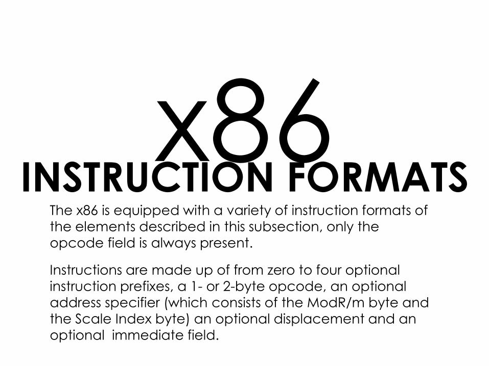
The x86 is equipped with a variety of instruction formats of
the elements described in this subsection, only the
opcode field is always present.
Instructions are made up of from zero to four optional
instruction prefixes, a 1- or 2-byte opcode, an optional address specifier (which consists of the ModR/m byte and
the Scale Index byte) an optional displacement and an
optional immediate field.
FORMATSx86 INSTRUCTION
PREFIX BYTES:
Instruction prefixes
Segment override
Operand size
Address size

FORMATSx86 INSTRUCTION
PREFIX BYTES:
Instruction prefixes
The instruction prefix, if present, consists of the LOCKprefix or one of the repeat prefixes. The LOCK prefix is used to
ensure exclusive use of shared memory in multiprocessor environments. The repeat prefixes specify repeated operation
of a string, which enables the x86 to process strings much
faster than with a regular software loop. There are five different
repeat prefixes: REP, REPE, REPZ, REPNE, and REPNZ. When the
absolute REP prefix is present, the operation specified in the
instruction is executed repeatedly on successive elements of the string; the number of repetitions is specified in register CX.
The conditional REP prefix causes the instruction to repeat until
the count in CX goes to zero or until the condition is met.
FORMATSx86 INSTRUCTION
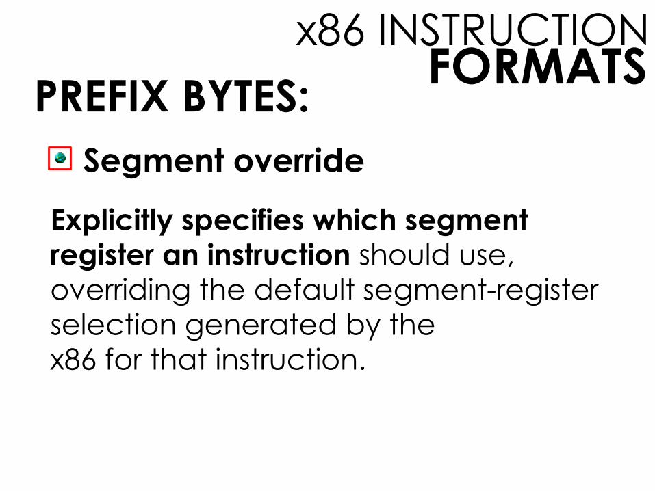
PREFIX BYTES:
Segment override
Explicitly specifies which segment register an instruction should use,
overriding the default segment-register
selection generated by the
x86 for that instruction.
FORMATSx86 INSTRUCTION
PREFIX BYTES:
Operand size
An instruction has a default operand size of 16 or 32 bits, and the operand
prefix switches between 32-bit and 16-
bit operands.
FORMATSx86 INSTRUCTION
PREFIX BYTES:
Address size
The processor can address memory using either 16- or 32-bit addresses. The address
size determines the displacement size in
instructions and the size of address offsets
generated during effective address
calculation. One of these sizes is designated
as default, and the address size prefix
switches between 32-bit and 16-bit address
generation.
FORMATSx86 INSTRUCTION
INSTRUCTION ITSELF
INCLUDES THE FOLLOWING
FIELDS:
Opcode
ModR/m
SIB
Displacement
Immediate

FORMATSx86 INSTRUCTION
INSTRUCTION ITSELF
INCLUDES THE FOLLOWING
FIELDS:
Opcode
The opcode field is 1, 2, or 3 bytes in length. The opcode may also include
bits that specify if data is byte- or full-
size (16 or 32 bits depending on
context), direction of data operation
(to or from memory), and whether an
immediate data field must be sign
extended.

FORMATSx86 INSTRUCTION
INSTRUCTION ITSELF
INCLUDES THE FOLLOWING
FIELDS:
ModR/m
This byte, and the next, provide addressing information.TheModR/m byte specifies whether an operand is in a register or in
memory; if it is in memory, then fields within the byte specifythe addressing mode to be used. The ModR/m byte consists of
three fields: The Mod field (2 bits) combines with the r/m field
to form 32 possible values: 8 registers and 24 indexing modes;
the Reg/Opcode field (3 bits) specifies either a register number
or three more bits of opcode information; the r/m field (3 bits)
can specify a register as the location of an operand, or it canform part of the addressing-mode encoding in combination
with the Mod field.

FORMATSx86 INSTRUCTION
INSTRUCTION ITSELF
INCLUDES THE FOLLOWING
FIELDS:
SIB
Certain encoding of the ModR/m byte specifies the inclusion of the SIB byte to
specify fully the addressing mode. The SIB
byte consists of three fields: The Scale field (2
bits) specifies the scale factor for scaled
indexing; the Index field (3 bits) specifies the
index register; the Base field (3 bits) specifies
the base register.
FORMATSx86 INSTRUCTION
INSTRUCTION ITSELF
INCLUDES THE FOLLOWING
FIELDS:
Displacement
When the addressing-mode specifier indicates that a displacement is used,
an 8-, 16-, or 32-bit signed integer
displacement field is added.
FORMATSx86 INSTRUCTION
INSTRUCTION ITSELF
INCLUDES THE FOLLOWING
FIELDS:
Immediate
Provides the value of an 8-, 16-, or 32-bit operand.

INSTRUCTION FORMATSARM
All instructions in the ARM architecture are 32 bits long and follow
a regular format. The first four bits of an instruction are the
condition code. Virtually all ARM instructions can be
conditionally executed. The next three bits specify the general
type of instruction. For most instructions other than branch
instructions, the next five bits constitute an opcode and/or
modifier bits for the operation. The remaining 20 bits are for
operand addressing. The regular structure of the instruction
formats eases the job of the instruction decode units.
FORMATSARM INSTRUCTION
IMMEDIATE
CONSTANTS
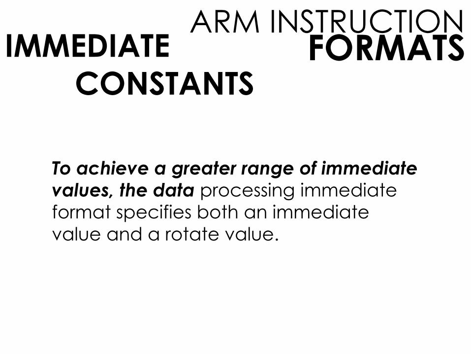
To achieve a greater range of immediate values, the data processing immediate format specifies both an immediate
value and a rotate value.
FORMATSARM INSTRUCTION
IMMEDIATE
CONSTANTS
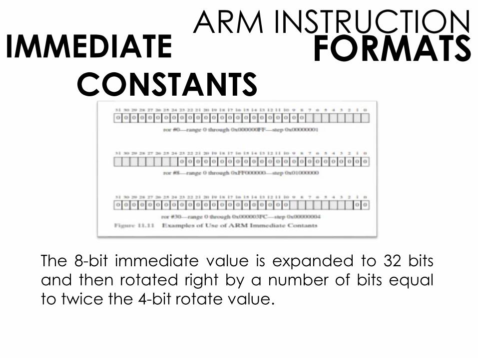
The 8-bit immediate value is expanded to 32 bits
and then rotated right by a number of bits equal
to twice the 4-bit rotate value.
FORMATSARM INSTRUCTION
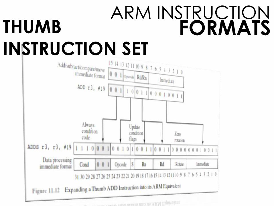
THUMB
INSTRUCTION SET
It is a re-encoded subset of the ARM instruction
set. Thumb is designed to increase the
performance of ARM implementations that use
a 16-bit or narrower memory data bus and to
allow better code density than provided by
the ARM instruction set. The Thumb instruction
set contains a subset of the ARM 32-bit
instruction set recoded into 16-bit instructions.
FORMATSARM INSTRUCTION
THUMB
INSTRUCTION SET
Thumb instructions are unconditional, so the
condition code field is not used.
Thumb has only a subset of the operations in
the full instruction set and uses only a 2-bit
opcode field, plus a 3-bit type field.
The remaining savings of 9 bits comes from
reductions in the operand specifications.
FORMATSARM INSTRUCTION
THUMB
INSTRUCTION SET

LANGUAGEASSEMBLY

LANGUAGEASSEMBLY
A processor can understand and execute
machine instructions. Such instructions are
simply binary numbers stored in the computer.
If a programmer wished to program directly in
machine language, then it would be
necessary to enter the program as binary
data.
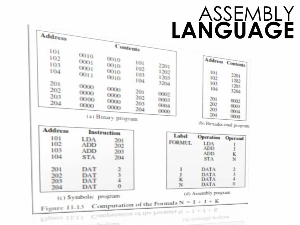
BASIC STATEMENT:
N = I + J + K

LANGUAGEASSEMBLY
FOUR INSTRUCTIONS:
1. Load the contents of location 201 into the AC.
2. Add the contents of location 202 to the AC.
3. Add the contents of location 203 to the AC.
4. Store the contents of the AC in location 204.
LANGUAGEASSEMBLY