Chapter Six: Setting Your Preferences · · 2002-06-28PC-DMIS 3.5 Reference Manual Setting Your...
92
Brown & Sharpe PC-DMIS 3.5 Reference Manual Setting Your Preferences • -6-1 Chapter Six: Setting Your Preferences Introduction PC-DMIS allows you to set personal preferences that tailor the form and function of PC-DMIS to meet individual specifications. Using this chapter you will be able to control output format, screen graphics, machine parameters and other options. The main topics in this chapter include: • Selecting PC-DMIS Setup Options • Modifying Report and Motion Parameters • Setting Up the Edit Window • Setting Up the Readout Window • Setting Up Master / Slave • Defining the Rotary Table • Setting Up Probe Changer Options • Loading the Active Probe • Setting Up the CMM Interface • Compensating for Temperature • Specifying External Directories to Search • Changing OpenGL Options The following paragraphs describe the various system options and their functions. A Note on Storing Settings for Multiple Users Any changes made to PC-DMIS's settings, parameters, or user-interface customizations are now stored for each user. This is controlled internally by using the Windows NT / Windows 2000 user permissions. Logging onto the operating system by your specific user name
Transcript of Chapter Six: Setting Your Preferences · · 2002-06-28PC-DMIS 3.5 Reference Manual Setting Your...
Brown & Sharpe
PC-DMIS 3.5 Reference Manual Setting Your Preferences •••• -6-1
Chapter Six: Setting Your Preferences
Introduction PC-DMIS allows you to set personal preferences that tailor the form and function of PC-DMIS to meet individual specifications. Using this chapter you will be able to control output format, screen graphics, machine parameters and other options.
The main topics in this chapter include:
• Selecting PC-DMIS Setup Options
• Modifying Report and Motion Parameters
• Setting Up the Edit Window
• Setting Up the Readout Window
• Setting Up Master / Slave
• Defining the Rotary Table
• Setting Up Probe Changer Options
• Loading the Active Probe
• Setting Up the CMM Interface
• Compensating for Temperature
• Specifying External Directories to Search
• Changing OpenGL Options
The following paragraphs describe the various system options and their functions.
A Note on Storing Settings for Multiple Users Any changes made to PC-DMIS's settings, parameters, or user-interface customizations are now stored for each user. This is controlled internally by using the Windows NT / Windows 2000 user permissions. Logging onto the operating system by your specific user name
Brown & Sharpe
6-2 •••• Setting Your Preferences PC-DMIS 3.5 Reference Manual
automatically recalls your settings. These are stored inside named sub directories at the location where you installed PC-DMIS.
Selecting PC-DMIS Setup Options Selecting the Setup menu option accesses the SetUp Options dialog box. This dialog box allows you to alter the form and function of PC-DMIS.
To access the tabs associated with the SetUp Options dialog box, select the Setup menu option and click on the desired tab (the "Using the Road Map" appendix provides instruction on accessing all dialog boxes and menu options). The available tabs include the following:
• General
• Part/CMM
• Dimension
• ID Setup
• Views
• NC-100 Setup
These are discussed below.
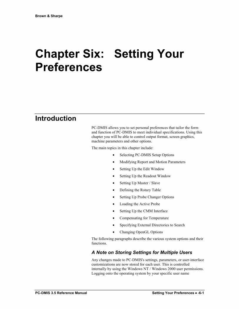
Setup Options: General tab
SetUp Options dialog box —General tab
Brown & Sharpe
PC-DMIS 3.5 Reference Manual Setting Your Preferences •••• -6-3
The General tab can be accessed by clicking on the General tab within the Setup menu option. This option will allow you to change various functions controlling the measurement process.
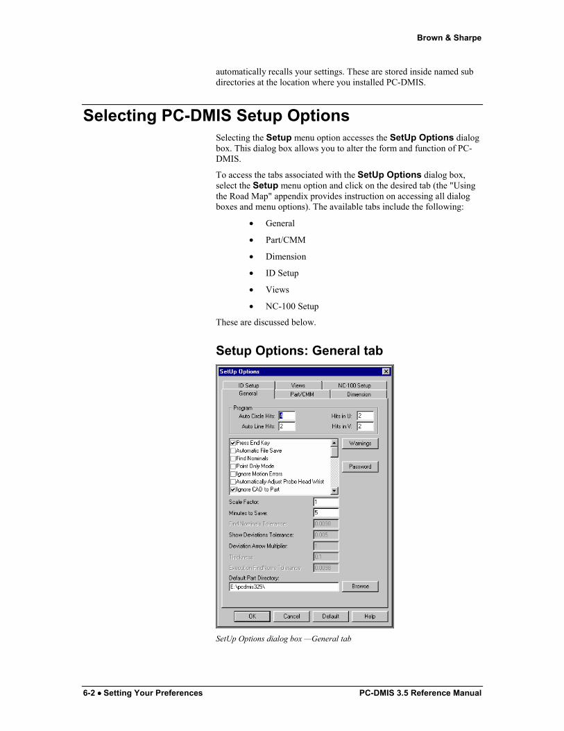
Auto Circle Hits
The Auto Circle Hits box allows you to set the default number of hits PC-DMIS will take while learning circles using CAD data. The minimum number of hits that may be entered is three. It only changes the number of hits for circles about to be programmed, not for circles that have already been programmed.
The PCDLRN.INI file for this option reads: AutoCirHits=[number of hits]
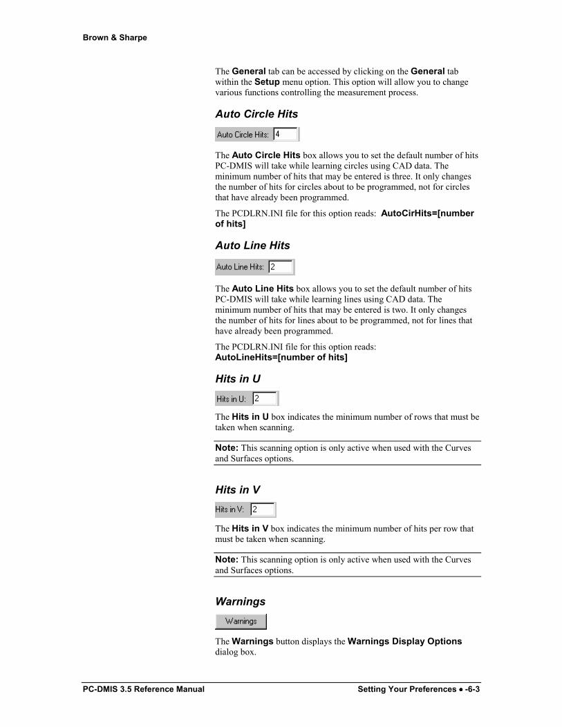
Auto Line Hits
The Auto Line Hits box allows you to set the default number of hits PC-DMIS will take while learning lines using CAD data. The minimum number of hits that may be entered is two. It only changes the number of hits for lines about to be programmed, not for lines that have already been programmed.
The PCDLRN.INI file for this option reads: AutoLineHits=[number of hits]
Hits in U
The Hits in U box indicates the minimum number of rows that must be taken when scanning.
Note: This scanning option is only active when used with the Curves and Surfaces options.
Hits in V
The Hits in V box indicates the minimum number of hits per row that must be taken when scanning.
Note: This scanning option is only active when used with the Curves and Surfaces options.
Warnings
The Warnings button displays the Warnings Display Options dialog box.
Brown & Sharpe
6-4 •••• Setting Your Preferences PC-DMIS 3.5 Reference Manual
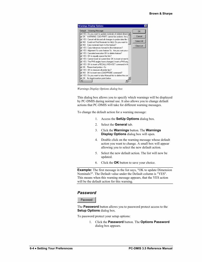
Warnings Display Options dialog box
This dialog box allows you to specify which warnings will be displayed by PC-DMIS during normal use. It also allows you to change default actions that PC-DMIS will take for different warning messages.
To change the default action for a warning message:
1. Access the SetUp Options dialog box.
2. Select the General tab.
3. Click the Warnings button. The Warnings Display Options dialog box will open.
4. Double click on the warning message whose default action you want to change. A small box will appear allowing you to select the new default action.
5. Select the new default action. The list will now be updated.
6. Click the OK button to save your choice.
Example: The first message in the list says, "OK to update Dimension Nominals?". The Default value under the Default column is "YES". This means when this warning message appears, that the YES action will be the default action for this warning.
Password
The Password button allows you to password protect access to the Setup Options dialog box.
To password protect your setup options:
1. Click the Password button. The Options Password dialog box appears.

Brown & Sharpe
PC-DMIS 3.5 Reference Manual Setting Your Preferences •••• -6-5
Options Password dialog box
2. In the New Password box, type the desired password.
3. In the Repeat entry box, re-type the same password to confirm your entry.
4. Select the Use Password check box.
5. Click OK.
The next time you attempt to access the Setup Options dialog box, you will be asked to type the password before proceeding.
If, at this request, you click Cancel you will have the option of viewing the currently selected options but will be unable to make any changes.
Check Boxes for the General tab The check boxes listed in this section of the dialog box allow you to turn on or off a variety of different options. This is useful because you can customize the way much of PC-DMIS operates in order to fit your specific needs.
Press End Key
The Press End Key check box controls whether or not the probe will automatically move to the next location after the last hit is taken on a manual feature. (It is functional only in the manual mode.) It is considered ON if the box is check marked. PC-DMIS will then require that the END key be pressed before going on to the next location.
Note: This option is useful as it allows a hit to be deleted after the last hit on the feature has been taken. If this option is turned OFF, you will not have the chance to back up hits
Automatic File Save
The Automatic File Save check box allows you to automatically save the part program at predetermined time intervals. If this check box is selected, the default setting will save the program every minute. This amount of time can be changed simply by entering another value in the Minutes to Save box.
PC-DMIS stores the autosaved file under the title of "Autosave Copy of" plus the original file name. This autosaved copy can be opened in the same manner as a regular part program in case of some catastrophic

Brown & Sharpe
6-6 •••• Setting Your Preferences PC-DMIS 3.5 Reference Manual
failure of the original file. The PCDLRN.INI file for this option reads: AutoSave=[0 or 1]
Find Nominals
The Find Nominals check box controls how PC-DMIS treats hits. When selected, PC-DMIS will then automatically consider each probe touch, finding the closest CAD nominal for that touch. It will continue to accumulate hits until the END key is pressed. The feature type will then be calculated and the CAD nominals applied.
Once selected, the Find Nominals Tolerance box becomes available. See "Find Nominals Tolerance" on page 6-15.
Point Only Mode
The Point Only Mode check box controls how PC-DMIS responds to each probe hit. When selected, PC-DMIS automatically considers each probe hit to be a single point measurement and automatically creates an Auto Vector Point. If the check box is not selected, PC-DMIS will accumulate probe hits until the END key is pressed. Only then will it determine the type of feature just measured.
When you select this check box, the Thickness for Point only Mode Points check box becomes available. See "Thickness for Point Only Mode Points" on page 6-11.
Edge Point Only Mode
The Edge Point Only Mode check box controls how PC-DMIS responds to each set of probe hits. In this case, a set is defined as two singular probe hits. The first hit should always be taken on the surface. The second hit should always be taken on the edge. When this check box is selected, PC-DMIS automatically considers each set of probe hits to be a single point measurement and automatically creates an Auto Edge Point. If the check box is not selected, PC-DMIS will accumulate probe hits until you press the END key. Only then will it determine the type of feature just measured.
PD-DMIS will use the options as displayed in the Feature Setup section of the Edge Point dialog box when creating the Edge Point (See the "Creating an Auto Edge Point" topic in the "Creating Auto Features" chapter).
CAD nominals will be applied if the Find Noms option is checked.
Brown & Sharpe
PC-DMIS 3.5 Reference Manual Setting Your Preferences •••• -6-7
Ignore Motion Error This option does not apply to all machine types. Some machines can utilize this option while on others it will have no effect.
Selecting the Ignore Motion Errors check box tells PC-DMIS to ignore collision errors. Selecting this check box and clicking OK inserts an IGNOREMOTIONERRORS/ON command into the Edit window. When PC-DMIS encounters this command and the probe collides with an obstruction, the probe will not automatically stop. This option is helpful when measuring materials such as clay or plastic, where some flexibility is necessary.
Setting this command to OFF within the Edit window will once more display collision errors.
Automatically Adjust Probe Head Wrist
If you select the Automatically Adjust Probe Head Wrist check box, PC-DMIS will select a position that most closely approximates the best approach direction automatically for each hit throughout the part program.
If PC-DMIS can find calibrated tips that fall within the angle tolerance defined in the Wrist Warning Delta box of the Part/CMM tab, it’ll use those tips over non-calibrated tips that have closer angle matches (see “Setup Options: Part/CMM tab” on page 6-17).
This option can also be turned on for individual hits of Auto Features by using the Auto PH9 check box. (See the "Creating Auto Features" chapter.)
The PCDLRN.INI file for this option reads: AutoAdjustPh9=[0 or 1]
Note: Be aware that if you use the Mark Used button on the Probe Utilities dialog box, PC-DMIS may not select all the probe tips for calibration (see the "Mark Used" topic in the "Defining Hardware" chapter).
Ignore CAD to Part
Each time you create an alignment (saved or otherwise), PC-DMIS creates two transformation matrices.
1.) Machine to part coordinates matrix.
2.) CAD to parts matrix
Machine to part coordinates: PC-DMIS compute this from the input features measured values that are stored internally in machine coordinates.
CAD to parts: PC-DMIS computes this using the same instructions as the machine to parts matrix. In this case however, the theoretical values of the input features are used instead of the measured values. Theoretical values are stored internally in CAD coordinates.
When you don't have available CAD data, theoretical data usually comes from the measured values of the learned features. It is difficult to
Brown & Sharpe
6-8 •••• Setting Your Preferences PC-DMIS 3.5 Reference Manual
get consistent results using theoretical values. This can happen when some of these values are edited, while others are not.
If you have selected the Ignore CAD to Part check box when you save an alignment, PC-DMIS only saves the machine to part alignment and does not create the CAD to parts transformation matrix. All theoretical values will now be independent of one another.
Generally, if you are not using CAD data, select this check box.
Effects on Cad Equals Part You may want to execute an alignment from features measured without CAD data in DCC mode. If you will be using the CAD Equals Part menu option (or CAD = Part button), be sure to select the Ignore CAD to Part check box prior to setting the CAD equal to the part. For information on setting the CAD equal to the part, see the "Equating CAD to Measured Part Data" topic in the "Utilities" chapter.
Theoretical Values for Copied Features If you clear this check box and copy a feature to a new location in the Edit window, the theoretical values of the feature will be associated with the alignment at the feature's original location and will seem to change.
If you select this check box and copy a feature to a new location in the Edit window, the theoretical values of the feature will be associated with the alignment at the feature's new location. And will seem to be unchanged.
Reset global settings when branching
If you select the Reset global settings when branching check box, PC-DMIS will reset the global values for state commands (see the list of commands below.) after encountering a branching statement. (For information on branching, see the "Branching by Using Flow Control" chapter for information on branching). Any state commands jumped over, because of a branching statement, will not be executed. This allows you to skip over sections of the program without having these settings change.
For example, suppose your part program has the following:
TIP/T1A0B0MYLABEL=LABEL/
Measurements etc...
TIP/T1A90B90GOTO/MYLABEL
If you select the check box, When PC-DMIS reads the GOTO statement, it jumps to MYLABEL. And then searches up, using the first encountered TIP/ command: TIP/T1A0B0
Brown & Sharpe
PC-DMIS 3.5 Reference Manual Setting Your Preferences •••• -6-9
If you deselect this check box, When PC-DMIS reads the GOTO statement, it jumps to MYLABEL. PC-DMIS won't reset global settings when encountering a branching statement. Instead, it uses the last executed TIP/ command: TIP/T1A90B90
PC-DMIS defaults to selecting the check box. In versions prior to version 3.25, PC-DMIS automatically reset the global values of the state commands. Now, PC-DMIS gives you the option to turn this option On or Off.
Commands Reset After Branching:
• Start/align
• Recall/align
• Mode/
• Rmeas/
• Workplane/
• Tip/
• Loadprobe/
• Retract/
• Check/
• Touchspeed/
• Movespeed/
• Polarvectorcomp/
• AutoTrigger/
• Triggerplane/
• TriggerTolerance/
• Videosetup/
• Displayprecision/
• ManRetract/
• Scanspeed/
• Prehit/
• Clamp/
• Clearp/
• Format/
• 132column/
• Gaponly/
• Retrolinearonly/
• Probecom/
• Array_indices/
Brown & Sharpe
6-10 •••• Setting Your Preferences PC-DMIS 3.5 Reference Manual
• Fly/
• Positivereporting/
• Ignoremotionerrors/
Move Feature to Reference Plane
If you select the Move Feature to Reference Plane check box, PC-DMIS will automatically project the measured feature to the work plane. It is only available when measuring circles, ellipses, lines and points.
Show Extended Sheet Metal Options
If you select the Show Extended Sheet Metal Options check box, PC-DMIS will display all of the available Sheet Metal options in the Auto Features dialog box. (See "Extended Sheet Metal Options" in the “Creating Auto Features" chapter.)
The PCDLRN.INI file for this option reads: ShowExtendedSheetMetal= [0 or 1]
Fixed Dialog Positions
If you select the Fixed Dialog Positions check box, PC-DMIS will display dialog boxes in their default position. If this option is not check marked, PC-DMIS will display each dialog box wherever it was last positioned. This option becomes extremely helpful when using macros.
The PCDLRN.INI file for this option reads: DialogFixedPosition=[0 or 1]
Lock Marked Sets
If you select the Lock Marked Sets check box, PC-DMIS will prevent users from accidentally deleting or otherwise modifying the current mark set configurations. PC-DMIS will only allow you to execute and activate marked sets. You must clear this check box to add or delete features from a marked set.
Automatically Scale to Fit
If you select the Automatically Scale to Fit check box, PC-DMIS will automatically scale the screen every time a feature is measured.
The PCDLRN.INI file for this option reads: AutoScaleToFit=[0 or 1]
Show Hit Deviations

Brown & Sharpe
PC-DMIS 3.5 Reference Manual Setting Your Preferences •••• -6-11
If you select the Show Hit Deviations check box, PC-DMIS will draw an arrow whenever a hit is taken to show the measured value minus the nominal deviation.
Use Circular Moves on Round Features
If you select the Use Circular Moves on Round Features check box, and if you are "learning" a part program by taking hits on the part, PC-DMIS will automatically place circular move commands into the inside circular features as well as into the outside of circular features. This includes Circles, Cylinders, Cones, and Spheres. This state, however, is only relevant during learn mode. Once the circular/move commands are present inside features they remain there unless directly removed by the user.
The PCDLRN.INI file for this option reads: UseCircularMoves=[0 or 1]
Thickness for Point Only Mode Points
When you select this check box, you can apply thickness to points created with Point Only Mode. Selecting this check box makes the Thickness box in this same dialog box available for editing. You can then type a thickness and apply that thickness to points created using Point Only Mode.
For additional information, see "Point Only Mode" on page 6-6 and "Thickness" on page 6-15.
Allow fine tuning of Alignment
If you select the Allow fine tuning of Alignment check box when an alignment is changed, PC-DMIS will ask if it should update the commands below with the changed alignment.
If you click the NO button, PC-DMIS will regenerate the program and adjust the dimensions by the offset. This allows you to manipulate your datums and re-calculate your inspection report without re-measuring all the features. Without this new option checked, the report will not be the same as before you adjusted your datums.
Use CAD Provided ID's for Features
The Use CAD Provided ID's for Features check box allows you to import feature ID's from a CAD file. When you select this check box, PC-DMIS automatically inputs the given CAD ID into the Auto Feature dialog box when the CAD feature is selected with a left mouse click. If you decide to keep this value, then the feature created will have the given ID.
Brown & Sharpe
6-12 •••• Setting Your Preferences PC-DMIS 3.5 Reference Manual
Find Nominals During Execution
If you select the Find Nominals during Execution check box, new nominals are found for both Surface and Vector points during part program execution. See "Execution FindNoms Tolerance" on page 6-15 on page 6-15 to define the tolerance values PC-DMIS will use. Also, see "Find Nominals Tolerance" on page 6-15.
Auto Continue Execution if FindHole Fails
If you select the Auto Continue Execution if FindHole Fails check box, PC-DMIS allows you to automatically continue executing a part if the "FindHole" option found on the Auto Feature dialog box fails to find a hole.
In the past, when the “FindHole” option failed, PC-DMIS prompted you to place the probe in the center of the hole to continue running the part program. However, with the Auto Continue Execution if FindHole Fails check box selected, PC-DMIS automatically prints an error message to the report and continues running the remaining part program.
For more specific information on Find Hole, see the "Find Hole Check Box" topic in the "Creating Auto Features" chapter:
Show Startup Dialog
The Show Startup Dialog check box allows you to determine whether or not PC-DMIS shows the Open File dialog box each time you start PC-DMIS. This dialog box shows a listing of available part programs to open.
When you clear the check box, PC-DMIS will disable this startup dialog.
See "Opening Existing Part Programs" in the "Using Basic File Options" chapter for additional information on the Open File dialog box.
Automatic Label Positioning
The Automatic label positioning check box tells PC-DMIS to automatically position feature labels around the part.
Animate Probe during Program Mode
The Animate probe during Program Mode check box activates probe animation during Program mode. When you select this check box, the probe will animate the taking of hits in the Graphics Display window as the hits are generated from CAD.

Brown & Sharpe
PC-DMIS 3.5 Reference Manual Setting Your Preferences •••• -6-13
Show Icon in Text Boxes
The Show icon in text boxes check box allows you to determine if icons depicting the feature or dimension type should appear in text boxes and inside feature ID labels. The text boxes include feature ID, dimension info, and point info text boxes.
For information on text boxes see "Text Box Mode" in the "Editing the CAD Display" chapter.
Pierce CAD on 3D Rotate
The Pierce CAD on 3D rotate check box allows you to determine the exact point about which PC-DMIS rotates when performing a 3D rotate by simply right-clicking in the Graphics Display window.
• If you select this check box and perform a 3D rotate by right-clicking in the Graphics Display window, PC-DMIS uses the point where you clicked as the point used about which to rotate.
• If you clear this check box and then right-click to 3D rotate, then PC-DMIS doesn't pierce the CAD.
Note: As always, however, if PC-DMIS detects a wire frame entity or surface edge close to the mouse cursor, then the point on the entity or edge closest to the mouse pointer will be used as the rotation point.
See "3D Rotate Mode" discussed in the "Editing the CAD Display" chapter for information on 3D rotating.
Save Part Program on Execute
The Save Part Program on Execute check box tells PC-DMIS to automatically save the current part program whenever it's executed.
Use DMIS Button in Edit Window
The Use DMIS Button in Edit Window check box determines whether or not the DMIS mode icon gets displayed on the Edit window toolbar.
Patch Scans Maintain Last Increment
The Patch Scans Maintain Last Increment check box forces each new line of the patch scan to use the last increment from the previous line. If you deselect this check box, the scan will revert to the minimum scan increment when taking the first hit on each line.
Brown & Sharpe
6-14 •••• Setting Your Preferences PC-DMIS 3.5 Reference Manual
Use Automotive Deviation Letters
The Use Automotive Deviation Letters check box causes PC-DMIS to add a letter after the deviation number in Location and True Position dimension reports. PC-DMIS inserts the letter
• F when the feature deviates in the direction of the front of the car.
• B when the feature deviates in the direction of the back of the car.
• I when the feature deviates towards the centerline of the car (meaning the car is too narrow).
• O when the feature deviates away from the centerline of the car (meaning the car is too wide).
• H when the feature deviates towards the top of the car.
• L when the feature deviates towards the bottom of the car.
These letters are added to the Location and True Position dimensions just following the deviation numbers reported.
Edit Boxes for the General tab The edit boxes for the General tab allow you to edit the following options:
• Scale Factor
• Minutes to Save
• Find Nominals Tolerance
• Show Deviations Tolerance
• Deviation Arrow Multiplier
• Thickness
• Execution FindNoms Tolerance
• Default Part Directory
Scale Factor
The Scale Factor box scales the measured data by what ever factor is entered. For example, if a circle is measured and has a diameter of 1.0 inches and the scale factor is 0.95 then the measured value will be reported as 0.95 inches.
Minutes to Save
The Minutes to Save box allows you to enter the amount of minutes that PC-DMIS will wait before auto saving your part program. The

Brown & Sharpe
PC-DMIS 3.5 Reference Manual Setting Your Preferences •••• -6-15
least amount of minutes you can enter is one. The Minutes to Save box becomes available when you select the Automatic File Save check box.
Find Nominals Tolerance
This box becomes available when you first select the Find Nominals check box. See "Find Nominals" on page 6-6.
The Find Nominals Tolerance box allows you to type the amount of tolerance that PC-DMIS uses when finding the nominals. You must type in an amount greater than the radius of the probe ball or else the Find Nominals operation will fail.
Show Deviations Tolerance
The Show Deviations Tolerance box allows you to type the amount of tolerance that PC-DMIS uses when PC-DMIS is showing hit deviations. This option is only available when you first select the Show Hit Deviation check box.
Deviation Arrow Multiplier
The Deviation Arrow Multiplier box is only available when you first select the Show Hit Deviation check box. An arrow appears in the Graphics Display window marking each hit taken, showing the deviation. The larger the value entered in this field, the greater the size of the arrow.
Thickness
The Thickness box works with the Thickness for Point Only Mode Points check box. If you select the Thickness for Point Only Mode Points check box, the thickness in this box will be applied to each point created by Point Only Mode.
See "Point Only Mode" on page 6-6 and "Thickness for Point Only Mode Points" on page 6-11 for additional information.
Execution FindNoms Tolerance
The Execution FindNoms Tolerance box allows you to type the amount of tolerance that PC-DMIS uses when finding the nominals during part program execution. This box becomes available when you first select the Find Nominals during Execution check box.
See "Find Nominals During Execution" on page 6-12.
Brown & Sharpe
6-16 •••• Setting Your Preferences PC-DMIS 3.5 Reference Manual
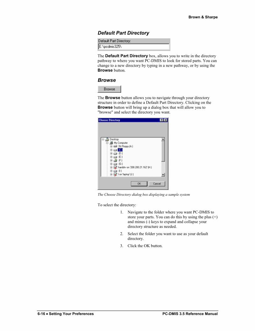
Default Part Directory
The Default Part Directory box, allows you to write in the directory pathway to where you want PC-DMIS to look for stored parts. You can change to a new directory by typing in a new pathway, or by using the Browse button.
Browse
The Browse button allows you to navigate through your directory structure in order to define a Default Part Directory. Clicking on the Browse button will bring up a dialog box that will allow you to "browse" and select the directory you want.
The Choose Directory dialog box displaying a sample system
To select the directory:
1. Navigate to the folder where you want PC-DMIS to store your parts. You can do this by using the plus (+) and minus (-) keys to expand and collapse your directory structure as needed.
2. Select the folder you want to use as your default directory.
3. Click the OK button.

Brown & Sharpe
PC-DMIS 3.5 Reference Manual Setting Your Preferences •••• -6-17
Setup Options: Part/CMM tab
Setup Options dialog box—Part/CMM tab
The Part/CMM tab lets you define the part setup on the CMM by changing the CAD axes relationship to the machine axes. This option can be accessed by clicking on the Part/CMM tab within the SetUp Option dialog box.
This capability is needed when a program is being created using PC-DMIS, and the CAD coordinate system differs from the CMM part setup.
Example: A part is set up on the machine with its X+ CAD axis pointing in the same direction as the CMM's Z+ axis. The Z+ CAD axis is pointing in the same direction as the CMM's X- axis. This function can be used to create the proper relationships.
To equate the CAD setup to the part’s, simply select the appropriate axes from the drop-down lists. Once this relationship is established, it will be easier to program the part because PC-DMIS will properly display the probe in relation to the part.
Probe Head Orientation
The Probe Head Orientation button allows you to configure the probe head wrist AB angles for both Master and Slave arms.
Brown & Sharpe
6-18 •••• Setting Your Preferences PC-DMIS 3.5 Reference Manual
To configure the AB wrist angles for both Master and Slave arms:
1. Access the SetUp Options dialog box.
2. Select the Part/CMM tab.
3. Click the Probe Head Orientation button. The Probe Head Wrist Angle Configuration dialog box will appear.
4. Select the appropriate axes for the AB angles for both Master and Slave arms (if applicable).
5. Click the OK button.
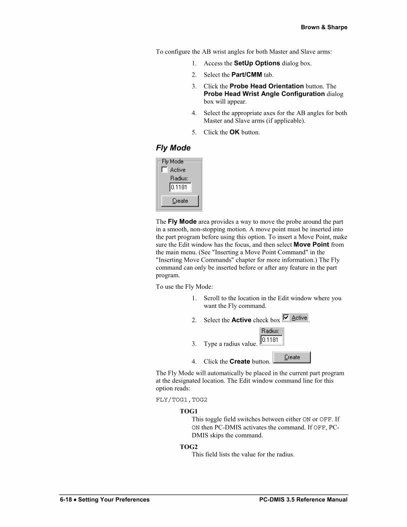
Fly Mode
The Fly Mode area provides a way to move the probe around the part in a smooth, non-stopping motion. A move point must be inserted into the part program before using this option. To insert a Move Point, make sure the Edit window has the focus, and then select Move Point from the main menu. (See "Inserting a Move Point Command" in the "Inserting Move Commands" chapter for more information.) The Fly command can only be inserted before or after any feature in the part program.
To use the Fly Mode:
1. Scroll to the location in the Edit window where you want the Fly command.
2. Select the Active check box .
3. Type a radius value.
4. Click the Create button.
The Fly Mode will automatically be placed in the current part program at the designated location. The Edit window command line for this option reads:
FLY/TOG1,TOG2
TOG1 This toggle field switches between either ON or OFF. If ON then PC-DMIS activates the command. If OFF, PC-DMIS skips the command.
TOG2 This field lists the value for the radius.

Brown & Sharpe
PC-DMIS 3.5 Reference Manual Setting Your Preferences •••• -6-19
If you have selected an illegal position, a message appears informing you that PC-DMIS cannot insert at the current line. The message then asks if it should insert the command at the next legal position.
• If you click the Yes button, PC-DMIS will move the Fly command down to the end of the current feature in the Edit window.
• If you click the No button, PC-DMIS will cancel the Fly command and return you to the Part/CMM tab.
When the part program is executed, PC-DMIS will move the probe a predetermined distance from the move point without any hesitation. The distance moved is the value entered in the Radius box.
Wrist Warning Delta
This is a numerical value defining the minimum change in the wrist angle required before PC-DMIS requires you to change the current wrist position. This only affects users with a DCC CMM with a PH9 articulated wrist.
Manual Hit Retract
This option is only available with certain DCC CMM types (such as LK and Mitutoyo).
The Manual Hit Retract box allows you to type the retract distance the CMM will automatically travel after a manual hit is taken. If the Manual Hit Retract value is changed from either the default or from the last used value, then PC-DMIS places a retract command (shown as "MANRETRACT/" and then the value) in the current part program's Edit window at the cursor's location. As manual hits are taken, the CMM will retract by the new value stated on this command.
For example, if you change the Manual Hit Retract value from the .1 default to .003 then the command "MANRETRACT/0.003" appears in the Edit window.
Display Absolute Speed
If the Display Absolute Speed check box is selected, PC-DMIS will display the Move Speed as an absolute value instead of a percentage. This value corresponds to the set unit type of the part program (inches or millimeters).
Top Speed (mm/sec)
The Top Speed (mm/sec) box allows you to reset the top speed that the machine can travel. The value that is specified cannot exceed the machine's designated top speed. The value that is set works in conjunction with the Move Speed option.

Brown & Sharpe
6-20 •••• Setting Your Preferences PC-DMIS 3.5 Reference Manual
CAD X+ Axis=
The CAD X+ Axis= drop-down list allows you to set the relationship between the CAD X+ axis and the machine axis.
This capability is needed when a program is being created using PC-DMIS, and the CAD coordinate system differs from the CMM part setup.
CAD Y+ Axis=
The CAD Y+ Axis= drop-down list allows you to set the relationship between the CAD Y+ axis and the machine axis.
This capability is needed when a program is being created using PC-DMIS, and the CAD coordinate system differs from the CMM part setup.
CAD Z+ Axis=
'This drop down list allows you to set the relationship between the CAD Z+ axis and the machine axis.
This capability is needed when a program is being created using PC-DMIS, and the CAD coordinate system differs from the CMM part setup.
X Offset
The X Offset box allows you enter the distance that PC-DMIS will offset the CAD drawing along the X axis. PC-DMIS will shift the CAD drawing along the X axis the specified distance. For example, if you enter in .5 in this field, the entire CAD display in the Graphics Display window will shift the distance of .5 in the X direction.
Note: All features created in the part program will not shift along the axis with the CAD drawing.
Y Offset
The Y Offset box allows you enter the distance that PC-DMIS will offset the CAD drawing along the Y axis. PC-DMIS will shift the CAD drawing along the Y axis the specified distance. For example, if you enter in .5 in this field, the entire CAD display in the Graphics Display window will shift the distance of .5 in the Y direction.
Brown & Sharpe
PC-DMIS 3.5 Reference Manual Setting Your Preferences •••• -6-21
Note: All features created in the part program will not shift along the axis with the CAD drawing.
Z Offset
The Z Offset box allows you enter the distance that PC-DMIS will offset the CAD drawing along the Z axis. PC-DMIS will shift the CAD drawing along the Z axis the specified distance. For example, if you enter in .5 in this field, the entire CAD display in the Graphics Display window will shift the distance of .5 in the Z direction.
Note: All features created in the part program will not shift along the axis with the CAD drawing.
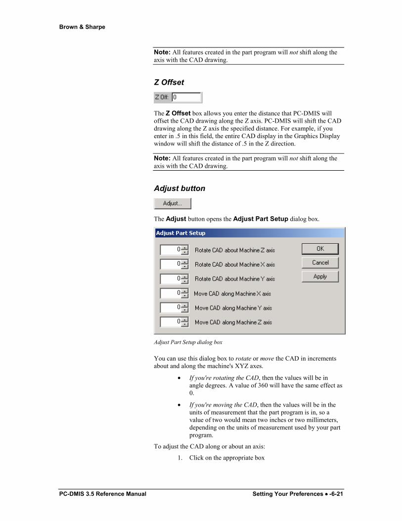
Adjust button
The Adjust button opens the Adjust Part Setup dialog box.
Adjust Part Setup dialog box
You can use this dialog box to rotate or move the CAD in increments about and along the machine's XYZ axes.
• If you're rotating the CAD, then the values will be in angle degrees. A value of 360 will have the same effect as 0.
• If you're moving the CAD, then the values will be in the units of measurement that the part program is in, so a value of two would mean two inches or two millimeters, depending on the units of measurement used by your part program.
To adjust the CAD along or about an axis:
1. Click on the appropriate box
Brown & Sharpe
6-22 •••• Setting Your Preferences PC-DMIS 3.5 Reference Manual
2. Type a new value. PC-DMIS dynamically shows the adjustment in the Graphics Display window.
3. Click OK to accept the values and close the dialog box.
PC-DMIS will maintain this adjustment unless you re-import the part's CAD model.
Apply button
The Apply button immediately applies any changes made in the X, Y, or Z Offset fields and shifts the drawing along the appropriate axis (axes) while keeping the dialog box open.
Auto Position button
The Auto Position button automatically positions the part onto the graphical representation of the machine. Auto position best guesses where to position the part on the graphical representation. You can either let PC-DMIS determine where to put the part in relation to the CMM by using this function, or you can key in your own positioning using the XYZ offset fields. (See "Defining Machines" in the Defining Hardware chapter for more information on setting up the graphical representation of the CMM.)
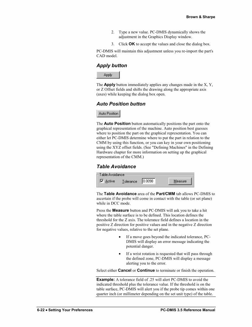
Table Avoidance
The Table Avoidance area of the Part/CMM tab allows PC-DMIS to ascertain if the probe will come in contact with the table (or set plane) while in DCC mode.
Press the Measure button and PC-DMIS will ask you to take a hit where the table surface is to be defined. This location defines the threshold for the Z axis. The tolerance field defines a location in the positive Z direction for positive values and in the negative Z direction for negative values, relative to the set plane.
• If a move goes beyond the indicated tolerance, PC-DMIS will display an error message indicating the potential danger.
• If a wrist rotation is requested that will pass through the defined zone, PC-DMIS will display a message alerting you to the error.
Select either Cancel or Continue to terminate or finish the operation.
Example: A tolerance field of .25 will alert PC-DMIS to avoid the indicated threshold plus the tolerance value. If the threshold is on the table surface, PC-DMIS will alert you if the probe tip comes within one quarter inch (or millimeter depending on the set unit type) of the table.

Brown & Sharpe
PC-DMIS 3.5 Reference Manual Setting Your Preferences •••• -6-23
Note: The Table Avoidance option is available with certain interface types only while in DCC mode.
Default button
The Default button allows you to update the default settings to several of the Part/CMM Setup parameters. When a new part program is created, it will reflect any changes made to the accessible parameters, only if the Default button is pressed. If the OK button is selected (without the Default button being pressed) the defined parameters will only apply to the active part program and will not affect PC-DMIS's registry entries. The default values are stored in the registry. These parameters can be updated in the appropriate dialog box or by using the PC-DMIS Settings Editor. See the "Modifying Registry Entries" chapter.
If any of the parameters are changed and the Default button is clicked, PC-DMIS will update the registry file, redefining the default to the current setting.
Setup Options: Dimension tab
Setup Options dialog box—Dimension tab
The Dimension tab lets you access the dimensional printout parameters.
Brown & Sharpe
6-24 •••• Setting Your Preferences PC-DMIS 3.5 Reference Manual
To access the Dimension tab
1. Access the SetUp Options dialog box.
2. Click the Dimension tab.
Auto Roundness
The Auto Roundness check box tells PC-DMIS to automatically create a new roundness dimension whenever a new circle, cylinder, cone, or sphere is created. The new dimension will be displayed in the Edit window immediately following the feature. The dimension will be automatically deleted when the next feature is measured unless you select the Auto Save Dimensions check box, or edit the dimension in the Edit window.
Auto Create Dimensions
The Auto Create Dimensions check box tells PC-DMIS to automatically create a new dimension whenever a new feature is created. This new dimension will be displayed in the Edit window following the feature. The dimension will be either a location or true position dimension, depending on which dimension type was last created through the usual method of selecting features in a dimension dialog box.
Auto Textual Analysis
The Auto Textual Analysis check box controls whether or not PC-DMIS will automatically create textual analysis of the dimension. It is considered ON if the box is marked.
Auto Graphical Analysis
The Auto Graphical Analysis check box controls whether or not PC-DMIS will automatically create a graphical analysis of any dimension that is created with Auto Create Dimensions or Auto Roundness. See "Analysis Settings" in the "Dimensioning Features" chapter and "Analysis" in the "Inserting Reporting Commands" chapter.
Auto Dimension Info
The Auto Dimension Info check box controls whether or not PC-DMIS will automatically create a Dimension Information check box for any dimension created with the Auto Create Dimensions check box or the Auto Roundness check box. See "Inserting Dimension Info Boxes" in the "Inserting Report Commands" chapter for
Brown & Sharpe
PC-DMIS 3.5 Reference Manual Setting Your Preferences •••• -6-25
information on how to set the default formats for this Dimension Info boxes.
Multiply
The Multiply value is a scaling factor that magnifies the arrow and tolerance zone for the graphical analysis mode. If a value of 2.0 is entered, PC-DMIS will scale the arrow two times the graphical image.
The Multiply box is used for viewing purposes only, and is not reflected in the text printout.
Always Save Stats to File
The Always Save Stats to File check box allows you to bypass the prompt asking you to save stats data that appears whenever execution of a part program starts with a valid STATS/ON command. The statistical data will automatically be saved to the XSTATS11.tmp file if this option is check marked and a STATS/ON command exists in the part program when it is executed. See the "Tracking Statistical Data" chapter for more information.
Always Update Database
The Always Update Database check box allows PC-DMIS to update your statistical database software with the information in the XSTATS11.tmp file without the prompt asking to update the database now every time the part program is executed and statistical data is collected and saved. If this option is not check marked, PC-DMIS will continue displaying this prompt before updating the database software. See the "Tracking Statistical Data" chapter for more information.
Features Use Dimension Colors
The Features Use Dimension Colors check box tells PC-DMIS to color features that have an associated dimension. Features are drawn in the Graphics Display window with the same colors that the dimension uses to indicate deviation from the theoretical values.
Minus Tols Show Negative
The Minus Tols Show Negative check box controls whether or not the minus tolerances of the dimensions will be displayed with a minus sign. For example, if the dimension is specified as 5.0000 +0.3 (upper tolerance), -0.2 (lower tolerance), the dimension line may be displayed as follows if this check box is selected:

Brown & Sharpe
6-26 •••• Setting Your Preferences PC-DMIS 3.5 Reference Manual
AX NOM +TOL -TOL MEAS MAX MIN DEV OUT-TOL
Y 5.0000 0.3000 -0.2000 5.0000 0.0000 0.0000 0.0000 0.0000
If this check box is cleared, the same example may be displayed as follows:
AX NOM +TOL -TOL MEAS MAX MIN DEV OUT-
TOL Y 5.0000 0.3000 0.2000 5.0000 0.0000 0.0000 0.0000 0.0000
This check box does not affect how the values are stored or used in calculations. It only controls how the values are displayed according to user preference. This check box is not selected by default.
Number of Decimal Places
The Number of Decimal Places area controls the number of decimal places printed on the inspection report by PC-DMIS while in inch mode. The available options are one through five. Choose the desired option to determine the number of decimal places that will be printed.
If the unit type is mm, PC-DMIS will display the available options of zero through four.
Each time this is changed in a program PC-DMIS places a command: DISPLAYPRECISION/ # into the part program. This specifies the precision to be displayed at this section of the program. If this command is not used then the default value is automatically used. If this command is used the precision will stay as specified unless changed by another instance of the command.
Positive Reporting
The check boxes related to the Positive Reporting area control the reporting of features to the negative side of the origin that would normally have negative values to always be printed with positive values.
• The X, Y, and Z check boxes determine on which axis (or axes) PC-DMIS will display positive numbers.
• The All Data option tells PC-DMIS to display the measured and nominal values of the selected axis (or axes) as positive numbers.
Brown & Sharpe
PC-DMIS 3.5 Reference Manual Setting Your Preferences •••• -6-27
• The Deviations Only option tells PC-DMIS to display only the deviations of the selected axis (or axes) as positive numbers.
When these check boxes are selected, a POSITIVEREPORTING command is inserted into the part program at the current cursor position. This command has the following format in the Edit window:
POSITIVEREPORTING/ a, b, c, TOG1
Where:
a = X when the X check box is selected, or blank if the X check box is cleared.
b = Y when the Y check box is selected, or blank if the Y check box is cleared.
c = Z when the Z check box is selected, or blank if the Z check box is cleared.
TOG1 = ALLDATA or DEVONLY depending on whether you selected the All Data or Deviations Only option.
The X, Y, and Z direction may each have positive reporting turned on in any combination of the three. Multiple POSITIVEREPORTING commands may be used within the same part program, and any dimensions that are in the part program are displayed using the POSITIVEREPORTING command that precedes the dimensions. If no POSITIVEREPORTING command exists in the part program, all dimensions are reported with the options turned OFF in the X, Y, and Z directions.
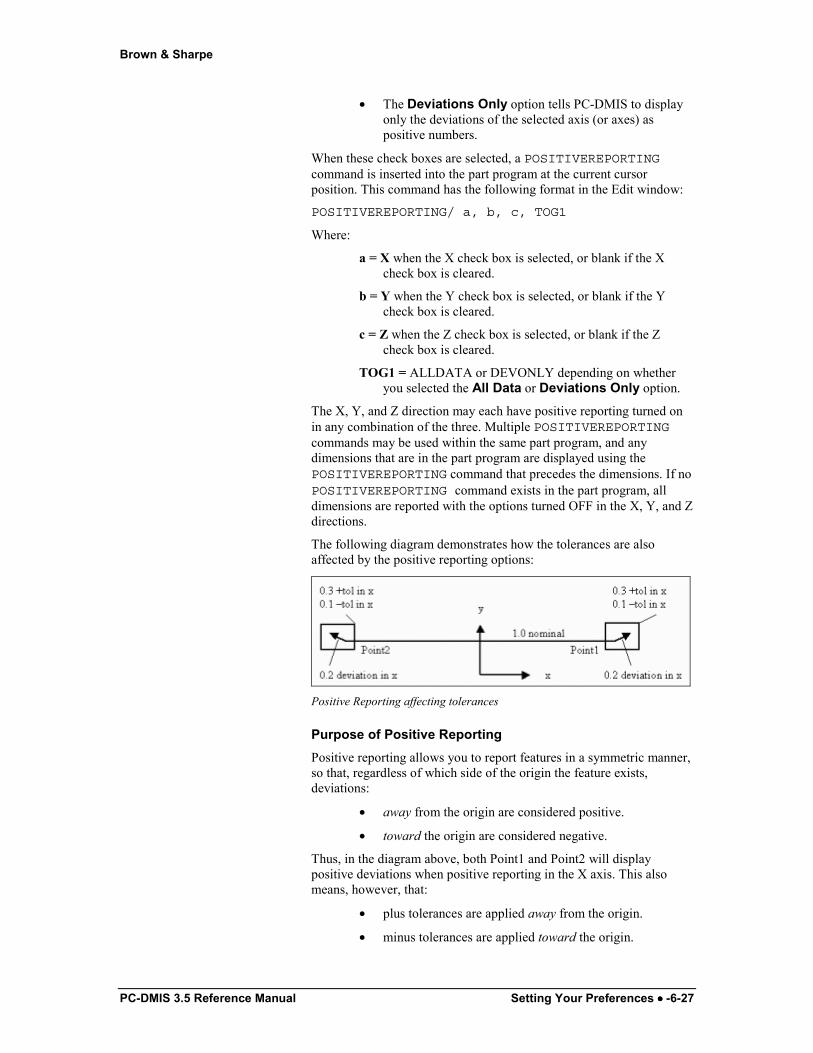
The following diagram demonstrates how the tolerances are also affected by the positive reporting options:
Positive Reporting affecting tolerances
Purpose of Positive Reporting Positive reporting allows you to report features in a symmetric manner, so that, regardless of which side of the origin the feature exists, deviations:
• away from the origin are considered positive.
• toward the origin are considered negative.
Thus, in the diagram above, both Point1 and Point2 will display positive deviations when positive reporting in the X axis. This also means, however, that:
• plus tolerances are applied away from the origin.
• minus tolerances are applied toward the origin.
Brown & Sharpe
6-28 •••• Setting Your Preferences PC-DMIS 3.5 Reference Manual
Default Tolerances: Set Defaults
The Set Defaults check box sets the default tolerances during the Learn mode based upon the precision of the nominal values. When necessary, these values can be overridden by entering the tolerances individually in the print preview box. This option only affects the tolerances when a nominal of a dimension is edited.
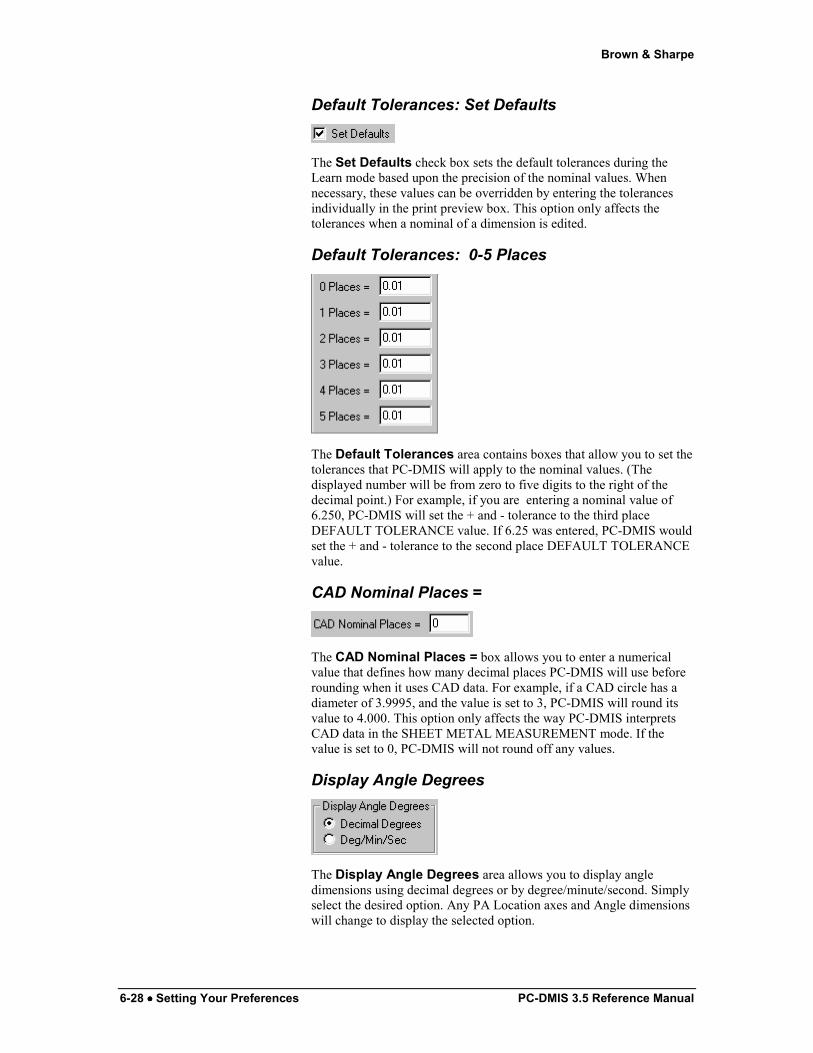
Default Tolerances: 0-5 Places
The Default Tolerances area contains boxes that allow you to set the tolerances that PC-DMIS will apply to the nominal values. (The displayed number will be from zero to five digits to the right of the decimal point.) For example, if you are entering a nominal value of 6.250, PC-DMIS will set the + and - tolerance to the third place DEFAULT TOLERANCE value. If 6.25 was entered, PC-DMIS would set the + and - tolerance to the second place DEFAULT TOLERANCE value.
CAD Nominal Places =
The CAD Nominal Places = box allows you to enter a numerical value that defines how many decimal places PC-DMIS will use before rounding when it uses CAD data. For example, if a CAD circle has a diameter of 3.9995, and the value is set to 3, PC-DMIS will round its value to 4.000. This option only affects the way PC-DMIS interprets CAD data in the SHEET METAL MEASUREMENT mode. If the value is set to 0, PC-DMIS will not round off any values.
Display Angle Degrees
The Display Angle Degrees area allows you to display angle dimensions using decimal degrees or by degree/minute/second. Simply select the desired option. Any PA Location axes and Angle dimensions will change to display the selected option.

Brown & Sharpe
PC-DMIS 3.5 Reference Manual Setting Your Preferences •••• -6-29
Angle Degrees
The Angle Degrees area will also allow you to display the angle dimension from 0° -360° or 0° to +/- 180°. Any PA Location axes and Angle dimensions will change to lie within the selected angle degree range.
Default button for Dimension tab
The Default button allows you to apply changes made in the SetUp Options dialog box to all new part programs created later on.
The Default button allows you to update the default settings to several of the Dimension Setup parameters. When a new part program is created, it will reflect any changes made to the accessible parameters, only if the Default button is clicked.
For additional information on Default buttons, see the "Default" topic in the "Navigating the User Interface" chapter.
Setup Options: ID Setup tab
Setup Options dialog box—ID Setup tab
Brown & Sharpe
6-30 •••• Setting Your Preferences PC-DMIS 3.5 Reference Manual
It is important to keep track of ID's already set when changing an identification. It is possible to have ID duplication through multiple changes to this option.
The ID Setup tab allows you to alter the format used to identify alignments, dimensions, features, comments, labels and variables.
To access this option:
1. Access the Setup Options dialog box.
2. Select the ID setup tab.
The default ID Setup option is Generic. As each feature is created, PC-DMIS will assign it an ID beginning with the letter F, followed by a number (incrementally set from the starting number of one). You may choose to override this setting by selecting the following options:
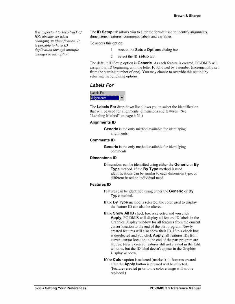
Labels For
The Labels For drop-down list allows you to select the identification that will be used for alignments, dimensions and features. (See "Labeling Method" on page 6-31.)
Alignments ID Generic is the only method available for identifying
alignments.
Comments ID Generic is the only method available for identifying
comments.
Dimensions ID Dimensions can be identified using either the Generic or By
Type method. If the By Type method is used, identifications can be similar to each dimension type, or different based on individual need.
Features ID Features can be identified using either the Generic or By
Type method.
If the By Type method is selected, the color used to display the feature ID can also be altered.
If the Show All ID check box is selected and you click Apply, PC-DMIS will display all feature ID labels in the Graphics Display window for all features from the current cursor location to the end of the part program. Newly created features will also show their ID. If this check box is deselected and you click Apply, all features IDs from current cursor location to the end of the part program are hidden. Newly created features still get created in the Edit window, but the ID label doesn't appear in the Graphics Display window.
If the Color option is selected (marked) all features created after the Apply button is pressed will be effected. (Features created prior to the color change will not be replaced.)

Brown & Sharpe
PC-DMIS 3.5 Reference Manual Setting Your Preferences •••• -6-31
Labels ID Generic is the only method available for identifying labels.
Variables ID Generic is the only method available for identifying
variables.
Call Subs ID Generic is the only method available for identifying Called
Subroutines.
Labeling Method
This drop down window allows you to select between By Type and Generic identification methods.
By Type By Type lets you set the identification for each element type
(circle, cone, cylinder, line, plane, point and sphere).
Generic Generic will apply the same identification system regardless
of feature (dimension) type.
PC-DMIS has no inherent limit on the number of letters used for identifications. However, the Graphic Display area and Edit window have limits on the ID length. Even if the Edit window does not show the complete ID, PC-DMIS will internally keep track of the complete identification.
Starting Letters
The Starting Letters box determines the first letter(s) that will be used in the identification process. PC-DMIS will always display the ID using capital letters. Up to 15 characters can be typed in.
Note: In various dialog boxes where the ID is displayed, changing the text portion of the ID the default text of the ID may also be set.
Starting Number
The Starting Number box determines the first number that will be used in the identification process. Any number between 1 and 9999 can be entered.
Brown & Sharpe
6-32 •••• Setting Your Preferences PC-DMIS 3.5 Reference Manual
Note: In various dialog boxes where the ID is displayed, changing only the number portion of an ID the counter may be reset to a desired count
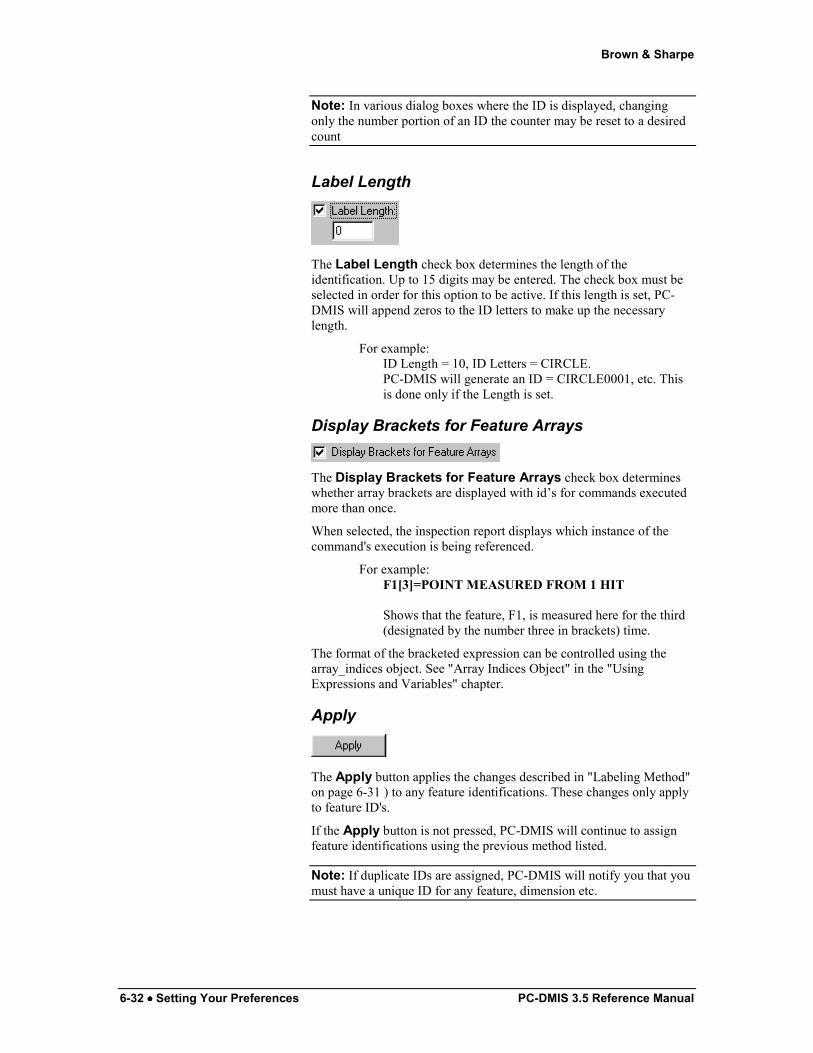
Label Length
The Label Length check box determines the length of the identification. Up to 15 digits may be entered. The check box must be selected in order for this option to be active. If this length is set, PC-DMIS will append zeros to the ID letters to make up the necessary length.
For example: ID Length = 10, ID Letters = CIRCLE. PC-DMIS will generate an ID = CIRCLE0001, etc. This is done only if the Length is set.
Display Brackets for Feature Arrays
The Display Brackets for Feature Arrays check box determines whether array brackets are displayed with id’s for commands executed more than once.
When selected, the inspection report displays which instance of the command's execution is being referenced.
For example: F1[3]=POINT MEASURED FROM 1 HIT Shows that the feature, F1, is measured here for the third (designated by the number three in brackets) time.
The format of the bracketed expression can be controlled using the array_indices object. See "Array Indices Object" in the "Using Expressions and Variables" chapter.
Apply
The Apply button applies the changes described in "Labeling Method" on page 6-31 ) to any feature identifications. These changes only apply to feature ID's.
If the Apply button is not pressed, PC-DMIS will continue to assign feature identifications using the previous method listed.
Note: If duplicate IDs are assigned, PC-DMIS will notify you that you must have a unique ID for any feature, dimension etc.

Brown & Sharpe
PC-DMIS 3.5 Reference Manual Setting Your Preferences •••• -6-33
Default Settings
The Default button allows you to update the default settings to all of the ID Setup parameters. When a new part program is created, it will reflect any changes made to the parameters, only if the Default button is clicked.
For additional information on Default buttons, see the "Default" topic in the "Navigating the User Interface" chapter.
Note: Always press the Apply button after a change is made (before pressing the OK or Default buttons).
Setup Options: Views tab
SetUp Options dialog box—Views tab
With the Views tab, you are able to tell PC-DMIS to store and recall the position and size of both the Edit window and the Graphics Display window for each individual part program. For new part programs, PC-DMIS also stores the default location and size for each window type in the .INI file.
Various boxes and buttons are supplied which allow you to enter or change information. These are explained here:
X Loc: This box displays the location of the desired window X direction along the X direction of the computer screen.
Brown & Sharpe
6-34 •••• Setting Your Preferences PC-DMIS 3.5 Reference Manual
Y Loc: This box displays the location of the desired window along the Y direction of the computer screen.
Width: This box shows the desired window's current width.
Height: This box shows the desired window's current height.
Normal: This option tells PC-DMIS to store the window in its normal state, neither maximized, or minimized.
Maximized: This option tells PC-DMIS to store the window in its maximized (or full screen) state.
Minimized: This option tells PC-DMIS to store the window in its minimized (or where only the title bar is showing) state.
Get Current: Clicking this button will place the X and Y location values and the height and width of the window into their corresponding fields. The Normal, Maximized, and Minimized options also show the current state of the window.
Set Defaults: This button writes size and location changes of the Edit window or Graphics Display window to the .INI file. Any new part programs created will start with these new size and location defaults.
PC-DMIS allows you to store the windows' sizes and locations by either keying in the values or through dragging the windows to the desired location.
Keying in the Location and Size To store a window size and location for your part programs by keying in the values:
1. Access the SetUp Options dialog box.
2. Click the Views tab.
3. Type in the X, and Y values of the window's position in the X Loc. box and in the Y Loc. box.
4. Type the width and height in Width box and Height box.
5. Choose the Normal, Maximized or Minimized option in the dialog box.
6. Click the OK button.
Dragging the Window for the Location and Size To store a window size and location for your part programs by
dragging the window:
1. Access the SetUp Options dialog box.
2. Click the Views tab.
3. Click on either the Edit window or the Graphics Display window.
4. Change the location and size of the window to fit your needs.
5. Click the OK button.
Brown & Sharpe
PC-DMIS 3.5 Reference Manual Setting Your Preferences •••• -6-35
Note: New defaults will only be applied to newly created part programs. PC-DMIS stores the Size, Location, and State of both windows when the PC-DMIS is closed. When these programs are re-opened they will be restored to the size and location they were in when the program was closed. The only exception is if one part program is currently opened and maximized and a second program is open and it’s last saved graphics state was not maximized it will be automatically maximized.
Setup Options: NC-100 Setup tab
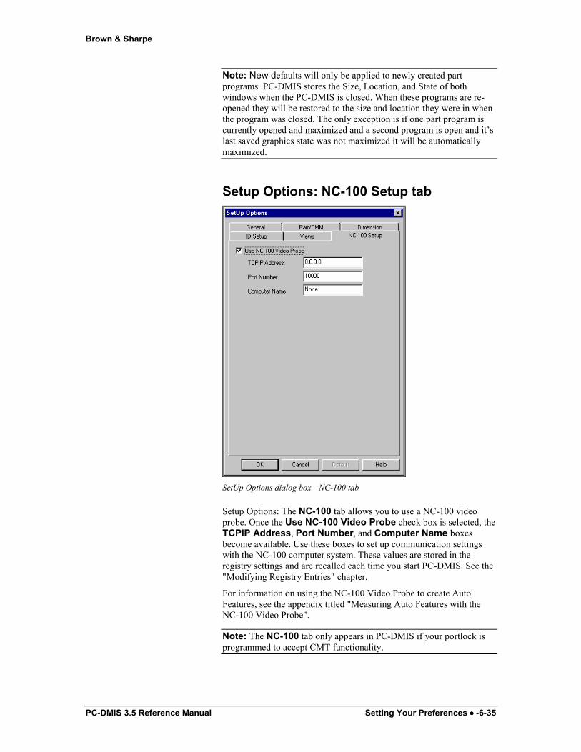
SetUp Options dialog box—NC-100 tab
Setup Options: The NC-100 tab allows you to use a NC-100 video probe. Once the Use NC-100 Video Probe check box is selected, the TCPIP Address, Port Number, and Computer Name boxes become available. Use these boxes to set up communication settings with the NC-100 computer system. These values are stored in the registry settings and are recalled each time you start PC-DMIS. See the "Modifying Registry Entries" chapter.
For information on using the NC-100 Video Probe to create Auto Features, see the appendix titled "Measuring Auto Features with the NC-100 Video Probe".
Note: The NC-100 tab only appears in PC-DMIS if your portlock is programmed to accept CMT functionality.
Brown & Sharpe
6-36 •••• Setting Your Preferences PC-DMIS 3.5 Reference Manual
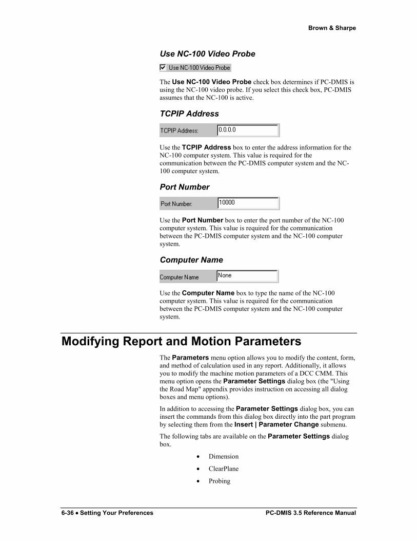
Use NC-100 Video Probe
The Use NC-100 Video Probe check box determines if PC-DMIS is using the NC-100 video probe. If you select this check box, PC-DMIS assumes that the NC-100 is active.
TCPIP Address
Use the TCPIP Address box to enter the address information for the NC-100 computer system. This value is required for the communication between the PC-DMIS computer system and the NC-100 computer system.
Port Number
Use the Port Number box to enter the port number of the NC-100 computer system. This value is required for the communication between the PC-DMIS computer system and the NC-100 computer system.
Computer Name
Use the Computer Name box to type the name of the NC-100 computer system. This value is required for the communication between the PC-DMIS computer system and the NC-100 computer system.
Modifying Report and Motion Parameters The Parameters menu option allows you to modify the content, form, and method of calculation used in any report. Additionally, it allows you to modify the machine motion parameters of a DCC CMM. This menu option opens the Parameter Settings dialog box (the "Using the Road Map" appendix provides instruction on accessing all dialog boxes and menu options).
In addition to accessing the Parameter Settings dialog box, you can insert the commands from this dialog box directly into the part program by selecting them from the Insert | Parameter Change submenu.
The following tabs are available on the Parameter Settings dialog box.
• Dimension
• ClearPlane
• Probing
Brown & Sharpe
PC-DMIS 3.5 Reference Manual Setting Your Preferences •••• -6-37
• Motion
• RoTable
• Acceleration
• Opt. Probe
• Probe Trigger Option
• NC-100 Parameters
• I/O Channels
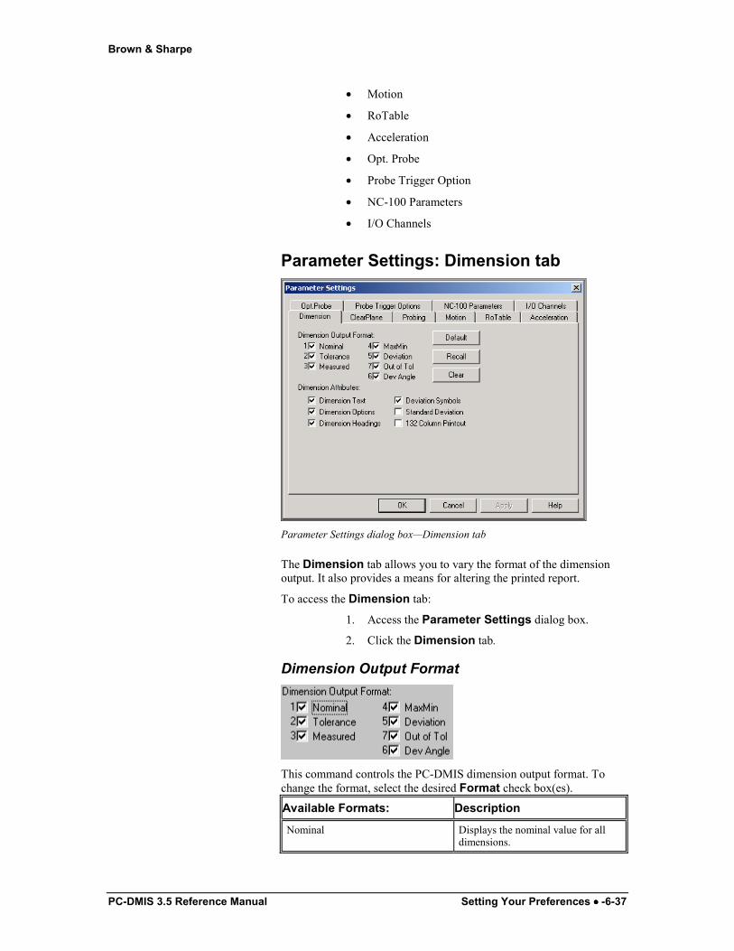
Parameter Settings: Dimension tab
Parameter Settings dialog box—Dimension tab
The Dimension tab allows you to vary the format of the dimension output. It also provides a means for altering the printed report.
To access the Dimension tab:
1. Access the Parameter Settings dialog box.
2. Click the Dimension tab.
Dimension Output Format
This command controls the PC-DMIS dimension output format. To change the format, select the desired Format check box(es).
Available Formats: Description
Nominal Displays the nominal value for all dimensions.
Brown & Sharpe
6-38 •••• Setting Your Preferences PC-DMIS 3.5 Reference Manual
Tolerance Displays the tolerance values for all dimensions.
Measured Displays the measured value for all dimensions.
MaxMin Displays the max and min values for all dimensions.
Deviation Displays the deviation value for all dimensions.
Out of Tol Displays the out of tolerance value for all dimensions.
Dev Angle Displays the deviation angle on the True Position dimensions.
When switching from box tolerancing to true position (and back), it is important to check the format for correctness.
PC-DMIS offers the same print formats for box tolerancing and true positioning tolerancing, although their columns will look slightly different due to additional columns for true position dimensions.
Example: When tolerancing the distance between two lines with the Max/Min check box selected, PC-DMIS will calculate the distance between the two points that were furthest apart or the two points that were closest together. It would then choose the worst case (most out of tolerance) of the two. If the Max/Min check box is not selected, PC-DMIS will calculate the dimension without displaying the Max/Min value.
PC-DMIS will indicate the order of the output selection by displaying a number to the right of the check box. This allows you to alter the order of the format to meet individual needs. A check box can be cleared simply by selecting it a second time.
The Edit window command line for this option reads:
FORMAT/TEXT,OPTIONS,HEADINGS,SYMBOLS, SD;"DIMENSION OUTPUT"
DIMENSION OUTPUT = The format of the output will be based on the order of selection. The default output will display the entire selection, in the order indicated.
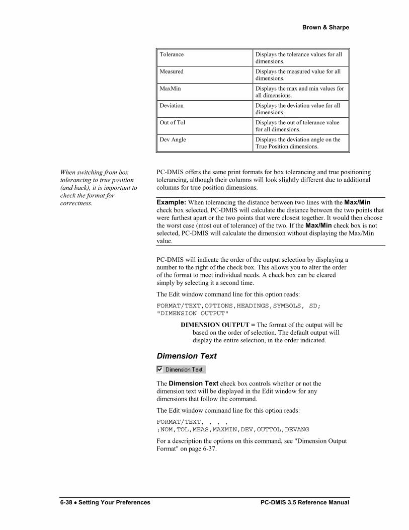
Dimension Text
The Dimension Text check box controls whether or not the dimension text will be displayed in the Edit window for any dimensions that follow the command.
The Edit window command line for this option reads:
FORMAT/TEXT, , , ,;NOM,TOL,MEAS,MAXMIN,DEV,OUTTOL,DEVANG
For a description the options on this command, see "Dimension Output Format" on page 6-37.

Brown & Sharpe
PC-DMIS 3.5 Reference Manual Setting Your Preferences •••• -6-39
Dimension Options
The Dimension Options check box controls whether or not the dimension options will be displayed in the Edit window for any dimensions that follow the command.
These options include:
• Units (see "Units" in the "Dimensioning Features" chapter)
• Graphical analysis (see "Analysis Settings" in the "Dimensioning Features" chapter)
• Textual analysis (see "Analysis Settings" in the "Dimensioning Features" chapter)
• Arrow multiplier (see "Analysis Settings" in the "Dimensioning Features" chapter)
• Output options (see "Analysis Settings" in the "Dimensioning Features" chapter)
The Edit window command line for this check box reads:
FORMAT/OPTIONS, , , ,;NOM,TOL,MEAS,MAXMIN,DEV,OUTTOL
Dimension Headings
The Dimension Headings check box controls the column headings on the inspection report. If this check box is not selected, then PC-DMIS will not print any column headings.
Deviation Symbols
The Deviation Symbols check box shows the deviation within the set range. If the out of tolerance range is high, PC-DMIS will indicate the deviation using the "greater than" symbol (>) on the right side of the line. If the out of tolerance range is low, PC-DMIS will indicate the deviation using the "less than" symbol (<).
For example: Nominal = 0.00 Measured = 0.02 Positive Tolerance = 0.10 Negative Tolerance = 0.20 Total Tolerance Range = (.10 - (-.20)) = .30 Percentage = 100*(.02 - (-.20))/.3 = 73.3 % - - - - - - # - - looks at the % and shifts based on the %.
DIM D1= LOCATION OF CIR F5 GRAPH=OFF TEXT=OFF MULT=1.00 AX NOM +TOL -TOL MEAS DEV OUT-TOL x 5.0000 0.0100 0.0100 5.0000 0.0000 0.0000 ----#---- y 2.0000 0.0100 0.0100 2.0000 0.0000 0.0000 ----#----
Brown & Sharpe
6-40 •••• Setting Your Preferences PC-DMIS 3.5 Reference Manual
z -0.2500 0.0100 0.0100 -0.2500 0.0000 0.0000 ----#---- d 2.0000 0.0100 0.0100 2.0000 0.0000 0.0000 v i j k
END OF DIMENSION D1
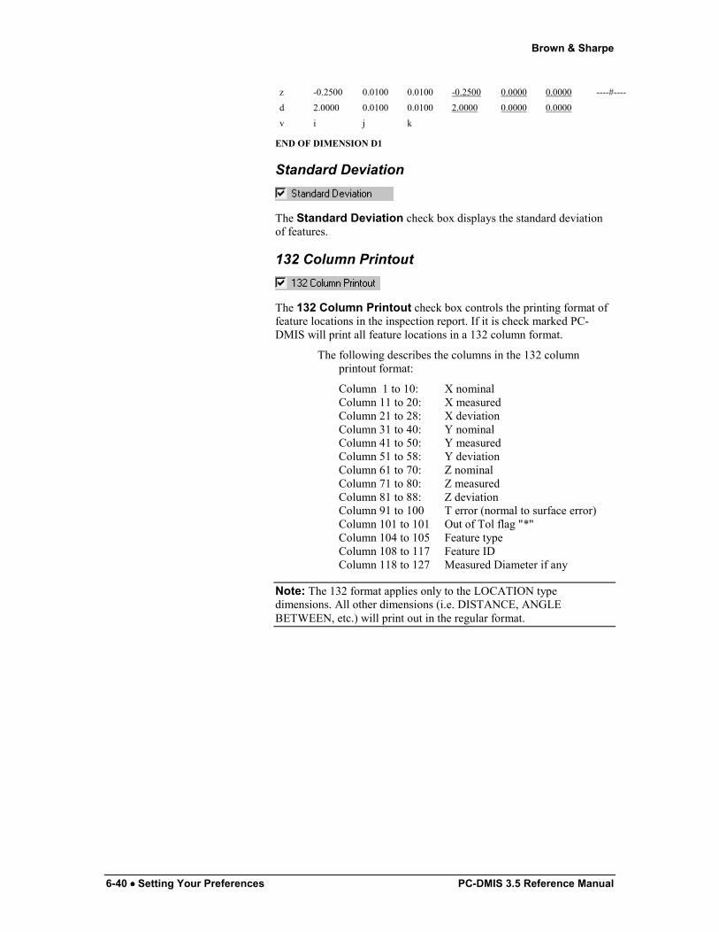
Standard Deviation
The Standard Deviation check box displays the standard deviation of features.
132 Column Printout
The 132 Column Printout check box controls the printing format of feature locations in the inspection report. If it is check marked PC-DMIS will print all feature locations in a 132 column format.
The following describes the columns in the 132 column printout format:
Column 1 to 10: X nominal Column 11 to 20: X measured Column 21 to 28: X deviation Column 31 to 40: Y nominal Column 41 to 50: Y measured Column 51 to 58: Y deviation Column 61 to 70: Z nominal Column 71 to 80: Z measured Column 81 to 88: Z deviation Column 91 to 100 T error (normal to surface error) Column 101 to 101 Out of Tol flag "*" Column 104 to 105 Feature type Column 108 to 117 Feature ID Column 118 to 127 Measured Diameter if any
Note: The 132 format applies only to the LOCATION type dimensions. All other dimensions (i.e. DISTANCE, ANGLE BETWEEN, etc.) will print out in the regular format.
Brown & Sharpe
PC-DMIS 3.5 Reference Manual Setting Your Preferences •••• -6-41
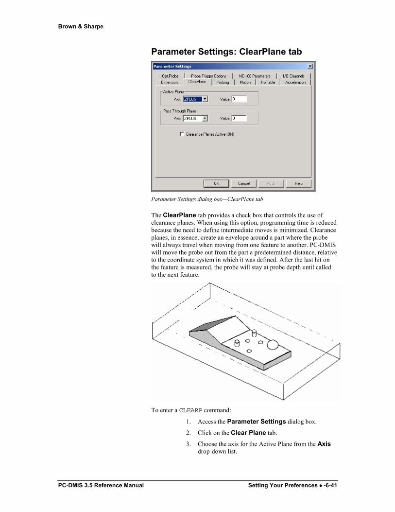
Parameter Settings: ClearPlane tab
Parameter Settings dialog box—ClearPlane tab
The ClearPlane tab provides a check box that controls the use of clearance planes. When using this option, programming time is reduced because the need to define intermediate moves is minimized. Clearance planes, in essence, create an envelope around a part where the probe will always travel when moving from one feature to another. PC-DMIS will move the probe out from the part a predetermined distance, relative to the coordinate system in which it was defined. After the last hit on the feature is measured, the probe will stay at probe depth until called to the next feature.
To enter a CLEARP command:
1. Access the Parameter Settings dialog box.
2. Click on the Clear Plane tab.
3. Choose the axis for the Active Plane from the Axis drop-down list.

Brown & Sharpe
6-42 •••• Setting Your Preferences PC-DMIS 3.5 Reference Manual
4. Type the distance away from the part in the Value box.
5. Choose the axis for the Pass Through Plane from the Axis drop-down list.
6. Type the distance of the Pass Through Plane in the Value box
7. Select the Clearance Plane Active (ON) check box.
8. Click the Apply button.
9. Click the OK button.
The Edit window command line for this option reads: CLEARP/ACTIVE_PLANE, .n,PASS_THROUGH_PLANE, .n
Active Plane
This area of the dialog box lets you indicate which plane the feature is in when it is measured. The Active Plane is also indicated in the Display drop-down list located on the toolbar.
PC-DMIS allows you to define a numerical value for the active main plane (X Plus, X Minus, Y Plus, Y Minus, Z Plus, and Z Minus). The Edit window will display the selected active window in a X, Y, Z PLUS or X, Y, Z MINUS direction. To define a clearance plane, first click on the drop-down list in the Active Plane area and select the desired plane to be changed. Then, enter a new value in the Value box.
Pass Through
This area of the dialog box lets you indicate the plane that the probe will pass through to get to the next feature plane.
PC-DMIS allows you to define numerical values for any of the six clearance planes:
1) X Plus
2) X Minus
3) Y Plus
4) Y Minus
5) Z Plus
6) Z Minus
The Edit window will display the selected active window in a X, Y, Z PLUS or X, Y, Z MINUS direction.
Brown & Sharpe
PC-DMIS 3.5 Reference Manual Setting Your Preferences •••• -6-43
To define a clearance plane:
1. Select the drop-down list on the Pass Through Plane area.
2. Select the desired plane to be changed.
3. Type the appropriate value in the Value box.
4. Click the Apply button.
5. Click the OK button.
Clearance Plane Active
The Clearance Plane Active (ON) check box activates the defined clearance plane.
Notes on Clearance Planes Movement from one clearance plane to another affects the position of the probe. Make sure that the set clearance plane is sufficient to clear the part.
It is important to be aware of the sign of a clearance plane when entering its value. The sign must correspond to the positive or negative end of the normal axis defining the plane. For example, to define a top clearance plane, enter a positive value, and to define a bottom clearance plane, enter a negative value.
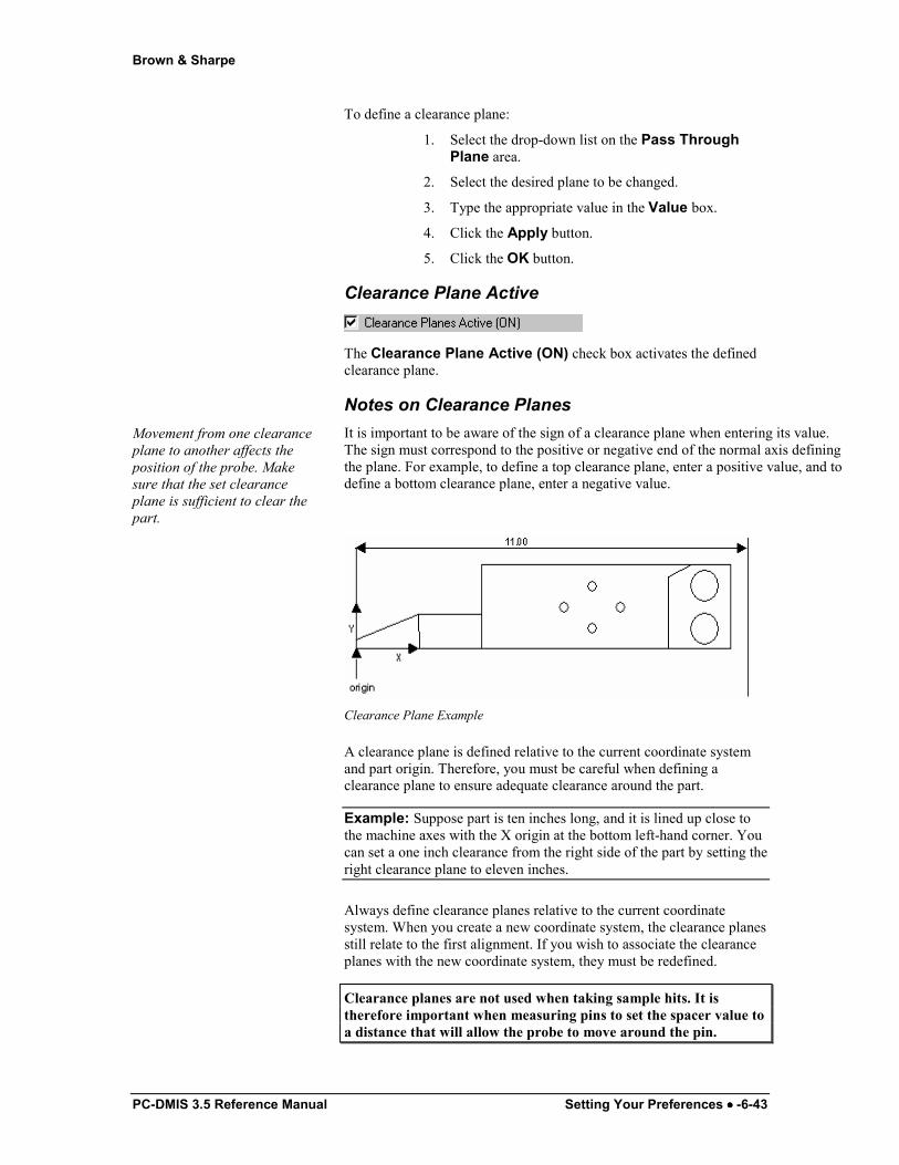
Clearance Plane Example
A clearance plane is defined relative to the current coordinate system and part origin. Therefore, you must be careful when defining a clearance plane to ensure adequate clearance around the part.
Example: Suppose part is ten inches long, and it is lined up close to the machine axes with the X origin at the bottom left-hand corner. You can set a one inch clearance from the right side of the part by setting the right clearance plane to eleven inches.
Always define clearance planes relative to the current coordinate system. When you create a new coordinate system, the clearance planes still relate to the first alignment. If you wish to associate the clearance planes with the new coordinate system, they must be redefined.
Clearance planes are not used when taking sample hits. It is therefore important when measuring pins to set the spacer value to a distance that will allow the probe to move around the pin.
Brown & Sharpe
6-44 •••• Setting Your Preferences PC-DMIS 3.5 Reference Manual
Parameter Settings: Probing tab
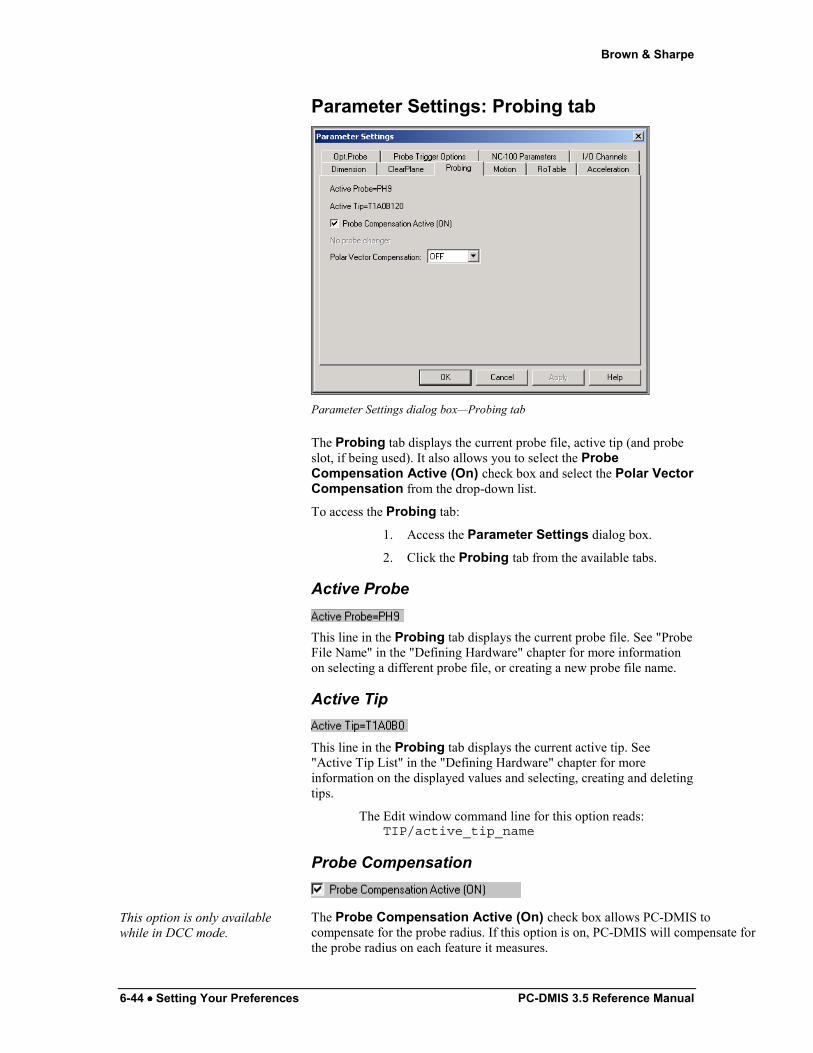
Parameter Settings dialog box—Probing tab
The Probing tab displays the current probe file, active tip (and probe slot, if being used). It also allows you to select the Probe Compensation Active (On) check box and select the Polar Vector Compensation from the drop-down list.
To access the Probing tab:
1. Access the Parameter Settings dialog box.
2. Click the Probing tab from the available tabs.
Active Probe
This line in the Probing tab displays the current probe file. See "Probe File Name" in the "Defining Hardware" chapter for more information on selecting a different probe file, or creating a new probe file name.
Active Tip
This line in the Probing tab displays the current active tip. See "Active Tip List" in the "Defining Hardware" chapter for more information on the displayed values and selecting, creating and deleting tips.
The Edit window command line for this option reads: TIP/active_tip_name
Probe Compensation
This option is only available while in DCC mode.
The Probe Compensation Active (On) check box allows PC-DMIS to compensate for the probe radius. If this option is on, PC-DMIS will compensate for the probe radius on each feature it measures.
Brown & Sharpe
PC-DMIS 3.5 Reference Manual Setting Your Preferences •••• -6-45
Command line in the Edit window: PROBECOM/ ON
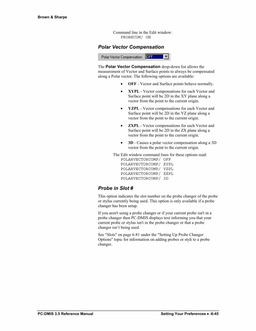
Polar Vector Compensation
The Polar Vector Compensation drop-down list allows the measurement of Vector and Surface points to always be compensated along a Polar vector. The following options are available:
• OFF - Vector and Surface points behave normally.
• XYPL - Vector compensations for each Vector and Surface point will be 2D in the XY plane along a vector from the point to the current origin.
• YZPL - Vector compensations for each Vector and Surface point will be 2D in the YZ plane along a vector from the point to the current origin.
• ZXPL - Vector compensations for each Vector and Surface point will be 2D in the ZX plane along a vector from the point to the current origin.
• 3D - Causes a polar vector compensation along a 3D vector from the point to the current origin.
The Edit window command lines for these options read: POLARVECTORCOMP/ OFFPOLARVECTORCOMP/ XYPLPOLARVECTORCOMP/ YZPLPOLARVECTORCOMP/ ZXPLPOLARVECTORCOMP/ 3D
Probe in Slot # This option indicates the slot number on the probe changer of the probe or stylus currently being used. This option is only available if a probe changer has been setup.
If you aren't using a probe changer or if your current probe isn't in a probe changer then PC-DMIS displays text informing you that your current probe or stylus isn't in the probe changer or that a probe changer isn’t being used.
See "Slots" on page 6-81 under the "Setting Up Probe Changer Options" topic for information on adding probes or styli to a probe changer.
Brown & Sharpe
6-46 •••• Setting Your Preferences PC-DMIS 3.5 Reference Manual
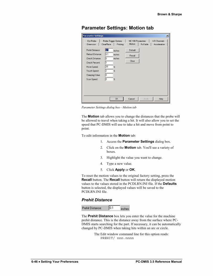
Parameter Settings: Motion tab
Parameter Settings dialog box—Motion tab
The Motion tab allows you to change the distances that the probe will be allowed to travel when taking a hit. It will also allow you to set the speed that PC-DMIS will use to take a hit and move from point to point.
To edit information in the Motion tab:
1. Access the Parameter Settings dialog box.
2. Click on the Motion tab. You'll see a variety of boxes.
3. Highlight the value you want to change.
4. Type a new value.
5. Click Apply or OK.
To reset the motion values to the original factory setting, press the Recall button. The Recall button will return the displayed motion values to the values stored in the PCDLRN.INI file. If the Defaults button is selected, the displayed values will be saved to the PCDLRN.INI file.
Prehit Distance
The Prehit Distance box lets you enter the value for the machine prehit distance. This is the distance away from the surface where PC-DMIS starts searching for the part. If necessary, it can be automatically changed by PC-DMIS when taking hits within an arc or circle.
The Edit window command line for this option reads: PREHIT/ nnn.nnnn
Brown & Sharpe
PC-DMIS 3.5 Reference Manual Setting Your Preferences •••• -6-47
Retract Distance
The Retract Distance box lets you enter the distance the probe retracts from the surface after taking a hit. If necessary, it can be automatically changed by PC-DMIS when taking hits on an arc or circle.
The Edit window command line for this option reads: RETRACT/ nnn.nnnn
Check Distance
The Check Distance box lets you enter the distance in either inches or millimeters (depending on the measurement system used for the part) past the theoretical hit location that the machine will continue to search for the surface of the part until it determines the surface is not there.
The Edit window command line for this option reads: CHECK/ distance,percentage
Percentage Movement During Find Hole Operations When defining the check distance for a Find Hole operation, you can tell PC-DMIS to move by a percentage of the check distance.
To do this:
1. Access the Edit window and place it in Command mode.
2. Click on the CHECK command in the Edit window.
3. Press the TAB key to move to the second number.
4. Type a new percentage value. The default value is 1 which means 100% of the check distance. Thus .1=10%, .2=20%, .3=30% etc.
For example, in the following code: CHECK/20,.3, the .3 value represents 30% of the total check distance of twenty units.
For additional information on Find Hole, see the "Find Hole Check Box" topic in the "Creating Auto Features" chapter:
Check Percent
The Check Percent value determines the percent of the total distance moved when performing a Find Hole operation. Be aware that if you type 1, the value is equal to 100 percent. Thus, 100% would be entered as 1, 25% would be entered as .25, and 10% would be .10.
Brown & Sharpe
6-48 •••• Setting Your Preferences PC-DMIS 3.5 Reference Manual
Move Speed %
The Move Speed box lets you change the point to point positioning speed of the CMM. The value that is entered is a percentage of the maximum machine speed. It can be set to any value between 1 and 100% of full machine speed. (See the "Measure" topic under "Defining Probes" in the "Defining Hardware" chapter for information regarding the move speed option and probe calibration.)
The Edit window command line for this option reads: MOVESPEED/ nnn.nnnn
Touch Speed %
The Touch Speed box lets you change the speed at which the CMM takes hits. The value that is entered is a percentage of the maximum machine speed, and cannot exceed twenty percent.
The Edit window command line for this option reads: TOUCHSPEED/ nnn.nnnn
To understand the effects of changing either PREHIT or RETRACT distances and MOVE or TOUCH SPEED, it's important to understand how the options interact during DCC feature measurement. The order of events is that the machine will move toward the feature at MOVE SPEED. When it reaches PREHIT distance, it will approach the feature at TOUCH SPEED to take the hit. After it takes the hit, it will back away at TOUCH SPEED until it reaches the RETRACT DISTANCE. At this point, it will go to the next location at MOVE SPEED.
Clamping Value
The Camping Value only works with the leitz controller and the leitz brand TTP. This value tells the controller how firmly to hold the probe on a Leitz CMM.
Depending on the weight of the probe tips, you may need to increase or decrease the clamping value.
• For a large tip weight, you may need to increase the clamping value.
• For a small tip weight, you may need to decrease the clamping value.
Scan Speed %
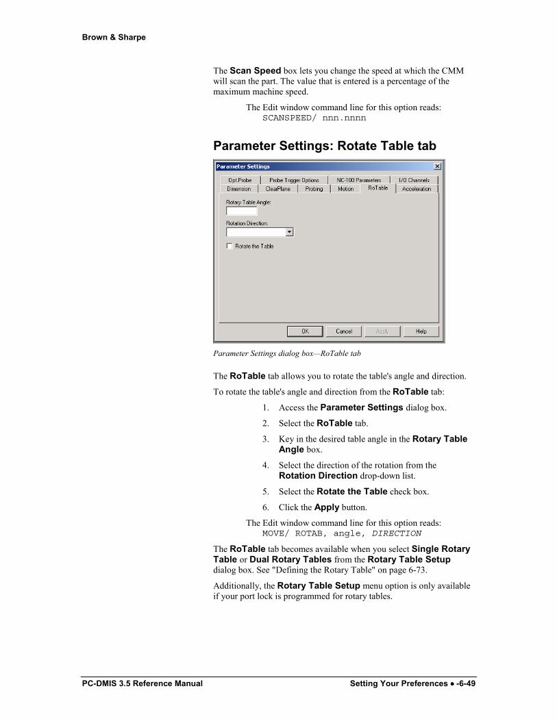
Brown & Sharpe
PC-DMIS 3.5 Reference Manual Setting Your Preferences •••• -6-49
The Scan Speed box lets you change the speed at which the CMM will scan the part. The value that is entered is a percentage of the maximum machine speed.
The Edit window command line for this option reads: SCANSPEED/ nnn.nnnn
Parameter Settings: Rotate Table tab
Parameter Settings dialog box—RoTable tab
The RoTable tab allows you to rotate the table's angle and direction.
To rotate the table's angle and direction from the RoTable tab:
1. Access the Parameter Settings dialog box.
2. Select the RoTable tab.
3. Key in the desired table angle in the Rotary Table Angle box.
4. Select the direction of the rotation from the Rotation Direction drop-down list.
5. Select the Rotate the Table check box.
6. Click the Apply button.
The Edit window command line for this option reads: MOVE/ ROTAB, angle, DIRECTION
The RoTable tab becomes available when you select Single Rotary Table or Dual Rotary Tables from the Rotary Table Setup dialog box. See "Defining the Rotary Table" on page 6-73.
Additionally, the Rotary Table Setup menu option is only available if your port lock is programmed for rotary tables.

Brown & Sharpe
6-50 •••• Setting Your Preferences PC-DMIS 3.5 Reference Manual
Rotate Table Angle
In the Rotary Table Angle box you can type the angle of the table's rotation.
Rotation Direction
In the Rotation Direction drop down list you can select the direction you want the table to rotate. Available options are: Clockwise: Rotates the table in a clockwise
direction until it reaches the angle entered in the Rotate Table Angle box.
Counterclockwise: Rotates the table in a counterclockwise direction until it reaches the angle entered in the Rotate Table Angle box.
Shortest: Rotates taking the shortest route (either Clockwise or Counterclockwise) until it reaches the angle entered in the Rotate Table Angle box.
Rotate the Table
The Rotate the Table check box allows the table rotation to be activated once either the Apply or the OK button is pressed.
Parameter Settings: Optional Motion tab

Brown & Sharpe
PC-DMIS 3.5 Reference Manual Setting Your Preferences •••• -6-51
Parameter Settings dialog box—Acceleration tab
The Acceleration tab displays additional editing capabilities for both CMM and Table motion.
To access the Acceleration tab:
1. Access the Parameter Settings dialog box from the main menu.
2. Select the Acceleration tab.
CMM Acceleration
The CMM Acceleration area of the Acceleration tab allows you to change what the maximum acceleration would be along the X, Y, or Z axis of the CMM. Available options are: Maximum X Axis Acceleration: The number in this box represents the
maximum acceleration that the CMM will take when traveling along the X axis.
Maximum Y Axis Acceleration: The number in this box represents the maximum acceleration that the CMM will take when traveling along the Y axis.
Maximum Z Axis Acceleration: The number in this box represents the maximum acceleration that the CMM will take when traveling along the Z axis.
Parameter Settings: Optional Probe tab
Parameter Settings dialog box—Opt. Probe tab
Brown & Sharpe
6-52 •••• Setting Your Preferences PC-DMIS 3.5 Reference Manual
The Opt. Probe tab gives you additional capabilities for controlling analog probes. These capabilities include the following probing related values:
• Max Force
• Low Force
• Upper Force
• Trigger Force
• # Return Data
• Return Speed
• Positioning Accuracy
• Probing Accuracy
• Probing Mode
• Manual Fine Probing
It also includes the following Scan related values and general purpose buttons:
• Point Density
• Offset Force
• Acceleration
• Default button
• Recall button
• Clear button
Each of these is described below in greater detail.
To access the Opt. Probe tab:
1. Access the Parameter Settings dialog box from the main menu.
2. Select the Opt. Probe tab.
Max Force
The Max Force box allows you to enter the maximum force that a probe will take before an error will occur thus stopping measurement.
A "newton" is a unit of force. One newton is the force needed to accelerate a mass of 1 kilogram to a speed of 1 metre per second per second.
During an analog probing cycle, when the probe first touches the part it continues to move into the part until it reaches this Max Force value. It then reverses direction and moves away from the part. This movement into the part, after touching the part, is sometimes referred to as the contact force. The value is specified in newtons. In a normal deflection mode (DFL) probing cycle, the controller collects data as the probe moves away from the part.
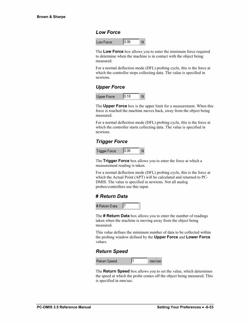
Brown & Sharpe
PC-DMIS 3.5 Reference Manual Setting Your Preferences •••• -6-53
Low Force
The Low Force box allows you to enter the minimum force required to determine when the machine is in contact with the object being measured.
For a normal deflection mode (DFL) probing cycle, this is the force at which the controller stops collecting data. The value is specified in newtons.
Upper Force
The Upper Force box is the upper limit for a measurement. When this force is reached the machine moves back, away from the object being measured.
For a normal deflection mode (DFL) probing cycle, this is the force at which the controller starts collecting data. The value is specified in newtons.
Trigger Force
The Trigger Force box allows you to enter the force at which a measurement reading is taken.
For a normal deflection mode (DFL) probing cycle, this is the force at which the Actual Point (APT) will be calculated and returned to PC-DMIS. The value is specified in newtons. Not all analog probes/controllers use this input.
# Return Data
The # Return Data box allows you to enter the number of readings taken when the machine is moving away from the object being measured.
This value defines the minimum number of data to be collected within the probing window defined by the Upper Force and Lower Force values.
Return Speed
The Return Speed box allows you to set the value, which determines the speed at which the probe comes off the object being measured. This is specified in mm/sec.
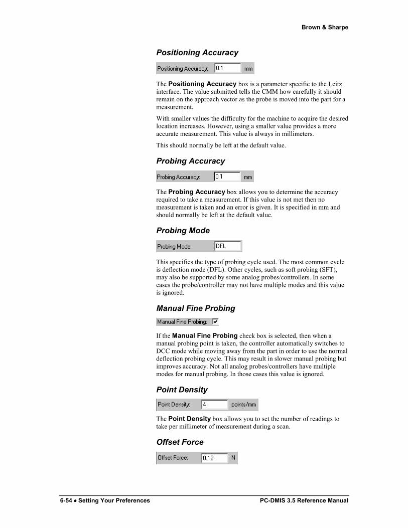
Brown & Sharpe
6-54 •••• Setting Your Preferences PC-DMIS 3.5 Reference Manual
Positioning Accuracy
The Positioning Accuracy box is a parameter specific to the Leitz interface. The value submitted tells the CMM how carefully it should remain on the approach vector as the probe is moved into the part for a measurement.
With smaller values the difficulty for the machine to acquire the desired location increases. However, using a smaller value provides a more accurate measurement. This value is always in millimeters.
This should normally be left at the default value.
Probing Accuracy
The Probing Accuracy box allows you to determine the accuracy required to take a measurement. If this value is not met then no measurement is taken and an error is given. It is specified in mm and should normally be left at the default value.
Probing Mode
This specifies the type of probing cycle used. The most common cycle is deflection mode (DFL). Other cycles, such as soft probing (SFT), may also be supported by some analog probes/controllers. In some cases the probe/controller may not have multiple modes and this value is ignored.
Manual Fine Probing
If the Manual Fine Probing check box is selected, then when a manual probing point is taken, the controller automatically switches to DCC mode while moving away from the part in order to use the normal deflection probing cycle. This may result in slower manual probing but improves accuracy. Not all analog probes/controllers have multiple modes for manual probing. In those cases this value is ignored.
Point Density
The Point Density box allows you to set the number of readings to take per millimeter of measurement during a scan.
Offset Force
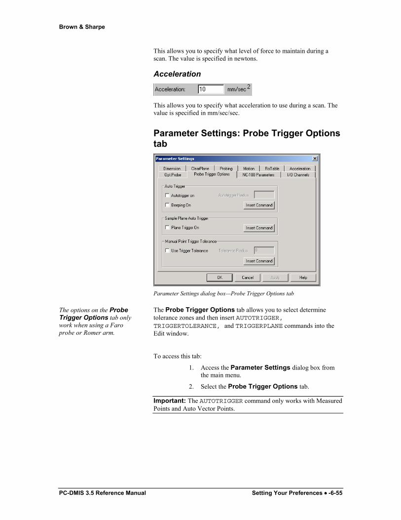
Brown & Sharpe
PC-DMIS 3.5 Reference Manual Setting Your Preferences •••• -6-55
This allows you to specify what level of force to maintain during a scan. The value is specified in newtons.
Acceleration
This allows you to specify what acceleration to use during a scan. The value is specified in mm/sec/sec.
Parameter Settings: Probe Trigger Options tab
Parameter Settings dialog box—Probe Trigger Options tab
The options on the Probe Trigger Options tab only work when using a Faro probe or Romer arm.
The Probe Trigger Options tab allows you to select determine tolerance zones and then insert AUTOTRIGGER,TRIGGERTOLERANCE, and TRIGGERPLANE commands into the Edit window.
To access this tab:
1. Access the Parameter Settings dialog box from the main menu.
2. Select the Probe Trigger Options tab.
Important: The AUTOTRIGGER command only works with Measured Points and Auto Vector Points.

Brown & Sharpe
6-56 •••• Setting Your Preferences PC-DMIS 3.5 Reference Manual
Auto Trigger area
With the Auto Trigger area you can insert AUTOTRIGGER/ commands into the Edit window with a tolerance zone.
The AUTOTRIGGER/ command tells PC-DMIS to automatically take a hit when the probe enters a tolerance zone at a specified distance from the original hit location. For example, if the tolerance zone is set to 2mm, a hit is taken when the probe is within 2mm of the hit location.
You can use this option with manual machines; instead of pressing a button to take a hit, you can place AUTOTRIGGER/ commands at any standard location in the Edit window.
This option only works in online mode.
Autotrigger On
Selecting the Autotrigger On check box activates the autotrigger command. Commands in the Edit window that follow the inserted AUTOTRIGGER/ command and require you to take a hit will then have the hit automatically taken when the probe enters the defined tolerance zone.
If you do not select this check box and you click the Insert Command button, PC-DMIS inserts the command line into the Edit window but doesn't activate the command.
Beeping On
Selecting the Beeping On check box activates a beeping sound associated with your AUTOTRIGGER/ command. The closer you get to the target, the more frequent the beeps.
Autotrigger Radius
The Autotrigger Radius box allows you to type a tolerance zone value. When the probe moves into this tolerance zone, it automatically and immediately takes a hit.
Insert Command
Clicking the Insert Command button inserts the AUTOTRIGGER/ command into the Edit window for the current part program. This command line reads:
AUTOTRIGGER/ TOG1, TOG2, RAD

Brown & Sharpe
PC-DMIS 3.5 Reference Manual Setting Your Preferences •••• -6-57
TOG1 This toggle field corresponds to the Autotrigger On check box. It displays either ON or OFF.
TOG2 This toggle field corresponds to the Beeping On check box. It displays either ON or OFF.
RAD The radius field contains the value for the tolerance zone. This value is the distance from the actual point that PC-DMIS takes the hit.
Sample Plane Auto Trigger area
With the Sample Plane Auto Trigger area you can insert a TRIGGERPLANE/ command into the Edit window.
The TRIGGERPLANE/ command only works for Auto Circles, Auto Ellipses, Auto Slots, and Auto Edge Points.
The TRIGGERPLANE/ command tells PC-DMIS to automatically take a hit when the probe passes the plane defined by the surface normal of an auto feature at the level of the defined depth. This defined location will be adjusted based on options such as sample hits or RMEAS features. As the probe center passes from one side of the plane to the other the probe will trigger and the hit will be taken.
You can use this command with manual machines; instead of pressing a button to take a hit, you can place TRIGGERPLANE/ commands at any standard location within the Edit window.
This command only works in online mode. If the AUTOTRIGGER/ command is used, it will take precedence over the TRIGGERPLANE/ command.
Note on Faro and Romer Machines: As defined above, PC-DMIS will automatically take a hit when the probe passes the plane. However, if you are using a Faro or a Romer machine, the probe will not trigger again until you press the Accept button (or Release button). You must press this button after each registered hit in order to continue.
Plane Trigger On
Selecting the Plane Trigger On check box activates the TRIGGERPLANE/ command. Commands in the Edit window that follow the inserted TRIGGERPLANE/ command and require you to take a hit will then have the hit automatically taken when the probe center passes the plane defined by the surface normal and depth of the feature.
If you do not select this check box and you click the Insert Command button, PC-DMIS inserts the command line into the Edit window but doesn't activate the command. The TRIGGERPLANE/ command will not function until the option is turned on.
Insert Command

Brown & Sharpe
6-58 •••• Setting Your Preferences PC-DMIS 3.5 Reference Manual
Clicking the Insert Command button inserts the triggerplane command into the Edit window for the current part program.
TRIGGERPLANE/ TOG1
TOG1 This toggle field corresponds to the Plane Trigger On check box. It displays either ON or OFF.
Manual Point Trigger Tolerance area
With the Manual Point Trigger Tolerance area you can insert a TRIGGERTOLERANCE/ command into the Edit window.
This command only works in conjunction with auto point feature types: Vector Point, Surface Point, Angle Point, Corner Point, and Measure Point. It does not work on the individual hits of features.
The TRIGGERTOLERANCE/ command tells PC-DMIS to only accept a manual hit when it is within the specified tolerance zone.
You can use this option with manual machines; when PC-DMIS prompts you to take a hit, trigger the probe as you wish. Each trigger will be evaluated to see if it is within the cylindrical trigger tolerance zone. If it is not, you will receive an error in the CMM Errors list of the Execution Mode Options dialog box. PC-DMIS will then ask you to take the hit again. You can place TRIGGERTOLERANCE/ commands at any standard location within the Edit window.
This option only works in online mode.
Use Trigger Tolerance
Selecting the Use Trigger Tolerance check box activates the TRIGGERTOLERANCE/ command . Commands in the Edit window that follow the inserted TRIGGERTOLERANCE/ command and require you to take a hit will then only accept the hit when the probe enters the defined tolerance zone.
If you do not select this check box and you click the Insert Command button, PC-DMIS inserts the command line into the Edit window but doesn't activate the command. The Trigger Tolerance capability is disabled until the option is turned on
Insert Command
Clicking the Insert Command button inserts the TRIGGERTOLERANCE/ command into the Edit window for the current part program with the following options.
TRIGGERTOLERANCE/ TOG1, RAD
TOG1 This toggle field corresponds to the Use Trigger Tolerance check box. It displays either ON or OFF.
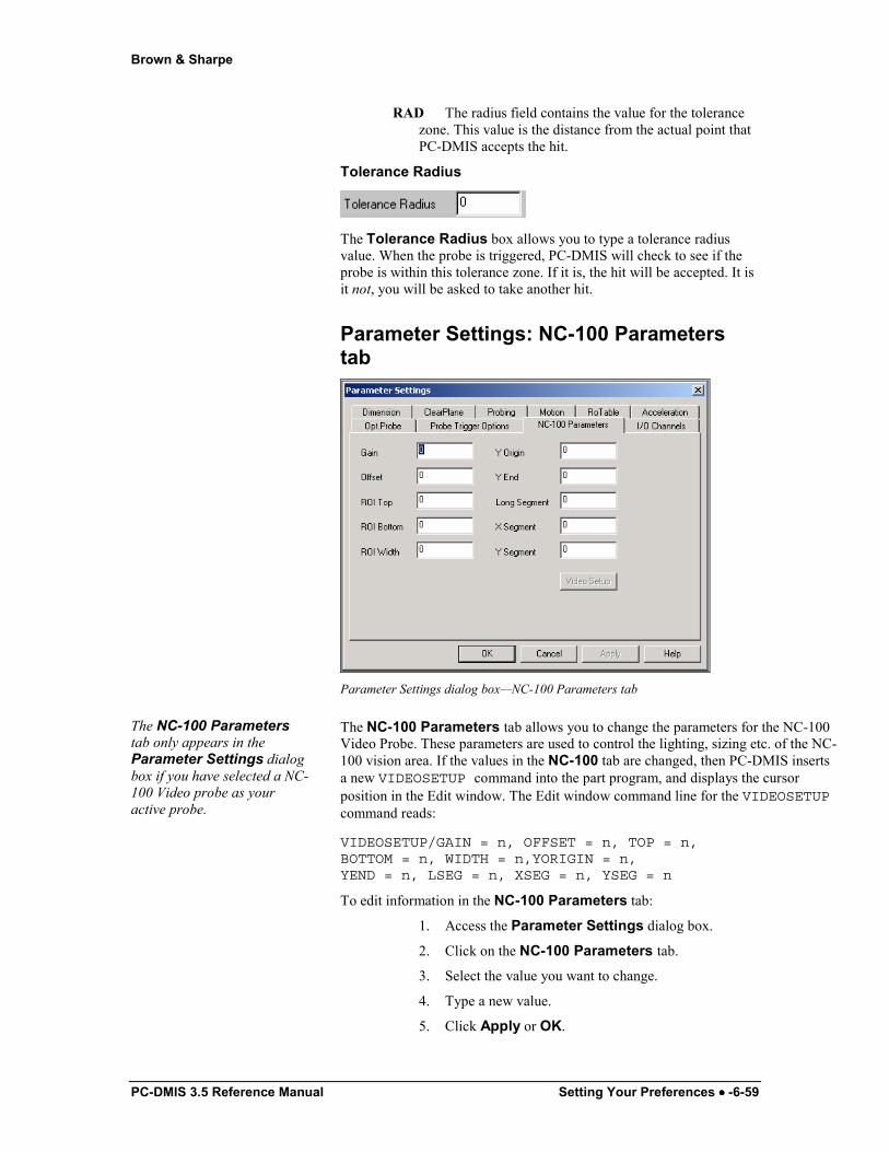
Brown & Sharpe
PC-DMIS 3.5 Reference Manual Setting Your Preferences •••• -6-59
RAD The radius field contains the value for the tolerance zone. This value is the distance from the actual point that PC-DMIS accepts the hit.
Tolerance Radius
The Tolerance Radius box allows you to type a tolerance radius value. When the probe is triggered, PC-DMIS will check to see if the probe is within this tolerance zone. If it is, the hit will be accepted. It is it not, you will be asked to take another hit.
Parameter Settings: NC-100 Parameters tab
Parameter Settings dialog box—NC-100 Parameters tab
The NC-100 Parameters tab only appears in the Parameter Settings dialog box if you have selected a NC-100 Video probe as your active probe.
The NC-100 Parameters tab allows you to change the parameters for the NC-100 Video Probe. These parameters are used to control the lighting, sizing etc. of the NC-100 vision area. If the values in the NC-100 tab are changed, then PC-DMIS inserts a new VIDEOSETUP command into the part program, and displays the cursor position in the Edit window. The Edit window command line for the VIDEOSETUP command reads:
VIDEOSETUP/GAIN = n, OFFSET = n, TOP = n,BOTTOM = n, WIDTH = n,YORIGIN = n,YEND = n, LSEG = n, XSEG = n, YSEG = n
To edit information in the NC-100 Parameters tab:
1. Access the Parameter Settings dialog box.
2. Click on the NC-100 Parameters tab.
3. Select the value you want to change.
4. Type a new value.
5. Click Apply or OK.
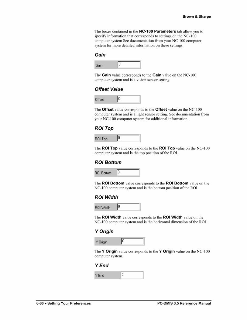
Brown & Sharpe
6-60 •••• Setting Your Preferences PC-DMIS 3.5 Reference Manual
The boxes contained in the NC-100 Parameters tab allow you to specify information that corresponds to settings on the NC-100 computer system See documentation from your NC-100 computer system for more detailed information on these settings.
Gain
The Gain value corresponds to the Gain value on the NC-100 computer system and is a vision sensor setting.
Offset Value
The Offset value corresponds to the Offset value on the NC-100 computer system and is a light sensor setting. See documentation from your NC-100 computer system for additional information.
ROI Top
The ROI Top value corresponds to the ROI Top value on the NC-100 computer system and is the top position of the ROI.
ROI Bottom
The ROI Bottom value corresponds to the ROI Bottom value on the NC-100 computer system and is the bottom position of the ROI.
ROI Width
The ROI Width value corresponds to the ROI Width value on the NC-100 computer system and is the horizontal dimension of the ROI.
Y Origin
The Y Origin value corresponds to the Y Origin value on the NC-100 computer system.
Y End

Brown & Sharpe
PC-DMIS 3.5 Reference Manual Setting Your Preferences •••• -6-61
The Y End value corresponds to the Y End value on the NC-100 computer system.
Long Segment
The Long Segment value corresponds to the Long Segment value on the NC-100 computer system.
X Segment
The X Segment value corresponds to the X Segment value on the NC-100 computer system.
Y Segment
The Y Segment value corresponds to the Y Segment value on the NC-100 computer system.
Video Setup
The Video Setup button allows you to open the Video Setup Parameters on the NC-100 Video System. Clicking this button opens and closes this option.
Communication settings between the PC-DMIS computer system and the NC-100 computer system have to be configured before this option functions properly. See "NC-100 Setup" on the SetUp Options dialog box for this information.
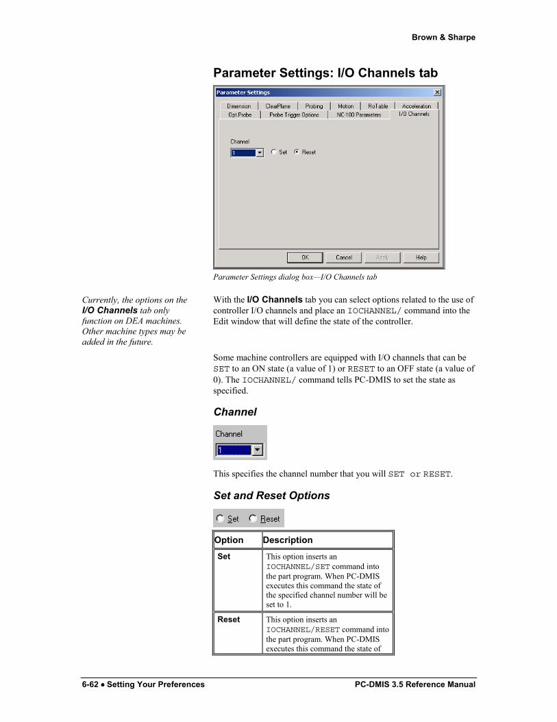
Brown & Sharpe
6-62 •••• Setting Your Preferences PC-DMIS 3.5 Reference Manual
Parameter Settings: I/O Channels tab
Parameter Settings dialog box—I/O Channels tab
Currently, the options on the I/O Channels tab only function on DEA machines. Other machine types may be added in the future.
With the I/O Channels tab you can select options related to the use of controller I/O channels and place an IOCHANNEL/ command into the Edit window that will define the state of the controller.
Some machine controllers are equipped with I/O channels that can be SET to an ON state (a value of 1) or RESET to an OFF state (a value of 0). The IOCHANNEL/ command tells PC-DMIS to set the state as specified.
Channel
This specifies the channel number that you will SET or RESET.
Set and Reset Options
Option Description Set This option inserts an
IOCHANNEL/SET command into the part program. When PC-DMIS executes this command the state of the specified channel number will be set to 1.
Reset This option inserts an IOCHANNEL/RESET command into the part program. When PC-DMIS executes this command the state of

Brown & Sharpe
PC-DMIS 3.5 Reference Manual Setting Your Preferences •••• -6-63
the specified channel number will be set to 0.
Setting Up the Edit Window PC-DMIS lets you determine the Edit window's appearance as well as what information to display within some the Edit window's modes.
Defining Edit Window Colors
Edit Window Colors dialog box
The Edit Window Colors menu option allows configuration of the colors used to differentiate text displayed by the Edit window. There are four principal colors that can be configured.
1.) Standard
2.) Out-of-Tolerance
3.) Marked
4.) Debug
You can also change background colors for the Edit window and for dimensions.
Standard Color: Standard Color is the default color. If no other condition is present then the default color is used.
Out-of-Tolerance: Out-of-Tolerance color shows measurements that are outside of their tolerance limits. Out-of-Tolerance color is also used to indicate if some feature in the Edit window is not fully defined. For example, if a tip is recalled but is not defined in the probe database, this tip text will be colored with the Out-of-Tolerance color.
Marked Color: Marked Color represents any feature that is marked for execution. Some features such as alignments are always executed and therefore always show up in the Marked
Brown & Sharpe
6-64 •••• Setting Your Preferences PC-DMIS 3.5 Reference Manual
color. Debug Color: Debug Color highlights the line upon
which execution will occur next when executing a part program using breakpoints.
Background Color: Background Color of the Edit window can also be modified from within this dialog.
Dimension Background Color
Dimension Background Color sets the background color for a dimension's reporting boxes displayed in Report mode.
To change the colors used: 1. Select Edit Window Colors from the menu bar.
The Edit Window Colors dialog box opens.
2. Simply click the Edit button for the text or background color you want to change. A Color selection box will appear
3. Select the new color, or customize a color by selecting the Define Custom Colors button.
4. Click the OK button. The Color selection box will close.
5. Click the Apply button to see the changes without closing the Colors dialog box.
6. Click the OK button to apply the changes and close the Edit Window Colors dialog box.
The color changes will immediately be made.
Defining the Edit window Layout The Edit Window Layout menu option brings up the tabbed Edit Window Layout dialog box. The dialog box contains the following tabs:
• Command
• Report
• Hyper-Report
These tabs let you specify the features (or dimensions) that will be displayed in the Edit window, printed in the Edit report, and options for the Hyper-Report and the Summary mode are also available from this dialog box.
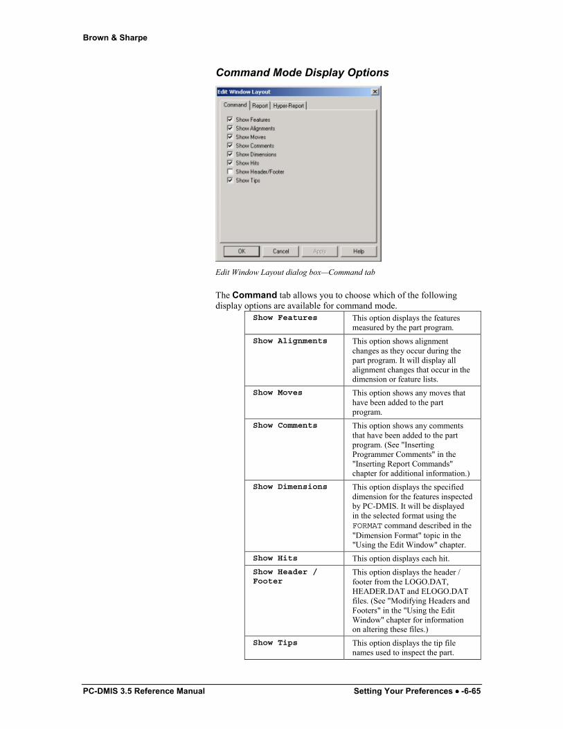
Brown & Sharpe
PC-DMIS 3.5 Reference Manual Setting Your Preferences •••• -6-65
Command Mode Display Options
Edit Window Layout dialog box—Command tab
The Command tab allows you to choose which of the following display options are available for command mode.
Show Features This option displays the features measured by the part program.
Show Alignments This option shows alignment changes as they occur during the part program. It will display all alignment changes that occur in the dimension or feature lists.
Show Moves This option shows any moves that have been added to the part program.
Show Comments This option shows any comments that have been added to the part program. (See "Inserting Programmer Comments" in the "Inserting Report Commands" chapter for additional information.)
Show Dimensions This option displays the specified dimension for the features inspected by PC-DMIS. It will be displayed in the selected format using the FORMAT command described in the "Dimension Format" topic in the "Using the Edit Window" chapter.
Show Hits This option displays each hit. Show Header /Footer
This option displays the header / footer from the LOGO.DAT, HEADER.DAT and ELOGO.DAT files. (See "Modifying Headers and Footers" in the "Using the Edit Window" chapter for information on altering these files.)
Show Tips This option displays the tip file names used to inspect the part.
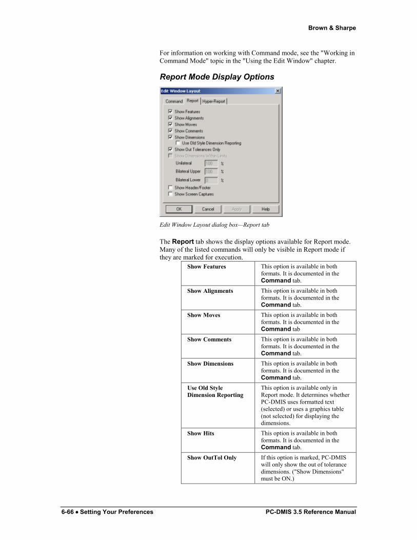
Brown & Sharpe
6-66 •••• Setting Your Preferences PC-DMIS 3.5 Reference Manual
For information on working with Command mode, see the "Working in Command Mode" topic in the "Using the Edit Window" chapter.
Report Mode Display Options
Edit Window Layout dialog box—Report tab
The Report tab shows the display options available for Report mode. Many of the listed commands will only be visible in Report mode if they are marked for execution.
Show Features This option is available in both formats. It is documented in the Command tab.
Show Alignments This option is available in both formats. It is documented in the Command tab.
Show Moves This option is available in both formats. It is documented in the Command tab
Show Comments This option is available in both formats. It is documented in the Command tab.
Show Dimensions This option is available in both formats. It is documented in the Command tab.
Use Old Style Dimension Reporting
This option is available only in Report mode. It determines whether PC-DMIS uses formatted text (selected) or uses a graphics table (not selected) for displaying the dimensions.
Show Hits This option is available in both formats. It is documented in the Command tab.
Show OutTol Only If this option is marked, PC-DMIS will only show the out of tolerance dimensions. ("Show Dimensions" must be ON.)
Brown & Sharpe
PC-DMIS 3.5 Reference Manual Setting Your Preferences •••• -6-67
This option is only available when you select Show Dimensions and deselect Show Dimensions Within Limits.
Show Dimensions Within Limits
If you select this option, PC-DMIS will only show the dimensions that lie outside the percentage of the tolerance zone. This option is only available when you select Show Dimensions and deselect Show OutTol Only. When you select the Show Dimensions Within Limits check box, the tolerance percentages will become editable, allowing one percentage for unilateral tolerances and an upper and lower percentage for bilateral tolerances.
The tolerance zone can be considered as a range between 0 and 100 percent (similar to how dimension colors are applied to tolerance zone regions or how the colored bar graphs are drawn at the end of dimensions). Dimensions that have deviations outside the tolerance zone will either be less than zero or greater than one hundred percent.
For a unilateral dimension (like roundness, which only has a plus tolerance), the zero deviations are at zero percent, and out of tolerance is anything larger than one hundred percent.
For a bilateral dimension (like distance, which has both a plus and minus tolerance), the zero deviations are somewhere in the middle. If the tolerances are equal, the zero deviations will be at the fifty percent position.
Show Dimension Within Limits - Unilateral Example Unilateral Percentage:
Nominal: 0.0000
Measured: 0.0028
Deviation: 0.0028 Plus Tol: 0.0050 Minus Tol: 0.0000
Because this deviation is 56% of the tolerance range, it will be displayed if Unilateral Percentage is less than 56%.
Show Dimension Within Limits – Bilateral Upper Example Bilateral Upper Percentage:
Nominal: 3.0000 Measured: 3.0075
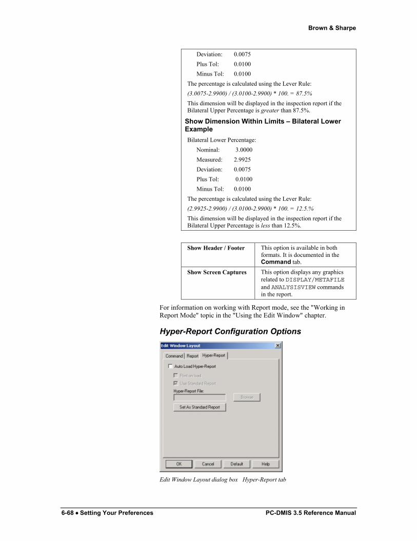
Brown & Sharpe
6-68 •••• Setting Your Preferences PC-DMIS 3.5 Reference Manual
Deviation: 0.0075 Plus Tol: 0.0100 Minus Tol: 0.0100
The percentage is calculated using the Lever Rule: (3.0075-2.9900) / (3.0100-2.9900) * 100. = 87.5% This dimension will be displayed in the inspection report if the Bilateral Upper Percentage is greater than 87.5%.
Show Dimension Within Limits – Bilateral Lower Example Bilateral Lower Percentage:
Nominal: 3.0000 Measured: 2.9925 Deviation: 0.0075 Plus Tol: 0.0100 Minus Tol: 0.0100
The percentage is calculated using the Lever Rule: (2.9925-2.9900) / (3.0100-2.9900) * 100. = 12.5.% This dimension will be displayed in the inspection report if the Bilateral Upper Percentage is less than 12.5%.
Show Header / Footer This option is available in both
formats. It is documented in the Command tab.
Show Screen Captures This option displays any graphics related to DISPLAY/METAFILEand ANALYSISVIEW commands in the report.
For information on working with Report mode, see the "Working in Report Mode" topic in the "Using the Edit Window" chapter.
Hyper-Report Configuration Options
Edit Window Layout dialog box�Hyper-Report tab
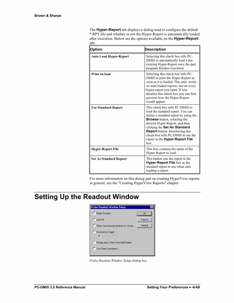
Brown & Sharpe
PC-DMIS 3.5 Reference Manual Setting Your Preferences •••• -6-69
The Hyper-Report tab displays a dialog used to configure the default *.RPT file and whether or not the Hyper-Report is automatically loaded after execution. Below are the options available on the Hyper-Report tab:
Option Description
Auto Load Hyper-Report Selecting this check box tells PC-DMIS to automatically load a pre-existing Hyper-Report once the part program finishes execution.
Print on load Selecting this check box tells PC-DMIS to print the Hyper-Report as soon as it is loaded. This only works on auto loaded reports, not on every hyper-report you open. If you deselect this check box you can first preview how the Hyper-Report would appear.
Use Standard Report This check box tells PC-DMIS to load the standard report. You can define a standard report by using the Browse button, selecting the desired Hyper-Report, and then clicking the Set As Standard Report button. Deselecting this check box tells PC-DMIS to use the report in the Hyper-Report File box.
Hyper-Report File This box contains the name of the Hyper-Report to load.
Set As Standard Report This button sets the report in the Hyper-Report File box as the standard report to use when auto loading a report.
For more information on this dialog and on creating HyperView reports in general, see the "Creating HyperView Reports" chapter.
Setting Up the Readout Window
Probe Readout Window Setup dialog box
Brown & Sharpe
6-70 •••• Setting Your Preferences PC-DMIS 3.5 Reference Manual
The Probe Readout Window Setup dialog box allows you to select the desired format of the Probe Readout window. Select the check boxes that meet your probe readout needs. When you next select the Probe Readout Window menu option it will reflect the chosen format.
For information on using the Probe Readout window, see "Using the Probe Readout window" in the "Using Other Windows and Editors" chapter.
Probe Position
When you select the Probe Position check box, PC-DMIS displays the current position of the probe. The Probe Readout window will display the probe's position in the active coordinate system.
Last Hit
When you select the Last Hit check box, PC-DMIS will display the location of the last hit taken with the probe. If this option is not selected, PC-DMIS displays the current position of the probe.
Show Current Probe Position on Screen
The Show Current Probe Position on Screen check box differs from the Probe Position check box in that it shows a graphical representation of the probe on screen, relative to the machine. This is helpful when working on-line. When you move the probe by using the jog box, a graphical representation of the probe also moves within PC-DMIS'S screen.
Distance to Target
When you select the Distance to Target check box, PC-DMIS displays the distance of the probe to the target point. The probe's position is displayed in the active coordinate system. Manually drive the probe to the keyed in location. When the target point is reached, the Probe Readout window will display 0,0,0.
Distance to Target with Auto Zoom
When you select both the Distance to Target check box and the With Auto Zoom check box, PC-DMIS also displays the distance of the probe to the target point. The probe’s position is displayed in the active coordinate system. As the probe is manually driven to the keyed
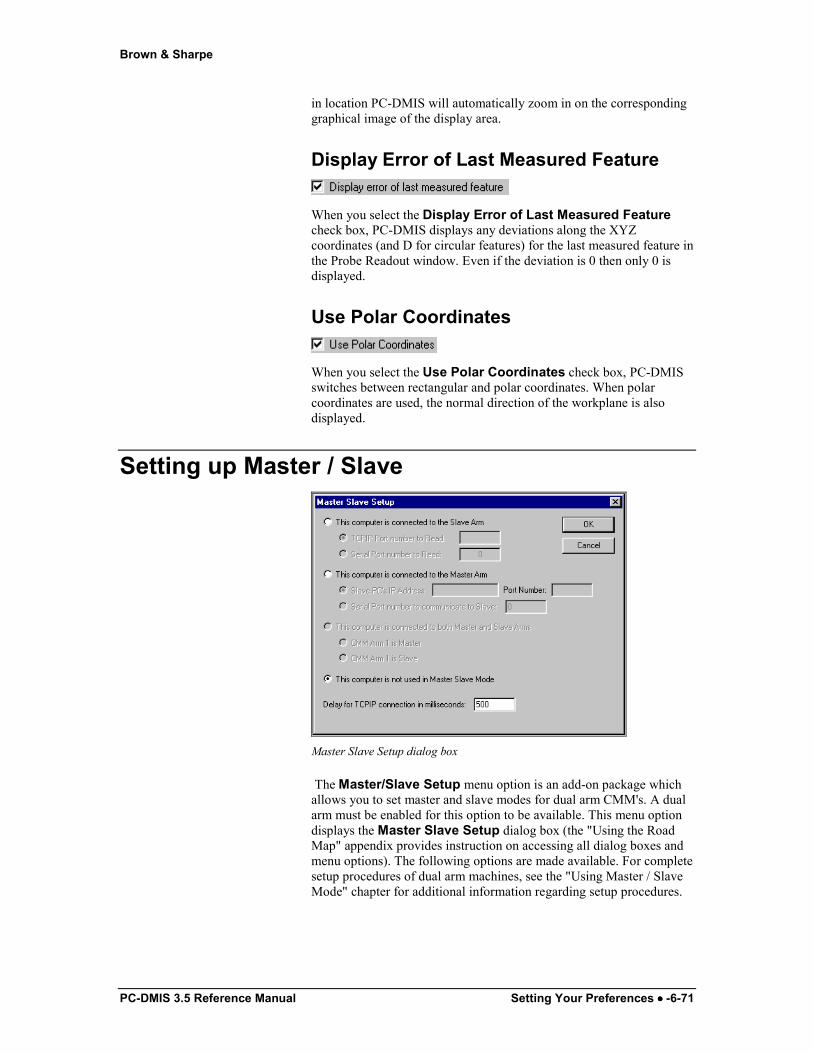
Brown & Sharpe
PC-DMIS 3.5 Reference Manual Setting Your Preferences •••• -6-71
in location PC-DMIS will automatically zoom in on the corresponding graphical image of the display area.
Display Error of Last Measured Feature
When you select the Display Error of Last Measured Feature check box, PC-DMIS displays any deviations along the XYZ coordinates (and D for circular features) for the last measured feature in the Probe Readout window. Even if the deviation is 0 then only 0 is displayed.
Use Polar Coordinates
When you select the Use Polar Coordinates check box, PC-DMIS switches between rectangular and polar coordinates. When polar coordinates are used, the normal direction of the workplane is also displayed.
Setting up Master / Slave
Master Slave Setup dialog box
The Master/Slave Setup menu option is an add-on package which allows you to set master and slave modes for dual arm CMM's. A dual arm must be enabled for this option to be available. This menu option displays the Master Slave Setup dialog box (the "Using the Road Map" appendix provides instruction on accessing all dialog boxes and menu options). The following options are made available. For complete setup procedures of dual arm machines, see the "Using Master / Slave Mode" chapter for additional information regarding setup procedures.
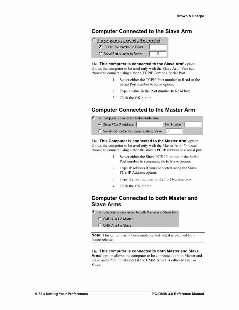
Brown & Sharpe
6-72 •••• Setting Your Preferences PC-DMIS 3.5 Reference Manual
Computer Connected to the Slave Arm
The 'This computer is connected to the Slave Arm' option allows the computer to be used only with the Slave Arm. You can choose to connect using either a TCPIP Port or a Serial Port.
1. Select either the TCPIP Port number to Read or the Serial Port number to Read option.
2. Type a value in the Port number to Read box.
3. Click the OK button.
Computer Connected to the Master Arm
The 'This Computer is connected to the Master Arm' option allows the computer to be used only with the Master Arm. You can choose to connect using either the slave's PC IP address or a serial port.
1. Select either the Slave PC'S IP option or the Serial Port number to communicate to Slave option.
2. Type IP address if you connected using the Slave PC's IP Address option.
3. Type the port number in the Port Number box.
4. Click the OK button.
Computer Connected to both Master and Slave Arms
Note: This option hasn't been implemented yet; it is planned for a future release.
The 'This computer is connected to both Master and Slave Arms' option allows the computer to be connected to both Master and Slave arms. You must select if the CMM Arm 1 is either Master or Slave.
Brown & Sharpe
PC-DMIS 3.5 Reference Manual Setting Your Preferences •••• -6-73
Computer is not used in Master Slave Mode
If the computer is not used in a Master/Slave mode relationship, select the 'This computer is not used in Master Slave Mode' option.
Delay for TCPIP Connection
The Delay for TCPIP connection in milliseconds box allows you to type the number of milliseconds that PC-DMIS will delay before attempting a TCPIP connection with the Master or Slave arm setup for use with the current computer.
Defining the Rotary Table Selecting the Rotary Table Setup menu option displays the Rotary Table Setup dialog box (the "Using the Road Map" appendix provides instruction on accessing all dialog boxes and menu options). This dialog box allows you to define the rotary table. You can only accept one option per category.
1. Select the type of table being used. If a Dual Rotary Table is set up, indicate if Table 1 or 2 is active. Selecting Dual Rotary Tables also displays the Active Rotary Table toolbar once you click the OK button. This toolbar contains two icons that allow you to select which rotary table is active. Note on Index Type Rotary Tables: Index type rotary tables have a finite number of specific angles to which they can be positioned. Generally, they have a fixed increment (in degrees of rotation) from a given position to the next available position. The incremental amount will vary, based on your specific table. Please consult your Rotary table documentation if necessary. Infinite type rotary tables will accept any position (in degrees).
2. Determine if the rotary table is Manual or DCC and select the appropriate option.
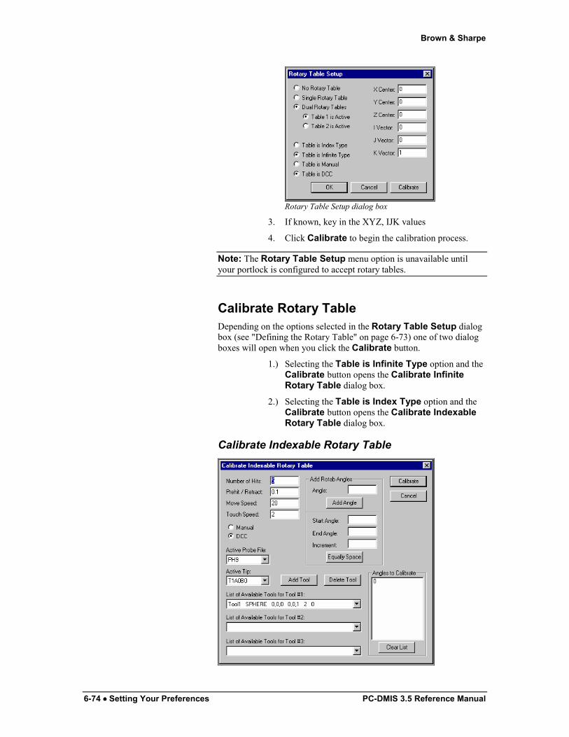
Brown & Sharpe
6-74 •••• Setting Your Preferences PC-DMIS 3.5 Reference Manual
Rotary Table Setup dialog box
3. If known, key in the XYZ, IJK values
4. Click Calibrate to begin the calibration process.
Note: The Rotary Table Setup menu option is unavailable until your portlock is configured to accept rotary tables.
Calibrate Rotary Table Depending on the options selected in the Rotary Table Setup dialog box (see "Defining the Rotary Table" on page 6-73) one of two dialog boxes will open when you click the Calibrate button.
1.) Selecting the Table is Infinite Type option and the Calibrate button opens the Calibrate Infinite Rotary Table dialog box.
2.) Selecting the Table is Index Type option and the Calibrate button opens the Calibrate Indexable Rotary Table dialog box.
Calibrate Indexable Rotary Table

Brown & Sharpe
PC-DMIS 3.5 Reference Manual Setting Your Preferences •••• -6-75
Calibrate Indexable Rotary Table
Using the Calibrate Indexable Rotary Table dialog box you can select the options that will be used to calibrate the selected table. Once the options within the dialog box are satisfactory, click the Calibrate button to start the rotary table calibration process.
Usage Note: The indexable rotary table calibration must include the 0 position. Additionally, all the angles that will actually be used in a part program must also be calibrated. This calibration procedure calculates and stores a transformation for all other angles relative to 0 position.
Calibration Note: The indexable rotary table calibration procedure requires a valid XYZ, IJK for the table in order to run properly. This can be accomplished in two ways. 1.) If the values are known, they can be manually typed into the Rotary Table Setup dialog box. This will usually not be the case. 2) Initially select the Table is Infinite Type option and complete an infinite rotary table calibration, which will calculate and save the XYZ, IJK. Then select the Table is Indexable Type and perform the indexable rotary table calibration. This is normally only an issue during the initial software installation/setup or if the rotary table has been moved or if something has happened to significantly alter the origin of the machine coordinate system. Once the XYZ, IJK is determined closely enough that the indexable rotary table calibration procedure can run successfully it is not necessary to go back and re-run the infinite rotary table calibration in order to re-run the indexable rotary table calibration.
Add Rotab Angles The Add Rotab Angles area allows you to define the list of table angles that will be included in the calibration. You can define one angle at a time, or you can define an incremented range of angles. Defined angles are then placed in the Angles to Calibrate list. When you click Calibrate PC-DMIS will then calibrate the rotary table using the defined angles.
Example: If you want to calibrate all the angles between 5 and 95 degrees with a 10 degree increment between each angle, you would fill in the Start Angle, End Angle, and Increment boxes with 5, 95, and 10 respectively, and then click the Equally Space button.
Angles to Calibrate list This list contains all the table angles for the calibration. You can add angles to this list from the Add Rotab Angles area. The Angles to Calibrate list must use the zero angle.
Other Dialog box Parameters This dialog box also contains many of the same options described in the "Defining Hardware" chapter.

Brown & Sharpe
6-76 •••• Setting Your Preferences PC-DMIS 3.5 Reference Manual
• For information on Number of Hits, Prehit / Retract, Move Speed, Touch Speed, Manual / DCC, List of Available Tools, Add Tool, and Delete Tool, see the “Measure” topic in the “Defining Hardware” chapter.
• For information on Active Probe File and Active Tip, see the “Defining Probes” topic in the “Defining Hardware” chapter.
Calibrate Infinite Rotary Table
Calibrate Infinite Rotary Table dialog box
The Calibrate Infinite Rotary Table dialog box differs from the Calibrate Indexable Rotary Table dialog box in these areas:
• Instead of the Angles to Calibrate list, the dialog displays the Table Angles list.
• You don’t have to use the 0.0 angle in the Table Angles list.
• Instead of three calibration tools, the dialog box only displays one calibration tool.
See “Calibrate Indexable Rotary Table” on page 6-74 above for information on the specific options contained in this dialog box.
Setting Up Probe Changer Options Selecting the Probe Changer menu option displays the Probe Changer dialog box (the "Using the Road Map" appendix provides instruction on accessing all dialog boxes and menu options). This dialog box allows you to setup various options that can be used on a probe changer. These tabs are available on the dialog box:
Type This allows you to select the probe changer type.
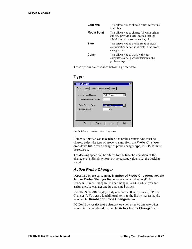
Brown & Sharpe
PC-DMIS 3.5 Reference Manual Setting Your Preferences •••• -6-77
Calibrate This allows you to choose which active tips to calibrate.
Mount Point This allows you to change AB wrist values and also provide a safe location that the CMM can move to after each cycle.
Slots This allows you to define probe or stylus configuration for existing slots in the probe changer rack.
Comm This allows you to work with your computer's serial port connection to the probe changer.
These options are described below in greater detail.
Type
Probe Changer dialog box—Type tab
Before calibration can take place, the probe changer type must be chosen. Select the type of probe changer from the Probe Changer drop-down list. After a change of probe changer type, PC-DMIS must be restarted.
The docking speed can be altered to fine tune the operation of the change cycle. Simply type a new percentage value to set the docking speed.
Active Probe Changer Depending on the value in the Number of Probe Changers box, the Active Probe Changer list contains numbered items (Probe Changer1, Probe Changer2, Probe Changer3 etc.) to which you can assign a probe changer and its associated values.
Initially PC-DMIS displays only one item in this list, usually "Probe Changer1". You can add additional items to the list by increasing the value in the Number of Probe Changers box.
PC-DMIS stores the probe changer type you selected and any other values for the numbered item in the Active Probe Changer list.
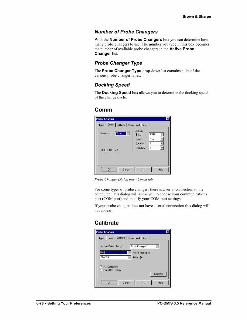
Brown & Sharpe
6-78 •••• Setting Your Preferences PC-DMIS 3.5 Reference Manual
Number of Probe Changers With the Number of Probe Changers box you can determine how many probe changers to use. The number you type in this box becomes the number of available probe changers in the Active Probe Changer list.
Probe Changer Type The Probe Changer Type drop-down list contains a list of the various probe changer types.
Docking Speed The Docking Speed box allows you to determine the docking speed of the change cycle.
Comm
Probe Changer Dialog box—Comm tab
For some types of probe changers there is a serial connection to the computer. This dialog will allow you to choose your communications port (COM port) and modify your COM port settings.
If your probe changer does not have a serial connection this dialog will not appear.
Calibrate
Brown & Sharpe
PC-DMIS 3.5 Reference Manual Setting Your Preferences •••• -6-79
Probe Changer dialog box—Calibrate tab
Before probe configurations can be loaded into the rack, consider the following:
• The probe or stylus must be chosen from the Type tab and calibrated.
• The rack should be squared to one of the CMM's axes.
• The PS35R stylus that was supplied by Renishaw must be used to calibrate the probe changer.
• Verify that the stylus has been calibrated before starting this process. (See "Defining Probes" in the "Defining Hardware" chapter.
CAUTION: The optoelectronic infrared detection system is always active. If it is accidentally tripped, the PI200 (probe controller) will deactivate the TP200.
Active Probe Changer From the Active Probe Changer list you can select what probe changer to calibrate.
See "Active Probe Changer" under the Type tab on page 6-77 for information on this list.
Active Probe File The Active Probe File drop-down list allows you to select a probe to use for the calibration process.
Active Tip The Active Tip drop-down list allows you to choose a tip configuration for the probe selected.
Full Calibration If you select the Full Calibration option, PC-DMIS will measure the entire probe changer. This is the most often used method of calibration and for some the only method available. It is recommended that the operator use the full calibration method.
Partial Calibration The Partial Calibration option will only calibrate a portion of the probe changer. For the ACR1 it will only measure the datum sphere on the probe changer.
Single Port Calibration Some probe changers will allow you to measure only a single slot after a successful full calibration.
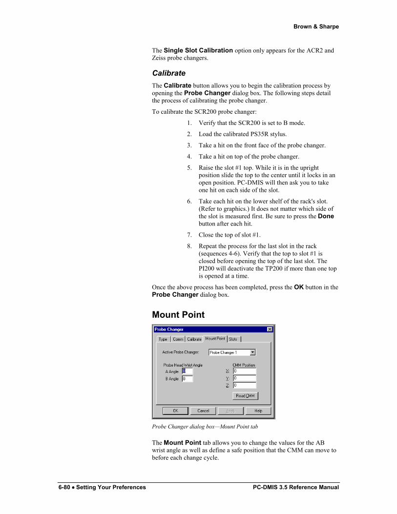
Brown & Sharpe
6-80 •••• Setting Your Preferences PC-DMIS 3.5 Reference Manual
The Single Slot Calibration option only appears for the ACR2 and Zeiss probe changers.
Calibrate The Calibrate button allows you to begin the calibration process by opening the Probe Changer dialog box. The following steps detail the process of calibrating the probe changer.
To calibrate the SCR200 probe changer:
1. Verify that the SCR200 is set to B mode.
2. Load the calibrated PS35R stylus.
3. Take a hit on the front face of the probe changer.
4. Take a hit on top of the probe changer.
5. Raise the slot #1 top. While it is in the upright position slide the top to the center until it locks in an open position. PC-DMIS will then ask you to take one hit on each side of the slot.
6. Take each hit on the lower shelf of the rack's slot. (Refer to graphics.) It does not matter which side of the slot is measured first. Be sure to press the Done button after each hit.
7. Close the top of slot #1.
8. Repeat the process for the last slot in the rack (sequences 4-6). Verify that the top to slot #1 is closed before opening the top of the last slot. The PI200 will deactivate the TP200 if more than one top is opened at a time.
Once the above process has been completed, press the OK button in the Probe Changer dialog box.
Mount Point
Probe Changer dialog box—Mount Point tab
The Mount Point tab allows you to change the values for the AB wrist angle as well as define a safe position that the CMM can move to before each change cycle.
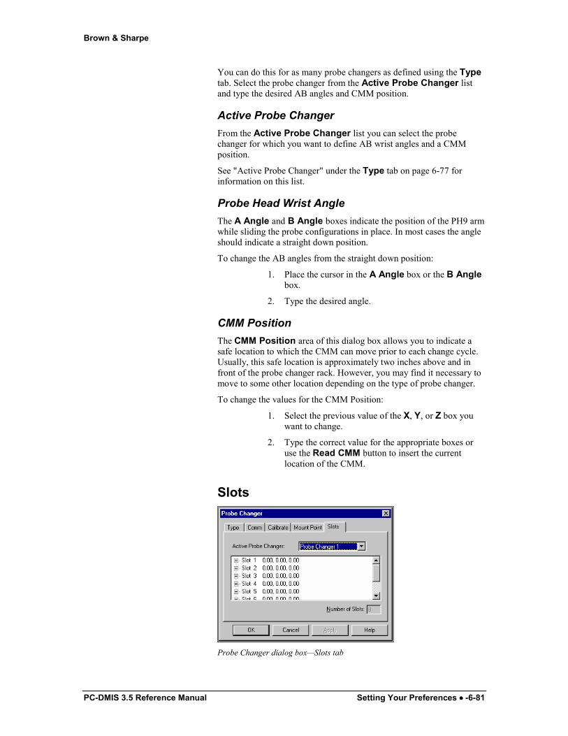
Brown & Sharpe
PC-DMIS 3.5 Reference Manual Setting Your Preferences •••• -6-81
You can do this for as many probe changers as defined using the Type tab. Select the probe changer from the Active Probe Changer list and type the desired AB angles and CMM position.
Active Probe Changer From the Active Probe Changer list you can select the probe changer for which you want to define AB wrist angles and a CMM position.
See "Active Probe Changer" under the Type tab on page 6-77 for information on this list.
Probe Head Wrist Angle The A Angle and B Angle boxes indicate the position of the PH9 arm while sliding the probe configurations in place. In most cases the angle should indicate a straight down position.
To change the AB angles from the straight down position:
1. Place the cursor in the A Angle box or the B Angle box.
2. Type the desired angle.
CMM Position The CMM Position area of this dialog box allows you to indicate a safe location to which the CMM can move prior to each change cycle. Usually, this safe location is approximately two inches above and in front of the probe changer rack. However, you may find it necessary to move to some other location depending on the type of probe changer.
To change the values for the CMM Position:
1. Select the previous value of the X, Y, or Z box you want to change.
2. Type the correct value for the appropriate boxes or use the Read CMM button to insert the current location of the CMM.
Slots
Probe Changer dialog box—Slots tab
Brown & Sharpe
6-82 •••• Setting Your Preferences PC-DMIS 3.5 Reference Manual
The probe changer is a rack that provides slots for different probe configurations. The Slots tab allows you to define the probe configuration for each slot that will be used. The default for each slot is "no probe". You can define the probe configuration for each slot of the selected probe changer.
To Define the Probe Configuration for Each Slot 1. Select the appropriate probe changer from the Active
Probe Changer list.
2. Click the plus sign (+) to the left of the slot number. You'll notice that PC-DMIS displays a "no probe" item as the default.
3. Double click or right click on the "no probe" item. A list will appear.
4. Assign the appropriate probe file to each slot. Each probe configuration must be loaded into the rack using the CMM Arm and Load Active Probe option. (Do not insert the probe into the rack by hand.)
To Change a Defined Probe Back to the "no probe" Default
1. Select the appropriate probe changer from the Active Probe Changer list.
2. Double click on the slot to change. A list appears.
3. Select "no probe" from the available list.
To Add or Remove Slots from the Dialog Box With some types of probe changers you can define the number of slots.
1. Select the appropriate probe changer from the Active Probe Changer list.
2. Change the value in the Number of Slots box.
3. Click the Apply button to immediately see the changes.
If your probe changer does not allow for a changing amount of slots then the Number of Slots box will be disabled.
Loading the Active Probe The Load Active Probe menu option loads the active probe required by the part program. While in Learn mode, use the Probe Utility dialog box to change the loaded probe file(s). The Probe Changer Setup dialog box allows you to define the appropriate probe configurations for each slot that will be used. The Load Active Probe option can then be used to tell the machine to exchange the necessary probe configuration(s) (the "Using the Road Map" appendix provides instruction on accessing all dialog boxes and menu options).
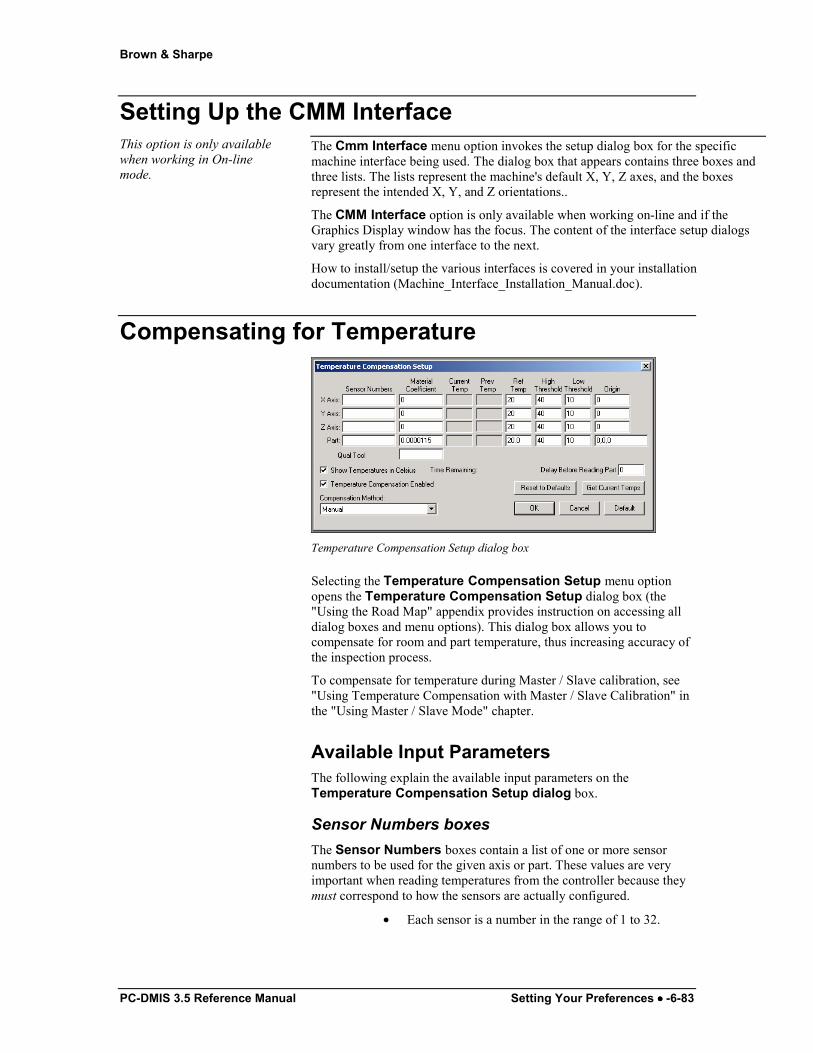
Brown & Sharpe
PC-DMIS 3.5 Reference Manual Setting Your Preferences •••• -6-83
Setting Up the CMM Interface This option is only available when working in On-line mode.
The Cmm Interface menu option invokes the setup dialog box for the specific machine interface being used. The dialog box that appears contains three boxes and three lists. The lists represent the machine's default X, Y, Z axes, and the boxes represent the intended X, Y, and Z orientations..
The CMM Interface option is only available when working on-line and if the Graphics Display window has the focus. The content of the interface setup dialogs vary greatly from one interface to the next.
How to install/setup the various interfaces is covered in your installation documentation (Machine_Interface_Installation_Manual.doc).
Compensating for Temperature
Temperature Compensation Setup dialog box
Selecting the Temperature Compensation Setup menu option opens the Temperature Compensation Setup dialog box (the "Using the Road Map" appendix provides instruction on accessing all dialog boxes and menu options). This dialog box allows you to compensate for room and part temperature, thus increasing accuracy of the inspection process.
To compensate for temperature during Master / Slave calibration, see "Using Temperature Compensation with Master / Slave Calibration" in the "Using Master / Slave Mode" chapter.
Available Input Parameters The following explain the available input parameters on the Temperature Compensation Setup dialog box.
Sensor Numbers boxes The Sensor Numbers boxes contain a list of one or more sensor numbers to be used for the given axis or part. These values are very important when reading temperatures from the controller because they must correspond to how the sensors are actually configured.
• Each sensor is a number in the range of 1 to 32.

Brown & Sharpe
6-84 •••• Setting Your Preferences PC-DMIS 3.5 Reference Manual
• Items in the list can be either a single number or a range from first to last.
• Items are separated by either commas or left blank.
• The input allows up to 32 values for any axis or the part.
For “manual” mode these numbers are relatively meaningless but at least one sensor number must be assigned for each axis and the part.
Material Coefficient boxes The Material Coefficient boxes contain numbers reflecting the material property, and are the fractional change in length per unit change in temperature.
• Values vary depending on what type of material was used to make the scales on the machine axes and on what the part is made of.
• Units are per degree C or per degree F, depending on the selection of the checkbox for displaying in Celsius or not.
• This can be thought of as meters/meter/degree C or inches/inch/degree F but since the length in both the numerator and denominator are in the same units they divide out.
Example: A scale with a coefficient of 11.5 microns/meter/degree C becomes 0.0000115 meters/meter/degree C or just 0.0000115/degree C.
Qual Tool This box allows you to specify the material coefficient for the probe qualification tool separately from the part.
Current Temp boxes The Current Temp boxes contain the current temperatures in the appropriate units. You can either type these or read them in from the controller depending on the type of machine available and the selected options.
Prev Temp boxes The Previous Temp boxes always contain the previously read temperatures. If no temperatures were previously read in, these values are either zero or left blank.
Ref Temp boxes The Ref Temp boxes contain the reference temperature from which temperature compensation adjustments need to be applied.
• The amount of correction to be applied is based on multiplying the material coefficient by the difference between the current and reference temperatures.
Brown & Sharpe
PC-DMIS 3.5 Reference Manual Setting Your Preferences •••• -6-85
Amount of Correction = Material Coefficient x (Current Temp – Reference Temp)
• If the current temperature is the same as the reference temperature the net effect is that no thermal compensation adjustment is applied.
• The value in these boxes is almost always 20 degrees C, or the Fahrenheit equivalent.
High Threshld boxes The High Threshld boxes contain an upper limit (in the appropriate units) on the current temperature above which no further thermal compensation will be applied. PC-DMIS doesn’t produce any warning or error message.
Example: With a reference temp of 20 degrees C, a current temp of 35 degrees C and a high threshold of 30 degrees C the amount of correction actually applied would be based on a difference of (30 – 20) instead of (35 – 20) because the current temperature exceeded the upper limit.
Low Threshld boxes The Low Threshld boxes is conceptually like the high threshold except it provides a lower limit on the current temperature below which no further thermal compensation will be applied.
Origin boxes The Origin boxes are used to determine the length of the item to which thermal compensation is being applied.
Length = Current Position Value – Origin Value
• The X, Y, and Z values of the Origin boxes will be zero most of the time. However, some types of machines do not use zero for the origin of their scales.
• The Part value will typically also be zero unless there is some special type of fixturing constraint.
Show Temperatures in Celsius The Show Temperatures in Celsius check box affects both the temperatures and the material coefficient.
• If you select this check box, the display will use degrees Celsius.
• If you clear this check box, PC-DMIS will use degrees Fahrenheit.
Temperature Compensation Enabled The Temperature Compensation Enabled check box tells PC-DMIS to use temperature compensation.

Brown & Sharpe
6-86 •••• Setting Your Preferences PC-DMIS 3.5 Reference Manual
• If not selected, PC-DMIS does not perform any temperature compensation, and the TEMPCOMP command (if present in the part program) will have no effect.
• If selected, PC-DMIS behaves according to the input parameters.
Compensation Method The following are the available compensation methods and their respective processes in PC-DMIS.
Method Process Manual Compensation is manual (controlled by
your input) with no involvement from the machine controller.
PC-DMIS performs all compensation calculations.
During part program execution the Temperature Compensation Setup dialog box opens and you can edit the current settings before proceeding with the rest of the program.
Read Temperatures from Controller
When using a machine that supports this option, PC-DMIS reads the current temperatures from the controller automatically rather than you supplying the data.
PC-DMIS performs all compensation calculations. The controller only provides the current temperatures.
During part program execution the Temperature Compensation Setup dialog box does not open.
The part program does not pause for your confirmation.
Controller Compensates Axes Only
The controller performs compensation of the machine axes itself.
The inputs for the axes will not be used. Part input parameters apply since PC-
DMIS still performs compensation for the part.
During part program execution the Temperature Compensation Setup dialog box does not open.
The program does not pause for your confirmation.
Controller Comps Axes and Part
The controller performs compensation of both the machine axes and the part.
The inputs for the axes are not used. PC-DMIS does not perform any
compensation calculations. The input for the part for the material
coefficient, reference temperature and origin must still be supplied because PC-

Brown & Sharpe
PC-DMIS 3.5 Reference Manual Setting Your Preferences •••• -6-87
DMIS must pass that information down to the controller.
During part program execution the Temperature Compensation Setup dialog box does not open.
The program does not pause for your confirmation.
Time Remaining The Time Remaining display shows the time remaining before the temperature reading takes place. This only displays if you set up a delay period for execution. See “Delay Before Reading Part” on page 6-87 below.
Delay Before Reading Part The Delay Before Reading Part box allows you to specify a period that PC-DMIS will wait during part program execution before reading the Sensors to obtain the current temperatures. If zero is entered then there is no pause.
Reset to Defaults The Resets to Defaults button updates any previously modified values with the previously saved values. If this is on a DEA machine and a serv1.stp is available then PC-DMIS will read that file.
Get Current Temps If you select the Read Temps from Controller method from the Compensation Method list, and if you use a machine that supports this option, the Get Current Temps button causes PC-DMIS to read the current temperatures from the controller and display them in the Temperature Compensation Setup dialog box.
TEMP COMP Command in the Edit Window When you accept the inputs in the Temperature Compensation Setup dialog box by clicking the OK button PC-DMIS inserts a TEMPCOMP command into the part program, as shown below.
Example of Inserted TEMPCOMP command
Normally a part program will only use one TEMPCOMP command The TEMPCOMP command should be placed near the top of the program prior to any measurements. When you execute the part program, it behaves according to the various input parameters.

Brown & Sharpe
6-88 •••• Setting Your Preferences PC-DMIS 3.5 Reference Manual
Controller Support Not all comp methods are supported by all controllers. The following are the supported controllers for the different compensation methods. See “Compensation Method” on page 6-86. Compensation Methods Supported Controllers Manual All, there is no controller involvement
with this method
Read Temps from Controller DEA (only with DEAC family controllers), Sharpe32z using Leitz protocol
Controller Comps Axes Only Sharpe32z using Leitz protocol
Controller Comps Axes and Part Sharpe32z using Leitz protocol
Specifying External Directories to Search
Search Path dialog box
The Set Search Path menu option allows you to specify which external file PC-DMIS uses for these commands:
• Loadprobe
• Recall Alignment
• Call Subroutine
To modify the directory being searched:
1. Access the Search Path dialog box (the "Using the Road Map" appendix provides instruction on accessing all dialog boxes and menu options).
2. Choose LOADPROBE, RECALL, or SUBROUTINE from the Search For drop-down list.
3. Select or clear the Search Current Directory check box.
4. Select or clear the Search Specified Directory check box.
5. Type the directory pathway in the box (or use the Browse button to select a directory).
6. Click the Ok button. The changes will be made and the dialog box will close.

Brown & Sharpe
PC-DMIS 3.5 Reference Manual Setting Your Preferences •••• -6-89
Clicking the Apply button will allow you to save the changes you make, but the Search Path dialog box will remain open.
The Search Path dialog box contains the following options:
Search For
The Search for drop-down list lets you select one of these three options:
1) LOADPROBE
2) RECALL
3) SUBROUTINE
For each of these you can then set up a directory that PC-DMIS will search in when the command for the selected option is encountered in the Edit window.
Search Current Directory
The Search Current Directory check box enables or disables searching within the current directory.
Search Current Directory First
When selected, (and if both the Search Current Directory and the Search Specified Directory check boxes are selected) this check box allows you search in both the current directory and the user specified directory. The order of the search depends on if this check box is selected:
• If selected PC-DMIS will first access the current directory and then the user specified directory.
• If cleared, the search order will be reversed, accessing first the user specified directory and then the current directory.
Search Specified Directory
The Search Specified Directory check box enables or disables searching in a directory you specify. The pathway for the directory you specify will be entered in the box just below the check box.

Brown & Sharpe
6-90 •••• Setting Your Preferences PC-DMIS 3.5 Reference Manual
Browse Button
The Browse button allows you to browse for a user specified directory. When clicked, your system's directory structure will appear:
Example of one system's directory structure inside the Choose Directory dialog box.
The directory window contains the folders and levels of folders available to you. Simply, highlight the directory you want PC-DMIS to search in and click the OK button. PC-DMIS returns you to the Search Path dialog box. Notice that the directory pathway now appears in the Search Specified Directory box.
Note: The directory structure in the Choose Directory dialog box varies from computer to computer. The above is only an example of what you may encounter.
Changing OpenGL Options
OpenGL Options dialog box
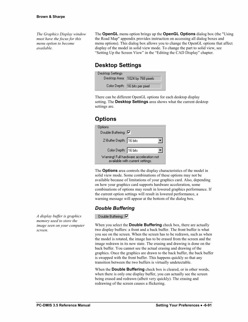
Brown & Sharpe
PC-DMIS 3.5 Reference Manual Setting Your Preferences •••• -6-91
The Graphics Display window must have the focus for this menu option to become available.
The OpenGL menu option brings up the OpenGL Options dialog box (the "Using the Road Map" appendix provides instruction on accessing all dialog boxes and menu options). This dialog box allows you to change the OpenGL options that affect display of the model in solid view mode. To change the part to solid view, see “Setting Up the Screen View” in the “Editing the CAD Display” chapter.
Desktop Settings
There can be different OpenGL options for each desktop display setting. The Desktop Settings area shows what the current desktop settings are.
Options
The Options area controls the display characteristics of the model in solid view mode. Some combinations of these options may not be available because of limitations of your graphics card. Also, depending on how your graphics card supports hardware acceleration, some combinations of options may result in lowered graphics performance. If the current option settings will result in lowered performance, a warning message will appear at the bottom of the dialog box.
Double Buffering A display buffer is graphics memory used to store the image seen on your computer screen.
When you select the Double Buffering check box, there are actually two display buffers: a front and a back buffer. The front buffer is what you see on the screen. When the screen has to be redrawn, such as when the model is rotated, the image has to be erased from the screen and the image redrawn in its new state. The erasing and drawing is done on the back buffer. You cannot see the actual erasing and drawing of the graphics. Once the graphics are drawn to the back buffer, the back buffer is swapped with the front buffer. This happens quickly so that any transition between the two buffers is virtually undetectable.
When the Double Buffering check box is cleared, or in other words, when there is only one display buffer, you can actually see the screen being erased and redrawn (albeit very quickly). The erasing and redrawing of the screen causes a flickering.

Brown & Sharpe
6-92 •••• Setting Your Preferences PC-DMIS 3.5 Reference Manual
In summary, double buffering produces a more visually pleasing graphical display than single buffering.
Z-Buffer Depth
The Z-Buffer Depth list controls how much graphics memory is used for the z-buffer. The z-buffer determines which parts of a 3D model lie in front of other parts of the model. If you use insufficient bits for the z-buffer, visual artifacts may appear on the model in solid view mode. These artifacts are areas on the model that are drawn in front of other parts of the model when they should actually be hidden. These artifacts do not affect the accuracy of PC-DMIS but are simply inaccuracies in the visual display of the model.
Color Depth
The Color Depth list controls how much graphics memory your system uses for the color information of each pixel. This number is usually dependent on the color depth of the Desktop Settings.
Tessellation
The tessellation value is the default value used to break up surfaces into patches for shading.
The Tessellation area controls the drawn image by setting a tessellation multiplier in the Multiplier Value box. PC-DMIS multiplies the Multiplier Value by the tessellation value for the given CAD system. These values are then used in the generation of the shaded image.


![Contents · 2017. 6. 9. · Lync 2011 Mac Reference Guide [client version 14.0.2] Contents Signing In! 2 Quick Overview! 3 Setting Display Options! 4 Setting Lync Preferences! 5 Voice](https://static.fdocuments.in/doc/165x107/6032bac4dcc3f231d47b40e6/contents-2017-6-9-lync-2011-mac-reference-guide-client-version-1402-contents.jpg)


