Chapter Six: Digital Circuits By: Mrs. Hiwot Tegegn (lecturer)
22
Jimma University College of Natural Sciences Department of Physics April 2020 Lecture Notes : Electronics I (Phys 2062) By: Mrs. Hiwot Tegegn (lecturer) Chapter Six: Digital Circuits
Transcript of Chapter Six: Digital Circuits By: Mrs. Hiwot Tegegn (lecturer)

Jimma University College of Natural Sciences Department of Physics
April 2020
Lecture Notes : Electronics I (Phys 2062)
By: Mrs. Hiwot Tegegn (lecturer)
Chapter Six: Digital Circuits

Outline of the Chapter
The junction field effect transistor (JFET), JFET Common Source Amplifier, JFET
Common Drain amplifier
Insulated-Gate Field Effect Transistor. Power,
Multiple Transistor Circuit

Chapter Six: Digital Circuits In analog electronics, voltage is a continuous variable. This is useful because most physical quantities we encounter are continuous: sound levels, light intensity, temperature, pressure, etc. Digital electronics, in contrast, is characterized by only two distinguishable voltages. These
two states are called by various names: on/off, true/false, high/low, and 1/0 In practice, these two states are defined by the circuit voltage being above or below a
certain value By converting continuous analog signals into a nite number of discrete states, a process called digitization, This is the primary advantage of digital electronics: it is relatively immune to the noise that
is ubiquitous in electronic circuits Although digital circuits have excellent noise immunity, they also are limited to producing
only two levels. This does not appear to be very helpful in representing the continuous signals we so frequently encounter.
The explosion in digital techniques and technology has been made possible by the incre- ible increase in the density of digital circuitry, its robust performance, its relatively low cost,
and its speed. The requirement of using many bits in reproduction is no longer an issue: This circuitry is based upon the transistor, which can be operated as a switch with two
states. Hence, the digital information is intrinsically binary. So in practice, the terms digital and binary are used interchangeably. In the following sections we summarize some conventions for defining the binary states and for doing binary arithmetic.

Application of logic circuit
Binary Logic States
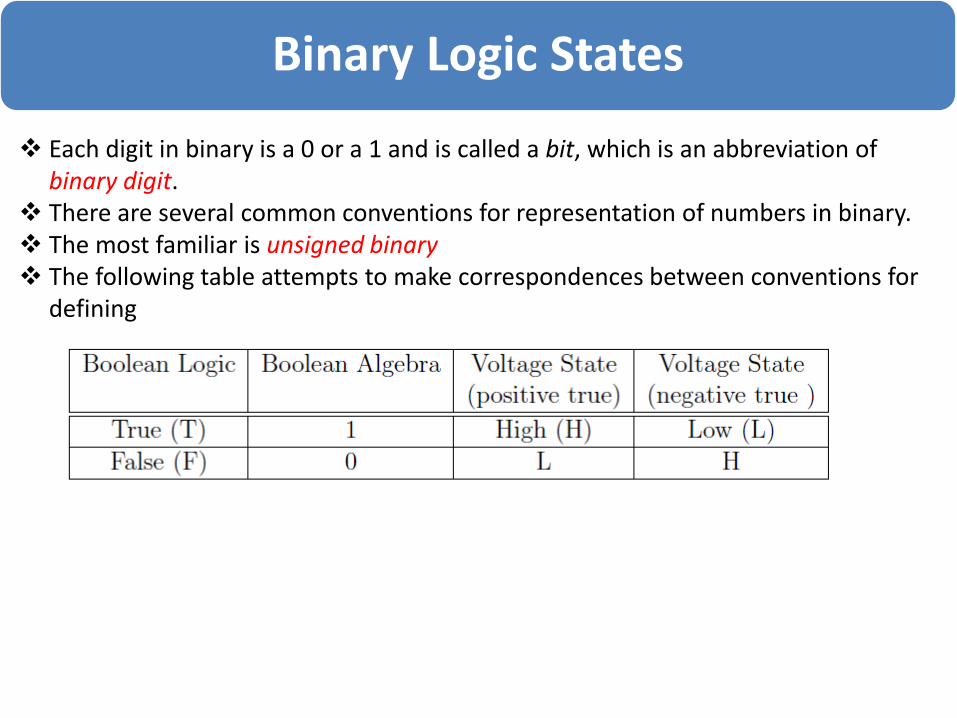
Each digit in binary is a 0 or a 1 and is called a bit, which is an abbreviation of binary digit.
There are several common conventions for representation of numbers in binary. The most familiar is unsigned binary The following table attempts to make correspondences between conventions for
defining binary logic states.

Numbers systems

Numbers systems
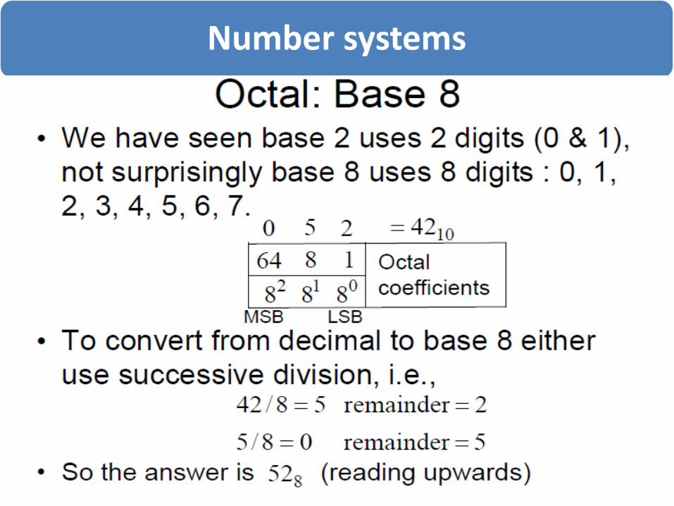
Number systems

Number systems

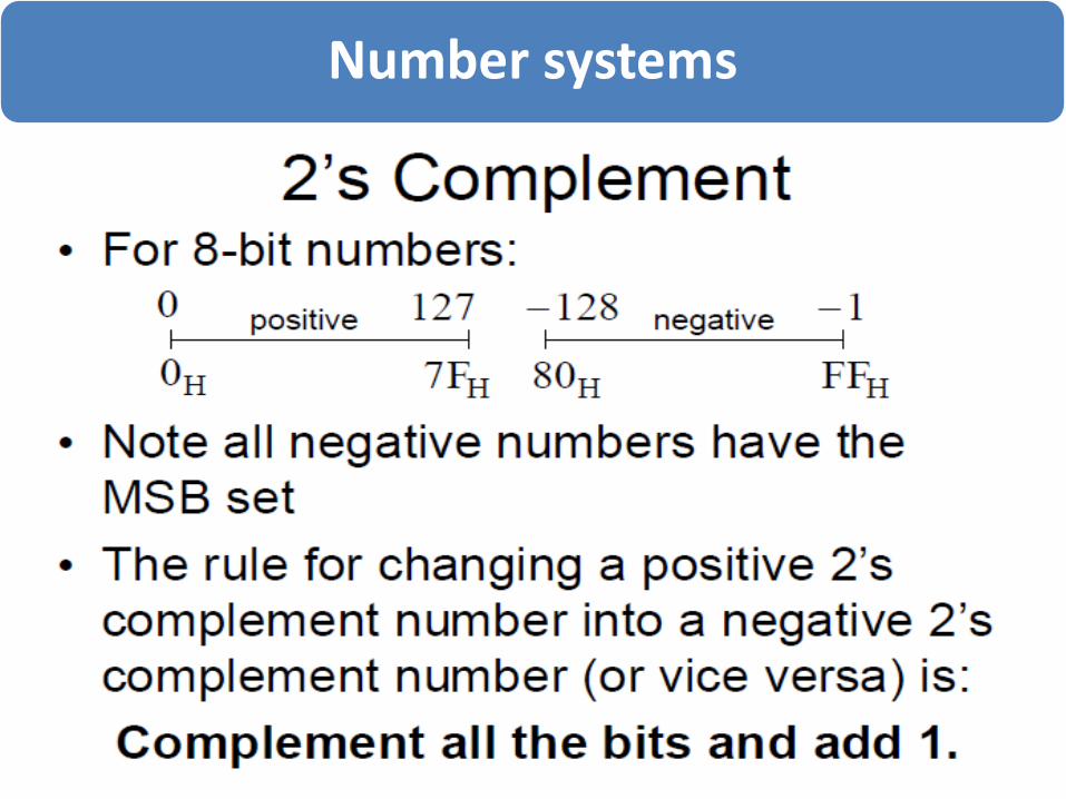
Number systems

Number systems

Number systems
Number systems

Logic Gates and Combinational Logic
Logic gates are the building blocks of digital circuits Basic logic circuits with one or more inputs and one output are
known as gates Gates are used as the building blocks in the design of more complex
digital logic circuits
Representing Logic Functions There are several ways of representing logic functions:
Symbols to represent the gates Truth tables Boolean algebra
The basic circuit element for manipulating digital signals is the logic gate

Logic Gates
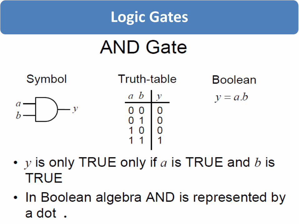
There are several types of logic gate, and each performs a particular logical operation on the input signals.
The logical operation of the gate is defined by its truth table which gives the output state for all possible combinations of the inputs
Logic Gates

Logic Gates

Logic Gates

Logic Gates

Logic Gates

Boolean Algebra
An algebra is a statement of rules for manipulating members of a set. There are rules for doing mathematical manipulations with
integers, real numbers, and complex numbers. There is also a special algebra for logical operations. It is
called Boolean algebra. They consist of definitions for the AND, OR, and NOT (or
inversion) operations, and several theorems Boolean algebra can be used to find alternative ways of
expressing a logical function