Chapter Seventeen BICYCLE AND PEDESTRIAN … Seventeen BICYCLE AND PEDESTRIAN ACCOMMODATIONS ......
89
BUREAU OF DESIGN AND ENVIRONMENT MANUAL Chapter Seventeen BICYCLE AND PEDESTRIAN ACCOMMODATIONS
Transcript of Chapter Seventeen BICYCLE AND PEDESTRIAN … Seventeen BICYCLE AND PEDESTRIAN ACCOMMODATIONS ......
BUREAU OF DESIGN AND ENVIRONMENT MANUAL
Chapter Seventeen
BICYCLE AND PEDESTRIAN ACCOMMODATIONS

Illinois BICYCLE AND PEDESTRIAN ACCOMMODATIONS February 2013
17-i HARD COPIES UNCONTROLLED
Chapter Seventeen BICYCLE AND PEDESTRIAN ACCOMMODATIONS
Table of Contents
Section Page 17-1 BICYCLE ACCOMMODATIONS: POLICIES AND PROCEDURES ...................... 17-1.1
17-1.01 Definitions .............................................................................................. 17-1.1 17-1.02 Policies .................................................................................................. 17-1.2
17-1.02(a) Exceptions to Consideration of Accommodations .......... 17-1.3 17-1.02(b) Partial Exceptions to Consideration
of Accommodations ....................................................... 17-1.3 17-1.03 Bikeway Warrants - Needs Assessment ............................................... 17-1.3 17-1.04 Determining Bicycle Travel Demand ..................................................... 17-1.6
17-1.04(a) Assessment of Bicycle Travel Within Highway Projects 17-1.8 17-1.04(b) Bicycle Travel Generators in Project Vicinity ................. 17-1.8 17-1.04(c) Public Coordination ........................................................ 17-1.8 17-1.04(d) Bicycle Travel Assessment ............................................ 17-1.8
17-1.05 Maintenance and Jurisdiction ................................................................ 17-1.8 17-1.06 Right-of-Way .......................................................................................... 17-1.9 17-1.07 Funding .................................................................................................. 17-1.9
17-2 DESIGN CRITERIA FOR BICYCLE FACILITIES.................................................... 17-2.1
17-2.01 Documentation ...................................................................................... 17-2.1 17-2.02 On-Road Accommodations ................................................................... 17-2.3
17-2.02(a) On-Road Bikeways on Rural Roadways ........................ 17-2.3 17-2.02(b) On-Road Bikeways On Shared Urban Roadways ......... 17-2.3 17-2.02(c) On-Road Marked Bicycle Lanes on Urban Roadways ... 17-2.5 17-2.02(d) Intersections ................................................................... 17-2.7 17-2.02(e) Bikeway on Highway Structures..................................... 17-2.11 17-2.02(f) Bikeway Adjacent to Highways ...................................... 17-2.17 17-2.02(g) Additional Considerations for Accommodations
on Existing Roadways .................................................... 17-2.17 17-2.02(h) Incidental Design Factors .............................................. 17-2.21 17-2.02(i) Bicycle Routes ............................................................... 17-2.23 17-2.02(j) Signing, Marking, and Traffic Control ............................. 17-2.23
17-2.03 Separated Bicycle Facilities ................................................................... 17-2.27
17-2.03(a) Shared-Use Paths .......................................................... 17-2.27 17-2.03(b) Width and Clearance ..................................................... 17-2.29 17-2.03(c) Design Speed ................................................................ 17-2.32
Illinois BICYCLE AND PEDESTRIAN ACCOMMODATIONS February 2013
17-ii HARD COPIES UNCONTROLLED
17-2.03(d) Horizontal Alignment and Superelevation ...................... 17-2.33 17-2.03(e) Drainage ........................................................................ 17-2.35 17-2.03(f) Grade ............................................................................. 17-2.37 17-2.03(g) Accessibility ................................................................... 17-2.38 17-2.03(h) Sight Distance ................................................................ 17-2.39 17-2.03(i) Bike Path Intersections .................................................. 17-2.40 17-2.03(j) Structures ....................................................................... 17-2.44 17-2.03(k) Signing and Marking ...................................................... 17-2.47 17-2.03(l) Lighting .......................................................................... 17-2.52 17-2.03(m) Restriction of Motor Vehicle Traffic ................................ 17-2.52 17-2.03(n) Pavement Structure ....................................................... 17-2.54
17-2.04 Accommodations Through a Roundabout ............................................. 17-2.58
17-2.04(a) Traversing Roundabouts like Motorized Vehicles .......... 17-2.58 17-2.04(b) Traversing Roundabouts like Pedestrians ..................... 17-2.59
17-3 BICYCLE OPERATING CHARACTERISTICS ........................................................ 17-3.1 17-4 PEDESTRIAN ACCOMMODATIONS ..................................................................... 17-4.1
17-4.01 General .................................................................................................. 17-4.1 17-4.02 Policies .................................................................................................. 17-4.1 17-4.03 Warrants ................................................................................................ 17-4.1 17-4.04 Design ................................................................................................... 17-4.2 17-4.05 Documentation ...................................................................................... 17-4.2 17-4.06 Pedestrian Accommodations During Construction ................................ 17-4.2 17-4.07 Maintenance and Jurisdiction ................................................................ 17-4.3
17-5 REFERENCES ........................................................................................................ 17-5.1 17-6 BICYCLE CHECKLISTS ......................................................................................... 17-6.1 17-7 PROPOSED RESOLUTION LANGUAGE FOR NON-PARTICIPATING LOCAL
AGENCIES .............................................................................................................. 17-7.1
Illinois BICYCLE AND PEDESTRIAN ACCOMMODATIONS March 2011
17-1.1 HARD COPIES UNCONTROLLED
Chapter Seventeen BICYCLE AND PEDESTRIAN
ACCOMMODATIONS
When planning transportation improvements, the Department considers the travel needs of all users of a transportation corridor including bicyclists and pedestrians. Bicycle and pedestrian travel demand in the vicinity of a project is determined early in the project planning phase. When sufficient demand is indicated, the Department will provide the appropriate accommodations.
The correct application of the criteria and guidelines presented in Chapter 17 will result in consistent designs and subtle roadway design changes that will facilitate bicycle and pedestrian travel. Such changes will provide improved transportation opportunities for both bicyclists and pedestrians.
17-1 BICYCLE ACCOMMODATIONS: POLICIES AND PROCEDURES
17-1.01 Definitions
The following terms and definitions apply to Chapter 17:
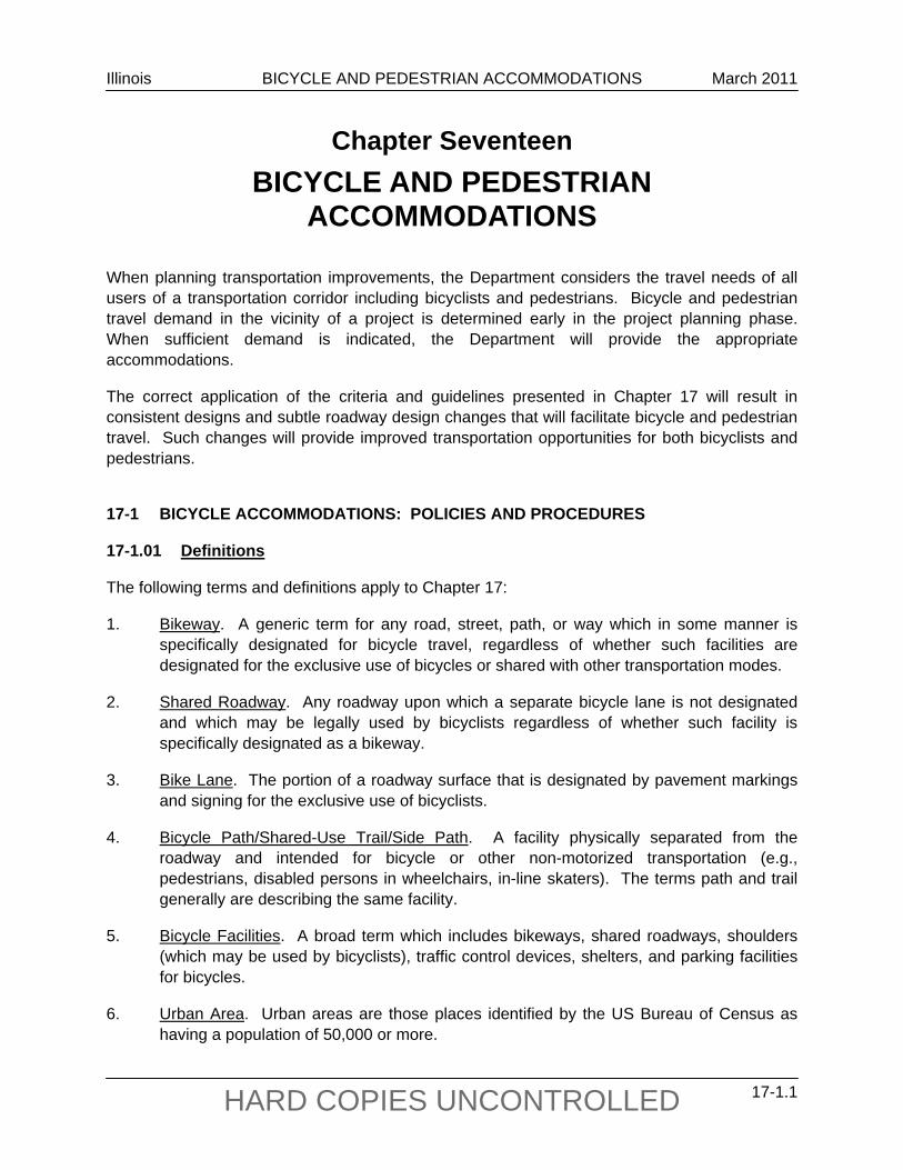
1. Bikeway. A generic term for any road, street, path, or way which in some manner is specifically designated for bicycle travel, regardless of whether such facilities are designated for the exclusive use of bicycles or shared with other transportation modes.
2. Shared Roadway. Any roadway upon which a separate bicycle lane is not designated and which may be legally used by bicyclists regardless of whether such facility is specifically designated as a bikeway.
3. Bike Lane. The portion of a roadway surface that is designated by pavement markings and signing for the exclusive use of bicyclists.
4. Bicycle Path/Shared-Use Trail/Side Path. A facility physically separated from the roadway and intended for bicycle or other non-motorized transportation (e.g., pedestrians, disabled persons in wheelchairs, in-line skaters). The terms path and trail generally are describing the same facility.
5. Bicycle Facilities. A broad term which includes bikeways, shared roadways, shoulders (which may be used by bicyclists), traffic control devices, shelters, and parking facilities for bicycles.
6. Urban Area. Urban areas are those places identified by the US Bureau of Census as having a population of 50,000 or more.
Illinois BICYCLE AND PEDESTRIAN ACCOMMODATIONS March 2011
17-1.2 HARD COPIES UNCONTROLLED
17-1.02 Policies
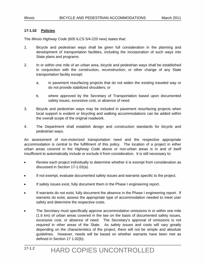
The Illinois Highway Code (605 ILCS 5/4-220 new) states that:
1. Bicycle and pedestrian ways shall be given full consideration in the planning and development of transportation facilities, including the incorporation of such ways into State plans and programs.
2. In or within one mile of an urban area, bicycle and pedestrian ways shall be established in conjunction with the construction, reconstruction, or other change of any State transportation facility except:
a. in pavement resurfacing projects that do not widen the existing traveled way or do not provide stabilized shoulders; or
b. where approved by the Secretary of Transportation based upon documented safety issues, excessive cost, or absence of need.
3. Bicycle and pedestrian ways may be included in pavement resurfacing projects when local support is evident or bicycling and walking accommodations can be added within the overall scope of the original roadwork.
4. The Department shall establish design and construction standards for bicycle and pedestrian ways.
An assessment of non-motorized transportation need and the respective appropriate accommodation is central to the fulfillment of this policy. The location of a project in either urban areas covered in the Highway Code above or non-urban areas is in and of itself insufficient to automatically include or exclude it from consideration. It is still necessary to:
Review each project individually to determine whether it is exempt from consideration as discussed in Section 17-1.02(a).
If not exempt, evaluate documented safety issues and warrants specific to the project.
If safety issues exist, fully document them in the Phase I engineering report.
If warrants do not exist, fully document the absence in the Phase I engineering report. If warrants do exist, assess the appropriate type of accommodation needed to meet user safety and determine the respective costs.
The Secretary must specifically approve accommodation omissions in or within one mile (1.6 km) of urban areas covered in the law on the basis of documented safety issues, excessive cost, or absence of need. The Secretary’s approval of omissions is not required in other areas of the State. As safety issues and costs will vary greatly depending on the characteristics of the project, there will not be simple and absolute guidelines. However, needs will be based on whether warrants have been met as defined in Section 17 1.02(b).
Illinois BICYCLE AND PEDESTRIAN ACCOMMODATIONS March 2011
17-1.3 HARD COPIES UNCONTROLLED
17-1.02(a) Exceptions to Consideration of Accommodations
Certain projects, depending on project type or location, can be immediately excluded from consideration of bicycle and pedestrian accommodations. As such, these exceptions require no warrant analyses or needs assessments:
projects along fully access controlled highway facilities on which bicycle and pedestrian access is prohibited (Illinois law allows the Department to restrict access by signing). Note: Consideration for bicycle and pedestrian accommodation crossing a fully access controlled highway will be granted an exception from consideration only if the traversing road is also a fully access controlled highway; and
existing pavement resurfacing projects that neither widen the existing traveled way nor provide stabilized shoulders (e.g., SMART, 3P). However, in the development of SMART and 3P projects, consider accommodations that do not change the overall scope of work (e.g., striping changes), but are consistent with Department criteria and the needs of bicyclists; see Section 17-2.02(g).
17-1.02(b) Partial Exceptions to Consideration of Accommodations
On existing pavement resurfacing projects that do not widen the existing traveled way nor provide stabilized shoulders (e.g., 3-P, SMART) bicycle accommodation will generally be limited to restriping and/or resigning existing bike lanes or shared roadways. However, consideration may also be given for new bicycle accommodation on 3-P or SMART projects where local support is evident and the accommodated project remains limited to the overall scope of the original roadwork. For example, reducing traveled way lane widths may provide sufficient space for adding bicycle lanes. Design criteria should be consistent with Section 17-2.01. Design studies are not required. The intent is to inform designers that some simple accommodations are possible within the strict design parameters of these projects.
Automatic exceptions are not considered simply because a roadway is identified in the Official Illinois Bicycle Maps as unsuitable for bicycling. Its current usability to a cyclist does not preclude that roadway project from bicycle consideration or this policy.
17-1.03 Bikeway Warrants - Needs Assessment
The Department shall provide adequate on-road or off-road accommodations for bicycle travel in highway projects when any of the following situations exist:
The highway or street is designated as a bikeway in a regionally or locally adopted bike plan or is published in a regionally or locally adopted map as a recommended bike route.
The projected two-way bicycle traffic volume (see Section 17-1.04) will approximate 25 ADT or more during the peak three months of the bicycling season five years after completion of the project.
The route provides primary access to a park, recreational area, school, or other significant destination.
Illinois BICYCLE AND PEDESTRIAN ACCOMMODATIONS March 2011
17-1.4 HARD COPIES UNCONTROLLED
The route provides unique access across a natural or man-made barrier (e.g., bridges over rivers, bridges over railroad yards, bridges over freeways or expressways, highways through a National Forest). Bicyclists will be accommodated on the bridge unless bicycles are otherwise prohibited to operate on the roadway approaches. See Sections 17-2.02(e) and 17-2.03(j) for bridge deck replacement or rehabilitation projects, or for culvert replacement projects. For projects that meet no other warrants, a minimum shoulder width of 4 ft (1.2 m) shall satisfy this warrant. For projects that meet this and other warrants, use the guidance provided in the Facility Selection Table in Figure 17-2.A.
The highway project will negatively affect the recreational or transportation utility of an independent bikeway or trail. Highway projects will negatively affect at-grade paths and trails when they are severed, when the projected roadway traffic volumes increase to a level that prohibits safe crossings at-grade, or when the widening of the roadway prohibits sufficient time for safe crossing.
When one or more of the warrants presented in Section 17-1.03 are met, appropriate accommodations shall be provided as defined later in this chapter in the Facility Selection Table in Figure 17-2.A. When bicycle accommodations will be included in the project, forward an electronic copy of the draft Phase I report to the Bureau of Design and Environment’s Bicycle and Pedestrian Coordinator. When projects do not meet warrants, send an electronic copy of Figures 17-1.A through 17-1.D to the Bicycle and Pedestrian Coordinator explaining the assessment of the warrants and to obtain concurrence. Exceptions to these design treatments either on the basis of cost or user safety require concurrence by the Bicycle and Pedestrian Coordinator and will be granted at coordination meetings after a sufficient review period. Total omissions on the basis of need, cost or user safety and that are within one mile of an urban area will require concurrence of the Secretary. Signed documentation of the Secretary’s concurrence shall be included in the draft Phase I report.
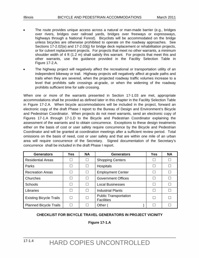
Generators Yes NA Generators Yes NA Residential Areas Shopping Centers
Parks Hospitals
Recreation Areas Employment Center
Churches Government Offices
Schools Local Businesses
Libraries Industrial Plants
Existing Bicycle Trails Public Transportation Facilities
Planned Bicycle Trails Other ( )
CHECKLIST FOR BICYCLE TRAVEL GENERATORS IN PROJECT VICINITY
Figure 17-1.A
Illinois BICYCLE AND PEDESTRIAN ACCOMMODATIONS March 2011
17-1.5 HARD COPIES UNCONTROLLED
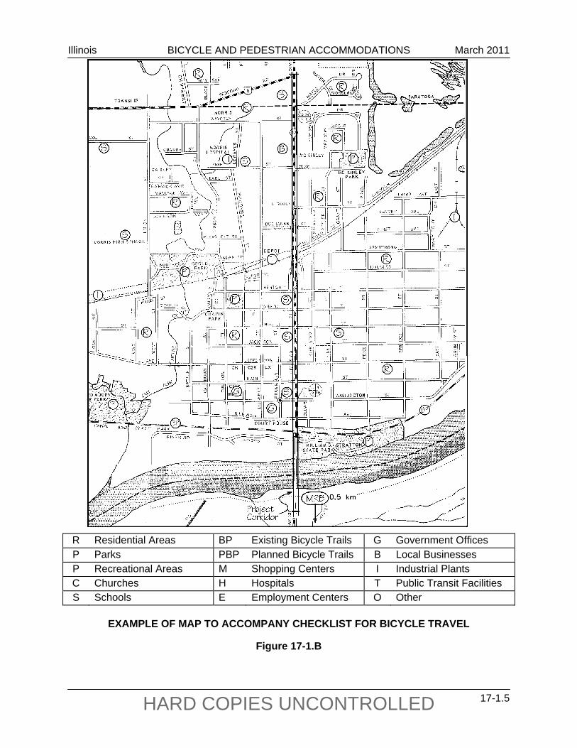
R Residential Areas BP Existing Bicycle Trails G Government Offices P Parks PBP Planned Bicycle Trails B Local Businesses P Recreational Areas M Shopping Centers I Industrial Plants C Churches H Hospitals T Public Transit Facilities S Schools E Employment Centers O Other
EXAMPLE OF MAP TO ACCOMPANY CHECKLIST FOR BICYCLE TRAVEL
Figure 17-1.B
Illinois BICYCLE AND PEDESTRIAN ACCOMMODATIONS March 2011
17-1.6 HARD COPIES UNCONTROLLED
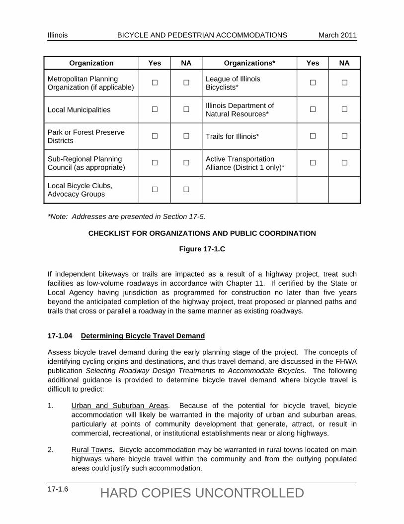
Organization Yes NA Organizations* Yes NA
Metropolitan Planning Organization (if applicable) League of Illinois
Bicyclists*
Local Municipalities Illinois Department of Natural Resources*
Park or Forest Preserve Districts Trails for Illinois*
Sub-Regional Planning Council (as appropriate) Active Transportation
Alliance (District 1 only)*
Local Bicycle Clubs, Advocacy Groups
*Note: Addresses are presented in Section 17-5.
CHECKLIST FOR ORGANIZATIONS AND PUBLIC COORDINATION
Figure 17-1.C If independent bikeways or trails are impacted as a result of a highway project, treat such facilities as low-volume roadways in accordance with Chapter 11. If certified by the State or Local Agency having jurisdiction as programmed for construction no later than five years beyond the anticipated completion of the highway project, treat proposed or planned paths and trails that cross or parallel a roadway in the same manner as existing roadways.
17-1.04 Determining Bicycle Travel Demand
Assess bicycle travel demand during the early planning stage of the project. The concepts of identifying cycling origins and destinations, and thus travel demand, are discussed in the FHWA publication Selecting Roadway Design Treatments to Accommodate Bicycles. The following additional guidance is provided to determine bicycle travel demand where bicycle travel is difficult to predict:
1. Urban and Suburban Areas. Because of the potential for bicycle travel, bicycle accommodation will likely be warranted in the majority of urban and suburban areas, particularly at points of community development that generate, attract, or result in commercial, recreational, or institutional establishments near or along highways.
2. Rural Towns. Bicycle accommodation may be warranted in rural towns located on main highways where bicycle travel within the community and from the outlying populated areas could justify such accommodation.
Illinois BICYCLE AND PEDESTRIAN ACCOMMODATIONS March 2011
17-1.7 HARD COPIES UNCONTROLLED
Route __________________________
Section __________________________
County __________________________
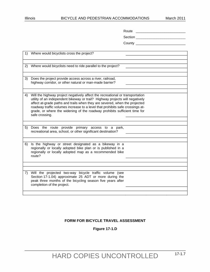
1) Where would bicyclists cross the project? 2) Where would bicyclists need to ride parallel to the project? 3) Does the project provide access across a river, railroad, highway corridor, or other natural or man-made barrier?
4) Will the highway project negatively affect the recreational or transportation
utility of an independent bikeway or trail? Highway projects will negatively affect at-grade paths and trails when they are severed, when the projected roadway traffic volumes increase to a level that prohibits safe crossings at-grade, or where the widening of the roadway prohibits sufficient time for safe crossing.
5) Does the route provide primary access to a park,
recreational area, school, or other significant destination?
6) Is the highway or street designated as a bikeway in a
regionally or locally adopted bike plan or is published in a regionally or locally adopted map as a recommended bike route?
7) Will the projected two-way bicycle traffic volume (see
Section 17-1.04) approximate 25 ADT or more during the peak three months of the bicycling season five years after completion of the project.
FORM FOR BICYCLE TRAVEL ASSESSMENT
Figure 17-1.D
Illinois BICYCLE AND PEDESTRIAN ACCOMMODATIONS March 2011
17-1.8 HARD COPIES UNCONTROLLED
3. Rural Highway Projects. Rural highway projects that provide unique access over a major barrier (e.g., river) or that connect an urban area to a rural attraction (e.g., park) would be expected to meet the warrants.
4. Unpopulated Rural Areas. In unpopulated rural areas, typical origins and destinations are far less frequent. Thus, the need for bicycle accommodation may not be warranted.
17-1.04(a) Assessment of Bicycle Travel Within Highway Projects
Bicycle origins and destinations should be reviewed for each project and noted in a checklist format unless the designer is satisfied that other warrants have already been met. If so, this travel demand assessment is not required. All checklists are in Section 17-6. Such information provides the basis for evaluating whether or not the travel demand warrant for bicycle accommodation has been met. This section provides two checklists, an example map, and a travel assessment form that should be included in all Phase I reports, except for projects excluded in Section 17-1.02(a).
17-1.04(b) Bicycle Travel Generators in Project Vicinity
Review and record the potential bicycle travel generators in the vicinity of the project, such as those shown in the checklist in Figure 17-1.A. Note on the checklist the types of generators within 1 mile (2 km) of the project corridor. To the Phase I report, attach a map of this area showing the general location of these generators as illustrated in Figure 17-1.B. Sections of Municipal or Township maps are acceptable, as well as photocopies of aerial photos. The map will serve to indicate where bicyclists will cross or ride along the corridor.
17-1.04(c) Public Coordination
The organizations presented in Figure 17-1.C shall be contacted to assess any nearby bicycle travel or planned development of recreational trails or other generators. Include documentation of coordination in the Phase I report.
17-1.04(d) Bicycle Travel Assessment
Based on the bicycle travel indicators presented in Sections 17-1.04(b) and 17-1.04(c), address the questions in the bicycle travel assessment form (see Figure 17-1.D) and attach the completed form to the Phase I report.
17-1.05 Maintenance and Jurisdiction
Responsibility for ongoing maintenance of bikeway facilities within the roadway surface is assumed to be an integral part of roadway maintenance.
Illinois BICYCLE AND PEDESTRIAN ACCOMMODATIONS March 2011
17-1.9 HARD COPIES UNCONTROLLED
Responsibility for maintenance of bikeway and pedestrian facilities separated from the roadway surface should be delegated by agreement with local/State jurisdictions or others early in the planning process; see Chapter 5.
17-1.06 Right-of-Way
Acquire right-of-way for bikeway facilities in accordance with existing IDOT land acquisition policies and procedures. Additional right-of-way required for bikeway purposes should be purchased in conjunction with the right-of-way purchase of the overall roadway improvement.
17-1.07 Funding
Bicycle facilities for the safe travel of bicyclists within an improvement corridor, are considered an integral part of a highway project for funding purposes, and thus are eligible for cost participation as discussed in Chapter 5. If conditions within the roadway prohibit the inclusion of adequate bicycle accommodations, necessary off-roadway accommodations shall be included where they can be accommodated.
Accommodations beyond those that are determined necessary from the Facility Selection Table in Figure 17-2.A may be desired or preferred by local officials, and the cost difference could be funded through several options as follows:
initiated by others than IDOT and submitted as a candidate for the Transportation Enhancement Program funding (see Chapter 18);
initiated by others than IDOT and submitted for consideration from other appropriate Federal funding categories (e.g., the Congestion Mitigation and Air Quality (CMAQ) or various Surface Transportation Program (STP) categories); or
initiated by others than IDOT and funded entirely through outside governmental organizations.

Illinois BICYCLE AND PEDESTRIAN ACCOMMODATIONS March 2011
17-1.10 HARD COPIES UNCONTROLLED
Illinois BICYCLE AND PEDESTRIAN ACCOMMODATIONS February 2013
17-2.1 HARD COPIES UNCONTROLLED
17-2 DESIGN CRITERIA FOR BICYCLE FACILITIES
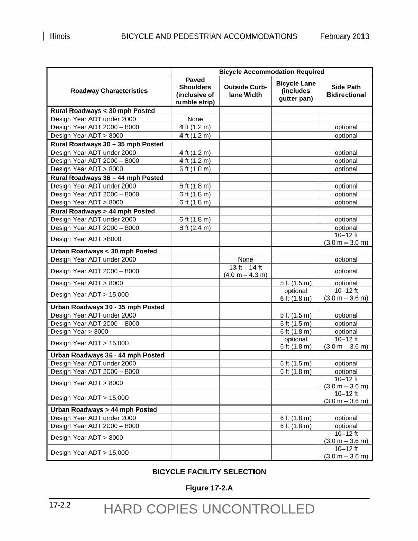
The Department utilizes the AASHTO publication Guide for the Development of Bicycle Facilities as the basis for design guidance. In addition, the Bicycle Facility Selection Table, Figure 17-2.A, is based on the FHWA publication Selecting Roadway Design Treatments to Accommodate Bicycles. Also, coordinate bicycle facility design with the cross section criteria presented in Part IV “Roadway Design Elements” and Part V “Design of Highway Types.”
17-2.01 Documentation
When one or more of the warrants presented in Section 17-1.03 are met, appropriate accommodations shall be provided as defined later in this chapter in the Facility Selection Table in Figure 17-2.A. When bicycle accommodations will be included in the project, forward an electronic copy of the draft Phase I report to the Bureau of Design and Environment’s Bicycle and Pedestrian Coordinator. When projects do not meet warrants, send an electronic copy of Figures 17-1.A through 17-1.D to the Bicycle and Pedestrian Coordinator explaining the assessment of the warrants and to obtain concurrence. Exceptions to these design treatments either on the basis of cost or user safety require concurrence by the Bicycle and Pedestrian Coordinator and will be granted at coordination meetings after a sufficient review period. Total omissions on the basis of need, cost or user safety and that are within one mile of an urban area will require concurrence of the Secretary. Signed documentation of the Secretary’s concurrence shall be included in the draft Phase I report.
There are situations in which the principles of Context Sensitive Solutions (CSS) and Complete Streets conflict. In instances where the requirements of the Complete Streets Law run counter to the consensus view of project stakeholders, the Regional Engineer will determine the accommodation solution, or lack thereof, in consultation with the Bicycle and Pedestrian Coordinator.
After need has been established and the appropriate accommodation has been identified using Figure 17-2.A, it is the responsibility of the district to convey this information to the appropriate local agency. Not all accommodations require a local match or maintenance participation as identified in Chapter 5. In projects that require local participation, if the local agency chooses not to participate in the bicycle or pedestrian accommodation, the Department will request that that local agency pass a local resolution indicating their non-participation and have this noted in the Phase I report. Proposed resolution language is included in Section 17-7. Without local agency participation, the Department will consider the highest and best accommodation feasible.
If it is determined in the Phase I report that the recommended accommodation in the Facility Selection Table cannot be built without excessive cost, local support, or disruptive ROW considerations then the next highest and best accommodation shall be considered that can achieve the highest safety for the user and best meets the project’s cost, local support, and ROW considerations. Selection of next highest and best accommodations shall be determined on a case-by-case basis by the district as many variables will need to be considered. This may become an iterative process when considering all project variables.
Illinois BICYCLE AND PEDESTRIAN ACCOMMODATIONS February 2013
17-2.2 HARD COPIES UNCONTROLLED
Bicycle Accommodation Required
Roadway Characteristics Paved
Shoulders (inclusive of rumble strip)
Outside Curb-lane Width
Bicycle Lane (includes
gutter pan) Side Path
Bidirectional
Rural Roadways < 30 mph Posted Design Year ADT under 2000 None Design Year ADT 2000 – 8000 4 ft (1.2 m) optional Design Year ADT > 8000 4 ft (1.2 m) optional Rural Roadways 30 – 35 mph Posted Design Year ADT under 2000 4 ft (1.2 m) optional Design Year ADT 2000 – 8000 4 ft (1.2 m) optional Design Year ADT > 8000 6 ft (1.8 m) optional Rural Roadways 36 – 44 mph Posted Design Year ADT under 2000 6 ft (1.8 m) optional Design Year ADT 2000 – 8000 6 ft (1.8 m) optional Design Year ADT > 8000 6 ft (1.8 m) optional Rural Roadways > 44 mph Posted Design Year ADT under 2000 6 ft (1.8 m) optional Design Year ADT 2000 – 8000 8 ft (2.4 m) optional
Design Year ADT >8000 10–12 ft(3.0 m – 3.6 m)
Urban Roadways < 30 mph Posted Design Year ADT under 2000 None optional
Design Year ADT 2000 – 8000 13 ft – 14 ft (4.0 m – 4.3 m) optional
Design Year ADT > 8000 5 ft (1.5 m) optional
Design Year ADT > 15,000 optional 6 ft (1.8 m)
10–12 ft(3.0 m – 3.6 m)
Urban Roadways 30 - 35 mph Posted Design Year ADT under 2000 5 ft (1.5 m) optional Design Year ADT 2000 – 8000 5 ft (1.5 m) optional Design Year > 8000 6 ft (1.8 m) optional
Design Year ADT > 15,000 optional 6 ft (1.8 m)
10–12 ft(3.0 m – 3.6 m)
Urban Roadways 36 - 44 mph Posted Design Year ADT under 2000 5 ft (1.5 m) optional Design Year ADT 2000 – 8000 6 ft (1.8 m) optional
Design Year ADT > 8000 10–12 ft(3.0 m – 3.6 m)
Design Year ADT > 15,000 10–12 ft(3.0 m – 3.6 m)
Urban Roadways > 44 mph Posted Design Year ADT under 2000 6 ft (1.8 m) optional Design Year ADT 2000 – 8000 6 ft (1.8 m) optional
Design Year ADT > 8000 10–12 ft(3.0 m – 3.6 m)
Design Year ADT > 15,000 10–12 ft (3.0 m – 3.6 m)
BICYCLE FACILITY SELECTION
Figure 17-2.A
Illinois BICYCLE AND PEDESTRIAN ACCOMMODATIONS February 2013
17-2.3 HARD COPIES UNCONTROLLED
17-2.02 On-Road Accommodations
17-2.02(a) On-Road Bikeways on Rural Roadways
An on-road bicycle accommodation on rural cross sections consists of providing a paved shoulder. Paved shoulders can accommodate most types of bicycle travel very efficiently and offer benefits beyond accommodating bicyclists (e.g., added safety, reduced maintenance, rural mail delivery). Use Figure 17-2.A to determine the appropriate accommodation/shoulder width. When rumble strips are installed in a paved shoulder which serves as a bicycle accommodation and the width of the paved shoulder is 6 ft (1.8 m) or less, the 8 in (200 mm) rumble strip design should used to minimize the impact to the accommodation.
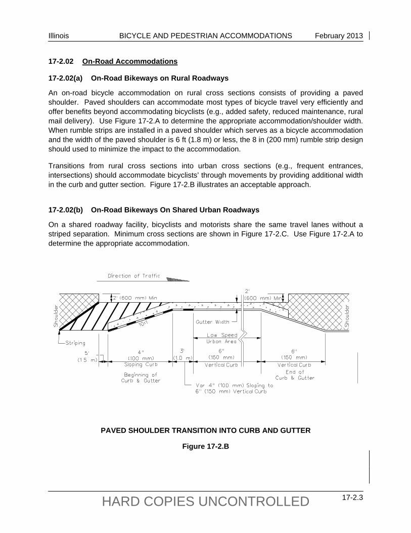
Transitions from rural cross sections into urban cross sections (e.g., frequent entrances, intersections) should accommodate bicyclists’ through movements by providing additional width in the curb and gutter section. Figure 17-2.B illustrates an acceptable approach.
17-2.02(b) On-Road Bikeways On Shared Urban Roadways
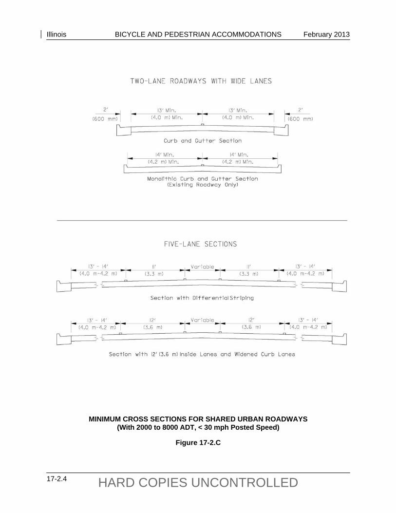
On a shared roadway facility, bicyclists and motorists share the same travel lanes without a striped separation. Minimum cross sections are shown in Figure 17-2.C. Use Figure 17-2.A to determine the appropriate accommodation.
PAVED SHOULDER TRANSITION INTO CURB AND GUTTER
Figure 17-2.B
Illinois BICYCLE AND PEDESTRIAN ACCOMMODATIONS February 2013
17-2.4 HARD COPIES UNCONTROLLED
MINIMUM CROSS SECTIONS FOR SHARED URBAN ROADWAYS (With 2000 to 8000 ADT, < 30 mph Posted Speed)
Figure 17-2.C
Illinois BICYCLE AND PEDESTRIAN ACCOMMODATIONS February 2013
17-2.5 HARD COPIES UNCONTROLLED
Measure the width of the lane from the lane stripe to the joint between the pavement and the gutter. If no joint exists, as with monolithic pavement, take the measurement to the face of the curb. Bicycles, because of their narrow tires, cannot be expected to be ridden on or near a longitudinal pavement joint because of the potential for catching the wheel in the joint and throwing a rider into traffic.
Gutter widths are not considered acceptable for bicycle travel. A bicyclist riding in the gutter is often forced to leave this area because of debris or broken pavement. If the pavement/gutter joint is vertically uneven or has separated from the gutter, a bicyclist can become trapped and forced to make unsafe maneuvers.
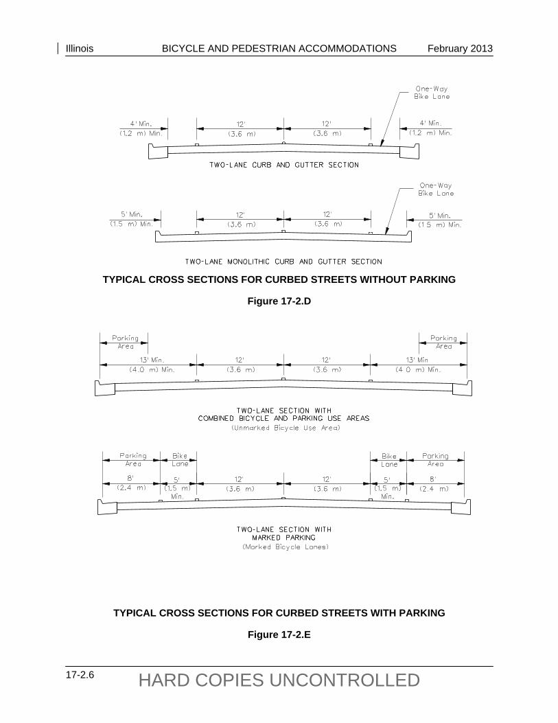
17-2.02(c) On-Road Marked Bicycle Lanes on Urban Roadways
Bicycle lanes that are marked on curbed streets serve to separate bicycle traffic from motor vehicle traffic. Use Figure 17-2.A to determine the appropriate accommodation.
The following are typical cross section requirements:
On curbed streets without parking, locate the bicycle lane next to the gutter, as shown in Figure 17-2.D.
Where parking is permitted, locate the bicycle lane between the parking lane and the through traffic lanes as shown in Figure 17-2.E.
Where parking is allowed on a street, provide additional parking-lane width, above the
required minimum, under the following conditions:
where there is frequent parking turnover, where parked vehicles are mostly commercial vehicles, or where posted motor vehicle speeds equal 45 mph.
Design bicycle lanes as one-way facilities that carry bicycle traffic in the same direction as adjacent motor vehicle traffic. Two-way bicycle lanes on one side of the roadway (without physical separation) are unacceptable because they promote riding against the flow of motor vehicle traffic. Wrong-way riding is a major cause of bicycle crashes nationally and violates the Illinois Vehicle Code (625 ILCS 5/11-1505). Locate one-way bicycle lanes that are on one-way streets on the right side of the street, except in areas where placing the bicycle lane on the left will decrease the number of conflicts (e.g., those caused by heavy bus traffic).
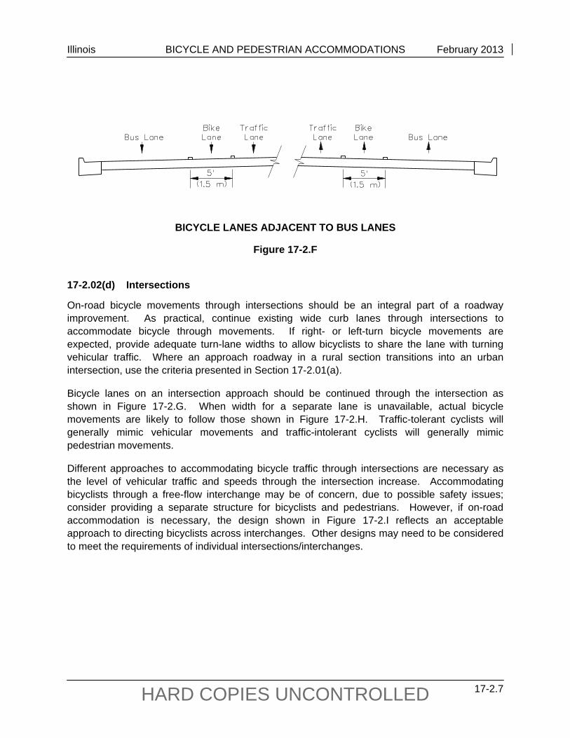
Place bicycle lanes that are adjacent to dedicated bus lanes between the vehicular traffic lane and the bus lane as shown in Figure 17-2.F. Where roadway width is limited, bicycles and buses may share an outside lane with a minimum width of 16.5 ft (5 m) to the curb face.
Illinois BICYCLE AND PEDESTRIAN ACCOMMODATIONS February 2013
17-2.6 HARD COPIES UNCONTROLLED
TYPICAL CROSS SECTIONS FOR CURBED STREETS WITHOUT PARKING
Figure 17-2.D
TYPICAL CROSS SECTIONS FOR CURBED STREETS WITH PARKING
Figure 17-2.E
Illinois BICYCLE AND PEDESTRIAN ACCOMMODATIONS February 2013
17-2.7 HARD COPIES UNCONTROLLED
BICYCLE LANES ADJACENT TO BUS LANES
Figure 17-2.F 17-2.02(d) Intersections
On-road bicycle movements through intersections should be an integral part of a roadway improvement. As practical, continue existing wide curb lanes through intersections to accommodate bicycle through movements. If right- or left-turn bicycle movements are expected, provide adequate turn-lane widths to allow bicyclists to share the lane with turning vehicular traffic. Where an approach roadway in a rural section transitions into an urban intersection, use the criteria presented in Section 17-2.01(a).
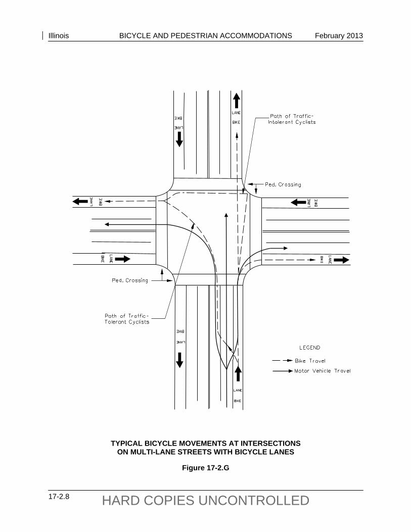
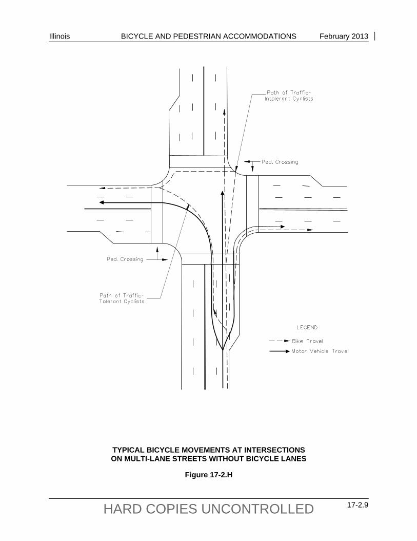
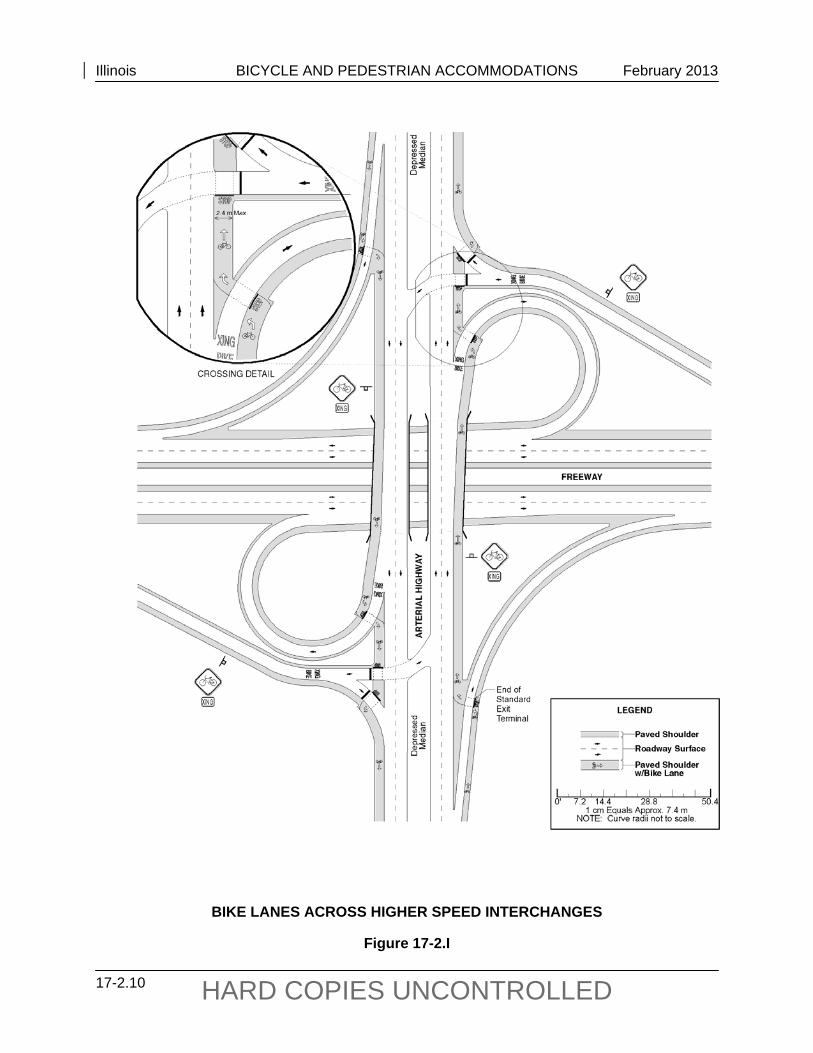
Bicycle lanes on an intersection approach should be continued through the intersection as shown in Figure 17-2.G. When width for a separate lane is unavailable, actual bicycle movements are likely to follow those shown in Figure 17-2.H. Traffic-tolerant cyclists will generally mimic vehicular movements and traffic-intolerant cyclists will generally mimic pedestrian movements.
Different approaches to accommodating bicycle traffic through intersections are necessary as the level of vehicular traffic and speeds through the intersection increase. Accommodating bicyclists through a free-flow interchange may be of concern, due to possible safety issues; consider providing a separate structure for bicyclists and pedestrians. However, if on-road accommodation is necessary, the design shown in Figure 17-2.I reflects an acceptable approach to directing bicyclists across interchanges. Other designs may need to be considered to meet the requirements of individual intersections/interchanges.
Illinois BICYCLE AND PEDESTRIAN ACCOMMODATIONS February 2013
17-2.8 HARD COPIES UNCONTROLLED
TYPICAL BICYCLE MOVEMENTS AT INTERSECTIONS ON MULTI-LANE STREETS WITH BICYCLE LANES
Figure 17-2.G
Illinois BICYCLE AND PEDESTRIAN ACCOMMODATIONS February 2013
17-2.9 HARD COPIES UNCONTROLLED
TYPICAL BICYCLE MOVEMENTS AT INTERSECTIONS ON MULTI-LANE STREETS WITHOUT BICYCLE LANES
Figure 17-2.H
Illinois BICYCLE AND PEDESTRIAN ACCOMMODATIONS February 2013
17-2.10 HARD COPIES UNCONTROLLED
BIKE LANES ACROSS HIGHER SPEED INTERCHANGES
Figure 17-2.I
Illinois BICYCLE AND PEDESTRIAN ACCOMMODATIONS February 2013
17-2.11 HARD COPIES UNCONTROLLED
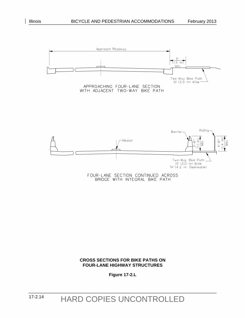
17-2.02(e) Bikeway on Highway Structures
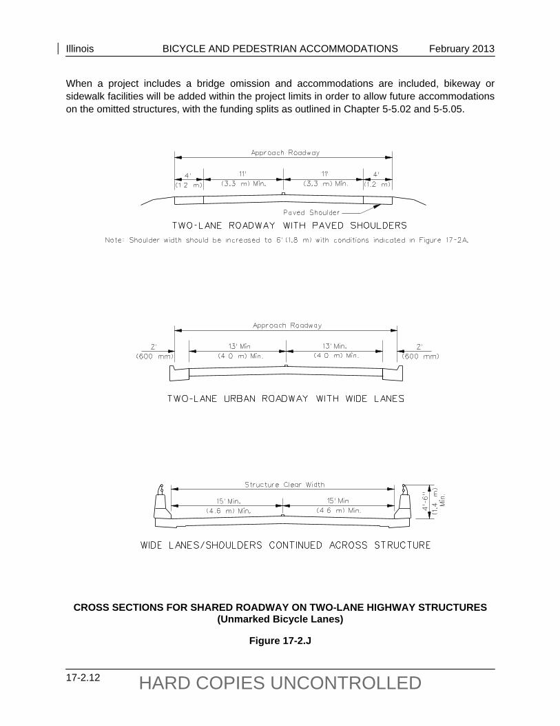
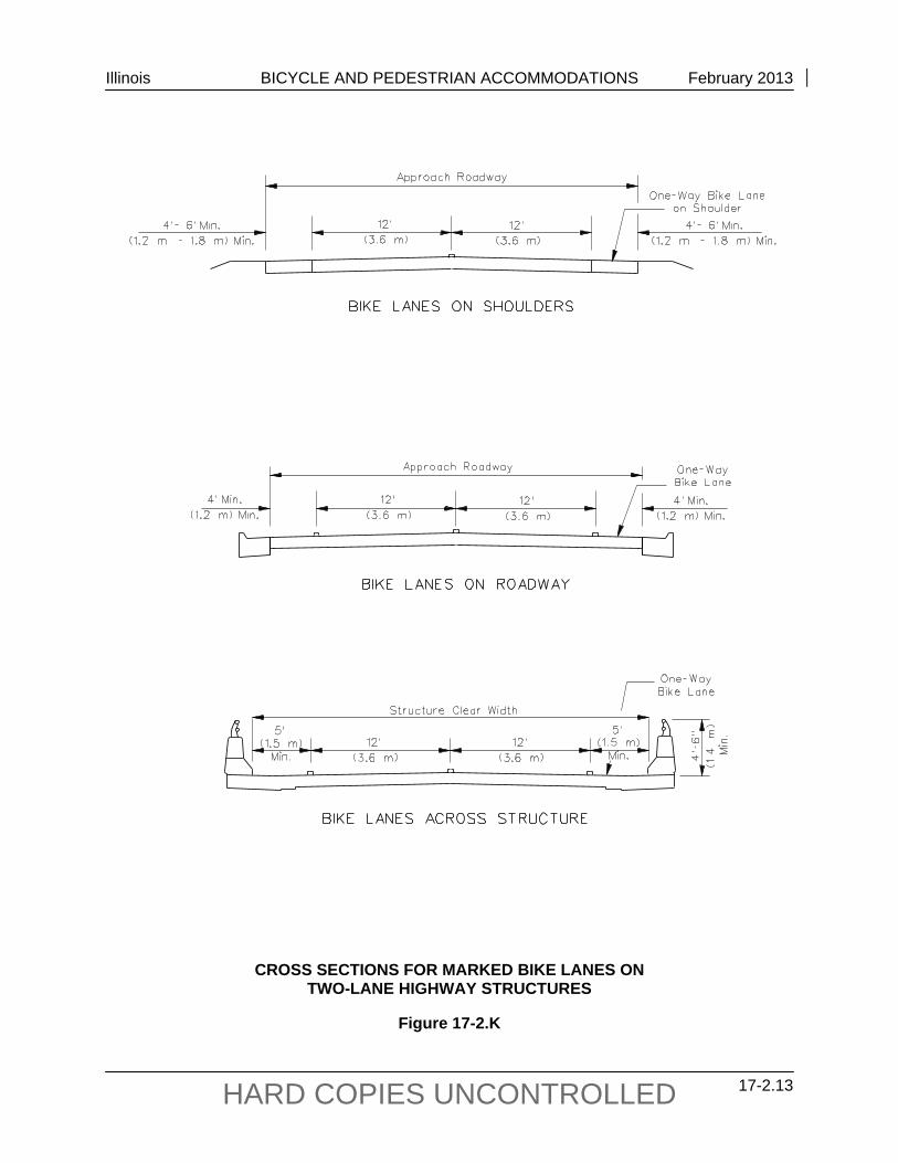
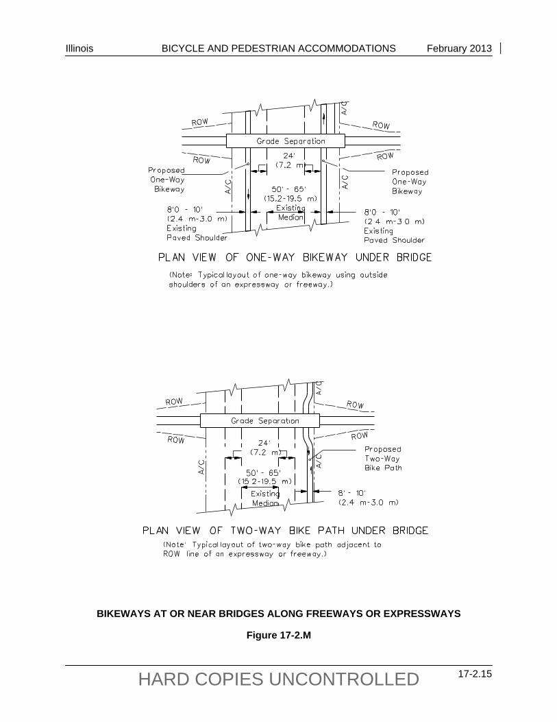
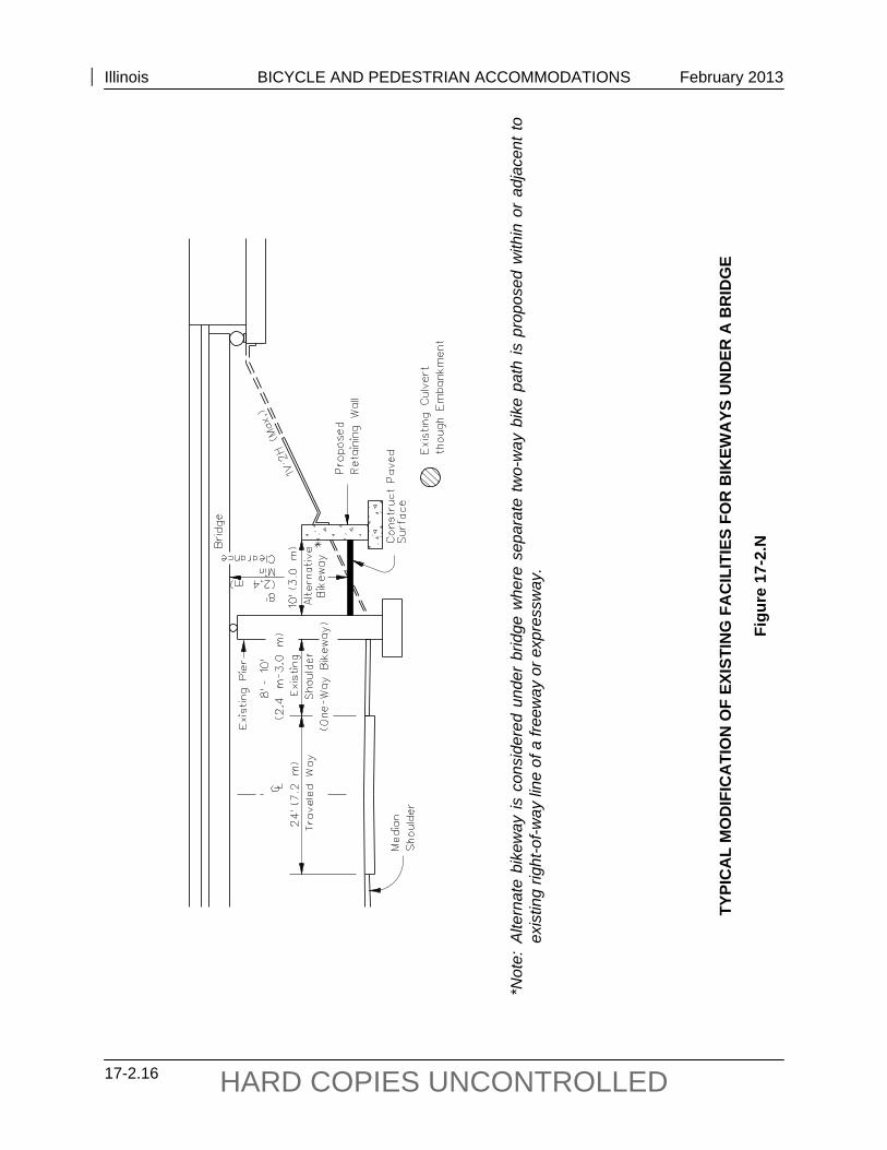
Bicycle accommodations on approach roadways should be carried across structures. The width of new highway structures should, at a minimum, equal the width of the traveled way plus the width of approaching bicycle lanes and/or sidewalks. Minimum cross sections for roadways and structures will vary significantly depending on the type of bicycle facility being accommodated. Several examples of minimum cross sections for shared roadways, bicycle lanes and bicycle paths are shown in Figures 17-2.J through 17-.2.L. In addition, the criteria for accommodating bikeways at or near bridges along freeways and expressways are illustrated in Figure 17-2.M. Figure 17-2.N presents a typical modification of existing facilities for bikeways under a bridge.
Where it is necessary to retrofit a separated bicycle path (see Section 17-2.02) onto an existing highway bridge, several alternatives should be considered in light of what the geometrics of the bridge will allow. One option is to carry the bicycle path across one side of the structure. This should be considered where:
the bridge facility will connect to a bicycle path at both ends,
sufficient width exists on that side of the bridge or can be obtained by widening or restriping lanes, and
provisions are made to physically separate bicycle traffic from motor vehicle traffic.
Another option is to use existing sidewalks as one-way or two-way facilities. This may be advisable where:
conflicts between bicyclists and pedestrians will not exceed tolerable limits, and the existing sidewalks are adequately wide. If the existing facility cannot provide adequate accommodation (per widths indicated in this section), appropriately sign the facility to warn users of the deficiencies or require bicyclists to dismount and cross the structure as a pedestrian. Section 17-2.03(i) provides additional design guidance for structures on bicycle paths. The Department policy on railing specifies a 4-6 (1.4 m) outside railing height on roadway structures. Bridge railing on off-road-shared-use paths must meet a 3-6 (1.1 m) minimum rail height requirement.
Bridge deck replacement or rehabilitation projects are not intended to widen the traveled way but rather improve the roadway surface on the structure. Bridge width is limited to the existing components of the substructure and as such may not allow the bicycle accommodations called for in the Facility Selection Table, Figure 17-2.A. However, those structures should be reviewed and widened as much as safety will allow. For the purposes of this policy, culverts are not considered structures as they can be extended to meet future needs. For any improvement that includes existing or new culverts, those culverts shall be extended to accommodate the bicycle accommodation, if bicycle warrants are met. If no warrants are met then no accommodation is required.
Illinois BICYCLE AND PEDESTRIAN ACCOMMODATIONS February 2013
17-2.12 HARD COPIES UNCONTROLLED
When a project includes a bridge omission and accommodations are included, bikeway or sidewalk facilities will be added within the project limits in order to allow future accommodations on the omitted structures, with the funding splits as outlined in Chapter 5-5.02 and 5-5.05.
CROSS SECTIONS FOR SHARED ROADWAY ON TWO-LANE HIGHWAY STRUCTURES (Unmarked Bicycle Lanes)
Figure 17-2.J
Illinois BICYCLE AND PEDESTRIAN ACCOMMODATIONS February 2013
17-2.13 HARD COPIES UNCONTROLLED
CROSS SECTIONS FOR MARKED BIKE LANES ON TWO-LANE HIGHWAY STRUCTURES
Figure 17-2.K
Illinois BICYCLE AND PEDESTRIAN ACCOMMODATIONS February 2013
17-2.14 HARD COPIES UNCONTROLLED
CROSS SECTIONS FOR BIKE PATHS ON FOUR-LANE HIGHWAY STRUCTURES
Figure 17-2.L
Illinois BICYCLE AND PEDESTRIAN ACCOMMODATIONS February 2013
17-2.15 HARD COPIES UNCONTROLLED
BIKEWAYS AT OR NEAR BRIDGES ALONG FREEWAYS OR EXPRESSWAYS
Figure 17-2.M
Illinois BICYCLE AND PEDESTRIAN ACCOMMODATIONS February 2013
17-2.16 HARD COPIES UNCONTROLLED
*N
ote:
Alte
rnat
e bi
kew
ay is
con
side
red
unde
r br
idge
whe
re s
epar
ate
two-
way
bik
e pa
th is
pro
pose
d w
ithin
or
adja
cent
to
exis
ting
right
-of-w
ay li
ne o
f a fr
eew
ay o
r exp
ress
way
.
TYPI
CA
L M
OD
IFIC
ATI
ON
OF
EXIS
TIN
G F
AC
ILIT
IES
FOR
BIK
EWA
YS U
ND
ER A
BR
IDG
E
Figu
re 1
7-2.
N
Illinois BICYCLE AND PEDESTRIAN ACCOMMODATIONS February 2013
17-2.17 HARD COPIES UNCONTROLLED
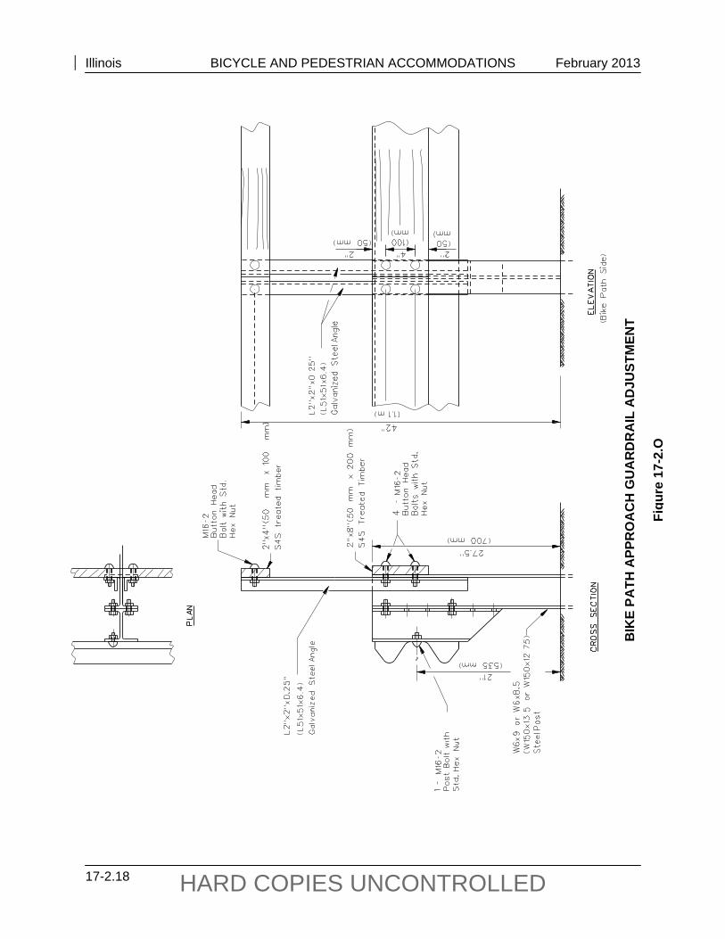
17-2.02(f) Bikeway Adjacent to Highways
Railings or barriers, 3.5 ft (1.1 m) high, are required wherever a two-way bike path is proposed within 5 ft (1.5 m) of the face of curb on an urban roadway section, or within 10 ft (3 m) from the traveled way on a rural roadway section. In addition, approach guardrails should be extended to a 3.5 ft (1.1 m) height until the bike path is more than 5 ft (1.5 m) from the edge of the traveled way. The requisite extension on a standard guardrail to extend its height to 3.5 ft (1.1 m) is shown in Figure 17-2.O. The width of the two-way bike path is shown in Figure 17-2.A. Separation railings are not required when bicycle traffic flows in the same direction as vehicular traffic.
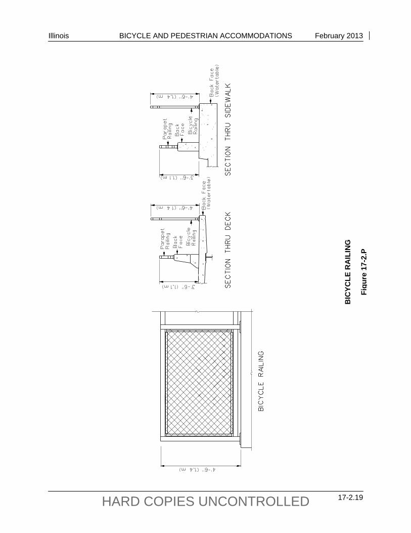
Railings and barriers that provide a separation between the roadway and a bike path are primarily intended to prevent the bicyclist from falling over the railing into opposing traffic. Thus, the type of railing provided is dependent on its proximity to vehicular traffic and its ability to deflect vehicular impacts. For example, railings located on top of a raised sidewalk edge will require an impact resistance different than railings located adjacent to the traffic lane. The designer of the railing also should consider sight impediments the railing might impose. Examples of such railings are shown in Figure 17-2.P.
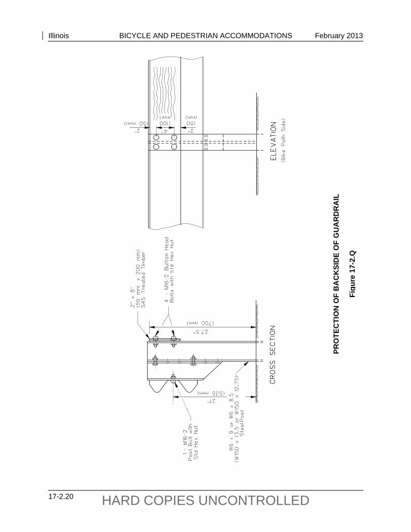
All vertical surfaces within a 2 ft (600 mm) clear area adjacent to the bicyclists’ path should be smooth to avoid snagging of clothing or incurring abrasive injuries from contact with the surface. For example, protect the sharp edges of the backside of a guardrail located within 2 ft (600 mm) of the edge of a bikeway by smooth planking or rub rail as shown in Figure 17-2.Q; however, no modifications shall be made within the length of guardrail terminals.
17-2.02(g) Additional Considerations for Accommodations on Existing Roadways
Bicycles also can be accommodated on a roadway by marking or re-marking the pavement to increase the width of the curb lane or to add bike lanes. For example, it may be feasible to:
reduce the width of inside traffic lanes in accordance with IDOT and AASHTO criteria;
reduce the median width, especially with the removal of raised curb medians, or the two-way center turn lane width;
remove parking, possibly in conjunction with providing off-street parking;
reduce the number of traffic lanes (e.g., if one-way couples are created or if a parallel roadway improvement reduces the traffic demand on an adjacent street that is more suited for bicycle travel, subject to analysis of capacity/safety/operational needs); and
where grades for on-road bicycle facilities exceed bike path grades in Figure 17-2.FF, consider using signs to alert bicyclists of upcoming grades.
Illinois BICYCLE AND PEDESTRIAN ACCOMMODATIONS February 2013
17-2.18 HARD COPIES UNCONTROLLED
BIK
E PA
TH A
PPR
OA
CH
GU
AR
DR
AIL
AD
JUST
MEN
T
Figu
re 1
7-2.
O
Illinois BICYCLE AND PEDESTRIAN ACCOMMODATIONS February 2013
17-2.19 HARD COPIES UNCONTROLLED
BIC
YCLE
RA
ILIN
G
Figu
re 1
7-2.
P
Illinois BICYCLE AND PEDESTRIAN ACCOMMODATIONS February 2013
17-2.20 HARD COPIES UNCONTROLLED
PRO
TEC
TIO
N O
F B
AC
KSI
DE
OF
GU
AR
DR
AIL
Figu
re 1
7-2.
Q
Illinois BICYCLE AND PEDESTRIAN ACCOMMODATIONS February 2013
17-2.21 HARD COPIES UNCONTROLLED
17-2.02(h) Incidental Design Factors
Regardless of the type of improvement being developed, the following items always should be considered:
1. Drainage Grates. Drainage grates and utility covers on roads, bridge approaches, and bridges can be hazardous to bicyclists. Bicycles often have narrow tires and no shock absorbent systems, and therefore are more sensitive to older elongated-slot style drainage inlets and irregularities on the pavement surface. Current IDOT drainage grate designs suitable for bicycle travel include Types 3, 3V, 4, 9, 10, 11, 11V, 23, and 24. Types 20, 21, and 22 are conditionally acceptable if the vane length is perpendicular to bicycle travel. Other grates are acceptable if the opening slots do not exceed 6¼ L x 1½ W (159 mm L x 38 mm). In addition, grates and utility covers located in the bicyclists’ expected path should be flush with the pavement.
With pavement overlay projects, replace utility covers and non-conforming drainage grates and adjust them flush with the new surface. Project limits may be extended within reasonable distances (i.e., one block or more) to replace additional non-conforming drainage grates that present obvious hazards to bicyclists.
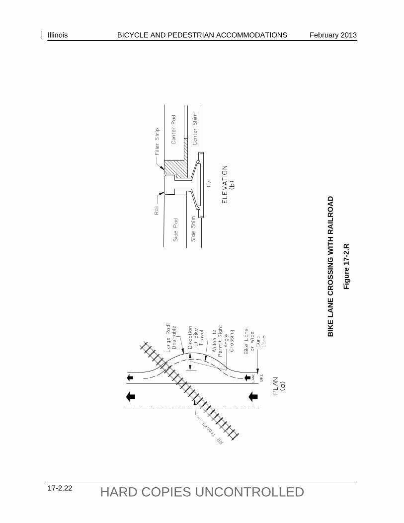
Railroad Crossings. Bicyclists should be able to cross railroad tracks at or near a right angle to minimize the potential for a bicycle’s front wheel to become trapped in the flangeway, which would cause loss of steering control. The potential for a bicyclist’s front wheel to be trapped in the rail flangeway increases when the angle of approach deviates greatly (20°) from 90°. When the crossing angle is less than 45°, consider widening the outside lane, shoulder, or bicycle lane to improve the angle of approach (see Figure 17-2.R(a)). Where this is not practical, consider using commercially available compressible flangeway fillers, such as that shown in Figure 17-2.R(b), to provide a smooth transition over the rails. Design the bicycle portion of the pavement surface so that it is the same elevation as the rails and consistent with the vehicular crossing surface. Remove abandoned tracks, if practical, to eliminate the hazard.
2. Pavement Structure Considerations. Consider the following factors related to pavement structures:
a. Joints and Drop-Offs. In new construction, pavement surface irregularities can cause a bicyclist to lose control and result in a crash. Because bicycle tires may be as narrow as 1 in (25 mm), gaps between pavement slabs and gutters or drop-offs at overlays, especially parallel to the direction of travel, can trap a bicycle wheel and result in loss of control. This loss of control can cause a bicyclist to fall or swerve into the path of motor vehicle traffic. To the extent practical, pavement surfaces should be free of irregularities and the edge of the pavement should be uniform in width. To assure pavement suitability, overlay projects should consider options to scarify the old pavement up to the gutter edge.
Illinois BICYCLE AND PEDESTRIAN ACCOMMODATIONS February 2013
17-2.22 HARD COPIES UNCONTROLLED
BIK
E LA
NE
CR
OSS
ING
WIT
H R
AIL
RO
AD
Figu
re 1
7-2.
R
Illinois BICYCLE AND PEDESTRIAN ACCOMMODATIONS February 2013
17-2.23 HARD COPIES UNCONTROLLED
b. Rumble Strips. Where rumble strips are placed across the traffic lane in rural areas to warn motorists of upcoming traffic controls, provide a minimum 3 ft (1.0 m) clear paved area on the paved portion of the shoulder to allow a bicyclist an opportunity to avoid the rumble strip.
When rumble strips are installed in a paved shoulder which serves as a bicycle accommodation and the width of the paved shoulder is 6 ft (1.8 m) or less, the 8 in (200 mm) rumble strip design should used to minimize the impact to the accommodation.
c. Surface Type. Many rural roadways, because of their low traffic volumes, are very conducive to bicycling. When selecting the surface type and maintenance methods, consider the impacts on bicycle use. Particularly with oil and chip (A2/A3) surfaces, the aggregate specified should be a coarse aggregate, preferably CA 16, and care should be exercised to ensure that the surface is properly rolled and swept. Any loose stones and debris allowed to accumulate on the outer edges of the roadway or shoulder are extremely hazardous as it forces bicyclists to move from the roadway edge or shoulder towards the center of the roadway to avoid the hazard.
17-2.02(i) Bicycle Routes
It may be advantageous to sign some urban and rural roadways as bicycle routes, particularly if certain roadways provide preferred alternatives to heavily traveled highways. When providing continuity to other bicycle facilities, a bicycle route can be relatively short; however, a bicycle touring route can be quite long.
Base the decision whether to provide a bicycle route on the advisability of encouraging bicycle use on a particular road instead of on parallel and adjacent highways. Consider the roadway width and other factors (e.g., volume, speed, type of traffic, parking conditions, grade, sight distance) when determining the feasibility of a bicycle route.
Generally, bicycle traffic cannot be diverted to a less direct alternative route unless the favorable factors outweigh the inconvenience to the bicyclist. Roadway conditions such as adequate pavement width, drainage grates, railroad crossings, pavement smoothness, work schedules, and signal responsiveness to bicycles always should be considered before a roadway is identified as a bicycle route.
Bicycle route signing should not end at a barrier; rather, provide information signing to direct the bicyclist around the barrier. Further guidance on signing bicycle routes is provided in the ILMUTCD.
17-2.02(j) Signing, Marking, and Traffic Control
Signing, pavement markings, and traffic control for bicycle facilities will be in accordance with the criteria presented in the ILMUTCD and applicable local ordinances. For fully access
Illinois BICYCLE AND PEDESTRIAN ACCOMMODATIONS February 2013
17-2.24 HARD COPIES UNCONTROLLED
controlled highway facilities, appropriate signing may be provided to prohibit bicycle access. Consult the district Operations Engineer and the district Bicycle and Pedestrian Coordinator to determine appropriate signing, pavement marking, and traffic control requirements. Signing and pavement markings are especially important at the approaches to intersections and at bike lane termini. Where a bike lane ends, bicyclists may be required to merge with motor vehicle traffic. Bicyclists should be encouraged with the appropriate signing and pavement markings to make lane changes in advance of the intersection.
Not all bicycle accommodations or bikeways need to be or should be marked as bike routes. Generally, only low-volume roads, bike lanes and bicycle paths should be marked as designated bicycle facilities. The following are some examples of what should not be marked:
wide curb lanes that provide intermittent access to businesses along the route, but provide no connection to another part of a bike route; and
any facility that does not meet minimum design criteria in the AASHTO publication Guide for the Development of Bicycle Facilities.
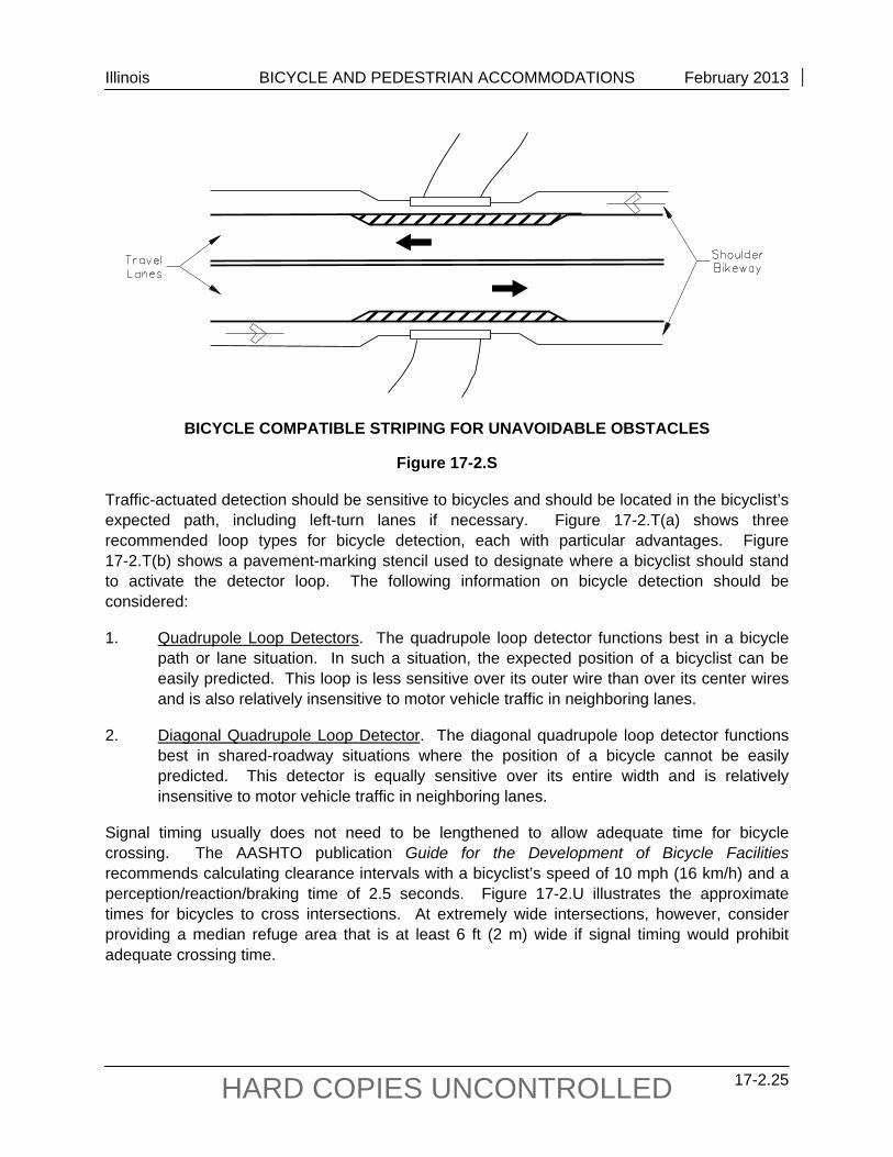
However, short segments of a continuous bike route that do not meet minimum criteria may be marked if the user is adequately warned of the conditions. For example, where a roadway serves as a bikeway and intermittent restrictions on width exist, such as at narrow bridges, mark these obstructions with both signing and pavement markings to warn bicyclists and motorists of the hazards (see Figure 17-2.S).
At signalized intersections where frequent bicyclists need access to a green signal phase, a number of acceptable alternative methods are available including timed signals (where a cyclist must wait for the signal to change), traffic-actuated detectors, and push-button actuation. This opportunity (to access a green signal) should be provided where a marked bikeway crosses the project corridor. Other crossing locations to consider include potential bicycle travel from schools, parks, or other significant destinations described in Section 17-1.04(b).
Illinois BICYCLE AND PEDESTRIAN ACCOMMODATIONS February 2013
17-2.25 HARD COPIES UNCONTROLLED
BICYCLE COMPATIBLE STRIPING FOR UNAVOIDABLE OBSTACLES
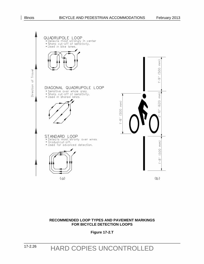
Figure 17-2.S Traffic-actuated detection should be sensitive to bicycles and should be located in the bicyclist’s expected path, including left-turn lanes if necessary. Figure 17-2.T(a) shows three recommended loop types for bicycle detection, each with particular advantages. Figure 17-2.T(b) shows a pavement-marking stencil used to designate where a bicyclist should stand to activate the detector loop. The following information on bicycle detection should be considered:
1. Quadrupole Loop Detectors. The quadrupole loop detector functions best in a bicycle path or lane situation. In such a situation, the expected position of a bicyclist can be easily predicted. This loop is less sensitive over its outer wire than over its center wires and is also relatively insensitive to motor vehicle traffic in neighboring lanes.
2. Diagonal Quadrupole Loop Detector. The diagonal quadrupole loop detector functions best in shared-roadway situations where the position of a bicycle cannot be easily predicted. This detector is equally sensitive over its entire width and is relatively insensitive to motor vehicle traffic in neighboring lanes.
Signal timing usually does not need to be lengthened to allow adequate time for bicycle crossing. The AASHTO publication Guide for the Development of Bicycle Facilities recommends calculating clearance intervals with a bicyclist’s speed of 10 mph (16 km/h) and a perception/reaction/braking time of 2.5 seconds. Figure 17-2.U illustrates the approximate times for bicycles to cross intersections. At extremely wide intersections, however, consider providing a median refuge area that is at least 6 ft (2 m) wide if signal timing would prohibit adequate crossing time.
Illinois BICYCLE AND PEDESTRIAN ACCOMMODATIONS February 2013
17-2.26 HARD COPIES UNCONTROLLED
RECOMMENDED LOOP TYPES AND PAVEMENT MARKINGS FOR BICYCLE DETECTION LOOPS
Figure 17-2.T
Illinois BICYCLE AND PEDESTRIAN ACCOMMODATIONS February 2013
17-2.27 HARD COPIES UNCONTROLLED
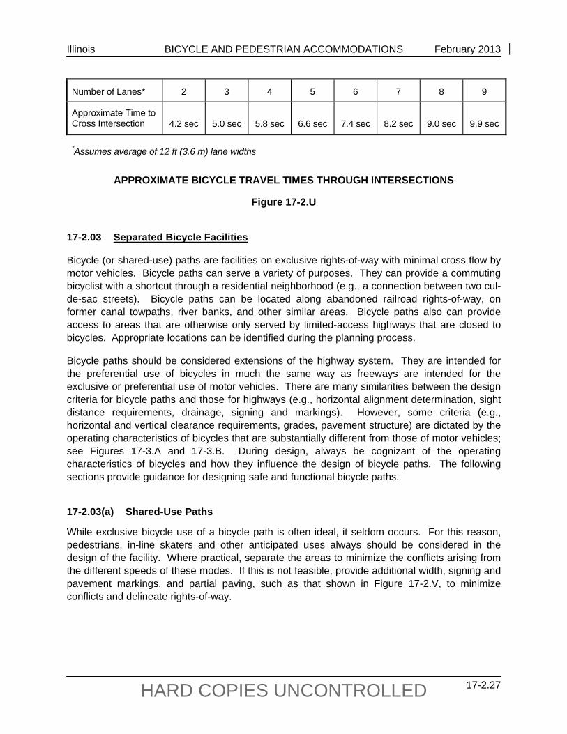
Number of Lanes* 2 3 4 5 6 7 8 9
Approximate Time to Cross Intersection 4.2 sec 5.0 sec 5.8 sec 6.6 sec 7.4 sec 8.2 sec 9.0 sec 9.9 sec
*Assumes average of 12 ft (3.6 m) lane widths
APPROXIMATE BICYCLE TRAVEL TIMES THROUGH INTERSECTIONS
Figure 17-2.U 17-2.03 Separated Bicycle Facilities
Bicycle (or shared-use) paths are facilities on exclusive rights-of-way with minimal cross flow by motor vehicles. Bicycle paths can serve a variety of purposes. They can provide a commuting bicyclist with a shortcut through a residential neighborhood (e.g., a connection between two cul-de-sac streets). Bicycle paths can be located along abandoned railroad rights-of-way, on former canal towpaths, river banks, and other similar areas. Bicycle paths also can provide access to areas that are otherwise only served by limited-access highways that are closed to bicycles. Appropriate locations can be identified during the planning process.
Bicycle paths should be considered extensions of the highway system. They are intended for the preferential use of bicycles in much the same way as freeways are intended for the exclusive or preferential use of motor vehicles. There are many similarities between the design criteria for bicycle paths and those for highways (e.g., horizontal alignment determination, sight distance requirements, drainage, signing and markings). However, some criteria (e.g., horizontal and vertical clearance requirements, grades, pavement structure) are dictated by the operating characteristics of bicycles that are substantially different from those of motor vehicles; see Figures 17-3.A and 17-3.B. During design, always be cognizant of the operating characteristics of bicycles and how they influence the design of bicycle paths. The following sections provide guidance for designing safe and functional bicycle paths.
17-2.03(a) Shared-Use Paths
While exclusive bicycle use of a bicycle path is often ideal, it seldom occurs. For this reason, pedestrians, in-line skaters and other anticipated uses always should be considered in the design of the facility. Where practical, separate the areas to minimize the conflicts arising from the different speeds of these modes. If this is not feasible, provide additional width, signing and pavement markings, and partial paving, such as that shown in Figure 17-2.V, to minimize conflicts and delineate rights-of-way.
Illinois BICYCLE AND PEDESTRIAN ACCOMMODATIONS February 2013
17-2.28 HARD COPIES UNCONTROLLED
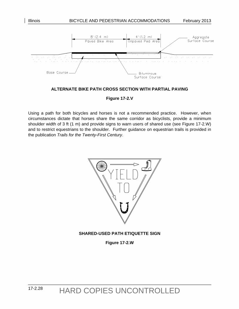
ALTERNATE BIKE PATH CROSS SECTION WITH PARTIAL PAVING
Figure 17-2.V Using a path for both bicycles and horses is not a recommended practice. However, when circumstances dictate that horses share the same corridor as bicyclists, provide a minimum shoulder width of 3 ft (1 m) and provide signs to warn users of shared use (see Figure 17-2.W) and to restrict equestrians to the shoulder. Further guidance on equestrian trails is provided in the publication Trails for the Twenty-First Century.
SHARED-USED PATH ETIQUETTE SIGN
Figure 17-2.W
Illinois BICYCLE AND PEDESTRIAN ACCOMMODATIONS February 2013
17-2.29 HARD COPIES UNCONTROLLED
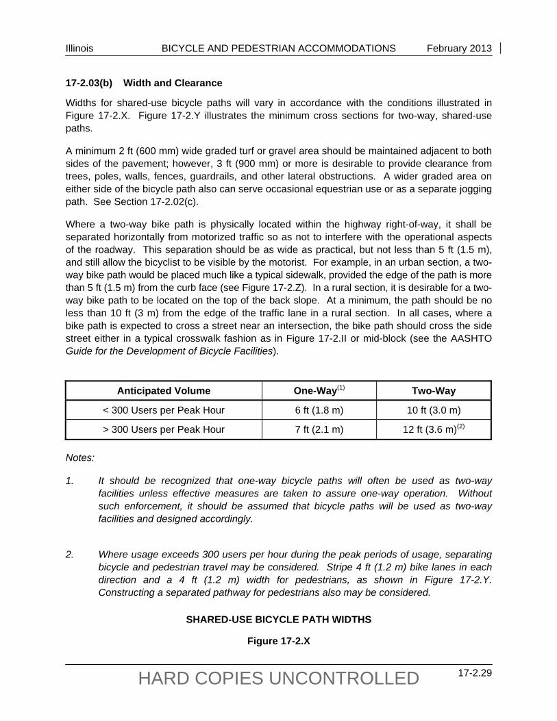
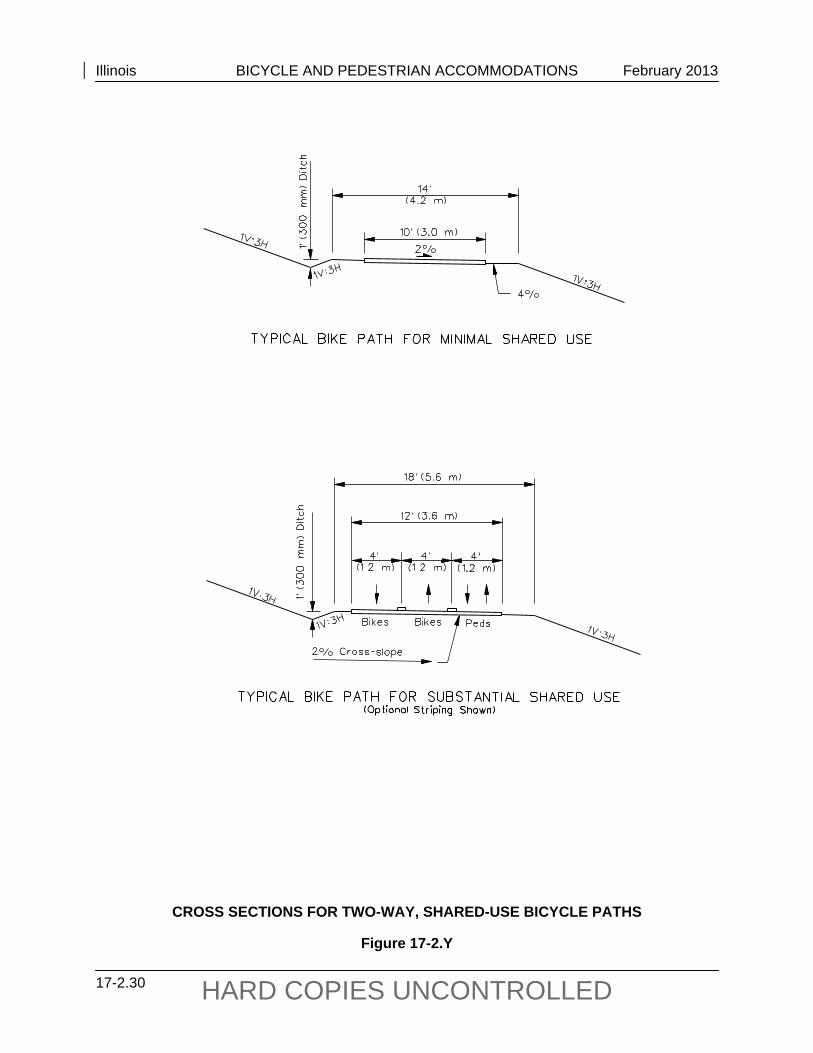
17-2.03(b) Width and Clearance
Widths for shared-use bicycle paths will vary in accordance with the conditions illustrated in Figure 17-2.X. Figure 17-2.Y illustrates the minimum cross sections for two-way, shared-use paths.
A minimum 2 ft (600 mm) wide graded turf or gravel area should be maintained adjacent to both sides of the pavement; however, 3 ft (900 mm) or more is desirable to provide clearance from trees, poles, walls, fences, guardrails, and other lateral obstructions. A wider graded area on either side of the bicycle path also can serve occasional equestrian use or as a separate jogging path. See Section 17-2.02(c).
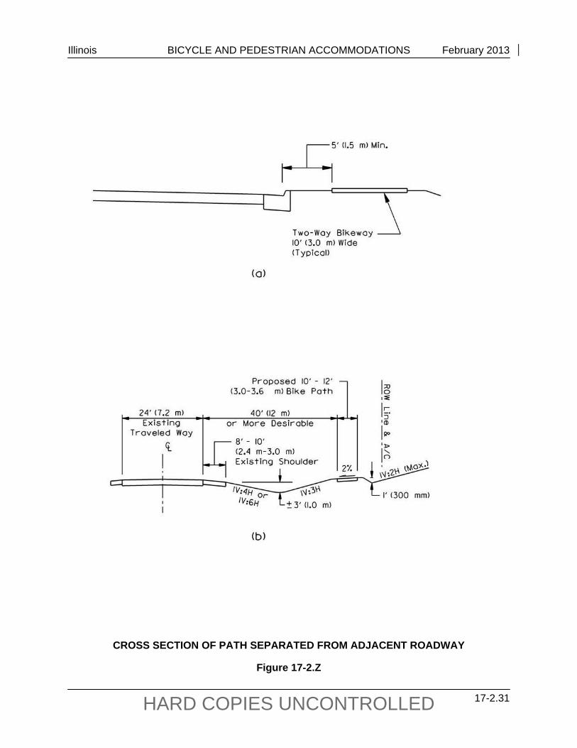
Where a two-way bike path is physically located within the highway right-of-way, it shall be separated horizontally from motorized traffic so as not to interfere with the operational aspects of the roadway. This separation should be as wide as practical, but not less than 5 ft (1.5 m), and still allow the bicyclist to be visible by the motorist. For example, in an urban section, a two-way bike path would be placed much like a typical sidewalk, provided the edge of the path is more than 5 ft (1.5 m) from the curb face (see Figure 17-2.Z). In a rural section, it is desirable for a two-way bike path to be located on the top of the back slope. At a minimum, the path should be no less than 10 ft (3 m) from the edge of the traffic lane in a rural section. In all cases, where a bike path is expected to cross a street near an intersection, the bike path should cross the side street either in a typical crosswalk fashion as in Figure 17-2.II or mid-block (see the AASHTO Guide for the Development of Bicycle Facilities).
Anticipated Volume One-Way(1) Two-Way
< 300 Users per Peak Hour 6 ft (1.8 m) 10 ft (3.0 m)
> 300 Users per Peak Hour 7 ft (2.1 m) 12 ft (3.6 m)(2)
Notes: 1. It should be recognized that one-way bicycle paths will often be used as two-way
facilities unless effective measures are taken to assure one-way operation. Without such enforcement, it should be assumed that bicycle paths will be used as two-way facilities and designed accordingly.
2. Where usage exceeds 300 users per hour during the peak periods of usage, separating
bicycle and pedestrian travel may be considered. Stripe 4 ft (1.2 m) bike lanes in each direction and a 4 ft (1.2 m) width for pedestrians, as shown in Figure 17-2.Y. Constructing a separated pathway for pedestrians also may be considered.
SHARED-USE BICYCLE PATH WIDTHS
Figure 17-2.X
Illinois BICYCLE AND PEDESTRIAN ACCOMMODATIONS February 2013
17-2.30 HARD COPIES UNCONTROLLED
CROSS SECTIONS FOR TWO-WAY, SHARED-USE BICYCLE PATHS
Figure 17-2.Y
Illinois BICYCLE AND PEDESTRIAN ACCOMMODATIONS February 2013
17-2.31 HARD COPIES UNCONTROLLED
CROSS SECTION OF PATH SEPARATED FROM ADJACENT ROADWAY
Figure 17-2.Z

Illinois BICYCLE AND PEDESTRIAN ACCOMMODATIONS February 2013
17-2.32 HARD COPIES UNCONTROLLED
Protect two-way bikeways located less than 5 ft (1.5 m) from the traveled way (generally, the face of the curb) with a 3.5 ft (1.1 m) high barrier. Such barriers serve both to prevent bicyclists from making undesirable movements between the path and the highway shoulder and to reinforce the concept that the bicycle path is an independent facility. For additional information on barriers and railings, see Section 17-2.01(e).
The consideration of safety rails alongside slopes should be based on a subjective analysis of trail-side elements and conditions. Generally, if the consequences of striking a fixed object hazard or running off the path are believed to be more serious than hitting the railing, then the barrier may be warranted. In addition, the cost effectiveness and probability of encroachment also should be considered. For example, along a lengthy tangent section of bicycle path on an elevated railroad section, the cost effectiveness of installing safety rail along the entire distance would be questionable; however, the placement of rail at clearly hazardous locations (e.g., river crossing approaches, less than minimum widths and curves, potential points of conflict) would be prudent. Select the treatment that is judged to be the most practical and cost-effective for the site. The range of treatments includes:
eliminating the hazard (e.g., flatten embankment, remove rock outcroppings); relocating the hazard; shielding the hazard with safety railing; or doing nothing. The determination of the separation distance between a bike path and an active railroad is dependent on the speed and frequency of the rail service, the amount of access available to the railroad from the surrounding area, and the requirements of the railroad company. For low speed and low frequency service, the separation may be as little as 10 ft – 15 ft (3 m – 5 m), with no physical barrier (e.g., fencing, landscaping). As railroad speeds and frequencies increase, the requirements for increased separation and a physical barrier increase as well. An 8 ft (2.4 m) high chain link fence or other barrier type may be required to satisfy the railroad company that bicyclists will be adequately separated from the hazards of the trains.
The vertical clearance to obstructions should be a minimum of 8 ft (2.4 m). However, vertical clearance may need to be greater to permit passage of maintenance vehicles, rescue vehicles, and ambulances. Rescue vehicles typically can exceed 9 ft (2.7 m) in height and 9 ft (2.7 m) in width. In undercrossings and tunnels, a vertical clearance of 10 ft (3 m) is desirable. The geographical location of the vertical obstructions, as well as alternate access points, are primary considerations for determining clearance. It is imperative that adequate clearance be provided where the bikeway offers the primary access to a remote location. Any overhead restrictions with less than a 10 ft (3 m) clearance should be marked on the structure according to the ILMUTCD.
17-2.03(c) Design Speed
Bicycle paths should be designed for a selected speed that is at least as high as the preferred speed of the faster bicyclists. In general, use a minimum design speed of 20 mph (30 km/h).
Illinois BICYCLE AND PEDESTRIAN ACCOMMODATIONS February 2013
17-2.33 HARD COPIES UNCONTROLLED
However, where the grade exceeds 4% or where strong prevailing tail winds exist, (e.g., along a lake or river), a design speed of 30 mph (50 km/h) is advisable.
On unpaved paths, where bicyclists tend to ride slower, use a lower design speed of 15 mph (25 km/h). Similarly, where the grades or the prevailing winds dictate, a higher design speed of 25 mph (40 km/h) should be considered.
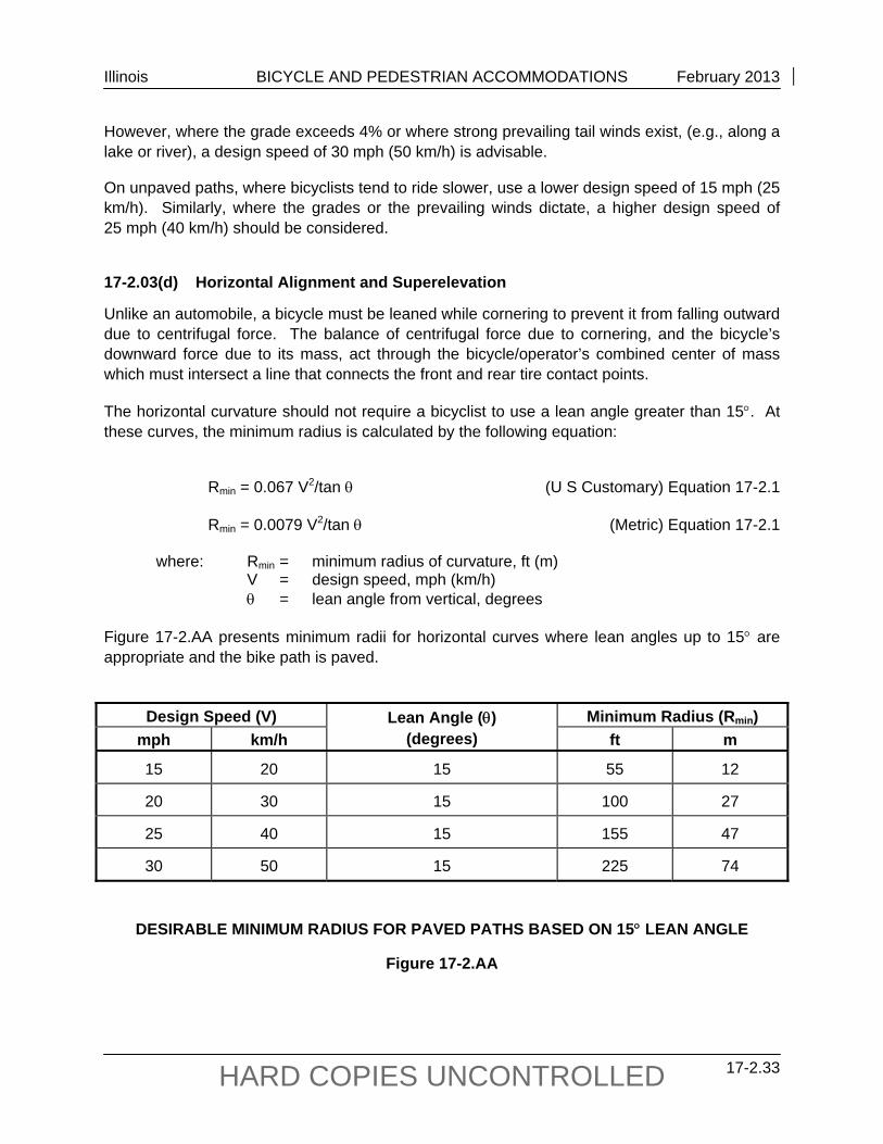
17-2.03(d) Horizontal Alignment and Superelevation
Unlike an automobile, a bicycle must be leaned while cornering to prevent it from falling outward due to centrifugal force. The balance of centrifugal force due to cornering, and the bicycle’s downward force due to its mass, act through the bicycle/operator’s combined center of mass which must intersect a line that connects the front and rear tire contact points.
The horizontal curvature should not require a bicyclist to use a lean angle greater than 15. At these curves, the minimum radius is calculated by the following equation:
Rmin = 0.067 V2/tan (U S Customary) Equation 17-2.1
Rmin = 0.0079 V2/tan (Metric) Equation 17-2.1
where: Rmin = minimum radius of curvature, ft (m)
V = design speed, mph (km/h) = lean angle from vertical, degrees Figure 17-2.AA presents minimum radii for horizontal curves where lean angles up to 15 are appropriate and the bike path is paved.
Design Speed (V) Lean Angle ()
(degrees) Minimum Radius (Rmin)
mph km/h ft m
15 20 15 55 12
20 30 15 100 27
25 40 15 155 47
30 50 15 225 74
DESIRABLE MINIMUM RADIUS FOR PAVED PATHS BASED ON 15 LEAN ANGLE
Figure 17-2.AA
Illinois BICYCLE AND PEDESTRIAN ACCOMMODATIONS February 2013
17-2.34 HARD COPIES UNCONTROLLED
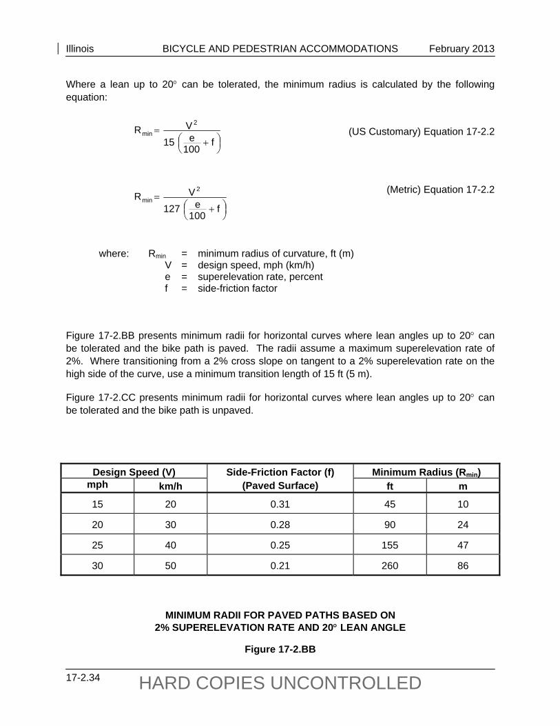
Where a lean up to 20 can be tolerated, the minimum radius is calculated by the following equation:
(US Customary) Equation 17-2.2
(Metric) Equation 17-2.2
where: Rmin = minimum radius of curvature, ft (m) V = design speed, mph (km/h)
e = superelevation rate, percent f = side-friction factor Figure 17-2.BB presents minimum radii for horizontal curves where lean angles up to 20 can be tolerated and the bike path is paved. The radii assume a maximum superelevation rate of 2%. Where transitioning from a 2% cross slope on tangent to a 2% superelevation rate on the high side of the curve, use a minimum transition length of 15 ft (5 m).
Figure 17-2.CC presents minimum radii for horizontal curves where lean angles up to 20 can be tolerated and the bike path is unpaved.
Design Speed (V) Side-Friction Factor (f) (Paved Surface)
Minimum Radius (Rmin) mph km/h ft m
15 20 0.31 45 10
20 30 0.28 90 24
25 40 0.25 155 47
30 50 0.21 260 86
MINIMUM RADII FOR PAVED PATHS BASED ON 2% SUPERELEVATION RATE AND 20 LEAN ANGLE
Figure 17-2.BB
f
100e15
VR2
min
f
100e127
VR2
min
Illinois BICYCLE AND PEDESTRIAN ACCOMMODATIONS February 2013
17-2.35 HARD COPIES UNCONTROLLED
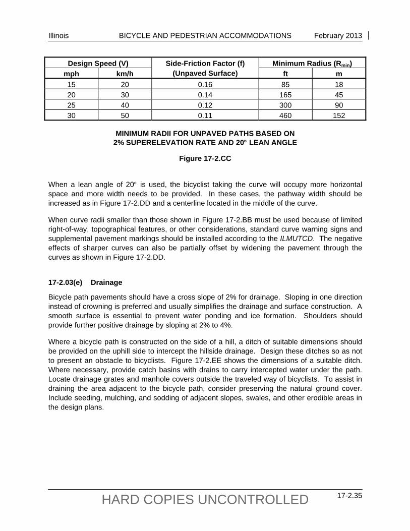
Design Speed (V) Side-Friction Factor (f) (Unpaved Surface)
Minimum Radius (Rmin) mph km/h ft m 15 20 0.16 85 18 20 30 0.14 165 45 25 40 0.12 300 90 30 50 0.11 460 152
MINIMUM RADII FOR UNPAVED PATHS BASED ON
2% SUPERELEVATION RATE AND 20 LEAN ANGLE
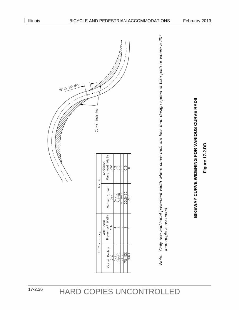
Figure 17-2.CC When a lean angle of 20 is used, the bicyclist taking the curve will occupy more horizontal space and more width needs to be provided. In these cases, the pathway width should be increased as in Figure 17-2.DD and a centerline located in the middle of the curve.
When curve radii smaller than those shown in Figure 17-2.BB must be used because of limited right-of-way, topographical features, or other considerations, standard curve warning signs and supplemental pavement markings should be installed according to the ILMUTCD. The negative effects of sharper curves can also be partially offset by widening the pavement through the curves as shown in Figure 17-2.DD.
17-2.03(e) Drainage
Bicycle path pavements should have a cross slope of 2% for drainage. Sloping in one direction instead of crowning is preferred and usually simplifies the drainage and surface construction. A smooth surface is essential to prevent water ponding and ice formation. Shoulders should provide further positive drainage by sloping at 2% to 4%.
Where a bicycle path is constructed on the side of a hill, a ditch of suitable dimensions should be provided on the uphill side to intercept the hillside drainage. Design these ditches so as not to present an obstacle to bicyclists. Figure 17-2.EE shows the dimensions of a suitable ditch. Where necessary, provide catch basins with drains to carry intercepted water under the path. Locate drainage grates and manhole covers outside the traveled way of bicyclists. To assist in draining the area adjacent to the bicycle path, consider preserving the natural ground cover. Include seeding, mulching, and sodding of adjacent slopes, swales, and other erodible areas in the design plans.
Illinois BICYCLE AND PEDESTRIAN ACCOMMODATIONS February 2013
17-2.36 HARD COPIES UNCONTROLLED
Not
e:
Onl
y us
e ad
ditio
nal p
avem
ent w
idth
whe
re c
urve
rad
ii ar
e le
ss th
an d
esig
n sp
eed
of b
ike
path
or
whe
re a
20
le
an a
ngle
is a
ssum
ed.
BIK
EWA
Y C
UR
VE W
IDEN
ING
FO
R V
AR
IOU
S C
UR
VE R
AD
II
Figu
re 1
7-2.
DD
Illinois BICYCLE AND PEDESTRIAN ACCOMMODATIONS February 2013
17-2.37 HARD COPIES UNCONTROLLED
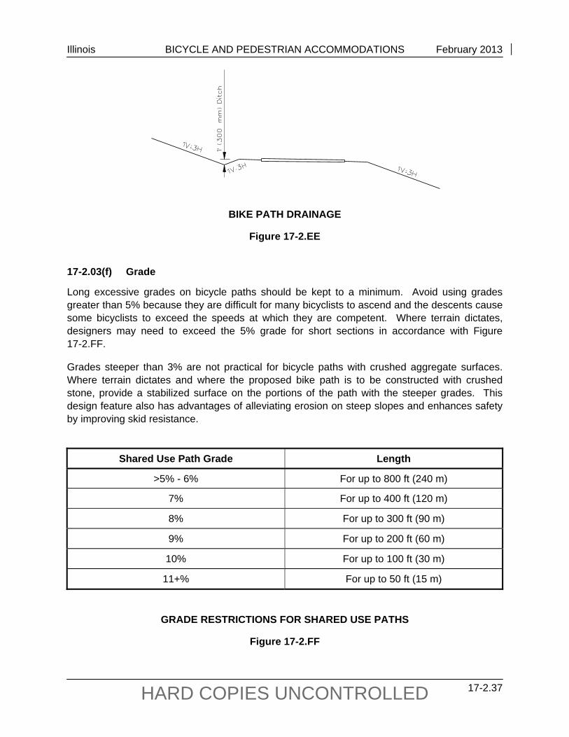
BIKE PATH DRAINAGE
Figure 17-2.EE 17-2.03(f) Grade
Long excessive grades on bicycle paths should be kept to a minimum. Avoid using grades greater than 5% because they are difficult for many bicyclists to ascend and the descents cause some bicyclists to exceed the speeds at which they are competent. Where terrain dictates, designers may need to exceed the 5% grade for short sections in accordance with Figure 17-2.FF.
Grades steeper than 3% are not practical for bicycle paths with crushed aggregate surfaces. Where terrain dictates and where the proposed bike path is to be constructed with crushed stone, provide a stabilized surface on the portions of the path with the steeper grades. This design feature also has advantages of alleviating erosion on steep slopes and enhances safety by improving skid resistance.
Shared Use Path Grade Length
>5% - 6% For up to 800 ft (240 m)
7% For up to 400 ft (120 m)
8% For up to 300 ft (90 m)
9% For up to 200 ft (60 m)
10% For up to 100 ft (30 m)
11+% For up to 50 ft (15 m)
GRADE RESTRICTIONS FOR SHARED USE PATHS
Figure 17-2.FF
Illinois BICYCLE AND PEDESTRIAN ACCOMMODATIONS February 2013
17-2.38 HARD COPIES UNCONTROLLED
Options to mitigate problems caused by excessive grades are as follows:
When using a long grade, provide an additional 4 ft to 6 ft (1.2 m to 1.8 m) of width to permit slower speed bicyclists to dismount and walk their bikes up the grade.
Provide signing to alert bicyclists of the maximum percent of grade.
Provide recommended descent speed signing.
Exceed minimum stopping sight distances and provide longer radius curves.
17-2.03(g) Accessibility
The vast majority of independent bicycle paths in Illinois are located on abandoned railroads, which were originally located and constructed where changes in elevation and, thus, grades could be minimized. Many miles (kilometers) of paths have been fashioned from canal towpaths. These grades are ideal for meeting the needs of all users, including disabled users. Logically located access points to these paths also should ensure a disabled person’s ability to access and use these facilities. Paths will exist, however, that will be impractical or environmentally inappropriate to provide access for the disabled. The conditions that would prevent full accessibility include those that:
Cause harm to significant natural, cultural, historic or religious characteristics of a site;
Alter the fundamental experience of the setting or intended purpose of the trail;
Require construction methods that are prohibited by federal, state or local regulations; and
Involve terrain characteristics (e.g., slope, soils, geologic or aquatic) that prevent compliance with the technical provisions (being developed by the Regulatory Negotiation Committee on Outdoor Developed Areas).
Available funding for the project is insufficient grounds for not meeting ADA requirements. The ADA Access Board’s publication Recommendations for Accessibility Guidelines: Recreational Facilities and Outdoor Developed Areas suggests that paths be assessed according to their “challenge level.” Locate major path heads and access points and their associated facilities near areas that are available to all users, so that the facility may be enjoyed by as many users as possible. Thus, path heads and access points should be accessible to all users. However, because areas of the path may not be accessible to all users, the challenge level of each facility should be posted for the utility of all disabled users.
Outdoor linear bikeways/paths are classified based on the level of development of the surrounding area. A “Highly” developed area would be represented by a bikeway/path running through an urbanized area, such as a downtown area or a college campus. A “Moderately” developed area might be a path located along a river or canal in a semi-urbanized area. A
Illinois BICYCLE AND PEDESTRIAN ACCOMMODATIONS February 2013
17-2.39 HARD COPIES UNCONTROLLED
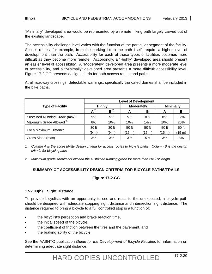
“Minimally” developed area would be represented by a remote hiking path largely carved out of the existing landscape.
The accessibility challenge level varies with the function of the particular segment of the facility. Access routes, for example, from the parking lot to the path itself, require a higher level of development than the path. Accessibility for each of these types of facilities becomes more difficult as they become more remote. Accordingly, a “Highly” developed area should present an easier level of accessibility. A “Moderately” developed area presents a more moderate level of accessibility, and a “Minimally” developed area presents a more difficult accessibility level. Figure 17-2.GG presents design criteria for both access routes and paths.
At all roadway crossings, detectable warnings, specifically truncated domes shall be included in the bike paths.
Level of Development
Type of Facility Highly Moderately Minimally A(1) B(1) A B A B Sustained Running Grade (max) 5% 5% 5% 8% 8% 12% Maximum Grade Allowed(2) 8% 10% 10% 14% 10% 20%
For a Maximum Distance 30 ft (9 m)
30 ft (9 m)
50 ft (15 m)
50 ft (15 m)
50 ft (15 m)
50 ft (15 m)
Cross Slope (max) 3% 3% 3% 5% 3% 8% 1. Column A is the accessibility design criteria for access routes to bicycle paths. Column B is the design
criteria for bicycle paths. 2. Maximum grade should not exceed the sustained running grade for more than 20% of length.
SUMMARY OF ACCESSIBILITY DESIGN CRITERIA FOR BICYCLE PATHS/TRAILS
Figure 17-2.GG 17-2.03(h) Sight Distance
To provide bicyclists with an opportunity to see and react to the unexpected, a bicycle path should be designed with adequate stopping sight distance and intersection sight distance. The distance required to bring a bicycle to a full controlled stop is a function of:
the bicyclist’s perception and brake reaction time, the initial speed of the bicycle, the coefficient of friction between the tires and the pavement, and the braking ability of the bicycle. See the AASHTO publication Guide for the Development of Bicycle Facilities for information on determining adequate sight distance.
Illinois BICYCLE AND PEDESTRIAN ACCOMMODATIONS February 2013
17-2.40 HARD COPIES UNCONTROLLED
Bicyclists frequently ride abreast of each other on bicycle paths and, on narrow bicycle paths, bicyclists have a tendency to ride near the middle of the path. For these reasons, and because of the serious consequences of a head-on bicycle crash, calculate lateral clearances on horizontal curves based on the sum of the stopping sight distances for bicyclists traveling in opposite directions around the curve. Where this is not feasible, consider widening the path through the curve, installing a yellow center stripe, installing turn or curve signs (W1-1 or W1-2) as appropriate, or “REDUCE SPEED” sign, or some combination of these alternatives.
17-2.03(i) Bike Path Intersections
Very few bikeways start and end at a trail head without crossing various transportation elements in between. These intersections can be roadways, railroads, or other bike paths. These points of intersection present potential conflicts and must be thoroughly analyzed to consider their impacts on the trail user as well as the user of the other intersecting legs. Figure 17-2.HH illustrates how a bikeway could interact with a variety of intersections. All bike paths entering a public right-of-way requires the installation of truncated domes on the path.
Roadway Intersections Intersections with roadways are important considerations in bicycle path design. It is important to understand that the majority of bicycle travel on pathways is not from endpoint to endpoint and that cyclists will use the roadway system as access and egress to the path. It is therefore imperative to ensure safe and reasonable points of access to and from roadways along the length of the bike path.
According to AASHTO, it is preferable that the crossing of a bicycle path and a highway be at a location significantly away from the influence of intersections with other highways. Controlling vehicular movements at such remote intersections is more easily and safely accomplished through the application of standard traffic control devices and normal rules of the road.
Where physical constraints prohibit such independent intersections, the crossing may be at or adjacent to a pedestrian crossing, as shown in Figure 17-2.II. These joint crossings should meet the requirements of Figure 17-2.X where possible to accommodate dual use. However, any use of rerouting that causes redundant travel may be perceived as a barrier and should not be used. Use engineering judgment to decide when such safety measures are necessary and cost effective by considering traffic volumes, motor vehicle speeds, and anticipated usage. Assign right-of-way and provide adequate sight distance to minimize the potential for conflicts resulting from unconventional turning movements.
Where bike paths cross roadways, assess the safety potential of the crossings. Evaluate the crossing according to the minimum pedestrian volume and school crossing control criteria provided in the ILMUTCD and the ITE publication School Trip Safety Program Guidelines. This guidance indicates that adequate gaps need to occur on an average of at least one per minute during times of predominate usage. If adequate gaps are not available, some form of crossing
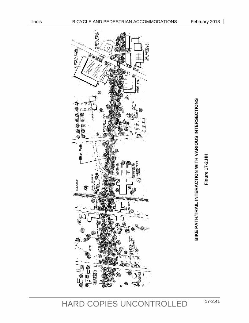
Illinois BICYCLE AND PEDESTRIAN ACCOMMODATIONS February 2013
17-2.41 HARD COPIES UNCONTROLLED
BIK
E PA
TH/T
RA
IL IN
TER
AC
TIO
N W
ITH
VA
RIO
US
INTE
RSE
CTI
ON
S
Figu
re 1
7-2.
HH
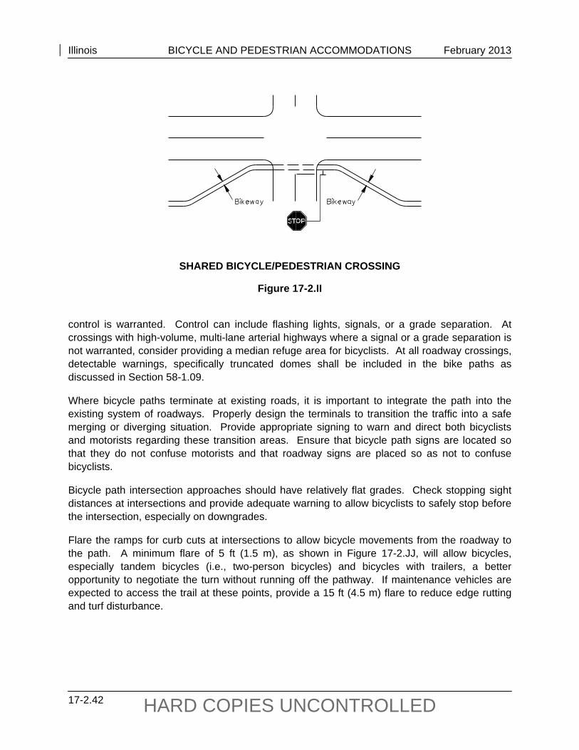
Illinois BICYCLE AND PEDESTRIAN ACCOMMODATIONS February 2013
17-2.42 HARD COPIES UNCONTROLLED
SHARED BICYCLE/PEDESTRIAN CROSSING
Figure 17-2.II control is warranted. Control can include flashing lights, signals, or a grade separation. At crossings with high-volume, multi-lane arterial highways where a signal or a grade separation is not warranted, consider providing a median refuge area for bicyclists. At all roadway crossings, detectable warnings, specifically truncated domes shall be included in the bike paths as discussed in Section 58-1.09.
Where bicycle paths terminate at existing roads, it is important to integrate the path into the existing system of roadways. Properly design the terminals to transition the traffic into a safe merging or diverging situation. Provide appropriate signing to warn and direct both bicyclists and motorists regarding these transition areas. Ensure that bicycle path signs are located so that they do not confuse motorists and that roadway signs are placed so as not to confuse bicyclists.
Bicycle path intersection approaches should have relatively flat grades. Check stopping sight distances at intersections and provide adequate warning to allow bicyclists to safely stop before the intersection, especially on downgrades.
Flare the ramps for curb cuts at intersections to allow bicycle movements from the roadway to the path. A minimum flare of 5 ft (1.5 m), as shown in Figure 17-2.JJ, will allow bicycles, especially tandem bicycles (i.e., two-person bicycles) and bicycles with trailers, a better opportunity to negotiate the turn without running off the pathway. If maintenance vehicles are expected to access the trail at these points, provide a 15 ft (4.5 m) flare to reduce edge rutting and turf disturbance.
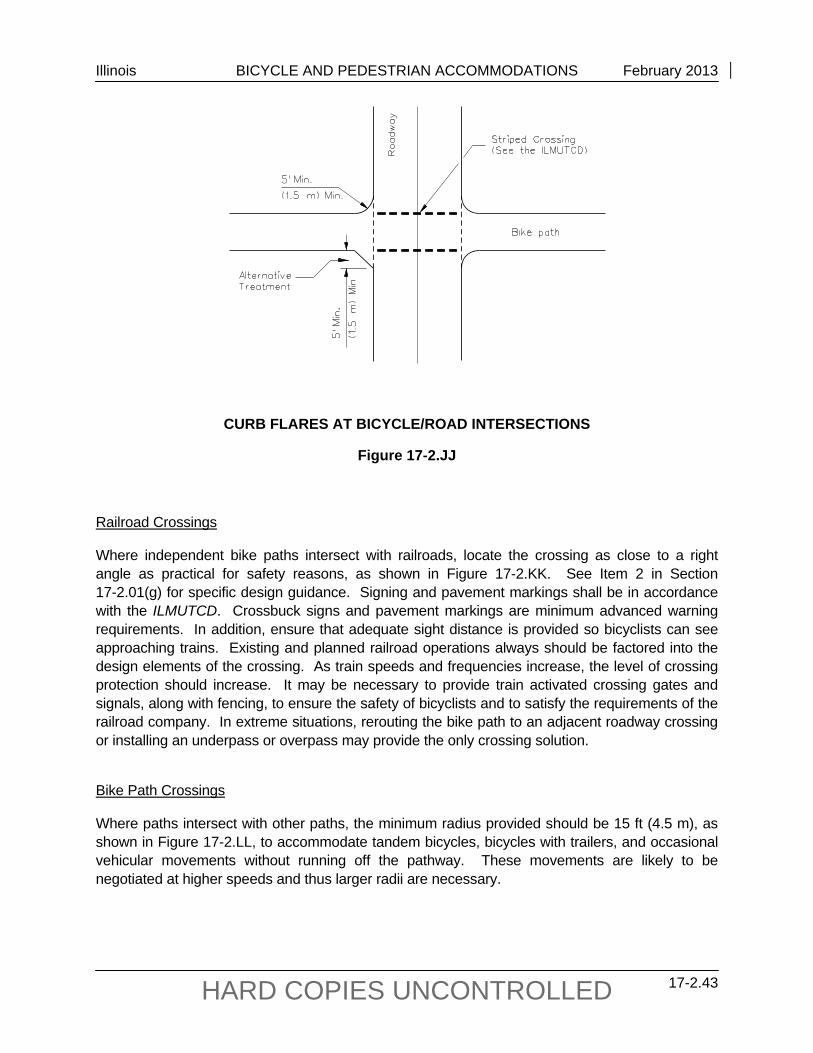
Illinois BICYCLE AND PEDESTRIAN ACCOMMODATIONS February 2013
17-2.43 HARD COPIES UNCONTROLLED
CURB FLARES AT BICYCLE/ROAD INTERSECTIONS
Figure 17-2.JJ
Railroad Crossings
Where independent bike paths intersect with railroads, locate the crossing as close to a right angle as practical for safety reasons, as shown in Figure 17-2.KK. See Item 2 in Section 17-2.01(g) for specific design guidance. Signing and pavement markings shall be in accordance with the ILMUTCD. Crossbuck signs and pavement markings are minimum advanced warning requirements. In addition, ensure that adequate sight distance is provided so bicyclists can see approaching trains. Existing and planned railroad operations always should be factored into the design elements of the crossing. As train speeds and frequencies increase, the level of crossing protection should increase. It may be necessary to provide train activated crossing gates and signals, along with fencing, to ensure the safety of bicyclists and to satisfy the requirements of the railroad company. In extreme situations, rerouting the bike path to an adjacent roadway crossing or installing an underpass or overpass may provide the only crossing solution.
Bike Path Crossings
Where paths intersect with other paths, the minimum radius provided should be 15 ft (4.5 m), as shown in Figure 17-2.LL, to accommodate tandem bicycles, bicycles with trailers, and occasional vehicular movements without running off the pathway. These movements are likely to be negotiated at higher speeds and thus larger radii are necessary.
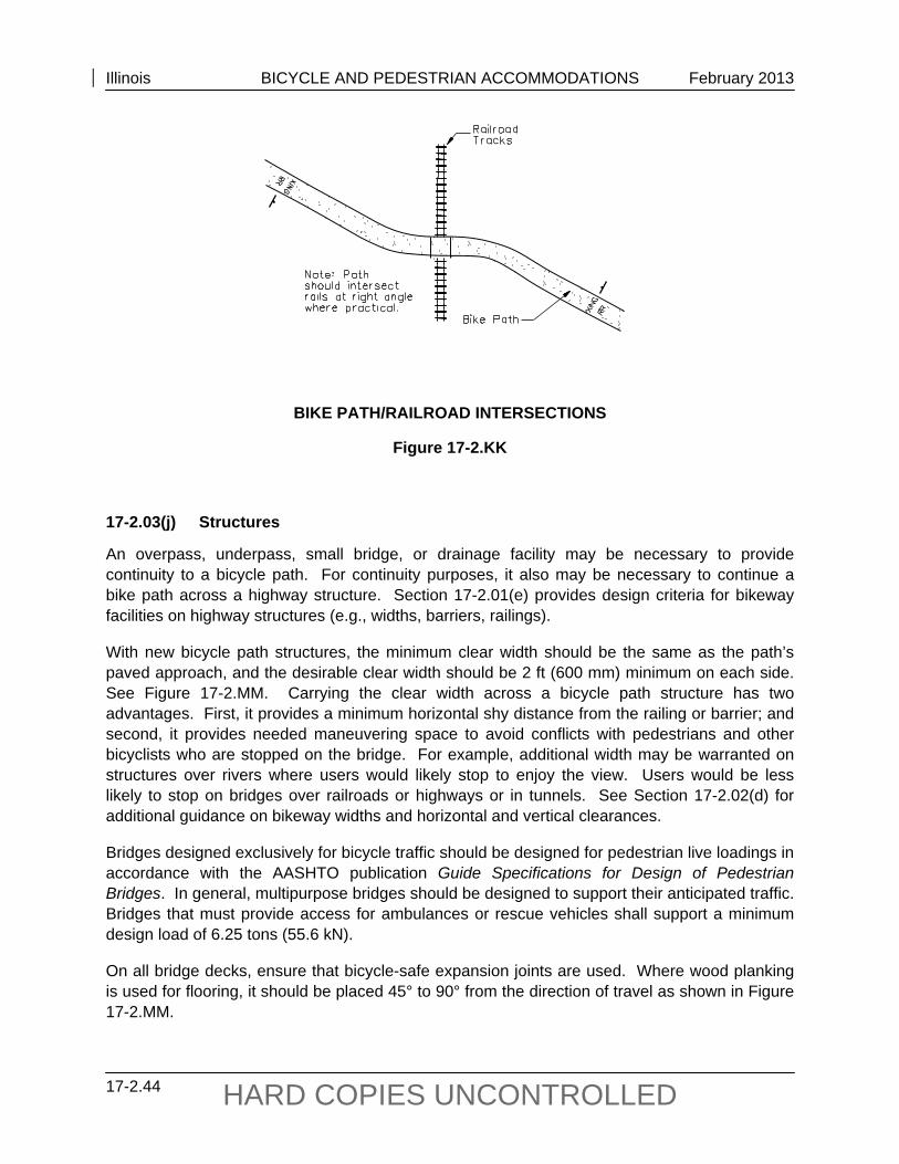
Illinois BICYCLE AND PEDESTRIAN ACCOMMODATIONS February 2013
17-2.44 HARD COPIES UNCONTROLLED
BIKE PATH/RAILROAD INTERSECTIONS
Figure 17-2.KK 17-2.03(j) Structures
An overpass, underpass, small bridge, or drainage facility may be necessary to provide continuity to a bicycle path. For continuity purposes, it also may be necessary to continue a bike path across a highway structure. Section 17-2.01(e) provides design criteria for bikeway facilities on highway structures (e.g., widths, barriers, railings).
With new bicycle path structures, the minimum clear width should be the same as the path’s paved approach, and the desirable clear width should be 2 ft (600 mm) minimum on each side. See Figure 17-2.MM. Carrying the clear width across a bicycle path structure has two advantages. First, it provides a minimum horizontal shy distance from the railing or barrier; and second, it provides needed maneuvering space to avoid conflicts with pedestrians and other bicyclists who are stopped on the bridge. For example, additional width may be warranted on structures over rivers where users would likely stop to enjoy the view. Users would be less likely to stop on bridges over railroads or highways or in tunnels. See Section 17-2.02(d) for additional guidance on bikeway widths and horizontal and vertical clearances.
Bridges designed exclusively for bicycle traffic should be designed for pedestrian live loadings in accordance with the AASHTO publication Guide Specifications for Design of Pedestrian Bridges. In general, multipurpose bridges should be designed to support their anticipated traffic. Bridges that must provide access for ambulances or rescue vehicles shall support a minimum design load of 6.25 tons (55.6 kN).
On all bridge decks, ensure that bicycle-safe expansion joints are used. Where wood planking is used for flooring, it should be placed 45° to 90° from the direction of travel as shown in Figure 17-2.MM.
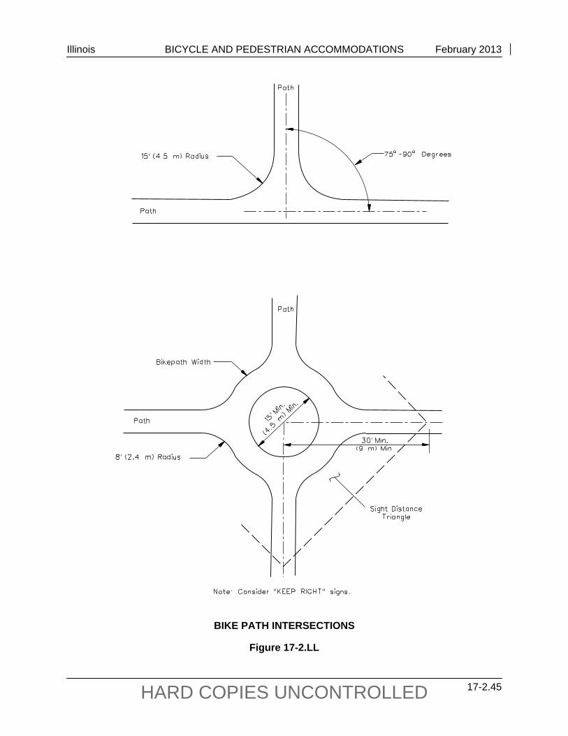
Illinois BICYCLE AND PEDESTRIAN ACCOMMODATIONS February 2013
17-2.45 HARD COPIES UNCONTROLLED
BIKE PATH INTERSECTIONS
Figure 17-2.LL
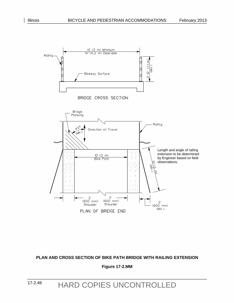
Illinois BICYCLE AND PEDESTRIAN ACCOMMODATIONS February 2013
17-2.46 HARD COPIES UNCONTROLLED
PLAN AND CROSS SECTION OF BIKE PATH BRIDGE WITH RAILING EXTENSION
Figure 17-2.MM
Length and angle of railing extension to be determined by Engineer based on field observations.
Illinois BICYCLE AND PEDESTRIAN ACCOMMODATIONS February 2013
17-2.47 HARD COPIES UNCONTROLLED
Bridge railings on paths should be a minimum of 3.5 ft (1.1 m) tall. Bridge approaches should provide a safety railing as shown in Figure 17-2.MM to protect users from hazardous conditions.
Certainly, other types of bikeway structures will be necessitated by the various ways that bikeways can interface with roadways, rivers, or railroads. Bikeways can utilize the underside of a highway or railroad bridge. Bikeways can cross under roadways or railroads in various ways, as illustrated in Figures 17-2.N, 17-2.NN, and 17-2.OO.
Bridge deck replacement or rehabilitation projects are not intended to widen the traveled way but rather improve the roadway surface on the structure. Bridge width is limited to the existing components of the substructure and as such may not allow the bicycle accommodations called for in the Facility Selection Table, Figure 17-2.A. However, those structures should be reviewed and widened as much as safety will allow. For the purposes of this policy, culverts are not considered structures as they can be extended to meet future needs. For any improvement that includes existing or new culverts, those culverts shall be extended to accommodate the bicycle accommodation, if bicycle warrants are met. If no warrants are met then no accommodation is required.
Design of bikeway tunnels should follow the same guidance for size and overhead clearance, as discussed in Section 17-2.02(d), with recognition of the types of traffic that need to be accommodated (e.g., emergency vehicles). With tunnels or box culverts exceeding 100 ft (30 m) in length, the users’ sense of security is enhanced with larger openings (minimum 10 ft (3 m) high and 14 ft (4.2 m) wide). The alignment of the approaching path should provide a clear view through the structure where practical. On long structures (e.g., under multi-lane highways) a shaft opening at the median can provide natural light and ventilation. Lighting should be considered in areas where security is a concern (see Section 17-2.02(n)). Where bikeways are routed under highway bridges, drainage from the bridge above should be routed to drain away from the path surface.
In limited, restricted cases, bicycle access sometimes can be provided under roadways or railroads through pedestrian underpasses. While not ideal because a bicyclist may need to dismount and act as a pedestrian, these underpasses sometimes offer a safer alternative than an at-grade crossing. Where bicyclists are required to walk their bicycles up stairs, provide ramps at the outer edge to facilitate ease of access and egress as shown in Figure 17-2.PP.
In areas where water flow is intermittent and minimal, paved fords may be a reasonable option to a bridge.
17-2.03(k) Signing and Marking
Adequate signing and marking are essential on bicycle paths, especially to alert bicyclists to potential conflicts and to convey regulatory messages to both bicyclists and motorists at highway intersections. Provide warning signs for design elements that are less than minimum criteria (e.g., less than minimum curve radii, vertical or horizontal clearances, speeds dictated by grades) to warn the user of these conditions. In addition, use guide signing, (e.g., directions, destinations, distances, route numbers, names of crossing streets) in the same manner as they
Illinois BICYCLE AND PEDESTRIAN ACCOMMODATIONS February 2013
17-2.48 HARD COPIES UNCONTROLLED
are used on highways. In general, uniform application of traffic control devices, as described in the ILMUTCD, will tend to encourage proper bicyclist, as well as motorist, behavior.
Consider a broken yellow centerline stripe (3 ft (1 m) stripe with 10 ft (3 m) gap) to separate opposite directions of travel. This is particularly beneficial in the following circumstances:
for heavy volumes of bicycles, on curves with restricted sight distance, and on unlighted paths where nighttime riding is expected.
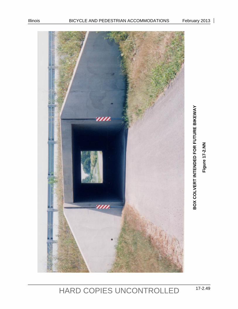
Illinois BICYCLE AND PEDESTRIAN ACCOMMODATIONS February 2013
17-2.49 HARD COPIES UNCONTROLLED
BO
X C
OLV
ERT
INTE
ND
ED F
OR
FU
TUR
E B
IKEW
AY
Figu
re 1
7-2.
NN
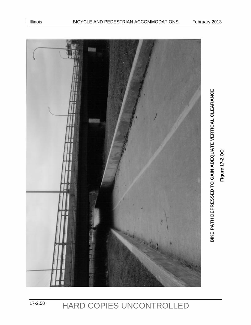
Illinois BICYCLE AND PEDESTRIAN ACCOMMODATIONS February 2013
17-2.50 HARD COPIES UNCONTROLLED
BIK
E PA
TH D
EPR
ESSE
D T
O G
AIN
AD
EQU
ATE
VER
TIC
AL
CLE
AR
AN
CE
Figu
re 1
7-2.
OO
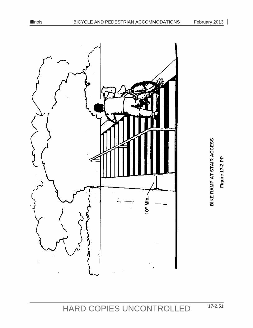
Illinois BICYCLE AND PEDESTRIAN ACCOMMODATIONS February 2013
17-2.51 HARD COPIES UNCONTROLLED
BIK
E R
AM
P A
T ST
AIR
AC
CES
S
Figu
re 1
7-2.
PP
Illinois BICYCLE AND PEDESTRIAN ACCOMMODATIONS February 2013
17-2.52 HARD COPIES UNCONTROLLED
White edge lines also can be very beneficial where nighttime bicycle traffic is expected. Marking should be considered for shared-use paths that are 13 ft (4 m) or wider to delineate lanes for bicyclists and pedestrians, as shown in Figure 17-2.Y.
Care should be exercised in the choice of pavement marking materials. Some marking materials are slippery when wet and should be avoided in favor of more skid resistant materials.
17-2.03(l) Lighting
Fixed-source lighting reduces conflicts along paths and at intersections. In addition, lighting allows the bicyclist to see the bicycle path direction, surface conditions, and obstacles. Lighting for bicycle paths is important and should be considered where riding at night is expected (e.g., bicycle paths serving college students or commuters, highway intersections). Lighting also should be considered through underpasses or tunnels and when nighttime security could be a problem (see Chapter 56). Depending on the location, average maintained horizontal illumination levels of 5 lx to 22 lx should be considered. Where special security problems exist, higher illumination levels may be considered. Light standards (poles) should meet the recommended horizontal and vertical clearances. Luminaires and standards should be at a scale appropriate for a pedestrian or bicycle path. Where security is a problem, lighting fixtures should be vandal proof.
17-2.03(m) Restriction of Motor Vehicle Traffic
Existing bicycle paths may need some form of physical barrier at roadway intersections to prevent unauthorized motor vehicles from using the facilities. However, caution of barrier placement is advised. Due to safety concerns of barrier collisions, consideration should not be automatic in proposed trails and only used in areas where unauthorized use is likely or known to exist. Provisions can be made for a lockable, removable post (“bollard”) or drop gate to permit entrance by authorized vehicles. The posts should be set far enough back from the edge of the vehicular roadway so as not to constitute a hazard. They shall meet Federal breakaway sign post criteria where susceptible to being struck by vehicles. Where necessary, the post should be permanently reflectorized for nighttime visibility and painted a bright color for improved daytime visibility. When more than one post is used, 5 ft (1.5 m) spacing is recommended, as indicated in Figure 17-2.QQ. Do not use gates that prohibit entry by persons in wheelchairs, cause bicyclists to enter the path around the outside of the gate post, or restrict the movement of any intended users.
An alternative method of restricting entry of motor vehicles is to split the entry way into two 5 ft (1.5 m) sections separated by low landscaping as shown in Figure 17-2.RR. Emergency vehicles can enter, if necessary, by straddling the landscaping. The higher maintenance costs associated with landscaping should be acknowledged, however, before this alternative method is selected.
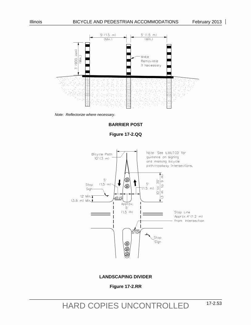
Illinois BICYCLE AND PEDESTRIAN ACCOMMODATIONS February 2013
17-2.53 HARD COPIES UNCONTROLLED
Note: Reflectorize where necessary.
BARRIER POST
Figure 17-2.QQ
LANDSCAPING DIVIDER
Figure 17-2.RR
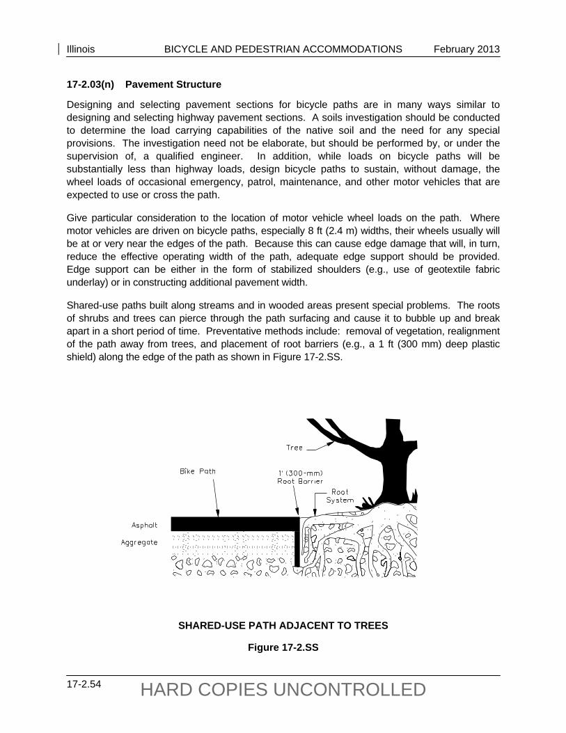
Illinois BICYCLE AND PEDESTRIAN ACCOMMODATIONS February 2013
17-2.54 HARD COPIES UNCONTROLLED
17-2.03(n) Pavement Structure
Designing and selecting pavement sections for bicycle paths are in many ways similar to designing and selecting highway pavement sections. A soils investigation should be conducted to determine the load carrying capabilities of the native soil and the need for any special provisions. The investigation need not be elaborate, but should be performed by, or under the supervision of, a qualified engineer. In addition, while loads on bicycle paths will be substantially less than highway loads, design bicycle paths to sustain, without damage, the wheel loads of occasional emergency, patrol, maintenance, and other motor vehicles that are expected to use or cross the path.
Give particular consideration to the location of motor vehicle wheel loads on the path. Where motor vehicles are driven on bicycle paths, especially 8 ft (2.4 m) widths, their wheels usually will be at or very near the edges of the path. Because this can cause edge damage that will, in turn, reduce the effective operating width of the path, adequate edge support should be provided. Edge support can be either in the form of stabilized shoulders (e.g., use of geotextile fabric underlay) or in constructing additional pavement width.
Shared-use paths built along streams and in wooded areas present special problems. The roots of shrubs and trees can pierce through the path surfacing and cause it to bubble up and break apart in a short period of time. Preventative methods include: removal of vegetation, realignment of the path away from trees, and placement of root barriers (e.g., a 1 ft (300 mm) deep plastic shield) along the edge of the path as shown in Figure 17-2.SS.
SHARED-USE PATH ADJACENT TO TREES
Figure 17-2.SS
Illinois BICYCLE AND PEDESTRIAN ACCOMMODATIONS February 2013
17-2.55 HARD COPIES UNCONTROLLED
At unpaved highway or driveway crossings of bicycle paths, pave the highway or driveway a minimum of 10 ft (3 m) on each side of the crossing to reduce the amount of gravel being scattered along the path by motor vehicles. Design the pavement structure at the crossing to adequately sustain the expected loading at that location.
Bituminous or concrete pavement surfaces are recommended over those of crushed aggregate because aggregate materials provide a much lower level of service and require substantially more maintenance over the life of the project. Concrete may offer advantages in wet soil conditions or in areas that may periodically flood. As guidance, Figure 17-2.TT provides examples of several acceptable pavement cross sections. Consider using geotextile fabric in all areas. Fabric offers advantages that include extended pavement life, weed control, and lower maintenance.
In some situations, a bituminous surface treatment (A1/A2/A3) may be adequate for bike paths, considering the limitations of the surface (e.g., bleeding oil on hot summer days). The proper application of this type of surface is very important. Specify a CA 16 aggregate size or smaller. The surface should be rolled and the excess stone should be swept away, preventing accumulation at the outside edges of the bike path. Negotiating loose gravel on a bicycle can be very hazardous.
Figure 17-2.UU provides information regarding the advantages and disadvantages of various bike path surfaces.
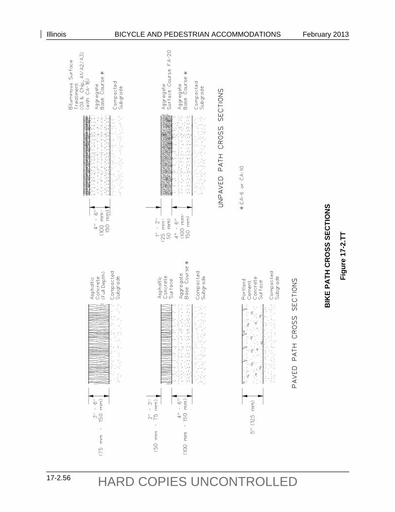
Illinois BICYCLE AND PEDESTRIAN ACCOMMODATIONS February 2013
17-2.56 HARD COPIES UNCONTROLLED
BIK
E PA
TH C
RO
SS S
ECTI
ON
S
Figu
re 1
7-2.
TT
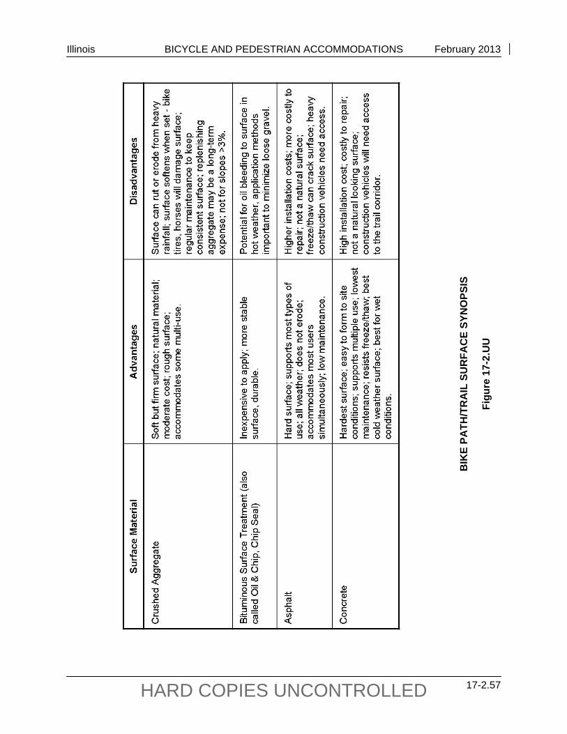
Illinois BICYCLE AND PEDESTRIAN ACCOMMODATIONS February 2013
17-2.57 HARD COPIES UNCONTROLLED
BIK
E PA
TH/T
RA
IL S
UR
FAC
E SY
NO
PSIS
Figu
re 1
7-2.
UU
Illinois BICYCLE AND PEDESTRIAN ACCOMMODATIONS February 2013
17-2.58 HARD COPIES UNCONTROLLED
17-2.04 Accommodations Through a Roundabout
Safety and usability of bicyclists through roundabouts depend on the details of the roundabout design and provisions unique for cyclists. At roundabouts, some cyclists may choose to travel like other vehicles, that is, through the circulatory roadway, while others may choose to travel like pedestrians, along the sidewalks. Roundabouts can be designed to simplify this choice for cyclists.
Since typical on-road bicycle travel speeds are between 12 mph and 20 mph (20 kph to 30 kph), roundabouts that are designed to constrain the speeds of motor vehicles to similar values will minimize the relative speeds between bicyclists and motorists, and thereby improve safety and usability for cyclists. Roundabouts designed for urban conditions should have a recommended maximum entry speed of 20 mph to 30 mph (30 kph to 50 kph). These speeds are generally compatible with bicycle travel.
17-2.04(a) Traversing Roundabouts like Motorized Vehicles
In general, cyclists who have the knowledge and skills to ride effectively and safely on collector roadways can navigate low-speed, single-lane roundabouts without much difficulty. Cyclists and motorists will travel at approximately the same speed, making it easier for bicyclists to merge with other vehicular traffic and take the lane within the roundabout itself; these are necessary actions for safe bicycling in a roundabout. Even at multilane roundabouts, many cyclists will be comfortable traveling through like other vehicles.
Where bicycle lanes or shoulders are used on approach roadways, they should be terminated in advance of roundabouts. The full-width bicycle lane should normally end at least 100 ft (30 m) before the edge of the circulatory roadway. Terminating the bike lane helps remind cyclists that they need to merge. An appropriate taper should be provided to narrow the sum of the travel lane and bike lane widths down to the appropriate width necessary to achieve desired motor vehicle speeds on the roundabout approach.
The taper should end prior to the crosswalk at the roundabout to achieve the shortest possible pedestrian crossing distance. A taper rate of 7:1 is recommended to accommodate a design speed of 20 mph (30 kph), which is appropriate for bicyclists and motor vehicles approaching the roundabout. To taper a 5 ft to 6 ft (1.4 m to 1.8 m) wide bicycle lane, a 40 ft (12 m) taper is recommended. The bicycle lane line should be dotted for 50 ft to 200 ft (15 m to 60 m) prior to the beginning of the taper and dropped entirely through the taper itself. A longer dotted line gives advance notice to cyclists that they need to merge, providing more room for them to achieve this maneuver and find an appropriate gap in traffic. See Figure 17-2.VV.
Bicycle lanes should not be located within the circulatory roadway of roundabouts. This would suggest that bicyclists should ride at the outer edge of the circulatory roadway, which can increase crashes resulting from exiting motorists who cut off circulating bicyclists and from entering motorists who fail to yield to circulating bicyclists.
At roundabout exits, an appropriate taper should begin after the crosswalk, with a dotted line for the bike lane through the taper. The solid bike lane line should resume as soon as the normal bicycle lane width is available.
Illinois BICYCLE AND PEDESTRIAN ACCOMMODATIONS February 2013
17-2.59 HARD COPIES UNCONTROLLED
17-2.04(b) Traversing Roundabouts like Pedestrians
Because some cyclists may not feel comfortable traversing some roundabouts in the same manner as other vehicles, bicycle ramps can be provided to allow access to the sidewalk or a shared use path at the roundabout. Bicycle ramps at roundabouts have the potential to be confused as pedestrian ramps, particularly for pedestrians who are blind or who have low vision. Therefore, bicycle ramps should only be used where the roundabout complexity or design speed may result in less comfort for some bicyclists.
Ramps normally should not be used at urban, one-lane roundabouts unless traffic speeds or other conditions (e.g., a right turn bypass lane) make circulating like other vehicles more challenging for bicyclists. Multilane roundabouts are more challenging for cyclists, and bike ramps can be used to provide the option to travel through the roundabout like a pedestrian.
Where bicycle ramps are provided at a roundabout, consideration should be given to providing a shared-use path or a widened sidewalk between the ramps at the roundabout. In areas with relatively low pedestrian use and where bicycle use of the sidewalks is expected to be low, the normal sidewalk width may be sufficient, however, in most situations, a minimum 10 ft (3 m) sidewalk width is recommended. If the sidewalk is designated as a shared-use path, appropriate shared-use path design details should be applied.
In some jurisdictions, local laws may prohibit cyclists from riding on sidewalks. In these areas, the following options could be considered:
Bicycle ramps can simply not be used.
Ramps could be installed using one of the following options:
- Signs could be posted to remind cyclists that they must walk their bicycles on the sidewalk.
- An exception could be made to allow cyclists to ride on the sidewalks at the roundabout; appropriate regulatory signs would need to be posted.
- The sidewalk could be designed and designated as a shared use path.
The design details of bicycle ramps are critical to provide choice to cyclists, ensure usability by cyclists, and reduce the potential for confusion of pedestrians, particularly those who are blind or who have low vision. Bicycle ramps should be placed at the end of the full-width bicycle lane where the taper for the bicycle lane begins. Cyclists approaching the taper and bike ramp will thus be provided the choice of merging left into the travel lane or moving right onto the sidewalk.
Bike ramps should not be placed directly in line with the bike lane or otherwise placed in a manner that appears to cyclists that the bike ramp and the sidewalk is the recommended path of travel through the roundabout. This encourages more sidewalk use by bicyclists, which can have a negative effect on pedestrians at the roundabout and may be less safe for bicyclists as well. Bicycle ramps should be placed at least 50 ft (15 m) prior to the crosswalk along the entry approach to the roundabout.
Illinois BICYCLE AND PEDESTRIAN ACCOMMODATIONS February 2013
17-2.60 HARD COPIES UNCONTROLLED
Wherever possible, bicycle ramps should be placed entirely within the planting strip between the sidewalk and the roadway. In these locations, the bicycle ramps should be placed at a 35° to 45° angle to the roadway and the sidewalk to enable cyclists to use the ramp even if pulling a trailer, but to discourage them from entering the sidewalk at high speed. The bike ramp can be fairly steep, with a slope potentially as high as 20%. If placed within the sidewalk area itself, the ramp slope must be built in a manner so that it is not a tripping hazard. Figure 17-2.VV illustrates several possible designs of bike ramps, depending on whether a planting strip is available and the available sidewalk width.
Bike ramps can be confusing for pedestrians with vision impairments. Detectable warnings are shown on the bicycle ramps in Figure 17-2.VV, but there is no definite guidelines at this time whether detectable warnings should be used, since the ramps are not intended for pedestrians. If detectable warnings are used and the ramp is placed in a planter strip, the detectable warning field should be placed at the top of the ramp since the ramp itself is part of the vehicular area for which the detectable warning is used. If the ramp is in the sidewalk itself, the detectable warning should be placed at the bottom of the ramp. Other aspects that can help keep pedestrians from misconstruing the bike ramp as a pedestrian crossing location include the angle of the ramp, the possible steeper slope of the ramp, and location of the ramp relatively far from the roundabout and crosswalk.
Bicycle ramps at roundabout exits should be built with similar geometry and placement as the ramps at roundabout entries. On exits, the angle between the bike ramp and the roadway can be as small as 20° since it is not necessary to encourage bicyclists to slow down as they reenter the roadway, but some angle is necessary so that blind pedestrians do not inadvertently travel down the ramp. Bike ramps should be placed at least 50 ft (15 m) after the crosswalk at the roundabout exit.
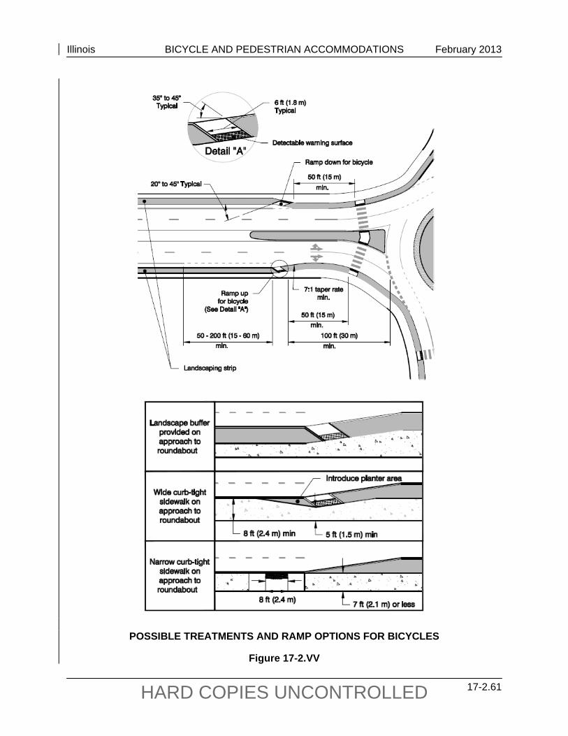
Illinois BICYCLE AND PEDESTRIAN ACCOMMODATIONS February 2013
17-2.61 HARD COPIES UNCONTROLLED
POSSIBLE TREATMENTS AND RAMP OPTIONS FOR BICYCLES
Figure 17-2.VV
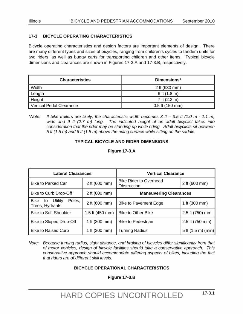
Illinois BICYCLE AND PEDESTRIAN ACCOMMODATIONS September 2010
17-3.1 HARD COPIES UNCONTROLLED
17-3 BICYCLE OPERATING CHARACTERISTICS
Bicycle operating characteristics and design factors are important elements of design. There are many different types and sizes of bicycles, ranging from children’s cycles to tandem units for two riders, as well as buggy carts for transporting children and other items. Typical bicycle dimensions and clearances are shown in Figures 17-3.A and 17-3.B, respectively.
Characteristics Dimensions*
Width 2 ft (630 mm) Length 6 ft (1.8 m) Height 7 ft (2.2 m) Vertical Pedal Clearance 0.5 ft (150 mm)
*Note: If bike trailers are likely, the characteristic width becomes 3 ft – 3.5 ft (1.0 m - 1.1 m)
wide and 9 ft (2.7 m) long. The indicated height of an adult bicyclist takes into consideration that the rider may be standing up while riding. Adult bicyclists sit between 5 ft (1.5 m) and 6 ft (1.8 m) above the riding surface while sitting on the saddle.
TYPICAL BICYCLE AND RIDER DIMENSIONS
Figure 17-3.A
Lateral Clearances Vertical Clearance
Bike to Parked Car 2 ft (600 mm) Bike Rider to Overhead Obstruction 2 ft (600 mm)
Bike to Curb Drop-Off 2 ft (600 mm) Maneuvering Clearances Bike to Utility Poles, Trees, Hydrants 2 ft (600 mm) Bike to Pavement Edge 1 ft (300 mm)
Bike to Soft Shoulder 1.5 ft (450 mm) Bike to Other Bike 2.5 ft (750) mm
Bike to Sloped Drop-Off 1 ft (300 mm) Bike to Pedestrian 2.5 ft (750 mm)
Bike to Raised Curb 1 ft (300 mm) Turning Radius 5 ft (1.5 m) (min)
Note: Because turning radius, sight distance, and braking of bicycles differ significantly from that
of motor vehicles, design of bicycle facilities should take a conservative approach. This conservative approach should accommodate differing aspects of bikes, including the fact that riders are of different skill levels.
BICYCLE OPERATIONAL CHARACTERISTICS
Figure 17-3.B

Illinois BICYCLE AND PEDESTRIAN ACCOMMODATIONS September 2010
17-3.2 HARD COPIES UNCONTROLLED
Illinois BICYCLE AND PEDESTRIAN ACCOMMODATIONS December 2011
17-4.1 HARD COPIES UNCONTROLLED
17-4 PEDESTRIAN ACCOMMODATIONS
17-4.01 General
Pedestrian accommodations are an integral part of urban and suburban transportation corridors. They facilitate pedestrian travel and access to public transportation, thereby contributing to alleviation of urban traffic congestion. The most pressing need for accommodation is at points of community development that result in pedestrian concentrations near or along the highway, such as at schools, public transportation stations and stops, local businesses, industrial plants, hospitals, churches, shopping centers, parking lanes, etc. Accommodations can include sidewalks, elevated walkways, grade-separated structures, stairs, curb ramps, and traffic signal devices.
17-4.02 Policies
See the bicycle and pedestrian policy discussed in Section 17-1.02.
Policies relating to construction and maintenance, including sidewalk/curb ramps for the disabled, are addressed in Chapter 58. Financial responsibilities for pedestrian accommodations within municipalities are addressed in Chapter 5.
17-4.03 Warrants
Pedestrian accommodations are required if they are not already available and any of the following conditions exist:
there is current evidence of frequent pedestrian activity;
there is a history of pedestrian-related crashes;
the roadway improvement will create a safety impediment to existing or anticipated pedestrian travel (e.g., adding lanes so that the improvement itself acts as a barrier to pedestrian traffic);
there is urban or suburban development that would attract pedestrian travel along the route to be improved;
pedestrian-attracting development is expected along the route within five years of project completion, either as documented in a local plan or anticipated as a factor of similar development history; and/or
the roadway provides primary access to a park, recreation area or other significant destination, or across a natural or man-made barrier.
Overpasses and underpasses will be evaluated on a case-by-case basis considering the type of pedestrian travel, travel generators (e.g., schools, factories, stadiums, parks, transit terminals,
Illinois BICYCLE AND PEDESTRIAN ACCOMMODATIONS December 2011
17-4.2 HARD COPIES UNCONTROLLED
shopping districts), the amount of anticipated non-motorized traffic, and the safety impacts of not providing the accommodations. Anticipated pedestrian trip length to generators should be 1 mile (2 km) or less and the adverse travel distance alleviated by construction to the facility should be greater than 0.5 miles (1 km).
17-4.04 Design
Sidewalks are typically 5 ft (1.5 m) wide. Where conditions do not allow for a width of 5 ft (1.5 m), a minimum clear sidewalk width 4 ft (1.2 m) is permissible as long as 5 ft by 5 ft (1.5 m by 1.5 m) passing spaces are provided at least every 200 ft (60 m). Sidewalks wider than 5 ft (1.5 m) should be considered if compatible with the local sidewalk network or if intended to accommodate a wider range of users, such as bicyclists. Facilities intended to also accommodate bicycle travel should follow the guidance in Section 17-2. Typical sections for sidewalks along roadways are presented in Chapter 48. All newly constructed or altered pedestrian accommodations shall meet the accessibility requirements in Chapter 58.
Project limits may be extended beyond highway improvements for reasonable distances to include necessary pedestrian facilities at nearby intersections, to provide access to public transportation facilities, or to avoid short sidewalks gaps. Any such extensions should be reflected in the Phase I report.
17-4.05 Documentation
When one or more of the warrants presented in Section 17-4.03 are met, appropriate and accessible pedestrian sidewalk accommodations shall be provided. When pedestrian accommodations will be included in the project, forward an electronic copy of the draft Phase I report to the Bureau of Design and Environment’s Bicycle and Pedestrian Coordinator. When projects do not meet warrants, send an electronic copy of the assessment of the warrants to the Bicycle and Pedestrian Coordinator to obtain concurrence. Exceptions to these design treatments either on the basis of cost or user safety require concurrence by the Bicycle and Pedestrian Coordinator and will be granted at coordination meetings after a sufficient review period. Total omissions on the basis of need, cost or user safety and that are within one mile of an urban area will require concurrence of the Secretary. Signed documentation of the Secretary’s concurrence shall be included in the draft Phase I report.
17-4.06 Pedestrian Accommodations During Construction
The Manual on Uniform Traffic Control Devices requires that alternate pedestrian access and walkways shall be provided whenever the existing pedestrian accommodations are affected by construction. See Section 55-2.01(d) and the Highway Standards for guidance.
Illinois BICYCLE AND PEDESTRIAN ACCOMMODATIONS December 2011
17-4.3 HARD COPIES UNCONTROLLED
17-4.07 Maintenance and Jurisdiction
Jurisdiction and maintenance of pedestrian walkways are considered a local responsibility and should be coordinated with local agencies early in the planning process; see Chapter 5.
If the local agency chooses not to participate in the pedestrian accommodation, the Department will request that that local agency pass a local resolution indicating their non-participation and have this noted in the Phase I report. Proposed resolution language is included in Section 17-7.

Illinois BICYCLE AND PEDESTRIAN ACCOMMODATIONS December 2011
17-4.4 HARD COPIES UNCONTROLLED
Illinois BICYCLE AND PEDESTRIAN ACCOMMODATIONS September 2010
17-5.1 HARD COPIES UNCONTROLLED
17-5 REFERENCES
The following are applicable references for bicycle facility accommodation:
1. Guide for the Development of Bicycle Facilities, AASHTO, 1999.
2. Selecting Roadway Design Treatments to Accommodate Bicycles, Federal Highway Administration, 1994.
3. Trails for the Twenty-First Century Planning, Design, and Management Manual for Multi-Use Trails, Rails-to-Trails Conservancy, 1993.
4. Arizona Bicycle Facilities Planning and Design Guidelines, Arizona Bicycle Task Force, 1988.
5. Bicycle Planning and Facility Workshop Manual, Northwestern University Traffic Institute.
6. Illinois Manual on Uniform Traffic Control Devices (ILMUTCD), IDOT.
7. National Bicycling and Walking Study: Case Study No. 24 Current Planning Guidelines and Design Standards Being Used By State and Local Agencies for Bicycle and Pedestrian Facilities, Federal Highway Administration, 1994.
8. North Carolina Bicycle Facilities Planning and Design Guidelines, North Carolina Department of Transportation, 1994.
9. Oregon Bicycle and Pedestrian Plan, Oregon Department of Transportation, 1998.
10. Recommendations for Accessibility Guidelines: Recreational Facilities and Outdoor Developed Areas, Access Board Recreation Access Advisory Committee, 1994 or subsequent edition.
11. Standard Specifications for Road and Bridge Construction, Illinois Department of Transportation.
12. Warrants for Pedestrian Over and Underpasses, Federal Highway Administration, 1984, Report # FHWA-RD-84/082.
13. Checklist for Organizations and Public Coordination (Figure 17-1.C) addresses:
League of Illinois Bicyclists, 2550 Cheshire Drive, Aurora, IL 60504.
Illinois Department of Natural Resources, Office of Planning and Realty, One Natural Resources Way, Springfield, IL 62702-1271.
Trails for Illinois, 1639 Burr Oak Road, Homewood, IL 60430
Illinois BICYCLE AND PEDESTRIAN ACCOMMODATIONS September 2010
17-5.2 HARD COPIES UNCONTROLLED
Active Transportation Alliance, 9 W. Hubbard Street,, Suite 402, Chicago, IL 60654-6545.
All projects involving bicycle accommodation for the Department will be in accordance with Reference Publications 1, 2, and 3 above. For projects involving separate bikeways, guidance beyond the AASHTO Guide (i.e., Reference Publication 1) is available in Reference Publication 3.
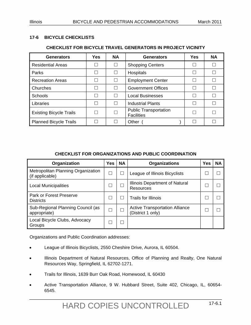
Illinois BICYCLE AND PEDESTRIAN ACCOMMODATIONS March 2011
17-6.1 HARD COPIES UNCONTROLLED
17-6 BICYCLE CHECKLISTS
CHECKLIST FOR BICYCLE TRAVEL GENERATORS IN PROJECT VICINITY
Generators Yes NA Generators Yes NA
Residential Areas Shopping Centers
Parks Hospitals
Recreation Areas Employment Center
Churches Government Offices
Schools Local Businesses
Libraries Industrial Plants
Existing Bicycle Trails Public Transportation Facilities
Planned Bicycle Trails Other ( )
CHECKLIST FOR ORGANIZATIONS AND PUBLIC COORDINATION
Organization Yes NA Organizations Yes NAMetropolitan Planning Organization (if applicable) League of Illinois Bicyclists
Local Municipalities Illinois Department of Natural Resources
Park or Forest Preserve Districts Trails for Illinois
Sub-Regional Planning Council (as appropriate) Active Transportation Alliance
(District 1 only)
Local Bicycle Clubs, Advocacy Groups
Organizations and Public Coordination addresses:
League of Illinois Bicyclists, 2550 Cheshire Drive, Aurora, IL 60504.
Illinois Department of Natural Resources, Office of Planning and Realty, One Natural Resources Way, Springfield, IL 62702-1271.
Trails for Illinois, 1639 Burr Oak Road, Homewood, IL 60430
Active Transportation Alliance, 9 W. Hubbard Street, Suite 402, Chicago, IL, 60654-6545.
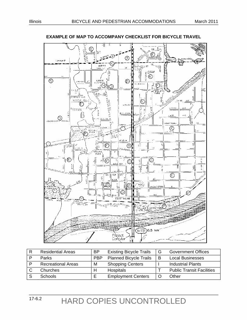
Illinois BICYCLE AND PEDESTRIAN ACCOMMODATIONS March 2011
17-6.2 HARD COPIES UNCONTROLLED
EXAMPLE OF MAP TO ACCOMPANY CHECKLIST FOR BICYCLE TRAVEL R Residential Areas BP Existing Bicycle Trails G Government Offices P Parks PBP Planned Bicycle Trails B Local Businesses P Recreational Areas M Shopping Centers I Industrial Plants C Churches H Hospitals T Public Transit Facilities S Schools E Employment Centers O Other
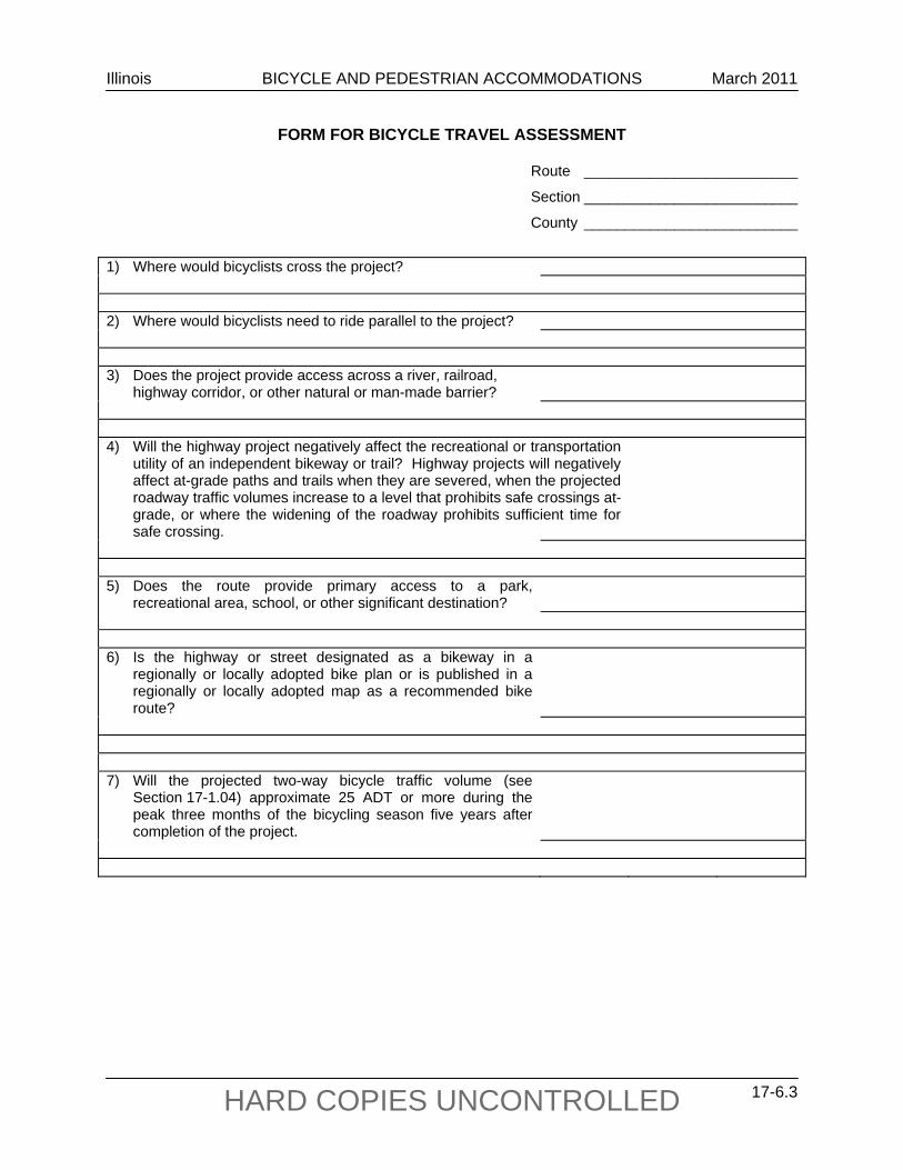
Illinois BICYCLE AND PEDESTRIAN ACCOMMODATIONS March 2011
17-6.3 HARD COPIES UNCONTROLLED
FORM FOR BICYCLE TRAVEL ASSESSMENT
Route __________________________
Section __________________________
County __________________________
1) Where would bicyclists cross the project? 2) Where would bicyclists need to ride parallel to the project? 3) Does the project provide access across a river, railroad, highway corridor, or other natural or man-made barrier?
4) Will the highway project negatively affect the recreational or transportation
utility of an independent bikeway or trail? Highway projects will negatively affect at-grade paths and trails when they are severed, when the projected roadway traffic volumes increase to a level that prohibits safe crossings at-grade, or where the widening of the roadway prohibits sufficient time for safe crossing.
5) Does the route provide primary access to a park,
recreational area, school, or other significant destination?
6) Is the highway or street designated as a bikeway in a
regionally or locally adopted bike plan or is published in a regionally or locally adopted map as a recommended bike route?
7) Will the projected two-way bicycle traffic volume (see
Section 17-1.04) approximate 25 ADT or more during the peak three months of the bicycling season five years after completion of the project.

Illinois BICYCLE AND PEDESTRIAN ACCOMMODATIONS March 2011
17-6.4 HARD COPIES UNCONTROLLED
Illinois BICYCLE AND PEDESTRIAN ACCOMMODATIONS September 2010
17-7.1 HARD COPIES UNCONTROLLED
17-7 PROPOSED RESOLUTION LANGUAGE FOR NON-PARTICIPATING LOCAL AGENCIES
WHEREAS, The Illinois Department of Transportation (IDOT) has the power to approve and determine the final plans, specifications and estimates for all State highways; and WHEREAS, IDOT’s projects must adequately meet the State’s transportation needs, exist in harmony with their surroundings, and add lasting value to the communities they serve; and WHEREAS, IDOT must embrace principles of context sensitive design and context sensitive solutions in its policies and procedures for the planning, design, construction, and operation of its projects for new construction, reconstruction, or major expansion of existing transportation facilities by engaging in early and ongoing collaboration with affected citizens, elected officials, interest groups, and other stakeholders to ensure that the values and needs of the affected communities are identified and carefully considered in the development of transportation projects; and WHEREAS, Bicycle and pedestrian ways must be given full consideration in the planning and development of transportation facilities, including the incorporation of such ways into State plans and programs; and WHEREAS, The State’s complete streets law requires bicycle and pedestrian ways to be established in or within one mile of an urban area in conjunction with the construction, reconstruction, or other change of any State transportation facility, except in pavement resurfacing projects that do not widen the existing traveled way or do not provide stabilized shoulders, or where approved by the Secretary of Transportation based upon documented safety issues, excessive cost or absence of need; and WHEREAS, During the development of highway projects throughout the State, IDOT gives consideration to accommodating bicyclists and pedestrians on a need-basis; and WHEREAS, IDOT has presented the (local authority), for its consideration, a bicycle and/or pedestrian improvement with funding to be split 80% State, 20% local with maintenance to be provided by (IDOT/unit of local government); therefore, be it RESOLVED, That the (local authority) hereby rejects IDOT’s proposed bicycle and/or pedestrian improvement and acknowledges that such rejection will result in a cancellation of the proposed improvement; and be it further RESOLVED, That a suitable copy of this resolution be presented to the Project Engineer associated with the proposal, or his or her equivalent, within IDOT.

Illinois BICYCLE AND PEDESTRIAN ACCOMMODATIONS September 2010
17-7.2 HARD COPIES UNCONTROLLED