Chapter nine - porior.com nine-bridges.pdf · Chapter nine Railroad Car and ... Bridge Components:...
18
Chapter nine Railroad Car and other types of short span bridges for stream simulation at road crossings Filename: C:\fishpassdesign\chapter 9 bridges\chapter nine -latest revision\chapter nine-Jan 03l- short span bridges.wpd
Transcript of Chapter nine - porior.com nine-bridges.pdf · Chapter nine Railroad Car and ... Bridge Components:...

Chapter nine
Railroad Car and other types of short span bridges for stream simulation atroad crossings
Filename: C:\fishpassdesign\chapter 9 bridges\chapter nine -latest revision\chapter nine-Jan 03l- short span bridges.wpd

ii
Table of Contents
Railroad Car and other short span bridges an alternative for stream simulation . . . . . . . . . . . . . 1Objectives and Purpose . . . . . . . . . . . . . . . . . . . . . . . . . . . . . . . . . . . . . . . . . . . . . . . . . 1Economy of Scale . . . . . . . . . . . . . . . . . . . . . . . . . . . . . . . . . . . . . . . . . . . . . . . . . . . . . 2Loadings . . . . . . . . . . . . . . . . . . . . . . . . . . . . . . . . . . . . . . . . . . . . . . . . . . . . . . . . . . . 2Bridge Components: a brief glossary . . . . . . . . . . . . . . . . . . . . . . . . . . . . . . . . . . . . . . 2Types of Bridge Superstructures . . . . . . . . . . . . . . . . . . . . . . . . . . . . . . . . . . . . . . . . . . 3Types of Bridge Abutments . . . . . . . . . . . . . . . . . . . . . . . . . . . . . . . . . . . . . . . . . . . . . . 4Bridge layout, Sizing and Alignment . . . . . . . . . . . . . . . . . . . . . . . . . . . . . . . . . . . . . . . 4
1. Clearance for floating Debris: . . . . . . . . . . . . . . . . . . . . . . . . . . . . . . . . . . . 42. Low Water Bridge considerations ( vented ford). . . . . . . . . . . . . . . . . . . . . . 43. Width of Stream opening under bridge: . . . . . . . . . . . . . . . . . . . . . . . . . . . . 54. Rock Slope Protection . . . . . . . . . . . . . . . . . . . . . . . . . . . . . . . . . . . . . . . . . 55. Guardrails, sidewalks and or curbs . . . . . . . . . . . . . . . . . . . . . . . . . . . . . . . . 5
Spread Footing abutment options for railroad car, portable, or temporary bridges onprivate lands. . . . . . . . . . . . . . . . . . . . . . . . . . . . . . . . . . . . . . . . . . . . . . . . . . . 6Gabion Basket Abutment . . . . . . . . . . . . . . . . . . . . . . . . . . . . . . . . . . . . . . . . . 6Precast Abutment Beams . . . . . . . . . . . . . . . . . . . . . . . . . . . . . . . . . . . . . . . . . 7Rock or Riprap Abutments. . . . . . . . . . . . . . . . . . . . . . . . . . . . . . . . . . . . . . . . 7Log abutments . . . . . . . . . . . . . . . . . . . . . . . . . . . . . . . . . . . . . . . . . . . . . . . . . 8
Railroad Car Bridge Superstructures: for portable or temporary bridges . . . . . . . . . . . . 9Railroad Car Bridges- an overview . . . . . . . . . . . . . . . . . . . . . . . . . . . . . . . . . . 9Discussions with Suppliers and Installers of Railroad Car Bridges . . . . . . . . . 10
Schnitzer Steel . . . . . . . . . . . . . . . . . . . . . . . . . . . . . . . . . . . . . . . . . . 10Jim McKenzie . . . . . . . . . . . . . . . . . . . . . . . . . . . . . . . . . . . . . . . . . . 10Rick Franklin Corporation . . . . . . . . . . . . . . . . . . . . . . . . . . . . . . . . . 10Available Bridges from Rick Franklin Corporation as of Feb 2002 . . . 11Skip Gibbs Company . . . . . . . . . . . . . . . . . . . . . . . . . . . . . . . . . . . . . 11Oscar Marteney, . . . . . . . . . . . . . . . . . . . . . . . . . . . . . . . . . . . . . . . . . 12Keith Comstock . . . . . . . . . . . . . . . . . . . . . . . . . . . . . . . . . . . . . . . . . 12
Concrete bridges . . . . . . . . . . . . . . . . . . . . . . . . . . . . . . . . . . . . . . . . . . . . . . . . . . . . . 13 Bridges with Wooden and Concrete Decks . . . . . . . . . . . . . . . . . . . . . . . . . . . . . . . . . 13WEYCO Minibridges . . . . . . . . . . . . . . . . . . . . . . . . . . . . . . . . . . . . . . . . . . . . . . . . . 14Mini-bridge or Modular Box Culvert . . . . . . . . . . . . . . . . . . . . . . . . . . . . . . . . . . . . . . 15

1
Forest Road Fish Passage Guide- State of Oregon
2Forest Practices guidebook for British Columbia.
Railroad Cars and other short span bridges Page 1
Railroad Car and other short span bridges analternative for stream simulation
“A bridge is a stream crossing structure that spans the stream and is placed on abutments and/orpiers located in or near the stream. Bridges in terms of natural resource protection should alwaysbe the preferred alternative because they allow for a natural flow of sediments and change streamhabitat the least. However, when economic considerations and logistics of the particular site aretaken into account there are often better economic alternatives than a bridge. ”1
As noted above bridges are the preferred and often the most expensive stream crossing. Their advantage over other alternatives is they can span the stream without inhibiting streamflow andaquatic movements. A bridge is accordingly considered the best option for stream simulationdesigns when designed and constructed with abutments that do not constrict the stream channel. Inthis author’s opinion the use and availability of short span bridges will increase and overtime may replace the use of culverts at most stream crossings. Culverts in general are constructed withwidths which do not span the bank full width of the channel and leave a constricted entrance forlarger flows.
“The decision to use a bridge over a culvert can be driven by the basis of economics, engineering,site parameters, environmental, hydraulic and or debris requirements. Bridges are chosen whereculverts are no longer capable of carrying the design flows or managing the expected debrishazards and where fish passage requirements cannot be met by culverts due to stream gradient orwhere sites contain significant habitat values such as spawning locations. Bridges are also lessprone to beaver problems and are chosen over culverts in many areas where beavers are asignificant concern.”2
Objectives and Purpose
The objective of this chapter is to provide an overview of several types of short span bridgesfound on private lands or on forest highways in Southwestern Oregon with observations on theiruse.
A list of suppliers is included. Using that list a reader can request site specific information andcurrent catalogs.
This chapter is not intended as a design guide or a code book for the design of bridges. State andother regulatory agency have these codes and guides already in place. Bridges are normallydesigned by a registered engineer in the state or province where the bridge will be constructed.

3Forest Road Fish Passage Guide Book- State of Oregon
Railroad Cars and other short span bridges Page 2
Economy of Scale
“Bridges become economical as stream size increases or in steep gradient streams where many ofthe culvert alternatives won’t work.”3
Loadings
Bridges are designed for specific loadings. The size of their girders, stringers, decks aredependent on their intended use. The first selection criterion for a bridge type is to determine thedesign loading for that bridge.
1.Private bridges: Must meet county loading requirements for fire access. Private land owners canselect from all the available options in that they can limit the liability to themselves and those theyallow to enter unto their properties.
2.Logging roads: Loading is often determined by the size and wheel configuration of the loggingequipment which will be used. In general equipment on logging roads will be moved apart from thelow boys and transport trucks that hauled them to the property. The result is often a higherconcentrated load then would be required if the vehicle was on a lowboy with pups and jeeps.Bridges on logging roads have a mixed liability. The bridge is a private bridge to the land ownerbut contractors will use it for heavy loads that may or may not have been anticipated when thebridge was installed. The type of bridge chosen will be limited by state forest practice actrequirements and the insurance requirements of contractors operating on the property.
3.Farm Bridges: These are often short span structures that carry lightweight trucks and farmequipment. These bridges are often required to be wider then logging or home access bridges. These bridges often are designed for very low design loadings.
4.County and Government Roads: Bridges on county and government roads must be designed inaccordance with established codes. They also must be rateable and inspected at no less then a 2year interval. The design loading for these bridges will be often less then for logging roads. Their design will require a strict compliance with codes.
Bridge Components: a brief glossary
Abutment; A substructure supporting the end of a single span or the extreme end of a multi-spansuperstructure.
Pier: A substructure built to support the ends of the spans of a multiple span superstructure atintermediate points between the abutments.
Superstructure: The entire portion of a bridge structure that primarily receives and supportshighway ,pedestrian, or other traffic loads and transfers the applied loads to the bridgesubstructure.
Substructure: The abutments, piers, bents or their constructions built to support the superstructure

Railroad Cars and other short span bridges Page 3
and transmits loads to the foundation.
Stringer. A longitudinal beam supporting the bridge deck.
Span. When applied to the design of beam, girder truss, or arch superstructures, the distance centerto center of the end bearing or the distance between the lines of action of the reactions.
Types of Bridge Superstructures
There are numerous superstructure options. A brief list of the most common would include thefollowing.
1. Timber bridges- sawn timber, glued laminated, dowel laminated, and nail laminated .
2. Timber bridges- log stringer: Build by cabling together trees fallen in the construction area.May have a gravel or timber deck.
3. Railroad Cars- boxcars
4. Railroad cars- flatcars
5. Flatbed truck trailers
6. Steel I beam with timber decks
7. Steel I beams with concrete deck panels bolted perpendicular to the deck
8. Hinged Portable Bridge- Normally available from a local National Guard Unit for atemporary Crossing
9. Concrete Bridges: Prestressed girders typed by span length
10. Concrete Bridges: Concrete Slab- non prestressed.- precast panels which can be locallyfabricated.

Railroad Cars and other short span bridges Page 4
Types of Bridge Abutments
The bridge abutments are earth retaining structures that support the superstructure at both ends.Bridge abutments vary by size and shape. The appropriate selection is developed from a review ofthe soils, the type of superstructure, the geometry of the site, and economics. The following arecommon types seen on forest or private roads.
1. Pile Bents: Wooden or concrete posts setting on a spread footing.
2. Surface bearing spread footings: The most common footing for temporary bridges orportable bridges. These footings may set on a rock base, a retaining wall, on rockoutcrops, and in some cases on soils.
3. Pile Abutments: Soft clay, soft soil foundations. Normally includes a concrete pile cap.
4. Sawn Lumber Frame bents. Normally see variations of this design on railroad crossings.
5. Pile Bent: Used when foundation is on soft clay or soft soils to transfer the loads to rock orfirm material below.
6. Pedestal. A short column on an abutment or pier which directly supports thesuperstructure. Loads are transmitted by the pedestal to the footings below.
Bridge layout, Sizing and Alignment
1. Clearance for floating Debris:
Per Oregon Forest Practices Act a minimum of 3 feet of clearance is required between theestimated 50 year design flow elevation and the bottom of the superstructure. This 3 feet ofclearance is needed to pass large woody debris that is floating downstream. A method forcalculating flow capacity of a crossing is included in the Oregon Stream Restoration guide.
2. Low Water Bridge considerations ( vented ford).
A. A low fill design must contain the following elements to be approve. The structure mustbe large enough to handle the 2 year event.
B. The flood plain must be at least 3 times the active channel width or 100 feet at theproposed road crossing.
C. An overflow depression must be constructed in the road fill at a location away from thestructure and at an elevation lower ten than the top of the bridge.
D. The road surface must be armored with rock of sufficient size and depth to protect the fillwhen a flood flow occurs.
E. The bridge should be anchored and designed to resist the horizontal loads caused by waterand debris against the sides of the structure.

Railroad Cars and other short span bridges Page 5
3. Width of Stream opening under bridge:
Bridge should be designed with a minimum width of the active channel width of the stream thebridge is crossing. Using a program such as WinXPRO we can model the velocity and depth offlow through the bridge crossing for various widths. Select a width that does not constrict thestream or change the backwater characteristics of the area. On private lands the county willnormally want a certificate showing of no rise .
4. Rock Slope Protection
In streams where degradation is possible the channel under the bridge should be protected fromdown cutting. This protection will prevent undermining of the bridge abutments as well asprotection of upstream ecosystem. In addition riprap slope protection should be placed aroundthe structure to the estimated height of the peak storm event. See commentary on riprap design inchapter two.
5. Guardrails, sidewalks and or curbs
On county ,state and federal collector roads guardrails are required at the approach and across bridges. An exception to this policy is on low use federal forest access roads. Guardrails areoptional depending on the agency. Curbs are a design option and have more to do with drainagethen protection of the rail system. The guard rail system on the bridge and approaches are designed to AASHTO bridge standards.
On private roads rails and curbs are optional. For the most part short curbs are added to theoutside of the decks to guide traffic across the bridge and control surface drainage.

Railroad Cars and other short span bridges Page 6
Spread Footing abutment options for railroad car, portable, or temporarybridges on private lands.
The abutment for temporary bridges will typically be designed to the same standards as abutmentsfor any other type of superstructure. An important difference is these superstructure types canwithstand a considerable degree of settlement with minimal or no structural damage.
Assuming the bridge site is not a public road and some settlement is acceptable, the followingabutment options have been used.
1. Gabion Baskets filled with rock or rock and concrete
2. Precast Concrete blocks
3. Stone or Riprap Abutments
4. Reinforced Rock or aggregate .
5. Logs placed under the ends and notched to distribute the load.
6. Timbers and Planks for load distribution.
Gabion Basket Abutment
Gabions have been used as retaining walls for bridges and have been used as abutments totemporary bridges . I discussed installation options with two suppliers: Hilkiker Retaining WallCompany of Eureka and Maccaferri Gabions of West Coast Inc.
The gabions provide an abutment wall and disburse the loading of the bridge to the soil below. Thefollowing plan is proposed. Construct the gabions to grade as shown on the drawings. Place a 6 x12 wood or concrete pad across the top of the baskets. The purpose of the beam is to provide alevel support for the bridge and to distribute the load of the bridge equally across the Gabionbaskets. An equally good alternative would be to concrete grout the rock in the baskets after theyare assembled.
Gabion Baskets are supplied locally by Hilfiker Company of Eureka Oregon. The cost of twobaskets 12' x 3' x 3' delivered to a work site near Coos Bay would be $250.00. Those basketswould require 8 Cubic Yards of Fractured Rock to fill. The cost of that rock is estimated at 8 x$25 =200.00. The total materials cost is $450.00. The baskets would still need to be filled andtied. The total installed cost would be around $1000.00 A logical improvement would be to fillthe voids in the basket with concrete after they are filled though this would not be necessary.
1. Installation of Gabion abutments for a temporary bridge crossing.:
1. Excavate to depth indicated on drawings,
2. Install baskets level. Fill with rock to design grade. Optional pour concrete around thestones when their filled and level off to better set the bridge superstructure.

Railroad Cars and other short span bridges Page 7
3. Install wooded beam across top of baskets.
4. Set bridge on beams
Precast Abutment Beams
Abutment beams for bridges are available from commercial and non commercial sources. Thefollowing suppliers of Precast Concrete abutment beams for temporary bridges were found on theSouth Coast of Oregon.
1. Morse Brothers of Harrisburg Oregon
2. Hilfiker Retaining Wall Company, Eureka, California
3. Joe Buldac of Bandon, Oregon 541-347-2848
4. Rick Franklin Company, Lebanon ,Oregon 541-451-1275
These beams are not difficult to fabricate and can be constructed on site if necessary. The costfrom the two suppliers above is minimal and contractors will often order the abutment beamsrather then make them.
The beams are typically 2' wide , 2' thick and 11' long. These blocks would be set directly fromthe delivery truck onto a rocked pad. A typical pad would be constructed by constructing a threefoot wide x two foot deep rock base . Use 3" to 6" rock for this base. If base is on weak soils thedesign engineer may require stabilization fabric placed in layers in the base rock.. The concreteblocks would then be placed onto the rock pad. The estimated costs for the beams in place issummarized below.
Blocks 2 each at $500 = $1000.00
Rock 4 cubic yards x 25.00= $100.00
Installation = $200.00
The costs of the concrete beams is comparable with the gabion baskets noted above. With therock subbase they each will have the same bearing capacity . Settlement is not considered aproblem with either of the structures as long as we have a footprint of approximately 3 ‘ x 12feet. Increasing that footprint will further reduce any concerns of settlement.
Rock or Riprap Abutments.
A common abutment on farm and forest roads is a riprap fill constructed at the edge of the streamor into the bank. The top of the rock works are filled with smaller stones and then gravel toprovide a level base. The bridge is then set directly on the rock or on a concrete abutment beamplaced on top of the rock.
The size of the stones are normally in the range of 2 -3 foot or larger with smaller stones placedbetween to fill the voids. Typically the rock is classified as Class IV or Class V Riprap. Therock is typically placed on a 1-1/2:1 fill slope or steeper. In wet areas a geotextile is placed under

Railroad Cars and other short span bridges Page 8
the rock. As noted above soil conditions will dictate the type of rock base or abutment appropriate for the site.
Log abutments
Log abutments have been used extensively for temporary crossings under railroad cars and othertypes of temporary bridges. . They are easily installed and easily replaced assuming there remainsa viable supply of logs. See photo below. Depending on the availability of large diameter logsthis may or may not be an economical alternatives. The life of a typical log abutment on the coastis 10 years depending on the type of wood use. In drier areas such as near Roseburg the logs areexpected to last 2 or 3 times longer.

4 Bridges Constructed From Railroad Cars, Thomas J. Parson, Arkansas State UniversityDepartment of Engineering, Final Report TRC 8901, Dec l991.
5 Railroad Car Bridges: Asset or Liability, Bruce Suprenant ,
Railroad Cars and other short span bridges Page 9
Railroad Car Bridge Superstructures: for portable or temporary bridges
Railroad Car Bridges- an overview
“A common modular bridge system is the railroad car bridge constructed from salvaged railroadcars. The frame acts as the bridge stringers and the steel or timber deck as the road surface. Bridges have been constructed from box, gondola, and flat cars which are approximately 9 footwide and come in lengths up to 86+ feet.”4
A. Railroad cars are manufactured by approximately 12 companies
B. Scrapping occurs when repair costs exceed the depreciated value of the car. Age and thecondition of the running gear are the most often reasons that cars are scrapped.
C. Selection of a railroad car for a bridge should include a physical inspection of the car body.This condition survey should determine:
A. Length and width of the car.
B. Spacing of all members
C. Location and condition of bent, twisted or cracked members
D. Yield Strength of the members can be determined by the Hardness Tess and stress -straincurves developed from samples. When purchasing a car the following tests are suggestedby Professor Parsons of the University of Arkansas.
A. Test the main members for cracks using a dye penetrate
B. Support the car on timbers and drive over it with a D8 tractor
C. Support the car on timbers , load it and measure deflections, then comparecalculated deflections vs. actual stiffness.
E. Flatcar Frames are typically stronger then boxcar frames. Several suppliers offer only theflatcars to insure that a light weight car will not be used for commercial traffic.
F. When using two or more layers of timber decking, do not nail the top layer to the bottomlayer. Lag screws and more effective connectors as traffic vibration tend to loosen nails.
G. “Foundations for railroad car bridges are not much different from foundations for anybridge structure. Railroad cars bridges however concentrate the loading in a single areaunder the main longitudinal beams. A wide steel plate placed under the main beams isessential for the railroad car bridge.”5

6The Bridge, Michigan Technological University, Vol 3, No. 2 Winter 1989
Railroad Cars and other short span bridges Page 10
H. “Two center I shaped beams carry the load to each end of the car. The moment resistanceof the car is dependent on the size, shape, and strength of these two members. Two exteriormembers usually consisting of a single channel are connected by tapered members the mainlongitudinal I shaped beam . The load on the exterior channel is transferred to the mainbeams through the tapered members. Miscellaneous angles running in both directionsstabilize the compression edge of exterior channels and interior beams.”6
I. Abutment Connections; Local contractors all indicate they do not attach the bridge to theabutment of spread footing type foundations. They will routinely cable the bridge to a treeas an anchor in case of high water. The recommended design is to bolt the bridge to theabutment on one end and install a sliding connections on the other. A connection detail is savailable from the University of Arkansas. That detail is included in typical drawingsincluded in Appendix B to this chapter. Abutment beams should set directly under theaxles (circular plate) The cars are designed for the greatest strength with the loading onthe axles . Shims will be needed between the side beams and the abutment as the axleplates are often lower then the side beams at this point. Local Suppliers of Railroad Carbridges
J. The following suppliers were located.
A. Rick Franklin Corporation , Lebanon, Oregon, 541-451-1275 541-258-5153 (home)
B. Schnitzer Steel Products, Portland, Oregon 800-888-5571 ( 6922)
C. Jim McKenzie, White City, Oregon 541- 831-1553
D. Oscar Marteney, 541- 998-6605, 541- 729-7993
E. Skip Gibbs Company, Redwood Valley, California, email: [email protected] Phone 707-485-5822
Discussions with Suppliers and Installers of Railroad Car Bridges
Schnitzer Steel
Schnitzer Steel will provide railroad cars for bridges installed with steel decks. If clients want thecars modified or trimmed they will trim the cars to the requested length. Their inventory fluctuatesduring the year. Clients should call to find out availability then visit their company to select abridge and discuss any modifications needed.
Jim McKenzie
He gets his cars from H and S construction . At the time ,I called him they did not have any carsavailable.
Rick Franklin Corporation

Railroad Cars and other short span bridges Page 11
Rick Franklin said he had several good bridges available at this time in addition to the concreteabutments noted in his brochure. He has a brochure that will be forwarded to prospective clients.
Available Bridges from Rick Franklin Corporation as of Feb 2002
53 foot 10'-6" width $9000 each
56 foot 10'-6" width
57 foot 10'-6 “ width
60 foot 20 available,$10,000 each
62 foot 10'-6" width 1 available
89 foot 9'-6" width 12 available $15,000 with flatsteel decks
Mr. Franklin made the following recommendations on the use of railroad cars. He also provided usa list of references who have purchased bridges from their company.
1. Width of Deck:
Their company does not recommend that decks be wider then 14 feet on a single car.Using a 14 foot wide deck will provide a running surface between rails of approximately12'. If additional width is needed they recommend using two bridges. There is a high riskthat traffic will wander to side of bridge and a wheel fall through deck..
2. Concrete Abutment Beams:
Their company sells a precast abutment beam for $500.00 each. The bridge can be setdirectly on this beam over a prepared foundation. The beams are 11' x 2' x 2'.
3. Types available: In their opinion Box cars have very low strengths. Accordingly, theyonly sell Flat Cars for use as bridges.
Skip Gibbs Company
The Skip Gibbs Company has a large inventory of bridges on hand which they purchased severalyears ago. Their company is one of the leading suppliers of railroad cars for bridges in Northern nCalifornia. They have an impressive brochure which includes an extensive list of completed sites.
Skip Gibbs company will provide a quote for bridges installed to any site. Unloading and settingof the bridge is the responsibility of the client. They strongly advised not installing a 16 foot widedeck on a single railroad car bridges. The risks of an accident was too great in their opinion.
There company recommends a local engineer who will select a bridge for clients based on theclients foundation and layout requirements. That engineer will then load rate the bridge.

Railroad Cars and other short span bridges Page 12
Oscar Marteney,
Oscar Marteney is a retired logger who had installed these bridges. Now he locates the cars andarranges for the delivery of the cars to purchasers. He has a good record of providing quality carsto purchasers at reasonable prices. The availability of cars varies from year to year. At the timeof my conversation with him, he has only a few left. He said they extremely well made, heavyduty flat car bridges. He included several photos of the bridges. I have included those photos andhis quote in the appendix. The bridges he is selling come from Kenwich Washington. He isasking $6000 for the 60 foot long flat car and $6500 for the 65 foot long flatcar. As he said theyare very heavy bridges and may require several loaders or a crane to unload
Keith Comstock
Mr. Comstock is the lead engineer for Plumb Tree working out of their Coos Bay office. Hiscompanies installs 3 to 5 railroad car bridges a year on their tree farms. They installed 10 railroadcar bridges one year.
1. Generally, their company will use a wooden deck system on the railroad car bridges. Thediagonal beams are 8 x 8 pressure treated timbers placed 20" on center. The runningplanks are 4 x 12 pressure treated timbers which are placed three to each side. Theoutside to outside dimensions of their bridges are 14 feet. Bridge spikes are used to securethe 4 x12 s to the 8 x 8's.
2. They contract the installation of these bridges. Dave Palmer of Palmer Construction doesthe majority of their work..
3. They buy their cars from the suppliers noted above. Mr. Comstock noted that we shouldask for heavy cars with a load rating of at least 140,000 lbs. In recent years they havepurchased cars with ratings up to 180,000 lbs.
4. They normally set the cars on a riprap foundation with a leveling course to bring them tograde. He noted that each site was different. He suggested that I visit some of theirinstallations on Camas Creek Road outside of Sitkum. They purchased their abutmentbeams from Joe Buldac of Bandon. ( 347-2848)

Railroad Cars and other short span bridges Page 13
Concrete bridges
The leading supplier of concrete bridges in South Western Oregon is Morse Brothers. Their officeis in Harrisburg. They engineer and provide precast or prestressed deck and abutment beams. They will provide a brochure describing their products and work with their clients to help select thebeam system that best fits their site.
Concrete bridges can be used on short span crossings of any length. In general the cost of materialsdelivered is in the area of $30.00 per square foot. Bridge decks are similar to decks for precastculverts discussed later in this chapter but will have fundamental differences. The decks arebolted to the abutments as well as having diagonal bolts between them . In addition the decks aregrouted together with shear keys that make the entire superstructure act as a single unit.
Concrete bridge decks for short span bridges are typically precast and prestressed. Companiessuch as Morris Brothers have a quality control program that maintains the temperature andhumidity needed for concrete to reach design strengths. Bridges with spans greater than 65 feetwill require deck sections such as a box girder or T beam. The longer spans may also have cast inplace decks.
Bridges with Wooden and Concrete Decks
Bridge superstructures can be constructed on site, delivered as components, or delivered as modularunits partly assembled. Companies provide an entire range of options. Decks can be attached ondelivery or assembled in place. Local economics will dictate which is the best for a particular client. For federal or state agencies having a load rated superstructure provided by a vendor is verydesirable.
The following companies provide prefabricated steel and wood bridge superstructures to SouthWestern Oregon.
Name of Company Location Phone Number
Big R Manufacturing Greeley Colorado 1-800-234-0734
Shur Span Construction Ltd West Vancouver, B.C. 1-604-925-3337
Hamilton Bridge Company-Easy Bridge Supplier
Eugene ,Oregon, 1-541-746-2426
Permapost Hillsboro ,Oregon 1-503-648-4156
Western Wood Structures Tualatin, Oregon 1-503-692-6900
Supplier will provide quotes on a variety of configurations such as Steel beams with wood decks,Steel beams with composite concrete decks, Steel beams with concrete non composite slab decks,Glue-Lam beams with wood decks, etc.
Steel and wood beams are competitively priced . The supplier from of wood bridges noted that forspans up to 55 foot spans wood bridges are less expensive then other types even with replacementestimated in 85 years. The total costs between options is worth the time of a detailed comparison. .

Railroad Cars and other short span bridges Page 14
WEYCO Minibridges
A local timber company has developed a culvert with spans of up to 25 feet. Technically thestructure is a bridge with a soil deck. . The supports are totally to the footings. Two variations ofdecks have been used wood and concrete slabs. The wood decks were constructed from salvagedwood beams. The concrete decks were constructed with their own crews. The costs of thesestructures are significantly lower then commercially provided culverts. Design Features:
1 Deck: Recycled treated timbers
2 foundations: Ecology blocks on grade
3 Surfacing: aggregate surface
4 Cost= $12,000 each+-

Railroad Cars and other short span bridges Page 15
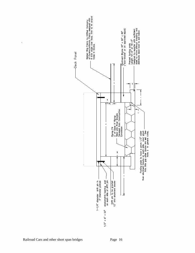
Mini-bridge or Modular Box Culvert
A variation on the mini-bridge design was developed using concrete blocks and a precast slab. These components can be field assembled into various sizes and shapes. Various suppliers havebeen contacted to provide the blocks and slabs. At this time we are considering:
1 Abutment blocks: Local Supplier in Roseburg or Coos Bay, or Hilfiker Company of EurekaCalifornia.
2 Abutment slabs- prestressed for reduced weight: Morris Brothers of Harrisburg, Oregon
3 Welded Wire soil reinforcements: Hilfiker Company of Eureka, California.
The structure is hydraulicly similar to the open bottom arch and like other open bottom structures may requires a riprap blanket. The depth of the riprap if needed will depend on the site. See chaptertwo- foundation riprap design for sizing. Widening the structure to full stream simulation widthswill reduce the velocities and depth and potentially the amount of costs for the foundationimprovements. Preliminary material costs have been developed for component.
1. Deck slabs- $23.00 per sq foot with curbs ,bolts, and fabric
2. Abutment panels or blocks -$11.00 sq foot
3. Prefabricated footings- $44.00 per linear foot.
Total costs for materials was competitive with a pipe arch and slightly less then an open bottomarch. The advantages to design include
1. Structure does not rely on soil strength for structural integrity.
2. Approximately the same length to install as a culvert.
3. For minor costs can widen structure to full simulation criterion per chapter four.
4. All components prefabricated. which should translate into a lower installation costs.
5. See drawings on following page for details of assembly.
Railroad Cars and other short span bridges Page 16
.