CHAPTER 14eecs.ucf.edu/~mingjie/EEL3342/11.pdf©2010 Cengage Learning CHAPTER 14 DERIVATION OF STATE...
54
©2010 Cengage Learning CHAPTER 14 DERIVATION OF STATE GRAPHS AND TABLES This chapter in the book includes: Objectives Study Guide 14.1 Design of a Sequence Detector 14.2 More Complex Design Problems 14.3 Guidelines for Construction of State Graphs 14.4 Serial Data Code Conversion 14.5 Alphanumeric State Graph Notation Programmed Exercises Problems
Transcript of CHAPTER 14eecs.ucf.edu/~mingjie/EEL3342/11.pdf©2010 Cengage Learning CHAPTER 14 DERIVATION OF STATE...

©2010 Cengage Learning
CHAPTER 14
DERIVATION OF STATE GRAPHS AND TABLES
This chapter in the book includes:ObjectivesStudy Guide
14.1 Design of a Sequence Detector14.2 More Complex Design Problems14.3 Guidelines for Construction of State Graphs14.4 Serial Data Code Conversion14.5 Alphanumeric State Graph Notation
Programmed ExercisesProblems

©2010 Cengage Learning
Design of a Sequence Detector
To illustrate the design of a clocked Mealy sequential circuit, we will design a sequence detector. The circuit is of the form:
Figure 14-1: Sequence Detector to be Designed

©2010 Cengage Learning
Suppose we want to design the sequence detector so that any input sequence ending in 101 will produce an output Z = 1 coincident with the last 1. The circuit does not reset when a 1 output occurs. A typical input sequence and the corresponding output sequence are:
X = 0 0 1 1 0 1 1 0 0 1 0 1 0 1 0 0
Z = 0 0 0 0 0 1 0 0 0 0 0 1 0 1 0 0 (14-1)
(time: 0 1 2 3 4 5 6 7 8 9 10 11 12 13 14 15

©2010 Cengage Learning
Initially, we do not know how many flip-flops will be required, so we will designate the circuit states as S0, S1, etc. We will start with a reset state designated S0. If a 0 input is received, the circuit can stay in S0 because the input sequence we are looking for does not start with a 0.

©2010 Cengage Learning
However, if a 1 is received, the circuit must go to a new state (S1) to “remember” that the first input in the desired sequence has been received.
Figure 14-2
©2010 Cengage Learning
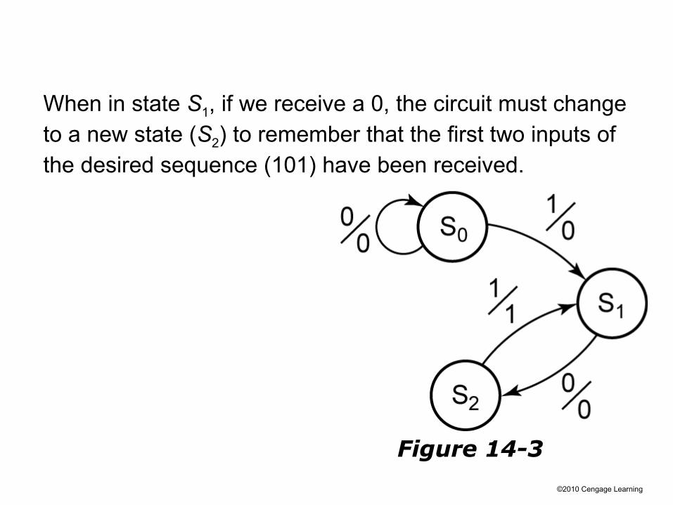
When in state S1, if we receive a 0, the circuit must change to a new state (S2) to remember that the first two inputs of the desired sequence (101) have been received.
Figure 14-3
©2010 Cengage Learning
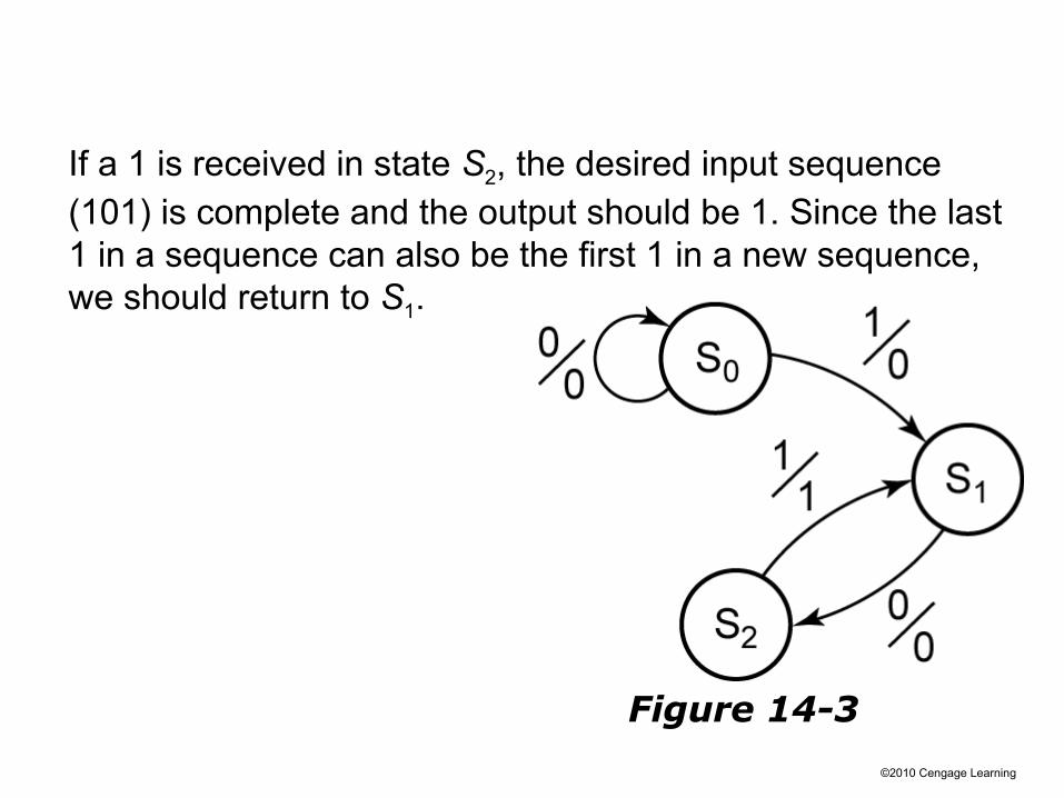
If a 1 is received in state S2, the desired input sequence (101) is complete and the output should be 1. Since the last 1 in a sequence can also be the first 1 in a new sequence, we should return to S1.
Figure 14-3

©2010 Cengage Learning
If a 1 input occurs when in state S1, we can stay in S1 because the sequence is simply restarted. If a 0 input occurs in state S2, we have received two 0’s in a row and must reset the circuit to S0 because 00 is not part of the desired sequence.
Figure 14-4: Mealy State Graph for
Sequence Detector

©2010 Cengage Learning
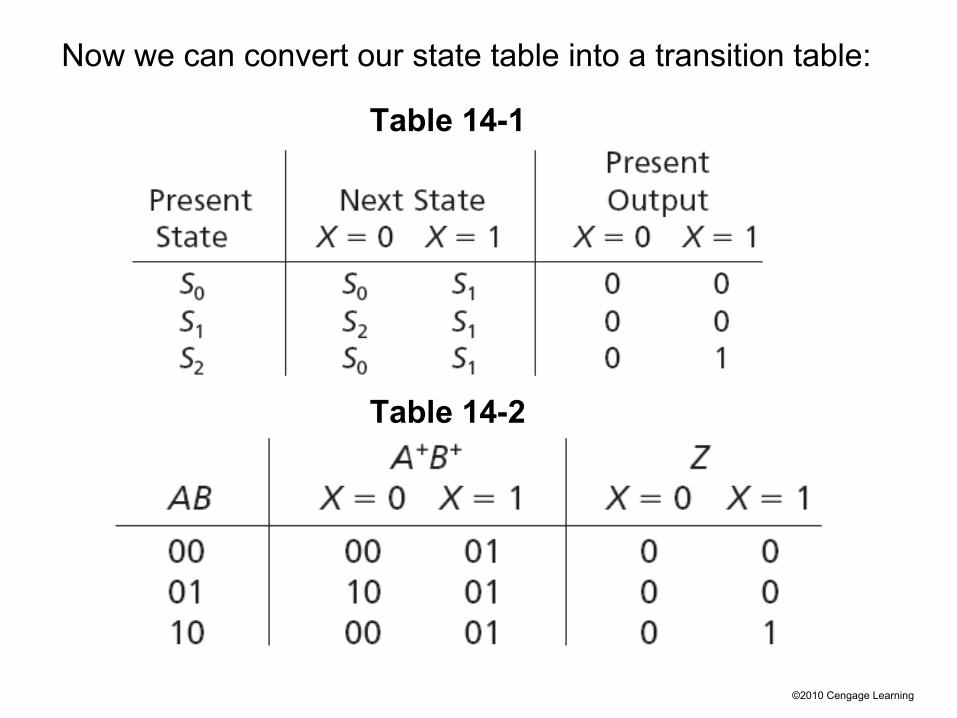
We can then convert our state graph to a state table:
Figure 14-4
Table 14-1
Since there are 3 states, we only need 2 flip-flops for the circuit (2 memory bits).
©2010 Cengage Learning
Now we can convert our state table into a transition table:
Table 14-1
Table 14-2
©2010 Cengage Learning
Section 14.1 (p. 433)
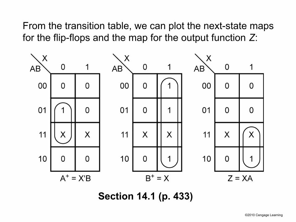
From the transition table, we can plot the next-state maps for the flip-flops and the map for the output function Z:

©2010 Cengage Learning
Figure 14-5
Now we can draw the circuit corresponding to the equations we derived:

©2010 Cengage Learning
The procedure for finding the state graph for a Moore machine is similar to that used for a Mealy machine, except that the output is written with the state.
We will rework the previous example as a Moore machine: the circuit should produce an output of 1 only if an input sequence ending in 101 has occurred.
©2010 Cengage Learning
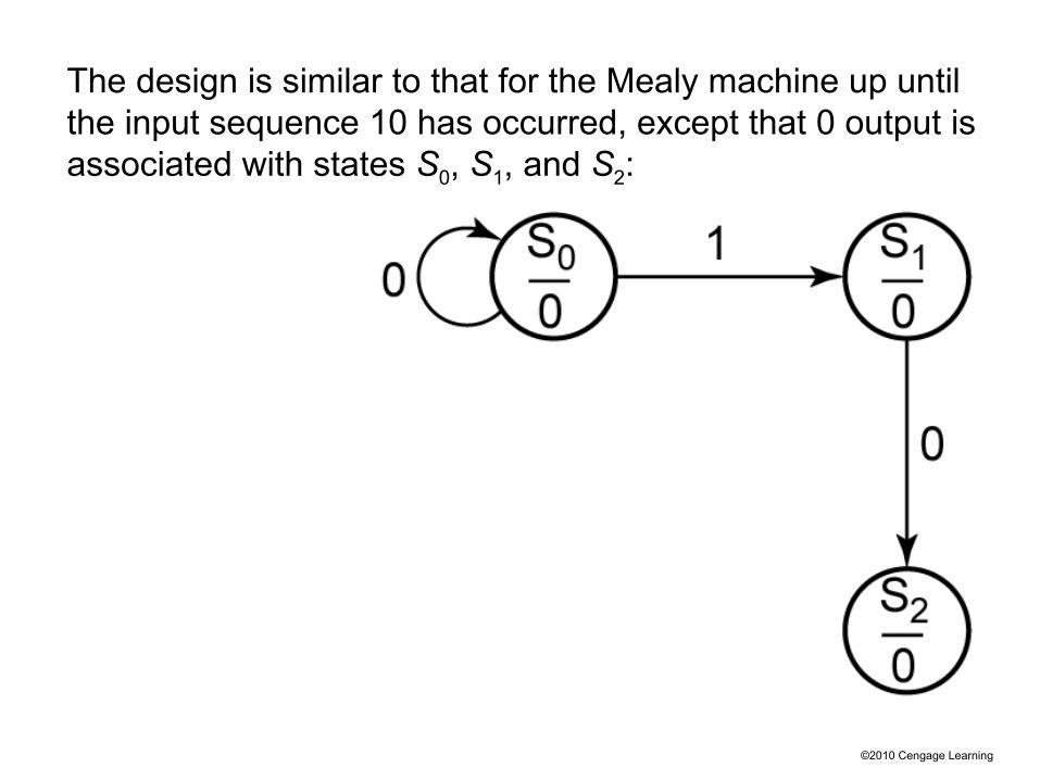
The design is similar to that for the Mealy machine up until the input sequence 10 has occurred, except that 0 output is associated with states S0, S1, and S2:
©2010 Cengage Learning
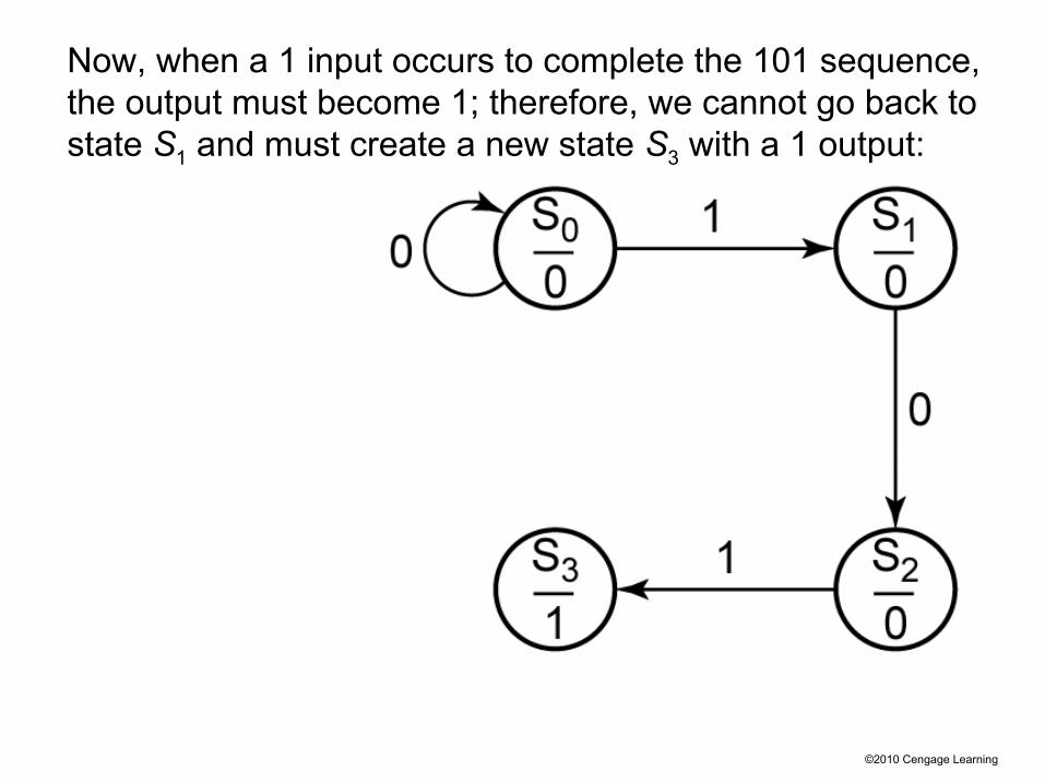
Now, when a 1 input occurs to complete the 101 sequence, the output must become 1; therefore, we cannot go back to state S1 and must create a new state S3 with a 1 output:

©2010 Cengage Learning
We now complete the graph, as shown below. Note the sequence 100 resets the circuit to S0. A sequence 1010 takes the circuit back to S2 because another 1 input should cause Z to become 1 again:
©2010 Cengage Learning
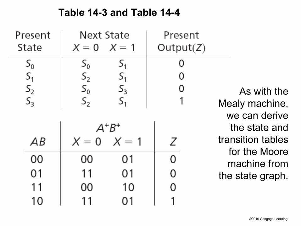
Table 14-3 and Table 14-4
As with the Mealy machine,
we can derive the state and
transition tables for the Moore machine from
the state graph.

©2010 Cengage Learning
More Complex Design Problems
Now we will derive a state graph for a sequential circuit of somewhat greater complexity than the previous examples.
For this circuit, the output Z should be 1 if the input sequence ends in either 010 or 1001, and Z should be 0 otherwise.
Ex:
Section 14.2 (p. 435)
©2010 Cengage Learning
We will start construction of the state graph by working with the two sequences which lead to a 1 output. Then, we will later add arrows and states as required to make sure that the output is correct for other cases.
Mealy Example

©2010 Cengage LearningFigure 14-7
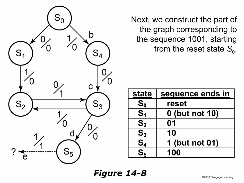
©2010 Cengage LearningFigure 14-8
Next, we construct the part of the graph corresponding to
the sequence 1001, starting from the reset state S0.
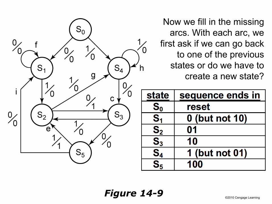
©2010 Cengage LearningFigure 14-9
Now we fill in the missing arcs. With each arc, we
first ask if we can go back to one of the previous
states or do we have to create a new state?
©2010 Cengage Learning
Moore Example
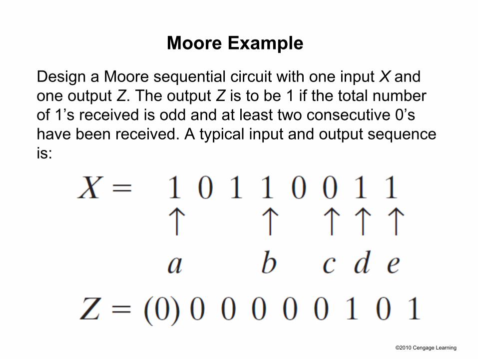
Design a Moore sequential circuit with one input X and one output Z. The output Z is to be 1 if the total number of 1’s received is odd and at least two consecutive 0’s have been received. A typical input and output sequence is:
©2010 Cengage Learning
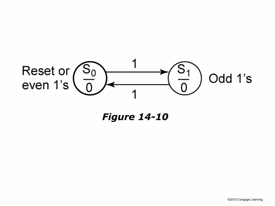
Figure 14-10

©2010 Cengage Learning
Figure 14-11
©2010 Cengage Learning
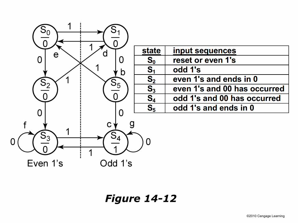
Figure 14-12

©2010 Cengage Learning
Guidelines for Construction of State Graphs
Section 14.3 (p. 439)
Although there is no one specific procedure which can be used to derive state graphs or tables for every problem, the following guidelines should prove helpful:
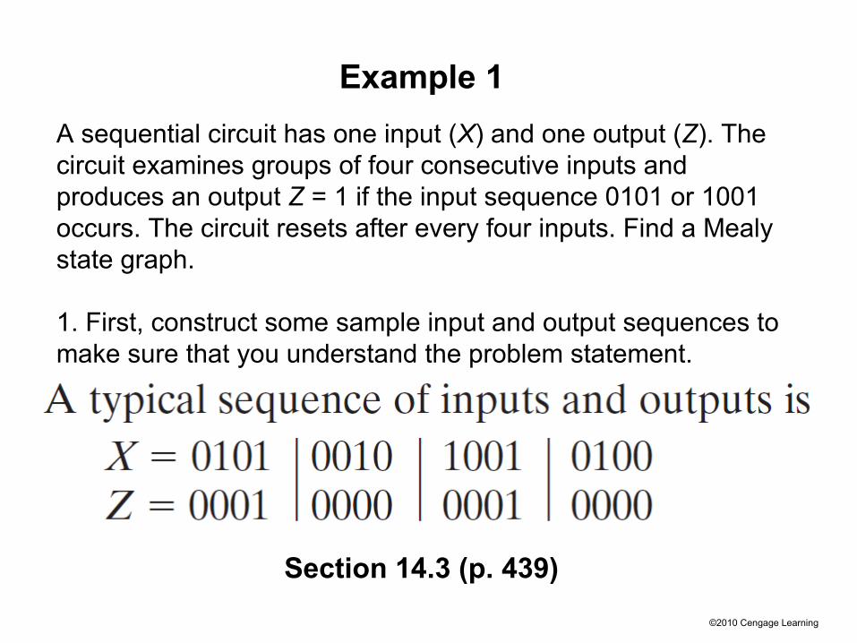
1. First, construct some sample input and output sequences to make sure that you understand the problem statement.
2. Determine under what conditions, if any, the circuit should reset to its initial state.
3. If only one or two sequences lead to a nonzero output, a good way to start is to construct a partial state graph for those sequences.
©2010 Cengage Learning
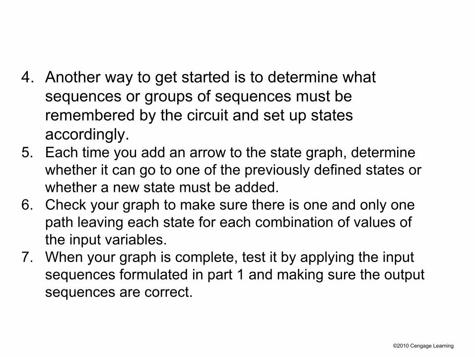
4. Another way to get started is to determine what sequences or groups of sequences must be remembered by the circuit and set up states accordingly.
5. Each time you add an arrow to the state graph, determine whether it can go to one of the previously defined states or whether a new state must be added.
6. Check your graph to make sure there is one and only one path leaving each state for each combination of values of the input variables.
7. When your graph is complete, test it by applying the input sequences formulated in part 1 and making sure the output sequences are correct.
©2010 Cengage Learning
Example 1
Section 14.3 (p. 439)
A sequential circuit has one input (X) and one output (Z). The circuit examines groups of four consecutive inputs and produces an output Z = 1 if the input sequence 0101 or 1001 occurs. The circuit resets after every four inputs. Find a Mealy state graph.
1. First, construct some sample input and output sequences to make sure that you understand the problem statement.
©2010 Cengage Learning
Since the circuit examines groups of four consecutive inputs and resets after each group of four, the circuit should reset to S0 after every fourth input is received.
2. Determine under what conditions, if any, the circuit should reset to its initial state.

©2010 Cengage LearningFigure 14-13: Partial State Graph for Example 1
4. Another way to get started is to determine what sequences or groups of sequences must be remembered by the circuit and set up states accordingly.
©2010 Cengage Learning
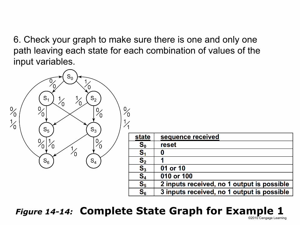
Figure 14-14: Complete State Graph for Example 1
6. Check your graph to make sure there is one and only one path leaving each state for each combination of values of the input variables.
©2010 Cengage Learning
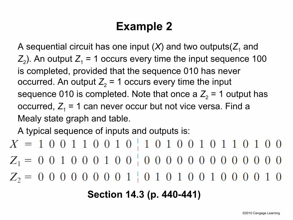
Example 2
Section 14.3 (p. 440-441)
A sequential circuit has one input (X) and two outputs(Z1 and Z2). An output Z1 = 1 occurs every time the input sequence 100 is completed, provided that the sequence 010 has never occurred. An output Z2 = 1 occurs every time the input sequence 010 is completed. Note that once a Z2 = 1 output has occurred, Z1 = 1 can never occur but not vice versa. Find a Mealy state graph and table.A typical sequence of inputs and outputs is:
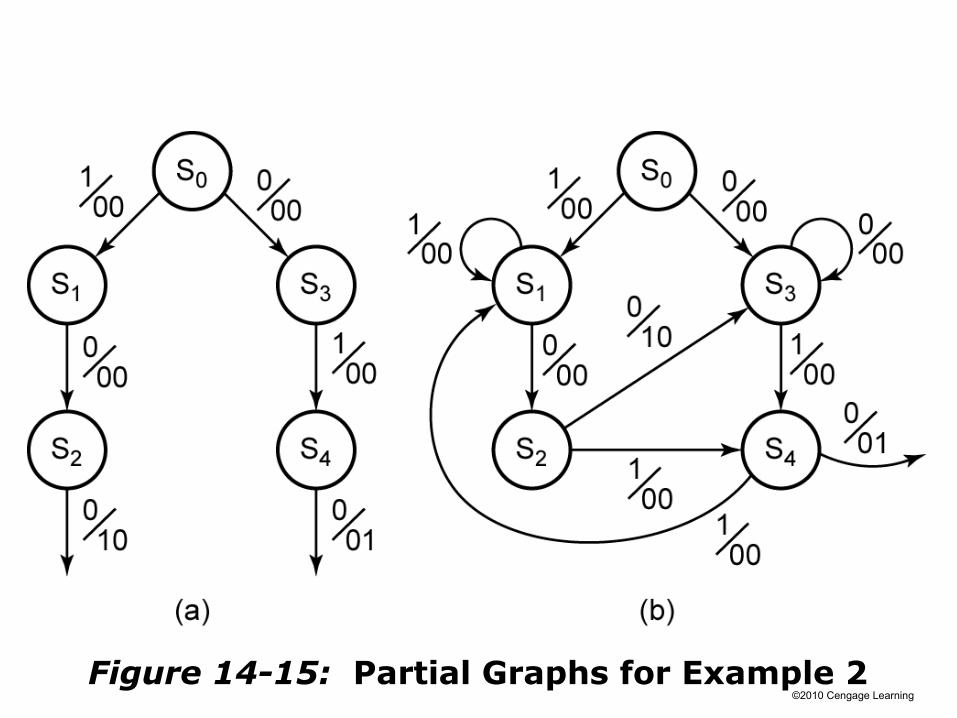
©2010 Cengage Learning
Figure 14-15: Partial Graphs for Example 2

©2010 Cengage Learning
Table 14-5 State Descriptions for Example 2
Keeping track of what is remembered by each state will help us make the correct state graph.
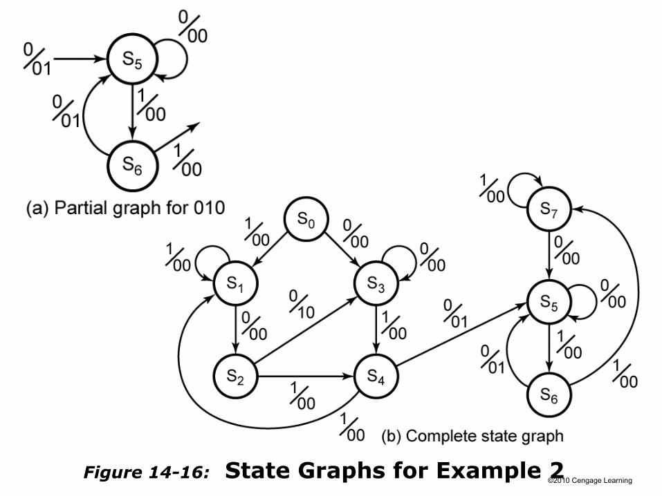
©2010 Cengage LearningFigure 14-16: State Graphs for Example 2

©2010 Cengage Learning
Table 14-6.

©2010 Cengage Learning
Example 3
Section 14.3 (p. 443)
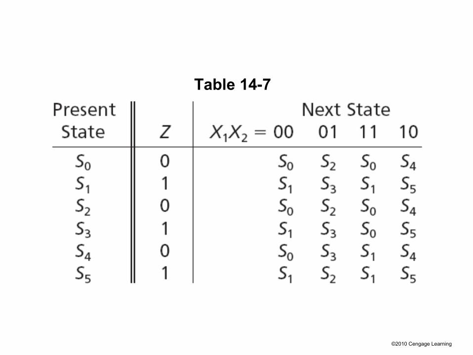
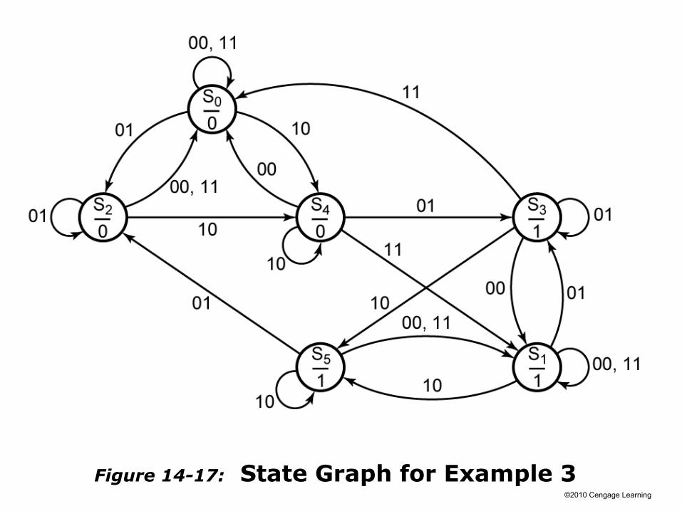
A sequential circuit has two inputs (X1, X2) and one output (Z). The output remains a constant value unless one of the following input sequences occurs:(a) The input sequence X1X2 = 01, 11 causes the output to become 0.(b) The input sequence X1X2 = 10, 11 causes the output to become 1.(c) The input sequence X1X2 = 10, 01 causes the output to change value.
(The notation X1X2 = 01, 11 means X1 = 0, X2 = 1 followed by X1 = 1, X2 = 1.)Derive a Moore state graph for the circuit.

©2010 Cengage Learning
©2010 Cengage Learning
Table 14-7
©2010 Cengage Learning
Figure 14-17: State Graph for Example 3

©2010 Cengage Learning
Serial Data Code Conversion
Section 14.4 (p. 444)
As a final example of state graph construction, we will design a converter for serial data. Binary data is frequently transmitted between computers as a serial stream of bits.
A clock signal is often transmitted along with the data so the receiver can read the data at the proper time.
Alternatively, only the serial data is transmitted, and a clock recovery circuit (called a digital phase-locked loop) is used to regenerate the clock signal at the receiver.
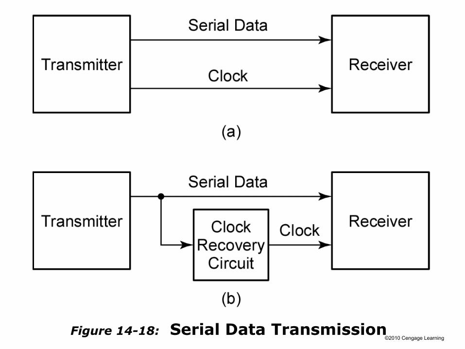
©2010 Cengage LearningFigure 14-18: Serial Data Transmission
©2010 Cengage Learning
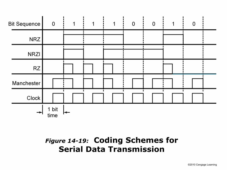
Figure 14-19: Coding Schemes forSerial Data Transmission

©2010 Cengage Learning
Figure 14-20a:
Mealy Circuit for NRZ-to-Manchester Conversion

©2010 Cengage Learning
Figure 14-20b:
Mealy Circuit for NRZ-to-Manchester Conversion

©2010 Cengage Learning
Figure 14-20cd:
Mealy Circuit for NRZ-to-Manchester Conversion

©2010 Cengage Learning
Figure 14-21a:
Moore Circuit for NRZ-to-Manchester Conversion

©2010 Cengage Learning
Figure 14-21bc:
Moore Circuit for NRZ-to-Manchester
Conversion
(c) State table

©2010 Cengage Learning
Alphanumeric State Graph Notation
Section 14.5 (p. 448)
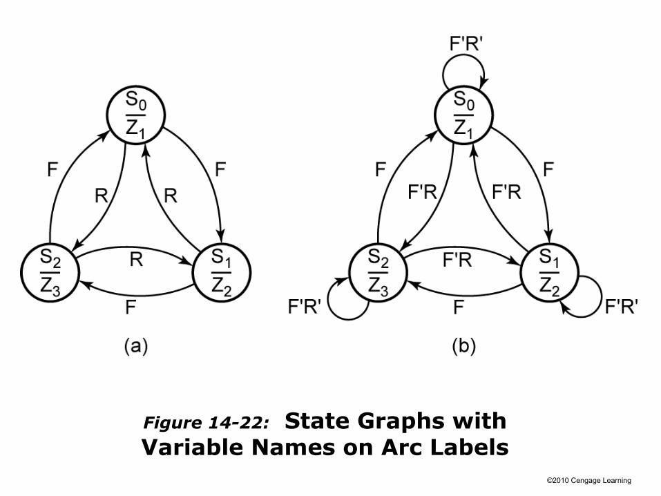
When a state sequential circuit has several inputs, it is often convenient to label the state graph arcs with alphanumeric input variable names instead of 0’s and 1’s.
©2010 Cengage Learning
Figure 14-22: State Graphs withVariable Names on Arc Labels

©2010 Cengage Learning
Table 14-8. State Table for Figure 14-22

©2010 Cengage Learning
Properly Specified State Graphs
Section 14.5 (p. 449)
In general, a completely specified state graph has the following properties:
1. When we OR together all input labels on arcs emanating from a state, the result reduces to 1.
2. When we AND together any pair of input labels on arcs emanating from a state, the result is 0.

©2010 Cengage Learning
Alphanumeric Notation for Mealy State Graphs
Section 14.5 (p. 449)
XiXj / ZpZq means if inputs Xi and Xj are 1 (we don’t care what the other input values are), the outputs Zp and Zq are 1 (and the other outputs are 0). That is, for a circuit with four inputs (X1, X2, X3, and X4) and four outputs (Z1, Z2, Z3, and Z4), X1X4′ / Z2Z3 is equivalent to 1--0 / 0110.
This type of notation is very useful for large sequential circuits where there are many inputs and outputs.