CHAPTER G-2 GATES OTHER THAN RADIAL GATE G-2.1 Key … · inadvertently opening of the gate, cyclic...
38
G-2-1 CHAPTER G-2 GATES OTHER THAN RADIAL GATE G-2.1 Key Concepts There are multiple gate types used in flood control and navigation dams that could fail and affect the operation of the dam or lead to a dam breach. Failures of the gates could be a result of additional loading for which the gates were not designed (hydrologic, impact or seismic), inadvertently opening of the gate, cyclic loading during normal operation, etc. Example of gates used in flood control dams include Tainter gates, drum gates, roller gates, ring gates, and gates used in the outlet works or penstocks. Failure of these gates could result in increased flow downstream and could lead to loss of life and economic consequences. Tainter gates are evaluated in detail in two other chapters of this manual. Gates used in navigation locks include miter gates, vertical lift gates, reverse tainter gates, submergible gates and sector gates. For navigation dams, examples of gates used to control pool include roller gates (submergible and unsubmergible), Tainter gates (submergible and unsubmergible), lift (sluice) gates and wickets. Failure of these could results in loss of navigation and loss of pool leading to economic consequences. In some instances, for high hazard navigation dams, failure of a gate could potentially result in loss of life. G-2.2 Description of Gate Types and Potential Failure Modes Drum Gates A drum gate consists of a hollow steel structure, hinged on the upstream side that floats in a bath of water contained within a float chamber bounded by reinforced concrete walls. These gates are unique in that the gates are lowered to release water, with water flowing over the top of the gates. Error! Reference source not found.shows a cross section through a drum gate. Water is let into the float chamber to raise the gate (raising the reservoir level and shutting off spillway flow) and water is released from the chamber to lower the gate (initiating spillway flows and lowering the reservoir level). Gate seals prevent water from going around the gates, and gate stops or seats keep the gates from rotating too far up and out of the float chamber. A drain is used in order to
Transcript of CHAPTER G-2 GATES OTHER THAN RADIAL GATE G-2.1 Key … · inadvertently opening of the gate, cyclic...

G-2-1
CHAPTER G-2 GATES OTHER THAN RADIAL GATE
G-2.1 Key Concepts
There are multiple gate types used in flood control and navigation dams that could fail and affect
the operation of the dam or lead to a dam breach. Failures of the gates could be a result of
additional loading for which the gates were not designed (hydrologic, impact or seismic),
inadvertently opening of the gate, cyclic loading during normal operation, etc. Example of gates
used in flood control dams include Tainter gates, drum gates, roller gates, ring gates, and gates
used in the outlet works or penstocks. Failure of these gates could result in increased flow
downstream and could lead to loss of life and economic consequences. Tainter gates are
evaluated in detail in two other chapters of this manual.
Gates used in navigation locks include miter gates, vertical lift gates, reverse tainter gates,
submergible gates and sector gates. For navigation dams, examples of gates used to control pool
include roller gates (submergible and unsubmergible), Tainter gates (submergible and
unsubmergible), lift (sluice) gates and wickets. Failure of these could results in loss of navigation
and loss of pool leading to economic consequences. In some instances, for high hazard
navigation dams, failure of a gate could potentially result in loss of life.
G-2.2 Description of Gate Types and Potential Failure Modes
Drum Gates
A drum gate consists of a hollow steel structure, hinged on the upstream side that floats in a bath
of water contained within a float chamber bounded by reinforced concrete walls. These gates are
unique in that the gates are lowered to release water, with water flowing over the top of the gates.
Error! Reference source not found.shows a cross section through a drum gate. Water is let into
the float chamber to raise the gate (raising the reservoir level and shutting off spillway flow) and
water is released from the chamber to lower the gate (initiating spillway flows and lowering the
reservoir level). Gate seals prevent water from going around the gates, and gate stops or seats
keep the gates from rotating too far up and out of the float chamber. A drain is used in order to

G-2-2
keep unwanted water from filling the gate. The drain is usually connected from the interior of the
gate by a flexible hose to an outlet through the concrete at some location.
Figure G-2-1 Cross Section through Drum Gate

G-2-3
These gates are rather complex, and require maintenance to ensure reliable operation of all the
valves, piping, and structural features. Some of the vulnerabilities that should be considered
when performing a risk analysis of these types of gates are as follows:
Inadvertent lowering of a gate (and release of life-threatening flows) can occur under
normal operations if water is lost from the float chamber or the gate fills with water (and
is no longer buoyant). The ability of the float chamber inlet conduits and valves to supply
water to the chamber faster than it is released through the outlet conduits and valves must
be assessed. The size of the conduits and valves is one consideration. The type,
robustness, and maintenance of the valves and piping are other considerations. Similarly,
the type, robustness, and maintenance of the internal gate drains and hoses must also be
considered.
Puncturing of a gate from rockfall, spalling concrete or other sources could allow the gate
to fill with water faster than the drain can release water, causing dropping of the gate and
life-threatening downstream flows.
Seismic loading on the gates can affect several components of a drum gate including:
o The hinge pins that tie the gate to the float chamber wall
o The hinge pin anchorage that ties the hinge pins to the float chamber wall
o The float chamber walls themselves
o The piping and valves that control the flow into and out of the float chamber and
gate drain
o The gate seats that keep the gates from rotating too far up and out of the float
chamber.
o The piers, which if they deflect can cause gate binding between piers making the
gates inoperable.
Each of these should be evaluated relative to various levels of seismic loading.
Drum gates have been filled with Styrofoam to prevent inadvertent lowering. However, this
greatly diminishes the ability to inspect and maintain the gates.
G-2-4
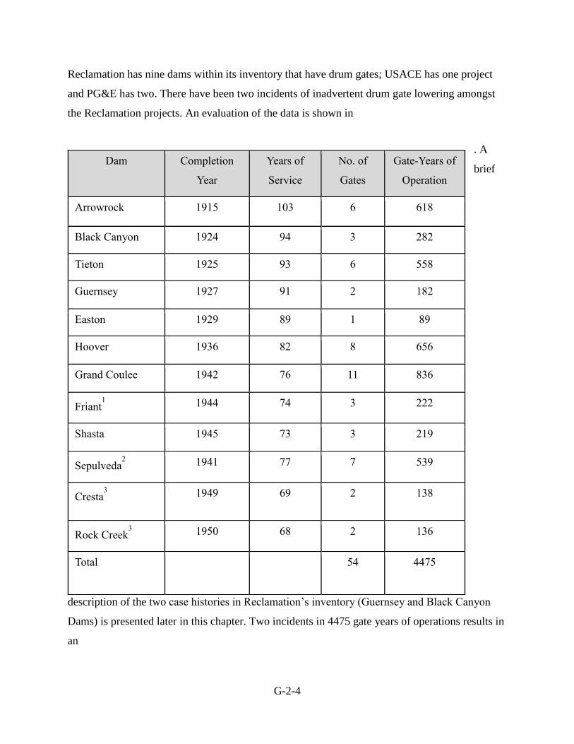
Reclamation has nine dams within its inventory that have drum gates; USACE has one project
and PG&E has two. There have been two incidents of inadvertent drum gate lowering amongst
the Reclamation projects. An evaluation of the data is shown in
. A
brief
description of the two case histories in Reclamation’s inventory (Guernsey and Black Canyon
Dams) is presented later in this chapter. Two incidents in 4475 gate years of operations results in
an
Dam Completion
Year
Years of
Service
No. of
Gates
Gate-Years of
Operation
Arrowrock 1915 103 6 618
Black Canyon 1924 94 3 282
Tieton 1925 93 6 558
Guernsey 1927 91 2 182
Easton 1929 89 1 89
Hoover 1936 82 8 656
Grand Coulee 1942 76 11 836
Friant1 1944 74 3 222
Shasta 1945 73 3 219
Sepulveda2 1941 77 7 539
Cresta3 1949 69 2 138
Rock Creek3 1950 68 2 136
Total
54 4475

G-2-5
annual probability of a gate problem of about 4.4 x 10⁻⁴.This can be used as a base rate, and
adjustments made up or down, based on key site-specific adverse and favorable factors (see also
section on Building the Case).

G-2-6
Table G-2-1 Summary of Drum Gates
NOTES:
All are USBR projects unless noted otherwise.
1. Two drum gates replaced
2. USACE has Drum Gates at only Sepulveda Dam
3. Pacific Gas & Electric (PG&E) has drum gates at two projects (Cresta Dam and Rock Creek Dam)
Dam Completion
Year
Years of
Service
No. of
Gates
Gate-Years of
Operation
Arrowrock 1915 103 6 618
Black Canyon 1924 94 3 282
Tieton 1925 93 6 558
Guernsey 1927 91 2 182
Easton 1929 89 1 89
Hoover 1936 82 8 656
Grand Coulee 1942 76 11 836
Friant1 1944 74 3 222
Shasta 1945 73 3 219
Sepulveda2 1941 77 7 539
Cresta3 1949 69 2 138
Rock Creek3 1950 68 2 136
Total
54 4475

G-2-7
Obermeyer Gates
Obermeyer gates are composed of steel panels supported by inflatable bladders. Elevation of the
gate is controlled by the air pressure in the bladders and can be adjusted to control pool. These
gates have usually been used under low head conditions. Issues with Obermeyer gates are
usually experienced in areas with heavy ice and debris where puncturing of the inflatable
bladders could occur.
Ring Gates
Ring gates which control morning-glory type spillways can operate according to a similar
concept as drum gates. The ring floats in a circular chamber, and valves let water in and out of
the chamber. A drain line keeps water from collecting within the gate. Gate stops keep the gate
from floating completely out of the chamber. Many of the potential failure mechanisms for drum
gates would also apply to ring gates. The exception might be failure of the hinge pins, as there
are no hinges or hinge pins associated with this type of ring gate. However, there may be some
mechanism whereby the gate could become torqued and stuck in the chamber. This could affect
the ability to release water during a large flood.
Morning glory spillways have other issues related to where the flow is controlled. Although the
design would assure that the flow is controlled at the spillway crest, passing more than the design
flow can result in control transitioning to the “throat”, and extrapolating discharge curves beyond
the design value may not be appropriate, unless the shift to throat control is accounted for. In
addition, debris may be easily lodged in tunnel type spillways (depending on the diameter) in
which case there may be little that can be done to remove the blockage until the flow subsides.

G-2-8
Figure G-2-2 Morning Glory Spillway, Monticello Dam, USBR
Roller Gates
This type of gate is more commonly found in older, low head navigation dams with wide pier to
pier distance. A roller gate is a horizontal steel cylinder spanning between piers, usually riveted.
The cylinder is attached to end disks at each end which bear against inclined racks set into the
side of each pier. To control flow, the gates are raised or lowered in the rack by chains powered
by electric motors in the piers. The primary structural members of the roller gates are outlined
below. Schematic sketches of roller gates are shown in Error! Reference source not found..
1. Drum Assembly. A large cylinder which acts as a beam and torque tube to carry dead and
hydrostatic loads. The skin plate of the drum is stiffened by internal ribs and truss-type
assembly. All loads on the drum are transferred to the end disks.

G-2-9
2. Apron Assembly. Skin plate and truss assembly used to increase the damming surface of
the gate without increasing the diameter of the drum. The drum rotates as the gate is
raised or lower and remain in contact with the spillway crest. The apron can be added to
the bottom or the top of the gate.
3. End Disks. Drum assembly transfers load to end disks which are truss type
configurations.
Figure G-2-3 Sketch of Roller Gates (USACE, 1952)
Submersible roller gates were designed to facilitate flow of ice and debris. Error! Reference
source not found. below shows a cross section of a submersible roller gate.
When evaluating roller gates for a risk assessment, consideration must be given to the original
design and current condition of the gate body. Many gates designed in the 1930’s for locks and
dams on the Mississippi River did not consider additional loading due to ice (Bower, J & et al,
1994) or seismic events. Excessive corrosion and section loss can lead to overstressing of the
members, fatigue cracking and possible unsatisfactory performance of the gate. Fatigue cracking
can be caused by stress concentrations due to poor detailing or weld details added to riveted
structures for repairs or strengthening and excessive vibration of the gate during operation.
Fatigue cracks can usually be found at the location of the repair or at the riveted connections
between components such as the drum cylinder and end shields. The apron is more susceptible to
vibration, so fatigue cracking due to vibration could be found at this location (Bower, J & et al,
1994). Roller gates are built with enough redundancy that fatigue cracking will not usually cause
G-2-10
unsatisfactory performance of the gate body. Riveted structures are generally less susceptible to
fatigue cracking since the components are separated and the cracks will not propagate from one
to component to another. Evaluation of less redundant components, such as the lifting chains and
apron structure, should be done.
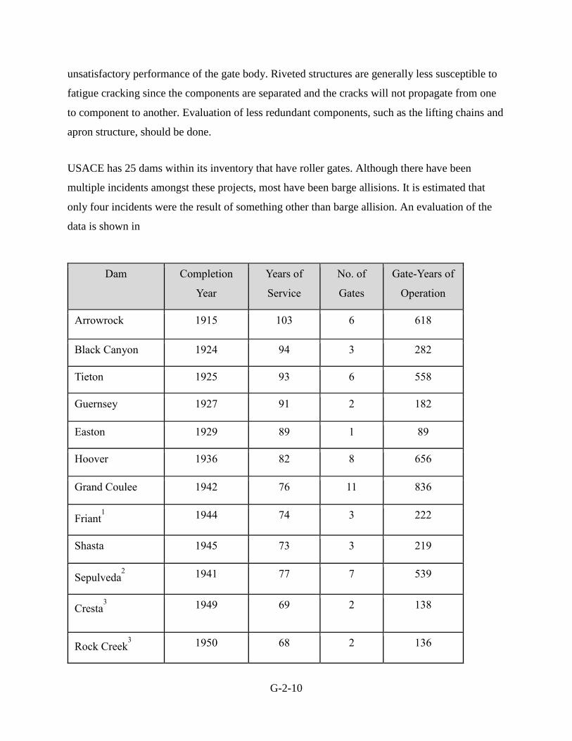
USACE has 25 dams within its inventory that have roller gates. Although there have been
multiple incidents amongst these projects, most have been barge allisions. It is estimated that
only four incidents were the result of something other than barge allision. An evaluation of the
data is shown in
Dam Completion
Year
Years of
Service
No. of
Gates
Gate-Years of
Operation
Arrowrock 1915 103 6 618
Black Canyon 1924 94 3 282
Tieton 1925 93 6 558
Guernsey 1927 91 2 182
Easton 1929 89 1 89
Hoover 1936 82 8 656
Grand Coulee 1942 76 11 836
Friant1 1944 74 3 222
Shasta 1945 73 3 219
Sepulveda2 1941 77 7 539
Cresta3 1949 69 2 138
Rock Creek3 1950 68 2 136

G-2-11
. A
brief
description of one case history is presented later in this chapter. Four incidents in 9401 gate years
of operations results in an annual probability of a gate problem of about 4.2 x 10⁻⁴. This can be
used as a base rate, and adjustments made up or down, based on key site-specific adverse and
favorable factors (see also section on Building the Case).
Figure G-2-4 Cross Section of a Roller Gate, Lock and Dam 14 (USACE, 1936)
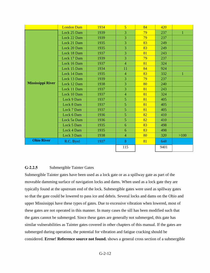
Table G-2-2 Summary of USACE Roller Gates
Waterway/River Dam Name Year
Constructed
# Roller
Gates
Years of
Service
Gate
Years
#
Recorded
Incidents
Kanawha River Winfield Dam 1937 6 81 486 2
Marmet Dam 1934 5 84 420
Total
54 4475
G-2-12
London Dam 1934 5 84 420
Mississippi River
Lock 25 Dam 1939 3 79 237 1
Lock 22 Dam 1939 3 79 237
Lock 21 Dam 1935 3 83 249
Lock 20 Dam 1935 3 83 249
Lock 18 Dam 1937 3 81 243
Lock 17 Dam 1939 3 79 237
Lock 16 Dam 1937 4 81 324
Lock 15 Dam 1934 11 84 924
Lock 14 Dam 1935 4 83 332 1
Lock 13 Dam 1939 3 79 237
Lock 12 Dam 1938 3 80 240
Lock 11 Dam 1937 3 81 243
Lock 10 Dam 1937 4 81 324
Lock 9 Dam 1937 5 81 405
Lock 8 Dam 1937 5 81 405
Lock 7 Dam 1937 5 81 405
Lock 6 Dam 1936 5 82 410
Lock 5a Dam 1936 5 82 410
Lock 5 Dam 1935 6 83 498
Lock 4 Dam 1935 6 83 498
Lock 3 Dam 1938 4 80 320 >100
Ohio River R.C. Byrd 1937 8 81 648
115 9401
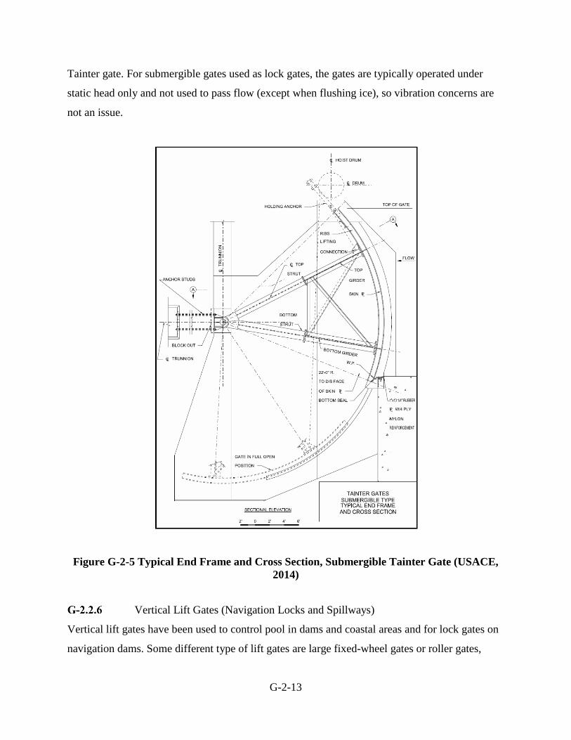
Submergible Tainter Gates
Submergible Tainter gates have been used as a lock gate or as a spillway gate as part of the
moveable damming surface of navigation locks and dams. When used as a lock gate they are
typically found at the upstream end of the lock. Submergible gates were used as spillway gates
so that the gate could be lowered to pass ice and debris. Several locks and dams on the Ohio and
upper Mississippi have these types of gates. Due to excessive vibration when lowered, most of
these gates are not operated in this manner. In many cases the sill has been modified such that
the gates cannot be submerged. Since these gates are generally not submerged, this gate has
similar vulnerabilities as Tainter gates covered in other chapters of this manual. If the gates are
submerged during operation, the potential for vibration and fatigue cracking should be
considered. Error! Reference source not found. shows a general cross section of a submergible
G-2-13
Tainter gate. For submergible gates used as lock gates, the gates are typically operated under
static head only and not used to pass flow (except when flushing ice), so vibration concerns are
not an issue.
Figure G-2-5 Typical End Frame and Cross Section, Submergible Tainter Gate (USACE,
2014)
Vertical Lift Gates (Navigation Locks and Spillways)
Vertical lift gates have been used to control pool in dams and coastal areas and for lock gates on
navigation dams. Some different type of lift gates are large fixed-wheel gates or roller gates,

G-2-14
which are raised and lowered with a hoisting mechanism. Failure of one or more of these large
gates could release water that exceeds the channel capacity or a sudden surge of water that could
surprise recreationists, or in the case of a navigation lock, it could lead to loss of lock service.
For navigation locks, overhead or submergible gates may be used in the lock chambers
especially in those with high heads, such as John Day and Ice Harbor Locks and Dam.
Submergible lift gates are usually used as the upstream gate of a lock where the gate rests below
the upstream sill, as seen in Error! Reference source not found.. Overhead lift gates, as seen in
Error! Reference source not found., are used as the downstream gate of a lock where the lift is
great enough to provide the necessary clearance when the gate is out of the water. This type of
gate requires a tower with overhead cables, sheaves, and bull wheels to support the gate during
operation and counterweights to assist the hoisting machinery. Vertical gates are commonly used
when the space and sufficient support is not available and will not permit the use of miter gates,
or as hurricane or tide gates when the gate may be subject to reverse hydrostatic and
hydrodynamic loading (USACE, 2014).
Vertical lift gates are used as spillway gates when the amount of head on the gate would require
an exceedingly large pier to support a Tainter gate, therefore providing a more economical
design.

G-2-15
Figure G-2-6 Submergible Vertical Lift Gate (USACE, 2006)
G-2-16
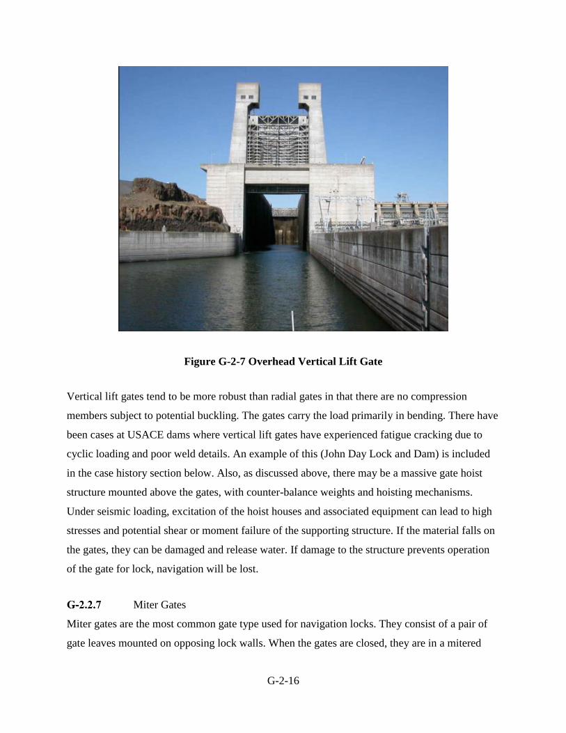
Figure G-2-7 Overhead Vertical Lift Gate
Vertical lift gates tend to be more robust than radial gates in that there are no compression
members subject to potential buckling. The gates carry the load primarily in bending. There have
been cases at USACE dams where vertical lift gates have experienced fatigue cracking due to
cyclic loading and poor weld details. An example of this (John Day Lock and Dam) is included
in the case history section below. Also, as discussed above, there may be a massive gate hoist
structure mounted above the gates, with counter-balance weights and hoisting mechanisms.
Under seismic loading, excitation of the hoist houses and associated equipment can lead to high
stresses and potential shear or moment failure of the supporting structure. If the material falls on
the gates, they can be damaged and release water. If damage to the structure prevents operation
of the gate for lock, navigation will be lost.
Miter Gates
Miter gates are the most common gate type used for navigation locks. They consist of a pair of
gate leaves mounted on opposing lock walls. When the gates are closed, they are in a mitered

G-2-17
position, forming a shallow three hinged arch, with the arch pointing in the upstream direction.
When the gates are opened, they are recessed into the lock wall. Miter gates are designed to be
vertically or horizontally framed, although horizontally framed gates are more commonly found
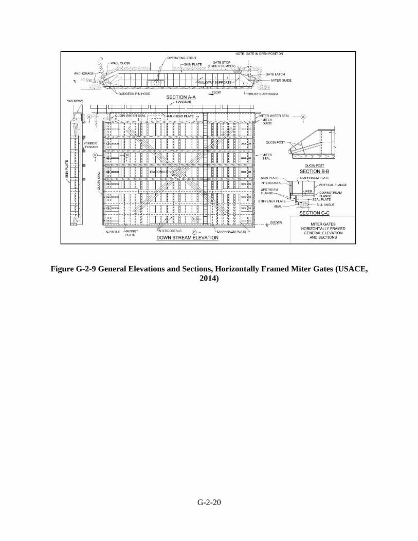
in the USACE inventory. Horizontally framed gates (Figure G-2-9) consist of a series of
horizontal girders that are framed together with vertical diaphragms, composed of welded plate
sections, with skin plate attached to the upstream flanges. Each horizontal member is supported
by the vertical quoin post on one end and the miter post at the other end. Vertical framed gates
(Figure G-2-10) consist of vertical beams that span from a horizontal girder at the sill to a
horizontal girder at the top of the gate. The horizontal girders transfer the load to the miter and
the quoin at the top and into the sill at the bottom of the gate. Vertically framed miter gates are
usually used in locks with height to width ratio less than 0.5 (USACE, 2014). Since the vertically
framed miter gates rely on the concrete sill, the condition of the sill should also be assessed if
this type of gate is present.
The main structural issues encountered in miter gates are due to the cyclic loading it experiences
during lock operation. Fatigue cracking on horizontally framed miter gates has been experienced
at a number of dams within USACE. Fatigue cracking occurs due to the stress reversal occurring
at the welded connections where stress concentrations and/or residual tensile stresses are present.
During operation, loads on the gates are carried through compression, creating a load reversal at
these locations, which are exacerbated by the geometric configuration of the welds. In many
cases, it has been found that the cracking extends well beyond the weld zone into the base metal
of the flanges. This type of cracking is often wide spread since the gate is designed to carry the
load through the entire gate structure but is most commonly found near the lower girders near the
quoin and miter ends (USACE, June 2010). Although miter gates are redundant structures, if the
cracks are not repaired, they could lead to structural failure of the gate due to buckling or
excessive gate movement during mitering. These issues can be worsened by excessive corrosion
of the girders. The most severe corrosion generally occurs between upper and lower pool and
near the water line where galvanic protection has limited effect and the paint system is damaged
by debris and barge impact. There have been numerous examples of unscheduled and extended
lock closures for emergency repairs of the miter gates due to fatigue cracking.

G-2-18
Other components of the gate are also subject to cyclic loading and have experienced fatigue
cracking as well. Failure of the gudgeon anchor arm has occurred due to fatigue cracking. Since
the miter gates are designed to transfer load to the quoin blocks on the wall, the anchor arms are
generally only designed to take the operating load of the gate weight as it is opened or closed. As
the quoin blocks are worn down over time, more load is transferred to the pintle and anchor
arms, increasing the stress range of the anchor arms. Cracks usually start at welded connections
due to weld discontinuity and poor weld details. Failure of the embedded anchorage can also
occur due to poor weld details and extensive corrosion of the members and the inability to detect
corrosion and cracking or access them for repair or replacement.
Cracking has also been found in the flanges where the pintle casting is connected or in the pintle
socket casting itself. Cracking in the flanges can cause excessive movement of the pintle, which
could result in problems during operation of the gates. Cracking of the pintle socket casting is
usually caused by worn or improper adjustment of quoin blocks resulting in loss of contact with
the wall quoin. This results in additional load on the pintle, which can lead to cracking of the
pintle or failure of the bolts at the girder connection (USACE, June 2010). Figure G-2-8 shows
cracking around the pintle casting discovered at Greenup Locks and Dam in September 2003.
Figure G-2-8 Cracking in Main Chamber Miter Gates, Greenup Lock and Dam (USACE,
May 2010)
G-2-19
Since miter gates are designed to take all differential hydrostatic loading through arching action,
it is critical that the gates are properly mitered before the chamber is filled. Additionally, the
anchor arms are only designed for the weight of the gates leaves, and the operating machinery is
only designed to move the gates through static water. Therefore, there should be very limited
flow through the chamber when the gates are operated. This means that miter gates are
particularly susceptible to operational failures. Miter gates are also susceptible to failure from
barge impacts. See Chapter VIII-1 for more information on these types of failure modes.
Evaluation of the miter gates under seismic loading should also be considered if seismic loading
is considered during the risk assessment. A brief description of the two case histories in the
Corps’ inventory (Markland and Greenup Locks and Dams) is presented later in this chapter.
USACE has over 150 navigation locks within its inventory that have miter gates. There have
been many hundreds of incidents amongst these projects, most being the result of barge allisions.
Because data has never been summarized for all projects, there is no reliable base incident rate
available.
G-2-20
Figure G-2-9 General Elevations and Sections, Horizontally Framed Miter Gates (USACE,
2014)

G-2-21
Figure G-2-10 General Plan and Elevation, Vertically Framed Miter Gates (USACE, 2014)
Sector Gates
Sector gates are used in coastal areas, where the lock or canal may be subjected to head reversal
due to tidal range or storm surge. The gate consists of two leaves that join at the center to create
the damming surface and recess into the lock wall when open. The advantage of using sector
gates is that they can be loaded from either direction and can be opened and closed under small
differential heads, or with flow through the lock. Additionally lock structures with sector gates
do not need culverts or culvert valves, as the lock chamber is raised or lowered by simply
cracking open the sector gates. Sector gates are generally used for locks with differential head of
15 feet or less. Figure G-2-11 shows a general plan and cross section of a Sector gate.
As in the evaluation of other gates types, vulnerabilities include overstressing due to additional
loading than what the gate was designed for, including hydrologic and seismic loads. Evaluation
of the anchorage into the lock wall shall also be assessed for movement, section loss, cracks at
welded connections, etc. Many sector gates cannot be easily dewatered due to the configuration

G-2-22
of their lock chambers (i.e. no bulkhead slots) in conjunction with the high traffic demand
associated with them. Because sector gates are typically so large, special high capacity cranes are
generally required to remove them from their recesses to permit detailed inspections and repair.
Thus corrosion of submerged structural members can be a typical problem.
Figure G-2-11 General Plan and Section of a Sector Gate (USACE, 2014)
Outlet Works and Penstocks
Outlet works and penstocks tend to generally be operated frequently to release water, and failure
of the conduits or gates would typically not release enough water to result in life-threatening
flows. However, there may be a case where the outlet works or penstocks have enough capacity
to release life-threatening flows. In these cases the gate mechanisms should be reviewed for
vulnerabilities. In addition, exposed penstocks or conduits can be subject to high bending
stresses during earthquake loading, especially when full of water, potentially resulting in pipe
rupture. However, in many cases, the outflows could be limited by the size of the rupture.
G-2-23
Culvert Valves – Lock Filling/Emptying System
Reverse Tainter valves are the most common valve type in USACE navigation locks. Reverse
Tainter valves differ from Tainter Gates in that the trunnion is located upstream of the gate and
the skin plate faces the downstream direction. The gate has a “reverse” orientation from the
Tainter gates used in dam spillways. Cracks in the reverse Tainter gates have been found in the
radial ribs and welds due to vibration caused by high velocity water flow and cyclic loading due
to normal operation of the lock. Depending on the design of the filling and emptying system, a
failure of this valve may not cause a loss of service. If there are two filling and emptying
systems, the damaged gate can be placed out of service without losing the capacity to operate. If
there is no redundancy in the system, then a loss of service of the lock will need to be evaluated.
A brief description of the USACE Cannelton Lock and Dam valves is presented later in this
chapter.
G-2.3 Event Trees
For other types of potential failure modes related to gates, the development of event trees follows
the same procedure as previously described in this manual. First, the potential failure modes are
identified and described fully from initiation, through step by step progression, to the breach
mechanism for uncontrolled release of reservoir water or loss of service. Then, based on this
description, an event tree is developed (see section on Event Trees). It is not possible to show
examples for every type of potential failure mechanism associated with gates or valves, and it is
incumbent on the risk estimating team to look at each case and determine if there are potentially
significant risk contributors. If there are, the potential failure modes and event trees should be
developed for these cases.
The following are examples of potential failure mode descriptions:
Failure of a Drum Gate under Seismic Loading:
With the reservoir high on the drum gates, a large earthquake occurs at the site that causes
large seismic response and cracking through the unreinforced concrete near the base of the
upstream float chamber walls. Additional cracking separates the upstream walls from the
side walls. The upstream walls with gates still attached at the hinge pin, move into the float
chambers. Buoyant forces are sufficient to displace the gates and attached concrete to the

G-2-24
point where the gate is no longer effectively retaining water. Failure of one or more gates
exceeds the safe downstream channel capacity.
The event tree developed from this description is shown in Error! Reference source not found..
Only one branch has been fully developed for illustration purposes.
Structural evaluation of reinforced concrete supporting structure for gates is similar to that
already described (refer to the section on Reinforced Concrete Fragility). Hydrodynamic loading
must consider the structural response if the gates sit atop a tall concrete structure. Estimating the
chance that a gate and the attached concrete would be displaced enough to render the gate
ineffective would consider the buoyant forces and likely flow velocity through the damaged gate
opening, and the geometry of the opening relative to the gate geometry, but ultimately would be
a judgment call (see section on Subjective Probability and Expert Elicitation). Each branch of the
tree can be estimated for a single gate failure, and then the likelihood of multiple gates failing
can be estimated using Pascal’s Triangle, as described in the section on Seismic Failure of
Spillway Radial Gates.
Miter Gate Failure Due to Fatigue Cracking:
The main and secondary members of the downstream miter gate have section loss due to
corrosion and experienced fatigue cracks. Fatigue cracks continue to form at the welded
joints between the horizontal girders and the quoin or miter posts or the welded joints of
the diagonal gusset plates. The fatigue cracks are caused by the lock cycles, cycling of
residual stresses in the welds, temporal loads, loss of diagonal stress, and impact
loadings from tows. The fatigue cracks form and are undetected due to their small size,
infrequent inspections, or being hidden by water, corrosion, silt, or debris; therefore,
intervention is unsuccessful. The fatigue cracks propagate through one or more main
structural members and cause localized failure of the main structural member(s). Failure
of a main structural member (horizontal girder, quoin post, miter post, or diagonal
gusset plate) renders the miter gate inoperable and results in a lock closure and
disruption to navigation traffic (USACE, 2013).
G-2-25
G-2.4 Consequences
For flood control dams, consequences are evaluated by estimating incremental life loss due to the
dam breach. Consequences will be a function of the reservoir level at the time of failure (which
determines the breach outflow). Loss of life can be estimated from these breach outflows and the
estimated population at risk that would be exposed to the breach outflows, using the procedures
outlined in the section on Consequences of Dam Failure and the section on Seismic Failure of
Spillway Radial Gates.
Failure of a navigation dam can be defined as breach of the damming surface or artificial raising
of pool due to spillway blockage. This could lead to inundation of individuals downstream (high
hazard dams only); overtopping of upstream control structures such as levees due to the artificial
raise of pool, leading to inundation; or loss of pool leading to loss of navigation, hydropower
generation, municipal/industrial water intakes, etc. Life loss consequences due to downstream
inundation shall be evaluated for high hazard locks and dams or when the failure modes lead to
life loss in all navigation dams (i.e. upstream inundation or project/navigation industry
personnel). Economic consequences due to failure of a navigation lock and dam shall be
evaluated when the failure mode does not lead to life loss. Some of the economic damages to
consider include:
Impacts due to loss of service/navigation, including the navigation industry when the
lock(s) is out of service or municipal/industrial water intakes when pool is lost.
Downstream property flood damage when releases due to a dam breach exceed
downstream channel capacity.
Upstream property flood damage when there is an artificial rise or lowering of the pool.
Loss of hydropower generation.
Emergency repairs to get the project back in service.
Navigation Transit Delay Cost tables are available through the Navigation Planning Center of
Expertise to estimate economic damages due to loss of service. The table includes navigation
delay costs for consecutive number of days that all lock projects in the USACE inventory are
unavailable for service. Economic impacts due to loss of navigation should only consider
G-2-26
unscheduled closures of the lock(s). The Navigation Transit Delay Cost tables assume all
closures are unscheduled and are available for both full and partial closures; where a full closure
includes both lock chambers, and a partial closure only considers closure of the main chamber. If
a failure mode only affects the auxiliary chamber, economic impacts are generally assumed to be
minimal. When using these tables, consideration should be given to the date of publication and
what potential changes may have occurred since publication (e.g. change in local industry,
inflation, etc.).
When evaluating consequences due to a gate failure at a project, consideration should be given to
the availability of stop logs that can be set under flowing conditions. These could have
significant affects in consequence estimates.
G-2.5 Accounting for Uncertainty
The method of accounting for uncertainty in seismic loading is described in the section on Event
Trees. Typically, the reservoir elevation exceedance probabilities are taken directly from the
historical reservoir operations data, which do not account for uncertainty. Uncertainty in the
failure probability and consequences are accounted for by entering the estimates as distributions
(as describe above) rather than single point values. A “Monte-Carlo” simulation is then run to
display the uncertainty in the estimates, as described in the section on Combining and Portraying
Risks. As with all potential failure modes, parametric or sensitivity studies are key to
understanding the risk uncertainty. The rank sensitivity coefficients from @Risk can be used to
get a handle on which parameters affect the risk the most. Varying the distributions associated
with these parameters within reasonable possibilities can provide insight as to how the risks
might change with different input. The possible need for additional information to tighten the
estimates for critical parameters can then be evaluated.
G-2.6 Relevant Case Histories
Guernsey Dam Drum Gates
One of two drum gates at the south (right) spillway of Guernsey Dam inadvertently opened in
1986. A painting contractor left trash within the gate which eventually plugged the drain line.
The interior of the gate filled with water and the gate lost buoyancy. The gate lowered about half
way in seven hours before the problem was recognized and the trash cleared from the drain line.

G-2-27
Although the downstream discharge increased significantly, the downstream channel capacity
was never exceeded and there were no injuries or fatalities (Graham and Hilldale, 2001).
Black Canyon Diversion Dam Drum Gates
Extension plates were added to the gates to raise the lake level twice (in 1952 and 1998). During
the week of December 15, 1998 during routine exercising of the drum gates, Gate No. 3 was
lowered about 1.5 feet, but attempts to raise the gate failed. The gate was lowered another 6
inches, but again could not be raised from that position. The reservoir was lowered and it was
found that drain line nipple had come unthreaded from the swivel joint. The gate did not sink
entirely because a check valve closed or the drain line on the other end of the gate passed enough
water to maintain equilibrium. In 2001, it was discovered that 13 of the 17 hinge pins in Gate
No. 3 were fractured. (Only one hinge pin in each of the other two gates was found to be
fractured.) The bushings were re-bored, re-aligned and the pins were replaced.
Cresta Dam Drum Gates, California
Cresta Dam is located on the North Fork of the Feather River, and is a key feature in PG&E’s
Feather River hydroelectric system. The dam forms the forebay for Cresta Powerhouse and was
constructed in 1949. There are two 124-foot long by 28-foot high drum gates at the top of Cresta
Dam. Drum gates at Cresta Dam are raised to maintain the reservoir level for electric power
generation at the Cresta Powerhouse under normal operations and operated to regulate spills
during high river flow conditions. On July 5, 1997, the left drum gate at Cresta Dam began to
drop uncontrollably. The gate took about 20 to 30 minutes to completely lower. The downstream
water level rose from 1.59 feet to 15 feet in approximately 40 minutes. The maximum recorded
downstream discharge was 15,140 ft3/s. No injuries or fatalities occurred as a result of the gate
failure.
The left drum gate at Cresta Dam dropped primarily due to a combination of failure of the drum
gate drain line and leakage into the drum gate. Failure of the drum gate drain line was likely
caused by crimping of the drain line at the downstream stop seal. Water accumulated in the drum
gate due to leakage through the check valves as a result of failure of the drum gate drain lines
and normal leakage into the drum gate through connections, hatches and the gate skin (Pacific
Gas & Electric Company, 1997).

G-2-28
Markland Lock and Dam Miter Gate Fatigue Cracking
A dewatering was scheduled for the main chamber at Markland Locks and Dam in 1994 to
perform major maintenance including jacking the miter gates and replacing the pintle and seals.
Once the lock was dewatered and the gates were inspected, severe cracking was found in some
of the welds of the horizontal girders. In particular, the heaviest cracking occurred near the pintle
area on the lower girders. It was determined that the extensive cracking was fatigue-related and
additional finite element analysis was done to help determine the cause for the extensive
cracking. Through the additional analysis, it was determined that the cracking was due to
residual tensile stresses present near the girder welds. When welding occurs during original
construction, large stresses are developed in the members near the weld joints. During operation
of the gate, the members are subjected to compression loads, causing a stress reversal a these
locations. Since the gates were considered to be in critical condition, immediate repairs were
made to the gate during the dewatering. This included gouging out the cracks and rewelding. To
evaluate the performance of the repairs, another dewatering was scheduled in 1996 It was found
that the cracks had re-initiated at the same locations where they had been repaired during the
1994 dewatering. Other modifications were made to the gate during the dewatering of 1996
including adding structural plates, etc, but the condition of the gate was still considered critical.
Louisville District Operations and Engineering Divisions instituted a 2-3 year dewatering
interval to continue to monitor the gates until the gates were replaced (USACE, 1999).
Figure G-2-12 Fatigue cracking in girder flange at diagonal anchor plate, Markland Lock
and Dam (USACE, June 2010)

G-2-29
Greenup Locks and Dam Anchor Arm Failure
The emergency closure of Greenup Locks and Dam main chamber took place from Wednesday,
27 January through Monday, 22 February 2010. The closure resulted from a sudden fatigue
failure of the miter anchor arm on the main chamber downstream middle wall gate leaf. The gate
was being properly operated during a routine up bound lockage. No operator error occurred.
The failure initiated at the root of a fillet weld connecting the miter anchor arm to the top
connecting link and propagated through the entire cross section of the miter anchor arm. The
weld was shown on the original contract drawings and had been identified during Periodic
Inspection No. 8 performed in July 2008 as a poor weld detail for a tension member. Visual
inspection of the root of the weld and base material subsequent to failure indicates the crack had
initiated prior to the failure as evidenced by corrosion in the crack. The crack was not visible
during prior inspections due to limited accessibility, paint and over spill of lubricating grease for
the gudgeon pin.
The gate came to rest on the concrete sill in a near vertical position supported by the pintle, strut
arm and the remaining non fractured but damaged recess anchor arm. Emergency repairs were
performed on January 29, 2010 by welding a splice plate to the fractured anchor arm and other
gate stabilization efforts were completed to prevent more damage to the gate. The miter gate was
removed and a detailed structural inspection was performed on the gate and anchorage. Dive
inspections were performed on the gate sill and pintle. Anchor wedge assemblies, anchor arms,
connector plates, gudgeon and link pins were replaced and the gate was reinstalled on February
21, 2010. A final inspection was done on February 22, 2010 and the main lock chamber was
reopened for traffic (USACE, May 2010).

G-2-30
Figure G-2-13 Failed Anchor Arm, Greenup Lock and Dam (USACE, May 2010)
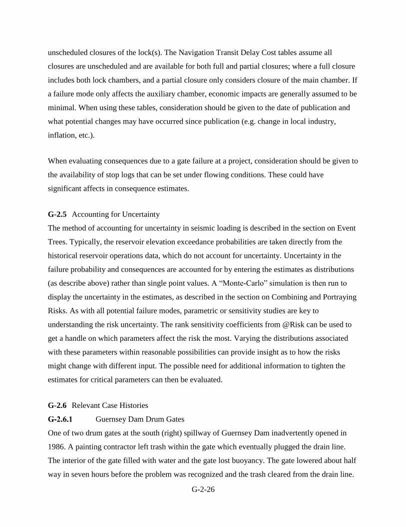
Cannelton Locks and Dam Culvert Valve Failure
The lower river wall emptying culvert valve for the main chamber at Cannelton Locks and Dam
was reported to be inoperable on September 10, 1999. The valve emergency bulkheads were set
by lock personnel, but extensive leakage prohibited immediate dewatering of the valve
chamber. The Louisville Repair Station (LRS) arrived at the site early in the week of 4 October
and were able to get the bulkheads set and the chamber pumped down so that the valve could be
inspected and removed for repairs. The initial inspection was performed on Wednesday, 6 October
1999. The valve was inspected in-situ in the valve chamber. The valve was bound against the
sidewalls and had a slight twist in a clockwise direction as viewed facing downstream. The skin
plate and vertical rib beams were torn away from the lower girder. The fillet welds that attached
the rib beams to the lower girder had failed. The second and third vertical rib beams were fractured
completely through the flange and extended through the web, and proceeded to tear the stem of
the T-beam away from the skin plate. These beams had also broken loose from the upper girder.
The end vertical rib beam nearest the Kentucky side suffered a fractured web. The downstream
flanges of both of these girders experienced warping when the rib beams tore away. The culvert
valve was removed and inspected more closely and it was found that the main valve body was
considered structurally sound and deemed capable of service. The failure of the valve may be
attributed to fatigue of the welds which connect the rib T-beams to the lower girder beam of the
G-2-31
main valve frame. Cannelton's 1200 foot chamber has experienced a significant number of
open/close cycles in its 30 year career; this is categorized as low cycle fatigue loading. In addition
to the low cycle static loading imparted by differential hydraulic head, the valve also experienced
high cycle fatigue due to turbulent flow conditions (USACE, October 1999).
Figure G-2-14 Failed Culvert Valve, Cannelton Locks and Dam
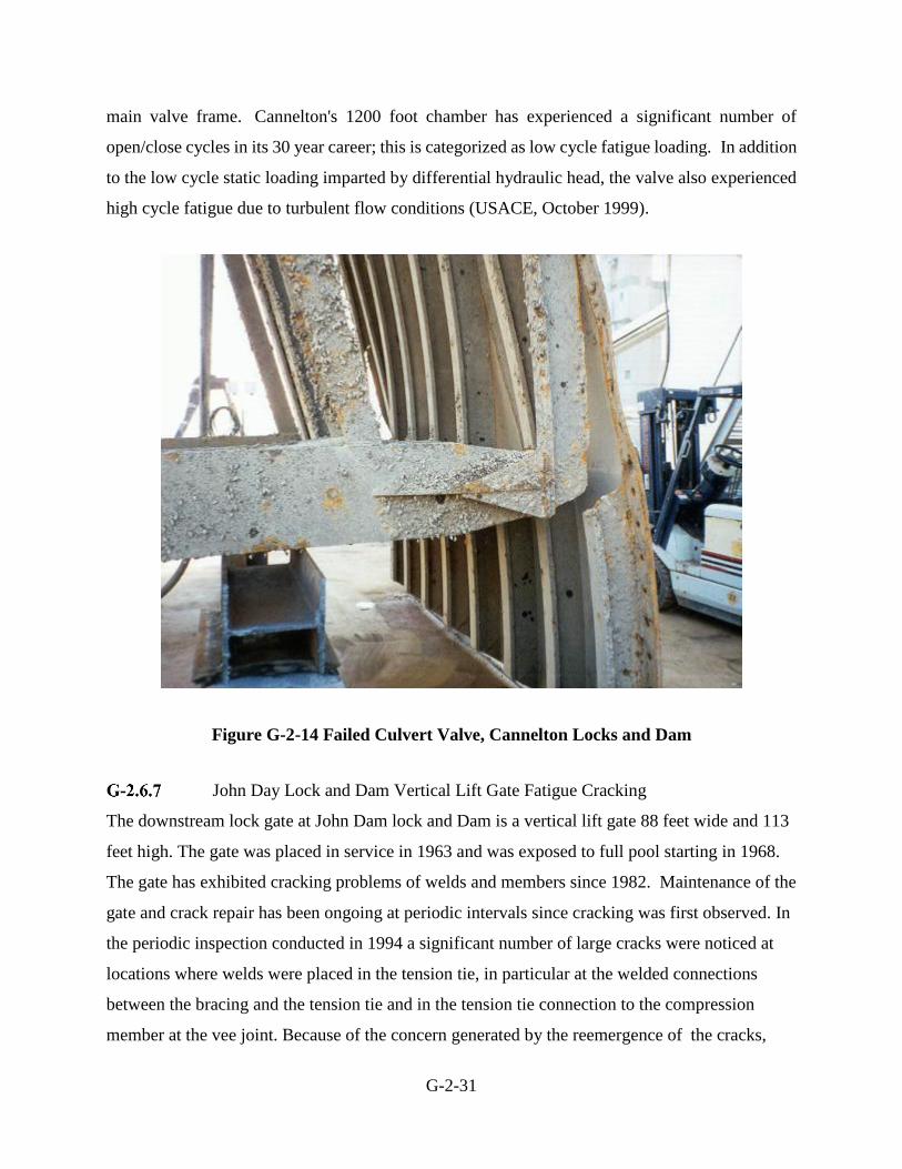
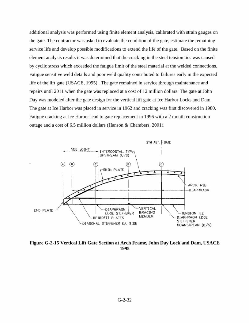
John Day Lock and Dam Vertical Lift Gate Fatigue Cracking
The downstream lock gate at John Dam lock and Dam is a vertical lift gate 88 feet wide and 113
feet high. The gate was placed in service in 1963 and was exposed to full pool starting in 1968.
The gate has exhibited cracking problems of welds and members since 1982. Maintenance of the
gate and crack repair has been ongoing at periodic intervals since cracking was first observed. In
the periodic inspection conducted in 1994 a significant number of large cracks were noticed at
locations where welds were placed in the tension tie, in particular at the welded connections
between the bracing and the tension tie and in the tension tie connection to the compression
member at the vee joint. Because of the concern generated by the reemergence of the cracks,
G-2-32
additional analysis was performed using finite element analysis, calibrated with strain gauges on
the gate. The contractor was asked to evaluate the condition of the gate, estimate the remaining
service life and develop possible modifications to extend the life of the gate. Based on the finite
element analysis results it was determined that the cracking in the steel tension ties was caused
by cyclic stress which exceeded the fatigue limit of the steel material at the welded connections.
Fatigue sensitive weld details and poor weld quality contributed to failures early in the expected
life of the lift gate (USACE, 1995) . The gate remained in service through maintenance and
repairs until 2011 when the gate was replaced at a cost of 12 million dollars. The gate at John
Day was modeled after the gate design for the vertical lift gate at Ice Harbor Locks and Dam.
The gate at Ice Harbor was placed in service in 1962 and cracking was first discovered in 1980.
Fatigue cracking at Ice Harbor lead to gate replacement in 1996 with a 2 month construction
outage and a cost of 6.5 million dollars (Hanson & Chambers, 2001).
Figure G-2-15 Vertical Lift Gate Section at Arch Frame, John Day Lock and Dam, USACE
1995

G-2-33
Figure G-2-16 Fatigue Cracking in Tension Tie, Vertical Lift Gate, John Day Locks and
Dam (Hanson & Chambers, 2001)
Mississippi River L&D 25 Roller Gate Incident
The emergency repair of a roller gate at Mississippi River Dam 25 took place as a result of an
incident in April 2010. The incident resulted from a limit switch failure. During a routine gate
raising operation as the river was rising to a level in which all gates were being fully raised, the
upper limit switch gear of one of the project’s three 109-foot long roller gates moved out of its
shaft, which prevented it from turning. As a result, the chain hoisted the gate all the way up to
the point at which the hoist chain connection was ripped out of the gate, resulting in heavy
damage to no fewer than five chain lug plates. It was believed that no operator error occurred.
The gate came to rest at an angle with the cog/hoist end up into the bottom of the machinery
house. Emergency repairs began immediately by installing emergency stoplogs to stop flow.
Damage was severe enough that engineers decided the gate had to be completely removed in
order to implement complete repairs. Removing the gate required multiple attempts with various
rigging arrangements. The clear distance from pier to pier is 100 feet; with a gate length of 109
feet, the gate would not clear the pier house. This was the first time a roller gate had ever been
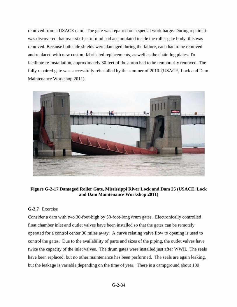
G-2-34
removed from a USACE dam. The gate was repaired on a special work barge. During repairs it
was discovered that over six feet of mud had accumulated inside the roller gate body; this was
removed. Because both side shields were damaged during the failure, each had to be removed
and replaced with new custom fabricated replacements, as well as the chain lug plates. To
facilitate re-installation, approximately 30 feet of the apron had to be temporarily removed. The
fully repaired gate was successfully reinstalled by the summer of 2010. (USACE, Lock and Dam
Maintenance Workshop 2011).
Figure G-2-17 Damaged Roller Gate, Mississippi River Lock and Dam 25 (USACE, Lock
and Dam Maintenance Workshop 2011)
G-2.7 Exercise
Consider a dam with two 30-foot-high by 50-foot-long drum gates. Electronically controlled
float chamber inlet and outlet valves have been installed so that the gates can be remotely
operated for a control center 30 miles away. A curve relating valve flow to opening is used to
control the gates. Due to the availability of parts and sizes of the piping, the outlet valves have
twice the capacity of the inlet valves. The drum gates were installed just after WWII. The seals
have been replaced, but no other maintenance has been performed. The seals are again leaking,
but the leakage is variable depending on the time of year. There is a campground about 100

G-2-35
yards downstream of the dam adjacent to the right river bank. In groups of two to four, discuss
the possible vulnerabilities of the gates.

G-2-36
Figure G-2-18 Example Event Tree for Seismic Failure of Drum Gate Wall

G-2-37
G-2.8 References
Bower, J & et al, “Structural Evaluation of Riveted Spillway Gates”, Technical Report REMR-
CS-43, USACE Waterways Experiment Station, June 1994.
Graham, W.J. and R.C. Hilldale, “Spillway Gate Failure or Misoperation: Representative Case
Histories,” Report DSO-01-01, Bureau of Reclamation, Denver, CO, September 2001.
Hanson, Matthew and Chambers, Donald, “John Day Navigation Lock Downstream Lift Gate
Fatigue Evaluation and Solutions”, USACE infrastructure Conference, August 2001
Pacific Gas & Electric Company, “Investigation of Uncontrolled Operation, Highway Side Drum
Gate, Cresta Dam,” Hydro Generation Department, Analysis Group, July 31, 1997.
Rantz, S.E & et al., “Measurement and Computation of Streamflow: Volume II Computation of
Discharge”, Geological Survey Water-Supply Paper 2175, USGS, 1982.
USACE, “Lock and Dam No. 14”, As-built Drawings, Rock Island, IL, 1936
USACE, “John Day Navigation Lock Downstream Lift Gate”, INCA Engineering Inc, April
1995.
USACE, “Miter Gate Evaluation Summary, Markland Locks and Dam”, Louisville District
Internal Documentation, 1999
USACE, “Cannelton 1200’ Chamber Culvert Valve Failure”, Louisville District Memorandum
for Record, October 1999.
USACE, “Hydraulic Design of Navigation Locks”, EM 1110-2-1604, May 2006.

G-2-38
USACE, “After Action Review for Greenup Locks and Dam, Downstream Middle Wall Miter
Gate, Miter Anchor Arm Failure, 27 January – 22 February 2010”, Memorandum of Record,
May 2010.
USACE, “Advanced Reliability Analysis of Fatigue Cracking in Horizontally Framed Miter
Gates”, ETL 1110-2-566, June 2010.
USACE, “David D. Terry Lock and Dam, Periodic Assessment Report No. 01”, Little Rock
District, October 2014.
USACE, “Design of Hydraulic Steel Structures”, ETL 1110-2-584, June 2014.
Warnock, J.E., "Cavitation Experience of the Bureau of Reclamation," Presented at the Annual
Meeting of the American Society of Civil Engineers, 1944.
USACE, “Lock 25 Roller Gate Repairs”, presented at the 2011 Lock and Dam Maintenance
Workshop.