CHAPTER 18freeit.free.fr/Knovel/Structural and Stress Analysis... · 2005-03-24 · CHAPTER 18...
27
CHAPTER 18 Structural Instability So far, in considering the behaviour of structural members under load, we have been concerned with their ability to withstand different forms of stress. Their strength, therefore, has depended upon the strength properties of the material from which they are fabricated. However, structural members subjected to axial compressive loads may fail in a manner that depends upon their geometrical properties rather than their material properties. It is common experience, for example, that a long slender structural member such as that shown in Fig. 18.l(a) will suddenly bow with large lateral displacements when subjected to an axial compressive load (Fig. 18.1(b)). This phenomenon is known as instability and the member is said to buckle. If the member is exceptionally long and slender it may regain its initial straight shape when the load is removed. Structural members subjected to axial compressive loads are known as columns or struts, although the former term is usually applied to the relatively heavy vertical members that are used to support beams and slabs; struts are compression members in frames and trusses. It is clear from the above discussion that the design of compression members must take into account not only the material strength of the member but also its stability against buckling. Obviously the shorter a member is in relation to its cross- sectional dimensions, the more likely it is that failure will be a failure in compression of the material rather than one due to instability. It follows that in some intermediate range a failure will be a combination of both. We shall investigate the buckling of long slender columns and derive expressions for the buckling or critical load; the discussion will then be extended to the design Fig. 18.1 Buckling of slender column
-
Upload
nguyenkhanh -
Category
Documents
-
view
213 -
download
0
Transcript of CHAPTER 18freeit.free.fr/Knovel/Structural and Stress Analysis... · 2005-03-24 · CHAPTER 18...
CHAPTER 18
Structural Instability
So far, in considering the behaviour of structural members under load, we have been concerned with their ability to withstand different forms of stress. Their strength, therefore, has depended upon the strength properties of the material from which they are fabricated. However, structural members subjected to axial compressive loads may fail in a manner that depends upon their geometrical properties rather than their material properties. It is common experience, for example, that a long slender structural member such as that shown in Fig. 18.l(a) will suddenly bow with large lateral displacements when subjected to an axial compressive load (Fig. 18.1 (b)). This phenomenon is known as instability and the member is said to buckle. If the member is exceptionally long and slender it may regain its initial straight shape when the load is removed.
Structural members subjected to axial compressive loads are known as columns or struts, although the former term is usually applied to the relatively heavy vertical members that are used to support beams and slabs; struts are compression members in frames and trusses.
It is clear from the above discussion that the design of compression members must take into account not only the material strength of the member but also its stability against buckling. Obviously the shorter a member is in relation to its cross- sectional dimensions, the more likely it is that failure will be a failure in compression of the material rather than one due to instability. It follows that in some intermediate range a failure will be a combination of both.
We shall investigate the buckling of long slender columns and derive expressions for the buckling or critical load; the discussion will then be extended to the design
Fig. 18.1 Buckling of slender column
608 Structural Instability
of columns of any length and to a consideration of beams subjected to axial load and bending moment.
18.1 Euler theory for slender columns The first significant contribution to the theory of the buckling of columns was made in the eighteenth century by Euler. His classical approach is still valid for long slender columns possessing a variety of end restraints. Before presenting the theory, however, we shall investigate the nature of buckling and the difference between theory and practice.
We have seen that if an increasing axial compressive load is applied to a long slender column there is a value of load at which the column will suddenly bow or buckle in some unpredetermined direction. This load is patently the buckling load of the column or something very close to the buckling load. The fact that the column buckles in a particular direction implies a degree of asymmetry in the plane of the buckle caused by geometrical and/or material imperfections of the column and its load. Theoretically, however, in our analysis we stipulate a perfectly straight, homogeneous column in which the load is applied precisely along the perfectly straight centroidal axis. Theoretically, therefore, there can be no sudden bowing or buckling, only axial compression. Thus we require a precise definition of buckling load which may be used in the analysis of the perfect column.
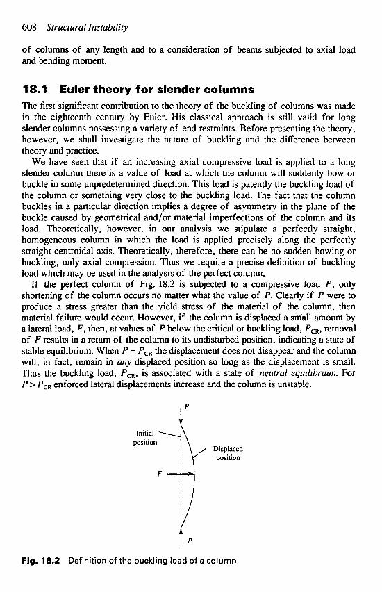
If the perfect column of Fig. 18.2 is subjected to a compressive load P, only shortening of the column occurs no matter what the value of P. Clearly if P were to produce a stress greater than the yield stress of the material of the column, then material failure would occur. However, if the column is displaced a small amount by a lateral load, F , then, at values of P below the critical or buckling load, PCR, removal of F results in a return of the column to its undisturbed position, indicating a state of stable equilibrium. When P = P,, the displacement does not disappear and the column will, in fact, remain in any displaced position so long as the displacement is small. Thus the buckling load, P,,, is associated with a state of neutral equilibrium. For P > P,, enforced lateral displacements increase and the column is unstable.
Fig. 18.2 Definition of the buckling load of a column
Euler theory for slender columns 609
Buckling load for a pin-ended column
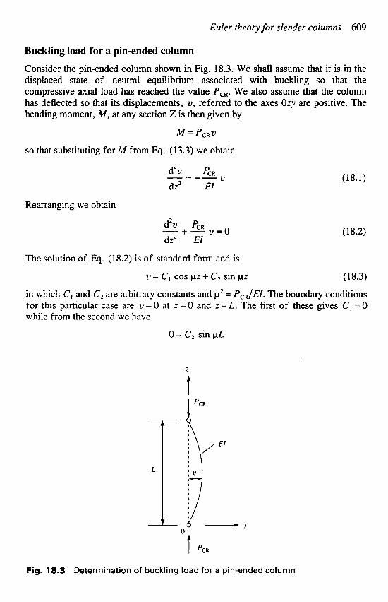
Consider the pin-ended column shown in Fig. 18.3. We shall assume that it is in the displaced state of neutral equilibrium associated with buckling so that the compressive axial load has reached the value PcR. We also assume that the column has deflected so that its displacements, u, referred to the axes Ozy are positive. The bending moment, M, at any section Z is then given by
h'f= PCRV
so that substituting for M from Eq. (13.3) we obtain
d2v PCR -- - -- V (18.1) dz2 EI
Rearranging we obtain
d'v PCR - + - v = o (18.2) dz' EI
The solution of Eq. (18.2) is of standard form and is
v = C, cos pz + C2 sin pz (18.3)
in which C, and Cz are arbitrary constants and p' = PcR/EI. The boundary conditions for this particular case are v = 0 at z = 0 and .z = L. The first of these gives C, = 0 while from the second we have
O = Cz sin p L
Fig. 18.3 Determination of buckling load for a pin-ended column
610 Structural Instability
For a non-uivial solution (Le. v # 0 and C2 # 0) then
sinpL=O
so that pL = nn where n = 1, 2, 3, .. .
Hence -L = n n
n 2n2EI L2
PCR 2 2 2
EI
from which PCR = - (18.4)
Note that C2 is indeterminate and that the displacement of the column cannot therefore be found. This is to be expected since the column is in neutral equilibrium in its buckled state.
The smallest value of buckling load corresponds to a value of n = 1 in Eq. (18.4), i.e.
n2EI PCR = - (18.5)
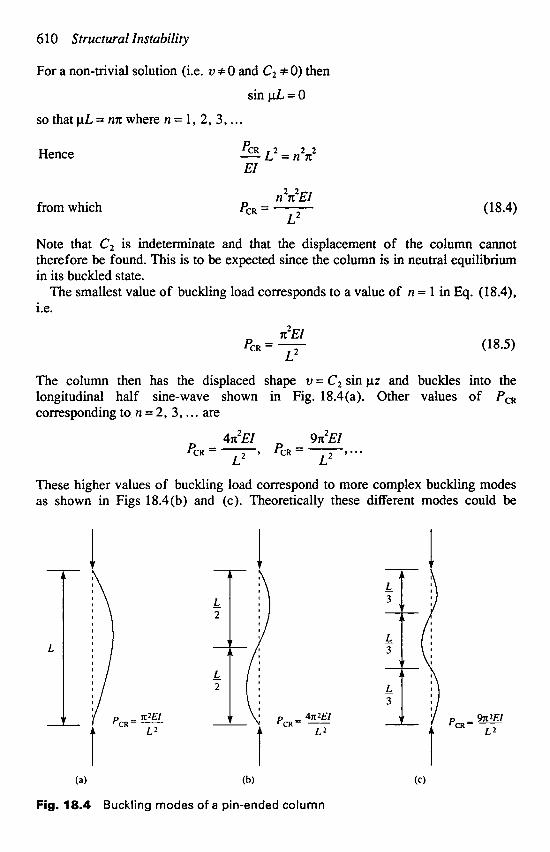
The column then has the displaced shape v = C2 sin pz and buckles into the longitudinal half sine-wave shown in Fig. 18.4(a). Other values of PcR corresponding to n = 2, 3, . . . are
L2
4n2EI 9n2EI P - T’...
L PCR = - 7 C R -
L2
These higher values of buckling load correspond to more complex buckling modes as shown in Figs 18.4(b) and (c). Theoretically these different modes could be
Fig. 18.4 Buckling modes of a pin-ended column

Euler theory f o r slender columns 61 1
produced by applying external restraints to a slender column at the points of contraflexure to prevent lateral movement. However, in practice, the lowest value is never exceeded since high stresses develop at this load and failure of the column ensues. We are not therefore concerned with buckling loads higher than this.
Buckling load for a column with fixed ends In practice, columns usually have their ends restrained against rotation so that they are, in effect, fixed. Figure 18.5 shows a column having its ends fixed and subjected to an axial compressive load that has reached the critical value, PCR, so that the column is in a state of neutral equilibrium. In this case the ends of the column are subjected to fixing moments, M F , in addition to axial load. Thus at any section Z the bending moment, M, is given by
M = PCRV- MF Substituting for M from Eq. (13.3) we have
d2v PCR MF -- - -- V + - (18.6) dz2 EI EI
Rearranging we obtain
d2v PCR MF - + - v = - (18.7) dz2 EI EI
the solution of which is
v = c, cos pz + c2 Sin pz + MF/PcR (1 8.8)
where p2 = PcR/EI
Fig. 18.5 Buckling of a slender column with fixed ends
6 12 Structural Instability
When z = 0, v = 0 so that C, = -MF/PcR. Further v = 0 at z = L, hence
MF cos pL + C2 sin p L + - MF O=-- PCR PCR
which gives MF (1-cospL)
PCR sin pL c ---
2 -
Hence Eq. (1 8.8) becomes
(1 - cos pL) v = 2% [cospz+ s i n p - 11 (18.9)
Note that again v is indeterminate since M, cannot be found. Also since dv/dz = 0 at z = L we have from Eq. (18.9)
PCR sin pL
o = 1 -cos pL whence cos p L = 1 and pL = nn where n = 0,2,4, . . . For a non-trivial solution, i.e. N f 0, and taking the smallest value of buckling load (n = 2) we have
4n2EI P& = - ( 1 8.1 0)
L2
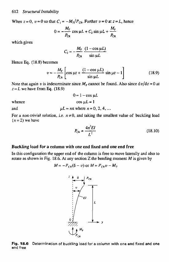
Buckling load for a column with one end fixed and one end free In this configuration the upper end of the column is free to move laterally and also to rotate as shown in Fig. 18.6. At any section Z the bending moment M is given by
M = -Pc,(6 - V ) or M = PCRV - M,
Fig. 18.6 Determination of buckling load for a column with one end fixed and one end free
Euler theory for slender columns 61 3
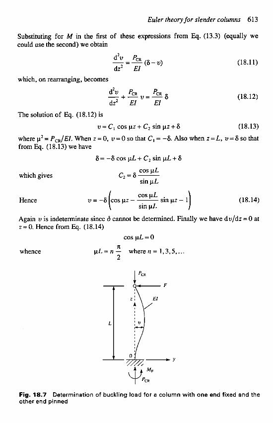
Substituting for M in the first of these expressions from Eq. (13.3) (equally we could use the second) we obtain
d2v PCR -- -- (6 - v) dz2 EI
(18.11)
which, on rearranging, becomes
(18.12) d2v PCR PCR - +-v=-6 dz2 EI EI
The solution of Eq. (18.12) is
v = c , c o s p z + c ~ s i n p z + 6 (1 8.13)
where p2 = PcR/EI. When z = 0, v = 0 so that C, = -6. Also when z = L, v = 6 so that from Eq. (18.13) we have
6 = - 6 c o s p L + C , s i n p L + 6
cos p L which gives C , = S -
sin p L
cos p L ( sin pL v = -6 cospz- - sin pz - 1) (18.14) Hence
Again u is indeterminate since 6 cannot be determined. Finally we have dv/dz = 0 at z = 0. Hence from Eq. (18.14)
cos pL = 0 x
whence p L = n - wheren= 1,3,5, ... 2
Fig. 18.7 Determination of buckling load for a column with one end fixed and the other end pinned

614 Structural Instability
Thus taking the smallest value of buckling load (corresponding to n = 1) we obtain
a2EI PCR = -
4L2 (1 8.15)
Buckling of a column with one end fixed, the other pinned The column in this case is allowed to rotate at one end but requires a lateral force, F, to maintain its position (Fig. 18.7).
At any section Z the bending moment M is given by M = PCRV + F ( L - Z)
Substituting for M from Eq. (13.3) we have
d2v PCR F dz2 EI EI
v - - (L - 2) - = --
which, on rearranging, becomes
d2v PCR F (L - z) - +-v=--
dz2 EI EI The solution of Eq. (18.17) is
v = C, cos pz + C, sin pz - 2 (L - z) PCR
Now dv/dz = 0 at z = 0, thus F
O=pC2+- PCR
F whence C, = --
When z = L , v = 0, hence PPCR
0 = C, cos p L + C, sin pL
which gives
Thus Eq. (18.18) becomes F v = -
PPCR Also v=Oatz=O.Thus
or
F c, = - tan pL PPCR
(18.16)
(1 8.17)
(1 8.18)
[tan p L cos pz - sin pz - p(L - z)] ( 1 8.1 9)
0 =tan p L - pL pL = tan pL (1 8.20)
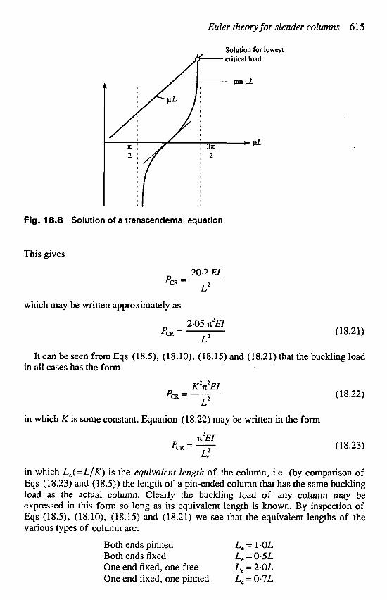
Equation (18.20) is a transcendental equation which may be solved graphically as shown in Fig. 18.8. The smallest non-zero value satisfying Eq. (18.20) is approximately 4-49.
Euler theory for slender columns 615
Fig. 18.8 Solution of a transcendental equation
This gives
20.2 EI PCR = -
L2
which may be written approximately as
2.05 x’EI (18.21)
It can be seen from Eqs (18.5), (18.10), (18.15) and (18.21) that the buckling load
L2 PCR =
in all cases has the form
K’X’EI L2
X’EI
L,‘
PCR = - (18.22)
in which K is some constant. Equation (18.22) may be written in the form
PCR = - (1 8.23)
in which L , ( = L / K ) is the equivalent length of the column, i.e. (by comparison of Eqs (18.23) and (18.5)) the length of a pin-ended column that has the same buckling load as the actual column. Clearly the buckling load of any column may be expressed in this form so long as its equivalent length is known. By inspection of Eqs (18.5), (18.10), (18.15) and (18.21) we see that the equivalent lengths of the various types of column are:
Both ends pinned Both ends fixed One end fixed, one free
Le = 1 *OL
Le = 2.0L Le = 0.5 L
One end fixed, one pinned Le = 0.7L
6 16 Structural Instability
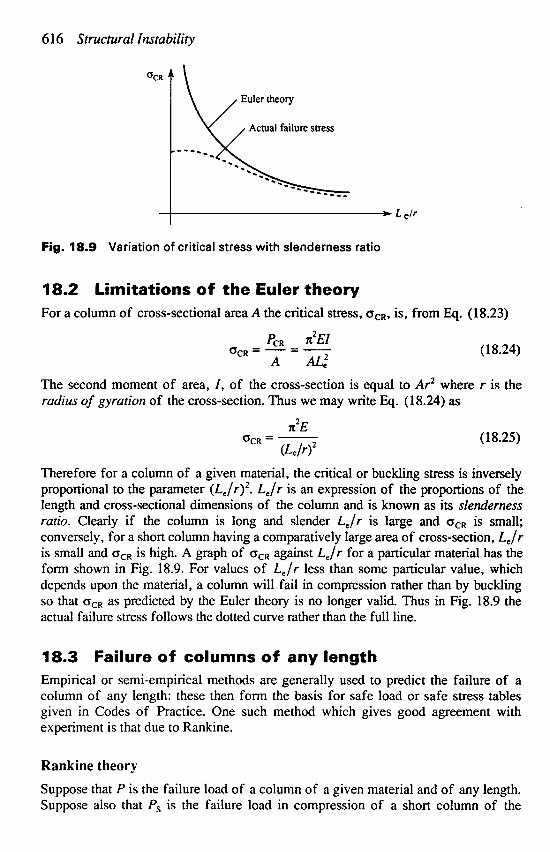
Fig. 18.9 Variation of critical stress with slenderness ratio
18.2 Limitations of the Euler theory For a column of cross-sectional area A the critical stress, bCR, is, from Eq. (18.23)
PCR K ~ E I b C R = - -- - (1 8.24)
A AL.: The second moment of area, I , of the cross-section is equal to Ar2 where r is the radius of gyration of the cross-section. Thus we may write Eq. (18.24) as
K 2 E
(Le/rI2 b C R = - (18.25)
Therefore for a column of a given material, the critical or buckling stress is inversely proportional to the parameter (L,./r)’. L,/r is an expression of the proportions of the length and cross-sectional dimensions of the column and is known as its slenderness ratio. Clearly if the column is long and slender L,/r is large and bCR is small; conversely, for a short column having a comparatively large area of cross-section, Le/r is small and oCR is high. A graph of oCR against L,/r for a particular material has the form shown in Fig. 18.9. For values of Le/r less than some particular value, which depends upon the material, a column will fail in compression rather than by buckling so that ocR as predicted by the Euler theory is no longer valid. Thus in Fig. 18.9 the actual failure stress follows the dotted curve rather than the full line.
18.3 Failure of columns of any length Empirical or semi-empirical methods are generally used to predict the failure of a column of any length: these then form the basis for safe load or safe stress tables given in Codes of Practice. One such method which gives good agreement with experiment is that due to Rankine.
Rankine theory
Suppose that P is the failure load of a column of a given material and of any length. Suppose also that P, is the failure load in compression of a short column of the
Failure of columns of any length 617
same material and that PcR is the buckling load of a long slender column, again of the same material. The Rankine theory proposes that
1 1 1 _ - - -+- p PS PCR
(1 8.26)
Equation (18.26) is valid for a very short column since l/P,-R + 0 and P then + P,; the equation is also valid for a long slender column since 1/P, is small compared with l/PcR; thus P+ PcR. Equation (18.26) is therefore seen to hold for extremes in column length.
Now let cs be the yield stress in compression of the material of the column and A its cross-sectional area. Then
P, = CTSA
Also from Eq. (18.23)
X ~ E I PCR = -
L: Substituting for P, and PcR in Eq. (18.26) we have
1 +- 1 1 P a s A x2EIfL2 -=-
Thus
so that
1 X ~ E I / L ~ + G,A
P G,AX~EI/L: -- -
O,AX~EI f ~ f X’EI/L: + O,A
P =
Dividing top and bottom of the right-hand side of this equation by x2EI/L: we have
%A QALS X ~ E I
P = 1+-
But I = Ar2 so that
%A 2
P = I++($) X’E
which may be written
%A P = 1 + k(L,/r)’
(18.27)
in which k is a constant that depends upon the material of the column. The failure
618 Structural Instability
stress in compression, oc, of a column of any length is then, from Eq. (18.27)
P OS oc=-= A 1 +k(Le/r)2
(18.28)
Note that for a column of a given material oc is a function of the slenderness ratio, Le/.-
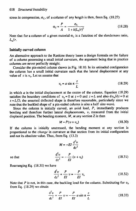
Initially curved column
An alternative approach to the Rankine theory bases a design formula on the failure of a column possessing a small initial curvature, the argument being that in practice columns are never perfectly straight.
Consider the pin-ended column shown in Fig. 18.10. In its unloaded configuration the column has a small initial curvature such that the lateral displacement at any value of z is v,. Let us assume that
v, = c2 sin x - L
(18.29)
in which a is the initial displacement at the centre of the column. Equation (1 8.29) satisfies the boundary conditions of v, = 0 at z = 0 and z = L and also dv,/dz = 0 at z = L/2; the assumed deflected shape is therefore reasonable, particularly since we note that the buckled shape of a pin-ended column is also a half sine-wave.
Since the column is initially curved, an axial load, P, immediately produces bending and therefore further lateral displacements, v, measured from the initial displaced position. The bending moment, M, at any section Z is then
M = P(v + v,) (18.30)
If the column is initially unstressed, the bending moment at any section is proportional to the change in curvature at that section from its initial configuration and not its absolute value. Thus, from Eq. (13.3)
d2v M = - E I -
dz2
so that
Rearranging Eq. (18.31) we have
d2v P P vo - + - v = --
dz2 EI EI
(18.3 1)
(18.32)
Note that P is not, in this case, the buckling load for the column. Substituting for vo from EQ. (1 8.29) we obtain
d2v P P 2
dz’ EI EI L a sin x - - + - v = -- (18.33)
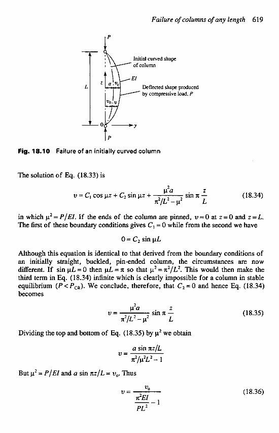
Failure of columns of any length 619
Fig. 18.10 Failure of an initially curved column
The solution of Eq. (18.33) is
z sin x - (18.34)
in which p2 = P/EI. If the ends of the column are pinned, v = 0 at z = 0 and z = L. The first of these boundary conditions gives C1 = 0 while from the second we have
C12a v = CI cos pz + C2 sin p z + x2/L2 - p2 L
O = C2 sin pL
Although this equation is identical to that derived from the boundary conditions of an initially straight, buckled, pin-ended column, the circumstances are now different. If sin pL.= 0 then p L = x so that p2 = n2/L2. This would then make the third term in Eq. (18.34) infinite which is clearly impossible for a column in stable equilibrium ( P < PcR). We conclude, therefore, that C2 = 0 and hence Eq. (18.34) becomes
Z S i n X - (1 8.35) p2a
V = x2/L2 - p2 L
Dividing the top and bottom of Eq. (18.35) by p2 we obtain
a sin RZ fL V =
n2/p2L2 - 1 But p2 = P/EI and a sin x z / L = vo. Thus
(18.36) VO V = ~ ' E I 1 PL2 --

620 Structural Instability
From Eq. (18.5) we see that n2EI/L2 = P,,, the buckling load for a perfectly straight pin-ended column. Hence Eq. ( 1 8.36) becomes
(1 8.37)
It can be seen from Eq. (18.37) that the effect of the compressive load, P , is to increase the initial deflection, uo, by a factor l / (PCR/P - 1). Clearly as P approaches PcR, u tends to infinity. In practice this is impossible since material breakdown would occur before P,, is reached.
If we consider displacements at the mid-height of the column we have, from Eq. (18.37),
a v, = -
P PCR --
Rearranging we obtain
Equation (18.38) represents a linear relationship between u, and u, /P . Thus in an actual test on an initially curved column a graph of v, against u,/P will be a straight line as the critical condition is approached. The gradient of the line is Pc, and its intercept on the u, axis is equal to a, the initial displacement at the mid-height of the column. The graph (Fig. 18.1 1) is known as a Southwell plot and gives a convenient, nondestructive, method of determining the buckling load of columns.
The maximum bending moment in the column of Fig. 18.10 occurs at mid-height and is
M,, = P ( a + u,)
Substituting for v, from Eq. (18.38) we have
or M m x = P a - ( PC? P ) (18.39)
The maximum compressive stress in the column occurs in an extreme fibre and is, from Eq. (9.15)
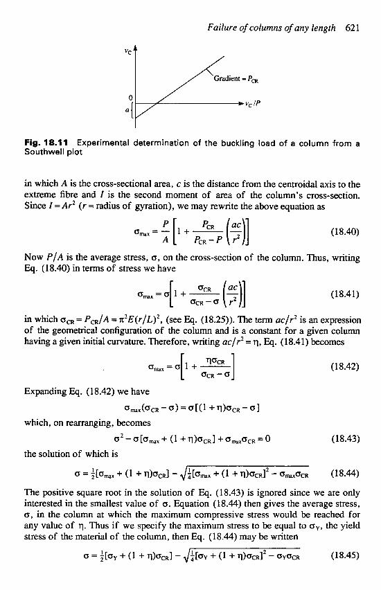
Failure of columns of any length 62 1
Fig. 18.11 Southwell plot
Experimental determination of the buckling load of a column from a
in which A is the cross-sectional area, c is the distance from the centroidal axis to the extreme fibre and I is the second moment of area of the column’s cross-section. Since I = Ar2 ( r = radius of gyration), we may rewrite the above equation as
am, = P [ 1 + PCR (E)] (18.40)
Now PIA is the average stress, a, on the cross-section of the column. Thus, writing Eq. (18.40) in terms of stress we have
A PCR- P r2
o, ,=a l+- - (18.41)
in which bCR = PcR/A = x2E(r /L)2 , (see Eq. (18.25)). The term ac/r2 is an expression of the geometrical configuration of the column and is a constant for a given column having a given initial curvature. Therefore, writing ac/r2 = q, Eq. (18.41) becomes
[ 2:a (31
[ ::a] amx=a 1+- (1 8.42)
Expanding Eq. (18.42) we have
amx(aCR - a) = a [(l + q b C R - 0 1 which, on rearranging, becomes
a 2 - ~ [ ~ m a x + ( l + q ) a C R l + a m a x a C R = O ( 18.43) the solution of which is
I 1 0 = z[amx + (1 + q ) a C R ] - Ja[%ix + (1 + q ) a C R I 2 - % a x o C R (18.44)
The positive square root in the solution of Eq. (18.43) is ignored since we are only interested in the smallest value of a. Equation (18.44) then gives the average stress, a, in the column at which the maximum compressive stress would be reached for any value of q. Thus if we specify the maximum stress to be equal to cry, the yield stress of the material of the column, then Eq. (1 8.44) may be written
0 = i[.Y + (1 + q)ocRl - J a [ a Y 1 + (1 + q ) a C R I 2 - OYoCR ( 18.45)
622 Structural Instability
It has been found from tests on mild steel pin-ended columns that failure of an initially curved column occurs when the maximum stress in an extreme fibre reaches the yield stress, ay. Also, from a wide range of tests on mild steel columns, Robertson concluded that
q = 0403( t) Substituting this value of q in Eq. (18.45) we obtain
0 = +[by + (1 + o . o 0 3 t > a C R ] - di[ay + (1 + 0 ' ~ 3 ~ ) ~ C R ] * - GyacR (18.46)
In Eq. (18.46) cy is a material property while aCR (from Eq. (18.25)) depends upon ,
Young's modulus, E, and the slenderness ratio of the column. Thus Eq. (18.46) may be used to determine safe axial loads or stresses (a) for columns of a given material in terms of the slenderness ratio. Codes of Practice tabulate maximum allowable values of average compressive stress against a range of slenderness ratios.
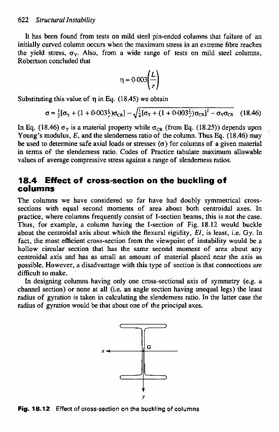
18.4 Effect of cross-section on the buckling of columns The columns we have considered so far have had doubly symmetrical cross- sections with equal second moments of area about both centroidal axes. In practice, where columns frequently consist of I-section beams, this is not the case. Thus, for example, a column having the I-section of Fig. 18.12 would buckle about the centroidal axis about which the flexural rigidity, EI, is least, i.e. Gy. In fact, the most efficient cross-section from the viewpoint of instability would be a hollow circular section that has the same second moment of area about any centroidal axis and has as small an amount of material placed near the axis as possible. However, a disadvantage with this type of section is that connections are difficult to make. '
In designing columns having only one cross-sectional axis of symmetry (e.g. a channel section) or none at all (i.e. an angle section having unequal legs) the least radius of gyration is taken in calculating the slenderness ratio. In the latter case the radius of gyration would be that about one of the principal axes.
Fig. 18.12 Effect of cross-section on the buckling of columns
Stability of beams under transverse and axial loads 623
Another significant factor in determining the buckling load of a column is the method of end support. We saw in Section 18.1 that considerable changes in buckling load result from changes in end conditions. Thus a column with fixed ends has a higher value of buckling load than if the ends are pinned (cf. Eqs (18.5) and (18.10)). However, we have seen that by introducing the concept of equivalent length, the buckling loads of all columns may be referred to that of a pin-ended column no matter what the end conditions. It follows that Eq. (18.46) may be used for all types of end condition, provided that the equivalent length, Le, of the column is used. Codes of Practice list equivalent or ‘effective’ lengths of columns for a wide variety of end conditions. Furthermore, although a column buckles naturally in a direction perpendicular to the axis about which EI is least, it is possible that the column may be restrained by external means in this direction so that buckling can only take place about the other axis.
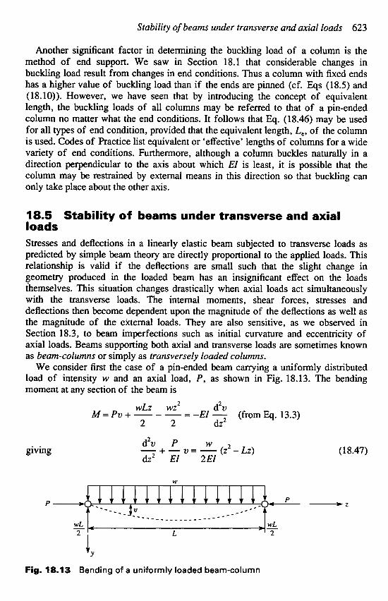
18.5 Stability of beams under transverse and axial loads Stresses and deflections in a linearly elastic beam subjected to transverse loads as predicted by simple beam theory are directly proportional to the applied loads. This relationship is valid if the deflections are small such that the slight change in geometry produced in the loaded beam has an insignificant effect on the loads themselves. This situation changes drastically when axial loads act simultaneously with the transverse loads. The internal moments, shear forces, stresses and deflections then become dependent upon the magnitude of the deflections as well as the magnitude of the external loads. They are also sensitive, as we observed in Section 18.3, to beam imperfections such as initial curvature and eccentricity of axial loads. Beams supporting both axial and transverse loads are sometimes known as beam-columns or simply as transversely loaded columns.
We consider first the case of a pin-ended beam carrying a uniformly distributed load of intensity w and an axial load, P, as shown in Fig. 18.13. The bending moment at any section of the beam is
d2v WLZ wz M = pv + - - - - - -EI - 2 2 dz 2
2
(from Eq. 13.3)
d2v P W giving - +-v=- (z2 - Lz) (18.47)
dz2 EI 2EI
Fig. 18.13 Bending of a uniformly loaded beam-column

624 Structural Instability
The standard solution of Eq. (1 8.47) is
v = C, cos pz + C, sin pz + - w ( z 2 - L z - ; ) 2P
where C, and C2 are unknown constants and pz = P/EZ. Substituting the boundary conditions v = 0 at z = 0 and L gives
W W c, = - , c2= (1 - cos pt) p2P p 2 p sin p~
so that the deflection is determinate for any value of w and P and is given by
1 - cos p L v = w [cos p z + ( sin p L )sin pz ] + $ (z2 - Lz - ;) (1 8.48)
In beamcolumns, as in beams, we are primarily interested in maximum values of stress and deflection. For this particular case the maximum deflection occurs at the centre of the beam and is, after some transformation of Eq. (18.48)
P2P
WLZ (1 8.49) v , x = - ( s e c T - l ) - - W PL
P2P 8P
The corresponding maximum bending moment is
WLZ M,, = -Pv,, - -
8
or, from Eq. (1 8.49) M , , = ~ ( l - s e c $ ) (18.50)
We may rewrite Eq; (18.50) in terms of the Euler buckling load, P,, = nZEI/L2, for a pin-ended column. Hence
M,, = - wL2 - PCR ( 1 - sec - 4 E) P2
(18.51) n2 P
Fig. 18.14 Beam-column supporting a point load

Stability of beams under transverse and axial loads 625
As P approaches PCR the bending moment (and deflection) becomes infinite. However, the above theory is based on the assumption of small deflections (otherwise d2v/dz2 would not be a close approximation for curvature) so that such a deduction is invalid. The indication is, though, that large deflections will be produced by the presence of a compressive axial load no matter how small the transverse load might be.
Let us consider now the beam-column of Fig. 18.14 with pinned ends carrying a concentrated load W at a distance a from the right-hand support.
Forz s L - a ,
andforz 3 L - a ,
Writing
Equation (1 8.52) becomes
d2v W EI - = - M = -pv - -
dz2 L (L -a )& - z)
p2 = PIE1
d2v Wa - + p v = - - Z dz2 EIL
the general solution of which is
Wa
PL v = C , cos pz + C, sin pz - - Z
Similarly the general solution of Eq. (18.53) is
W
PL v = C, cos pz + C, sin pz - - (L - a)(L - z )
(18.52)
(18.53)
(18.54)
(1 8.55)
where C,, C?, C3 and C, are constants which are found from the boundary conditions as follows.
When z = 0, v = 0, therefore from Eq. (18.54) C , = 0. At z = L, u = 0 giving, from Eq. (18.55), C, = -C, tan pL. At the point of application of the load the deflection and slope of the beam given by Eqs (18.54) and (18.55) must be the same. Hence, equating deflections,
wu Wa
PL PL C, sin p(L - a) - - (L - a) = C, [sin p(L - a) - tan pL cos p(L - a)] - - (L - a)
and equating slopes
w u W PL PL
C2p cos p(L - a) - - = C,p[cos p(L - a) + tan p!. sin p(L - a)] + - (L - a)

626 Structural Instability
Solving the above equations for C2 and C4 and substituting for C,, Cz, C3 and C4 in Eqs (1 8.54) and (1 8.55) we have
w sin p a wa P p sin p L PL
V = sinpz- - z for z s L - a (1 8.56)
w sin p ( L - a ) W V = sin p(L - z) - - (L - a)(L - z) for z P L - a (18.57)
P p sin p L PL
These equations for the beam-column deflection enable the bending moment and resulting bending stresses to be found at all sections.
A particular case arises when the load is applied at the centre of the span. The deflection curve is then symmetrical with a maximum deflection under the load of
w p L WL urn, = - tan---
2Pp 2 4P
Finally we consider a beamcolumn subjected to end moments, MA and M,, in addition to an axial load, P (Fig. 18.15). The deflected form of the beam-column may be found by using the principle of superposition and the results of the previous case. First we imagine that M, acts alone with the axial load, P . If we assume that the point load, W , moves towards B and simultaneously increases so that the product W a = constant = M, then, in the limit as a tends to zero, we have the moment M, applied at B. The deflection curve is then obtained from Eq. (18.56) by substituting pa for sin p a (since pa is now very small) and M, for Wa. Thus
(18.58)
We find the deflection curve corresponding to MA acting alone in a similar way. Suppose that W moves towards A such that the product W ( L - a ) = constant = MA. Then as ( L - a ) tends to zero we have sin p ( L - a) = p ( L - a) and Eq. (18.57) becomes
-“I L v=-[ MA sin p ( L - Z )
P sinpL (18.59)
The effect of the two moments acting simultaneously is obtained by superposition of the results of Eqs (18.58) and (18.59). Hence, for the beam-column of Fig. 18.15
(1 8.60) -“I L
Equation (18.60) is also the deflected form of a beam-column supporting eccen- trically applied end loads at A and B. For example, if e A and e , are the eccentricities of P at the ends A and B, respectively, then MA = Pe,, M, = Pe,, giving a deflected form of
sin p(L - z ) (L - z)] u = e , --- (18.61)
(s in sin p pZ L : ) + e , [ sin p L L
Energy method for the calculation of buckling loads in columns 627
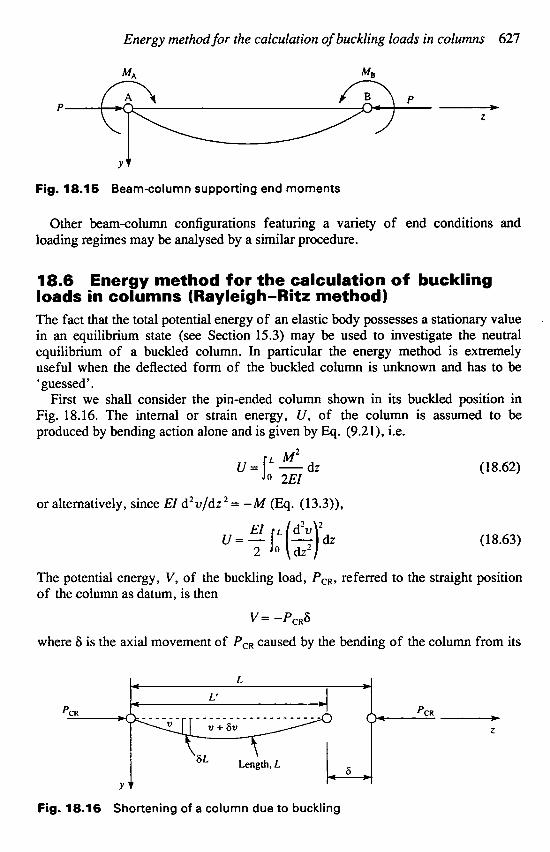
Fig. 18.15 Beam-column supporting end moments
Other beamcolumn configurations featuring a variety of end conditions and loading regimes may be analysed by a similar procedure.
18.6 Energy method for the calculation of buckling loads in columns (Rayleigh-Ritz method) The fact that the total potential energy of an elastic body possesses a stationary value in an equilibrium state (see Section 15.3) may be used to investigate the neutral equilibrium of a buckled column. In particular the energy method is extremely useful when the deflected form of the buckled column is unknown and has to be ‘guessed’.
First we shall consider the pin-ended column shown in its buckled position in Fig. 18.16. The internal or strain energy, U, of the column is assumed to be produced by bending action alone and is given by Eq. (9.21), i.e.
(18.62) L M 2 o 2Et
i J=I -dz or alternatively, since Et d2u/dz2 = -M (Eq. (13.3)),
Et L d2v 2 u=- (18.63)
The potential energy, V, of the buckling load, P,,, referred to the straight position of the column as datum, is then
2 l O ( i +
v = -P,,6
where 6 is the axial movement of PCR caused by the bending of the column from its
Fig. 18.16 Shortening of a column due to buckling
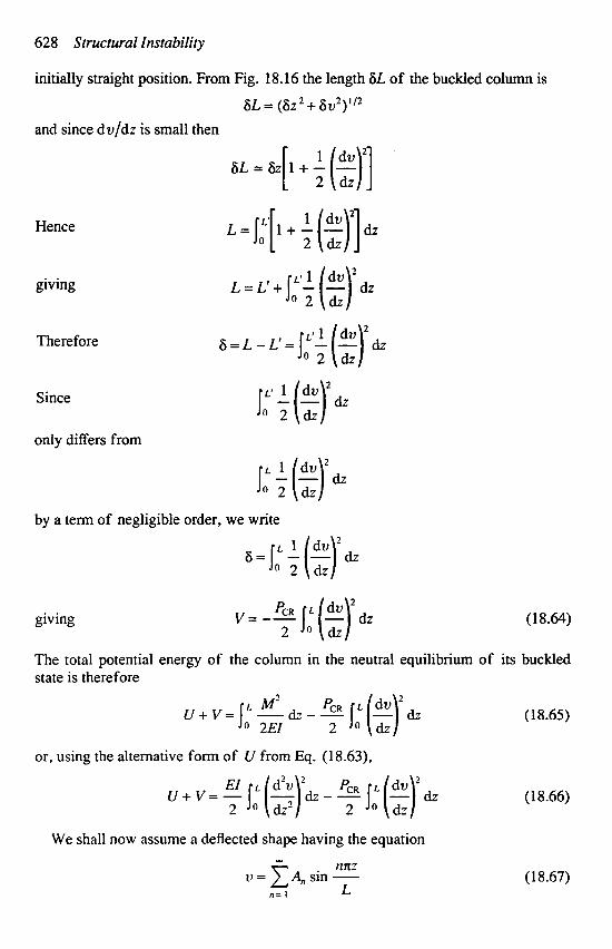
628 Structural Instability
initially straight position. From Fig. 18.16 the length 6L of the buckled column is
6L = (622 + 6v2)"2 and since dv/dz is small then
Hence
giving
Therefore
Since
only differs from
I" L (e)' & 2 dz
by a term of negligible order, we write
giving (1 8.64)
The total potential energy of the column in the neutral equilibrium of its buckled state is therefore
u+v= L M' --dz---J0(-) PCR L dv ' dz In 2EI 2
or, using the alternative form of U from Eq. (18.63),
We shall now assume a deflected shape having the equation w
Ilnz 11 = 1 A, sin -
n = 1 L
(1 8.65)
(18.66)
(1 8.67)
Energy method f o r the calculation of buckling loads in columns 629
This satisfies the boundary conditions of
and is capable, within the limits for which it is valid and if suitable values for the constant coefficients, A , , are chosen, of representing any continuous curve. We are therefore in a position to find P,, exactly. Substituting Eq. (18.67) into Eq. (18.66) gives
U + V = I (?r[? n2A, sin - nm )’.. - 3 I,” ($[: cos E)’.. (1 8.68) 2 O L L 2 L
The product terms in both integrals of Eq. (18.68) disappear on integration leaving only integrated values of the squared terms. Thus
(18.69)
Assigning a stationary value to the total potential energy of Eq. (18.69) with respect to each coefficient, A,, in turn, then taking A , as being typical, we have
a(U + v) 7t4EIn4A, 7t2PcRn2An = O - - -
aA, 2 ~ 3 2 L
from which
as before. We see that each term in Eq. (1 8.67) represents a particular deflected shape with a
corresponding critical load. Hence the first term represents the deflection of the column shown in Fig. 18.16 with P C R = x Z E I / L Z . The second and third terms correspond to the shapes shown in Fig. 18.4(b) and (c) having critical loads of 45c’EI/L’ and 9n2EI/L2 and so on. Clearly the column must be constrained to buckle into these more complex forms. In other words, the column is being forced into an unnatural shape, is consequently stiffer and offers greater resistance to buckling, as we observe from the higher values of critical load.
If the deflected shape of the column is known, it is immaterial which of Eqs (18.65) or (18.66) is used for the total potential energy. However, when only an approximate solution is possible, Eq. (18.65) is preferable since the integral involving bending moment depends upon the accuracy of the assumed form of v, whereas the corresponding term in Eq. (18.66) depends upone the accuracy of d2v/dz’. Generally, for an assumed deflection curve v is obtained much more accurately than d’v/dz ’.
Suppose that the deflection curve of a particular column is unknown or extremely complicated. We then assume a reasonable shape which satisfies as far as possible the end conditions of the column and the pattern of the deflected shape (Rayleigh-Ritz method). Generally the assumed shape is in the form of a finite
630 Structural Instability
series involving a series of unknown constants and assumed functions of z. Let us suppose that v is given by
v = A,fI(Z) + A f 2 ( z ) + A f & ) Substitution in Eq. (18.65) results in an expression for total potential energy in terms of the critical load and the coefficients A , , At and A , as the unknowns. Assigning stationary values to the total potential energy with respect to A , , A2 and A, in turn produces three simultaneous equations from which the ratios A , / A 2 , A , / A , and the critical load are determined. Absolute values of the coefficients are unobtainable since the displacements of the column in its buckled state of neutral equilibrium are indeterminate.
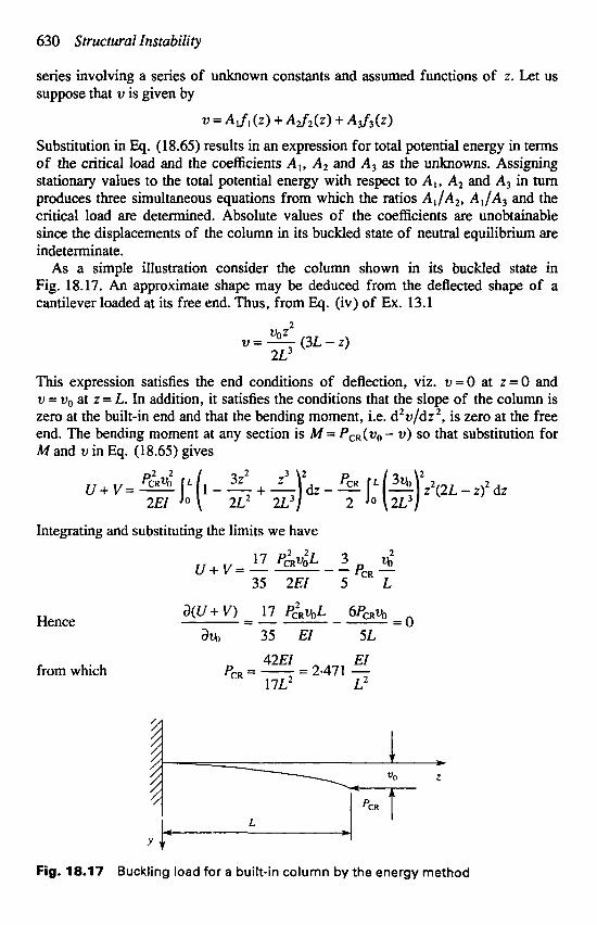
As a simple illustration consider the column shown in its buckled state in Fig. 18.17. An approximate shape may be deduced from the deflected shape of a cantilever loaded at its free end. Thus, from Eq. (iv) of Ex. 13.1
2
v=- (3L - z ) VOZ
2 ~ 3
This expression satisfies the end conditions of deflection, viz. v = O at z=O and v = v,, at z = L. In addition, it satisfies the conditions that the slope of the column is zero at the built-in end and that the bending moment, Le. d2v/dz2, is zero at the free end. The bending moment at any section is M = PC,(vO- v) so that substitution for M and v in Eq. ( 1 8.65) gives
2 5 1,' (3) z2(2L - z)2 dz u+ v = - I,' ( l - - + Lp - p&4 3Z2
2EI 2 ~ 2 2 ~ 3 2
Integrating and substituting the limits we have
17 PGRv;L 3 4 35 2EI 5 L
PCR - u + v = - ---
a(u+v) 17 P;R~,$ 6P&V, =----- Hence - 0 a% 35 EI 5L 42EI EI
from which PCR = - = 2.471 - 17L' L2
Fig. 18.17 Buckling load for a built-in column by the energy method

Problems 631
This value of critical load compares with the exact value (see Eq. (18.15)) of rc2EI/4L2=2-467EZ/L2; the error, in this case, is seen to be extremely small. Approximate values of critical load obtained by the energy method are always greater than the correct values. The explanation lies in the fact that an assumed deflected shape implies the application of constraints in order to force the column to take up an artificial shape. This, as we have seen, has the effect of stiffening the column with a consequent increase in critical load.
It will be observed that the solution for the above example may be obtained by simply equating the increase in internal energy ( V ) to the work done by the external critical load (-V). This is always the case when the assumed deflected shape contains a single unknown coefficient such as vo in the above example.
In this chapter we have investigated structural instability with reference to the overall buckling or failure of columns subjected to axial load and also to bending. The reader should also be aware that other forms of instability occur. Thus the compression flange in an I-section plate girder can buckle laterally when the girder is subjected to bending moments unless it is restrained. Furthermore, thin-walled open section beams that are weak in torsion can exhibit torsional instability when subjected to axial load. These forms of instability are considered in more advanced texts.
Problems P.18.1 A uniform column of length L and flexural rigidity EI is built-in at one
end and is free at the other. It is designed so that its lowest buckling load is P. (Fig. P.18.1 (a)). Subsequently it is required to carry an increased load and for that it is provided with a lateral spring at the free end (Fig. P.18.1(b)). Determine the necessary spring stiffness, k, so that the buckling load is 4P.
k = 4Pp/(jd - tan p L ) where p2 = P/EI. Ans.
Fig. P.18.1
P.18.2 A pin-ended column of length L and flexural rigidity EI is reinforced to give a flexural rigidity 4EI over its central half. Determine its lowest buckling load.
Ans. 24.2EI/L2.
632 Structural Instability
P.18.3 A uniform pin-ended column of length L and flexural rigidity EI has an initial curvature such that the lateral displacement at any point between the column and the straight line joining its ends is given by
4z u, = a - (L - z )
L2 where a is the initial displacement at the mid-length of the column and the origin for z is at one end.
Show that the maximum bending moment due to a compressive axial load, P , is given by
M,, = - 8aP (sec PL - 1) where p 2 p = - w2 EI
P.18.4 A compression member is made of circular-section tube having a diameter d and thickness t and is curved initially so that its initial deflected shape may be represented by the expression
v, = 6 sin(:)
in which 6 is the displacement at its mid-length and the origin for z is at one end.
direct stress, o,,,, given by Show that if the ends are pinned, a compressive load, P , induces a maximum
P 1 46 x dt l-a d
where a = P/P , , and P,, = d E Z / L * . Assume that t is small compared with d so that the cross-sectional area of the tube is xdt and its second moment of area is xd3t/8.
In the experimental determination of the buckling loads for 12-5 mm diameter, mild steel, pin-ended columns, two of the values obtained were:
P.18.5
(i) (ii) (a) Determine whether either of these values conforms to the Euler theory for
(b) Assuming that both values are in agreement with the Rankine formula, find
Am. (a) (i) conforms with Euler theory.
P.18.6 A tubular column has an effective length of 2.5 m and is to be designed to cany a safe load of 300 kN. Assuming an approximate ratio of thickness to external diameter of 1/16, determine a practical diameter and thickness using the Rankine formula with os = 330 N/mm’ and k = 1/7500. Use a safety factor of 3.
length 500 mm, load 9800 N, length 200 mm, load 26 400 N.
buckling load.
the constants os and k. Take E = 200 OOO N/mm’.
(b) os = 317 N/mm’, k = 1.16 x
Ans. Diameter = 128 mm, thickness = 8 mm.
Problems 633
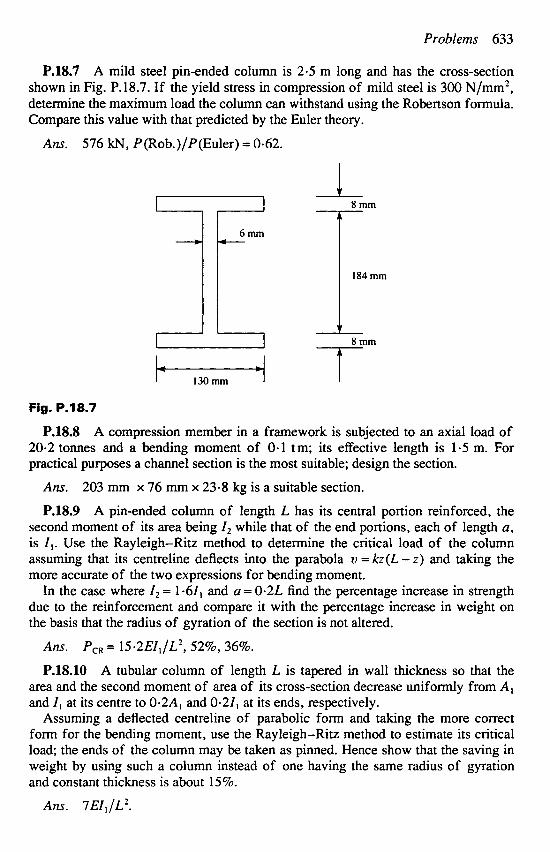
P.18.7 A mild steel pinended column is 2.5 m long and has the cross-section shown in Fig. P.18.7. If the yield stress in compression of mild steel is 300 N/mm2, determine the maximum load the column can withstand using the Robertson formula. Compare this value with that predicted by the Euler theory.
Ans. 576 kN, P(Rob.)/P(Euler) = 0.62.
Fig. P.18.7
P.18.8 A compression member in a framework is subjected to an axial load of 20.2 tonnes and a bending moment of 0-1 tm; its effective length is 1.5 m. For practical purposes a channel section is the most suitable; design the section.
Ans.
P.18.9 A pin-ended column of length L has its central portion reinforced, the second moment of its area being I, while that of the end portions, each of length a, is I,. Use the Rayleigh-Ritz method to determine the critical load of the column assuming that its centreline deflects into the parabola u = kz(L - z) and taking the more accurate of the two expressions for bending moment.
In the case where I, = 1-61, and u = 0.2L find the percentage increase in strength due to the reinforcement and compare it with the percentage increase in weight on the basis that the radius of gyration of the section is not altered.
203 mm x 76 mm x 23.8 kg is a suitable section.
Ans.
P.18.10 A tubular column of length L is tapered in wall thickness so that the area and the second moment of area of its cross-section decrease uniformly from A , and I, at its centre to 0.2A, and 0.21, at its ends, respectively.
Assuming a deflected centreline of parabolic form and taking the more correct form for the bending moment, use the Rayleigh-Ritz method to estimate its critical load; the ends of the column may be taken as pinned. Hence show that the saving in weight by using such a column instead of one having the same radius of gyration and constant thickness is about 15%.
P,, = 15.2EI, f L 2 , 5296, 36%.
Ans. 7EI,/Lz.