Chapter 9: Universal Synchronous Asynchronous Receiver Transceiver The PIC18 Microcontroller
The PIC18 Microcontroller
Chapter 9: Universal Synchronous Asynchronous Receiver Transceiver
The PIC18 Microcontroller
Han-Way Huang
Minnesota State University MankatoMinnesota State University, Mankato
H. Huang Transparency No.9-1Copyright @ 2005 Thomson Delmar Learning
The PIC18 Microcontroller
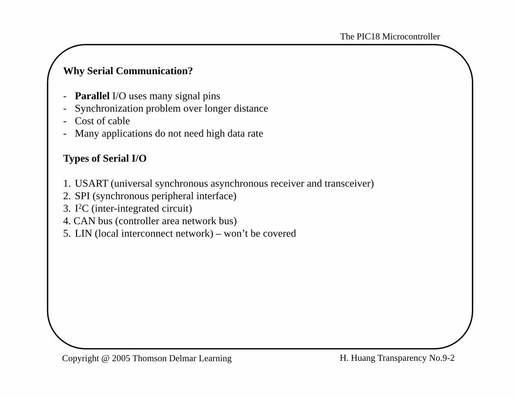
Why Serial Communication?Why Serial Communication?
- Parallel I/O uses many signal pins- Synchronization problem over longer distance- Cost of cableCost of cable- Many applications do not need high data rate
Types of Serial I/O
1. USART (universal synchronous asynchronous receiver and transceiver)2. SPI (synchronous peripheral interface)3. I2C (inter-integrated circuit)4. CAN bus (controller area network bus). C N bus (co t o e a ea etwo bus)5. LIN (local interconnect network) – won’t be covered
H. Huang Transparency No.9-2Copyright @ 2005 Thomson Delmar Learning
The PIC18 Microcontroller
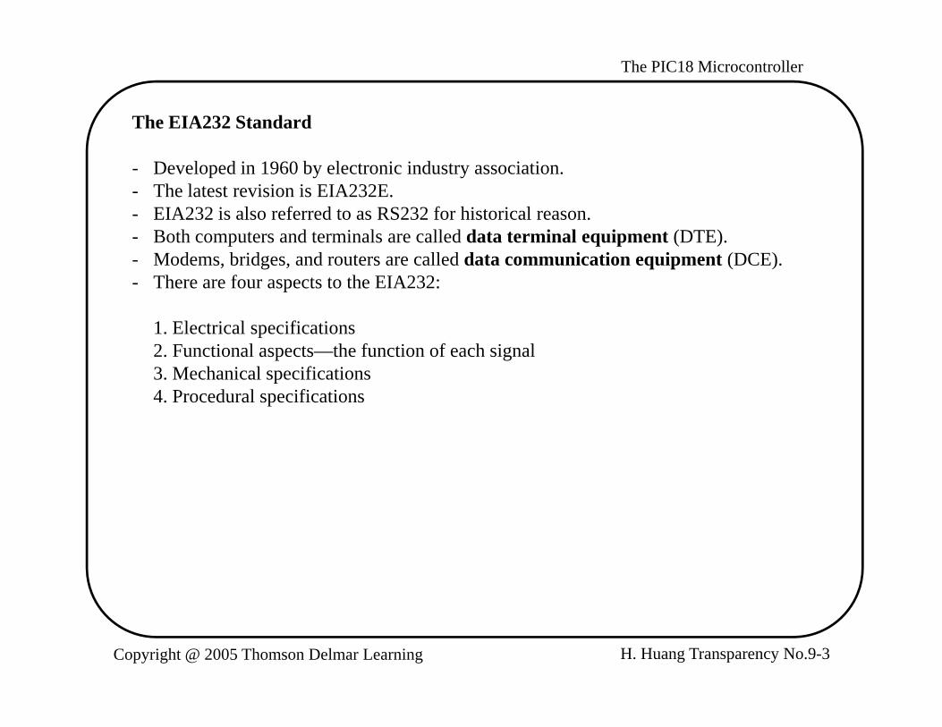
The EIA232 Standard
- Developed in 1960 by electronic industry association.- The latest revision is EIA232E.- EIA232 is also referred to as RS232 for historical reason.- Both computers and terminals are called data terminal equipment (DTE).- Modems, bridges, and routers are called data communication equipment (DCE).- There are four aspects to the EIA232:
1. Electrical specifications2. Functional aspects—the function of each signal3. Mechanical specifications4. Procedural specifications
H. Huang Transparency No.9-3Copyright @ 2005 Thomson Delmar Learning

The PIC18 Microcontroller
Electrical Specifications
- Data rates: EIA232 is applicable to data rate no more than 20 Kbps. The most commonly used data rates are 300, 1200, 2400, 9600, and 19200 baud.
Si l l i- Signal state voltage assignments:1. voltages between -3 V to -25 V are considered as logic 12. voltages between +3 V to 25 V are considered as logic 0
- Signal transfer distance: Signal should be able to transferred correctly up to 15 meters.
H. Huang Transparency No.9-4Copyright @ 2005 Thomson Delmar Learning

The PIC18 Microcontroller
Functional Specifications
- Twenty-two signals are defined.- Signals are divided into six groups:
1. Signal ground and shield2. Primary communication channel3. Secondary communication channel4. Modem status and control signals5. Transmitter and receiver timing signals6. Channel test signals
- Secondary communication channel consists of the same signals as in the primary channel but rarely used.
- Timing signals are not used in asynchronous mode.- Channel test signals are not used in normal communications.
H. Huang Transparency No.9-5Copyright @ 2005 Thomson Delmar Learning

The PIC18 Microcontroller
Primary Communication Channel SignalsPrimary Communication Channel Signals
- Pin 2: transmit data- Pin 3: receive data- Pin 4: request to send signal (RTS)—asserted when in logic 0Pin 4: request to send signal (RTS) asserted when in logic 0- Pin 5: clear to send signal (CTS)—asserted when in logic 0
Modem Status and Control Signals
- Pin 6: data set ready (DSR)—asserted when in logic 0- Pin 20: DTE ready (DTR)—asserted when in logic 0- Pin 8: received line signal detector (CD)—also called carrier detect, asserted in logic 0- Pin 22: ring indicator (RI)—asserted when in logic 0Pin 22: ring indicator (RI) asserted when in logic 0- Pin 23: data signal rate selector—asserted when in logic 0
H. Huang Transparency No.9-6Copyright @ 2005 Thomson Delmar Learning

The PIC18 Microcontroller
Mechanical Specification- Specifies a 25-pin connector- A 9-pin connector is used most often in PC but not specified in the standard
H. Huang Transparency No.9-7Copyright @ 2005 Thomson Delmar Learning

The PIC18 Microcontroller
Signal NameSignal Name SignalDirection
SignalDirection
Protective groundTransmitted dataReceived dataRequest to sendClear to send
Secondary transmitted dataTransmit clock
Secondary received dataReceiver clock
U i d
Bothto DCEto DTEto DCEto DTE
to DCEto DTEto DTEto DTE
12345
1415161718
Data set readySignal groundCarrier detectReservedReserved
UnassignedSecondary request to send
Data terminal readySignal quality detect
Ring indicatorData rate select
to DTEto DTEBoth
to DTE
Both
to DCEto DCEto DTEto DTE
6789
10
181920212223
i dSecondary carrier detectSecondary clear to send
Transmit clockUnassigned to DTE
to DTE
to DCE
Figure 9.1a EIA232E DB25 connector and pin assignment
111213
232425
Unassigned
g p g
Ground5
49
DTE ReadyRing Indicator
4
3
2
1
8
7
6
DTE Ready
Transmitted Data
Received Data
Received Line Signal DetectDCE Ready
Request to send
Clear to Send
H. Huang Transparency No.9-8Copyright @ 2005 Thomson Delmar Learning
Figure 9.1b EIA232E DB9 connector and signal assignment

The PIC18 Microcontroller
EIA232 Procedural Specificationp
Case 1: Point-to-point asynchronous connection
Computer Modem ComputerModem
TxRx
CDCTS
TxRxCDCTS
Computer(DTE) (DCE)
TxRx
CDCTS
TxRxCDCTS
Direct link
p(DTE)(DCE)
CTS
DSRGND
RTSCTS
DSRGND
RTSDSR
GND
RTSCTS
DSRGND
RTS
Tx: transmit data CTS: clear to sendRx: receive data RTS: request to sendCD: data carrier detect DSR: data set ready
Figure 9.2 Point-to-point asynchronous connection
H. Huang Transparency No.9-9Copyright @ 2005 Thomson Delmar Learning
The PIC18 Microcontroller
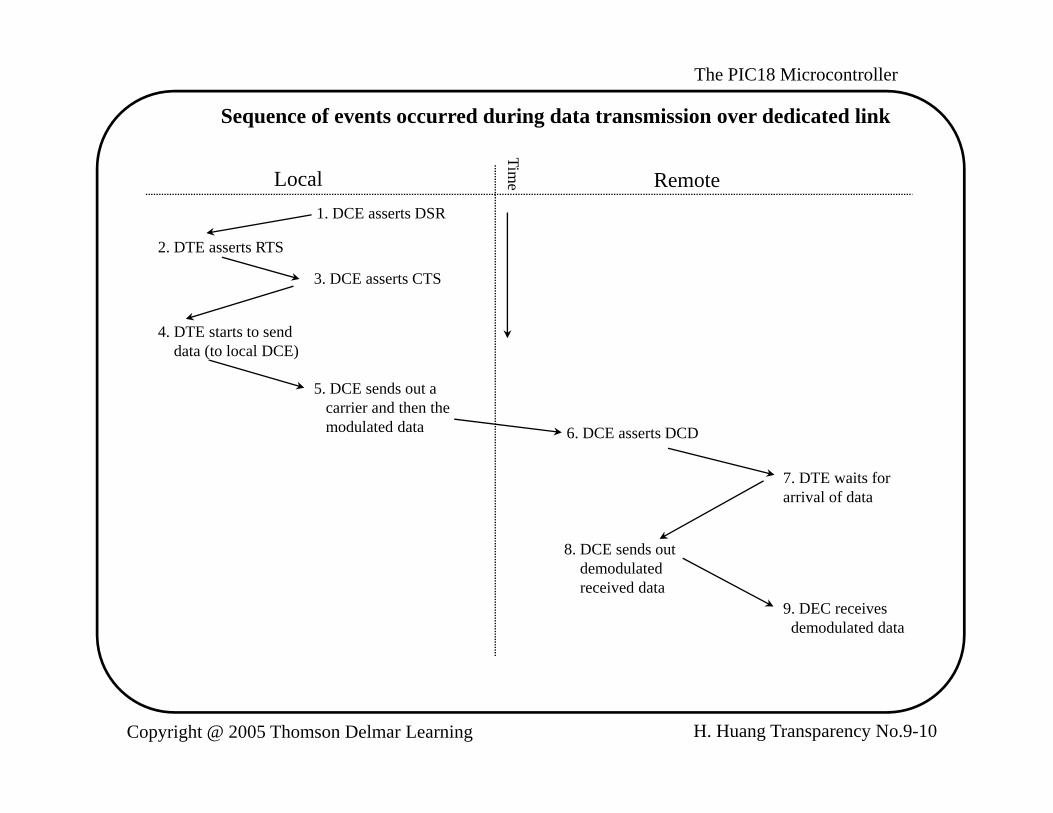
Sequence of events occurred during data transmission over dedicated link
Local Remote1. DCE asserts DSR
2. DTE asserts RTS
Time
3. DCE asserts CTS
4. DTE starts to senddata (to local DCE)data (to local DCE)
5. DCE sends out a carrier and then themodulated data 6. DCE asserts DCD
7. DTE waits for arrival of data
8. DCE sends outdemodulatedreceived data
9. DEC receivesdemodulated data
H. Huang Transparency No.9-10Copyright @ 2005 Thomson Delmar Learning

The PIC18 Microcontroller
Case 2: two DTEs exchange data over public phone lines
- Two additional signals are needed: DTR and RI- There are three phases in the data transmission:
1. Establishing the connection2. Data transmission3. Disconnection
TxRx
RING
TxRxRING
TxRx
RING
TxRxRING
Computer(DTE)
Computer(DTE)
Modem(DCE)
Modem(DCE)
RINGDCDCTSRTSDSRDTR
RINGDCDCTSRTSDSRDTR
RINGDCDCTSRTSDSRDTR
RINGDCDCTSRTSDSRDTR
Phone line
GND GND GND GND
Figure 9.3 Asynchronous connection over public phone line
H. Huang Transparency No.9-11Copyright @ 2005 Thomson Delmar Learning

The PIC18 Microcontroller
ti
Local Remote (receiving side)
ime
Connection establishment phase
(transmission side)
1 DTE asserts DTR1. DTE asserts DTR
2. DCE dials the phone number 3. DCE detects the ring
and asserts RING4. DTE asserts DTR
to accept the call
5. DCE sends out acarrier and asserts DSR6 DCE asserts DSR DSR6. DCE asserts DSR
and DCD and also sends out a carrierfor full duplex operation
7. DCE asserts DCD(full duplex operation)
H. Huang Transparency No.9-12Copyright @ 2005 Thomson Delmar Learning
The PIC18 Microcontroller
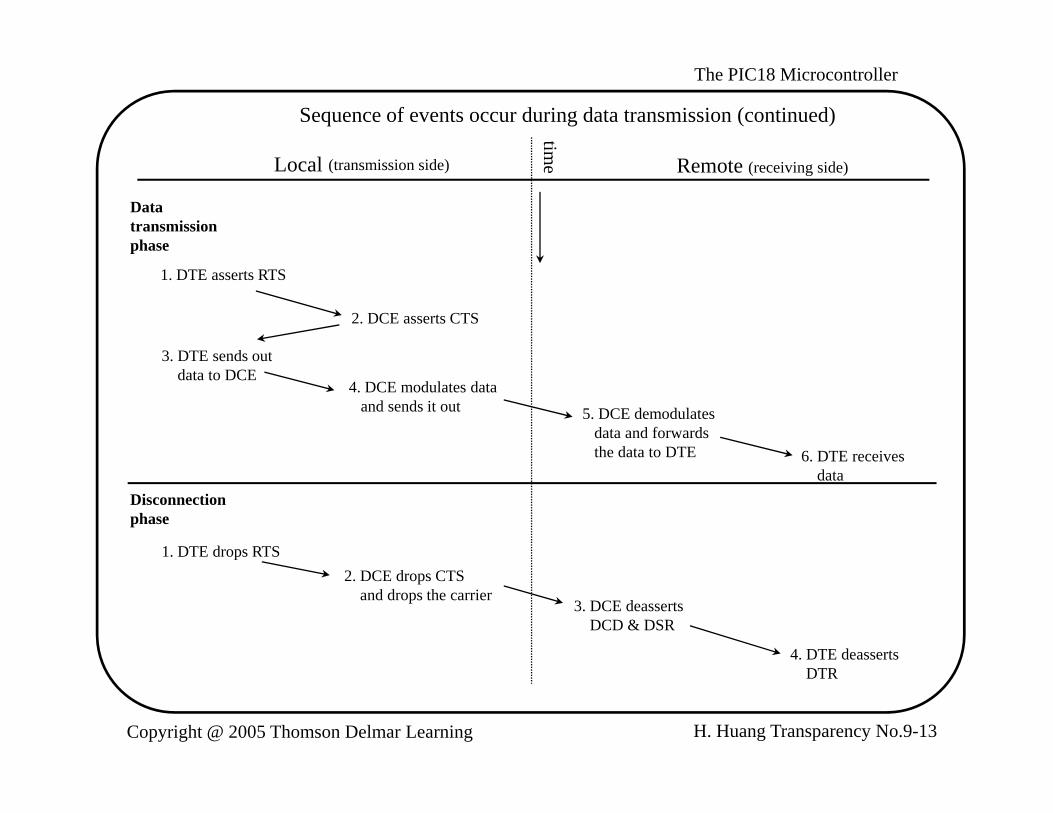
Sequence of events occur during data transmission (continued)
ti
Local Remote (receiving side)(transmission side)
ime
Data transmissionphasep
1. DTE asserts RTS
2. DCE asserts CTS
3 DTE sends out3. DTE sends outdata to DCE
4. DCE modulates dataand sends it out 5. DCE demodulates
data and forwards the data to DTE 6 DTE receives6. DTE receives
dataDisconnectionphase
1. DTE drops RTS2. DCE drops CTS
and drops the carrier3. DCE deasserts
DCD & DSR
4. DTE deasserts
H. Huang Transparency No.9-13Copyright @ 2005 Thomson Delmar Learning
DTR

The PIC18 Microcontroller
Data Format
- Data is transmitted character by character.- Each character is preceded by a start bit, followed by seven to nine data bits, and
terminated by one to two stop bits.- The receiver uses a clock signal with a frequency that is a multiple (usually 16) of the
data rate to sample the incoming data in order to detect the arrival of start bit and determine the bit values.
- A majority circuit takes three samples (bit 7, 8, and 9) in each bit time to detect the arrival of the start bit and determine the logic value of each data bit.
- In older designs, a character can be terminated by one, one and a half, two stop bits.- In new designs, only one stop bit is used.
Startbit
0 1 2 3 4 5 6 7 Stopbit 1
Stopbit 2bit 2
Figure 9.4 The format of a character
H. Huang Transparency No.9-14Copyright @ 2005 Thomson Delmar Learning

The PIC18 Microcontroller
Example 9.1 Sketch the output of the letter K when it is transmitted using the format of one start bit, eight data bits, and one stop bit. Solution: Letters are represented in ASCII code. The ASCII code of letter K is $4B (= 01001011). The format of the output of letter K is shown in Figure 9.6.
Start bit Stop bit
0 1 1 0 0 0 1 0 11
(a) output waveform at m icrocontroller interface
0 1 1 0 0 0 1 0 11
(b) output waveform at EIA232E interface
Figure 9.6 Data form at for letter kg
H. Huang Transparency No.9-15Copyright @ 2005 Thomson Delmar Learning

The PIC18 Microcontroller
Data Transmission ErrorsData Transmission Errors
1. Framing error- May occur due to clock synchronization problem- Can be detected by the missing stop bitCan be detected by the missing stop bit
2. Receiver overrun- May occur when the CPU did not read the received data for a while
3. Parity errors- Occur due to odd number of bits change valuesOccur due to odd number of bits change values
H. Huang Transparency No.9-16Copyright @ 2005 Thomson Delmar Learning

The PIC18 Microcontroller
Null Modem Connection- Used when two DTEs are located side by side and use the EIA232 interface to
exchange data.- Null modem connection connects signals in such a way to full two DTEs to think
that they connected through a modem.- In Figure 9.7, the signals on the same row of DTE1 and DTE2 are connected
together. - The cost of two modems are saved with Null modem connection.
Signal Name
FG (f d)
DB25 pin DB9 pin
DTE 1 DTE 2
DB9 pin DB25 pinSignal Name
1 1 FGFG (frame ground)TD (transmit data)RD (receive data)RTS (request to send)CTS (clear to send)SG (signal ground)
123457
-32785
-23875
132547
FGRDTDCTSRTSSG
Figure 9 7 Null Modem connection
( g g )DSR (data set ready)CD (carrier detect)DTR (data terminal ready)DTR (data terminal ready)
682020
6144
4416
202086
DTRDTRCDDSR
H. Huang Transparency No.9-17Copyright @ 2005 Thomson Delmar Learning
Figure 9.7 Null Modem connection
The PIC18 Microcontroller
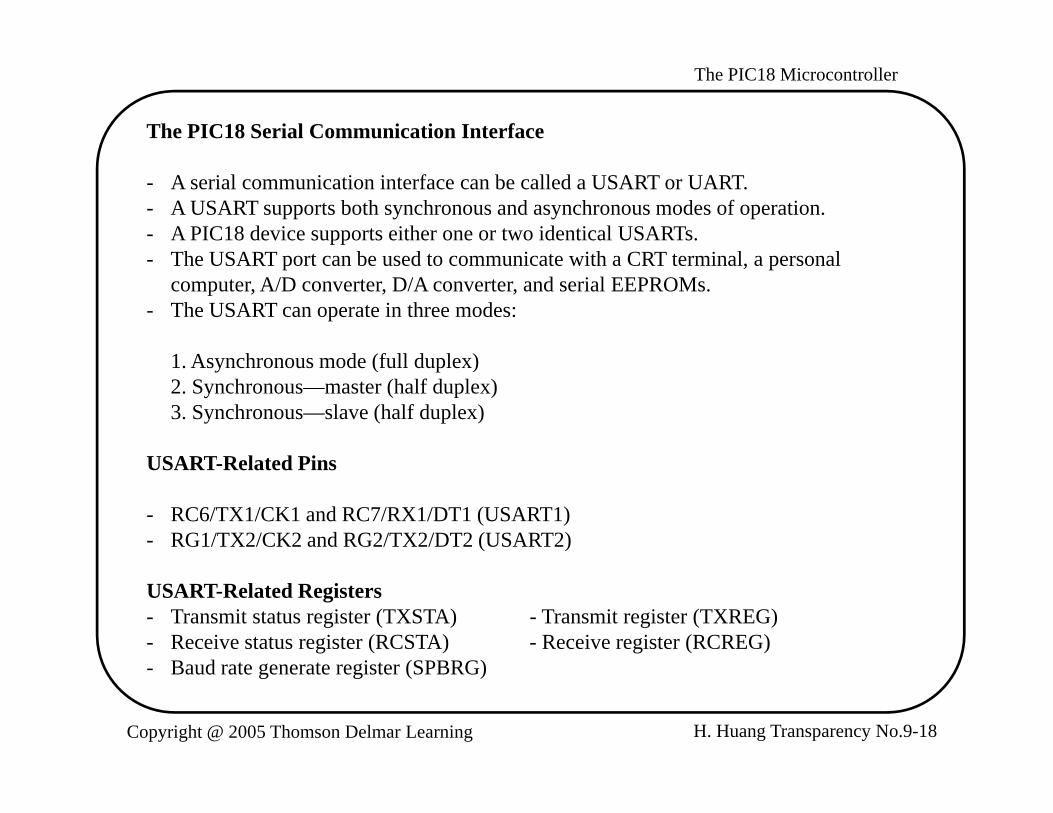
The PIC18 Serial Communication Interface
- A serial communication interface can be called a USART or UART.- A USART supports both synchronous and asynchronous modes of operation.- A PIC18 device supports either one or two identical USARTs.
Th USART b d i i h CRT i l l- The USART port can be used to communicate with a CRT terminal, a personal computer, A/D converter, D/A converter, and serial EEPROMs.
- The USART can operate in three modes:
1 A h d (f ll d l )1. Asynchronous mode (full duplex)2. Synchronous—master (half duplex)3. Synchronous—slave (half duplex)
USART R l t d PiUSART-Related Pins
- RC6/TX1/CK1 and RC7/RX1/DT1 (USART1)- RG1/TX2/CK2 and RG2/TX2/DT2 (USART2)
USART-Related Registers- Transmit status register (TXSTA) - Transmit register (TXREG)- Receive status register (RCSTA) - Receive register (RCREG)
B d t t i t (SPBRG)
H. Huang Transparency No.9-18Copyright @ 2005 Thomson Delmar Learning
- Baud rate generate register (SPBRG)
The PIC18 Microcontroller
7 6 5 4 3 2 1 0
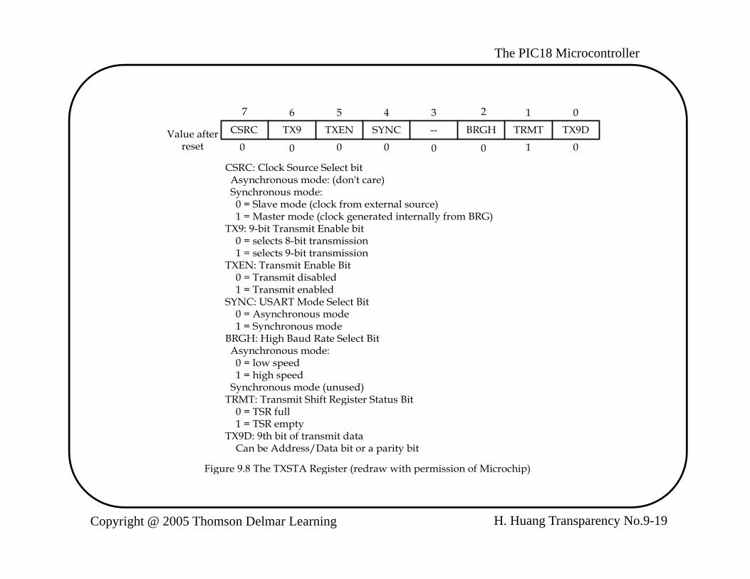
CSRC TX9 TXEN SYNC -- BRGH TRMT TX9DValue afterreset 0 0 0 0 0 0 1 0
CSRC: Clock Source Select bit Asynchronous mode: (don't care) Asynchronous mode: (don t care) Synchronous mode: 0 = Slave mode (clock from external source) 1 = Master mode (clock generated internally from BRG)TX9: 9-bit Transmit Enable bit 0 = selects 8-bit transmission 1 = selects 9 bit transmission 1 = selects 9-bit transmissionTXEN: Transmit Enable Bit 0 = Transmit disabled 1 = Transmit enabledSYNC: USART Mode Select Bit 0 = Asynchronous mode 1 = Synchronous mode 1 = Synchronous modeBRGH: High Baud Rate Select Bit Asynchronous mode: 0 = low speed 1 = high speed Synchronous mode (unused)TRMT: Transmit Shift Register Status BitTRMT: Transmit Shift Register Status Bit 0 = TSR full 1 = TSR emptyTX9D: 9th bit of transmit data Can be Address/Data bit or a parity bit
Figure 9.8 The TXSTA Register (redraw with permission of Microchip)
H. Huang Transparency No.9-19Copyright @ 2005 Thomson Delmar Learning
g g ( p p)
The PIC18 Microcontroller7 6 5 4 3 2 1 0
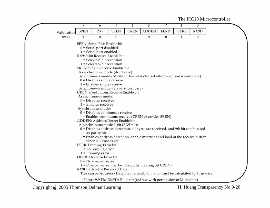
SPEN RX9 SREN CREN ADDEN FERR OERR RX9DValue afterreset 0 0 0 0 0 0 1 0
SPEN: Serial Port Enable bit 0 = Serial port disabled 1 = Serial port enabledRX9: 9-bit Receive Enable bit 0 = Selects 8-bit reception 1 = Selects 9-bit reception 1 Selects 9 bit receptionSREN: Single Receive Enable bit Asynchronous mode (don't care) Synchronous mode - Master (This bit is cleared after reception is complete): 0 = Disables single receive 1 = Enables single receive Synchronous mode - Slave: (don't care)
bl bCREN: Continuous Receive Enable bit Asynchronous mode: 0 = Disables receiver 1 = Enables receiver Synchronous mode: 0 = Disables continuous receive 1 = Enables continuous receive (CREN overrides SREN) 1 Enables continuous receive (CREN overrides SREN)ADDEN: Address Detect Enable bit Asynchronous mode 9-bit (RX9 = 1): 0 = Disables address detection, all bytes are received, and 9th bit can be used as parity bit. 1 = Enables address detection, enable interrupt and load of the receive buffer when RSR<8> is setFERR: Framing Error bit 0 = no framing error 1 = Framing errorOERR: Overrun Error bit 0 = No overrun error 1 = Overrun error (can be cleared by clearing bit CREN)RX9D: 9th bit of Received Data
H. Huang Transparency No.9-20Copyright @ 2005 Thomson Delmar Learning
RX9D: 9th bit of Received Data This can be Address/Data bit or a parity bit, and must be calculated by firmware.
Figure 9.9 The RXSTA Register (redraw with permission of Microchip)

The PIC18 Microcontroller
- The shift clock for the USART is generated by the baud rate generator (SPBRG).- In asynchronous mode, the BRGH bit of the TXSTA register also involves in the baud
rate computation.- The baud rate is computed using the formula shown in Table 9.2.
Table 9.2 Formula for baud rate
SYNC bit BRGH = 0 (low speed) BRGH = 1 (high speed)
01
(Asynchronous) Baud rate = FOSC/(64 (X+1))(Synchronous) Baud Rate = FOSC/(4(X+1))
Baud Rate = FOSC/(16(X+1))N/A
Note. X is the content of the SPBRG register
In asynchronous mode:y When BRGH = 1, SPBRG = (FOSC/(16 x baud rate)) - 1 When BRGH = 0, SPBRG = (FOSC/(64 x baud rate)) - 1In synchronous mode: SPBRG = (FOSC/(4 x baud rate)) - 1
H. Huang Transparency No.9-21Copyright @ 2005 Thomson Delmar Learning
The PIC18 Microcontroller
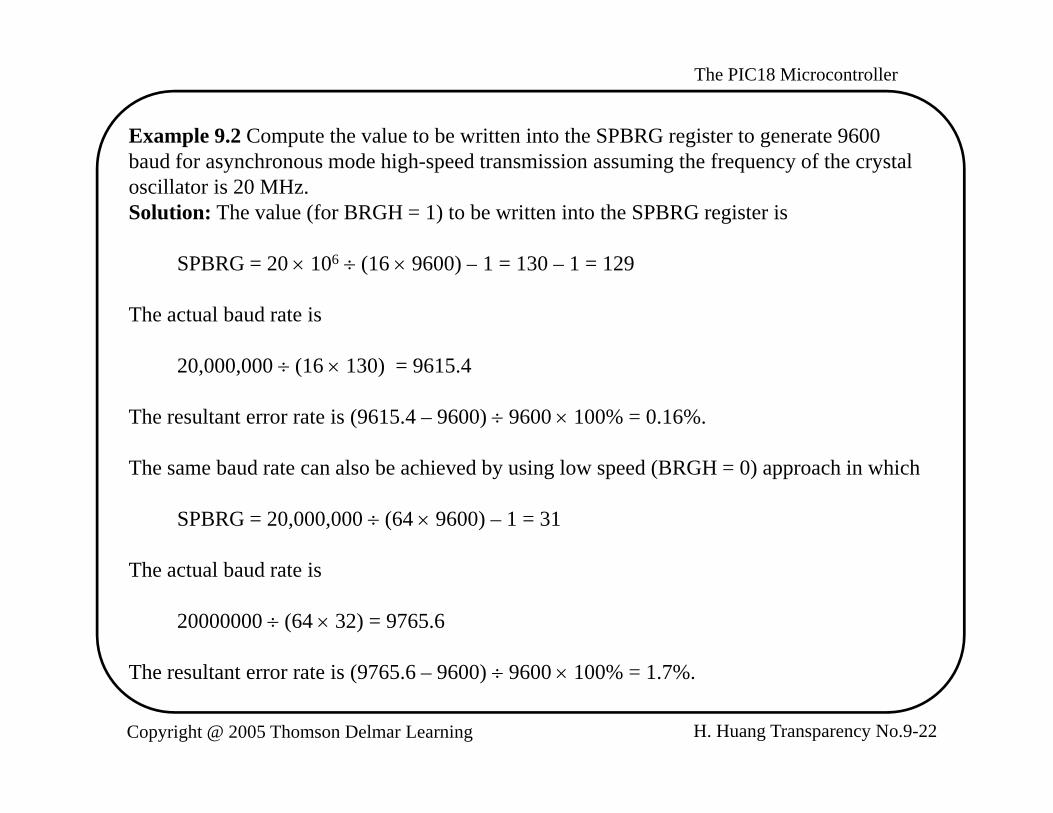
Example 9.2 Compute the value to be written into the SPBRG register to generate 9600 baud for asynchronous mode high-speed transmission assuming the frequency of the crystal oscillator is 20 MHz. Solution: The value (for BRGH = 1) to be written into the SPBRG register is
SPBRG = 20 106 (16 9600) – 1 = 130 – 1 = 129
The actual baud rate is
20,000,000 (16 130) = 9615.4
The resultant error rate is (9615.4 – 9600) 9600 100% = 0.16%.
The same baud rate can also be achieved by using low speed (BRGH = 0) approach in which
SPBRG = 20,000,000 (64 9600) – 1 = 31
The actual baud rate is
20000000 (64 32) = 9765.6
H. Huang Transparency No.9-22Copyright @ 2005 Thomson Delmar Learning
The resultant error rate is (9765.6 – 9600) 9600 100% = 1.7%.

The PIC18 Microcontroller
USART Asynchronous ModeD f i bi i h i d bi d bi- Data format is one start bit, eight or nine data bits, and one stop bit.
- The least significant bit is transmitted first- The transmitter and receiver are independent but use the same data format and baud
rate. A h d i d i l d- Asynchronous mode is stopped in sleep mode.
- The diagram of the transmitter block is shown in Figure 9.10.
Data Bus
TXREGy Register
8
(8) (0)msb lsb
Pin Buffer
TXyIFTXyIE
Interrupt (8) (0)...TSR Register
and ControlTX pin
TRMT SPEN
Interrupt
TRMT SPEN
TX9
TX9D
Baud Rate CKTXEN
SPBRGy
Baud Rate GeneratorN t 1 2
H. Huang Transparency No.9-23Copyright @ 2005 Thomson Delmar Learning
Figure 9.10 USARTy Transmit block diagram (redraw with permission of Microchip)
Note. y = 1 or 2

The PIC18 Microcontroller
Example 9.3 Write a subroutine to configure the USART1 transmitter to transmit data in asynchronous mode using 8-bit data format, disable interrupt, set baud rate to 9600. Assume the frequency of the crystal oscillator is 16 MHz. Solution:- Write the value of 0x24 into the TXSTA1 register- Configure TX1 pin for output, RX1 pin for input:
usart1_open movlw 0x24movwf TXSTA1movlw D’103’ ; set baud rate to 9600movwf SPBRG1 ; “bsf TRISC,RC7 ; configure RX1 pin for inputbcf TRISC,RC6 ; configure TX1 pin for outputbcf PIE1,TXIE ; disable transmit interruptbsf RCSTA1,SPEN ; enable USART1return
H. Huang Transparency No.9-24Copyright @ 2005 Thomson Delmar Learning

The PIC18 Microcontroller
In C language,
void usart1_open(void){
TXSTA1 = 0x24;SPBRG1 = 103;TRISCbits.RC7 = 1; /* configure RX1 pin for input */TRISCbits.RC6 = 0; /* configure TX1 pin for output */PIE1bits.TXIE = 0; /* disable transmit interrupt */RCSTA1bits.SPEN = 1; /* enable USART port */
}
H. Huang Transparency No.9-25Copyright @ 2005 Thomson Delmar Learning

The PIC18 Microcontroller
Example 9.4 Write a subroutine to output the character in WREG to USART1 using p W p W G US gthe polling method.Solution:- Data can be sent to the transmitter only when the transmit register is empty.
putc_usart1 btfss PIR1,TXIF,A ; wait until TXIF flag is set before outputbra putc_usart1movwf TXREG1return
In C language,
void putc usart1 (char xc);p _ ( );{
while (!PIR1bits.TX1IF);TXREG1 = xc;
}}
H. Huang Transparency No.9-26Copyright @ 2005 Thomson Delmar Learning

The PIC18 Microcontroller
Example 9.5 Write a subroutine to output a string (in program memory) pointed to by TBLPTR and terminated by a NULL character from USART1. Solution:
; *******************************************************************Th f ll i b ti t t th t i i t d t b TBLPTR It i ll d; The following subroutine outputs the string pointed to by TBLPTR. It is called
; with fast save enabled.; *******************************************************************puts_usart1 TBLRD*+ ; read one character into TABLAT
mo f TABLAT W A ; place the character in WREGmovf TABLAT,W,A ; place the character in WREGbz done ; is it a NULL character?call putc_usart1 ; not NULL, outputbra puts_usart1 ; continue
done return fastdone return fast
In C language,
void puts usart1 (unsigned rom char *cptr)void puts_usart1 (unsigned rom char *cptr){
while(*cptr)putc_usart1 (*cptr++);
}
H. Huang Transparency No.9-27Copyright @ 2005 Thomson Delmar Learning
}

The PIC18 Microcontroller
x64 Baud rate CLK
CREN OERR FERR
SPBRG
Baud rate generator
or STOP START(8) 7 ...
msb lsbRSR register
0
DataRecovery
Pin Bufferand Control
RX pin RX9
RX9D RCREG R i t
FIFO
SPEN
RX9D
8
RCREG Register
D B
RCIFRCIE
interrupt
Data Bus
Figure 9.11 USART receive block diagram (redraw with permission of Microchip)
H. Huang Transparency No.9-28Copyright @ 2005 Thomson Delmar Learning
The PIC18 Microcontroller
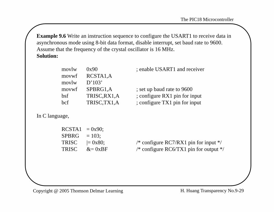
Example 9.6 Write an instruction sequence to configure the USART1 to receive data in asynchronous mode using 8-bit data format, disable interrupt, set baud rate to 9600. Assume that the frequency of the crystal oscillator is 16 MHz. Solution:
movlw 0x90 ; enable USART1 and receivermovwf RCSTA1,Amovlw D’103’movwf SPBRG1,A ; set up baud rate to 9600bsf TRISC,RX1,A ; configure RX1 pin for inputbcf TRISC,TX1,A ; configure TX1 pin for input
In C language,
RCSTA1 = 0x90;SPBRG = 103;TRISC |= 0x80; /* configure RC7/RX1 pin for input */ TRISC &= 0xBF /* configure RC6/TX1 pin for output */
H. Huang Transparency No.9-29Copyright @ 2005 Thomson Delmar Learning

The PIC18 Microcontroller
Example 9.7 Write a subroutine to read a character from USART1 and return the p W UScharacter in WREG using the polling method. Ignore any errors. Solution: A new character is received if the RCIF flag of the PIR1 register is set to 1.
getc_usart1 btfss PIR1,RCIF ; make sure a new character has been receivedb t t1bra getc_usart1movf RCREG1,W ; read the characterreturn FAST
I C lIn C language,
unsigned char getc_usart1 (void) {
hil (!PIR1bit RCIF)while (!PIR1bits.RCIF);return RCREG1;
}
H. Huang Transparency No.9-30Copyright @ 2005 Thomson Delmar Learning

The PIC18 Microcontroller
Example 9.8 Write a subroutine to read a string from the USART1 and store the stringExample 9.8 Write a subroutine to read a string from the USART1 and store the string in a buffer pointed to by FSR0.Solution:The string from the USART port is terminated by a carriage return character.
CR equ 0x0Dgets_usart1 call getc_usart1
movwf INDF0 ; save the character in buffersublw CRbz doneclrf PREINC0,F ; move the pointergoto gets_usart1
done clrf INDF0 ; terminate the string with a NULL charactergreturn
H. Huang Transparency No.9-31Copyright @ 2005 Thomson Delmar Learning
The PIC18 Microcontroller
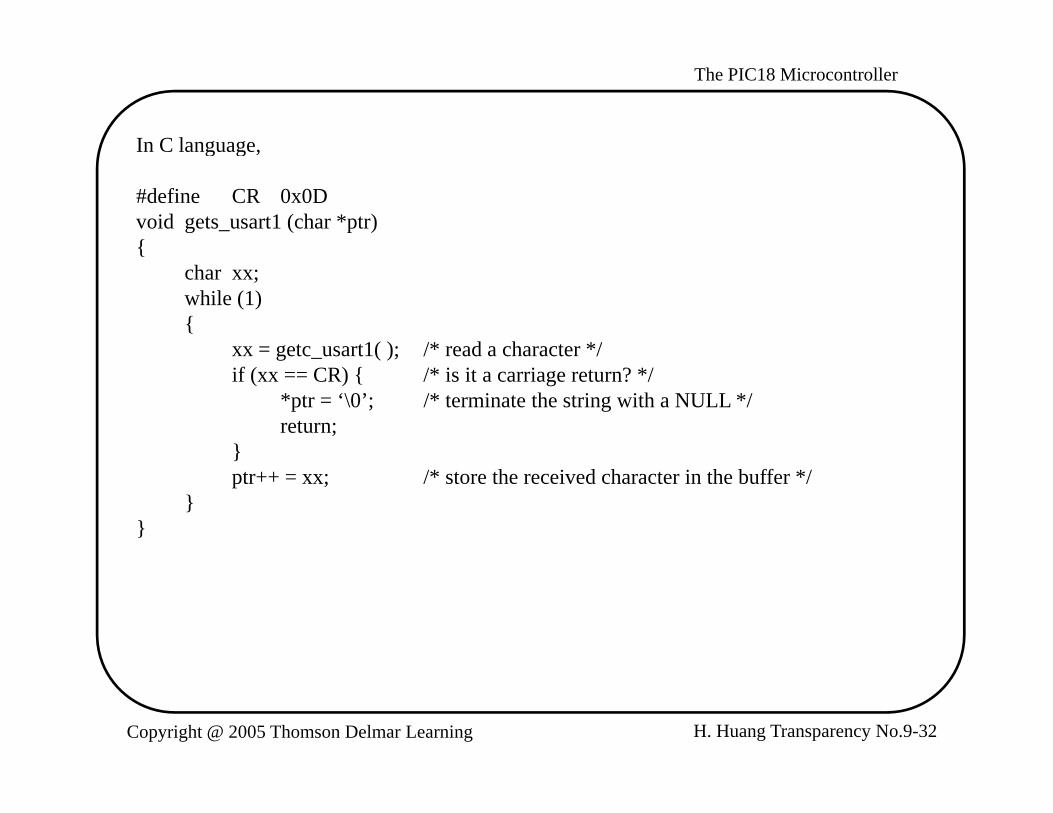
In C language,In C language,
#define CR 0x0Dvoid gets_usart1 (char *ptr){{
char xx;while (1){
xx = getc usart1( ); /* read a character */xx getc_usart1( ); / read a character /if (xx == CR) { /* is it a carriage return? */
*ptr = ‘\0’; /* terminate the string with a NULL */return;
}}ptr++ = xx; /* store the received character in the buffer */
}}
H. Huang Transparency No.9-32Copyright @ 2005 Thomson Delmar Learning

The PIC18 Microcontroller
Flow Control of USART in Asynchronous Modey
- In some circumstances, the software cannot read the received data and needs to inform the transmitter to stop.
- In some other situation, the transmitter may need to be told to suspend transmission , y pbecause the receiver is too busy to read data.
- Both situations are handled by flow control.- There are two flow control methods: hardware and XON/XOFF.- XON and XOFF are two standard ASCII characters.- The ASCII code for XON and XOFF are 0x11 and 0x13, respectively.- Whenever a microcontroller cannot handle the incoming data, it sends the XOFF to
the transmitter. - When the microcontroller can handle incoming characters, it sends out XON g
character.
H. Huang Transparency No.9-33Copyright @ 2005 Thomson Delmar Learning
The PIC18 Microcontroller
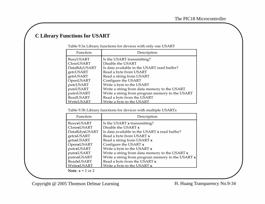
C Library Functions for USARTy
Function Description
BusyUSARTCloseUSART
Is the USART transmitting?Disable the USART
Table 9.3a Library functions for devices with only one USART
CloseUSARTDataRdyUSARTgetcUSARTgetsUSARTOpenUSARTputcUSARTputsUSART
Disable the USARTIs data available in the USART read buffer?Read a byte from USARTRead a string from USARTConfigure the USARTWrite a byte to the USARTWrite a string from data memory to the USARTputsUSART
putrsUSARTReadUSARTWriteUSART
Write a string from data memory to the USARTWrite a string from program memory to the USARTRead a byte from the USARTWrite a byte to the USART
Table 9.3b Library functions for devices with multiple USARTs
Function Description
BusyxUSARTClosexUSARTDataRdyxUSARTgetcxUSARTgetsxUSART
Is the USART x transmitting?Disable the USART xIs data available in the USART x read buffer?Read a byte from USART xRead a string from USART xgetsxUSART
OpenxUSARTputcxUSARTputsxUSARTputrsxUSARTReadxUSARTWritexUSART
Read a string from USART xConfigure the USART xWrite a byte to the USART xWrite a string from data memory to the USART xWrite a string from program memory to the USART xRead a byte from the USART xWrite a byte to the USART x
H. Huang Transparency No.9-34Copyright @ 2005 Thomson Delmar Learning
WritexUSART Write a byte to the USART xNote. x = 1 or 2
The PIC18 Microcontroller
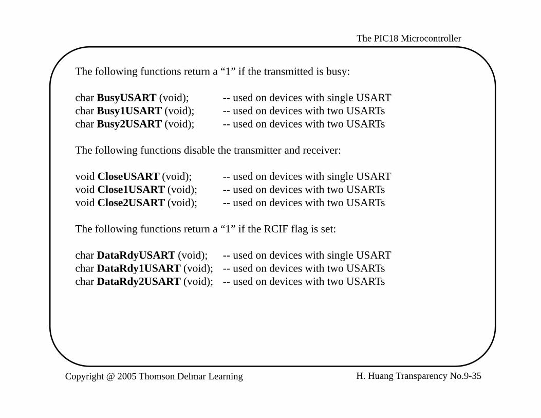
The following functions return a “1” if the transmitted is busy:
char BusyUSART (void); -- used on devices with single USARTchar Busy1USART (void); -- used on devices with two USARTschar Busy2USART (void); -- used on devices with two USARTs
The following functions disable the transmitter and receiver:
void CloseUSART (void); -- used on devices with single USARTvoid Close1USART (void); -- used on devices with two USARTsvoid Close2USART (void); -- used on devices with two USARTs
The following functions return a “1” if the RCIF flag is set:
char DataRdyUSART (void); -- used on devices with single USARTchar DataRdy1USART (void); -- used on devices with two USARTschar DataRdy2USART (void); -- used on devices with two USARTs
H. Huang Transparency No.9-35Copyright @ 2005 Thomson Delmar Learning

The PIC18 Microcontroller
Any one of the following functions read a byte from the receive buffer including the 9th
bit:
char getcUSART (void); -- used on devices with single USARTchar getc1USART (void); -- used on devices with two USARTschar getc2USART (void); -- used on devices with two USARTschar ReadUSART (void); -- used on devices with single USARTchar Read1USART (void); -- used on devices with two USARTschar Read2USART (void); -- used on devices with two USARTs
The following functions read the specified number of byes from the USART module and save the string in a buffer:
void getsUSART (char *buffer, unsigned len); -- for devices with single USARTchar gets1USART (char *buffer, unsigned len); -- for devices with two USARTchar gets2USART (char *buffer, unsigned len); -- for devices with two USART
H. Huang Transparency No.9-36Copyright @ 2005 Thomson Delmar Learning
The PIC18 Microcontroller
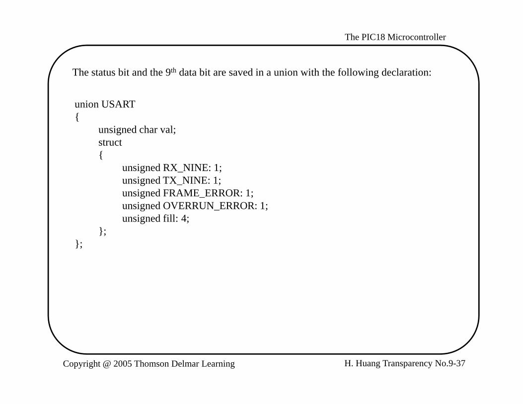
The status bit and the 9th data bit are saved in a union with the following declaration:The status bit and the 9 data bit are saved in a union with the following declaration:
union USART{
i d h lunsigned char val;struct {
unsigned RX_NINE: 1;i d 1unsigned TX_NINE: 1;
unsigned FRAME_ERROR: 1;unsigned OVERRUN_ERROR: 1;unsigned fill: 4;
}};};
H. Huang Transparency No.9-37Copyright @ 2005 Thomson Delmar Learning

The PIC18 Microcontroller
The following functions write one character to the transmit buffer:
char putcUSART (char data); -- used on devices with single USARTchar putc1USART (char data); -- used on devices with two USARTschar putc2USART (char data); -- used on devices with two USARTschar WriteUSART (char data); -- used on devices with single USARTchar Write1USART (char data); -- used on devices with two USARTschar Write2USART (char data); -- used on devices with two USARTs
The following functions output a string in program memory to the USART module:
void putrsUSART (const rom char *data); -- used on devices with single USARTvoid putrs1USART (const rom char *data); -- used on devices with two USARTsvoid putrs2USART (const rom char *data); -- used on devices with two USARTs
The following functions output a string in data memory to the USART module:
void putsUSART (char *data); -- used on devices with single USARTvoid puts1USART (char *data); -- used on devices with two USARTsvoid puts2USART (char *data); -- used on devices with two USARTs
H. Huang Transparency No.9-38Copyright @ 2005 Thomson Delmar Learning

The PIC18 Microcontroller
The following functions configured the specified USART module:
void OpenUSART (unsigned char config, char spbrg); -- used on devices with single USART
void Open1USART (unsigned char config,char spbrg); -- used on devices with two USARTs
void Open2USART (unsigned char config,char spbrg); -- used on devices with two USARTs
The config parameter is defined by ANDing the following parameters:
Interrupt on Transmission:USART_TX_INT_ON Transmit interrupt ONUSART_TX_INT_OFF Transmit interrupt OFF
Interrupt on Reception:USART_RX_INT_ON Receive interrupt ONUSART_RX_INT_OFF Receive interrupt OFF
USART Mode:USART_ASYNCH_MODE Asynchronous modeUSART_SYNCH_MODE Synchronous mode
H. Huang Transparency No.9-39Copyright @ 2005 Thomson Delmar Learning

The PIC18 Microcontroller
Transmission Width:USART_EIGHT_BIT 8-bit transmit/receiveUSART_NINE_BIT 9-bit transmit/receive
Slave/Master Select:USART SYNC SLAVE Synchronous slave mode_ _ yUSART_SYNC_MASTER Synchronous master mode
Reception mode:USART_SINGLE_RX Single receptionUSART CONT RX Continuous reception_ _ p
Baud rate: (applied to asynchronous mode only)USART_BRGH_HIGH High baud rateUSART_BRGH_LOW Low baud rate
The spbrg is the value to be written into the SPBRG register to set the baud rate.
An example, Open1USART (USART TX INT OFF & USART RX INT OFF &p ( _ _ _ _ _ _
USART_ASYNCH_MODE & USART_EIGHT_BIT &USART_BRGH_HIGH, 103);
H. Huang Transparency No.9-40Copyright @ 2005 Thomson Delmar Learning
The PIC18 Microcontroller
Interface Asynchronous Mode USART with EIA232y
- The USART in asynchronous mode is mainly used with the EIA232 interface.- The USART module uses 0 and 5V to represent logic 0 and 1 and hence cannot be
connected to the EIA232 circuit directly.y- A circuit called EIA232 transceiver is needed to translate the voltage levels of the
USART to and from the voltage levels of the EIA232 interface.- EIA232 transceivers are available from many vendors. - LT1080/1081 from Linear Technology, ST232 from SGS Thompson, the ICL232 gy, p ,
from Intersil, the MAX232 from MAXIM, and the DS14C232 from National Semiconductor are examples of the EIA232 transceiver. These EIA232 transceivers operate with a 5-V power supply.
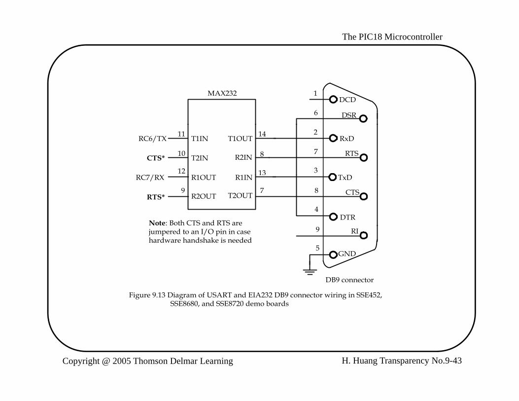
- The pin assignment of the MAX232 is shown in Figure 9.12.p g g- The circuit connection of the MAX232 with the PIC18 is shown in Figure 9.13.
H. Huang Transparency No.9-41Copyright @ 2005 Thomson Delmar Learning

The PIC18 Microcontroller+5 V
16+-
6.3V
C40.1F0.1F
1
3
4
16
V+
V-
2
6
VCCC1+
C1-
C2+
C1
0.1F
+5 V
14T1 T1
5
V0.1F
C2+
C2-
DC-to-DC ConverterC2 C30.1F
+5 V EIA-232-Eoutputs
TTL/CMOSinputs
TTL/CMOSinputs
10
11
7
14T1IN
T2IN
T1OUT
T2OUT
D1
D2
EIA-232-Einputs
p
TTL/CMOSoutputs
12 13R1IN
5K
R1OUT R1
TTL/CMOSoutputs
9
15
8R2IN
5K
R2OUT
GND
R2
H. Huang Transparency No.9-42Copyright @ 2005 Thomson Delmar Learning
Figure 9.12 Pin assignments and connections of the MAX232A
15
The PIC18 Microcontroller
1
6
DCD
DSR
MAX232
RC6/TX
RC7/RX
CTS*
T1IN
T2IN
R1OUT
T1OUT
R1IN
R2IN
11
10
12
8
13
14 2
7
3
RxD
RTS
T DRC7/RX
Note: Both CTS and RTS are
RTS*
R1OUT
R2OUT T2OUT
R1IN
9 7 8
4
TxD
CTS
DTR
jumpered to an I/O pin in casehardware handshake is needed
9
5
RI
GND
DB9 connector
Figure 9.13 Diagram of USART and EIA232 DB9 connector wiring in SSE452, SSE8680, and SSE8720 demo boards
H. Huang Transparency No.9-43Copyright @ 2005 Thomson Delmar Learning
The PIC18 Microcontroller
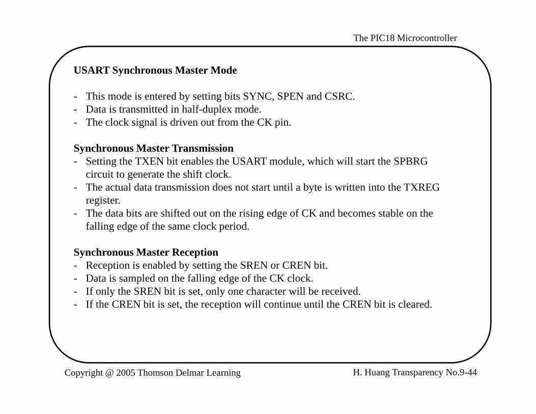
USART Synchronous Master Mode
- This mode is entered by setting bits SYNC, SPEN and CSRC.- Data is transmitted in half-duplex mode.- The clock signal is driven out from the CK pin.
Synchronous Master Transmission- Setting the TXEN bit enables the USART module, which will start the SPBRG
circuit to generate the shift clock.- The actual data transmission does not start until a byte is written into the TXREG
register.- The data bits are shifted out on the rising edge of CK and becomes stable on the
falling edge of the same clock period.
Synchronous Master Reception- Reception is enabled by setting the SREN or CREN bit.- Data is sampled on the falling edge of the CK clock.- If only the SREN bit is set, only one character will be received.- If the CREN bit is set, the reception will continue until the CREN bit is cleared.
H. Huang Transparency No.9-44Copyright @ 2005 Thomson Delmar Learning

The PIC18 Microcontroller
Q1
Q2
Q3
Q4
Q1
Q2
Q3
Q4
Q1
Q2
Q3
Q4
Q1
Q2
Q3
Q4
Q1
Q2
Q3
Q4
Q1
Q2
Q3
Q4
Q1
Q2
Q3
Q4
Q1
Q2
Q3
Q4
Q2
Q3
Q4
Q1
bit 0 bit 1 bit 2 bit 3 bit 4 bit 5 bit 6 bit 7RC/RX/DT
RC6/TX/CK
Write toTXREG
TXIF bit
TRMT bit
TXEN bit
Figure 9.14 USART transmission in synchronous master mode (redraw with permission of Microchip)
H. Huang Transparency No.9-45Copyright @ 2005 Thomson Delmar Learning

The PIC18 Microcontroller
bit 0 bit 1 bit 2 bit 3 bit 4 bit 5 bit 6 bit 7RC/RX/DT
Q1
Q2
Q3
Q4
Q1
Q2
Q3
Q4
Q1
Q2
Q3
Q4
Q1
Q2
Q3
Q4
Q1
Q2
Q3
Q4
Q1
Q2
Q3
Q4
Q1
Q2
Q3
Q4
Q1
Q2
Q3
Q4
Q2
Q3
Q4
Q1
RC6/TX/CK
Write toWrite toSREN
SREN bit
CREN bit
RCIF bit(interrupt)
'0'
( p )
Figure 9.15 USART reception in synchronous master mode (SREN=1) (redraw with permission of Microchip)
H. Huang Transparency No.9-46Copyright @ 2005 Thomson Delmar Learning

The PIC18 Microcontroller
USART Synchronous Slave ModeUS Sy c o ous S ve ode
- Shift clock is provided by external device and is input to the CK pin.- Slave mode is entered by setting both the SYNC and SPEN bits and clearing the
CSRC bit.
Synchronous Slave Transmission- The shift clock signal is an input from the CK pin.- CREN bit must be cleared.- Transmission is enabled by setting the TXEN bit.- Transmission is started by loading data into the TXREG register.
Synchronous Slave Receptiony p- Clock source is an input from the CK pin.- When the RCIF flag is set, read the RCREG register to get the lower 8 bits.- If 9-bit reception is enabled, then read the 9th bit from the RCSTA register.- If there is any error, then clear the error by clearing the CREN bit.y , y g
H. Huang Transparency No.9-47Copyright @ 2005 Thomson Delmar Learning
The PIC18 Microcontroller
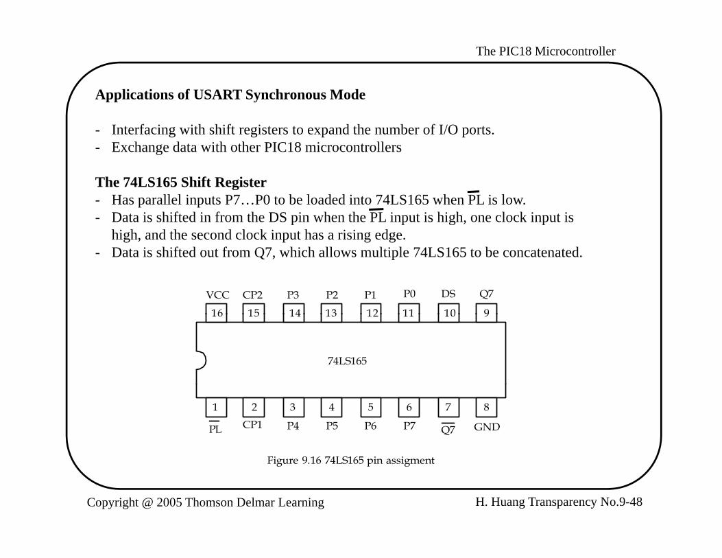
Applications of USART Synchronous Mode
- Interfacing with shift registers to expand the number of I/O ports.- Exchange data with other PIC18 microcontrollers
The 74LS165 Shift Register- Has parallel inputs P7…P0 to be loaded into 74LS165 when PL is low.- Data is shifted in from the DS pin when the PL input is high, one clock input is
high, and the second clock input has a rising edge.- Data is shifted out from Q7, which allows multiple 74LS165 to be concatenated.
16 15 14 13 12 11 10 9
VCC CP2 P3 P2 P1 P0 DS Q7
16 15 14 13 12 11 10 9
74LS165
87654321
PL CP1 P4 P5 P6 P7 Q7 GND
H. Huang Transparency No.9-48Copyright @ 2005 Thomson Delmar Learning
Figure 9.16 74LS165 pin assigment

The PIC18 Microcontroller
T bl 9 4 T th t bl f 74LS165Table 9.4 Truth table of 74LS165
PLCP Contents
1 2 Q0 Q1 Q2 Q3 Q4 Q5 Q6 Q7Response
LH
XL
X
P0DS
P1Q0
P2Q1
P3Q2
P4Q3
P5Q4
P6Q5
P7Q6
Parallel loadright shiftH
HHH
LH
LH
DSQ0DSQ0
Q0Q1Q0Q1
Q1Q2Q1Q2
Q2Q3Q2Q3
Q3Q4Q3Q4
Q4Q5Q4Q5
Q5Q6Q5Q6
Q6Q7Q6Q7
right shiftno changeright shiftno change
Example 9.9 Show the circuit connection for using one 74LS165 to add an input port to the PIC18F8720 using the USART2 in synchronous master mode. Write a subroutine to configure the USART2 properly and a subroutine to shift one byte of data assuming that the PIC18F8720 is running with a 16-MHz crystal oscillator.data assuming that the PIC18F8720 is running with a 16 MHz crystal oscillator. Assume that the user uses eight switches to set the value to be input and uses INT1 interrupt to inform the arrival of data. Solution:1. Use the synchronous master mode to interface with the 74LS165.1. Use the synchronous master mode to interface with the 74LS165.2. Configure RG2/DT2 and RG1/CK2 for input and output, respectively.3. Set baud rate to 1 Mbps4. Enable INT1 interrupt5. Circuit connection is shown in Figure 9.17.
H. Huang Transparency No.9-49Copyright @ 2005 Thomson Delmar Learning
5. Circuit connection is shown in Figure 9.17.

The PIC18 Microcontroller
PIC18F8720 74LS165 5V
RG2/DT2
RG1/CK CP2
Q7
P0
P1
P2
VCC
D7
D6
D5
INT1
CP1
DSP3
P4
P5
P6
D4
D3
D2
D1
connectedto DIP
switchesdebounced
switch
PLRB4 P7
GND
D0
Figure 9 17 Circuit connection between the PIC18F8720 and 74LS165Figure 9.17 Circuit connection between the PIC18F8720 and 74LS165
H. Huang Transparency No.9-50Copyright @ 2005 Thomson Delmar Learning

The PIC18 Microcontroller
Procedure for inputting data from 74LS165p g
1. Set up a new value to P0 to P7 using the DIP switches.2. Press the debounced switch to request an interrupt using the INT1 pin.3. The INT1 interrupt service routine reads in the data from the RCREG2.p
#include <p18F8720.inc>rcv_buf set 0 ; buffer to hold the received byte
org 0x00ggoto startorg 0x08goto hi_ISRorg 0x18gretfie
start bcf TRISG,RG1,A ; configure CK2 pin for outputbsf TRISG,RG2,A ; configure DT2 pin for inputcall open usart2p _call open_INT1
forever nopbra forever
H. Huang Transparency No.9-51Copyright @ 2005 Thomson Delmar Learning

The PIC18 Microcontroller
; *****************************************************************; The following function configures USART2 to operate in ; synchronous master mode with baud rate set to 10**6.; *****************************************************************open_usart2 movlw 0x03p _
movwf SPBRG2,A ; set the shift rate to 1MHzmovlw 0x90 ; set synchronous master modemovwf TXSTA2,A ; "movlw 0x80 ; enable USART2 and disable movwf RCSTA2,A ; receptionreturn
; ************************************************************************; The following subroutine configures INT1 to high priority and; then enable its interrupt.; ************************************************************************open_INT1 bsf RCON,IPEN,A ; enable priority interrupt
movlw 0x48 ; set INT1 interrupt to high priority,movwf INTCON3,A ; and then enable INT1 interruptmovlw 0xC0 ; enable global interruptmovwf INTCON ; "return
H. Huang Transparency No.9-52Copyright @ 2005 Thomson Delmar Learning

The PIC18 Microcontroller
; *************************************************************************; *************************************************************************; The high priority interrupt service routine makes sure ; that the interrupt is caused by usart2 INT1IF and then enable; reception by setting SPEN bit. Wait until a byte is received.; *************************************************************************; *************************************************************************hi_ISR btfss INTCON3,INT1IF,A ; is interrupt caused by INT1?
retfie ; interrupt is not caused by INT1bcf INTCON3,INT1IF,A ; clear INT1IFbcf PORTB RB4 A ; load data into 74LS165bcf PORTB,RB4,A ; load data into 74LS165nop ; "bsf PORTB,RB4,A ; disable new data into 74LS165bcf PIR3,RC2IF,A ; bsf RCSTA2 SREN A ; enable single reception from USART2bsf RCSTA2,SREN,A ; enable single reception from USART2
wait btfss PIR3,RC2IF,A ; wait for the arrival of a bytebra waitmovff RCREG2,rcv_bufretfieretfie end
H. Huang Transparency No.9-53Copyright @ 2005 Thomson Delmar Learning
The PIC18 Microcontroller
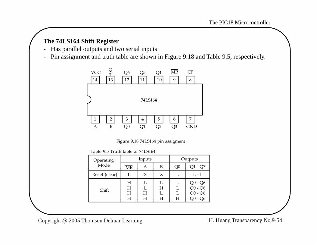
The 74LS164 Shift Register- Has parallel outputs and two serial inputs - Pin assignment and truth table are shown in Figure 9.18 and Table 9.5, respectively.
VCC Q7 Q6 Q5 Q4 CPMR
14 13 12 11 10 9 87
74LS164
7654321
A B Q0 Q1 Q2 Q3 GND
Figure 9.18 74LS164 pin assigment
Table 9.5 Truth table of 74LS164
OperatingMode
Inputs Outputs
MR A B Q0 Q1 - Q7MRReset (clear) L X X L L - L
Shift
HHHH
LLHH
LHLH
LLLH
Q0 - Q6Q0 - Q6Q0 - Q6Q0 - Q6
H. Huang Transparency No.9-54Copyright @ 2005 Thomson Delmar Learning
H H H H Q0 Q6

The PIC18 Microcontroller
Example 9.10 Show the circuit connection if you are to use one 74LS164 to add an p youtput port to the PIC18F8720 using the USART2 module in synchronous master mode. Write a subroutine to shift out one byte of data assuming that the PIC18F8720 is running with a 16-MHz crystal oscillator. The user may uses Q7..Q0 to drive LEDs. Solution: The circuit connection is shown in Figure 9.19. Q7…Q0 should be used as g Q Qthe least significant bit to the most significant bit.
PIC18F8720 74LS164 5V
RG2/DT2
RG1/CK CP
A
VCC
Q7
Q6dRG2/DT2 A
B
MR
Q5
Q4
Q3
Q2
used todrive
outputdevcessuch asLEDs
5V
MR
GND
Q1
Q0
Figure 9.19 Circuit connection between the PIC18F8720 and 74LS164
H. Huang Transparency No.9-55Copyright @ 2005 Thomson Delmar Learning
g

The PIC18 Microcontroller
The following subroutine outputs the character in WREG to the USART2:The following subroutine outputs the character in WREG to the USART2:
outc_usart2 bsf RCSTA2,SPEN ; enable USART2 port pinspoll2 btfss PIR3,TX2IF,A ; is TX2IF flag set?
bra poll2bra poll2movwf TXREG2,Areturn
Using the USART Synchronous Mode to Exchange Data with other PIC18 MCUsUsing the USART Synchronous Mode to Exchange Data with other PIC18 MCUs
PIC18 MCU PIC18 MCU
RC7/TX1/CK1 RC7/TX1/CK1
RC7/RX1/DT1 RC7/RX1/DT1
(master mode) (slave mode)
Figure 9.20 Two PIC18s exchange data using USART synchronous mode
H. Huang Transparency No.9-56Copyright @ 2005 Thomson Delmar Learning

The PIC18 Microcontroller
Enhanced USART
- Newer PIC18 devices add some enhancements to the USART port:
1. Automatic baud rate detection and calibration2. Sync break reception3. 12-bit break character transmit4. A baud rate control register (BAUDCONx, x = 1, or 2) is added for additional
baud control
- These additional features can be used to support the LIN protocol
H. Huang Transparency No.9-57Copyright @ 2005 Thomson Delmar Learning