Chapter 9: Surveying and MappingNovember 15, 2019 Page 1 TABLE OF CONTENTS Chapter 9: Surveying and...
206
November 15, 2019 Page 1 TABLE OF CONTENTS Chapter 9: Surveying and Mapping FACILITIES DEVELOPMENT MANUAL Wisconsin Department of Transportation Section 9-1 Introduction 9-1-1 ...........General 1.1 .......... Originator 1.2 .......... General 9-1-5 ...........Description of Surveys 5.1 .......... Engineering Surveys 5.2 .......... Control Surveys 5.3 .......... Primary Control Surveys 5.4 .......... Secondary Control Surveys 5.5 .......... Alignment Surveys 5.6 .......... Photogrammetric Surveys 5.7 .......... Right-of-Way Surveys 9-1-10 .........Automation Links to Surveys 9-1-15 .........Need for Accuracy Section 9-5 Policies 9-5-1 ...........Preservation of Survey Monuments 1.1 .......... General 1.2 .......... Definitions 1.3 .......... Types of Monuments Typically Found along WisDOT Projects 1.4 .......... Geodetic Survey Control Station Replacement Procedure 1.5 .......... Procedure to Perpetuate USPLSS and/or Land Parcel Boundary Monuments 9-5-3 ...........Monument Perpetuation Document 3.1 .......... Monument Perpetuation Document Procedure 3.2 .......... Monument Perpetuation Document Examples Attachment 3.1……Edited Transportation Project Plat Example Attachment 3.2……Table Option with Maps Example Attachment 3.3……Table Option without Maps Example 9-5-5 ...........Right-of-Way Monumentation 9-5-10 .........Standard Geodetic References 9-5-15 .........Requests for Photogrammetric Products and Services 15.1 ........ Procedure 15.2 ........ Resources Attachment 5.1...... Right-of-Way Monumentation Policy Section 9-10 Public Relations 9-10-1 .........Public Contacts 1.1 .......... Informational Letter 1.2 .......... Notification of Local Officials 1.3 .......... Property Owner Contacts 1.4 .......... Published Notices and Press Releases 1.5 .......... Public Contacts 9-10-5 .........Entry and Operations on Private Land 5.1 .......... Entry on Private Land 5.2 .......... Right of Entry Process 5.3 .......... Entry on Indian Land 5.4 .......... Entry on Public Land 5.5 .......... Entry on Utility Right-of-Way 5.6 .......... Entry on Railroad Right-of-Way 5.7 .......... Operations on Private Land 5.8 .......... Operations on Public Land 9-10-6 .........Surveys or Inspections on Railroad Right-of-Way 6.1 .......... Right of Entry 6.2 .......... Entry Process 6.3 .......... Working on Railroad Right-of-Way
Transcript of Chapter 9: Surveying and MappingNovember 15, 2019 Page 1 TABLE OF CONTENTS Chapter 9: Surveying and...

November 15, 2019 Page 1
TABLE OF CONTENTS
Chapter 9: Surveying and Mapping
FACILITIES DEVELOPMENT MANUAL Wisconsin Department of Transportation
Section 9-1 Introduction 9-1-1 ........... General
1.1 .......... Originator 1.2 .......... General
9-1-5 ........... Description of Surveys 5.1 .......... Engineering Surveys 5.2 .......... Control Surveys 5.3 .......... Primary Control Surveys 5.4 .......... Secondary Control Surveys 5.5 .......... Alignment Surveys 5.6 .......... Photogrammetric Surveys 5.7 .......... Right-of-Way Surveys
9-1-10 ......... Automation Links to Surveys 9-1-15 ......... Need for Accuracy
Section 9-5 Policies 9-5-1 ........... Preservation of Survey Monuments
1.1 .......... General 1.2 .......... Definitions 1.3 .......... Types of Monuments Typically Found along WisDOT Projects 1.4 .......... Geodetic Survey Control Station Replacement Procedure 1.5 .......... Procedure to Perpetuate USPLSS and/or Land Parcel Boundary Monuments
9-5-3 ........... Monument Perpetuation Document 3.1 .......... Monument Perpetuation Document Procedure 3.2 .......... Monument Perpetuation Document Examples
Attachment 3.1……Edited Transportation Project Plat Example Attachment 3.2……Table Option with Maps Example Attachment 3.3……Table Option without Maps Example
9-5-5 ........... Right-of-Way Monumentation 9-5-10 ......... Standard Geodetic References 9-5-15 ......... Requests for Photogrammetric Products and Services
15.1 ........ Procedure 15.2 ........ Resources
Attachment 5.1 ...... Right-of-Way Monumentation Policy
Section 9-10 Public Relations 9-10-1 ......... Public Contacts
1.1 .......... Informational Letter 1.2 .......... Notification of Local Officials 1.3 .......... Property Owner Contacts 1.4 .......... Published Notices and Press Releases 1.5 .......... Public Contacts
9-10-5 ......... Entry and Operations on Private Land 5.1 .......... Entry on Private Land 5.2 .......... Right of Entry Process 5.3 .......... Entry on Indian Land 5.4 .......... Entry on Public Land 5.5 .......... Entry on Utility Right-of-Way 5.6 .......... Entry on Railroad Right-of-Way 5.7 .......... Operations on Private Land 5.8 .......... Operations on Public Land
9-10-6 ......... Surveys or Inspections on Railroad Right-of-Way 6.1 .......... Right of Entry 6.2 .......... Entry Process 6.3 .......... Working on Railroad Right-of-Way

FDM Chapter 9 Table of Contents
November 15, 2019 Page 2
9-10-10 ....... Property Damage Settlement Agreement 10.1 ........ Damage Responsibility 10.2 ........ Recognizing Damage 10.3 ........ Damage Agreement 10.4 ........ Agreement Steps
Attachment 1.1 ...... Example of a Typical Informational Letter Attachment 1.2 ...... News Release - Highway Engineering Survey to Begin Attachment 1.3......News Release - WisDOT Survey Work to Begin on STH 1 Attachment 1.4......News Release - Right-of-Way Staking to Begin on STH 1 Attachment 6.1 ...... Sample Letter to Occupy Railroad Right-of-Way Attachment 10.1 .... Sample Letter to Owner Attachment 10.2 .... Survey Damage Agreement, Form DT1737
Section 9-20 Spatial Reference Systems 9-20-1 ......... General 9-20-5 ......... The Public Land Survey System 9-20-10 ....... The National Spatial Reference System (NSRS)
10.1 ........ Horizontal Network 10.2 ........ Vertical Network 10.3 ........ Monumentation
9-20-15 ....... Horizontal Datums 15.1 ........ North American Datum of 1927 15.2 ........ North American Datum of 1983 (1986) 15.3 ........ North American Datum of 1983 (1991) 15.4 ........ North American Datum of 1983 (1997) 15.5 ........ North American Datum of 1983 (2007) 15.6 ........ North American Datum of 1983 (2011) 15.7 ........ Datums Compared
9-20-20 ....... Vertical Datums 20.1 ........ Introduction 20.2 ........ National Geodetic Vertical Datum Of 1929 (NGVD 29) 20.3 ........ North American Vertical Datum Of 1988 (NAVD 88) 20.4 ........ International Great Lakes Datum (IGLD) 20.5 ........ Local Vertical Datums
9-20-25 ....... Coordinate Systems 25.1 ........ Map Projections 25.2 ........ Geographic Coordinate System 25.3 ........ Rectangular Coordinate Systems 25.4 ........ Using More Than One Coordinate System
9-20-26 ....... Wisconsin State Plane Coordinate System 9-20-27 ....... Wisconsin County Coordinate System 9-20-28 ....... Wisconsin Coordinate Reference System 9-20-30 ....... Coordinate Transformation
30.1 ........ Definitions 30.2 ........ Methods 30.3 ........ Horizontal Transformation 30.4 ........ Vertical Transformation 30.5 ........ Software 30.6 ........ Interpolation 30.7 ........ Trimble Geometrics Office (TGO)
9-20-35 ....... Combination Factor Selection 35.1 ........ Elevation or Sea Level Factor 35.2 ........ Scale Factor 35.3 ........ Combination Factor 35.4 ........ Computational Accuracy
9-20-40 ....... Grid/Ground Coordinate Conversions 40.1 ........ SPC Coordinates
FDM Chapter 9 Table of Contents
November 15, 2019 Page 3
40.2 ........ Ground Coordinates Attachment 5.1 ...... Pattern of PLSS Townships & Ranges for Wisconsin Attachment 5.2 ...... Method of Numbering Sections Attachment 25.1 .... Map Projection Attachment 25.2 .... Universal Transverse Mercator Coordinate System Attachment 25.3 .... Wisconsin Transverse Mercator Coordinate System Attachment 26.1 .... Wisconsin State Plane Coordinate System Attachment 27.1 .... Wisconsin County Coordinate System Attachment 27.2 .... Wisconsin County Coordinate System Zones Attachment 28.1 .... Wisconsin Coordinate Reference Systems Map Attachment 28.2 .... Wisconsin Coordinate Reference Systems Zone Numbers
Section 9-25 Monumentation 9-25-1 ......... Perpetuation of Landmarks
1.1 .......... Corners To Be Recovered And Perpetuated 1.2 .......... Landmark Perpetuation
9-25-5 ......... Control Monumentation 5.1 .......... Horizontal Control 5.2 .......... Vertical Control 5.3 .......... Three-Dimensional Control 5.4 .......... Alignment Surveys
9-25-6 ......... Right of Way Monumentation 6.1 .......... Monument Location and Type 6.2 .......... Right-of-Way Marker Post 6.3 .......... Coordinates 6.4 .......... Positioning Requirements 6.5 .......... Documentation 6.6 .......... Minor Acquisition
9-25-10 ....... Engineering Survey Monuments 10.1 ........ Type 1 Monument 10.2 ........ Type 2 Monument 10.3 ........ Type 3 Monument 10.4 ........ Type 4 Monument
Attachment 10.1 .... Type 1 Monuments Attachment 10.2 .... Type 2 Monuments Attachment 10.3 .... Type 3 Monuments
Section 9-30 Real Time Kinematic (RTK) Surveys 9-30-1 ......... Introduction
1.1 .......... Overview 9-30-5 ......... RTK Application Categories and Their Uses 9-30-10 ....... General Scheme of RTK Survey Data Collection 9-30-15 ....... RTK Surveying Guidelines
15.1 ........ Table of RTK Surveying Guidelines 15.2 ........ Discussion of Items in Table
9-30-25 ....... Definitions Section 9-35 Horizontal Control - Traverse
9-35-1 ......... When Used 9-35-5 ......... Classification, Standards and Specifications
5.1 .......... Reasons for Classification, Standards and Specifications 5.2 .......... Classification 5.3 .......... Standards and Specifications
9-35-10 ....... Horizontal Control Data Base 10.1 ........ The National Geodetic Reference System: NAD 27 10.2 ........ The National Geodetic Reference System: NAD 83 (1986) 10.3 ........ The National Geodetic Reference System: NAD 83 (1991)
9-35-15 ....... Field Reconnaissance 15.1 ........ Recovery of Horizontal Control Stations

FDM Chapter 9 Table of Contents
November 15, 2019 Page 4
15.2 ........ Horizontal Control Survey Configuration 15.3 ........ Field Sketches
9-35-20 ....... Field Procedures - Distance Measurement 20.1 ........ Electronic Distance Measurements 20.2 ........ Principle of Measurement 20.3 ........ Sources of Error 20.4 ........ Prisms 20.5 ........ EDM Operation 20.6 ........ Data Collection 20.7 ........ Taping
9-35-25 ....... Field Procedures - Angle Measurement 25.1 ........ Total Stations 25.2 ........ Horizontal Angles 25.3 ........ Vertical/Zenith Angles 25.4 ........ Instrument Orientation 25.5 ........ Horizontal Orientation 25.6 ........ Vertical Orientation 25.7 ........ Data Collection
9-35-30 ....... Computations 30.1 ........ Horizontal and Vertical Angle Reduction 30.2 ........ Horizontal and Vertical Distance Reduction 30.3 ........ Curvature and Refraction 30.4 ........ Methods for Traverse Adjustment 30.5 ........ Accuracy Evaluations
9-35-35 ....... Monumentation Required Attachment 5.1 ...... Recommended Minimum Classification Requirements Attachment 5.2 ...... Standards and Specifications for Horizontal Control Attachment 10.1 .... Sample Data Sheet for Typical Horizontal Control Station
Section 9-40 Vertical Control 9-40-1 ......... When Used 9-40-5 ......... Classification, Standards and Specifications
5.1 .......... Reasons for Classification, Standards and Specifications 5.2 .......... Classification 5.3 .......... Standards and Specifications
9-40-10 ....... Vertical Control Data Base 10.1 ........ First-Order (Primary Network) 10.2 ........ Second-Order (Secondary Network) 10.3 ........ Third-Order (Local Vertical Control) 10.4 ........ Project Order (Project Specific Vertical Control)
9-40-15 ....... Field Reconnaissance 9-40-20 ....... Field Procedures
20.1 ........ Single Run Double Simultaneous Leveling 20.2 ........ Double Run Leveling 20.3 ........ Three Wire Leveling 20.4 ........ Single Wire Leveling 20.5 ........ Reciprocal Leveling 20.6 ........ Trigonometric Leveling 20.7 ........ Digital Leveling 20.8 ........ Curvature and Refraction 20.9 ........ Peg Test 20.10 ...... Data Collection
9-40-25 ....... Computations 25.1 ........ Single-Wire Adjustment 25.2 ........ Three-Wire Adjustment 25.3 ........ Least Squares Adjustments 25.4 ........ Accuracy Evaluations

FDM Chapter 9 Table of Contents
November 15, 2019 Page 5
9-40-35 ....... Monumentation Attachment 5.1 ...... Recommended Minimum Classification Requirements Attachment 5.2 ...... Standards and Specifications for Vertical Control
Section 9-43 Planning and Scheduling 9-43-1 ......... Minimum Data Requirements
1.1 .......... Reconstruction, Reconditioning, or Expansion Project 1.2 .......... Pavement Replacement Project 1.3 .......... Resurfacing Project 1.4 .......... Bridge Replacement or Bridge Rehabilitation Project 1.5 .......... References
9-43-5 ......... Survey Time Frame Attachment 1.1 ...... Surveying Operations to Meet Minimum Data Requirements
Section 9-45 Geospatial Projects 9-45-1 ......... General 9-45-5 ......... Aerial Imagery Products
5.1 .......... Vertical Aerial Imagery 5.2 .......... Digital Aerial Mosaic 5.3 .......... Digital Geo-Referenced Imagery 5.4 .......... Oblique Aerial Imagery
9-45-10 ....... Aerial Photogrammetry Products 10.1 ........ Digital Terrain Model (DTM) 10.2 ........ Planimetric Map 10.3 ........ Expedient Planimetric Map 10.4 ........ Extensions to DTM and Mapping Products 10.5 ........ Digital Ortho Imagery
9-45-15 ....... Aerial Photogrammetry Work Flow 9-45-20 ....... LiDAR Products
20.1 ........ Scanner Types 20.2 ........ Ground Control and Targeting 20.3 ........ Accuracy Requirements 20.4 ........ How to Request a LiDAR Project 20.5 ........ Deliverables 20.6 ........ Limitations 20.7 ........ Factors to Consider when Selecting LiDAR for a Project 20.8 ........ Conclusion
9-45-25 ....... LiDAR Work Flow 9-45-30 ....... Unmanned Aircraft Systems (a.k.a. UAS, UA, UAV, Drones) 9-45-35 ....... Ground Control
35.1 ........ Target Document 35.2 ........ Surveying Photogrammetry and LiDAR Targets
9-45-40 ....... Computation, Documentation and Distribution 40.1 ........ Computation 40.2 ........ Naming Standards 40.3 ........ Documentation and Distribution of Ground Control
Attachment 1.1 ...... Geospatial Products Attachment 5.1 ...... Aerial Imagery Product Examples Attachment 10.1 .... Geospatial Product Examples Attachment 15.1 .... Aerial Photogrammetry Work Flow Diagram Attachment 35.1 .... Geospatial Targeting Guidelines Attachment 40.1 .... Naming Standards for WSI Files Attachment 40.2 .... Naming Standards for Folders and Files on the LiDAR Server Attachment 40.3 .... Wisconsin County Coordinate System Numbers and Abbreviations Attachment 40.4 .... Sample WSI Files for Ground Control and Map Check Data
Section 9-50 Alignments - Reference Line with Stationing 9-50-1 ......... When Used 9-50-5 ......... Standards and Specifications

FDM Chapter 9 Table of Contents
November 15, 2019 Page 6
5.1 .......... Alignment Surveys 5.2 .......... Reference Line With Stationing
9-50-10 ....... Field and Office Reconnaissance 10.1 ........ Establishing Existing Alignments 10.2 ........ References
9-50-15 ....... Field Procedures 15.1 ........ Establishing Existing Alignments 15.2 ........ New Alignments
9-50-20 ....... Alignment Computation 20.1 ........ Field-Surveyed Alignments 20.2 ........ Alignments Established by Design Computation 20.3 ........ Elements Common to All Alignments 20.4 ........ Data Storage
9-50-25 ....... Monumentation Required Attachment 20.1 .... Adjustment of Intermediate POT
Section 9-55 Drainage Structure Surveys 9-55-1 ......... Introduction
1.1 .......... When Used 1.2 .......... Data Collected 1.3 .......... Standards and Specifications 1.4 .......... Coordination
9-55-5 ......... Field Procedures 5.1 .......... Horizontal Alignment 5.2 .......... Topography 5.3 .......... Profile 5.4 .......... Cross Sections/DTMs 5.5 .......... Existing Structure Information
9-55-10 ....... Computations 9-55-15 ....... Monumentation Required
Attachment 5.1 ...... Horizontal Alignment at Drainage Structure Attachment 5.2 ...... Flood Plain Section at Drainage Structure Attachment 5.3 ...... Waterway Opening at Drainage Structure
Section 9-60 Structure Surveys 9-60-1 ......... Introduction
1.1 .......... When Used 1.2 .......... Standards and Specifications 1.3 .......... References
9-60-5 ......... Field Procedures 5.1 .......... Separation Structure Survey 5.2 .......... Rehabilitation Structure Survey
9-60-10 ....... Monumentation Required 10.1 ........ Separation Structure Survey 10.2 ........ Rehabilitation Structure Survey
Attachment 5.1 ...... Survey Data for Structure Rehabilitation Project Attachment 5.2 ...... Structure Terminology Diagram
Section 9-65 Cross Sections/Digital Terrain Models (DTMs) 9-65-1 ......... Introduction
1.1 .......... When Used 1.2 .......... Standards and Specifications
9-65-5 ......... Field Procedures 5.1 .......... Cross Sections 5.2 .......... Digital Terrain Models (DTMs) 5.3 .......... Computations
9-65-10 ....... Monumentation Required Section 9-70 Topography

FDM Chapter 9 Table of Contents
November 15, 2019 Page 7
9-70-1 ......... Introduction 1.1 .......... When Used 1.2 .......... Standards and Specifications 1.3 .......... Other References
9-70-5 ......... Field Procedures 5.1 .......... Computations 5.2 .......... Field Notes
9-70-10 ....... Data Destination, Formats, etc. Section 9-75 Right-of-Way
9-75-1 ......... Introduction 1.1 .......... When Used 1.2 .......... Standards and Specifications
9-75-5 ......... Field Procedures 5.1 .......... Methods 5.2 .......... Monumentation 5.3 .......... Computations
Section 9-80 Survey Mathematics 9-80-5 ......... Survey Mathematics
Attachment 5.1 ...... Curve Formulas Attachment 5.2 ...... Trigonometric Formulas Attachment 5.3 ...... Cosine Law - Oblique Triangle Attachment 5.4 ...... Coordinate Geometry

Page 1
Facilities Development Manual Wisconsin Department of Transportation Chapter 9 Surveying and Mapping Section 1 Introduction
FDM 9-1-1 General December 21, 2010
1.1 Originator
The Chief of the Surveying & Mapping Section is the originator of this chapter. All questions and comments concerning this chapter should be submitted to the Chief Surveying & Mapping Engineer at 608-246-7941, or email surveying issues to [email protected] or mapping issues to [email protected].
1.2 General
As a part of the facilities development process, the department conducts surveys to determine the location, geometrics, quantities, cost, and environmental effects of a transportation improvement project. Surveys are needed for planning, design, real estate acquisition, and construction of a project. The surveyor makes field measurements and captures the relative field relationships between cultural features, natural features, and property boundaries. Some of these relationships may be determined more expediently with aerial imagery or scanning; however, field surveys are needed to set ground control for the aerial imagery or scanning and to locate field features such as underground utilities that are not identifiable by imaging or scanning.
This chapter describes the standards and procedures that are necessary to provide high-quality, comprehensive survey data for project development. A planimetric map, digital terrain model, geodetic survey control, and engineering (project) control are typical surveying and mapping products.
FDM 9-1-5 Description of Surveys December 21, 2010
Surveys conducted by the department may be classified as either control surveys or engineering surveys depending on the scope of an improvement project. This determination is made based on the criteria contained in FDM 9-35-5 and FDM 9-40-5. Horizontal control surveys conducted by the department are oriented to the most current and appropriate horizontal datum as described in FDM 9-20-15. Vertical control surveys conducted by the department are orientated to the most current and appropriate vertical datum as described in FDM 9-20-20.
5.1 Engineering Surveys
Engineering surveys include surveys to gather detail engineering data, such as cross sections, topography, and drainage information. These surveys are generally not control surveys, as their purpose is not establishment of horizontal or vertical position data from which other surveys may originate. Generalized adjustment procedures are not employed for engineering surveys; however, error distribution is applied. An example of this is the adjustment of height of instrument (HI) elevations for the misclosure at the ending bench mark of a cross-section survey.
Although engineering surveys are not executed as control surveys, specifications for the measurements are employed. The specifications for the measurements are not as rigorous as they are for control surveys, but they are designed to ensure the adequacy of the measurements.
Specifications for engineering surveys are given in the appropriate sections of this chapter.
Engineering Surveys may also be generated from scanning methods.
5.2 Control Surveys
Control surveys are surveys that establish horizontal and/or vertical positions for points from which other surveys may originate. They are surveys conducted according to specifications designed to attain a desired standard of accuracy. They are adjusted by prescribed methods to orient the survey to a recognized datum.
The specifications are designed to minimize the effect of random and systematic errors, and to obtain a predetermined degree of accuracy. The specifications include requirements for geometric configuration; monumentation and instrumental quality; and method, number, and tolerance for the measurements.
The standard of accuracy attained is defined as the relative accuracy or uncertainty between adjacent points positioned to similar specifications. The relative accuracy or uncertainty is determined through a review of the specifications employed, the geometric configuration of the survey, and an evaluation of adjustments to the
FDM 9-1 Introduction
Page 2
measured data. A review should also take into consideration the effect of constraints and established control used in the adjustment.
A survey conducted under specifications of a lower order of accuracy than the stations to which it is adjusted cannot be classified to an order of accuracy higher than the specifications employed, even though the position closures obtained may indicate a higher order of accuracy. Closure is not the sole criterion for classifying survey accuracy. All specifications must be met. A survey employing specifications of a higher order of accuracy than the stations to which it is adjusted cannot be classified to an order of accuracy higher than that of the existing control stations.
5.3 Primary Control Surveys
The primary control survey is normally the initial survey for an improvement project. Its purpose is to increase the density of permanent, high-order, horizontal and vertical control points from which subsequent surveys may originate. The primary control survey may include points that are needed for further project definition such as U.S. Public Land Survey System corners, points of intersection (PIs), and points required for photogrammetric applications. However, these points should only be included if they do not affect the integrity of the primary control survey. Therefore, inclusion of points needed for further project definition at the cost of weakening the primary control should be avoided. Height Modernization Program stations may be sufficiently dense to constitute primary control.
5.4 Secondary Control Surveys
On projects where a primary control survey is necessary to increase the density of high-order control, the secondary control survey is usually the next survey performed. When there is adequate existing primary control, the secondary control survey may be the first survey performed.
This survey establishes conveniently located, intervisible, yet well-spaced points throughout the length of the project from which alignment, right-of-way, and photogrammetric surveys may originate. It may include points common to these other surveys provided station spacing requirements are met.
Secondary control surveys are often established in stages. Because highway projects are lineal, and because secondary control is usually established early in the development process, an initial secondary control survey is used to establish control linearly throughout the project and includes connections to primary control. As a project develops and U.S. Public Land Survey System corners are recovered or reestablished, supplemental secondary control surveys are run to establish coordinate control on the land corners.
5.5 Alignment Surveys
An alignment survey defines a centerline or reference line of a project. Alignment surveys may be coincident with the project base control survey when an alignment can be surveyed early in project development and adequate station spacing can be obtained. When the alignment surveys are not coincident with project base control, the alignments are either laid out from, or tied to, the base control survey to establish coordinates on the alignment surveys.
An alignment survey establishes a line to which engineering-data-gathering surveys to obtain topography, cross sections, and other needed engineering information are referenced. Normally, the horizontal alignment survey is executed as a control survey; however, based on the criteria contained in FDM 9-35-1, there are cases when a control survey is not required. In these cases, the horizontal alignment survey is not preceded by project base control or primary control surveys, and it is then the first survey executed for a project.
Alignment surveys, including the main line and crossroads, shall be stationed every 100 feet from west to east or from south to north based on the overall direction of the route involved.
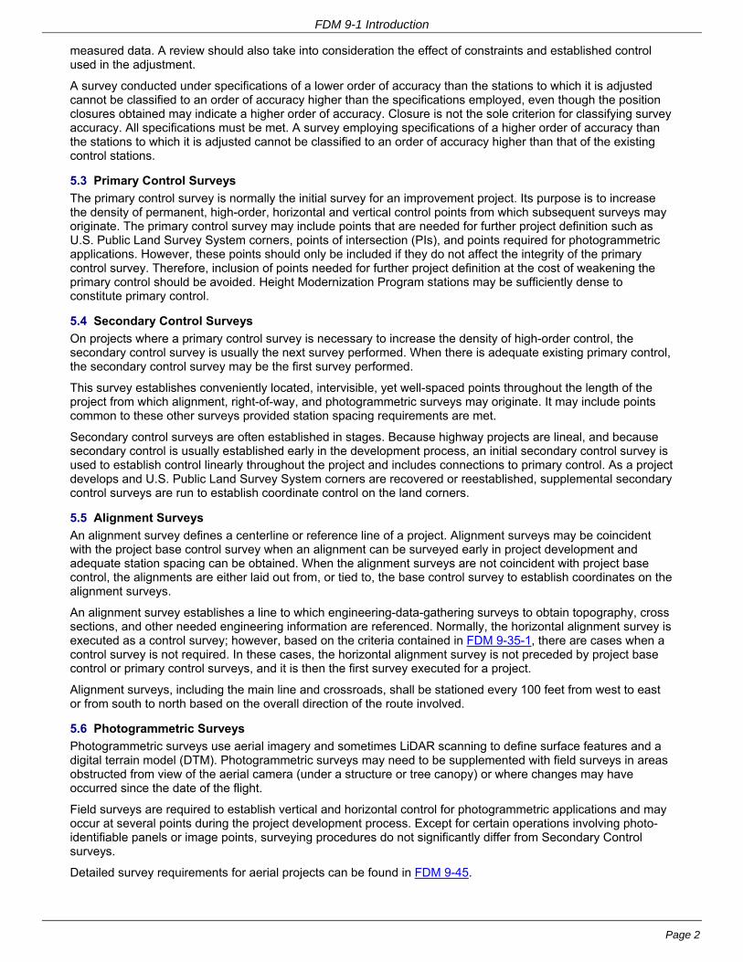
5.6 Photogrammetric Surveys
Photogrammetric surveys use aerial imagery and sometimes LiDAR scanning to define surface features and a digital terrain model (DTM). Photogrammetric surveys may need to be supplemented with field surveys in areas obstructed from view of the aerial camera (under a structure or tree canopy) or where changes may have occurred since the date of the flight.
Field surveys are required to establish vertical and horizontal control for photogrammetric applications and may occur at several points during the project development process. Except for certain operations involving photo-identifiable panels or image points, surveying procedures do not significantly differ from Secondary Control surveys.
Detailed survey requirements for aerial projects can be found in FDM 9-45.

FDM 9-1 Introduction
Page 3
5.7 Right-of-Way Surveys
A right-of-way survey marks the right-of-way boundaries and establishes the right-of-way reference line, if necessary. The right-of-way reference line will normally be the same line as the project reference line. Right-of-way surveys may also include surveys to gather information on property lines, lines of occupation, and land improvements.
FDM 9-1-10 Automation Links to Surveys December 21, 2010
New technologies and methods are changing the way information is collected, stored, processed, used, and passed between parties. These changes are constantly evolving. For up-to-date information contact the originator of this chapter.
FDM 9-1-15 Need for Accuracy December 21, 2010
The quality of the information in a survey database is important to its users. It should never be necessary to think of a centerline station distance as being plus or minus 1 foot. It is not acceptable to establish and to measure a project centerline using a cloth tape, or to run a level circuit using a wooden folding rule and a hand level. While these are extreme examples, they demonstrate that standards and procedures are necessary and that the economic use of standards and procedures requires the methods selected for use be designed to attain the desired results. Therefore, standards and procedures should be thought of as a means of applying quality control to the information in a survey database.
For an explanation of precision and accuracy, consult a surveying textbook (e.g., Elementary Surveying: An Introduction to Geomatics, by Ghilani) or similar resource.

Page 1
Facilities Development Manual Wisconsin Department of Transportation
Chapter 9 Surveying and Mapping Section 5 Policies
FDM 9-5-1 Preservation of Survey Monuments August 15, 2019
1.1 General It is the policy and practice of WisDOT to take all reasonable measures to perpetuate, preserve and replace survey monuments. Therefore, all reasonable efforts will be taken to assure that no survey monuments will be destroyed, disturbed, removed or buried to the degree that they are no longer usable without first following the instructions listed below.
United States Public Land Survey System (USPLSS) corners, Boundary Monuments and Geodetic Survey Control Stations are the most significant types of monuments found within road rights of way. USPLSS corners and boundary monuments are used to help identify land ownership boundaries while geodetic survey control station monuments mark a location where a precise elevation and/or latitude and longitude have been determined. They are two completely separate entities. If USPLSS or boundary monuments are disturbed or destroyed, they can be replaced in substantially the same location using local references. Geodetic stations, if disturbed or destroyed, must be replaced and resurveyed in their entirety due to their precision.
Refer to CMM 7-85 for additional information.
1.2 Definitions Accessory: A nearby physical object to which corners or monuments are referenced for perpetuation or recovery. Distances and/or directions are measured from the corner or monument to the accessory. Examples may include trees, poles, roads, fences or any other easily discernible object. Accessories should be selected based on location and permanence and can be natural or man-made.
Boundary Line: A line of demarcation between adjoining lands. Boundary lines may delineate areas of different political jurisdiction and/or different land parcels. Land parcel boundaries are more commonly referred to as ‘property lines’ and may have the same ownership on both sides of the line.
Boundary Monument: Physical object(s) placed on or near a boundary line to preserve and delineate a line where two land areas meet. Boundary Monuments may delineate lines of political and/or land parcel boundaries. Also see Boundary Line.
Corner: A point on the Earth where two or more land boundary lines meet denoting the end or a change of direction in the line. This is not the same as Monument, which is a physical object used to represent the location of a corner. The terms Monument, Mark, Landmark, Corner, Point and Station are not synonymous, but are often used interchangeably.
Geodetic Survey Control Station: A survey monument with either a precise latitude and longitude used for horizontal control, or a precise elevation used for vertical control, or both that has been determined by the most rigorous of surveying methods to meet the specifications set forth by the National Geodetic Survey (NGS). A typical Geodetic Survey Control Station established by WisDOT’s Height Modernization Program is a 3.5” bronze disk set in a 16” diameter concrete post, with the survey monument’s position of record published as part of NGS’ National Spatial Reference System (NSRS).
Landmark: See monument.
Lost USPLSS Corner or Monument: From the 2009 BLM Manual of Surveying Instructions, a lost corner or monument is one whose original position cannot be determined by substantial evidence, either from traces of the original marks or from acceptable evidence or reliable testimony that bears upon the original position. The location of a lost corner can be restored only by proportioning to one or more existing interdependent corners.
Monument: A physical object that indicates the location of a corner or a point determined by survey. Monuments may include (but are not limited to) a brass disk in concrete, iron rods or pipes with or without plastic caps, chiseled X’s, PK nails etc. More than one monument may define a location. The terms Monument, Mark, Landmark, Corner, Point and Station are not synonymous, but are often used interchangeably.
Obliterated USPLSS Corner or Monument: From the 2009 BLM Manual of Surveying Instructions, an obliterated corner is an existent corner where there are no remaining traces of the monument or its accessories but whose position may be recovered by substantial evidence from the reliable testimony of competent witnesses, or by acceptable record evidence.

FDM 9-5 Policies
Page 2
Parcel (Land): A continuous area or acreage of land which is described with its own unique land description such as metes and bounds, etc. Adjoining land parcels can have the same or different owners.
Perpetuate: The establishment of monuments, accessories and other relevant evidence that sustains the location of a corner in the event of its destruction. Corners can be perpetuated, geodetic survey control stations cannot. Perpetuations of corners should be recorded with the appropriate jurisdiction to preserve the chain of evidence from the present day back to the original monument. Geodetic survey control stations have measurements to other monuments and/or accessories to help locate the station but are not used to perpetuate it.
Property Corner: The same as a land parcel corner. A property corner may or may not have a monument designating its location.
Replace/Reset/Restore: The reestablishment of a survey monument that has been destroyed or disturbed in the same location as the original monument. The original location is typically determined via perpetuation of the original monument prior to destruction. Land Parcel monuments and Section Corners can be reset, but Geodetic Survey Control Stations cannot. The terms Replace, Reset and Restore are often used interchangeably.
United States Public Land Survey System (USPLSS): System of surveys that began in 1784 by the US Federal Government that provides direction and instruction for the orderly survey and subdivision of federally owned lands into grids prior to settlement. The grids from largest to smallest are: Townships (also called Congressional Townships to distinguish from Political Townships), Sections, Quarter Sections, Quarter-Quarter Sections (40 acres) and so on. Generally, the original USPLSS surveys monumented township and section exteriors. Further subdivisions and Monumentation was carried out by local surveyors. In Wisconsin, the USPLSS surveys began in December 1831 with substantial completion in 1866. Further information can be found in FDM 9-20-5 or most introductory survey textbooks.
Wisconsin Height Modernization Program (HMP): The Wisconsin Department of Transportation’s Division of Transportation Systems Development, Bureau of Technical Services, Geodetic Surveys Unit (GSU) is responsible for the development and maintenance of the statewide vertical, horizontal, and gravitational geodetic control network in support of the Wisconsin Spatial Reference System (WSRS).
In 1998 the Wisconsin Department of Transportation’s Geodetic Surveys Unit, in conjunction with the National Geodetic Survey (NGS), began work on a Height Modernization Program in Wisconsin. The goal was to construct a dense statewide network of permanent Geodetic Survey Control stations with highly accurate, reliable heights using global positioning satellite technology with traditional leveling, gravity, and modern remote sensing methods.
Upon completion of initial Height Modernization Program efforts, the Geodetic Surveys Unit serves as chief custodian of the statewide Geodetic Survey Control Network, which includes the core functions of replacement and reestablishment of Geodetic Survey Control Stations that are disturbed and/or destroyed.
See CMM 7-85-2 for additional information.
1.3 Types of Monuments Typically Found along WisDOT Projects There are four categories of monuments typically found along WisDOT projects.
1. Geodetic Survey Control Station Monuments – cannot be perpetuated. If disturbed due to nearbyactivity it must be replaced. Contact the Geodetic Surveys Unit by phone 866-568-2852 or [email protected] if a project may endanger a geodetic survey control station. See FDM 9-5-1.4 formore details.
2. United States Public Land Survey System (USPLSS) Monument - shall be perpetuated prior toconstruction. See FDM 9-5-1.5 for more details.
3. Land Parcel or Boundary Monument - shall be perpetuated prior to construction. See FDM 9-5-1.5for more details.
4. Any other types of monuments - contact the appropriate WisDOT region survey coordinator forguidance prior to disturbing.
1.4 Geodetic Survey Control Station Replacement Procedure When a Wisconsin Height Modernization Program geodetic survey control station will be disturbed or destroyed during construction, it must be replaced and reestablished as specified in the "Geodetic Survey Control Station Replacement Procedure". The "Geodetic Survey Control Station Replacement Procedure" was created to describe the roles, responsibilities, and funding necessary to ensure the replacement and reestablishment of a HMP geodetic survey control station is performed to the same specification and survey accuracy of the station it

FDM 9-5 Policies
Page 3
is replacing.
The Geodetic Survey Control Station Replacement Procedure can be found here:
https://wisconsindot.gov/Documents/doing-bus/eng-consultants/cnslt-rsrces/tools/wiscors/geodetic-control-replacement-procedure.pdf
1.5 Procedure to Perpetuate USPLSS and/or Land Parcel Boundary Monuments 1. Each region will notify all counties, villages and cities of upcoming construction projects within their
county/municipal boundaries that may endanger or disturb any survey monument. This notification willbe sent out at least 60 days before the start of construction. This notification will include the locationand limits of the project as well as the anticipated start of construction. This notification will serve as the30-day written notice as required by Wis. Stat. s. 59.74(2)(b)1, that a survey monument may bedestroyed.
2. A thorough search of the records will be made to determine if monuments of public record exist on theproposed project. County surveyors and city/village engineers will be asked to research their recordsand provide WisDOT with any information they have concerning survey monuments within the projectlimits.WisDOT will make a thorough search of the records in the region office.
3. WisDOT will make a determination of which monuments may be endangered and notify the county,village or city of these monuments.
4. At least 30 days before construction, the county surveyor and city/village engineer will be asked toinform the region of the monuments that will be preserved by the county surveyor and city/villageengineer under statute s. 59.74(2)(b)1.
5. The WisDOT region survey unit will determine if there are recorded monuments in addition to thoseperpetuated by the county or municipality that are deemed necessary to preserve in the public interest.These additional recorded monuments shall be perpetuated per the instructions of the region surveycoordinator.
6. WisDOT will make a field survey of the affected monuments and witness monuments and provide acopy to the county. This will be done for informational purposes only. A note will state explicitly that thismonument is not being certified as an actual corner, only that a certain type of monument was foundand is perpetuated by a monument or reference monuments. This will be done at WisDOT cost.
7. Upon completion of construction, WisDOT will, if requested, reset an appropriate type of monument inthe original location. WisDOT will file with the county/municipality the type of monument set. This will bedone for informational purposes only. The notes will state that this monument is not being certified asan actual monument, only that certain evidence of a monument was found and that due to construction,it was necessary to remove and reset a monument at the location. This service will be provided byWisDOT at its expense. Resetting of monuments shall be done under the responsible charge of aProfessional Land Surveyor (PLS) per Wisconsin Statute 443.01(6s)(c). A Monument PerpetuationDocument is required for this procedure (See FDM 9-5-3).
8. If WisDOT has determined that a lost or obliterated United States Public Land Survey System(USPLSS) monument must be restored, the first point of contact will be the county surveyor (ordesignated representative if there is no county surveyor) where the monument in question is located.Per State Statute 59.74(2)(d), the cost of perpetuating the evidence of any [USPLSS] monument shallbe borne by the county or counties where the monument is located.
9a. In the areas that are acquired as new fee acquisition, WisDOT shall notify the owner that it will facilitate, upon request, the actual and reasonable cost to have new property monuments set on the new right-of-way line in those instances where there is an existing property survey by a Professional Land Surveyor (PLS) and evidence of monumentation is found or identified prior to construction for the property in question. By facilitate, the region has the option to pay the property owner to hire a PLS or hire a PLS directly to set monuments on the new right-of-way line. Property owner notification to WisDOT for setting of property monuments on the new right-of-way via the above procedure shall occur prior to the closing of the construction project. The region Technical Services Chief or designee in consultation with the Project Development, Real Estate, Survey, Plat and other relevant region unit(s) shall determine if WisDOT will pay for new property monuments in areas new right-of-way acquisition area that does not meet the above qualifications.
9b. In the areas where rights and or other interests (e.g. Temporary Limited Easement (TLE), Permanent Limited Easement (PLE), Highway Easement (HE), etc.) are being acquired by WisDOT, WisDOT will

FDM 9-5 Policies
Page 4
replace any property monuments that are damaged or destroyed as a result of construction activities provided that there is an existing property survey by a Professional Land Surveyor (PLS) and evidence of monumentation is found or identified prior to construction for the property in question. Property owner notification to WisDOT for replacement property monuments shall occur prior to the closing of the construction project. The region Technical Services Chief or designee in consultation with the Project Development, Real Estate, Survey, Plat and other relevant region unit(s) shall determine if WisDOT will pay for monument replacement of a property in area(s) where rights or other interests are acquired but does not meet the property survey or monumentation qualifications mentioned above. A Monument Perpetuation Document is required for this procedure (See FDM 9-5-3).
10. In areas where there are no Real Estate acquisitions, the construction contractor will be responsiblefor having a Professional Land Surveyor (PLS) replace any property monument that is damaged or destroyed during construction. Per the requirements in areas of new right-of-way acquisition, the property owner must be able to provide an existing property survey by a Professional Land Surveyor (PLS) and evidence of monumentation prior to construction. The property owner shall notify WisDOT or WisDOT’s representative of any missing property monuments prior to the closing of the construction project. A Monument Perpetuation Document is required for this procedure (See FDM 9-5-3).
FDM 9-5-3 Monument Perpetuation Document August 15, 2019
A Wisconsin Department of Transportation Monument Perpetuation Document (MPD) is a document that verifies monuments found prior to a transportation improvement construction project, but subsequently disturbed by construction activities, were replaced in the same location. It will also state the type of monument that was reset, providing future users evidence as to why a monument type representing a location may have changed. Typically, monuments referenced for this procedure will include disturbed monuments that are within Temporary Limited Easement (TLE) areas, within Permanent Limited Easement (PLE) areas or accidentally disturbed by construction activities. Per FDM 9-5-1.5 7,9b and 10, the monument to be replaced must be found and identified prior to construction for it to be replaced.
A Monument Perpetuation Document is NOT to be used for monuments that are disturbed because of new fee acquisition by WisDOT. See FDM 9-5-1.5 9a for procedures to have new property monuments set on a new right-of-way line.
A Monument Perpetuation Document states that the replaced monuments are to be used as evidence of existing monumentation prior to construction without opinion as to their validity as a property corner. An MPD may not be a true representation of existing property lines, should not be used as a substitute for an accurate field survey, does not depict a property survey and does not comply with Wisconsin Administrative Rule AE-7.
Resetting of monuments and creation of a Monumentation Document shall be done under the responsible charge of a Professional Land Surveyor (PLS) per Wisconsin Statute 443.01(6s)(c).
3.1 Monument Perpetuation Document Procedure When construction is completed, the project construction oversight firm will then hire a surveyor or survey firm to replace disturbed monuments and create the Monument Perpetuation Document.
Contact the WisDOT Region Survey Coordinator to determine if the Region would like to review the MPD prior to general distribution.
The preparer will send the approved MPD to the WisDOT Region Survey Coordinator for distribution and filing within WisDOT and the appropriate County Surveyor (or the designated representative) for distribution within the county.
Please see the following link for current county surveyor (or designee) name, phone number and email address. https://www.sco.wisc.edu/county-surveyors/
3.2 Monument Perpetuation Document Examples The following Monument Perpetuation Documents are shown as possible examples of how a MPD can be formatted. It is not required that the final MPD resemble any of the examples, they are provided as guide. Final determination as to whether a submitted MPD is acceptable shall be made by the Region Survey Coordinator. 3.2.1 Edit an Existing Transportation Project Plat If a WisDOT transportation improvement project requires the acquisition of permanent land interests, then it is required that a Transportation Project Plat (TPP) be completed for the project per FDM 12-10.

FDM 9-5 Policies
Page 5
An efficient and cost-effective way to create a Monument Perpetuation Document is to edit an existing Transportation Project Plat (TPP) with the following edits, note that the numbered items below correspond to the numbered items on Attachment 3.1.
1. Replace the Relocation Order with WISCONSIN DEPARTMENT OF TRANSPORTATION MONUMENT PERPETUATION DOCUMENT
2. Remove the recording information block in the upper right-hand corner of the TPP.
3. Insert the following statement in the recording information block This document may not be a true representation of existing property lines and should not be used as a substitute for an accurate field survey.
4. Insert the following statement in the recording information block This Monument Perpetuation Document does not depict a property survey and does not comply with Wisconsin Administrative Rule AE-7.
5. Clear the entire signature block of the text, signatures and surveyor stamp.
6. Insert the following statement in the old signature block: I, <Name of Surveyor>, Professional Land Surveyor, certify that I have perpetuated the monuments shown on this document based on information provided to me by the Wisconsin Department of Transportation. The replaced monuments are to be used as evidence of existing monumentation prior to construction without opinion as to their validity as a property corner.
7. Surveyor signs and stamps the document.
8. Callout boxes and arrows pointing to the monument location and listing the following required information for monuments replaced via this example:
Found: type of monument found prior to constructionSet: type of monument set after construction
Coordinates of the monument in X and Y (not Northing and Easting) in the same coordinate system as the project. Coordinate precision for all perpetuated monuments shall be at least 0.01 feet (two decimals) with a maximum precision of 0.001 feet (three decimals). Every monument coordinate on a document shall have the same precision (number of digits after the decimal).
A table may be used in lieu of call-out boxes and arrows (see item 9).
9. A table can be placed on the appropriate TPP page in lieu of callouts and arrows. The table must be given a distinctive table name and every monument must be given a distinctive name or ID number.
10. Any other information that would be pertinent to this project.
11. It is recommended, but not required, to use red font for call-outs or tables for the MPD to better distinguish information added after the filing of the TPP.
3.2.2 Table Options For projects that have very few disturbed monuments, a Monument Perpetuation Document may be submitted as a standalone table or a table with appropriate maps, county GIS screen captures or TLE Exhibit (FDM 12-20) screen captures with perpetuated monuments identified with unique point labels.
Requirements for Table Option (note that the lettered items below correspond to the lettered items on Attachments 3.2 and 3.3.
A. Point labels on additional maps submitted as part of the Monument Perpetuation Document can be used in the Location column in lieu of a complete description. The Quarter-Quarter Section (or equivalent), Section Town, Range and Municipality must be listed in a column. It is advisable, but not required, to give additional brief information regarding the monument location in the Location column.
B. Horizontal datum with adjustment year and coordinate system of the document. They shall be identical as the datum and coordinate system of the project.
C. Surveyors certificate which includes the following text: I, <Name of Surveyor>, Professional Land Surveyor, certify that I have perpetuated the monuments shown on this document based on information provided to me by the Wisconsin Department of Transportation. The replaced monuments are to be used as evidence of existing monumentation prior to construction without opinion as to their validity as a property corner.

FDM 9-5 Policies
Page 6
D. The following two statements:
1) The information on this document may not be a true representation of existing property corners and should not be used as a substitute for an accurate field survey.
2) The information on this document does not depict a property survey and does not comply with Wisconsin Administrative Rule AE-7.
E. WisDOT project information- This must include the WisDOT Project ID and may include any additional relevant project information (i.e. TLE Exhibit number, structure number etc.).
F. Table Columns shall show the following required information for monuments replaced via this example:
1) Found: type of monument found prior to construction
2) Set: type of monument set after construction
3) Coordinates of the monument in X and Y (not Northing and Easting) in the same coordinate system as the original Transportation Project Plat. Coordinate precision for all perpetuated monuments shall be at least 0.01 feet (two decimals) with a maximum precision of 0.001 feet (three decimals). Every monument coordinate on a document shall have the same precision (number of digits after the decimal).
G. The PLS will sign and stamp the document page that has the Surveyors Certificate described in item C above.
H. PAGE X of Y shall be on the bottom of all pages submitted as part of the table option:
Table Option with Maps The table, certificate and note items (items A through G above) will appear on the first page(s) of the Monument Perpetuation Document followed by the maps on later pages (Attachment 3.2). It is recommended that every map be labeled with its Section, Township, Range and Town or Municipality to help determine the map location. Every monument listed in the table must have a table column listing the monument the Quarter-Quarter Section (or equivalent), Section, Township, Range, Township or Municipality name.
Table Option without Maps- If a Monument Perpetuation Document table is created without additional maps, it is important that the location descriptions must be detailed enough so that there is no doubt about what monument is being discussed (Attachment 3.3). In addition to detailed location description, every monument listed in the table must state the Quarter-Quarter Section (or equivalent), Section, Township, Range, Township or Municipality name.
3.3 Notes about Coordinates on Monument Perpetuation Documents The inclusion of coordinates for a Monument Perpetuation Document is intended to help guide users to locate the monument in question. The coordinates are not intended and should never be used to subsequently reset a monument once it has been reset after the construction project that created the MPD.
It is not a requirement that all perpetuated monuments have coordinates listed. Monuments can be reset in the same location from reference ties or other evidence without obtaining coordinates. It should be noted in the coordinate column or call out box that ‘no coordinates obtained’ or ‘NA’ so that future users do not think that the lack of coordinates is an oversight. Briefly state why coordinates for a monument are not listed in the table. A typical example is ‘Reset From Ties’.
LIST OF ATTACHMENTS Attachment 3.1
Attachment 3.2
Attachment 3.3
Edited Transportation Project Plat Example
Table Option with Maps Example
Table Option without Maps Example
FDM 9-5-5 Right-of-Way Monumentation December 21, 2010
Right-of-way monuments shall be set for all transportation projects requiring right-of-way acquisition.
Refer to Attachment 5.1 for the department’s policy on right-of-way monumentation, to FDM 9-25-6 for right-of-way monumentation, implementation methods and requirements, and to FDM 9-5-10 for the department’s policy on standard geodetic references.
Requests for information about this procedure should be directed to the Right-of-Way Plat Coordinator/Land Surveyor at 608-243-3397 or the Chief Surveying & Mapping Engineer at 608-246-7941.

FDM 9-5 Policies
Page 7
LIST OF ATTACHMENTS Attachment 5.1 Right-of-Way Monumentation Policy
FDM 9-5-10 Standard Geodetic References March 28, 2014
The Department policy on geodetic datums and coordinates specifies having a single standard reference for horizontal measurements, a single standard reference for vertical measurements, and a single standard for large-scale mapping. This policy became effective January 1, 1997 and is applicable to all new work begun after that date. The standard geodetic references as revised in January 2014 are as follows:
Horizontal Datum (HMP1 area) North American Datum of 1983 adjustment of 2011 NAD 83 (2011)
Horizontal Datum (non-HMP area) North American Datum of 1983 adjustment of 1991 NAD 83 (1991)
Vertical Datum (HMP area) North American Vertical Datum of 1988 adjustment of 2012 NAVD 88 (2012)
Vertical Datum (non-HMP area) North American Vertical Datum of 1988 adjustment of 1991 NAVD 88 (1991)
Rectangular Coordinate System (except in Jackson County)
Wisconsin County Coordinate System (WCCS) or Wisconsin Coordinate Reference Systems (WISCRS)
Rectangular Coordinate System in Jackson County
WISCRS, which is the same as the Jackson County Official Coordinate System (JCOCS)
The standard reference shall be used for all data collection, maintenance, integration, analysis, reporting activities, and large-scale conformal mapping. This includes all survey work, photogrammetric mapping, and project development activities for which the department provides funding. Using a standard reference will eliminate the additional effort, costs, and errors associated with using various references.
To reduce the confusion over the references used for a project, WisDOT staff are encouraged to complete Form DT1773, Geodetic References Documentation, for every project and file the completed form with the project. If a non-standard geodetic reference is used, the region survey coordinator should fill out Form DT1773 to document the circumstances regarding the decision to use a non-standard datum. There is no requirement to complete either of the above. The form is available online from the Authorized Forms list. The references normally should be selected at the time the scoping meeting Survey Worksheet is completed, but no later than shortly after the scoping meeting and in accordance with Minimum Data Requirements (see FDM 9-43-1).
The region survey coordinators are responsible for overseeing the region’s survey projects; therefore, their choice of which datum and coordinate system to use should be followed. Generally, they are the ones that are most knowledgeable regarding what old projects, control, etc, exist in the area of a project and are best suited to decide the benefits/detriments of which datum and coordinate system should be used for any new project. If the region survey coordinators have questions or concerns, they should contact the Central Office Geodetic Surveys Unit for assistance.
Be sure to check three boxes on Form DT1773: - One box for the standard horizontal reference.- One box for the standard vertical reference.- One box for the standard coordinate reference.
Below are some factors to consider when deciding on a project datum and coordinate system: - The type of project: See FDM 3-5-2 for definitions and examples of project types. Also, see FDM 9-43-
1 for survey activities associated with each of these types of projects.- Alternative references available in the project area.- Whether right-of-way acquisition will, or will not, be required for the project.- References used for nearby projects.- Any extenuating circumstances.- Approximate effort (cost and/or crew time) to provide the requested reference and approximate effort
to provide another reference for the project.
1 Height Modernization Program. Contact the Chief, Surveying and Mapping Section for information on where the HMP has been completed.

FDM 9-5 Policies
Page 8
- The delay caused to the project if one reference is used over another.
Whether a standard reference or a nonstandard reference is used for a project, the coordinate values and datum of existing control used as starting point(s) to establish engineering (project) control shall be shown in the metadata of all project documents listing engineering control. This will assist future users of the project data in learning the origin of the engineering control.
For more information, see the procedures and their subject matter listed as follows:
FDM 9-20-15 Horizontal Datums
FDM 9-20-20 Vertical Datums
FDM 9-20-25 Coordinate Systems
FDM 9-20-26 Wisconsin State Plane Coordinate System
FDM 9-20-27 Wisconsin County Coordinate System
FDM 9-20-28 Wisconsin Coordinate Reference Systems
FDM 9-43-1 Minimum Data Requirements
FDM 9-5-15 Requests for Photogrammetric Products and Services December 21, 2010
It is the policy of WisDOT that all requests for products and services produced through photogrammetric methods (aerial imagery) and related sensor technologies (LiDAR scanning) shall be coordinated through the Photogrammetry Unit.
15.1 Procedure Each region has a point of contact for requests, typically the Survey Unit Coordinator. Requests from other bureaus and any questions should be emailed to [email protected].
When a consultant has a contract with WisDOT, the bureau or region responsible for the contract shall coordinate with the Photogrammetry Unit. Consultants should not make requests directly to the Photogrammetry Unit.
The Photogrammetry Unit shall be informed early in negotiations with design consultants when there is a possibility that photogrammetric methods will be needed. The Photogrammetry Unit will attempt to provide the needed data. When workload exceeds in-house resources, the Photogrammetry Unit will prepare, negotiate and administer photogrammetric consultant contracts. The Photogrammetry Unit will provide deliverables to the requestor for transmittal to the consultant. All costs will be charged to the project ID.
In some cases, the Photogrammetry Unit may determine the work can be performed through the prime design contract or by subcontract. In the latter case, the Photogrammetry Unit will assist the requestor with standards and specifications and will provide review of the deliverables.
15.2 Resources A list of products and services are specified in the online catalog.

44
STH 23 (WASHINGTON ST)
DARLINGTON
ST
H 2
3
WASHINGTON
ST
W H
AR
RIE
T S
T
W M
AR
Y S
T
W M
AR
Y S
T
W L
UC
Y S
T
Δ.
CITY
OF
BLOCK 55
ORIGINAL PLAT OF
THE CITY OF DARLINGTON
BLOCK 54
OR
IG
IN
AL
P
LA
T O
F T
HE
CIT
Y O
F D
AR
LIN
GT
ON
BL
OC
K 4
BL
OC
K 3
ORIGINAL PLAT OF THE CITY OF DARLINGTON
BLOCK 52
ORIGINAL PLAT OF THE CITY OF DARLINGTON
Δ
Δ
Δ
BLOCK 53
ORIGINAL PLAT OF THE CITY OF DARLINGTON
I, Michael J. Heberlein, Professional Land Surveyor, certify that I have perpetuated the monuments shown on this document based on information provided to me by the Wisconsin Department of Transportation. The replaced monuments are to be used as evidence of existing monumentation prior to construction without opinion as to their validity as a property corner.
Found 1" Iron PipeSet: 3/4" Iron PipeY: 123390.77X: 987654.32 Found: PK Nail
Set: Chiseled 'X' Y:123756.89 X: 987654.32
Wisconsin Department of Transportation Monument Perpetuation Document
Found 3/4" RebarSet: Chiseled X in Conc.Y: 123456.79X: 987720.32
Found: 1/2" Rebar Set: Chiseled X in Conc. Y: 555222.21 X: 888111.43
Found 1" Iron Pipe Set: Chiseled X in Conc. Y: 777888.53 X: 777666.99
This document may not be a truerepresentation of existing propertylines, and should not be used as asubstitute for an accurate fieldsurvey.
This Monument PerpetuationDocument does not depict aproperty survey and does notcomply with WisconsinAdministrative Rule AE-7.
2101
21042103
2102
Monument Perpetuation Table
T1106
11001
2
4
3
5
6
7
88
8
8
8
9
Michael J. H
eberlein
Not to Scale
Note: White numbers with
a circle around itcorrespond with the
same numbereditem in FDM
9-5-3.2.1
FDM 9-5 Attachment 3.1 Edited Transportation Project Plat Example
August 15, 2019 Attachment 3.1 Page 1

FDM 9-5 Attachment 3.2 Table Option with Maps Example
August 15, 2019 Attachment 3.2 Page 1
Note White letters with a circle around it
correspond to the same lettered item in FDM 9-5-3.2.2
June 29, 2019
I, <Name of Surveyor>, Professional Land Surveyor, certify that I have perpetuated the monuments shown on this document based on information provided to me by the Wisconsin Department of Transportation. The replaced monuments are to be used as evidence of existing monumentation prior to construction without opinion as to their validity as a property corner.
The information on this document may not be a true representation of existing property corners and should not be used as a substitute for an accurate field survey.
The information on this document does not depict a property survey and does not comply with Wisconsin Administrative Rule AE-7. A
WisDOT Ref: 1234-43-0629 USH 351 (Old 10 Rd-Galena St) Eagle County WI F3 F3
A Location
Quarter-Quarter Section, Section, Town, Range and
Municipality
F1
Found
F2
Set X Coordinate Y Coordinate
Point 1306
Near the NE Corner Eagle County VFW Post
NW1/4, SE1/4, S24, T66N, R2E, City of Carlson, Eagle County, WI
3/4” rebar
Chiseled X in concrete 777322.43 342348.43
Point 1309
Near the South Corner Eagle County VFW Post
SW1/4, SE1/4, S24, T66N, R2E, City of Carlson, Eagle County, WI
3/4” rebar
3/4” rebar with Red DOT Cap
777371.98 342150.89
Point 1351 Near the Southwest corner of property at 1234 USH 351, Carlson, WI
SW1/4, SW1/4, S9, T66N, R2E, Town of Bruin, Eagle County, WI
3/4” rebar
3/4” rebar with red DOT cap
Reset using county ref tie for SW corner S17, T66N, R2E
NA
Point 1591 Near SE corner Lot 1 CSM 1492, S10, T65N, R2E, Eagle County, WI
NW1/4, SE1/4, S10, T65N, R2E, Town of Maple, Eagle County, WI
1/2“ rebar with yellow cap
3/4” rebar with Red DOT Cap
766760.63 321225.60
Coordinates for the above table are Wisconsin Coordinate Reference System (WISCRS) Eagle County NAD 83(2011).
Michael J. Heberlein Michael J. Heberlein Consultant Surveys, llc 1234 Main St. Anycity, WI 99999
C
D1
D2
E
B
G
G
1234-43-0629 USH 351 (Old 10 Rd-Galena St) Eagle County WI

FDM 9-5 Attachment 3.2 Table Option with Maps Example
August 15, 2019 Attachment 3.2 Page 2
S24, T66N, R2E, City of Carlson, Eagle County, WI
A
A
1234-43-0629 USH 351 (Old 10 Rd-Galena St) Eagle County WI

H
FDM 9-5 Attachment 3.2 Table Option with Maps Example
August 15, 2019 Attachment 3.2 Page 3
S.8, 9, 16 and 17, T66N, R2E, Town of Bruin, Eagle County, WI
A
1234-43-0629 USH 351 (Old 10 Rd-Galena St) Eagle County WI

H
FDM 9-5 Attachment 3.2 Table Option with Maps Example
August 15, 2019 Attachment 3.2 Page 4
S10, T65N, R2E, Town of Maple, Eagle County, WI
A
1234-43-0629 USH 351 (Old 10 Rd-Galena St) Eagle County WI

H
FDM 9-5 Attachment 3.3 Table Option with Maps Example
August 15, 2019 Attachment 3.3 Page 1
G
Note White letters with a circle around it
correspond to the same lettered item in FDM 9-5-3.2.2
A
April 29, 2019
I, <Name of Surveyor>, Professional Land Surveyor, certify that I have perpetuated the monuments shown on this document based on information provided to me by the Wisconsin Department of Transportation. The replaced monuments are to be used as evidence of existing monumentation prior to construction without opinion as to their validity as a property corner.
The information on this document may not be a true representation of existing property corners and should not be used as a substitute for an accurate field survey.
The information on this document does not depict a property survey and does not comply with Wisconsin Administrative Rule AE-7.
WisDOT Ref: 9990-87-45 Bridge B16-078
A Location
Quarter-Quarter Section, Section, Town, Range and
Municipality
Found Set X Coordinate Y Coordinate
Near the Northwest corner of Lot 3, Block 55 Original Plat of the City of Anytown, WI
NW1/4, NW1/4, S16, T17N, R15W, City of River City, River County, WI
½” rebar Chiseled X in concrete 555222.21 888111.43
Near the Northwest corner of Lot 6 River County CSM 4443 3567 STH QQ, Anytown, WI
Govt Lot 4, S16, T18N, R15W, Town of Hoke, River County, WI
¾” rebar ¾” rebar 556765.54 889100.87
Near the Northwest corner of Lot 6 River County CSM 4443 3567 STH QQ, Anytown, WI
Govt Lot 4, S16, T18N, R15W, Town of Hoke, River County, WI
¾” rebar ¾” rebar 556765.04 889100.37
Near SE corner NW1/4, SE1/4, S10, T18N, R15W, River County, WI
NW1/4, SE1/4, S10, T18N, R15W, Town of Hunter, River County, WI
Center of 4x4 wood post with railroad spike
1” rebar 550987.88 890654.77
Coordinates for the above table are Wisconsin Coordinate Reference System (WISCRS) River County NAD 83(2011).
Michael J. Heberlein G
Michael J. Heberlein Consultant Surveys, LLC 234 Main St. Anycity, WI 99999
C
D1
D2
E
B
F1 F2 F3 F3
H

FDM 9-5 Attachment 5.1 Right-of-Way Monumentation Policy
February 28, 2001 Attachment 5.1 Page 1
RIGHT-OF-WAY MONUMENTATION POLICY Right-of-way monuments shall be set to adequately define the right-of-way line, for all transportation projects requiring right-of-way acquisition. Type 2 monuments with an adjacent right-of-way marker post shall be placed at every change in direction of right-of-way line including the beginning and ending of curves. A Type 1 monument shall be used in lieu of a Type 2 monument where a more substantial monument is needed. The maximum spacing between right-of-way monuments shall be approximately 0.25 mile (0.40 km) on tangents and 500 feet (150 m) on curves. Right-of-way monuments shall be located using survey procedures that will ensure a minimum accuracy of one part in three thousand (1:3000) and be referenced to adjacent U.S. Public Land Survey System (PLSS) corners. Corners with established coordinates shall be so identified. Corners without established coordinates shall have coordinates determined for them. The coordinates of the corners shall be shown on the plat. Refer to the Facilities Development Manual for right-of-way implementation methods and requirements, the standard detail drawing for a right-of-way marker post, and exceptions to placing a marker post. When Type 1 monuments are used, the location of each Type 1 monument shall be provided to the county surveyor in addition to being identified on the right-of-way plat. The Type 1 monuments shall be located using survey procedures that will ensure a minimum accuracy of one part in ten thousand (1:10,000). Type 1 monuments shall be set by contract bid item unless stated on the plan and profile to be set by others. Each district shall develop and maintain suitable documentation showing the location of Type 1 and Type 2 monuments. Monumentation shall be established in a timely manner within the limits of the district workload. Minor right-of-way acquisitions shall be tied to a PLSS corner, have a basis of bearing, meet minimum accuracy of one part in three thousand (1:3000), and be monumented with Type 2 monuments. To meet the requirement for a basis of bearing, the acquisition must either be controlled by coordinates or be tied to two monumented PLSS corners. This Policy supersedes the Wisconsin Department of Transportation Right-of-Way Monumentation Policy dated September 1, 1999, and all other previous right-of-way monumentation policies.

44
STH 23 (WASHINGTON ST)
DARLINGTON
ST
H 2
3
WASHINGTON
ST
W H
AR
RIE
T S
T
W M
AR
Y S
T
W M
AR
Y S
T
W L
UC
Y S
T
Δ.
CITY
OF
BLOCK 55
ORIGINAL PLAT OF
THE CITY OF DARLINGTON
BLOCK 54
OR
IG
IN
AL
P
LA
T O
F T
HE
CIT
Y O
F D
AR
LIN
GT
ON
BL
OC
K 4
BL
OC
K 3
ORIGINAL PLAT OF THE CITY OF DARLINGTON
BLOCK 52
ORIGINAL PLAT OF THE CITY OF DARLINGTON
Δ
Δ
Δ
BLOCK 53
ORIGINAL PLAT OF THE CITY OF DARLINGTON
I, Michael J. Heberlein, Professional Land Surveyor, certify that I have perpetuated the monuments shown on this document based on information provided to me by the Wisconsin Department of Transportation. The replaced monuments are to be used as evidence of existing monumentation prior to construction without opinion as to their validity as a property corner.
Found 1" Iron PipeSet: 3/4" Iron PipeY: 123390.77X: 987654.32 Found: PK Nail
Set: Chiseled 'X' Y:123756.89 X: 987654.32
Wisconsin Department of Transportation Monument Perpetuation Document
Found 3/4" RebarSet: Chiseled X in Conc.Y: 123456.79X: 987720.32
Found: 1/2" Rebar Set: Chiseled X in Conc. Y: 555222.21 X: 888111.43
Found 1" Iron Pipe Set: Chiseled X in Conc. Y: 777888.53 X: 777666.99
This document may not be a truerepresentation of existing propertylines, and should not be used as asubstitute for an accurate fieldsurvey.
This Monument PerpetuationDocument does not depict aproperty survey and does notcomply with WisconsinAdministrative Rule AE-7.
2101
21042103
2102
Monument Perpetuation Table
T1106
11001
2
4
3
5
6
7
88
8
8
8
9
Michael J. H
eberlein
Not to Scale
Note: White numbers with
a circle around itcorrespond with the
same numbereditem in FDM
9-5-3.2.1
FDM 9-5 Attachment 3.1 Edited Transportation Project Plat Example
August 15, 2019 Attachment 3.1 Page 1
Page 1
Facilities Development Manual Wisconsin Department of Transportation Chapter 9 Surveying and Mapping Section 10 Public Relations
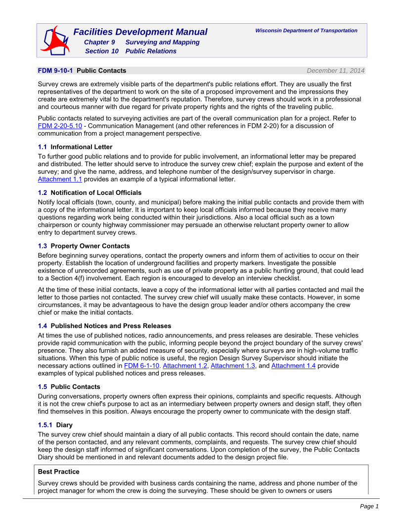
FDM 9-10-1 Public Contacts December 11, 2014
Survey crews are extremely visible parts of the department's public relations effort. They are usually the first representatives of the department to work on the site of a proposed improvement and the impressions they create are extremely vital to the department's reputation. Therefore, survey crews should work in a professional and courteous manner with due regard for private property rights and the rights of the traveling public.
Public contacts related to surveying activities are part of the overall communication plan for a project. Refer to FDM 2-20-5.10 - Communication Management (and other references in FDM 2-20) for a discussion of communication from a project management perspective.
1.1 Informational Letter
To further good public relations and to provide for public involvement, an informational letter may be prepared and distributed. The letter should serve to introduce the survey crew chief; explain the purpose and extent of the survey; and give the name, address, and telephone number of the design/survey supervisor in charge. Attachment 1.1 provides an example of a typical informational letter.
1.2 Notification of Local Officials
Notify local officials (town, county, and municipal) before making the initial public contacts and provide them with a copy of the informational letter. It is important to keep local officials informed because they receive many questions regarding work being conducted within their jurisdictions. Also a local official such as a town chairperson or county highway commissioner may persuade an otherwise reluctant property owner to allow entry to department survey crews.
1.3 Property Owner Contacts
Before beginning survey operations, contact the property owners and inform them of activities to occur on their property. Establish the location of underground facilities and property markers. Investigate the possible existence of unrecorded agreements, such as use of private property as a public hunting ground, that could lead to a Section 4(f) involvement. Each region is encouraged to develop an interview checklist.
At the time of these initial contacts, leave a copy of the informational letter with all parties contacted and mail the letter to those parties not contacted. The survey crew chief will usually make these contacts. However, in some circumstances, it may be advantageous to have the design group leader and/or others accompany the crew chief or make the initial contacts.
1.4 Published Notices and Press Releases
At times the use of published notices, radio announcements, and press releases are desirable. These vehicles provide rapid communication with the public, informing people beyond the project boundary of the survey crews' presence. They also furnish an added measure of security, especially where surveys are in high-volume traffic situations. When this type of public notice is useful, the region Design Survey Supervisor should initiate the necessary actions outlined in FDM 6-1-10. Attachment 1.2, Attachment 1.3, and Attachment 1.4 provide examples of typical published notices and press releases.
1.5 Public Contacts
During conversations, property owners often express their opinions, complaints and specific requests. Although it is not the crew chief's purpose to act as an intermediary between property owners and design staff, they often find themselves in this position. Always encourage the property owner to communicate with the design staff.
1.5.1 Diary
The survey crew chief should maintain a diary of all public contacts. This record should contain the date, name of the person contacted, and any relevant comments, complaints, and requests. The survey crew chief should keep the design staff informed of significant conversations. Upon completion of the survey, the Public Contacts Diary should be mentioned in and relevant documents added to the design project file.
Best Practice
Survey crews should be provided with business cards containing the name, address and phone number of the project manager for whom the crew is doing the surveying. These should be given to owners or users

FDM 9-10 Public Relations
Page 2
encountered during surveying operations.
LIST OF ATTACHMENTS
Attachment 1.1 Example of a Typical Informational Letter
Attachment 1.2 News Release - Highway Engineering Survey to Begin
Attachment 1.3 News Release - WisDOT Survey Work to Begin on STH 1
Attachment 1.4 News Release - Right-of-Way Staking to Begin on STH 1
FDM 9-10-5 Entry and Operations on Private Land December 13, 2006
5.1 Entry on Private Land
Department policy for entry on private land is based on s. 84.01(10) stats. The department does not have to ask for permission, but shall notify the owner/occupant1 that entry will occur, when it will occur, and why it will occur. It may be necessary to contact more than one person (e.g., owner of the land, renter, occupant, caretaker, and neighbor) to adequately provide information of the proposed project to everyone concerned or affected by the project.
Department personnel, or the department's representative, should contact the owner/occupant before beginning surveying operations.1 If it becomes necessary to reenter private land after a prolonged absence, then the owner/occupant should be contacted again before reentering the private land.
Direct specific questions regarding entry to the section chief in the Surveying & Mapping Section. If the question requires legal advice, the section chief will contact the Office of General Counsel.
5.2 Right of Entry Process
Although the statutes allow the right of entry on private land, the exercise of this right may require a Special Inspection Warrant when an owner/occupant steadfastly refuses entry. Neither the department nor the department's representative may "breach the peace" when entering private land.
Follow the procedure below to enter on private land for surveying operations.
1. Determine if notification of the owner/occupant is necessary. Notification is always required in the following situations:
- When land is clearly posted "No Trespassing."
- When intending to operate any type of a motorized vehicle or equipment on private land.
- When entering an enclosed or cultivated area.
- When work performed is destructive. Driving survey monuments, sampling soil, brushing, trimming tree branches, and even just walking through some types of crops are examples of work considered destructive.
- When walking around the entire parcel of privately owned land (e.g., for a hazardous material evaluation).
- When walking close to the buildings (e.g., for historical or archeological assessment).
- When entry on private land is to be by more than a few feet. When only walking on private land is required and the walking is near the edge of the private land, good judgment should be used to determine whether prior contact is necessary to avoid a trespass encounter.
- When the owner/occupant, or even a neighbor, is visually present on or next to the area of surveying operations.
2. Contact the owner/occupant and inform them of the proposed project. The best person to contact the owner/occupant is normally the project manager who has the most knowledge of the project and will be able to respond best to further inquiries. Information will normally be provided to the owner/occupant in the following sequence.
2.1. Notify the owner/occupant in a personal way. A visit is best; a telephone call is next best. Leaving a message on the owner/occupant's answering machine to call the project manager does not satisfy the requirement of notifying the owner/occupant. A letter with return receipt may be the best method for contacting an owner/occupant who cannot be reached by visit or
1 See FDM 9-80-1, Glossary, for definitions of the terms “owner/occupant” and "surveying operations."

FDM 9-10 Public Relations
Page 3
telephone call. Contacting numerous owner/occupants may be done more efficiently with an informational letter to each owner/occupant, a newspaper notice, or a press release; followed with a visit or telephone call. If a newspaper is used, have the text and format reviewed by the region public information office or the Office of Public Affairs before submitting the notice or press release to the newspaper.
2.2. Notify the owner/occupant that surveying operations will occur. Do not request either oral or written permission to enter on private land to complete the necessary surveying operations.
2.3. Explain to the owner/occupant the need for the surveying operations in conjunction with the proposed transportation improvement project.
2.4. Inform the owner/occupant of the type of surveying operations the department will be performing on the private land (e.g., determining terrain elevations, locating property corners, investigating hazardous materials sites, soil boring).
2.5. Inform the owner/occupant of the kind of equipment that will be used for the surveying operations.
2.6. Inform the owner/occupant when the department has scheduled the surveying operations.
2.7. If requested and reasonable, schedule the surveying operations to accommodate the owner/occupant.
2.8. Answer all questions. Even those without an immediate answer should be answered as soon as the answer is available.
3. Attempt to perform the surveying operations at the scheduled time. If entry is denied, politely explain to the owner/occupant the department's statutory authority to enter private land by citing Wisconsin Statute s. 84.01(10). If the owner/occupant still denies entry, withdraw from the scene and inform the project manager.
4. Discuss with the project manager and the project development supervisor any alternate methods of collecting the needed data. For example, aerial photogrammetry could provide required topographic information originally planned to be acquired by ground surveys.
5. If there are no reasonable alternatives, the project development supervisor should notify appropriate region management personnel of the need to ask the sheriff's department for assistance in explaining the statutes. Region management should contact the sheriff's department. Usually a visit to the owner/occupant by the sheriff's department, confirming the department's authority, will suffice to secure entry. The sheriff's department may refuse to proceed without a Special Inspection Warrant.
6. Before beginning the expensive and time-consuming process to obtain a Special Inspection Warrant, consider modifications to the surveying operations. Only after all attempts to gain entry have failed and no alternative surveying operations can be used to acquire the needed data should region management seek a Special Inspection Warrant.
7. Region management should ask the Region Director to start the process for obtaining a Special Inspection Warrant.
8. The Region Director should ask the Division of Transportation Systems Development Administrator for assistance. The Administrator should contact the Office of General Counsel with the request for the Special Inspection Warrant. In order to prepare such a request, the project manager and/or project development supervisor should provide the Region Director with the following information:
- Legal description of the land to be entered. Use either the metes and bounds method, the block and lot system, or the U.S. Public Land Survey System (township, range, section, and quarter-section).
- Complete name and address of the owner/occupant.
- Local unit of government (city, village, or town).
- Type of survey proposed and the statute requiring the survey (e.g., archeological, appraisal, topographic, hazardous material, historical).
- A description or copy of reports of the previous attempts of entry by the department, an authorized agent of the department, and/or the sheriff's department.
From this information, the Office of General Counsel will produce an Affidavit in Support of Special Inspection Warrant. The employee who was denied access must personally swear out this affidavit at the courthouse of the county in which the land is located. A judge will review this affidavit and issue a Special Inspection Warrant

FDM 9-10 Public Relations
Page 4
ordering the local sheriff's department to assist the department in gaining access.
5.3 Entry on Indian Land
Entry on Indian land is not permitted without first having obtained specific permission (see FDM 5-5-10).
5.4 Entry on Public Land
Entry on state park, national park, local park, national forest, wilderness area, and other public land shall be coordinated with the authority in charge (see Chapter 5). Survey crews shall obey the rules and regulations established by these authorities.
5.5 Entry on Utility Right-of-Way
Entry on utility right-of-way shall be treated as a special case of private land and should be coordinated with the utility. Be specific in coordinating with the utility to determine if others also need to be contacted. The utility may own the land for their facility, may have complete authority for access to the land even though the utility does not own the land, or may have only an easement and right of entry for their own operations. Surveying operations should be coordinated with the utility to avoid interfering with utility operations.
5.6 Entry on Railroad Right-of-Way
Entry on railroad right-of-way shall be treated as a special case of private land. See FDM 9-10-6, Surveys or Inspections on Railroad Right-of-Way.
5.7 Operations on Private Land
Surveying operations on private land shall be conducted in a way that causes the least disruption possible to the land and use of the land by the owner/occupant. If, during operations on private land, damage occurs or it becomes evident that continued operations may result in damage, notify the project manager and consult FDM 9-10-10. Survey crews shall not clear trees or crops, cut fences, or cause other damage to private land to facilitate surveys unless written arrangements have been made before damage is incurred.
Private land shall be restored, as near as possible, to its original condition. Temporary stakes, photo control targets, and underground utility marker flags shall be removed. Reference all survey monuments that are to remain upon completion of the survey to allow recovery. Bury monuments below plow depth in areas where cultivation is possible, or place them in fence lines to avoid creating a hazard or causing damage/injury to the owner/occupant's equipment or animals. Upon completion of excavation, the area should be restored by filling holes, leveling mounds of soil, removing debris and stones, and performing other tasks as necessary to return the area to as near as possible to its original condition.
5.8 Operations on Public Land
Surveying operations on public land shall be conducted in a way that causes the least disruption possible to the land and use of the land by the public. Restoration of public land should be coordinated with the authority in charge. Land used for parks, forests, trails, airports, road right-of-way, and other public uses shall be restored, as near as possible, to the original condition upon completion of surveying operations. Restoration should include, but is not limited to
- Removing stakes, targets, and flags
- Filling holes and ruts
- Leveling mounds of soil
- Removing debris and stones
This is particularly important where the public land has been improved and/or maintained by the adjacent landowner/occupant (e.g., where the highway right-of-way has been mowed and appears as a part of the landowner/occupant's lawn).
FDM 9-10-6 Surveys or Inspections on Railroad Right-of-Way February 7, 2003
6.1 Right of Entry
Department policy for entry onto railroad right-of-way to make surveys or inspections (including land owned, leased, or used by a railroad) is authorized by Wisconsin Statute 84.01(10).
RIGHT OF ENTRY. The department or its authorized representatives may enter private lands to make surveys or inspections.
The department shall not ask permission to enter railroad right-of-way.

FDM 9-10 Public Relations
Page 5
Direct specific questions regarding entry to the section chief in the Surveying & Mapping Section, Bureau of Highway Operations, or Railroad Engineering & Safety Section, Bureau of Railroads & Harbors. If the question requires legal advice, the section chief will contact the Office of General Counsel.
6.2 Entry Process
Although the statutes allow the right of entry on railroad right-of-way, the exercise of this right requires cooperation with the railroad to avoid conflict with railroad operations and still complete the required surveys or inspections in a timely and safe manner. Neither the department nor the department's representative may:
- Cause interruption of railroad operations without previous arrangements with the railroad.
- Forego reasonable railroad safety procedures.
- "Breach the peace" when entering railroad right-of-way.
Follow the steps below to enter onto railroad right-of-way for surveys or inspections.
1. Determine if notification to the railroad should be made. Notification should be made in the following situations:
- When intending to operate or park any type of motorized vehicle or equipment within 25 feet of a track centerline.
- When intending to perform prolonged surveys or inspections within 4 feet of the nearest rail; e.g., running levels along the track to multiple bench marks. Normally it is not necessary to notify the railroad for activities such as walking directly across the track(s) or right-of-way, crossing the track with a vehicle or equipment at an established crossing, or accessing a survey monument on foot near a public crossing or near public land.
- When the surveys or inspections may be construed by an approaching train as people or equipment on the track.
- When the surveys or inspections on railroad property will disturb the site. Placing survey monuments, sampling soil, brushing, and trimming tree branches are examples that will disturb the site.
- When prudent for safety.
2. If notification is to be made, contact the railroad company that maintains the track and inform them of the proposed surveys or inspections. (The railroad maintaining the track may be different from the railroad operating trains on that track or the railroad owning the right-of-way.)
- Notify the railroad of the proposed surveys or inspections in a personal way. A visit or telephone call to the local railroad representative followed with a letter or e-mail describing the proposed surveys or inspections may be the most effective. In some situations, it may be better to send the letter or e-mail first and then talk with the local railroad representative. A sample letter is shown in Attachment 6.1.
- Do not ask, either verbally or in writing, for permission to enter on the railroad right-of-way to complete the surveys or inspections.
- Explain to the railroad the need for the surveys or inspections in conjunction with the proposed transportation improvement project.
- Inform the railroad of the type of surveys or inspections the department will be performing on railroad right-of-way (e.g., determining terrain elevations, locating property corners, evaluating a hazardous material site, soil borings).
- Inform the railroad of the kind of equipment that will be used for the surveys or inspections.
- Inform the railroad, usually by phone or e-mail, of the date(s) and time the department has scheduled surveys or inspections.
- If requested and reasonable, schedule the surveys or inspections to accommodate the railroad.
- Answer all reasonable questions. Questions without an immediate answer should be answered as soon as the answer is available.
When it has been determined the railroad should be notified of the proposed surveys or inspections, department personnel, or the department's representative, should notify the railroad before beginning the surveys or inspections. If it becomes necessary to reenter the right-of-way after a prolonged absence, then the railroad should be notified again prior to reentering the railroad right-of-way.
3. Attempt to perform the surveys or inspections at the scheduled time. If entry is questioned or denied by railroad field personnel:
- Identify yourself as a representative of the department.

FDM 9-10 Public Relations
Page 6
- Politely explain to the railroad’s representative that the department has advised the railroad of its intent to enter railroad right-of-way for surveys or inspections.
- Show a copy of the letter that was written to the railroad.
- Advise the railroad’s representative of the department's statutory authority to enter railroad right-of-way by citing Wisconsin Statute 84.01(10).
If the railroad’s representative still denies entry, withdraw from the scene and inform the project manager.
4. Discuss with the project manager and the project development supervisor any reasonable alternative method for collecting the needed data. For example, aerial imagery could provide required topographic information originally planned to be acquired by ground surveys.
5. If there are no reasonable alternatives, the project development supervisor should notify the section chief of the Surveying & Mapping Section or Railroad Engineering & Safety Section for assistance. The section chief will then work with the Office of General Counsel to contact appropriate railroad management.
6. If the railroad is totally unwilling to grant and specifically denies entry on railroad right-of-way, and entry on the right-of-way is essential to complete the surveys or inspections, then the process to obtain a Special Inspection Warrant as described in FDM 9-10-5 shall be followed. Only after all attempts to gain entry have failed and no reasonable alternative to the onsite surveys or inspections can be used to acquire the needed data should a Special Inspection Warrant be requested.
6.3 Working on Railroad Right-of-Way
PLAN LONG LEAD TIMES Even the time-of-day of entry may need to be coordinated with the railroad to avoid interfering with their operations. This may be particularly important in yards and terminals.
CONDUCT JOB SITE SAFETY BRIEFING Before entering on railroad right-of-way, conduct a job site safety briefing; this requirement applies to both WisDOT and consultants. Refer to the department’s “Safety Guide for Working on Railroad Right-of-Way” available from the Safety & Health Section, Bureau of Management Services, Division of Business Management.
Surveys or inspections on railroad right-of-way shall be carefully planned to provide for the safety of both railroad operations and personnel performing the surveys or inspections on railroad right-of-way. Personnel shall not wear red clothing or a red cap on railroad right-of-way; however, either an orange or lime green reflective vest is acceptable. Personnel working on railroad right-of-way should expect a train on any track, at any time, in either direction! Surveys or inspections shall be planned so that when a train is approaching personnel can promptly and safely move away from the track to the edge of the right-of-way, or farther, and remain there until the train has passed. Surveys or inspections shall be planned so motorized equipment will cross tracks only at established crossings.
If motorized equipment is to be operated, driven, or parked within 25 feet (7.7 m) of the centerline of an operated railroad track (including driving a vehicle along and within 25 feet (7.7 m) of the track to access the area of operation), contact the railroad at least 10 working days2 before beginning the surveys or inspections so appropriate arrangements can be made for a railroad flagger when warranted. The department will pay necessary and reasonable costs for such services. Payment shall be coordinated with the project manager or the section chief of the Surveying & Mapping Section.
WisDOT personnel shall not sign right of entry permits, liability releases, or any document provided by the railroad; nor should they acquire insurance for such entry. Requests from the railroad for a signature on any document shall be forwarded to the Office of General Counsel via the section chief of the Surveying & Mapping Section or Railroad Engineering & Safety Section.
Consultants and contractors performing surveys or inspections for the department are not to sign right of entry permits or liability releases, nor pay fees for entry on railroad right-of-way. In some situations, the type of work to be performed and the potential risk to railroad facilities or operations may require the purchase of Railroad Protective Liability insurance in the name of the railroad. Review questionable situations with the section chief of the Railroad Engineering & Safety Section before purchasing insurance.
Buried facilities such as signal wires and fiber-optic lines frequently exist on railroad right-of-way. Railroad facilities are usually not associated with one-call notification systems (e.g., Diggers Hotline). If subsurface
2 Some railroads may require more than 10 days. If the railroad wishes to issue a written Right of Entry, more time may be needed to obtain reviews and approvals. Preliminary or advance contact with the railroad should be made as soon as the project is defined and a need to enter railroad right-of-way has been determined.

FDM 9-10 Public Relations
Page 7
surveys or inspections are to be performed, make arrangements a minimum of 30 days before the scheduled surveys or inspections to locate underground facilities with:
- The railroad company.
- The landowner if not the railroad company.
- Each underground facility owner.
- Diggers Hotline.
Contact all of the listed entities to locate underground facilities because often each entity does not know of other’s buried facilities or does not report what they know about facilities of others.
Surveys or inspections on railroad right-of-way shall be conducted in a way that causes the least disruption possible to railroad operations, to the land, and to use of the land by the railroad and neighboring public. Flags or surveying targets should not to be placed in the vicinity of a track if the flag or target might be construed as a signal to the crew of an approaching train. The right-of-way shall be restored, as near as possible, to the original condition upon completion of the surveys or inspections. Restoration should include removing stakes, targets, and flags; filling holes and ruts; leveling mounds of soil; and removing debris and stones. This is particularly important where the right-of-way has been improved or maintained by the adjacent owner/occupant (e.g., where right-of-way has been mowed and appears as a part of a nearby resident's lawn).
LIST OF ATTACHMENTS
Attachment 6.1 Sample Letter to Occupy Railroad Right-of-Way
FDM 9-10-10 Property Damage Settlement Agreement December 13, 2006
This procedure identifies:
- A department-wide standard method to obtain and process minor damage claims against the department (e.g., damage to fences, crops, trees, etc.) resulting from surveying operations.3
- The steps necessary to prepare and execute a Property Damage Settlement Agreement with an owner/occupant.
10.1 Damage Responsibility
The WisDOT field representative is responsible for initiating the Property Damage Settlement Agreement process for damage that he/she anticipates, observes, or discovers. Initiating the process may be by reporting the damage to a more senior person or by commencing implementation of the standard reporting method outlined in this procedure. If the discovered damage is a result of surveying operations not under his/her direction, his/her supervisor should be notified promptly. The notified supervisor and the supervisor of the damage-causing surveying operations should act jointly to assign a WisDOT field representative to continue the process. The WisDOT field representative may assign portions of completing the Property Damage Settlement Agreement process to others.
10.2 Recognizing Damage
Department employees should always try to avoid or at least minimize damage to private property. Whether damage occurs unexpectedly (e.g., getting stuck and rutting a field) or is anticipated (e.g., knocking down cornstalks when driving to a sample site), a Property Damage Settlement Agreement form should be completed promptly. When damage is anticipated, a visit to the owner/occupant should be made prior to the work occurring to explain the process of completing the Property Damage Settlement Agreement. A cost per unit of damage may be discussed during this visit.
10.3 Damage Agreement
A Property Damage Settlement Agreement should be negotiated by a supervisory-level employee or his/her designee. Usually the WisDOT field representative is designated to be the contact with the owner/occupant and serve as the negotiator. A Property Damage Settlement Agreement must be completed when damage has occurred during any surveying operations (including a consultant or contractor under the field direction of a department employee). Damage caused by a consultant or contractor due to their operations—including damage caused as a result of poor judgment, negligence, or carelessness of the consultant or contractor—shall be the responsibility of the consultant or contractor (e.g., the contractor ruts a field outside of the designated construction area).
3 See FDM 9-80-1, Glossary, for definitions of the terms “surveying operations,” “owner/occupant,” and “WisDOT field representative.”

FDM 9-10 Public Relations
Page 8
10.4 Agreement Steps
The following steps should be taken when damage is anticipated or occurs.
1. Send a letter (see Attachment 10.1) to the owner/occupant a few weeks prior to the anticipated date of entry onto private land notifying the owner/occupant that department employees need to enter the land for surveying operations (see FDM 9-10-5). Normally this letter will be addressed to the landowner. In some cases, in may be necessary to send a letter to the landowner and to the caretaker of the land.
2. Send a letter to the owner/occupant of personal property that may be impacted by the surveying operations, if the owner/occupant of the personal property is different from the owner/occupant of the land. For example, when surveying operations may cause damage to personal property on public land such as to private crops on public land at an airport.The letters of steps 1 and 2 should be sent AFTER a WisDOT field representative—or designee—has made initial contact(s) with the owner/occupant or the informational letter (see FDM 9-10-1, Public Contacts) has been sent to explain the proposed transportation improvement project which will be on or adjacent to their land. The letters of steps 1 and 2 should explain an effort will be made to avoid damage and include the name of a department employee to be contacted if the owner/occupant feels damage has occurred.Just as it may be necessary to send more than one letter in steps 1 and 2, it may be necessary to complete more than one Property Damage Settlement Agreement. For example, driving through a field may damage the crop (compensation to the farmer farming the land) and rut the field (compensation to the landowner).
3. Notify the owner/occupant in person that department employees need to enter the land for surveying operations. Explain the proposed surveying operations. In certain circumstances, step 3 may occur prior to steps 1 and 2.
4. Inspect the proposed work area for existing damage. Take photographs of the work area, the area to be used for transit to and from the work area, and the area adjacent to the work area that may unintentionally be used by department employees unaware of the work area limits. Inform theowner/occupant of any existing damage.
5. Identify the type of property damage likely to occur. Determine if the damage could be minimized by cooperation with the owner/occupant. For example, could the department reschedule surveying operations to occur prior to planting or after harvesting, or could the owner/occupant harvest part of a field early? If damage appears to be unavoidable, inform the owner/occupant that after the work is completed, a WisDOT field representative will meet with the owner/occupant to evaluate the damage.
6. Coordinate the work on the private land, taking care to minimize damage.
7. Inspect the work area for damage and take photographs at the conclusion of the work. If the work extends over weeks, and damage has occurred, discuss the damage with the owner/occupant promptly rather than when all of the work has been completed. If damage has occurred, go to step 10; if not, go to step 8.
8. Inform the owner/occupant, the work has been completed.
9. Inform the owner/occupant there is no apparent damage. Also, inform the owner/occupant to promptly contact him/her, or a department office, if damage is discovered later. (Disregard steps 10 and 11 if no damage has occurred.)
10. Contact the owner/occupant. Together with the owner/occupant, complete the Property Damage Settlement Agreement, DT1737. See Attachment 10.2 for a sample. The form may be completed online and printed, downloaded to a Word document and completed off line, or printed blank and completed by hand. Hints for completing the form are:
- The location where damage occurred may be by address, by legal description, or by distance and direction from the house of the owner/occupant if the house address is stated on the form.
- The name of the owner/occupant of the damaged property must be entered. If the damaged property is owned jointly, the names of all owners/occupants should be entered on the form. The owner/occupant of the damaged property may or may not be the same as theowner/occupant of the land.
- The damage payment check will be remitted to the mailing address of owner/occupant.
- If the owner/occupant of the damaged property is a corporation (business), the Federal Employer Identification Number (FEIN) should be listed. If the owner/occupant is an individual,

FDM 9-10 Public Relations
Page 9
the social security number (SSN) should be listed. Either the FEIN or SSN is needed for payment processing. If the property is owned jointly by more than one individual (but not a corporation), enter only one SSN. If the owner/occupant adamantly refuses to provide his/her SSN, attach a note to the form stating the refusal. If the space for the SSN is left blank and no note is provided, the form will probably be returned to the WisDOT field representative to add the SSN.
- Identify the surveying operation causing the damage and the date damage occurred. The damage needs to be clearly identified to prevent confusion with other damage that may have occurred, or may occur, in the same area during other surveying operations or at another time.
- List the damaged property. Clearly identify the damaged property item by item. Both the owner/occupant and the department need to understand exactly what property is being compensated for with the payment. If the unit value is not known, it shall be determined and another meeting with the owner/occupant will be needed. The County Agent and the Region Real Estate Unit may be a source of yield and price for crops. Internet sites http://www.nass.usda.gov/wi/ and http://www.grainline.com/ also have yield, unit price, and/or the Loan Deficiency Payment rate. The quantity and unit value are not required if a reasonable total payment amount is suggested by the owner/occupant.
- The release must be signed and dated by the owner(s)/occupant(s) before the claim for payment can be submitted. The dollar value written in the release portion of the form must be the same amount as the dollar value written in the total box summing the item value column. Even if the owner/occupant agrees (or suggests) the dollar value of the damage is zero, when damage has occurred a Property Damage Settlement Agreement should be completed and signed by the owner(s)/occupant(s). If the damaged property is owned jointly, each of the owners/occupants must sign and date the form. If the damaged property is owned by a corporation, the person signing for the corporation should include his/her title.
- A WisDOT field representative must sign and date the form, indicating that the listed damage has occurred and is correctly listed.
- A WisDOT employee authorized to obligate funds (usually this will be a supervisory-level employee) must sign and date the form to approve payment authorization. The WisDOT field representative and the WisDOT employee authorizing funds shall be different people.
- The Transportation District and the location of the district office (e.g., 2, Waukesha) should be added at the bottom of the form.
- Add the Project ID information. The project ID should be the same project ID being used for the project development or project construction activity. A real estate project ID shall not be used.
- If a district has a specific procedure for tracking payments, forward the completed Property Damage Settlement Agreement form to the appropriate person (e.g., a financial specialist) within the district office. That person should then forward the form in accordance with step 11.
11. Promptly forward the completed Property Damage Settlement Agreement form for payment processing to the Expenditure Accounting Unit, Bureau of Business Services, Hill Farms State Transportation Building, Madison.
LIST OF ATTACHMENTS
Attachment 10.1 Sample Letter to Owner
Attachment 10.2 Survey Damage Agreement, Form DT1737

FDM 9-10 Attachment 1.1 Example of a Typical Informational Letter
October 28, 1994 Attachment 1.1 Page 1
September 1, 1991 Mr. Robert Anderson Route 2 Dane, WI 53529 Dear Mr. Anderson: SUBJECT: Project I.D. 1000-00-00 South County Line - CYH "Y" STH 1 Dane County The Wisconsin Department of Transportation, Division of Highways District 1, will be conducting preliminary engineering surveys for a future improvement of STH 1 between the South County Line and CTH "Y" in Dane County. Survey crews will begin work about September 14, 1991 and continue throughout the Fall of 1991. Jane Doe, Survey Crew Chief, will be representing the Wisconsin Department of Transportation for these operations. Typical survey operations may include collecting topographic information, placing targets for aerial mapping, and staking existing and proposed right-of-way. If survey crews need to enter upon or across your property, the survey crew chief will make every effort to contact you prior to entry. Questions regarding the survey operations may be directed to the Survey Crew Chief while in the field or by contacting Joe Smith, District Survey Supervisor, at the address above or by calling (608) 267-1227. Sincerely, Joseph W. Smith, P.E. District Survey Supervisor cc: District Design Supervisor Project Engineer

FDM 9-10 Attachment 1.2 News Release - Highway Engineering Survey to Begin
October 28, 1994 Attachment 1.2 Page 1
September 1, 1991 NEWS RELEASE: For More Information Contact: Joe Smith (608) 267-1227 HIGHWAY ENGINEERING SURVEY TO BEGIN ON STH 1 This notice is to inform the traveling public, property owners, and local residents that highway engineering surveys will be conducted for a future improvement of STH 1 between the South County Line and CTH "Y" in Dane County about September 14, 1991. The field survey will be performed by representatives of the Wisconsin Department of Transportation, Division of Highways, District 1. Survey crews will be collecting topographic data which will aid in determining the location of natural and man-made features of the land. Typical information gathered will include the location of private entrances, property corners, utilities, and elevations for drainage. If survey crews need to enter upon or across private property, the survey crew chief will make every effort to contact property owners prior to entry. This information is vital to the highway design process and citizens are encouraged to cooperate with survey personnel who may contact them.

FDM 9-10 Attachment 1.3 News Release - WisDOT Survey Work to Begin on STH 1
October 28, 1994 Attachment 1.3 Page 1
February 14, 1992
NEWS RELEASE:
For More Information Contact: Joe Smith (608) 267-1227
WISDOT SURVEY WORK TO BEGIN ON STH 1
Survey crews from the Wisconsin Department of Transportation, Division of Highways District 1, will begin work on STH 1, between the South County Line and CTH "Y" in Dane County about March 1, 1992.
Survey crews will be placing targets for aerial mapping. The targets will consist of white crosses painted on road surfaces and white cloth used in fields. During the survey development process a strong effort is made to have target locations be on existing right-of-way. If survey needs require a target to be placed on private property or survey crews need to cross private property, the survey crew chief will make every effort to contact property owners to explain target location and the length of time the target placement is required.
The locations of some of the targets may be determined by using satellites which may require crews to work various hours throughout the day and night.
The targets are vital to the aerial mapping of this area.

FDM 9-10 Attachment 1.4 News Release - Right-of-Way Staking to Begin on STH 1
October 28, 1994 Attachment 1.4 Page 1
October 1, 1992
NEWS RELEASE:
For More Information Contact: Joe Smith (608) 267-1227
RIGHT-OF-WAY STAKING TO BEGIN ON STH 1
Survey crews from the Wisconsin Department of Transportation, Division of Highways District 1, will begin staking the proposed right-of-way on STH 1 between the South County Line and CTH "Y" in Dane County about October 14, 1992.
The staking is being done to inform property owners of proposed right-of-way limits and to aid the appraisers during the right-of-way acquisition procedure.
The proposed right-of-way will be marked with an iron pipe driven flush to the surface of the ground. A marker post will be placed alongside the iron pipe, except wooden lath will be used on improved lots and cultivated fields.
Right-of-way negotiations with affected property owners will begin in late October and continue throughout the Spring of 1993.
Construction of this portion of STH 1 is now scheduled for 1993.

FDM 9-10 Attachment 6.1 Sample Letter to Occupy Railroad Right-of-Way
February 7, 2003 Attachment 6.1 Page 1
SAMPLE LETTER TO OCCUPY RAILROAD RIGHT-OF-WAY
FOR PURPOSES OF SURVEYS OR INSPECTIONS
M________________________, (Division Engineer),(Public Works Engineer),(etc.)
____________________________________Railroad Company
_____________________________________
Dear M:______________________
Subject:__________________________________
The Wisconsin Department of Transportation, proposes to enter upon _____________________ Railroad Company right-of-way at the site of the proposed (USH, STH) __________crossing of your tracks about ________ feet __________________ of _____________________ crossing of your track in the_________________ of _________________, ____________________County, to (make test borings and other subsurface exploration) (perform a survey) (etc.) to obtain data for the design of the subject improvement.
Right of entry for this purpose is authorized by subsection 84.01(10), Wisconsin Statues.
It is expected that such (borings) (survey) (etc.) will be started on______________ __________________, 20______.
A representative of the (soil boring) (survey) (etc.) crew will be contacting your office to discuss the specific schedule for the work.
Personnel will not be operating motorized equipment closer than 25 feet from any track at this site. Crossing of railroad right-of-way with motorized equipment will only be done at an established crossing. (All boring holes will be backfilled and) the right-of-way will be restored to its former condition at no expense to the railroad.
Sincerely,

FDM 9-10 Attachment 10.1 Sample Letter to Owner
October 25, 2002 Attachment 10.1 Page 1
Wisconsin Department of Transportation
July 27, 1999 Mr. John Doe 36428 Hog Hollow Road Shellsville, WI 53999 Subject: Project ID 1234-56-78 Shellsville—Ridge Road USH 217 King County Dear Mr. Doe: The Wisconsin Department of Transportation (WisDOT) is about to begin a soils and subsurface investigation for the proposed improvement of US Highway 217 between Platteburg and Ridgeview (see enclosed maps). Our records indicate you own land in the project area. We anticipate we will have surveyors working on your property starting the week of August 9, 1999, and a soils exploration/boring crew soon thereafter. If you have special concerns, especially any related to livestock or obtaining field access, please contact me at 262-548-5957. Field crews will work in a way to keep crop and landscape damage to a minimum. However, even with the best of intentions, damage will occasionally occur without warning (e.g., getting stuck and rutting a field) or is unavoidable when completing the required field work (e.g., knocking down cornstalks when driving to a sample site). When damage occurs we will meet with you to discuss compensation. If you feel damage is likely or has occurred resulting from WisDOT operations on your land, please contact Bill Mead, District Soils Engineer, at 262-548-5956, or contact me. If you have any questions or concerns, please contact us. Sincerely, H I Way Hugh I. Way Engineering Specialist Enclosures (2)
Division of Transportation DistrictsTechnical Support Group Design Services Unit P.O. Box 798 Waukesha, WI 53187-0798 Telephone: 262-548-5957 Facsimile (FAX): 262-548-6465 E-mail: [email protected]
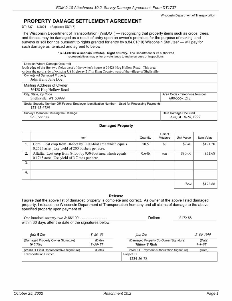
FDM 9-10 Attachment 10.2 Survey Damage Agreement, Form DT1737
October 25, 2002 Attachment 10.2 Page 1
PROPERTY DAMAGE SETTLEMENT AGREEMENT Wisconsin Department of Transportation
DT1737 6/2001 (Replaces ED717)
The Wisconsin Department of Transportation (WisDOT) — recognizing that property items such as crops, trees, and fences may be damaged as a result of entry upon an owner’s premises for the purpose of making land surveys or soil borings pursuant to rights granted for entry by s.84.01(10) Wisconsin Statutes* — will pay for such damage as itemized and agreed to below.
* s.84.01(10) Wisconsin Statutes. Right of Entry. The Department or its authorized representatives may enter private lands to make surveys or inspections.
Location Where Damage Occurred
South edge of the first two fields west of the owner's house at 36428 Hog Hollow Road. This area borders the north side of existing US Highway 217 in King County, west of the village of Shellsville.
Owner(s) of Damaged Property John E and Jane Doe
Mailing Address of Owner 36428 Hog Hollow Road City, State, Zip Code Shellsville, WI 53999
Area Code - Telephone Number 608-555-1212
Social Security Number OR Federal Employer Identification Number – Used for Processing Payments 123-45-6789 Survey Operation Causing the Damage Soil borings
Date Damage Occurred August 18-24, 1999
Damaged Property
Item
Quantity
Unit of Measure
Unit Value
Item Value
1. Corn. Lost crop from 10-foot by 1100-foot area which equals 0.2525 acre. Use yield of 200 bushels per acre.
50.5 bu $2.40 $121.20
2. Alfalfa. Lost crop from 8-foot by 950-foot area which equals 0.1745 acre. Use yield of 3.7 tons per acre.
0.646 ton $80.00 $51.68
3.
4.
Total $172.88
Release I agree that the above list of damaged property is complete and correct. As owner of the above listed damaged property, I release the Wisconsin Department of Transportation from any and all claims of damage to the above specified property upon payment of
One hundred seventy-two & 88/100 - - - - - - - - - - - - - Dollars $172.88 within 30 days after the date of the signatures below. John E Doe 8-30-99 Jane Doe 8-30-1999(Damaged Property Owner Signature) (Date) (Damaged Property Co-Owner Signature) (Date) H I Way 8-30-99 William B Rocke 9-1-99(WisDOT Field Representative Signature) (Date) (WisDOT Payment Authorization Signature) (Date) Transportation District
Project ID
1234-56-78

Page 1
Facilities Development Manual Wisconsin Department of Transportation Chapter 9 Surveying and Mapping Section 20 Spatial Reference Systems
FDM 9-20-1 General February 28, 2001
The discipline of surveying consists of determining or establishing relative positions of points above, on, or beneath the surface of the earth. In Wisconsin, there are two primary spatial reference systems for defining the location of a point:
- The U.S. Public Land Survey System (PLSS).
- The National Spatial Reference System (NSRS).
The PLSS is based on a system of townships, ranges, and sections (see FDM 9-20-5). The PLSS provides the basis for almost all legal descriptions of land.
The NSRS, which includes the former National Geodetic Reference System (NGRS), is a mathematical reference system (see FDM 9-20-10). The NSRS consists of precisely measured networks of geodetic control that support accurate mapping over large areas.
To understand the roles of these reference systems, it is important to recognize that the PLSS was designed for land ownership purposes but not for accurate mapping, and the NSRS was designed for geodetic surveying and mapping but not for land ownership documentation.
Since accurate property maps are becoming essential with digital-based ownership documents, it is important that there be a substantial link between the two reference systems. Methods are needed to utilize the spatial characteristics of the NSRS when addressing the location of landmarks. Fortunately, recent technological developments such as the Global Positioning System (GPS), electronic total station survey instruments, and computer aided drafting (CAD) now make the task of using the PLSS and NSRS together more efficient, economical, and practical.
FDM 9-20-5 The Public Land Survey System July 23, 2015
The interest of the present-day engineer or surveyor in the Public Land Survey System (PLSS) is in the preservation of existing monumentation, retracing of original survey lines and in the subdivision of sections into smaller units. For these reasons, it is imperative that one be familiar with the methods used in the original survey.
The PLSS consists of a rough grid network of surveyed lines and monuments originally established for the purpose of subdividing federal lands prior to public sale. This network covers approximately 72 per cent of the United States and covers 30 states, including Wisconsin. The network partitions the landscape into one mile by one mile areas called ‘sections’, nominally containing 640 acres. Thirty-six sections constitute a township. Each township is identified by its ‘Township’ number (north or south) and its ‘Range’ number (east or west) from an Initial Point. An Initial Point is the origin for PLSS surveys for a given area; there are several Initial Points throughout the United States.
The PLSS was introduced in Wisconsin in 1831 when the Initial Point for the 4th Principal Meridian was established by a government surveyor on what is now the border with Illinois. From this Initial Point, a true north-south line called a principal meridian was run to the north to the limits of the area to be covered. A base line was then extended to the east and west from the initial point as a true parallel of latitude to the limits of the area to be covered. This base line defines the Illinois/Wisconsin state line. The area covered by the 4th Principal Meridian covers all of Wisconsin and parts of Minnesota north and east of the Mississippi River to the Canadian border. The upper peninsula of Michigan is not included in the area covered by the 4th Principal Meridian.
The land was then subdivided into townships by surveying lines that define townships and ranges at 6 mile intervals. The resulting pattern of PLSS Townships and Ranges for the State of Wisconsin is shown in Attachment 5.2. Each township is identified by its number north or south of the base line, followed by its number east or west of the principal meridian. An example is Township 5 North, Range 7 East, of the 4th Principal Meridian. Abbreviated, this becomes T5N, R7E, 4th PM. All townships in Wisconsin are numbered north from the state line.
The subdivision of a township into sections was the final step undertaken by the original land surveyors. Sections were numbered from 1 to 36, beginning in the northeast corner of a township and ending in the southeast corner, as shown in Attachment 5.3. The underlying principle of subdividing townships into sections

FDM 9-20 Spatial Reference Systems
Page 2
was to produce the maximum number of sections with a nominal dimension of 1 mile on a side. A section was the basic unit of land transfer but often land continues to be patented in parcels smaller than a section. Further subdivision of sections continues to be performed by local surveyors under rigid guidelines established by the Bureau of Land Management (BLM). The legal descriptions for nearly every parcel of land in Wisconsin reference the PLSS.
For more detailed information on the PLSS, please consult any introductory surveying textbook or the Manual of Surveying Instructions published by the Bureau of Land Management (BLM),
http://www.blm.gov/pgdata/content/wo/en/prog/more/cadastralsurvey/2009_edition.html
There are three key points to note about the PLSS.
1. It is a legal not a mathematical system. The length of one mile for a section boundary line and 640 acres for its area are nominal. Measurements could vary by hundreds of feet and many acres and still were accepted by the federal government. Easy to understand boundary locations were paramount, so corner locations as monumented by the original surveyors, right or wrong, are the legally recognized corner locations.
2. Perpetuation of original locations of section and quarter section corners is vital to the long term viability of the PLSS. The federal government was responsible for establishment of the PLSS but is not responsible for its maintenance. It is the responsibility of state and local agencies to maintain the PLSS. The department's policy on perpetuation of landmarks is detailed in FDM 9-5-1.
3. PLSS corners and Geodetic Survey Control Stations are two of the most significant types of monuments found within road rights of way. PLSS corners are used to help identify land ownership boundaries and geodetic survey control stations mark a location with a precise elevation and/or latitude and longitude. They are two completely separate entities. If PLSS monuments are disturbed or destroyed, they can be replaced in substantially the same location using local references. Geodetic survey control stations, if disturbed or destroyed, must be replaced and resurveyed in their entirety due to their precision.
There are two key points to remember about the PLSS. First, it is not a mathematical system. The measures of one mile for a section line and 640 acres for the area of a section are only nominal and can be off by hundreds of feet and numbers of acres, respectively. The law has dictated that PLSS boundaries were fixed by surveyors' monuments, not surveyors' measurements (which are never perfect). This leads to the second key point, perpetuation of original locations of section and quarter section corners is vital to the long term viability of the PLSS. The federal government was responsible for establishment of the PLSS but is not responsible for its maintenance. It is the responsibility of state and local agencies to maintain the PLSS. The department's policy on perpetuation of landmarks is detailed in FDM 9-5-1.
LIST OF ATTACHMENTS
Attachment 5.1 Pattern of PLSS Townships & Ranges for Wisconsin
Attachment 5.2 Method of Numbering Sections
FDM 9-20-10 The National Spatial Reference System (NSRS) July 23, 2015
The National Spatial Reference System (NSRS) is a consistent national coordinate system that specifies latitude, longitude, height, scale, gravity, and orientation throughout the nation, as well as how these values change with time. The system is managed by the National Geodetic Survey (NGS). NSRS information is available at the NGS web site:
http://www.ngs.noaa.gov
The NSRS incorporates the horizontal data and the vertical data from the old National Geodetic Reference System. The NSRS, however, can better accommodate positioning with the Global Positioning System (GPS) by use of a three-dimensional geographical coordinate system. When only horizontal positioning is needed, the position may be adequately referenced to a two-dimensional rectangular coordinate system at a single selected height.
For NSRS accuracy standards refer to “Geospatial Positioning Accuracy Standards, Part 2: Standards for Geodetic Networks, FGDC-STD-007.2-1998,” available at:
https://www.fgdc.gov/standards/projects/FGDC-standards-projects/accuracy/part2/chapter2

FDM 9-20 Spatial Reference Systems
Page 3
10.1 Horizontal Network
The horizontal geodetic control network in Wisconsin consists of monumented points (geodetic control stations) with accurately determined horizontal positions. Typically, horizontal control stations in the Wisconsin High Accuracy Reference Network (WI HARN) are spaced 50 km apart. The horizontal position of WI HARN control stations has been determined using GPS which is more accurate than the previously used triangulation methods. WI HARN stations have minimum horizontal accuracy of A-order or B-order (95 percent confidence of 0.01 m to 0.05 m, respectively). The 95 percent confidence for area triangulation was typically 0.2 m to 0.6 m.
Some counties have developed a subsequent set of points within their county as a User Densification Network (UDN) with stations positioned relative to the WI HARN stations. Often referred to as “County HARN” stations, the UDN stations typically are spaced at 25 km, 12 km, and 6 km for primary, secondary, and tertiary control, respectively.
10.2 Vertical Network
The vertical geodetic control network in Wisconsin consists of monumented points (bench marks) with accurately determined elevations (orthometric heights). Typically, bench marks are spaced 1.5 to 2.5 km apart along level lines spaced approximately 50 km apart. In the 1900s, the elevation of a bench mark was determined by the traditional method of measuring successive elevation differences between adjacent bench marks along railroads or highway corridors.
The vertical accuracy of a bench mark was based on the leveling methods used and the difference of two series of vertical measurements between adjacent bench marks. Typically, accuracy ranged from 0.001 m for difference in elevation between two adjacent bench marks to 0.110 m for a vertical control loop. In 1999 GPS technology started to provide a three-dimensional position for selected WI HARN, User Densified Networks (UDN), and project stations with an orthometric height accuracy of 0.020 m.
10.3 Monumentation
To use NSRS data effectively, a system of monumentation must exist. Permanently monumented geodetic control stations and bench marks serve as necessary references for mapping; for Geographic and Land Information Systems; and for planning, design, and construction of engineering projects. When linked to the U.S. Public Land Survey System (PLSS), geodetic control monuments can help perpetuate the system of land ownership. State and local agencies have built upon the WI HARN to further densify the horizontal and vertical geodetic control monumentation.
FDM 9-20-15 Horizontal Datums July 23, 2015
A horizontal datum consists of a geodetic reference surface, an origin, and an orientation. The geodetic reference surface is a mathematically defined ellipsoid, also called a spheroid. A horizontal geodetic control network provides the horizontal positional information (e.g., latitude and longitude) on a horizontal datum. The following horizontal datums1 have been used for transportation projects in Wisconsin.
NAD 27
NAD 83 (1986)
NAD 83 (1991)(see FDM 9-5-10)
NAD 83 (1997)
NAD 83 (2007)
NAD 83 (2011)
Horizontal surveying measurements are made on the surface of the earth (ground), but position computations are usually made on the ellipsoid. It would not be practical to use the actual surface of the earth as a basis for the mathematical positions because the surface is too irregular. Therefore, the ellipsoid is the reference surface for latitude and longitude positions.
15.1 North American Datum of 1927
The North American Datum of 1927 (NAD 27) was used as the primary reference datum for horizontal positions in the United States from 1927 until 1986. NAD 27 has its origin at Meades Ranch in Kansas and is based on the Clarke spheroid of 1866. The Clarke spheroid of 1866 is a regional ellipsoid with a “best fit” for the North American continent. The dimensions of the Clarke spheroid of 1866 are as follows:
Equatorial Radius (a) = 6 378 206.4 m
1 Technically, “NAD 83 (1986),” “NAD 83 (1991),” and “NAD 83 (1997)” are three different adjustments on the NAD 83 datum; however, they are commonly referred to as different datums.

FDM 9-20 Spatial Reference Systems
Page 4
Polar Radius (b)= 6 356 583.8 m
Flattening (a-b)/a= 1/294.978
Because NAD 27 is a based on a regional ellipsoid and not a geocentric (earth centered) one, it became apparent that there was an increasing need to develop a new geocentric datum for worldwide applications. Advances in surveying technology and original datum design limitations also contributed to making NAD 27 obsolete.
15.2 North American Datum of 1983 (1986)
This new geocentric datum is called North American Datum of 1983 (NAD 83). The original name for this datum was NAD 83, but subsequent refinements of station latitude and longitude values necessitated adding an adjustment year after the NAD 83 whenever an adjustment to station coordinates was made by NGS. The original NAD 83 adjustment should be referred to as NAD 83 (1986). Any outdated latitude and longitude positions published by NGS become a permanent part of the superseded data for that station. However, NGS does not provide coordinate or elevation values on outdated adjustments for new stations. NAD 83 (1986) is based on an ellipsoid defined by the Geodetic Reference System of 1980 (GRS 80). GRS 80 is an earth-centered ellipsoid useful for the entire world. The dimensions of the GRS 80 ellipsoid are:
Semimajor axis, a= 6 378 137 m (exact by definition)
Semiminor axis, b= 6 356 752.314 140 3 m (14 significant digits by computation)
Flattening, (a-b)/a= 1/298.257 222 100 88 (14 significant digits by computation)
The North American Datum of 1983, adjustment of 1986 (NAD 83 (1986)) was the first adjustment to fit data to the GRS 80 ellipsoid. Although NAD 83 (1986) is more compatible with Global Positioning System (GPS) technology than its predecessor, NGS could not take full advantage of this "new" technology when performing the first adjustment. Continuing GPS developments, including higher accuracy and greater densification, led to a readjustment of Wisconsin stations in 1991. As a result, NAD 83 (1986) will probably be used very little in the future in Wisconsin.
15.3 North American Datum of 1983 (1991)
In 1988, the National Geodetic Survey (NGS) and WisDOT began establishing what is now called the Wisconsin High Accuracy Reference Network (WI HARN). This is a network of 80 accurate (A-order and B-order) geodetic control stations which are evenly spaced at approximately 50 kilometers throughout the state with additional (first-order) control stations at many Wisconsin airports. The 1990 and 1991 GPS observations of these stations have been adjusted and the results published by NGS as referenced to the North American Datum of 1983, adjustment of 1991 (NAD 83 (1991)). The department currently uses the WI HARN as base control for surveying and large-scale mapping for transportation projects (see FDM 9-5-10).
Information concerning locations and coordinates of the WI HARN stations is at NGS Web site.
http://www.ngs.noaa.gov/
For descriptions of WI HARN stations and other network stations, go to the NGS Data Sheets Web site and select a method of retrieval.
http://www.ngs.noaa.gov/cgi-bin/datasheet.prl
15.4 North American Datum of 1983 (1997)
During the 1997 WI HARN survey NGS and WisDOT observed many of the stations previously observed in 1990 and 1991 during the first WI HARN survey, observed new stations at airports, and observed stations which were tied to the International Great Lakes Datum (see FDM 9-20-20). The 1997 observations have been adjusted and published by NGS as referenced to the North American Datum of 1983, adjustment of 1997 (NAD 83 (1997)).
15.5 North American Datum of 1983 (2007)
In 2007, the National Geodetic Survey completed a nationwide adjustment of nearly all historic documented GPS projects. This adjustment includes only GPS surveyed projects and no longer includes historic triangulation observations. Older triangulation stations will no longer be updated to a new adjustment unless they are part of a GPS project. Previous to this adjustment, projects were usually adjusted state-by-state, resulting in a good fit within a state, but sometimes there were accuracy issues between adjoining states. The 2007 national horizontal adjustment provided more reliable horizontal coordinate results between adjoining states. This adjustment was constrained to the NGS Continuously Operating Reference Stations (CORS) network realization known as NAD 83 (CORS 96). The 2007 horizontal adjustment is identified as NAD 83 (2007).
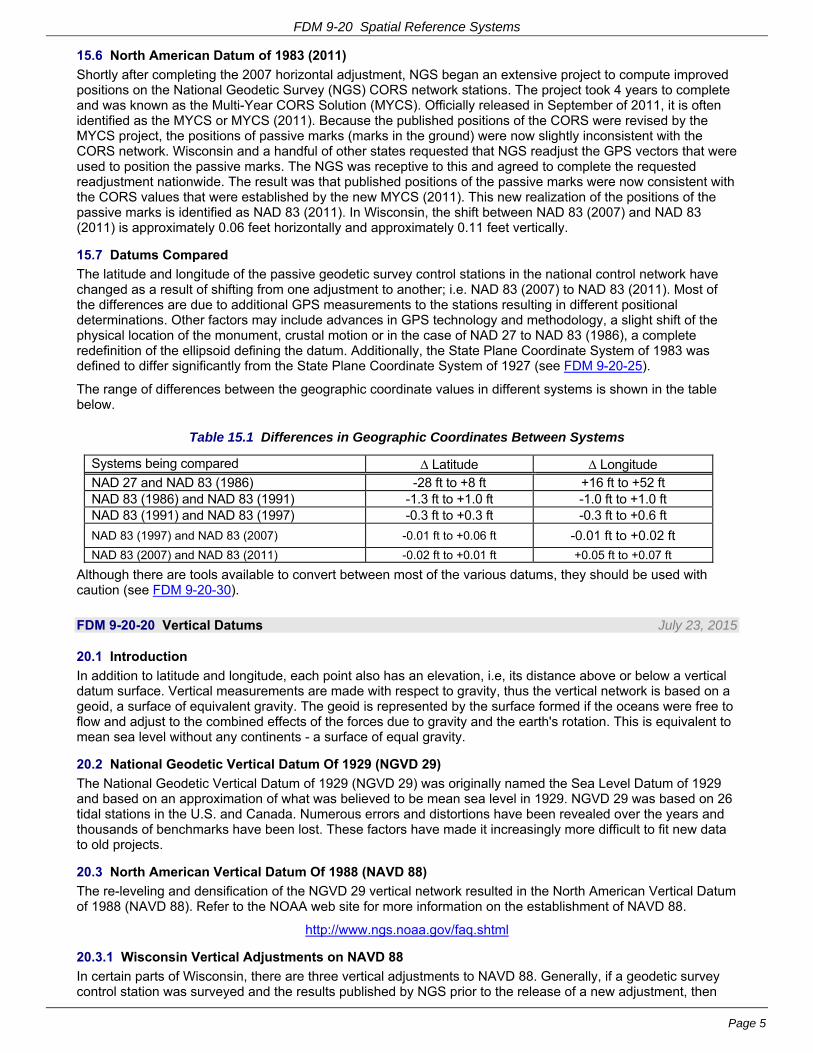
FDM 9-20 Spatial Reference Systems
Page 5
15.6 North American Datum of 1983 (2011)
Shortly after completing the 2007 horizontal adjustment, NGS began an extensive project to compute improved positions on the National Geodetic Survey (NGS) CORS network stations. The project took 4 years to complete and was known as the Multi-Year CORS Solution (MYCS). Officially released in September of 2011, it is often identified as the MYCS or MYCS (2011). Because the published positions of the CORS were revised by the MYCS project, the positions of passive marks (marks in the ground) were now slightly inconsistent with the CORS network. Wisconsin and a handful of other states requested that NGS readjust the GPS vectors that were used to position the passive marks. The NGS was receptive to this and agreed to complete the requested readjustment nationwide. The result was that published positions of the passive marks were now consistent with the CORS values that were established by the new MYCS (2011). This new realization of the positions of the passive marks is identified as NAD 83 (2011). In Wisconsin, the shift between NAD 83 (2007) and NAD 83 (2011) is approximately 0.06 feet horizontally and approximately 0.11 feet vertically.
15.7 Datums Compared
The latitude and longitude of the passive geodetic survey control stations in the national control network have changed as a result of shifting from one adjustment to another; i.e. NAD 83 (2007) to NAD 83 (2011). Most of the differences are due to additional GPS measurements to the stations resulting in different positional determinations. Other factors may include advances in GPS technology and methodology, a slight shift of the physical location of the monument, crustal motion or in the case of NAD 27 to NAD 83 (1986), a complete redefinition of the ellipsoid defining the datum. Additionally, the State Plane Coordinate System of 1983 was defined to differ significantly from the State Plane Coordinate System of 1927 (see FDM 9-20-25).
The range of differences between the geographic coordinate values in different systems is shown in the table below.
Table 15.1 Differences in Geographic Coordinates Between Systems
Systems being compared Latitude Longitude NAD 27 and NAD 83 (1986) -28 ft to +8 ft +16 ft to +52 ft NAD 83 (1986) and NAD 83 (1991) -1.3 ft to +1.0 ft -1.0 ft to +1.0 ft NAD 83 (1991) and NAD 83 (1997) -0.3 ft to +0.3 ft -0.3 ft to +0.6 ft
NAD 83 (1997) and NAD 83 (2007) -0.01 ft to +0.06 ft -0.01 ft to +0.02 ft
NAD 83 (2007) and NAD 83 (2011) -0.02 ft to +0.01 ft +0.05 ft to +0.07 ft
Although there are tools available to convert between most of the various datums, they should be used with caution (see FDM 9-20-30).
FDM 9-20-20 Vertical Datums July 23, 2015
20.1 Introduction
In addition to latitude and longitude, each point also has an elevation, i.e, its distance above or below a vertical datum surface. Vertical measurements are made with respect to gravity, thus the vertical network is based on a geoid, a surface of equivalent gravity. The geoid is represented by the surface formed if the oceans were free to flow and adjust to the combined effects of the forces due to gravity and the earth's rotation. This is equivalent to mean sea level without any continents - a surface of equal gravity.
20.2 National Geodetic Vertical Datum Of 1929 (NGVD 29)
The National Geodetic Vertical Datum of 1929 (NGVD 29) was originally named the Sea Level Datum of 1929 and based on an approximation of what was believed to be mean sea level in 1929. NGVD 29 was based on 26 tidal stations in the U.S. and Canada. Numerous errors and distortions have been revealed over the years and thousands of benchmarks have been lost. These factors have made it increasingly more difficult to fit new data to old projects.
20.3 North American Vertical Datum Of 1988 (NAVD 88)
The re-leveling and densification of the NGVD 29 vertical network resulted in the North American Vertical Datum of 1988 (NAVD 88). Refer to the NOAA web site for more information on the establishment of NAVD 88.
http://www.ngs.noaa.gov/faq.shtml
20.3.1 Wisconsin Vertical Adjustments on NAVD 88
In certain parts of Wisconsin, there are three vertical adjustments to NAVD 88. Generally, if a geodetic survey control station was surveyed and the results published by NGS prior to the release of a new adjustment, then

FDM 9-20 Spatial Reference Systems
Page 6
the station will likely have an elevation in both the old and new adjustment. Any outdated elevations or coordinates published by NGS become a permanent part of the superseded data for that station. However, NGS does not provide coordinate or elevation values on outdated adjustments for new stations. The vertical adjustments in Wisconsin are referred to as NAVD 88 (1991), NAVD 88 (2007), and NAVD 88 (2012). WisDOT no longer uses the datum tag of NAVD 88 without an adjustment year because of the potential confusion among the three adjustments. The original NAVD 88 adjustment is called NAVD 88 (1991). The datum tag NAVD 88 without an adjustment year shall no longer be used.
20.3.2 Comparison of NGVD 29 to NAVD 88 (1991)
The "zero" line for the shift between NGVD 29 and NAVD 88 (1991) values runs through the center of Wisconsin, resulting in a minimal impact for the state. In Wisconsin, the shifts in elevation between the two datums range from +0.15 to -0.25 foot.
20.3.3 NAVD 88 (2007)
The Wisconsin Height Modernization Program (HMP) (see FDM 9-5-1.2) has produced a large quantity of differential leveling data that identified some updates to geodetic control station elevations that were originally published as NAVD 88 (1991). Because there were a large number of changes to previously published elevations, NGS did an adjustment of leveling data in 2007 in the southern and eastern portion of the state. At some geodetic survey control stations, the differences between the NAVD 88 (1991) and NAVD 88 (2007) values were as much as 0.25 foot.
20.3.4 NAVD 88 (2012)
The addition of more HMP leveling data in the Door County area and in the northwestern areas of Wisconsin revealed issues trying to match elevations of previous work done in Minnesota, Michigan, and along the Great Lakes level network (see FDM 9-20-20.4). Consequently, all the HMP vertical data finished to this point was adjusted simultaneously to determine the 2012 adjustment. The 2012 adjustment was constrained similarly to the 1991 adjustment; therefore, the elevations of the 2012 adjustment are generally closer to the 1991 elevations than the 2007.
20.4 International Great Lakes Datum (IGLD)
Persons doing survey work along the rivers and lakes of the Great Lakes system will often encounter the International Great Lakes Datum (IGLD 1955 or IGLD 1985). The geodetic basis for level networks such as NGVD 29 and NAVD 88 is known as "orthometric heights or elevations." For these heights, one equipotential surface, mean sea level is selected for the reference surface to which heights are measured. The International Great Lakes Datum uses dynamic height, which is referenced to the equipotential surface at a particular point. The dynamic height varies with the elevation and latitude of the point.
The IGLD is based on water levels that are readjusted every 25 to 35 years to correct for movement of the earth's crust. This rate of movement is not uniform across the great lakes, causing the benchmarks to shift over time, both with respect to each other and with respect to the initial reference point.
It is not uncommon for transportation improvement projects along the Great Lakes to require elevations in both types of elevation systems. A conversion factor relating the land and water datums must be computed for each project for which a relationship is desired. This can become a very complex subject because of the non-uniformity of crustal movement, combined with different reference surfaces. The best source of information on conversion factors is the Office of Ocean and Earth Sciences, a part of the National Oceanic and Atmospheric Administration. When provided with a NGVD 29 benchmark value, they can compute a conversion factor suitable for a particular project site.
The recent incorporation of IGLD(85) into NAVD 88 have brought these two datums closer together. Today they are essentially the same datum, the only remaining difference being the published heights (dynamic vs. orthometric, respectively).
20.5 Local Vertical Datums
Many public and private entities have established local vertical datums unique to a given area. The basis for these local vertical datums may be as simple as assigning elevation zero to the outlet of the sewer line at the sewage treatment plant, or assigning an arbitrary elevation to the city hall steps.
Local vertical datums shall not be used for WisDOT projects without written permission of the Region Survey Coordinator in consultation with the Central Office Surveying & Mapping Section Chief (see FDM 9-5-10).

FDM 9-20 Spatial Reference Systems
Page 7
FDM 9-20-25 Coordinate Systems February 28, 2001
25.1 Map Projections
A two-dimensional coordinate system using rectangular coordinates (X and Y) is convenient for mapping, measuring project distances, and computing engineering quantities. Unfortunately, the surface of the earth is three-dimensional and ignoring the third dimension introduces errors that increase in magnitude as the project area expands. One way of decreasing this distortion error is to use a projection that defines a mathematical correlation between a three-dimensional reference surface and a two-dimensional developable surface. The two most common projections used to minimize the distortion in shape, area, scale, and direction are the Lambert conformal conical map projection and the transverse Mercator map projection.
25.1.1 Lambert Conformal Conical Map Projection
The Lambert conformal conical map projection uses a cone whose axis is coincident with the axis of rotation of the earth. The cone may be tangent to the reference surface at one predetermined parallel of latitude or cut the reference surface at two predetermined parallels of latitude (see Attachment 25.1, Detail A). If the area of the cone between the two parallels of latitude is developed into a two-dimensional planar surface, it will appear as in Attachment 25.1, Detail B. From a study of these figures, the following observations can be made:
- The meridians (lines of longitude) on the reference surface will appear as straight lines converging at the apex of the cone.
- The parallels (lines of latitude) will appear as segments of concentric circles whose center is the apex of the cone.
- Since the surface of the cone and the reference surface are coincident at the standard parallels (point A to point B, and point C to point D in Attachment 25.1 Detail A and B), the scale along these lines will be exact.
- The scale will be smaller in the area between the standard parallels than along the standard parallels. The scale will be larger in the area outside of the standard parallels than along the standard parallels.
- The closer together the standard parallels are chosen, the more nearly the surface of the projection (i.e., the cone) becomes coincident with the reference surface and the more nearly the projection becomes conformal (distortions are minimized).
- The Lambert projection can be extended indefinitely in an east-west direction without affecting the accuracy of the projection. This projection is more suitable for an area with its greater extent in the east-west direction.
25.1.2 Transverse Mercator Map Projection
The transverse Mercator map projection uses a cylinder whose axis is in the equatorial plane. The cylinder is either tangent to the reference surface along a meridian (the radius of the cylinder is the same as the radius of the reference surface) or the cylinder cuts the reference surface along two lines (the radius of the cylinder is slightly less than the radius of the reference surface). Only the latter case will be addressed further (see Attachment 25.1, Detail C) As the cylinder is developed into a plane surface, it will appear as in Attachment 25.1, Detail D. From a study of these figures, the following observations can be made:
- The meridians (lines of longitude) will appear on the plane surface as curved lines, except the central meridian which will appear as a straight line.
- The parallels (lines of latitude) will appear on the plane surface will appear as curved lines.
- Since the surface of the cylinder and the reference surface are coincident at two lines (point A to point B and point C to point D in Attachment 25.1 Detail C and D), the scale along these lines will be exact.
- The scale will be smaller in the area between the two coincident lines than along the two coincident lines. The scale will be larger in the area outside of the two coincident lines than along the two coincident lines.
- The closer together the two coincident lines are chosen, the more nearly the surface of the projection (i.e., the cylinder) becomes coincident with the reference surface and the more nearly the projection becomes conformal (distortions are minimized).
- The transverse Mercator projection can be extended indefinitely in a north-south direction without affecting its accuracy. This projection is more suitable for an area with its greater extent in the north-south direction.
25.2 Geographic Coordinate System
The global coordinate system of latitude and longitude has angular units (degrees, minutes, and seconds of arc). While this works well for exchanging point data, such units are very difficult to use for computing typical

FDM 9-20 Spatial Reference Systems
Page 8
quantities such as length and area. Length and area computations are performed more easily using rectangular coordinates.
25.3 Rectangular Coordinate Systems
The rectangular coordinate systems used in Wisconsin can be described as being either a regional, local, area, or project rectangular coordinate system.
25.3.1 Regional System
This system is commonly used for mapping a large area such as in a geographic information system (GIS) or computer-aided design (CAD) application. The advantage of a regional system is a seamless map over several counties or the entire state. Disadvantages include less accuracy than local systems and problems related to converting the map data from grid coordinates to ground values needed for high-accuracy field work. The regional rectangular coordinate systems used in Wisconsin include the State Plane Coordinate (SPC) system (see FDM 9-20-26), the Universal Transverse Mercator (UTM) coordinate system, and the Wisconsin Transverse Mercator (WTM) coordinate system.
The UTM coordinate system is a global system developed by the U.S. Department of Defense (DOD) for military purposes and the civilian component of the Army Corps of Engineers. The UTM coordinate system has 60 north-south zones arranged edge-to-edge around the equator, each zone being 6 degrees of longitude wide. Zones are numbered from west to east beginning at the 180th meridian. Wisconsin lies partly in UTM zone 15 and partly in UTM zone 16 (see Attachment 25.2). Each UTM zone has an origin on the equator at the intersection of the zone central meridian and the equator. A false easting value of 500,000 meters was assigned to the central meridian to avoid negative coordinate values. Defining parameters for zones 15 and 16 may be found in the “Wisconsin Coordinate Reference System” booklet published in 2009 by the Wisconsin State Cartographer’s Office available at the SCO web site:
http://www.sco.wisc.edu/images/stories/publications/WisCoordRefSys_January2012.pdf
The Wisconsin Department of Natural Resources developed the WTM projection, centered on the 90th meridian, to avoid splitting the state into two UTM zones, as had been done with the DOD UTM coordinate system. This projection created one standard-UTM-size zone (sometimes referred to as UTM Zone 15( ) to cover the entire state (see Attachment 25.3). WTM is an example of a local system designed and created to match a particular need. Defining parameters for WTM 27 and WTM 83 may be found in the “Wisconsin Coordinate Reference System” booklet published in 2009 by the Wisconsin State Cartographer’s Office available at the SCO web site:
http://www.sco.wisc.edu/images/stories/publications/WisCoordRefSys_January2012.pdf
25.3.2 Local System
This system is typically used for smaller areas, often the size of a county, to minimize scale distortions that would occur with a larger regional projection. Advantages of a local system include better "nominal" accuracy and grid (mapped) lengths which are closer to ground lengths. In many cases the difference in lengths is negligible and there is no need to convert between grid lengths and ground lengths. The disadvantages of a local system include a lack of consistent coordinates across local boundaries and the constant need to transform data obtained from outside the local area. The Wisconsin County Coordinate System (WCCS) is an example of a local coordinate system (see FDM 9-20-27).
25.3.3 Area Project System
This system may be established as a simplified version of a regional or local rectangular coordinate system. By using a single combination factor for the entire project area, the computation between grid and ground lengths or coordinates will be simplified. Project coordinates may be necessary when mapping and computations are performed on the grid, yet the final stakeout of right-of-way points, alignment points, etc. must be done with ground distances. The process used to transform the grid coordinate positions to the ground coordinate positions is known as grid to ground coordinate conversion (see FDM 9-20-40). The project coordinate systems that use a combination factor for an area cannot be directly converted to another coordinate system without first converting the coordinates back to their grid values. Past experience has found this to be a confusing issue as data are shared between surveys, design, real estate, construction, and the public.
25.3.4 Project System
This system can be as simple as an “assumed” coordinate system or can be very similar to a local coordinate system but only valid within the area of a transportation project. An “assumed” project rectangular coordinate system may be used on a small project where it is not economical or feasible to establish geodetic control. For a small project, assuming a coordinate system with an origin of X=10,000 and Y=10,000 may be a reasonable

FDM 9-20 Spatial Reference Systems
Page 9
choice; however, follow FDM 9-5-10. The disadvantage of using an “assumed” project coordinate system is that the system is not mathematically related to any other established coordinate system. Most likely, future work in the same area will not be able to use the survey data previously acquired; therefore, additional expense will occur to survey the same area again. An “assumed” project coordinate system should be requested for a project only after knowledgeable consideration of potential resurvey costs and the inability to relate the project coordinates to other global coordinate systems.
25.4 Using More Than One Coordinate System
Coordinate systems (geographic or rectangular) referenced to the same horizontal datum, are mathematically related and positional data can be accurately converted from one system to another (see FDM 9-20-30). For example, the coordinates of a point initially in SPC on NAD 83 (1991), may be converted to WCCS on NAD 83 (1991), to another county in WCCS on NAD 83 (1991), or to geographic coordinates (latitude and longitude), and vice versa.
LIST OF ATTACHMENTS
Attachment 25.1 Map Projection
Attachment 25.2 Universal Transverse Mercator Coordinate System
Attachment 25.3 Wisconsin Transverse Mercator Coordinate System
FDM 9-20-26 Wisconsin State Plane Coordinate System February 28, 2001
The State Plane Coordinate (SPC) system has historically been the most used rectangular coordinate system in Wisconsin. The SPC system is based on three separate Lambert conformal conic map projections, each of which covers one of the zones shown in Attachment 26.1. Because the SPC system is intended for local applications, the boundaries of these zones follow county lines; however, the system is usable for quite some distance beyond the county line with minimal loss of accuracy. The SPC system eliminates problems created by having individual surveys with different project coordinate systems. It provides a common grid plane for all surveys in the zone and each zone is mathematically related to one another. Each zone has a false origin to the south and west of the zone so that all coordinates will have positive values. Defining parameters for SPC systems are found in the “Wisconsin Coordinate Reference Systems” booklet published in 2009 by the Wisconsin State Cartographer’s Office available at the SCO web site:
http://www.sco.wisc.edu/images/stories/publications/WisCoordRefSys_January2012.pdf
Grid coordinate values for the Wisconsin SPC system are typically within the ranges listed below. If values outside of these ranges are encountered, consult with the District Survey Coordinator or the Surveying & Mapping Section.
System SPC 27 (feet) SPC 83 (meters) SPC 83 (feet)
North Zone
Easting 1,252,000 to 2,508,000 372 000 to 755 000 1,221,000 to 2,476,000 Northing 77,000 to 715,000 23 000 to 218 000 77,000 to 715,000
Central Zone
Easting 1,252,000 to 2,829,000 372 000 to 853 000 1,221,000 to 2,798,000 Northing 54,000 to 747,000 16 000 to 228 000 54,000 to 747,000
South Zone
Easting 1,617,000 to 2,659,000 483 000 to 801 000 1,586,000 to 2,627,000 Northing 186,000 to 873,000 57 000 to 266 000 186,000 to 873,000
If an easting coordinate value in feet is less than 1,200,000 in Wisconsin, that coordinate value is not a SPC system value. Some projects have used easting coordinate values of 1 or 2 million less than the SPC system value. Those projects are on a local coordinate system and should not be confused with projects on the SPC system.
LIST OF ATTACHMENTS
Attachment 26.1 Wisconsin State Plane Coordinate System

FDM 9-20 Spatial Reference Systems
Page 10
FDM 9-20-27 Wisconsin County Coordinate System July 22, 2009
The Wisconsin County Coordinate System (WCCS) was developed for WisDOT to avoid the confusion associated with grid versus ground coordinates and distances on construction plans and right-of-way plats. The WCCS was developed based on NAD 83 (1991). Current WisDOT policy (see FDM 9-5-10) is to use WCCS or the Wisconsin Coordinate Reference Systems (WISCRS) (see FDM 9-20-28) for all large-scale (small-area) conformal mapping (1:4,800 or larger). Coordinate values listed on construction plans and right-of-way plats will now be listed in the WCCS and indicated by “Y=” and “X=.” Because the reference surface occurs at the most commonly occurring ground level in the county, there is no longer a need to convert between grid and ground distances as they are essentially equal for all large-scale mapping.
Caution: Precise geodetic control surveys are not to be conducted in WCCS, use latitude and longitude in a geographic coordinate system.
The WCCS covers the State of Wisconsin with 59 separate sets of projection-defining parameters to cover the 72 zones (see Attachment 1). Some adjacent counties have common parameters but each county has a unique zone number. Defining parameters for the 72 county zones may be found in the “Wisconsin Coordinate Reference Systems” booklet published in 2009 by the Wisconsin State Cartographer’s Office or at the SCO web site:
http://www.sco.wisc.edu/images/stories/publications/WisCoordRefSys_January2012.pdf
When using the WCCS for a project in multiple counties, it is important to consider accuracy and legal requirements as data are acquired near or across a county line. Usually loss of accuracy will not be critical unless there is a great difference in elevation between the counties. Legally, there may be a requirement to file documents using the zone of the resident county. Specific requirements should be checked for each project. General requirements are:
- For transportation projects that are continuous in more than one county, the WCCS zone used should change at the county line. Photogrammetric mapping will be provided to the requester with approximately 1000 feet (305 m) of overlap of mapping in both zones. Design plans and plats should be completed in the respective county coordinate system zone.
- For transportation projects that extend into an adjacent county approximately 1000 feet (305 m) or less, the WCCS zone used may remain that of the primary county. Those projects that extend more than approximately 1000 feet (305 m) into the next county should follow the guidance in the previous paragraph.
- For transportation projects that tend to parallel the county line mostly within 1000 feet (305 m) of the county line, the WCCS zone used should be the zone for county A (county A to be selected by the requester which will usually be the county with the majority of the project). The WCCS zone for county A may be used on the plat to be recorded in county B. In this case, it is crucial to document the WCCS zone used and to clearly label the coordinate zone on plans, plats, computer files, and all other documentation.
- For transportation projects which tend to parallel the county line more than 1000 feet (305 m) from the county line, the WCCS zone used should changed at the county line. Photogrammetric mapping will be provided to the requester with approximately 1000 feet (305 m) of overlap of mapping in both WCCS zones. Design plans and plats should be completed in the respective county WCCS zone.
LIST OF ATTACHMENTS
Attachment 27.1 Wisconsin County Coordinate System
Attachment 27.2 Wisconsin County Coordinate System Zones
FDM 9-20-28 Wisconsin Coordinate Reference System July 22, 2009
The Wisconsin Coordinate Reference Systems (WISCRS) was developed as a mathematical alternative to the Wisconsin County Coordinate System (WCCS) (see FDM 9-20-27). Details on the development of WISCRS and the mathematical differences are available at the State Cartographer's Office (SCO) Web site:
http://www.sco.wisc.edu/
WISCRS may be used in any application that WCCS may be used. The difference in coordinate values computed by the two systems will normally be less than approximately 0.006 feet and never greater than 0.016 feet, with one exception. Because the values computed may not be the same, the coordinate values
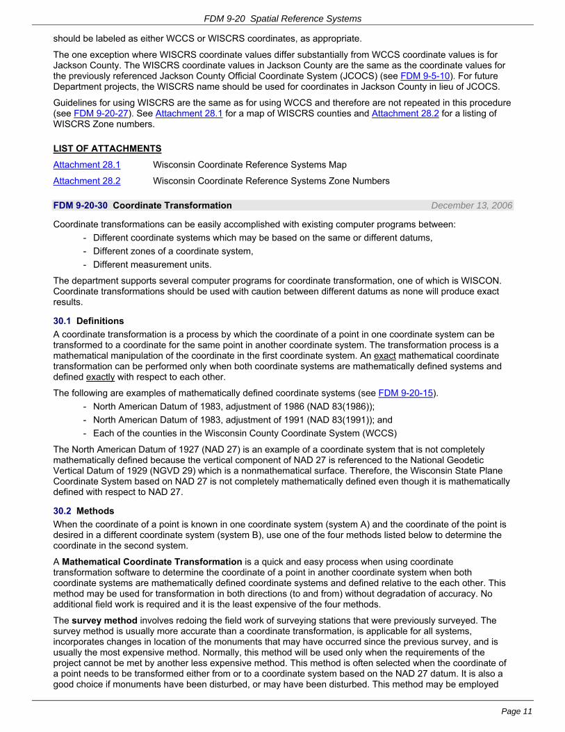
FDM 9-20 Spatial Reference Systems
Page 11
should be labeled as either WCCS or WISCRS coordinates, as appropriate.
The one exception where WISCRS coordinate values differ substantially from WCCS coordinate values is for Jackson County. The WISCRS coordinate values in Jackson County are the same as the coordinate values for the previously referenced Jackson County Official Coordinate System (JCOCS) (see FDM 9-5-10). For future Department projects, the WISCRS name should be used for coordinates in Jackson County in lieu of JCOCS.
Guidelines for using WISCRS are the same as for using WCCS and therefore are not repeated in this procedure (see FDM 9-20-27). See Attachment 28.1 for a map of WISCRS counties and Attachment 28.2 for a listing of WISCRS Zone numbers.
LIST OF ATTACHMENTS
Attachment 28.1 Wisconsin Coordinate Reference Systems Map
Attachment 28.2 Wisconsin Coordinate Reference Systems Zone Numbers
FDM 9-20-30 Coordinate Transformation December 13, 2006
Coordinate transformations can be easily accomplished with existing computer programs between:
- Different coordinate systems which may be based on the same or different datums,
- Different zones of a coordinate system,
- Different measurement units.
The department supports several computer programs for coordinate transformation, one of which is WISCON. Coordinate transformations should be used with caution between different datums as none will produce exact results.
30.1 Definitions
A coordinate transformation is a process by which the coordinate of a point in one coordinate system can be transformed to a coordinate for the same point in another coordinate system. The transformation process is a mathematical manipulation of the coordinate in the first coordinate system. An exact mathematical coordinate transformation can be performed only when both coordinate systems are mathematically defined systems and defined exactly with respect to each other.
The following are examples of mathematically defined coordinate systems (see FDM 9-20-15).
- North American Datum of 1983, adjustment of 1986 (NAD 83(1986));
- North American Datum of 1983, adjustment of 1991 (NAD 83(1991)); and
- Each of the counties in the Wisconsin County Coordinate System (WCCS)
The North American Datum of 1927 (NAD 27) is an example of a coordinate system that is not completely mathematically defined because the vertical component of NAD 27 is referenced to the National Geodetic Vertical Datum of 1929 (NGVD 29) which is a nonmathematical surface. Therefore, the Wisconsin State Plane Coordinate System based on NAD 27 is not completely mathematically defined even though it is mathematically defined with respect to NAD 27.
30.2 Methods
When the coordinate of a point is known in one coordinate system (system A) and the coordinate of the point is desired in a different coordinate system (system B), use one of the four methods listed below to determine the coordinate in the second system.
A Mathematical Coordinate Transformation is a quick and easy process when using coordinate transformation software to determine the coordinate of a point in another coordinate system when both coordinate systems are mathematically defined coordinate systems and defined relative to the each other. This method may be used for transformation in both directions (to and from) without degradation of accuracy. No additional field work is required and it is the least expensive of the four methods.
The survey method involves redoing the field work of surveying stations that were previously surveyed. The survey method is usually more accurate than a coordinate transformation, is applicable for all systems, incorporates changes in location of the monuments that may have occurred since the previous survey, and is usually the most expensive method. Normally, this method will be used only when the requirements of the project cannot be met by another less expensive method. This method is often selected when the coordinate of a point needs to be transformed either from or to a coordinate system based on the NAD 27 datum. It is also a good choice if monuments have been disturbed, or may have been disturbed. This method may be employed

FDM 9-20 Spatial Reference Systems
Page 12
when the position for some stations in a project is based on NAD 83 (1991) and others on NAD 83 (1997).
The readjustment method is a good method to select when the previous ground survey data are still available and valid but the starting point coordinate of the previous survey is in question, was erroneously selected, or does not have a coordinate in a mathematically defined system. Once a revised coordinate of the starting point is available in coordinate system B, then the original survey measurements are used to readjust the entire project in coordinate system B.
The interpolation method involves transforming coordinates using an interpolation of shift values between the two coordinate systems. The primary purpose of this method is for transforming coordinates either to or from a coordinate system that is not completely mathematically defined relative to the other coordinate system; e.g., NAD 83 (1991) to NAD 83 (1997).
30.3 Horizontal Transformation
A coordinate transformation may be performed between various coordinate systems based on various datums (see FDM 9-20-25) used for transportation projects with the following accuracy.
30.3.1 Exact Coordinate Transformation
A coordinate transformation between any two of the below listed coordinate systems within a datum adjustment, or between any two zones within a system will yield exact results.
30.3.1.1 NAD 27
Geographical coordinates (i.e., latitude and longitude)
State Plane Coordinates (north, central, or south zone)
Universal Transverse Mercator Coordinate System
Wisconsin Transverse Mercator Coordinate System
30.3.1.2 NAD 83 (1986)
Geographical coordinates (i.e., latitude and longitude)
State Plane Coordinates (north, central, or south zone)
Universal Transverse Mercator Coordinate System
Wisconsin Transverse Mercator Coordinate System
30.3.1.3 NAD 83 (1991)
Geographical coordinates (i.e., latitude and longitude)
State Plane Coordinates (north, central, or south zone)
Universal Transverse Mercator Coordinate System
Wisconsin Transverse Mercator Coordinate System
Wisconsin County Coordinate System (any zone)
Jackson County Official Coordinate System
30.3.1.4 NAD 83 (1997)
Geographical coordinates (i.e., latitude and longitude)
Wisconsin State Plane Coordinate System (north, central, or south zone)
Universal Transverse Mercator Coordinate System
Wisconsin Transverse Mercator Coordinate System
Wisconsin County Coordinate System (any zone)
Jackson County Official Coordinate System
30.3.2 Approximate Coordinate Transformation
A coordinate transformation between any datum adjustments listed above and any NAD 27 based coordinate system will yield approximate results.

FDM 9-20 Spatial Reference Systems
Page 13
30.3.3 Special Considerations
The parameters to define a coordinate transformation between a system based on NAD 83 (1997) and a system based on NAD 83 (1991) have not been defined by NGS. NGS does not plan to publish program parameters for a coordinate transformation between NAD 83 (1991) and NAD 83 (1997). The difference between NAD 83 (1991) and NAD 83 (1997) HARN station positions averages approximately ±0.14 ft, which is less than half of the accuracy of the NADCON computation.
When a survey has some points with NAD 83 (1997) coordinates and some on a different coordinate system, use the "survey method" for most situations to get all stations on the same system. Some situations may warrant considering the "readjustment method" or the "interpolation method."
30.4 Vertical Transformation
A coordinate transformation of a height (elevation) between NGVD 29 and the North American Vertical Datum of 1988 (NAVD 88), or between NAVD 88 and a GRS 80 ellipsoid height associated with an NAD 83 horizontal position will yield approximate results.
30.5 Software
30.5.1 Original NADCON
The National Geodetic Survey (NGS) developed the horizontal data transformation computer program NADCON to transform coordinates for low-accuracy surveying or navigation purposes. NADCON is the Federal Standard for NAD 27 to NAD 83 datum transformations. At the 95-percent confidence level, NADCON has an expected horizontal accuracy of ±1.0 ft within the conterminous United States for transformations between NAD 27 and NAD 83 (1986). Accuracy is dependent upon the density of control and the quality of control surveyed on NAD 27.
30.5.2 Revised NADCON
The revised version of NADCON will also transform coordinates to the High Accuracy Reference Network (HARN)2. At the 95-percent confidence level, NADCON has an expected horizontal accuracy of ±0.33 ft for transformations between NAD 83 (1986) and NAD 83 (1991) and an expected horizontal accuracy of ±1.33 ft for transformations between NAD 27 and NAD 83 (1991).
30.5.3 VERTCON
NGS developed the computer program VERTCON to compute the modeled difference in orthometric height between NAVD 88 and NGVD 29 for a given location specified by latitude and longitude. At the 95-percent confidence level, VERTCON software using the VERTCON 2.0 model has an expected difference in orthometric height accuracy of ±0.13 ft for transformations between NAVD 88 and NGVD 29.
30.5.4 WISCON
The department has developed the computer program WISCON which combines the computations of original/revised NADCON and VERTCON into a single program. WISCON also provides conversion between geographical and rectangular coordinate systems, as well as conversion of measurement units (the U.S. Survey Foot to the meter or the meter to the U.S. Survey Foot). WISCON is a Windows-based program for coordinate and datum transformation among geographic coordinate systems and rectangular coordinate systems based on various horizontal and vertical datum combinations. For more information on WISCON see the State Cartographer’s web page:
http://www.sco.wisc.edu/
For information on the current version of WISCON being used by the department, contact the Chief Surveying & Mapping Engineer at 608-267-9639.
30.6 Interpolation
The department does not currently use or support software that can transform the coordinate of a point in one coordinate system (system A) to a second coordinate system (system B) based only on the coordinates of nearby points whose coordinates are known in both coordinate systems. Special situations may warrant using interpolation based on a user-developed spreadsheet or on specific application software if it is suitable and available.
30.7 Trimble Geometrics Office (TGO)
Trimble Geomatics Office (TGO) is a program used to view and manipulate data collected with the Trimble
2 The program parameters used for the HARN are those based on the NAD 83 (1991) HARN data for Wisconsin.

FDM 9-20 Spatial Reference Systems
Page 14
Survey Controller. TGO comes with a utility program called Coordinate System Manager. This utility program allows the user to define various coordinate systems and datums, and then transform the coordinate of a point between these systems. The process for doing a transformation involves opening a project in TGO in one of the defined coordinate systems, importing points to be transformed, changing the project properties to another one of the defined coordinate systems, and then exporting the points from the project with their changed coordinate values.
FDM 9-20-35 Combination Factor Selection February 28, 2001
This procedure explains using a combination factor with the Wisconsin State Plane Coordinate (SPC) System. When working with the Wisconsin County Coordinate System (WCCS) refer to FDM 9-20-27.
The combination factor is the ratio of the length of a line on a map projection (often called the “grid” distance) to the horizontal length of the corresponding line at ground elevation. The combination factor value is calculated as the product of an elevation or sea level factor and a scale factor. Use elevation factor with North American Datum of 1983 (NAD 83) and sea level factor with North American Datum of 1927 (NAD 27).
The elevation or sea level factor and the scale factor are computed and applied separately for each measured distance in precise surveys. These computations are part of the least squares adjustment program used by the department. For less precise surveys, a combination factor is used to obtain a grid coordinate or grid distance from a ground coordinate or ground distance. For previous projects, often the average ground elevation was used for all work in a county or township. The procedure for deriving a combination factor involves the following steps.
35.1 Elevation or Sea Level Factor
35.1.1 Elevation Factor
The elevation factor is the ratio of the length of a line on the surface of the ellipsoid for NAD 83 to the horizontal length of the corresponding line at ground elevation. The elevation factor value is calculated as the ratio of the mean radius of the earth divided by the sum of the mean radius of the earth and the mean ellipsoidal height of the line.
Elevation Factor = R
R + h
Where:
R is the mean radius of the earth of 20,906,000 feet (6 372 000 m), and
h is the mean ellipsoidal height of the line above the ellipsoid in feet (or m).
The value for h may be selected for a line or for an area (see below under “Point or Area Elevation”). In Wisconsin, the value of h will always be positive. The mean radius of the earth may be used as the value for R for all but the most precise surveys.
The distance on the surface of the ellipsoid, the geodetic distance, is calculated by the equation:
Geodetic Distance = Horizontal Distance * Elevation Factor
35.1.2 Sea Level Factor
The sea level factor is the ratio of the length of a line on the surface of the ellipsoid for NAD 27 to the horizontal length of the corresponding line at ground elevation. The sea level factor value is calculated as the ratio of the mean radius of the earth divided by the sum of the mean radius of the earth and the mean height of the line above mean sea level, i.e., the National Geodetic Vertical Datum of 1929 (NGVD 29) elevation.
Sea Level Factor = R
R + H
Where:
R is the mean radius of the earth of 20,906,000 feet (6 372 000 m), and
H is the mean NGVD 29 elevation of the line in feet (or m).
The value for H may be selected for a line or for an area (see below under “Point or Area Elevation”). In Wisconsin, the value of H will always be positive. The mean radius of the earth may be used as the value of R for all but the most precise surveys.
The distance on the surface of the ellipsoid, the geodetic distance, is calculated by the equation:

FDM 9-20 Spatial Reference Systems
Page 15
Geodetic Distance = Horizontal Distance * Sea Level Factor
35.1.3 Point or Area Elevation
To calculate an elevation or sea level factor, the mean elevation of the line or area must be determined. If a horizontal length of line (a distance) is to be converted to a geodetic distance, then the mean of the elevations at each end of the line is used when calculating the elevation or sea level factor. If an area is the subject of conversion, then the needed accuracy must be addressed. An area elevation is usually determined by inspection of USGS quadrangle maps. During this inspection, the extremes in elevation, both high and low, should be noted. These are later used to determine computational accuracy. The average elevation selected for use will not necessarily be a mean value of the high and low elevation for the area; rather, it should be a value that approximates a weighted arithmetic mean. This can be shown by an example.
Assume an analysis of an area revealed the following:
10% of the area was at elevation700 ft (213 m)
60% of the area was at elevation900 ft (274 m)
30% of the area was at elevation950 ft (290 m)
Then:
If a mean NGVD 29 elevation is selected for an area from a quadrangle map, then the ellipsoidal height may be determined by the equation
Ellipsoidal Height h Mean Elevation H Geoid Height N( ) ( ) ( )
In the contiguous United States, the geoid height is a negative value. Geoid heights are published on NGS Data Sheets and on GEOID99.
- See the NGS web site home page at: http://www.ngs.noaa.gov/
- Retrieve Data Sheets at: http://www.ngs.noaa.gov/cgi-bin/datasheet.prl or
- see GEOID99 at: http://www.ngs.noaa.gov/GEOID/GEOID99/
35.2 Scale Factor
Scale factor is the ratio of the length of a line on a map projection (the grid distance) to the length of a corresponding line on the surface of the ellipsoid (the geodetic distance). The scale factor value is calculated based on the location of the line on the ellipsoid. Scale factor is location dependent. For the Wisconsin SPC System, the scale factor is latitude dependent but not longitude dependent.
To compute the scale factor, the mean latitude of the line or area must be known. In the case of a line, this can be derived from preliminary computations or scaled from a map. When an area scale factor is used, it is obtained by scaling the latitude from USGS quadrangle maps. The latitude to be scaled is the center of the project area in a north-south direction (scale varies only in the north-south direction with a Lambert Conformal Projection). In addition to the latitude of the center of the area, the latitude of the northern and southern limits of the area should be determined for computational accuracy.
With the datum, latitude, and zone (North, Central, or South) as the argument, the scale factor for the Wisconsin SPC System can be obtained from the appropriate Plane Coordinate Projection Tables. For NAD 27, use the publication: U.S. Coast and Geodetic Survey Special Publication No. 288, Plane Coordinate Projection Tables, Wisconsin (Lambert) by C&GS, February 1952, 32 pp. For NAD 83, the equations to compute the scale factor are in NOAA Manual NOS NGS 5, State Plane Coordinate System of 1983, by NGS, January 1989, 120 pp. Publications available from NGS are listed at web site:
http://www.ngs.noaa.gov/PC_PROD/Catalog/publications.htm
The scale factor may also be computed using WISCON software (see FDM 9-20-30). To get the Wisconsin SPC System scale factor from the WISCON software, it is necessary to transform a coordinate value to the desired Wisconsin SPC System zone at the latitude of interest.
A grid distance can be computed using the following equation:
Grid Distance = Geodetic Distance * Scale Factor
35.3 Combination Factor
The combination factor is the product of the elevation or sea level factor and the scale factor. It can be used to obtain a map projection (grid) distance from a horizontal project distance or a horizontal ground distance.
Combination Factor = Elevation Factor * Scale Factor

FDM 9-20 Spatial Reference Systems
Page 16
Combination Factor = Sea Level Factor * Scale Factor
Grid Distance = Horizontal Distance * Combination Factor The combination factor can also be used to obtain a horizontal project distance or a horizontal ground distance from a SPC system (grid) distance with the following formula:
Horizontal Distance = Grid Distance
Combination Factor
Caution: The above equations are equally applicable when working with the ground elevation of a line or the project datum elevation of a line. Whichever elevation was used when determining the elevation or sea level factor must be the same elevation as the elevation of the measured (or calculated length) line in the equations.
35.4 Computational Accuracy
When an area combination factor is used, it should be tested for computational accuracy. The maximum permissible error introduced by the computation process using an area combination factor should not exceed the ratio of one part in 30,000 (1:30,000). When use of a single combination factor introduces more error than is acceptable, the area should be divided into two or more areas with a combination factor assigned to each area.
An area combination factor used for the Wisconsin SPC System can be tested for computational accuracy by comparing to four combination factors that represent the worst possible scenarios that may occur within the area. The worst possible case for an area occurs at one of the four following combinations:
Case 1. Lowest latitude and lowest elevation of the area.
Case 2. Lowest latitude and highest elevation of the area.
Case 3. Highest latitude and lowest elevation of the area.
Case 4. Highest latitude and highest elevation of the area.
After a combination factor is computed for each of the four cases, the absolute difference between the area combination factor and each of the worst possible case combination factors is determined.
For example: An area combination factor was computed as 0.999905
Combination Factor Absolute Difference
Case 1 0.999925 0.000020
Case 2 0.999875 0.000030*
Case 3 0.999895 0.000010
Case 4 0.999880 0.000025
*Case 2 has the greatest absolute difference between the area combination factor and the worst case combination factor.
Computational accuracy is then determined as 1 divided by the greatest absolute difference. Computational accuracy of the area combination factor for the above example is determined as:
1
0.000030= 1:33,333
The ratio 1:33,333 does not exceed the 1:30,000 criteria so the area combination factor may be used for the entire area.
FDM 9-20-40 Grid/Ground Coordinate Conversions February 28, 2001
This procedure describes the mathematical relationship of the Wisconsin State Plane Coordinate (SPC) System and a ground based project coordinate system.
Project design computations and survey data are based on ground coordinates. Map data are produced in grid
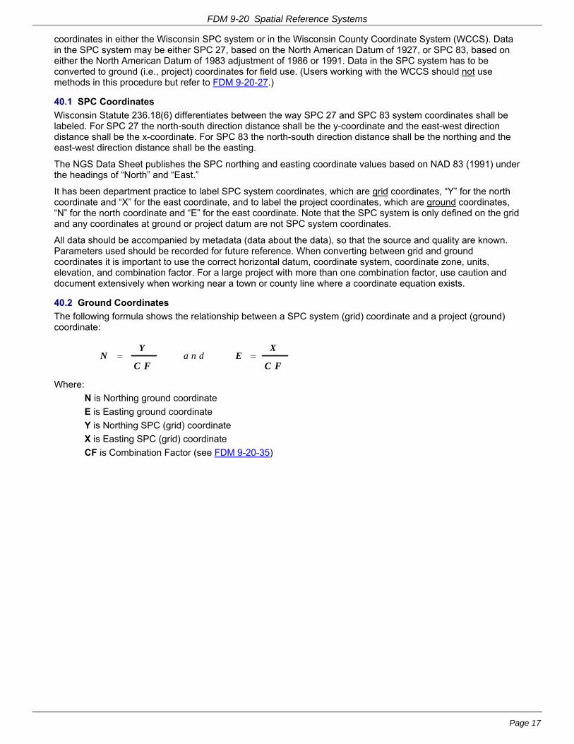
FDM 9-20 Spatial Reference Systems
Page 17
coordinates in either the Wisconsin SPC system or in the Wisconsin County Coordinate System (WCCS). Data in the SPC system may be either SPC 27, based on the North American Datum of 1927, or SPC 83, based on either the North American Datum of 1983 adjustment of 1986 or 1991. Data in the SPC system has to be converted to ground (i.e., project) coordinates for field use. (Users working with the WCCS should not use methods in this procedure but refer to FDM 9-20-27.)
40.1 SPC Coordinates
Wisconsin Statute 236.18(6) differentiates between the way SPC 27 and SPC 83 system coordinates shall be labeled. For SPC 27 the north-south direction distance shall be the y-coordinate and the east-west direction distance shall be the x-coordinate. For SPC 83 the north-south direction distance shall be the northing and the east-west direction distance shall be the easting.
The NGS Data Sheet publishes the SPC northing and easting coordinate values based on NAD 83 (1991) under the headings of “North” and “East.”
It has been department practice to label SPC system coordinates, which are grid coordinates, “Y” for the north coordinate and “X” for the east coordinate, and to label the project coordinates, which are ground coordinates, “N” for the north coordinate and “E” for the east coordinate. Note that the SPC system is only defined on the grid and any coordinates at ground or project datum are not SPC system coordinates.
All data should be accompanied by metadata (data about the data), so that the source and quality are known. Parameters used should be recorded for future reference. When converting between grid and ground coordinates it is important to use the correct horizontal datum, coordinate system, coordinate zone, units, elevation, and combination factor. For a large project with more than one combination factor, use caution and document extensively when working near a town or county line where a coordinate equation exists.
40.2 Ground Coordinates
The following formula shows the relationship between a SPC system (grid) coordinate and a project (ground) coordinate:
NY
C FE
X
C F a n d
Where:
N is Northing ground coordinate
E is Easting ground coordinate
Y is Northing SPC (grid) coordinate
X is Easting SPC (grid) coordinate
CF is Combination Factor (see FDM 9-20-35)

FDM 9-20 Attachment 5.1 Pattern of PLSS Townships & Ranges for Wisconsin
July 23, 2015 Attachment 5.1 Page 1

FDM 9-20 Attachment 5.2 Method of Numbering Sections
July 23, 2015 Attachment 5.2 Page 1
METHOD OF NUMBERING SECTIONS
6
5
4
3
2
1
7
8
9
10
11
12
18
17
16
15
14
13
19
20
21
22
23
24
30
29
28
27
26
25
31
32
33
34
35
36

FDM 9-20 Attachment 25.1 Map Projection
February 28, 2001 Attachment 25.1 Page 1

FDM 9-20 Attachment 25.2 Universal Transverse Mercator Coordinate System
February 28, 2001 Attachment 25.2 Page 1
Universal Transverse Mercator (UTM) Coordinate System
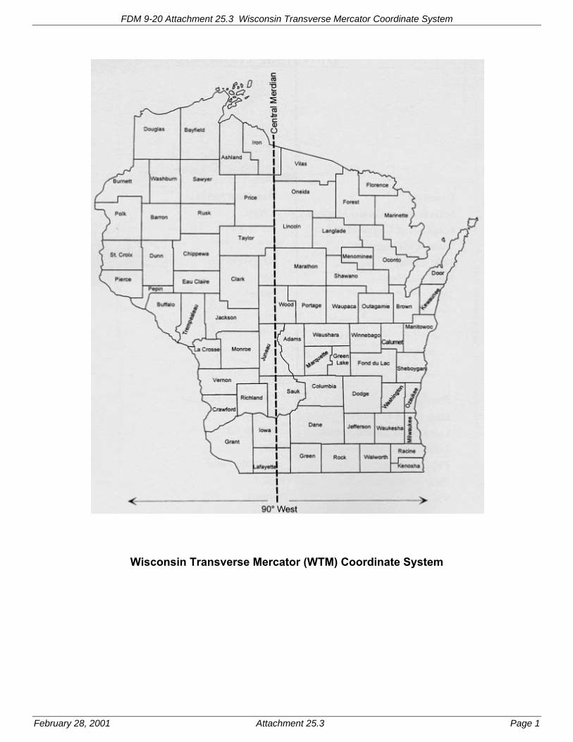
FDM 9-20 Attachment 25.3 Wisconsin Transverse Mercator Coordinate System
February 28, 2001 Attachment 25.3 Page 1
Wisconsin Transverse Mercator (WTM) Coordinate System

FDM 9-20 Attachment 26.1 Wisconsin State Plane Coordinate System
February 28, 2001 Attachment 26.1 Page 1
Wisconsin State Plane Coordinate (SPC) System

FDM 9-20 Attachment 27.1 Wisconsin County Coordinate System
February 28, 2001 Attachment 27.1 Page 1
Wisconsin County Coordinate System (WCCS) Note: Adjoining counties shown with a common tint share the same coordinate system parameters. Counties shaded the same as the background each have a separate coordinate system.

FDM 9-20 Attachment 27.2 Wisconsin County Coordinate System Zones
June 8, 2000 Attachment 27.2 Page 1
Wisconsin County Coordinate System Zones
Adams 9501 Ashland 9502 Barron 9503 Bayfield 9504 Brown 9505 Buffalo 9506 Burnett 9507 Calumet 9508 Chippewa 9509 Clark 9510 Columbia 9511 Crawford 9512 Dane 9513 Dodge 9514 Door 9515 Douglas 9516 Dunn 9517 Eau Claire 9518 Florence 9519 Fond du Lac 9520 Forest 9521 Grant 9522 Green 9523 Green Lake 9524 Iowa 9525 Iron 9526 Jackson 9527 Jefferson 9528 Juneau 9529 Kenosha 9530 Kewaunee 9531 La Crosse 9532 Lafayette 9533 Langlade 9534 Lincoln 9535 Manitowoc 9536 Marathon 9537 Marinette 9538 Marquette 9539 Menominee 9572 Milwaukee 9540 Monroe 9541 Oconto 9542 Oneida 9543 Outagamie 9544 Ozaukee 9545 Pepin 9546 Pierce 9547 Polk 9548 Portage 9549
Price 9550 Racine 9551 Richland 9552 Rock 9553 Rusk 9554 St. Croix 9555 Sauk 9556 Sawyer 9557 Shawano 9558 Sheboygan 9559 Taylor 9560 Trempealeau 9561 Vernon 9562 Vilas 9563 Walworth 9564 Washburn 9565 Washington 9566 Waukesha 9567 Waupaca 9568 Waushara 9569 Winnebago 9570 Wood 9571
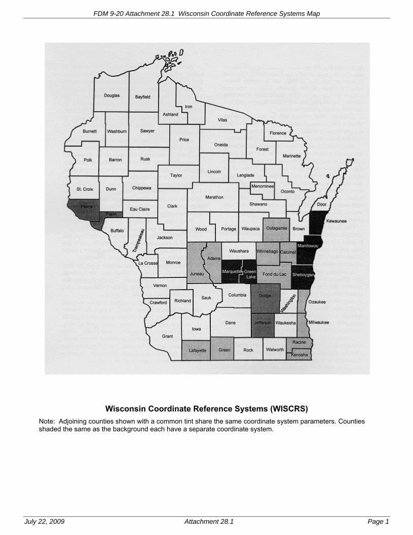
FDM 9-20 Attachment 28.1 Wisconsin Coordinate Reference Systems Map
July 22, 2009 Attachment 28.1 Page 1
Wisconsin Coordinate Reference Systems (WISCRS)
Note: Adjoining counties shown with a common tint share the same coordinate system parameters. Counties shaded the same as the background each have a separate coordinate system.

FDM 9-20 Attachment 28.2 Wisconsin Coordinate Reference Systems Zone Numbers
July 22, 2009 Attachment 28.2 Page 1
Wisconsin Coordinate Reference Systems (WISCRS)
Zone Numbers for Counties
Adams 9601 Outagamie 9644
Ashland 9602 Ozaukee 9645
Barron 9603 Pepin 9646
Bayfield 9604 Pierce 9647
Brown 9605 Polk 9648
Buffalo 9606 Portage 9649
Burnett 9607 Price 9650
Calumet 9608 Racine 9651
Chippewa 9609 Richland 9652
Clark 9610 Rock 9653
Columbia 9611 Rusk 9654
Crawford 9612 St. Croix 9655
Dane 9613 Sauk 9656
Dodge 9614 Sawyer 9657
Door 9615 Shawano 9658
Douglas 9616 Sheboygan 9659
Dunn 9617 Taylor 9660
Eau Claire 9618 Trempealeau 9661
Florence 9619 Vernon 9662
Fond du Lac 9620 Vilas 9663
Forest 9621 Walworth 9664
Grant 9622 Washburn 9665
Green 9623 Washington 9666
Green Lake 9624 Waukesha 9667
Iowa 9625 Waupaca 9668
Iron 9626 Waushara 9669
Jackson 9627 Winnebago 9670
Jefferson 9628 Wood 9671
Juneau 9629
Kenosha 9630
Kewaunee 9631
La Crosse 9632
Lafayette 9633
Langlade 9634
Lincoln 9635
Manitowoc 9636
Marathon 9637
Marinette 9638
Marquette 9639
Menominee 9672
Milwaukee 9640
Monroe 9641
Oconto 9642
Oneida 9643
Page 1
FDM 9-25-1 Perpetuation of Landmarks October 28, 1994
It is the policy and practice of the department to take all reasonable measures to perpetuate survey landmarks. The purpose of this procedure is to specify in more detail the responsibilities of the department in achieving a continuing program of perpetuation of landmarks. For the department's policy on perpetuation of landmarks refer to FDM 9-5-1.
The records for the State Commissioners of Public Lands contain copies of the original notes of the U. S. Public Land Surveys. Photostat copies of the original plat of a township and notes for specific section corners, quarter corners, etc., can be obtained by writing to the Department of Justice, Board of Commissioners of Public Lands, P. O. Box 8943, Madison, WI 53708-8943. Technical Services has a complete set of the photostat copies of these records.
It is not within the authority or responsibility of the department to establish the boundary between property owners abutting the highway; however, it is the practice of the department to avoid the destruction of any property corner monument. Therefore, the position of every monument that is found and that is likely to be disturbed by construction activities shall be perpetuated in accordance with the perpetuation of landmarks policy (see FDM 9-5-1).
1.1 Corners To Be Recovered And Perpetuated 1. When the proposed project involves only resurfacing of the existing pavement, all landmarks of a
survey of public record that have previously been perpetuated by a monument in the existing pavement surface shall be perpetuated in the new surface.
2. When the proposed project involves reconstruction within the existing right-of-way, all corners for which a survey of public record shows a landmark was placed and which lie within the construction limits of the project shall be recovered, and if found, shall be perpetuated.
3. On any project requiring the acquisition of right-of-way, in addition to the corners specified in the paragraphs above, the corners of the U. S. Public Land Survey at both ends of every section and one- quarter section line that runs along, upon, or across the right-of-way should be recovered and perpetuated. In some areas of the state where many of the U. S. Public Land Survey corners are "lost corners," as defined in the Manual of Surveying Instruction, 1973, professional judgment may dictate that recovery of every section line would be too costly. In such cases, sufficient corners shall be recovered and perpetuated so that every parcel of right-of-way to be acquired is tied to at least one monumented line of the section within which it lies.
4. Any lost corners that are established at WisDOT's expense shall be perpetuated.
1.2 Landmark Perpetuation 1.2.1 Before Surveys A thorough search of the records should be made to determine if landmarks of public record exist on the proposed project. County surveyors and city/village engineers should be asked to research their records and provide WisDOT with any information they have concerning landmarks within the project limits. The region should make a thorough search of the records in the region office.
1.2.2 During Surveys During the original survey, locate and record in the survey notes every corner required to be perpetuated. Record the exact location of every monument found that appears to be a landmark identifying a lot corner, even though it may not be perpetuated.
After the field search, if there is a reasonable doubt as to the evidence identifying any of the corners required to be perpetuated, a Registered Land Surveyor should supervise the recovery of the corner. The region may negotiate a special services contract (see Chapter 8) with a Registered Land Surveyor in full-time private practice (preferably the county surveyor) for recovering and perpetuating the required corners. In those counties where there is no county surveyor, and it appears desirable to have one appointed, the procedure outlined in Section 59.635(3), Wisconsin Statutes, may be followed.
To facilitate the excavation work necessary to recover evidence of landmarks and to minimize the cost of such
Wisconsin Department of Transportation Facilities Development Manual Chapter 9 Surveying and Mapping Section 25 Monumentation

Page 3
FDM 9-25-5 Control Monumentation August 15, 2019
excavation, the region may request the County Highway Commissioner to rent equipment and operators to the region. See FDM 8-5-1 for Short Form contract boilerplate language.
1.2.3 Prior to Construction See FDM 9-5-1
1.2.4 During Construction Refer to CMM 7-85 for monumentation practices and procedures during construction.
1.2.5 After Construction All USPLS landmarks and/or block corners that WisDOT deemed of interest will be restored to original location after construction and/or perpetuated with four or more witness monuments or offset markers. Monumented lot corners that are disturbed by WisDOT construction will be restored at the request of the property owners.
WisDOT will make a field survey of the landmark and witness monuments and provide a copy to the county. This will be done for informational purposes only. The note will state explicitly that this monument is not being certified as an actual corner, only that a certain type of landmark was found and is perpetuated by a monument or reference monuments.
Upon completion of construction, WisDOT will, if requested, reset an appropriate type of monument in the original location. WisDOT will file with the county/municipality the type of monument set. This will be done for informational purposes only. The notes will state that this monument is not being certified as an actual landmark, only that certain evidence of a landmark was found and that due to construction, it was necessary to remove and reset a landmark at the location.
Permanent monumentation of selected survey points is necessary to efficiently survey existing and future transportation improvement projects. FDM 9-25-10 describes the different types of survey monuments. This procedure describes engineering control monumentation and FDM 9-25-6 describes required right-of-way monumentation.
5.1 Horizontal Control Use a Type 1 or Type 2 monument to monument each primary horizontal control survey station for a transportation improvement project. A pair of stations monumented with Type 1 or Type 2 monuments shall be established at each end of the project (see FDM 9-35-1 for types of projects requiring horizontal control) and at intervals no greater than 2 to 3 miles throughout the project. Only one pair of stations is required to be monumented with Type 1 or Type 2 monuments for a project of less than 0.5 mile in length. The pairs of stations for primary project horizontal control are usually best established using Global Positioning System (GPS) methods.
Use a Type-2 or Type-3 monument to monument secondary horizontal control survey stations for a transportation improvement project.
Reference each horizontal control station (including any existing stations) to a minimum of three nearby geographical features with a distance measured to each feature to at least the nearest 0.5 foot. These distances are intended to help find the station, not to reestablish the station. Usually the road centerline will be one of the features. The station shall be described in a textual description detailing the general location, specific location with a distance and a direction relative to each of the features, and the type of monument. A location sketch for each station may be drawn in addition to the textual description.
5.2 Vertical Control Use a Type 1 monument or Type 2 chiseled-square monument to monument each primary vertical control survey station (i.e., a benchmark) for a transportation improvement project. Projects requiring vertical control shall have a pair of benchmarks monumented with Type 1 monuments or Type 2 chiseled-square monuments at each end of the project and at intervals no greater than 2 to 3 miles throughout the project. Only one pair of benchmarks is required to be monumented with Type 1 monuments or Type 2 chiseled-square monuments for a project of less than 0.5 mile in length.
Reference each benchmark (including existing benchmarks) to a minimum of three nearby geographical features with a distance measured to each feature to at least the nearest 0.5 foot. These distances are intended to help find the station. Usually the road centerline will be one of the features. When a benchmark is on a

Page 4
feature, the feature name should be included (e.g., a chiseled square on the north end of the east abutment of bridge B-12-123). The “station and out” method of locating a project benchmark may be used in lieu of measuring distances to features. The benchmark shall be described in a textual description detailing the general location, specific location with a distance and a direction relative to each of the features, and the type of monument. A location sketch for each benchmark may be drawn in addition to the textual description.
Existing benchmarks which appear to be in danger of being destroyed during construction shall be considered for preservation or relocation. If the benchmark is listed in the National Spatial Reference System1 maintained by the National Geodetic Survey (NGS), the NGS State Geodetic Advisor2 shall be contacted early in the design phase. If the monument will be destroyed by highway construction, an item under Landmark Reference Monuments may be included in the plan for setting a new monument and a general note should be included to describe such items as type of disk and special dimensions. Transferring of elevations should be done by a survey crew in accordance with instructions provided by the NGS Geodetic Advisor.
The region survey coordinator will be the primary point of contact to provide a survey disk to the contractor to be placed in a structure during construction. The disk shall be set horizontally (not vertically) in the top of the parapet in close proximity to the structure name plate per section 6.3.3.7 of Bridge Manual. A station name is generally not assigned to a disk set in a structure per this section. An elevation shall be transferred to the disk prior to the completion of the construction project. Contact the region survey coordinator for the appropriate region form(s) used to document the new elevation, location and other information. Each region office will determine the proper mechanism to maintain and disseminate this information. See Bridge Manual 6.3.3.7 for more information on structure benchmarks.
5.3 Three-Dimensional Control Three-dimensional control survey stations should be monumented to at least the minimum requirements listed above for Horizontal Control AND for Vertical Control. Three-dimensional control survey stations will usually be established using Global Positioning System (GPS) survey methods. When traditional methods have been used to extend horizontal control to a survey station AND spirit leveling has been used to determine an elevation of a benchmark, the monumentation should meet the requirements for a three-dimensional station.
5.4 Alignment Surveys A sufficient number of alignment points or horizontal control survey points shall be monumented to facilitate reestablishing the alignment. The points shall be monumented with a Type 1 monument either during or upon completion of construction. The monumented points may include PIs, POTs, PCs, PTs, or project horizontal control points. All monumented points shall be referenced to a minimum of three nearby geographical features with a distance measured to each feature to at least the nearest 0.5 foot. These distances are intended to help find the station, not to reestablish the station. Usually the road centerline will be one of the features. Enough points shall be monumented to define the bearing of each tangent with two points.
5.5 General Survey Disk Characteristics and Stamping
Survey disks that are to be set as part of a Wisconsin DOT transportation improvement project shall:
• Have a diameter of between 3 and 3-1/2”.
• Have a stem that is at least 2-3/4” long
• The top be domed rather than flat
• Disk shall be made from aluminum or bronze
Survey disks should be pre-stamped from the manufacturer with information and format shown below. All initial stamping from the manufacture shall be in capital letters. See Figure 5.1.
• A center dimple.
• On the upper, outer row of lettering: WIS. DEPT. OF TRANSPORTATION
• On the upper, next to outer row of lettering: SURVEY STATION
• On the lower, next to outer row of lettering: UNLAWFUL
• On the lower, outer row of lettering: TO DISTURB

Page 5
FDM 9-25-6 Right of Way Monumentation November 30, 2018
Figure 5.1. Sample Survey Disk
It is not necessary that every station disk have a station name, but in many cases, a station name makes it easier to facilitate communication regarding the station. The survey coordinator will determine station names and if it will be stamped on a disk at a later date.
Other monument types may not allow for the standard stamping as detailed above. The region survey coordinator will determine how best to place information on other types of monuments.
Right-of-way monuments shall be set in accordance with Department policy for all new right-of-way acquisitions in fee or by highway easement, and for all Permanent Limited Easements (PLE). See FDM 9-5-5 for more information on Right-of-Way Monumentation Policies and FDM 9-25-10 for more information regarding survey monuments. Requests for additional information about right-of-way monumentation should be directed to the Right-of-Way Plat Coordinator/Land Surveyor at 608-243-3397 or the Chief Surveying & Mapping Engineer at 608-246-7941.
6.1 Monument Location and Type A right-of-way monument shall be set:
- At every change in direction of a right-of-way line.- At the beginning and end of every curve.- At a maximum spacing between right-of-way monuments of approximately 0.25 mile (0.40 km) on
tangents and 500 feet (150 m) on curves.
A right-of-way monument usually will be a Type 2 monument; however, a more substantial Type 1 monument may be used in lieu of a Type 2 monument. See FDM 9-25-10 for characteristics of different monument types.
6.2 Right-of-Way Marker Post A right-of-way marker post shall be set near every right-of-way monument; except, the requirement to place a right-of-way marker post is waived when the post would generate aesthetic or safety concerns if set in a front lawn, decorative landscaped area, sidewalk, pathway, parking lot, or driveway.
A right-of-way marker post shall be set in the right-of-way with the back of the post along the right-of-way line. When the marker post is at a corner monument, the marker post shall be set along the longer of the two right-of- way lines.
The right-of-way marker post shall conform to the standard shown in the standard detail drawing (SDD) for Marker Post for Right-of-Way (see Chapter 16, SDD 15A1).
A right-of-way marker post shall be set: - 0.5 to 2 feet (0.15 to 0.6 m) from the monument.- With a R/W plaque on the front of the marker post facing the roadway.- With an informative plaque on the back of the marker post facing away from the roadway.
6.2.0.1 Installation Monuments shall be set in a timely manner within the limits of the region workload prior to or at the time of land transfer. Type 1 monuments and right-of-way marker posts shall be set by contract bid item unless stated on the

Page 6
plan to be set by others, or unless they are in place prior to the letting of the contract.
6.3 Coordinates The location of each right-of-way monument and each U.S. Public Land Survey System (PLSS) corner shall be identified on the right-of-way plat. When Type 1 monuments are used, the location of each Type 1 monument shall be provided to the county surveyor in addition to being identified on the right-of-way plat. Each PLSS corner shown shall have a Wisconsin County Coordinate System (WCCS) or Wisconsin Coordinate Reference Systems (WISCRS) coordinate value (see FDM 9-20-27). When the Wisconsin State Plane Coordinate System (SPCS) (see FDM 9-20-26) is used to control the transportation project, SPCS coordinates may be used in lieu of WCCS or WISCRS coordinates to record the right-of-way acquisition.
6.4 Positioning Requirements Each right-of-way monument (whether new or existing) shall:
- Be referenced to a minimum of two monumented PLSS corners.- Have its position determined to a minimum horizontal positional accuracy of one part in three thousand
(1:3,000) for a Type 2 monument or one part in ten thousand (1:10,000) for a Type 1 monument.
In addition to the above positioning requirements, one or more of the following methods may be used to identify the location and/or boundary of the right-of-way acquisition. Whichever method is used, it shall be followed completely. When more than one method is used, each method shall be followed completely.
- When Type 1 monuments are set on the right-of-way line, they shall be set in pairs, one each at twointervisible right-of-way points. The distance between the monuments in a pair shall be a minimum of1000 feet (305 m). Reasonable care should be used in selecting the location of the right-of-waymonument pairs so they will continue to be intervisible for some years after the transportationimprovement project has been completed. A pair of monuments shall be set approximately every mile(1.6 km).
- When Type 1 monuments are set on a survey reference line to provide monumentation of the highway(usually on the centerline), then the right-of-way monuments may be referenced to the surveyreference line. Points monumented on the reference line may include PIs or selected POTs. PCs orPTs maybe used when PIs are outside of the right-of-way, on shoulders, or in other unusablelocations. Enough points shall be monumented on the reference line to define the bearing of eachtangent with two points.
- When an existing geodetic control station monument (e.g., Wisconsin High Accuracy ReferenceNetwork [HARN] station, User Densification Network [UDN] station, or Wisconsin HeightModernization Program [HMP] station) is used to determine the position of a right-of-way monument,the geodetic control station designation, the reference datum/adjustment, and the station WCCS,WISCRS, or SPCS coordinates should be identified in the right-of-way documentation.
6.5 Documentation Each region shall develop and maintain documentation showing the placement of right-of-way monuments and supporting monuments. Information shown on the plat shall be referenced and not duplicated in the region documentation. The documentation shall include for each right-of-way monument and each supporting monument:
- A description of the size, shape, and material of the monument.- The name (designation) and other information stamped on the monument marker.- The depth of the top of the monument below ground or the height the monument projects above
ground.- The condition of the monument.- The geographic or rectangular coordinates of the monument.- The coordinates of the beginning point(s) of the survey.- The reference geodetic datum/adjustment of the beginning point(s) of the survey.- The source of information for the beginning point(s) coordinates.
The documentation should include the dates and methods of fieldwork, computations, and other information, which could be useful for future work.
6.6 Minor Acquisition Right-of-way monuments for a minor right-of-way acquisition of less than $1000 shall meet all of the above requirements except that the right-of-way monuments need to be referenced to only one monumented PLSS

Page 7
FDM 9-25-10 Engineering Survey Monuments August 15, 2019
corner and have a basis of bearing. The “basis of bearing” requirement may be met by each right-of-way monument having a WCCS or WISCRS coordinate (see FDM 9-20-27), or by referencing two monumented PLSS corners. When the Wisconsin SPCS (see FDM 9-20-26) is used to control the transportation project, SPCS coordinates may be used in lieu of WCCS or WISCRS coordinates.
The purpose of a survey monument is to provide a recoverable, stable, and usually permanent reference point for future surveys. Engineering survey monuments used for control of a transportation improvement project or to identify a property boundary may be constructed to less stringent specifications than geodetic survey monuments which are part of a statewide geodetic control network.
Engineering survey monuments have traditionally been referred to within the department as Type 1, Type 2, or Type 3 monuments. Higher-order monuments may be used in lieu of a lower-order monument. For example, a geodetic survey monument may be used when a Type 1 monument is required; a geodetic survey monument or a Type 1 monument may be used when a Type 2 monument is required.
Type 1 and Type 2 monuments are considered as permanent monuments and therefore should have a permanent description of their location filed with the appropriate document. For example as a minimum, the location of a monument used for project control should be identified on or with a project plan; the location of a property monument should be identified on a plat.
Monuments are the foundation for survey control. It is critical that a monument be placed in a location that insures the permanency and stability required. The environment of the monument always needs to be evaluated prior to setting a monument; e.g., will the kind of monument selected be sufficiently stable in the soil conditions encountered? 10.1 Type 1 Monument A Type 1 monument shall be constructed to be permanent, stable, and identifiable. It should be constructed of materials that can be expected to last for at least 50 years and be placed in a location that is not expected to be in the way of construction or maintenance equipment. If equipment travel is anticipated in the area of the monument, the top of the monument should be recessed 1 to 3 inches below ground level. A Type 1 monument should be sufficiently stable to serve its intended purpose with only minimum motion in a horizontal or vertical direction.
A metal marker3 shall be firmly attached to the top of the monument base. The stem of the survey disk is usually pushed into fresh concrete when cast-in-place or precast concrete monuments are used; however, cured concrete may be drilled and the stem of the survey disk anchored in the drill hole with epoxy resin. The survey disk or cap should include an inscription (a cast or machine-imprinted legend or logo) of the establishing agency and space for the survey station (bench mark or corner) designation (name) to be stamped on the survey disk or cap.
Within the category of Type 1 monuments, some monuments will exhibit better stability, endurance, availability, and economics than others. Generally, the order in which they are listed below is the order of monument preference for engineering control and right-of-way monumentation. A rock, permanent structure, or cast-in- place concrete monument should be the selected Type 1 monument unless another Type 1 monument is specified in the contract or approved by the project manager.
The following listed monuments are a Type 1 monument (see Attachment 10.1).
10.1.1 Rock Monument A rock monument is a survey disk firmly set with epoxy resin into a drill hole in a rock outcrop. Only sound bedrock should be selected as a location for setting the survey disk. This monument is suitable for use on a survey requiring a monument with horizontal, vertical, or three-dimensional control.
10.1.2 Permanent Structure Monument A permanent structure monument is a survey disk firmly attached to a horizontal surface of a structure, wingwall or building foundation that is stable and permanent in nature. A survey disk should NOT be attached to anything that is subject to movement. This type of monument is suitable for use with horizontal, vertical, or three-dimensional control. An existing survey disk that was set vertically and has an existing elevation may be used for vertical control. However, when a new survey disk is to be set on a structure it shall be set horizontally (not vertically).
10.1.3 Cast-In-Place Concrete Monument

Page 8
A cast-in-place concrete monument is a cast-in-place concrete post with a survey disk set into the top of the post. The post should have embedded steel rods for easier magnetic detection and strength. See SDD 16A1, "Landmark Reference Monuments" (Type A) for shape and minimum dimensions of monument and survey disk. This monument is suitable for use on a survey requiring a monument with horizontal, vertical, or three- dimensional control.
10.1.4 Precast Concrete Monument A precast concrete monument is a precast concrete post with a survey disk set into the top of the post. The post should be in the shape of a truncated prism with the lower end larger than the upper end for resisting frost action. The post should have embedded steel rods for easier magnetic detection and strength. See SDD 16A1, "Landmark Reference Monuments" (Type A) for minimum dimensions of monument and survey disk. This monument is suitable for use on a survey requiring a monument with horizontal, vertical, or three-dimensional control.
10.1.5 Boulder Monument A boulder monument is a survey disk set into a drill hole in a large boulder and firmly attached with epoxy resin. The stability of the boulder must be evaluated as even a very large surface boulder is subject to movement by erosion and by frost heave if it does not extend below the frost depth. This monument is suitable for use on a survey requiring a monument with horizontal control. It may be used with caution for vertical or three- dimensional control.
3 Called a “survey disk” when the stem of the disk is anchored in concrete or rock, or a “survey cap” when attached to the end of a pipe or rod.
10.1.6 Iron Pipe Monument An iron pipe monument is a 2- or 3-inch inside diameter iron or steel pipe4 weighing not less than 3.65 pounds per lineal foot and at least 30 inches in length with a survey cap firmly affixed to the top of the pipe. This monument is suitable for use on a survey requiring a monument with horizontal control.
10.1.7 Metal Monument A metal monument is a metal post or pipe with a survey cap affixed to the top and has magnetized material top and bottom for easier detection. See SDD 16A1, "Landmark Reference Monuments" (Types C and D) for details. This is a special purpose monument, normally used where other Type 1 monuments would not be as stable (e.g., in a sandy soil or marshy area) or not be economical (e.g., in an area not accessible by vehicle to transport concrete to the site). The drive-in monument (Type C) is not intended for use in cohesive (clayey) soil. When the drive-in monument is used in a marshy area, the pipe should be as long as necessary to be stable but be no less than 60 inches in length. This monument is suitable for use on a survey requiring a monument with horizontal control.
10.2 Type 2 Monument A Type 2 monument shall be stable and constructed to be permanent. It should be constructed of materials that can be expected to last for at least 25 years. This type monument is often used to monument property boundaries. Recessing the monument below ground level will likely prolong its life by keeping it out of the way of maintenance equipment. A nonmetallic (plastic) or metal cap with a machine imprinted legend (logo) is usually used to identify the establishing agency.
The following listed monuments are a Type 2 monument (see Attachment 10.2).
10.2.1 Iron Pipe Monument An iron pipe monument is a 1-inch or larger, inside diameter iron or steel pipe weighing not less than 1.13 pounds per lineal foot and at least 24 inches long with a cap. This monument is suitable for use on a survey requiring a monument with horizontal control.
10.2.2 Metal Rod Monument A metal rod monument is a ¾-inch or larger-diameter steel rod (a number 6, or larger, reinforcing bar) at least 24 inches long with a nonmetallic (plastic) cap. This monument is suitable for use on a survey requiring a monument with horizontal control.
10.2.3 Extendable Metal Rod Monument An extendable metal rod (drivable anchored rod) monument is a ¾-inch or larger- diameter metal rod at least 24 inches long with a fluted cast point and magnetized metal tap-on cap. This monument is useful in unstable or

Page 9
very sandy soil. This monument is suitable for use on a survey requiring a monument with horizontal control.
10.2.4 Metal Pipe Monument A metal pipe monument is a 1-inch or larger-diameter nonmagnetic, light-weight, metal pipe at least 24 inches long with a fluted cast point and magnetized metal tap-on cap. This is a special purpose monument, normally used where other monuments would not be as stable (e.g., in a sandy soil or marshy area). This monument is not intended for use in cohesive (clayey) soil. When this monument is used in a marshy area, the pipe length should be as long as necessary to be stable but be no less than 60 inches in length. This monument is suitable for use on a survey requiring a monument with horizontal control.
10.2.5 Chiseled-Cross Monument A chiseled-cross monument is a 2-inch by 2-inch or larger, chiseled, or sawed, cross (“+”) at least ¼ inch deep in a concrete structure or foundation. This monument is suitable for use on a survey requiring a monument with horizontal control. This monument shall not be used for vertical or three-dimensional control.
10.2.6 Chiseled-Square Monument A chiseled-square monument is a 2-inch by 2-inch or larger, chiseled or sawed square (“ ”) outline at least ¼ inch deep on a horizontal surface of a concrete abutment or foundation for a large structure or building. The elevation point is the undisturbed horizontal surface of the concrete inscribed by the square outline. Avoid using a structure exhibiting previous vertical movement with deformation cracks or by not being level. This monument is suitable for use on a survey requiring a monument with vertical control. This monument shall not be used for horizontal or three-dimensional control because the shape of the monument does not have a finitely defined
4 The department normally uses a 2-inch pipe.
horizontal point.
10.3 Type 3 Monument A Type 3 monument is a temporary survey monument. A temporary survey monument is intended to be used only for a single project and often only for a single season. Even a temporary monument should be unique so as not be confused with other similar nearby monuments and be stable enough to not move significantly during its expected life. The stability of the monument will be no better than the stability of the feature; therefore, the stability of the feature needs to be evaluated prior to using the feature for a monument.
Some Type 3 monuments may be needed for multiple seasons; therefore, the feature supporting the monument needs to be evaluated to assure selection of the most stable feature in the area. Examples: Asphalt pavement may be a stable feature at one location but an unstable feature at another location or different time of year. A culvert may be a stable feature at one location but at another location a culvert may be an unstable feature, or a culvert may be unstable depending upon the time of year. A culvert with water flowing year around and placed many feet below the roadway will usually be more stable than a nearby culvert flowing water only after a storm and placed only a foot below the roadway.
A monument intended to be used for multiple projects or for multiple years normally should be a permanent Type 1 or Type 2 monument. A Type 3 monument may be used to monument engineering control (not property boundaries) expected to be used in multiple years if the Type 3 monument meets all of the following:
- The monument is expected to be sufficiently durable to last for the entire project.- The monument is stable enough to not move significantly for the entire project.- The monument is identifiable from any other similar monuments in the area.- The monument is described with at least three references (ties) for verification.- The monument description is filed with the project control data.- The monument is supplementary to other nearby permanent monuments.- The monument is approved by the region survey unit coordinator to be used in lieu of a higher-order
monument.
The following listed monuments are a Type 3 monument (see Attachment 10.3).
10.3.1 Metal Rod Monument A metal rod monument is a 5/8-inch or larger-diameter steel rod (a number 5, or larger, reinforcing bar) at least 24 inches long with, or without, a nonmetallic (plastic) cap. In loose soil (e.g., clean fine sand, soft wet organic soil, or poorly compacted fill material), the length of the rod should be increased to improve horizontal stability.
Page 10
This monument is suitable for use on a survey requiring a monument with horizontal control.
10.3.2 Masonry Nail Monument A masonry nail monument (often called a PK™ nail or MagNail™ monument) is a nail usually driven vertically into a dense massive feature such as asphalt pavement, concrete pavement, or a concrete structure. For concrete, the nail will be driven at a joint, crack, or drill hole. This monument may be suitable for use on a survey requiring a monument with horizontal, vertical, or three-dimensional control. When placed in a feature that is not horizontal, this monument may not be suitable for a survey requiring a monument with three-dimensional control.
10.3.3 Railroad Spike Monument A railroad spike monument is a railroad spike driven vertically into a dense massive feature such as asphalt pavement or horizontally into a pole to less than full length. This monument is suitable for use on a survey requiring a monument with horizontal control when the spike is driven vertically and a punch mark is placed on the head of the spike. It is suitable for vertical control when driven vertically into pavement or other massive stable feature, or driven horizontally into the side of a large tree or pole. It is suitable for three-dimensional control when driven vertically and the punch mark is at the high point of the spike.
10.3.4 Chiseled-Cross Monument A chiseled-cross monument is a chiseled, or sawed, cross (“+”) in concrete pavement, a concrete structure, or concrete foundation. This monument is suitable for use on a survey requiring a monument with horizontal control. This monument shall not be used for vertical or three-dimensional control.
10.3.5 Sawed-Cross Monument A sawed-cross monument is a sawed cross (“+”) in a metal surface; e.g., in a corrugated metal pipe culvert or rim bolt on a water hydrant. The cross may be stamped on a bolt head with a cold chisel. This monument issuitable for use on a survey requiring a monument with horizontal control. It is suitable for use on a survey requiring a monument with vertical or three-dimensional control if the cross (“+”) is at the high point of the metal surface.
10.3.6 Chiseled-Square Monument A chiseled-square monument is a chiseled or sawed square (“ ”) outline normally on a horizontal surface of concrete pavement, concrete structure, or concrete foundation. The elevation point is the high point of the undisturbed surface of the concrete inscribed by the square outline. If placed on a curved surface such as a concrete culvert pipe, the high point of the curve must be at the center of the square. A chiseled-square monument shall not be placed on a sloping surface. This monument is suitable for use on a survey requiring a monument with vertical control. This monument shall not be used for horizontal or three-dimensional control because the shape of the monument does not have a finitely defined horizontal point.
A Type 3 monument shall not be used when a permanent monument is required.
10.4 Type 4 Monument A Type 4 monument is a temporary survey monument and should be used only when requiring use of a Type 3 (or higher order) monument would cause unreasonable delay to the surveying operation. Any object may serve as a Type 4 monument providing the object meets all of the following:
- Be unique so as not be confused with other similar nearby objects.- Be sufficiently strong to support a survey rod or staff.- Be stable enough to not move significantly during its expected life.- Have a definite high point when used as a vertical control monument.- Have a defined “center” point when used as a horizontal control monument.
A Type 4 monument normally serves only a low-order, short-term purpose for a single project, a single season, and usually only a single survey crew. The following listed monuments are examples of a Type 4 monument.
- Nail in a tree, pole, structure, or railroad tie.- Hardwood hub.- Existing railroad spike in a railroad tie.- Existing bolt or steel bar protruding from a structure.- Corner of a building.- Edge or corner of pavement.

Page 11
- Fire hydrant.
The following listed features are examples of features that do not meet the minimum requirements for a Type 4 monument.
- Top nut of a fire hydrant.- A large aggregate in asphalt pavement.- Wooden or steel post in a fence line.- Boulder or chunk of concrete on the surface of the ground.- An object which moves when bumped, stepped on, leaned against, or touched by a human or animal.- An object which floats on water, or may float when water raises.- An object which “floats” by design such as the expansion/contraction span of a structure.
A Type 4 monument shall not be used when a permanent monument is required.
LIST OF ATTACHMENTS Attachment 10.1 Type 1 Monuments
Attachment 10.2 Type 2 Monuments
Attachment 10.3 Type 3 Monuments

FDM 9-25 Attachment 10.1 Type 1 Monuments
December 13, 2006 Attachment 10.1 Page 1
TYPE 1 MONUMENTS
Monument*
Horizontal Stability**
Vertical
Stability** Endurance Available at
needed Location
Use in Soil Type
Effort to Set Monument
Use for Control ***
Rock Excellent Excellent Very good Very seldom Sound Bedrock
Medium H, V, 3. B
Permanent Structure
Very good to poor ****
Very good to poor ****
Very good
Seldom
Not
applicable
Medium
H, V, 3. B
Cast-in-Place
Concrete
Good
Good to
poor
Good
Usually can be placed
where needed
All except
marsh
Large
H, V, 3. B
Precast concrete
Good to
poor
Good to
poor
Good
Usually can be placed
where needed
All except bedrock
and marsh
Large
H, V, 3. B
Boulder
Good to
poor
Poor
Good to poor
Very seldom
Only
granular
Medium
H, V(ST), 3(ST), B
Iron pipe
Good to
poor
Poor
Good to poor
Usually can be placed
where needed
Most
Medium
H, B
Metal
Good to
poor
Poor
Poor
Usually can be placed
where needed
Fine
granular and marsh
Medium
H, B
* See text for description of monuments. ** The stability of the monument and the surrounding area should always be evaluated by the surveyor before setting or using a monument. *** H=Horizontal Control, V-Vertical Control,3=Three dimensional control, B=Boundary Control, (ST)=See Text **** The stability of the monument depends upon the type and design of the structure. The foundation of a large structure is usually stable. A retaining wall is usually not stable.

FDM 9-25 Attachment 10.2 Type 2 Monuments
December 13, 2006 Attachment 10.2 Page 1
TYPE 2 MONUMENTS
Monument*
Horizontal
Stability**
Vertical
Stability**
Endurance
Available at needed
Location
Use in Soil Type
Effort to set Monument
Use for
Control***
Iron Pipe Good to poor
Poor Good to poor Usually can be placed
where needed
Most Small H, B
Metal Rod
Good to
poor
Poor
Good to poor
Usually can be placed
where needed
Most
Small
H, B
Extendable Metal Rod
Good to
poor
Poor
Good to poor
Usually can be placed
where needed
Fine
granular
Small
H, B
Metal Pipe
Good to
poor
Poor
Good to poor
Usually can be placed
where needed
Fine
granular and marsh
Small
H, B
Chiseled
Cross
Very good
Not
Applicable
Good
Very seldom
Not
applicable
Small
H, B
Chiseled Square
Not
applicable
Good
Good
Seldom
Not
applicable
Small
V(ST)
* See text for description of monuments. ** The stability of the monument and the surrounding area should always be evaluated by the surveyor before setting or using a monument. *** H=Horizontal Control, V-Vertical Control, B=Boundary Control, (ST)=See Text

FDM 9-25 Attachment 10.3 Type 3 Monuments
December 13, 2006 Attachment 10.3 Page 1
TYPE 3 MONUMENTS
Monument*
Horizontal Stability**
Vertical Stability**
Endurance
Available at needed
Location
Use in Soil Type
Effort to set Monument
Use
Control***
Metal Rod Good to poor Very Poor Good Usually can be placed where
needed
Most Small H
Masonry
Nail
Usually very
good
Very good to poor
Very good to
poor
Usually anywhere in
asphalt
Not applicable
Small
H, V, 3
Railroad
Spike
Very good to
poor
Very good to poor
Very good to
poor
Usually can be placed where
needed
Not applicable
Small
H, V, 3(ST)
Chiseled-
Cross
Very good
Not applicable
Good
Seldom
Not applicable
Small
H
Sawed-Cross
Very good
Good to poor
Good to poor
Seldom
Not applicable
Small
H, V(ST), 3(ST)
Chiseled-Square
Not applicable
Good
Good
Seldom
Not applicable
Small
V
* See text for description of monuments. ** The stability of the monument and the surrounding area should always be evaluated by the surveyor before setting or using a monument. *** H=Horizontal Control, V-Vertical Control,3=Three dimensional control, (ST)=See Text

Page 1
Facilities Development Manual Wisconsin Department of Transportation Chapter 9 Surveying and Mapping Section 30 Real Time Kinematic (RTK) Surveys
FDM 9-30-1 Introduction March 31, 2017
1.1 Overview
This section attempts to provide practical procedures and methods for using Real Time Kinematic (RTK) Global Navigation Satellite System (GNSS) to obtain consistent results for surveys performed by and for the Wisconsin Department of Transportation.
The terms ‘GPS’ (Global Positioning System) and ‘GNSS’ (Global Navigation Satellite System) are often used interchangeably, but each of these terms has its own unique meaning. GNSS is an all-inclusive term used to describe a satellite navigation system from any country or region, while GPS refers specifically to the NAVSTAR satellite navigation system of the United States run by the Department of Defense. The most common GNSS systems are GPS (United States), GLONASS (Russia), Galileo (European Union), BeiDou (China) and QZSS (Japan). In the past, ‘GPS’ was synonymous with any form of satellite based positioning because, for a period of time, the United States GPS system was the only GNSS system available for civilian surveying applications. This section will use the term GNSS rather than GPS.
RTK GNSS is a very good general observation tool for determining survey coordinates (horizontal and vertical) of a point. Some types of applications such as pavement matches and bridge decks require a more specific tool (e.g. total station) that RTK GNSS procedures should not be used for.
Stated accuracies in this section are achievable by using proper survey techniques described in the following pages which are based on recommendations and information from the following publications: National Geodetic Survey (NGS) Manual “User Guidelines for Single Base Real Time GNSS Positioning” (W. E. Henning, April, 2014), ‘Geodesy for the Layman’ (R. K. Burkard July, 1985); manuals from state agencies and workshops, webinars and seminars offered by NGS and other professional organizations. When establishing positional data on geodetic survey monuments, redundant observations taken over a period of time utilizing different satellite geometries are critical to the success for the survey to achieve its desired accuracy. Due to the variables involved with RTK GNSS satellite surveying, it is impossible to guarantee that every RTK observation will be within a given range of any previous observation.
The following guidelines are written to aid the user in obtaining the desired accuracy for their survey. No set of specifications can account for every scenario that a user may encounter at a job site. Satellite signal obstructions, GNSS satellite constellation and health, cellular reception, radio interference, equipment calibration and a myriad of other factors make every GNSS observation unique. These standards assume that the user has practical knowledge conducting RTK surveys and has a good attention to detail. A knowledgeable user will also have the ability to adapt these guidelines to local conditions, if required, to produce an accurate survey. Typical adaptions to these guidelines might involve extra observation times or sessions based on site conditions, observation statistics and/or satellite geometry. The user who has an understanding of the many variables involved in RTK GNSS observations will have better success in obtaining consistent results.
RTK GNSS surveying techniques yield a three-dimensional survey result made up of a horizontal and vertical component. The horizontal component is based on a mathematically derived ellipsoid that is designed and manipulated to represent the shape of an area of concentration. Briefly, RTK GNSS surveys collect latitude and longitude data based on an ellipsoid (currently GRS 80). These latitude and longitude values are converted to a two-dimensional coordinate system using the mathematically derived coordinate system parameters that are created when the coordinate system is developed.
The vertical component also uses the ellipsoid in determining an elevation. During GNSS observations, the GNSS receiver measures how high above the mathematical ellipsoid the survey monument is. Using a geoid model, an elevation is determined based on the amount of separation that has been determined at that exact spot between the ellipsoid and the earth’s surface (geoid separation) at the survey location. The amount of geoid separation is not consistent across the state to provide accurate survey elevations. Therefore, geoid models are produced by the National Geodetic Survey to better define the amount of geoid separation across the county. Geoid models are created based on thousands of miles of leveling that has been performed to determine precise elevations for stations combined with GNSS observations of the same stations to determine the geoid separation at these stations. This data is then used to create models that allow users to predict elevations based on ellipsoidal heights at a particular location. Geoid models are constantly being refined based on additional leveling and GNSS observations that are being performed. Providing leveled elevations and GNSS observations for refinement of geoid models is one of the primary functions of the Wisconsin Height

FDM 9-30 Real Time Kinematic (RTK) Surveys
Page 2
Modernization Program. In areas of sparse leveling and GNSS observations, geoid models will not yield an elevation that is as accurate as areas where more activity has taken place.
Horizontal positions are determined using rigorous mathematical procedures and vertical values are determined by non-mathematical modeling techniques. This is why vertical values are more difficult to determine accurately than horizontal positions. Strategies to provide accurate vertical values in difficult areas include: site calibration techniques, additional observation sets, longer observation times, augment GNSS observation with leveling or total station trig leveling, or a combination of these methods.
Again, repeated/redundant observations are critically important when establishing positions using RTK GNSS techniques.
If the user feels that any additional procedures or specifications should be included or discussed, please send your suggestions to [email protected], call 1-866-568-2852 or write;
WisDOT Office of Surveying & Mapping
3502 Kinsman Blvd
Madison, WI 53704-2549
These specifications will be reviewed on a periodic basis, and updated to reflect subsequent improvements in technology.
FDM 9-30-5 RTK Application Categories and Their Uses March 31, 2017
Engineering control application refers to the establishment of supplemental control stations in the project area. This type of positioning is used in areas where spacing of control stations from the Wisconsin Height Modernization Project (HMP), a county User Densification Network (UDN) or other network of control stations cannot sustain RTK survey methods. Stations established using engineering control standards typically are permanent or semi-permanent monuments that will be used as control for future work and maintain a stable position beyond the life of the project.
Project control application involves determining geodetic control positions for monuments that are generally a part of a transportation improvement project. Monuments set for a project are generally less stable than engineering control applications and are expected to hold their positions only for the life of a project. Typically these monuments are wooden stakes, PK nails, rebar with caps or chiseled shapes which are used as targets and or control for geospatial projects. Other project control applications would include positional determination of United State Public Land Corners, right-of-way monuments, any monument that depicts property interests (easement, property pin) or any other similar feature.
General (Topo) Position application is also commonly called a ‘topo shot’. They are a one-time observation of items or features to determine their location and or elevation or are a collection of observations used for topographic mapping purposes. Typically, features collected for this application do not lend themselves to repeat observations and likely will not have the accuracy that Engineering and Project Control Applications will have due to the lack of repeated/redundant observations. Examples of items collected using the General (Topo) Position application include, but are not limited to feature location, mapchecks, collecting or augmenting existing surface data, and control checks. Observations using General (Topo) Positioning applications can be used to check existing control values, but should never be used to establish or update control station horizontal coordinates or elevations.
The General (Topo) Positioning application does not have the benefit of redundant observations nor an internal network adjustment to help assure an accurate position for every observation. The user should be aware that accuracy at any one observation may be relatively elusive when compared to the Engineering and Project Control applications detailed in this section and other GNSS methods. These concepts are also further discussed in FDM 9-30-15 - Guideline 1.
Recovered benchmarks or monuments of older or unknown coordinates should be observed. If the user wishes to provide a position and elevation to place the monument in a GIS-type mapping application, the monument needs only to be observed to a General (Topo) Positioning specification. If the user wishes to update the horizontal coordinates or elevation values for future use, the monument should be observed to Engineering Control specifications.
FDM 9-30-10 General Scheme of RTK Survey Data Collection March 31, 2017
All application categories described in this section have requirements for individual observations based on the expected accuracy of the survey. The Engineering Control and Project Control applications also require repeated sets (groups) of GNSS RTK observations. Every observation within a set and every set of

FDM 9-30 Real Time Kinematic (RTK) Surveys
Page 3
observations have its own specifications that must be achieved to be considered successful. For repeated observations of the same monument, the user should rotate the rod after every observation to reduce systematic errors with the rover pole.
Observations that are done to General (Topo) Positioning standards consist of a single observation which must meet observation standards specific to that application. General (Topo) Positioning application does not require repeated observations nor observation sets.
These specifications assume that the user is using dual frequency receivers. The use of GLONASS and/or other GNSS satellite systems is not required, but highly recommended.
FDM 9-30-15 RTK Surveying Guidelines March 31, 2017
15.1 Table of RTK Surveying Guidelines
The following is a table of RTK surveying guidelines.
Table 15.1 Table of RTK Surveying Guidelines
Application
Guideline Engineering Control Project Control General (Topo)
Positioning
1. Desired Accuracy (95% Confidence Interval)
A. Horizontal
B. Vertical
0.05’ (1.5 cm)
0.066’ (2.0 cm)
0.05’ (1.5 cm)
0.082’ (2.5 cm)
0.066’ (2.0 cm)
0.18’ (5.5 cm)
2. Initialize rover receiver in area where at least three quadrants have no obstructions 15 degrees above the horizon and maintain initialization until point is observed.
YES
Do not initialize on a survey station
YES
Do not initialize on a survey station
YES
Do not initialize on a survey station
3. Initialization of Rover
A. Monitor observation statistics (PDOP, RMS, etc.) to ensure good initialization.
B. Maximum general RMS at initialization.
YES
0.07 feet
YES
0.07 feet
YES
0.12 feet
4. Maximum distance Between Base Station And Rover (Base/Rover Operation only)
5 miles 5 miles 5-1/2 miles
5. Obstructions
Unless noted, Guideline 5 applies to both GNSS rover units and base station setups (if used).
Significant obstructions will require longer observation times or additional observation set(s) to achieve desired application accuracy.
Obstructions projecting below the elevation mask set for the base and/or rover (Guideline 13) can be ignored.
New control points being established for Engineering and Project Control applications should be located in a spot with as few obstructions as possible.
The Southern three quarters of the sky should be clear above 15 degrees.
It is important that there are as few obstructions as practical, but obstructions up to 30 degrees may exist north of the station.
The Southern three quarters of the sky should be clear above 25 degrees.
Obstructions up to 40 degrees may exist north of the station attempting to limit blockage to one portion of the sky.
Base stations. Obstructions for base stations for this application shall be the same as the Project Control application.
Rover Units- See guideline 6 for discussion on rover operation in areas of poor GNSS signal reception.

FDM 9-30 Real Time Kinematic (RTK) Surveys
Page 4
6. Fixed or Float GNSS solution Fixed Fixed Fixed
7. Check shots of known control stations.
7A. Minimum number of published/known control points used as checks prior to beginning of survey data collection.
7B. Check into known control survey stations before and after every survey session.
7C. Check into known control stations during survey session.
1 Horizontal
2 Vertical
Required
Recommended
1 Horizontal
1 Vertical
Required
Recommended
1 Horizontal
1 Vertical
Required
Recommended
8. Check shot- maximum difference from published/known control station value which should be achieved before survey begins.
0.08’ horizontal.
0.10’ vertical
0.08’ horizontal.
0.12’ vertical
0.10’ horizontal.
0.15’ vertical
9. Minimum number of different control points used to set base station on when using base/rover system.
2 Horizontal
2 Vertical
2 Horizontal
2 Vertical. Not Applicable
10. Maximum Positional Dilution of Precision (PDOP) at the rover and base station (if used)
4.5 5.0 6.0
11. Collection interval (sec) 1 1 1
12. Minimum number of satellites tracked simultaneously and continuously during entire observation
7 6 6
13. Minimum Satellite Elevation Mask (zero is horizon and 90 is vertical)
15 degrees 15 degrees 15 degrees
14. Minimum number of observation sets per station.
3 2 1
15. Minimum number of observations within each observation set, rotating the rover pole after each observation
4 4 1
16. Minimum cumulative epochs (time) of observations per observation set for each station.
120
Approximately 2 min. (e.g. 4 observations of 30 epochs or 6 of
20 epochs)
120
Approximately 2 min. (e.g. 4 observations of 30 epochs or 6 of
20 epochs)
6
Approximately 6 sec
17. Break initialization between observation sets? Yes Yes Not Applicable
18. Ideal time interval between observation sets 4 Hours 4 Hours Not Applicable
19. Absolute minimum time between observation sets of the same station. Note that repeat observations shall not be 11 to 13 or 23 to 25 hours after previous set.
2-1/2 Hours (150 Minutes)
2 Hours
(120 Minutes) Not Applicable
20. Site Calibrations
20A. One Point Calibration
A1. Minimum number of appropriate control stations to be used for GNSS site calibration.
Note that a vertical calibration requires only vertical control stations, horizontal calibration requires only horizontal control stations and a total calibration requires appropriate number of horizontal and vertical control stations.
Two, one for calibration, and one
for a check.
Two, one for calibration, and one
for a check.
Two, one for calibration, and one
for a check.

FDM 9-30 Real Time Kinematic (RTK) Surveys
Page 5
A2. Maximum distance of project observations from calibration control station.
2-1/2 mile radius 2-1/2 mile radius 3 mile radius
A3. Maximum residuals of a check point used to verify accuracy of GNSS site calibration solution
0.08’ horizontal and vertical
0.10’ horizontal and vertical
No Maximum
The residual should be within a
reasonable tolerance to assure there are no
blunders.
20B. Four or more point calibration
B1. Minimum number of control stations to be used in final calibration solution.
3 Horizontal
5 Vertical.
3 Horizontal
4 Vertical.
3 Horizontal
4 Vertical.
B2. Maximum distance between adjacent calibration control stations.
4-1/2 miles 4-1/2 miles 5 miles
B3. Maximum horizontal residual of calibration stations in GNSS site calibration solution.
0.05’ 0.07’ 0.10’
B4. Maximum vertical residual of calibration points used in GNSS site calibration solution.
Note that if a control station used in a GNSS site calibration does not meet specifications’, it should be withheld from the calibration. The minimum number of GNSS control calibration points with residuals at or below the maximum must be achieved.
0.07’ 0.10’ 0.15’
21. Maximum point tolerance residual for horizontal and vertical values between the final coordinate result and individual observations.
H 0.066 feet
V 0.082 feet
H 0.082 feet
V 0.10 feet Not Applicable
22. Minimum number of horizontal and vertical observations that must be used in final horizontal and vertical coordinate determination.
Note that an observation can be used for calculation of the horizontal coordinates, vertical coordinate, both or neither.
9 (of a minimum of 12)
At least one observation from at
least three observation sets is
required.
5 (of a minimum of 8)
At least one observation from at
least two observation sets is required.
Not Applicable
23. Equipment Checks and Equipment Calibrations
Follow manufacturer’s instructions. Inspect
accessories after each use.
Follow manufacturer’s instructions. Inspect
accessories after each use.
Follow manufacturer’s instructions. Inspect
accessories after each use.
24. Survey Report required YES YES YES
15.2 Discussion of Items in Table
Guideline 1- Desired Accuracy
This guideline discusses what positional accuracy (horizontal and vertical) that the user can expect following the procedures outlined for that application. Positional accuracy is determined as being relative to a known station. As stated in the introduction, multiple/redundant measurements are a key component to achieving the desired project accuracy. Better horizontal accuracy is generally easier to attain than vertical accuracy. This is because horizontal coordinates are based on a mathematically derived ellipsoid and a vertical coordinate is based on a geoid model, which is a modelling of the difference between the earth’s surface and the ellipsoid at any location. In other words, latitude and longitude is mathematically based while elevations on the irregular earth’s surface are not mathematical, but can be very accurately estimated with the use of GNSS surveying.
The user should keep in mind that to achieve the greatest amount of accuracy and precision for RTK GNSS surveys, every application guideline goal should not only be met, but surpassed. This is not always possible nor practical. For example, the guideline for GNSS signal blockage for the Engineering Control Application states

FDM 9-30 Real Time Kinematic (RTK) Surveys
Page 6
that obstructions can exist above 30 degrees north of the station. A more accurate result may be achieved if there were no GNSS signal blockage at the station rather than some. Examples of how a user can improve accuracy include, but are not limited to: using a bipod or tripod for stability of the rover pole, making sure that equipment is in proper adjustment, verifying that the rod tip and GNSS antenna are fastened securely, and that there is no multipath conditions at the site. An experienced user is aware of what conditions lead to better accuracy, and can try to adjust the survey accordingly.
General (Topo) Positioning requires the user to be aware of environmental conditions that may adversely affect results and keep a vigilant watch on observation accuracy data being collected, such as RMS (Root Mean Square) or PDOP (Positional Dilution of Precision). For successful Engineering and Project Control Application surveys, redundant measurements are critical in addition to monitoring environmental conditions and observation data during collection.
It is important to distinguish between precision and accuracy. Accuracy is defined as how close a measurement or series of measurements are to the true value of what is being measured. Precision is the amount of consistency/uniformity/repeatability that can be expected from a series of similar measurements. The smaller the amount of discrepancy among a group of measurements, the greater the precision.
Example, four people are assigned to measure the length of a parking lot that is exactly 100 feet long. The resulting measurements are listed below in Table 15.2.
Table 15.2 Example of RTK Surveying Measurements
Person Measurements Average Range Result
A 100.9’, 100.9’, 99.8’ 100.5’ 1.1’ Neither accurate nor precise
B 100.9’, 100.0’, 99.1’ 100.0’ 1.8’ Accurate, but not precise
C 100.5’, 100.4’, 100.6’ 100.5’ 0.2’ Precise, but not accurate
D 100.1’, 100.0’, 99.9’ 100.0’ 0.2’ Accurate and precise
The table shows how a series of measurements can be accurate, precise, both, or neither. Ideally, the user will always strive for measurements that are both accurate and precise.
The accuracy numbers listed in Guideline 1 are a 95% confidence interval (also known as 2 sigma) value that the user can expect. Statistically, the user can expect that 95% of observations will be within the stated confidence interval range centered on the actual or ‘true’ value. Another way to think of this is that 95% of the observations will be in a range of the true value +/- one half the confidence interval value. The stated 95% vertical confidence interval for General (Topo) Positioning Application is 0.18 feet. Statistically, 95% of these shots should be within +/-0.09’ of the true value.
The user should note that statistically, not every observation (about 5 of 100) will be within the confidence interval range. The use of redundant observations in Engineering and Project Control Applications allow the user to remove observational outliers from the final solution.
RTK GNSS is a very good general observation tool for determining survey coordinates (horizontal and vertical) of a point. Some types of applications such as pavement matches and bridge decks require a different tool (e.g. total station) that RTK GNSS procedures should not be used for.
Guideline 2- Obstructions during Initialization
It is important that the initialization occur in an area that is as clear of obstructions as practical to allow initializations to as many satellites as possible. Try to maintain the initialization until the point is measured. Loss of initialization in an environment with many GNSS satellite obstructions may result in a poor re-initialization resulting in poor point quality.
Do not initialize on or very near (within 10 feet) a point that is going to be observed because movement from the point of initialization to the point being observed will help provide a check on the initial initialization.
Guideline 3- Initialization Statistics
A. Observation statistics should be monitored to assure the user that a good initialization is achieved. Root Mean Square (RMS) and Positional Dilution of Precision (PDOP) values are the more important observation statistical that the user should check, but other statistics should be noted to make sure that nothing is drastically out of line from normal.
B. The Root Mean Square is an indication of the quality of the GNSS observation. A high RMS is an

FDM 9-30 Real Time Kinematic (RTK) Surveys
Page 7
indication that the GNSS rover is having problems determining a good point positon solution. A high RMS may be a result of multipath, poor initialization or too much movement in the rover pole. If the issue persists at a given site, move to another site to see if the RMS falls into a normal range. If a high RMS persists at several sites, you should contact your equipment’s representative to resolve this issue.
The RMS is the accuracy of a point measurement to about 67% (one sigma) confidence interval. In other words, statistically, about 67% of observations will be equal to the true value +/- the RMS/2.
Guideline 4- Maximum Distance between Base and Rover
For a base/rover RTK survey, Guideline 4 specifies the maximum straight-line distance allowed between an RTK base station and rover receiver. Typical maximum radio range is generally 4 to 6 miles depending on the power of the radio and topography. A powerful radio repeater can extend the radio range beyond the recommended distances stated in guideline, but extending the Base/Rover spacing beyond the recommended distance may increase errors due to ionosphere activity and other atmospheric affects that degrade a radio signal the further it gets from the source.
This guideline is not applicable for WisCORS use. When using WisCORS, a virtual base station is automatically created and located by the network software based on the rover’s latitude and longitude, thus a rover unit using WisCORS is always within the tolerable range of a virtual base station.
When using the WisCORS network, the user shall use a Network Solution and not a Single Base Solution. Equipment manufacturers have a setting that allows the user to use a single base solution. A network solution is typically a better solution due to the increased amount of integrity checks as compared to a single base solution. The WisCORS network software is constantly monitoring the rover position in relation to the physical base stations to provide the most accurate corrections to the rover. If the rover is in the vicinity of a physical WisCORS station, the corrections coming from the network software will be weighted more heavily to the closer base station. When using a Single Base Solution, the software creates a virtual base station, but it may be tied to a physical base station that is or will become way out of range, creating more error due to the large distance between the rover and physical base. If the consultant has a specific need to utilize a Single Base WisCORS solution instead of a Network solution for a WisDOT project, contact the region survey coordinator prior to the beginning the survey.
Guideline 5- Obstructions
Accurate determination of positions and/or elevations depends on GNSS receivers being able to receive signals from as many GNSS satellites for as long as possible. The more precise that the user wants the final result to be, the more critical above information becomes. There are generally three types of GNSS obstructions: blockage, multipath, and interference. Each has a different effect upon GNSS observations and needs to be considered when choosing a location for a GNSS derived control point or observation.
Ideally, the GNSS receiver will have a ‘clear’ sky where there are no objects higher than the antenna that will block or interfere with the GNSS signal as it travels from the satellite to the receiver. GNSS signals travel in a straight line from the satellite to the receiver. Any hindrance or interference of these signals reaching the GNSS receiver will degrade the final accuracy of the observation or will require longer observation times to achieve the desired accuracy.
Reconnaissance for locations of potential long term Engineering Control and Project Control survey stations should take into account any potential future changes to the site in addition to evaluating the current site conditions. Changes that the user should be evaluating include: tree and vegetation growth, construction or expansion of nearby buildings and roads or any other items that could create GNSS signal interference.
Blockage of GNSS signals is caused by any solid object that will not allow a GNSS signal to reach the receiver (see Figure 15.1). The signal will be ‘lost’ as long as there is an object is between the satellite and receiver. Blockage results in less data (epochs) being received from an individual satellite and/or fewer satellites providing enough data to assist coordinate determination. The loss of too much data may result in a positon calculation that will not meet desired project accuracy specifications. Guideline 16 of FDM 9-30-15 identifies the minimum amount of cumulative epochs required to meet the specifications for Engineering Control and Project Control applications. Blockage of satellite signals to the receiver for the entire observation session, especially where large portions of the sky are blocked, will result in poorer satellite geometry, higher Positional Dilution of Precision (PDOP) and may yield a substandard positional calculation.
Multipath is an error that results when a GNSS signal from the satellite is reflected prior to reaching the antenna and is inherent to GNSS technology (see Figure 15.1). Any type of surface can reflect GNSS signals and lead to multipath. Highly reflective objects are most troublesome. Examples of highly reflective objects that the user should avoid are: buildings, solar panels, highway signs, snow, ice, chain link fences, radio towers, water

FDM 9-30 Real Time Kinematic (RTK) Surveys
Page 8
towers, vehicles, etc. Multipath problems can be partially mitigated by antenna designs, filtering routines and project planning.
When a GNSS signal reaches the receiver by two or more different paths, the reflected paths are longer and cause incorrect distance calculations (also called ranges) from the satellites. Multipath errors can create positional error ‘spikes’ during GNSS observations. In some respects, receiving incorrect signal data is worse than having the signals blocked. This is why the user must choose a control station location that is as free of GNSS obstructions as practical, and follow the recommended time interval between observation sets (Guideline 18) to allow for a different satellite geometry to help identify and mitigate multipath errors.
Figure 15.1 GNSS Signal blockage and multipath
GNSS interference - GNSS signals are relatively weak and reside in frequencies that are reserved for its use. Interference can come from a variety of sources, including radio emissions in nearby bands, intentional or unintentional jamming, and naturally occurring space weather. In the United States, it is illegal to intentionally jam or interfere with GNSS signals. The U.S. government works with law enforcement agencies to minimize intentional and unintentional man-made sources of GNSS interference. It is still good surveying practice not to locate GNSS control stations near or underneath powerlines, radio, or microwave towers.
Placement of Engineering Control and Project Control station should be located in an area with as few GNSS obstructions as possible. If an open sky above 15 degrees (see Figure 15.2) is not possible, then it is better that the southern sky be open and blockage pushed north of the station. In Wisconsin, GNSS satellites are located in the southern sky a majority of the time. Often, when placing control station, a balance has to be struck between the design requirements of the point location and GNSS needs for an open sky. The user will have to rely on experience when setting GNSS control stations. Contact the region survey coordinator if there is any questions or concerns regarding station locations.

FDM 9-30 Real Time Kinematic (RTK) Surveys
Page 9
Figure 15.2 GNSS Satellite Elevation Diagram
For stations being established per engineering control specifications, the southern sky should be clear above fifteen degrees and free from any potential multipath issues. Obstructions of up to thirty degrees may exist north of the station, preferably in only one portion of the sky. Engineering control survey stations will also likely be used for total station control in addition to a GNSS base station, so the user should keep in mind the requirements for good total station control (e.g. safety, visibility to other stations etc.) when setting these stations.
Survey station being surveyed to Project Control survey specifications should have the southern sky clear above 25 degrees and be free of nearby multipath issues. Obstructions of up to 40 degrees may exist north of the station, and should be limited on only one portion of the sky.
To observe features with the General (Topo) Positioning specification in areas of considerable GNSS blockage or multipath the user has to decide how much positional error can be accepted due to blockage and/or multipath issues versus the convenience of obtaining a position via GNSS techniques. The user will have to rely on his/her experience in working in these types of conditions in addition to considering the project accuracy requirements, number of satellites available at the site, PDOP, RMS, etc. In difficult GNSS environments, observation times should be extended beyond the minimum in order to obtain more data in hopes of achieving an acceptable solution. If the blockage is so extensive at a location that a GNSS derived position cannot be achieved, the user should consider establishing a pair of intervisible points in an open area and then measure the feature(s) with a total station.
For stations with a relatively large amount of GNSS signal blockage, a Visibility Diagram (WisDOT form DT2262 - Control Survey Station Record) should be completed and become a part of the survey report to alert future users of a station’s of potential GNSS signal issues. See Figure 15.3 for examples. If there is no blockage, it is recommended that the user indicate on the form that there is ‘No Blockage’ or there is “Clear Sky’ at that station to be certain that the diagram not omitted.

FDM 9-30 Real Time Kinematic (RTK) Surveys
Page 10
Figure 15.3 Sample Visibility Diagrams of Obstructions
In areas of especially troublesome blockage or multipath issues, like (e.g. section corners or urban canyons) it is highly recommended that the user use a GNSS Planning tool that comes with most GNSS Processing software. GNSS planning tools are also available online.
GNSS Planning Tool - A GNSS planning tool is an effective way to determine the most favorable time periods for GNSS observations based on inputs from the user such as observation location, site obstructions and times of desired observations. The program then uses GNSS satellite ephemeris data to help the user determine observations times that will be useful in achieving the desired accuracy for a station. Figure 15.4 below shows Positional Dilution of Precision (PDOP) for a location without any GNSS signal blockage. Figure 15.5 is a PDOP graph for the same location except that there are significant GNSS signal obstructions. The user should look for periods of time where the PDOP will be below 5.0 (from Guideline 10), and avoid observations when the PDOP spikes above 5.0. Typically, a GNSS planning tool will offer a variety of data output (PDOP, HDOP, visible satellites, etc.) in many formats.
Manufacturers typically include some sort of mission planning tool with their software. There are also mission planning tools available online.
http://mapsupport.seilerinst.com/2012/04/02/trimble-gnss-planning-online-and-in-your-GNSS-software-under-plan/
http://www.trimble.com/GNSSPlanningOnline
http://fpisurvey.com/2014/05/28/gnssplanningonline/

FDM 9-30 Real Time Kinematic (RTK) Surveys
Page 11
Figure 15.4 PDOP plot from a GNSS Planning software (Note that for the entire day, the PDOP is well below 5.0)
Figure 15.5 The PDOP plot from the same location with extensive GNSS signal blockage (Note the different scales on the left side of the graph)
The increased number of GNSS satellites available due to the use of GLONASS and other international GNSS systems has made the mission planning tool less critical. However, it is still an important tool that should be utilized for any GNSS observations with significant signal blockage.
Mission Planning should be utilized in situations where:
A. There is a large amount of satellite obstructions due to trees, buildings etc.
B. The equipment being used is able to utilize only the United States based GPS satellites, which limits the number of satellites available to the user.
Guideline 7 - Check Shots of Known Control Stations
Observation shots of geodetic survey control station(s) with published or validated horizontal and/or vertical coordinates shall be performed prior to, during, and at the end of every survey session. For this section, a survey session begins with the unit start up and ends when it is shut down. If the RTK unit is inactive, but still operating for at least 20 minutes, a check shot should be taken before resuming a survey.
Check shots should be at least a 6 epoch observation (General (Topo) Position Application). Multiple check shots are not required, but may be needed if the first check shot does not meet specifications. During periods of elevated RMS or PDOP levels, longer observation times may be needed to assist the user meet the specification. Geodetic survey control stations used for the check can be published control (e.g. NGS) or control that has proven to work in the past, such as project control. The relative precision of the control station must be

FDM 9-30 Real Time Kinematic (RTK) Surveys
Page 12
better than the desired precision of the survey.
Guideline 7A - Minimum number of Survey Control Stations with Known Control to use as Checks
The user needs to check into the minimum number of horizontal and vertical control points before and after every survey session. Ideally, there will be geodetic survey control stations with both horizontal and vertical published coordinates near the project. If there are no survey stations with known control near the project, the user can establish a survey station using the procedures for the Engineering Control Application of this section in lieu of long drives to reach a suitable station. A single geodetic survey control station with published/proven horizontal and vertical control values may be used as both a horizontal and vertical check shot.
The purpose of the control station checks is to verify that the unit is working properly and the project settings are correct. If the checks at the beginning and end of a session meet specifications, then it is likely that the data in between the checks is good. This is why it is important that a session does not begin until the station check specification is met.
Guideline 7B - Check Shots on Survey Control Stations with Known Control before and After Survey Session
At the beginning and end of every survey session, it required that the user take check shots of known geodetic survey control stations in the vicinity of the project to verify that the unit is still functioning properly.
Check shots during and at the end of a survey session should exceed or be close to the stated guideline. If a large individual difference for a check shot is observed or a pattern of high residuals is noted, the user should attempt to determine the cause(s) of the problem(s) and also evaluate the quality of the observations taken since the last good control check shot.
Guideline 7C - Check Shots on Survey Control Stations with Known Control during a Survey Session
The stipulation that the user check into known control stations during a survey session is not required, but is highly recommended as a good surveying practice. There is no need to go off site during a survey session for a known control station unless the user has reason to believe that there are accuracy issues with the current survey session. Checking into known geodetic survey control stations during a session will help to identify which portions of data session are good in the event that the check at the end of a session does not meet specifications.
Benchmarks or monuments found along a project with older or unknown coordinates should be observed. A check shot will be sufficient if the user wishes to provide a position/elevation to place the monument in a GIS-type mapping application (a 6 epoch observation is also the requirement of a General (Topo) Observation). If the user wishes to update the horizontal coordinates or elevation values for future use, the monument should be observed to Engineering Control Application specification.
Guideline 8 - Check Shot Residuals
It is required that a user measure a geodetic control station with known horizontal and/or vertical coordinates before and after every survey session. When measuring the geodetic survey control station as a check shot, the difference horizontal and vertical differences from the control values to the survey derived coordinates shall be less than the stated value. If there is a large difference between the known and surveyed values, the user should check the equipment and procedures for blunders. A common blunder is for the wrong antenna height to be entered into the project settings. If differences are minor, the user may be able to achieve the desired settings by re-observing the station, observing for a longer period of time, or choosing another station to use as a check.
As stated in other guidelines, it is not a requirement that the control station used as a check be a station with coordinates published by that National Geodetic Survey. Any stable benchmark with positional values (horizontal and vertical) equal to or better than the desired accuracy of the project may be used for a control check. This could include project coordinates from a previous project in the area, coordinates that are a result of local or regional survey networks. It is important to verify that the horizontal and or vertical control of the project and any monumented control used for check shots are on the same datum and adjustment. If there is not any geodetic survey station control for check shots in the project vicinity, control values for monuments to be used for check shots may be established using the Engineering Control application guideline of this section. If using geodetic survey control station and coordinates that are neither Wisconsin Height Modernization Program (HMP) geodetic control stations nor provided by the WisDOT region survey section for use as project control, the contractor should verify that other stations and coordinates are acceptable for use for that WisDOT project by the appropriate WisDOT region survey section prior to their use.
Guideline 9 - Setting Base Station on Different Control Stations
For RTK surveys that utilize a Base and Rover RTK GNSS receivers to establish positions using either the
FDM 9-30 Real Time Kinematic (RTK) Surveys
Page 13
Engineering Control or Project Control application shall set the RTK base station on at least two different horizontal and two different vertical geodetic survey control stations when observing a control survey station. This provides a check that the proper horizontal and vertical coordinates are being used as base station coordinates. Ideally, the user will want to use geodetic survey control stations with both horizontal and vertical positional values, however, this is not always possible.
All control stations used as base stations shall have published/proven horizontal and vertical coordinates of equal to or better accuracy than the desired accuracy of the project survey. The user should try to use Wisconsin Height Modernization Program (HMP) stations as a base station benchmark. Other survey network stations may be used for a base station provided the coordinate accuracy of the station(s) can be verified by the consultant and is approved for use by the appropriate WisDOT region survey office.
If a suitable second base station benchmark cannot be found within the range of the base/rover setup, the first station may be used again. If a single station is used, it is critical that the time difference between sets of observations (Guideline 18 and 19) be followed. In some circumstances, it may be useful to establish horizontal coordinates on a vertical Wisconsin Height Modernization Program (HMP) geodetic control station to provide a second station. The horizontal coordinates shall be established per the Engineering Control application guidelines detailed in this chapter. This scenario will yield a control station with a horizontal accuracy of ‘Project’ and vertical accuracy of ‘Second Order Class 1’ assuming the vertical control station is a Wisconsin Height Modernization station.
As stated in Guideline 4, the user shall use a Network Solution and not a Single Base Solution when using the WisCORS Network for WisDOT projects. Connecting to two different WisCORS base stations using a Single Base WisCORS solution does not adequately satisfy the two different base stations required of the base and rover GNSS receivers. When using the WisCORS Network, this criteria is accomplished when the WisCORS network software creates two different virtual base stations as a result of either the user traveling out of the work area or restarts the rover after a complete shutdown, both cause the software to create a new base station. Simply breaking initialization on site without a complete shutdown or leaving the site does not satisfy this criteria.
Contact the region survey coordinator prior to beginning the survey if there is any doubt about the reliability or accuracy of a geodetic survey control station that is to be used as a base station or the consultant seeks permission to use a Single Base WisCORS solution for WisDOT projects.
Guideline 10 - Maximum PDOP - Positional Dilution of Precision
PDOP (Position Dilution of Precision) is a relative indication of the strength of the three dimensional position that can be expected for a GNSS receiver based on the number and geometry of the GNSS satellites available for a location at a particular moment in time. The lower the PDOP value, the better the resulting data should be. For most equipment, the RTK unit will not record collected observation data if the PDOP exceeds the value that is input into the project settings. Mission Planning tool (See Guideline 5) can predict the PDOP for given locations during the expected survey timeframe. Other factors, such as obstructions and multipath will cause the PDOP to increase. Maximum PDOP settings should be the same value at both the rover and the base station.
Guideline 11- Collection Interval
Collection interval is the time interval between the recordings of GNSS observation data by the RTK equipment. For WisDOT RTK survey projects, the RTK rover and base (if used) should both be set to collect data at a one second intervals.
For GNSS surveys, the term, epoch is defined as a specific interval or time period over which a GNSS observation is conducted or a successful data measurement at the specified collection interval. So at a one second collection interval, a user may collect 118 successful measurements (epochs) of data over a two minute time span. Other types of GNSS surveys utilize different epochs (or collection intervals). RINEX data from the WISCORS Reference Data Shop can be downloaded in epochs that vary from one to sixty seconds. A larger epoch value allows the user to collect data over a wide time frame without creating extremely large file sizes.
Guideline 12 - Minimum Number of Satellites
Guideline 12 states the minimum number of GNSS satellites to be tracked by the RTK rover unit and base station (if used) during all project observations. The greater the number of satellites that the user can use, the larger amount of data that be collected which will yield better results. An increased number of GNSS satellites available due to the use of GLONASS and other international space-based navigation systems has made the minimum number of satellites much easier to obtain now than in the past. The use of the absolute minimum number of satellites for a survey should be reserved for very limited situations.
Older GNSS receivers that are unable to receive multiple GNSS systems and/or observations of stations that

FDM 9-30 Real Time Kinematic (RTK) Surveys
Page 14
have a large amount of signal obstructions should make sure that the minimum satellite guideline is being met. A Mission Planning tool (see Guideline 5) should be used if any of the above conditions exist to ensure proper accuracies are being achieved.
Guideline 13 - Elevation Mask
Minimum elevation mask sets the elevation in degrees at which no GNSS signals will be utilized by the GNSS receiver. GNSS elevations range from zero degrees at the horizon in all directions to 90 degrees straight up vertically from the receiver (See Figure 15.6).
An elevation mask is used to remove GNSS signals that must travel thorough more of the Earth’s atmosphere and encounter more distortions. Signals that travel through more atmosphere are undesirable because they are subject to additional errors due to:
- Increased time it takes signal to travel from the satellite to the receiver compared to signals above the elevation mask (latency). GNSS processing assumes that all signals reach the receiver at the speed of light. The additional time latency cannot be accounted for and leads to positional errors.
- GNSS signals approaching the receiver from a very shallow angle are subject to more blockage and more reflections causing signal multipath errors.
- Additional multipath issues that are more likely to arise.
The specified elevation mask is 15 degrees, but may be raised to reduce multipath problems in hostile GNSS environments like urban canyons.
Figure 15.6 GNSS Elevation Mask Values
Guideline 14 - Observation Sets
To establish control on a benchmark to meet Engineering Control or Project Control application requires a minimum number of sets of GNSS observations. Every observation set has a required number of observations (Guideline 15) and a minimum number of observation epochs (time) (Guideline 16) based on the application that the user is following. An observation set is considered complete when the minimum number of observations and epochs have been obtained.
If a full observation set cannot be completed, observations required to finish a set may take place at any time. After the observation set is completed, the next set shall not begin until Minimum Time Between Observation Sets (Guideline 19) requirement has passed.
Observations that are done for General (Topo) Positioning applications do not require observation sets because these types of observations are not typically repeated.
Additional observation sets and observations are recommended on survey stations to ensure adequate data redundancy and better results. This is especially true for stations in difficult GNSS environments (i.e. heavy blockage).
Guideline 15 - Observations within an Observation Set

FDM 9-30 Real Time Kinematic (RTK) Surveys
Page 15
Each application has a required minimum number of observations per observation set. Rotation of the rover pole between observations is required to help reduce systematic errors associated with the rod (level bubble, tip etc.). The rover pole shall be rotated a minimum of 360 degrees throughout all of the observations to reduce the effects level-bubble error. For example, three observations with a rotation of 120 degrees after each observation or 4 at 90 degrees are minimum requirements. Six observations, rotating 90 degrees each observation is also acceptable.
Additional observations within an observation set are a good survey practice to ensure additional data redundancy. This is especially for survey stations in difficult GNSS environments. Additional observations are also recommended for stations that require a long walk-in. This will help the user achieve the minimum number of acceptable observations required for that application and not have to revisit the station.
Observations for General Positioning category are in almost all cases are a single observation and do not require that the pole be rotated.
Guideline 16 - Minimum Amount of Data Collected per Observation Set
Every observation set shall meet or exceed the minimum required number of epochs per observation set. From Guideline 11, an epoch is defined as ‘a successful measurement at the specified collection interval’. It is desirable that every individual observation be roughly the same number of epochs, but not required. Longer observation times in excess of the minimum are always advisable especially if conditions warrant. Such conditions may include, but are not limited to: large amount of GNSS signal blockage, increased signal multipath conditions (near glass or metal buildings), higher than normal PDOP or RMS values.
Guideline 17 - Break Initialization between Observation Sets
Initialization of the RTK rover must be broken at some point between observation sets for every station. This is accomplished by shutting the receiver down or when using WisCORS, traveling outside of the immediate area and back again so that a new virtual base station is created by the WisCORS system. Breaking initialization can be accomplished without leaving the site by shutting the rover down completely and then restarting, simply turning the rover receiver upside down to lose initialization is not acceptable to satisfy this requirement.
Guideline 18- Ideal Time Interval between Observation Sets
This guideline specifies the ideal minimum time separation between observation sets of the same survey station. This time interval assures that the observation sets will have different satellite constellations and geometry. It is a sign of good survey data if the same calculated survey position comes from different satellite constellations.
Satellite constellations repeat every 11 hours and 56 minutes, therefore, subsequent observation sets should not be performed between 11 to 13 hours or 23 to 25 hours after the previous set.
Guideline 19- Absolute Minimum Time between Observation Sets
For certain observation sets (e.g. stations that require long hikes or large amounts of signal blockage), it is not always practical or possible to wait the ideal amount between observations sets. This guideline specifies the minimum amount of time separation permitted between observation sets of a survey station to allow the satellite constellation to change enough to provide some redundancy. As stated in Guideline 18, it is an indication of good survey data if the same calculated survey position for a survey station can be achieved using different satellite constellations. The ideal time separation stated in guideline 18 should be used for almost all instances, and absolute minimum time interval should be used only as an absolute necessity
Guideline 20- Site Calibrations
A GNSS site calibration is a process where surveying software attempts to best-fit a flat plane to match the curved surface of the earth in the survey project area with minimal distortions or errors. The goal is to match the coordinates determined via a GNSS survey for a survey station with the known coordinates of that survey station. The remainder of the survey data collected for that project is performed on this adjusted plane. The initial plane prior to adjustment is generally a defined Cartesian coordinate system (e.g. County Coordinate System Zone), but may be an assumed coordinate system. For more information on Cartesian coordinate systems used for WisDOT projects, see FDM 9-20-25.
Calibrations can be vertical only, horizontal only or both, and will require the appropriate number of horizontal and or vertical geodetic survey control stations with known or proven positions. All control stations used in a GNSS site calibration must have the identical datum, adjustment, coordinate system (horizontal only) as the project. The user shall use a geoid model for site calibrations and note the correct name of the geoid model used. Use of different geoid models in site calibrations will lead to inconsistent and erroneous results. The region survey coordinator should provide direction to consultant survey firms regarding the use of geoid models.

FDM 9-30 Real Time Kinematic (RTK) Surveys
Page 16
The user should take care when observing site calibration control stations because small amounts of error in the survey will be covered up in the site calibration results. Large blunders by the user should be detected by the calibration if proper procedures are followed.
For horizontal site calibrations, the flat survey plane is scaled and rotated to best-fit the known coordinates. For vertical site calibrations, the plane is raised or lowered and/or ‘tipped and tilted’ to make the GNSS derived elevation (ellipsoidal height combined with the geoid model) fit the known elevations of the observed GNSS survey control stations. It is advised that if the user needs to perform more than one survey calibration for a given project, the appropriate region survey coordinator should be contacted for directions on using multiple site calibrations for a project.
The horizontal and vertical coordinates of the ’known’ survey stations must be of an equal or higher accuracy than the desired accuracy of the survey project. For example, a user should not use the coordinates for a General (Topo) survey point as control for a GNSS site calibration if the desired accuracy of the survey project is Project Control Coordinates because the accuracy of a General (Topo) point is less than a Project Control point. Only a one point calibration (20A) or four or more point calibration (20B) method is permitted to be used for WisDOT survey projects. The use of a two or three point calibration is not allowed for WisDOT work because using two or three control points will hide errors/blunders rather than expose them. This causes very poor survey results despite the calibration residuals being within tolerances.
It is important to note that the use of the same geodetic survey control stations for a project site calibration in all phases of the project will lead to more consistent results. In theory, any geodetic control stations that are on the same horizontal and vertical datum and adjustment can be used to produce consistent calibration results. However, to assure the most consistent results, it is highly recommended that users use the same geodetic control stations for a project when performing a site calibration. The region survey coordinator should provide direction regarding geodetic control stations to be used for a site calibration.
Guideline 20A - One Point Calibration
A one point calibration is best used for projects that are smaller in size with a limited amount of known geodetic survey control. If the project extends more than the maximum listed distance from the location of the single control station used as control for a GNSS site calibration, a ‘4 or more’ point calibration should be considered (see Guideline 20B).
The user occupies a single geodetic survey control station with known horizontal and/or vertical coordinates, then the survey software ties the survey to the chosen coordinate system projection through this one point by adjusting the GNSS derived observed coordinates from the rover horizontally and/or vertically to match the known coordinate(s) of the station. For horizontal calibrations, the plane that the survey is on is shifted in the northing and easting direction(s) to match the known coordinates of the calibration control station. For a vertical calibration, the survey plane is raised or lowered to match the known elevation.
For a one point horizontal calibration, the parameters of the horizontal coordinate system chosen by the user (e.g. WISCRS- Adams Zone) will not be altered (the parameters are slightly altered in a 4 or more point calibration). If performing a one-point vertical site calibration the vertical datum remains unaltered. In both cases, the coordinate values of the calibration survey are adjusted to fit the published coordinates. All survey positions obtained during the project after the calibration will be adjusted by similar amount as the calibration result. All observations of site calibration control points should performed using the Engineering Control or Project Control application guidelines published in this section.
The control station used for a one point calibration should be located somewhat near the center of the project. GNSS observations should not be taken beyond the stated maximum distance from the survey station used for a one point GNSS site calibration (see Guideline 20.A.2). The user should be cautious when using a one point calibration because any blunders and errors that occur when observing the survey control station will be covered up and will cause subsequent horizontal and vertical values to be in error. Mistakes and blunders can be discovered prior to survey by meeting the requirement to check into another survey station with known control points on the project (see Guideline 20.A.1).
Guideline 20A.1 - Minimum Number of Survey Control Stations with Known Control Values to be used
Two control stations are needed for a GNSS site calibration, one to use for the calibration and one for a check. The stations must be on the same horizontal and or vertical datums. Never do a one point GNSS site calibration without checking into at least one other control point. It is good survey procedure to check into any known survey control stations if they are encountered during the survey as a check. Ideally, the survey control station used for the site calibration will be somewhat near the center of the project and a survey check station will be located near the edge of the project limits.
Guideline 20A.2 - Maximum Distance of Observations from Calibration Control Station

FDM 9-30 Real Time Kinematic (RTK) Surveys
Page 17
The maximum distance from a GNSS Site calibration control station that any survey observations can be taken is listed. If the user needs to have multiple one point GNSS site calibrations for a single project, the user should use a ‘4 or more’ point calibration method (see Guideline 20.B). In very rare instances, multiple ONE POINT calibrations may be the better method of surveying a project. However, the use of multiple ONE POINT calibrations for a single project must be approved in advance by the WisDOT region survey coordinator in charge of the project.
Guideline 20.A.3 - Maximum Residual of Observations of Check Stations
Maximum residuals of a check point are defined for each type of survey listed in this section. If the user does not achieve the desired residual when checking a second control station, the user can reshoot the second station or observe a different control station. There many reasons why residuals will not meet the standards, so the user will have to rely on training and experience in determining if there are issues with the site calibration. The residuals of all checks to other control station(s) should be part of the survey report turned in with the project data.
There are no maximum check point residuals for General (Topo) Positioning applications. The residuals for this application should be within a reasonable tolerance determined by the user that will allow the desired expected accuracy of the survey to be achieved.
Guideline 20B - Four or More Point Calibration
A Four or More Point Calibration is the preferred site calibration method for most WisDOT projects. This method is best suited for long linear projects that are larger in size. Observing four or more GNSS calibration control points for adds redundancy on the control stations used for a GNSS site calibration.
If a calibration is be done for a project, the minimum number horizontal and vertical control points listed in Guideline 20B.1 must be used to adequately scale and level the calibration plane. A new horizontal Cartesian coordinate system will be created as a result of the site calibration survey. Different equipment manufactures provide different mechanisms for saving, sharing and editing site calibration results, so the instructions provided by the manufacturer should also be followed. Assuming that there are no blunders during the site calibration survey, the new site calibration coordinate system should be very similar, but not exactly the same as the coordinate system of the area that you are working in (e.g. WISCRS- Adams Zone).
Any Control Stations used for Site Calibration must be a higher quality (more accurate) than the desired project accuracy. The control stations should surround (box in) the project area and be as evenly distributed as practical to provide a better network geometry (see Figure 15.7 and Figure 15.8). It is recommended that stations used in a GNSS site calibration be observed to PROJECT CONTROL standards and the ‘final’ computed position of the surveyed points are used in the calibration.
Surveying these control stations as part of a GNSS site calibration will create a local Cartesian coordinate system and adjusted elevation plane based on the results of the site calibration surveys. A one point calibration should be considered if the project is small and a good box around the project area is not practical. The user is encouraged to use more than the minimum number of GNSS calibration control points to provide more redundancy for the final solution.
Moving outside the box of control for the area calibrated will require a new calibration survey for that area.

FDM 9-30 Real Time Kinematic (RTK) Surveys
Page 18
Figure 15.7 Boxing in the project area with Control
Guideline 20B.1 - Minimum Number of Horizontal and Vertical Survey Control Stations with Known Control Values to be used
This guideline specifies the minimum amount of horizontal and vertical control stations that must remain in a final horizontal and or vertical calibration solution. If more stations are available, the user is encouraged to use more stations than the minimum to provide more redundancy and be able to discard any survey control stations without having to perform additional field work. It is advised to have other survey stations in the project area that are not part of the calibration solution to be used as checks.
Guideline 20B.2 - Maximum Distance between Adjacent Calibration Control Stations
This is the maximum distance between calibration control stations represented by the letter ‘a’ in Figure 15.8. Calibration control stations shall be outside the project area and encircle/‘box in’ the project (Figure 15.7 and Figure 15.8). As Figure 15.8 illustrates, the general perpendicular distance across the project shall also be less than the distance stated in Guideline 20.B.2.
Figure 15.8 Distance between control stations
Guideline 20B.3 - Maximum Horizontal Residual of Calibration Control Stations in a Site Calibration Solution
Specifies the maximum horizontal residual for any calibration control station that is included in a final horizontal site calibration solution. If more stations than the minimum are observed, they may be dropped out of the solution as long as the minimum number of control stations meet or exceed the stated tolerance.

FDM 9-30 Real Time Kinematic (RTK) Surveys
Page 19
Guideline 20B.4 - Maximum Vertical Residual of Calibration Control Stations in a Site Calibration Solution
Specifies the maximum vertical residual for any calibration control station that is included in a final vertical site calibration solution. If additional vertical stations are observed for the calibration, they may be dropped out of the solution as long as the minimum number of control stations are at or below the stated tolerance.
Four or more Point Calibration Review
- A calibration is best-fitting a plane to match the curved surface of the earth with minimal distortions or errors.
- The plane is adjusted horizontally and/or vertically to fit the results of a calibration survey, and the remainder of the survey data collection is then based on this adjusted plane.
- For ease of calculations all surveys are performed on some type of horizontal and/or vertical plane based on projection parameters.
- Calibrations can be:
- Horizontal only
- Vertical only
- Both horizontal and vertical
- Calibrations work the same with any method of survey, RTK, WisCORS and/or conventional.
- A ‘box’ created by the observed control points surrounding the area of interest.
- A large calibration area becomes too large to be adequately depicted using relatively simple calibration equations.
- Large areas are better suited to full-scale projection parameters and not site calibrations.
- Surveying outside the area calibrated ‘box’ will require a new calibration survey.
- All of the survey control stations used as a calibration point are on the same horizontal and vertical datum as the project.
- All survey control stations of a calibration survey must be of a higher order (better quality) than the resulting survey.
- It is recommended that you observe the calibration control station multiple times and average the results before applying the GNSS derived point to the calibration. This results in a better quality GNSS station being used for calibration.
Guideline 21 - Maximum Point Tolerance Residual
Guideline 21 is commonly called a ‘point tolerance setting’ and there is a maximum tolerance value for both horizontal and vertical coordinates. When comparing individual observation values with the final computed coordinate value for a survey station, any individual observation that has a horizontal and/or vertical coordinate value larger than the point tolerance value specified in Guideline 21 should not be included the final point coordinate result. For any given observation, it is permissible to include only the horizontal coordinates, vertical coordinate, both or neither.
Example: A person is asked to measure the length of a parking lot that is exactly 100 feet long. The measurements in numerical order are: 99.6’, 99.8’, 99.9’, 100.0’, 100.1’, 100.3’, 100.5’, and 100.6’. The average of all the measurements is 100.1. If the point tolerance for this exercise is set at 0.35’, only the following measurements will be included in the final average: 99.8’, 99.9, 100.0’, 100.1’ and 100.3’, yielding a new average of 100.0’. The point tolerance setting is designed to reduce the number of data outliers from a final result.
This guideline is not applicable to General (Topo) Positioning applications as repeated observations for this application are not required.
Guideline 22 - Minimum Number of Horizontal and Vertical Observations used in Final Point Determination Solution
This guideline specifies the minimum number of individual observations and the minimum number of observation sets that must contain at least one valid observation used for the determination of the final coordinate value. For any given observation, it is permissible to include only the horizontal coordinates, vertical coordinate, both or neither. No final position should be accepted from the point determination software unless the minimum number of observations are within the tolerances specified in Guideline 21 are achieved. It is not a requirement that every observation or that a certain percentage of observations or a percentage of observation sets be included in the final point coordinate determination. There is no requirement that there must be an equal number of horizontal and vertical observations in the final result, only that the minimum number of observations and observation sets are achieved.

FDM 9-30 Real Time Kinematic (RTK) Surveys
Page 20
In areas with more difficult GNSS signal environments (e.g. blockage) more observations and sets should be taken to assure the user that at minimum number of observations and sets is met. This guideline only specifies how many observations and sets of data must be used; it DOES NOT mandate that a percentage of all observations be used. Nine of twelve good observations satisfies the requirement of Guideline 22 just as much as 9 of 25 good observations.
Example 1 - Three sets of four observations are taken to determine a station coordinate for an Engineering Control application with the following results:
Observation set 1 - 4 horizontal and vertical observations meet specifications.
Observation set 2 - 2 horizontal and 1 vertical observation meets specifications.
Observation set 3 - 4 horizontal and vertical observations meet specifications.
The results for this station meets the criteria for Engineering Control application as there are 10 successful horizontal observations and 9 successful vertical observations both from three different observation sets.
Example 2 - For a section corner with relatively large amount of GNSS signal blockage the user decides to perform four sets of four GNSS observations to determine Project Control application coordinates with the following results:
Observation set 1 - 0 observations that meet specifications.
Observation set 2 - 4 observations that meet specifications.
Observation set 3 - 3 observations that meet specifications.
Observation set 4 - 0 observations that meet specifications.
The results for this station do not meet the criteria for Project Control application as there are only 7 successful observations from two observation sets.
Example 3 - For a section corner with relatively large amount of GNSS signal blockage the user decides to perform four sets of four GNSS observations to determine Project Control application coordinates with the following results:
Observation set 1 - 1 horizontal and vertical observation that meets specifications.
Observation set 2 - 4 horizontal and vertical observations that meet specifications.
Observation set 3 - 3 horizontal and vertical observations that meet specifications.
Observation set 4 - 1 horizontal and vertical observation that meets specifications.
The results for this station meets the criteria for Engineering Control application as there are 9 successful horizontal and vertical observations from four different observation sets.
Guideline 23 - Equipment Checks and Calibration
Guideline 23 states that the user shall follow the manufacturer’s recommendations for maintenance and repair of survey related equipment (antennas, receivers, and collectors) and accessories. Accessories used in conjunction RTK GNSS surveys should be inspected after every use for wear or damage. Examples of accessory equipment include, but are not limited to: tripods, bipods, rods/poles (for straightness), level bubbles, cables, pole tips (dull or bent), etc. The user should also be certain that rod tips and antennas and screwed on securely and rechecked often during the course of a survey.
If check shots to multiple known survey control stations are consistently yielding incorrect values and the RTK accessories seem to be in good condition, then the equipment manufacture should be contacted to determine if your equipment is in need of repair.
Guideline 24 - Survey Report
A survey report shall include all relevant information and supporting files for the survey project. That this report is about a project survey and is to be provided in addition to any contracted items. It is preferred that the survey report be in an electronic format and utilize subfolders that contain data in an orderly manner agreeable to the region survey coordinator or another person in responsible charge of the project for which the survey is being done.
Any text files contained in the report should be in a standard format (preferably PDF) that can be read or viewed on most computers.
The project folder should contain, but is not limited to the following:

FDM 9-30 Real Time Kinematic (RTK) Surveys
Page 21
- All raw data collector files and office surveying software files normally created and used during the project, this includes the survey project processing project file(s) (e.g. Leica dbx file, or Trimble vce file). Any raw data collector files shall be in their native format as used onboard the data collector and contain raw GNSS vectors and terrestrial surveying observation data. This may require copying the raw file off the data collector. Any files exported from the data collector to the office software shall be included.
- A LandXML file that can be imported into AutoCad for review.
- All reports generated for the project shall be submitted. Examples of these types of reports are: survey report, point coordinate file(s) (.wsi, .csv, txt) with project metadata, WisDOT forms completed for the project, stakeout reports, resection reports, benchmark check residuals, horizontal and vertical benchmark information (coordinates and description), loop closure reports, horizontal and vertical calibration reports, network adjustment reports, least squares adjustment reports, leveling reports etc.
- Copies of any project files imported into the survey project or received by the user. Examples of these files may include aerial target document, horizontal and vertical benchmark information, other surveys relevant to the current survey, etc.
- Any sketches created and/or images taken related to the survey project.
- Any project correspondence related to the survey project.
- Any other materials relevant to the survey project or requested by WisDOT region survey unit or other interested parties.
FDM 9-30-25 Definitions March 31, 2017
Accuracy - The absolute nearness of observed quantities to their known or ‘true’ value.
Blockage (of GNSS Signals) - GNSS signals are prevented from reaching a GPS receiver because a solid object (building, trees, etc.) in the direct line from the satellite to the receiver.
Check shot - An observation to determine how close positions determined via a GNSS observation is to a published or previously determined horizontal position and or vertical elevation. Check shots validate that the equipment is properly calibrated and or the proper survey project settings are being used. Typically, check shots are six epoch observations, but longer observations may be required in difficult GNSS locations with blockage or multipath.
Confidence Interval - A numerical interval used to express the degree of uncertainty associated with a data sample. A confidence interval is typically an interval estimate combined with a probability statement (e.g. 95% confidence interval of 0.6’).
Confidence Interval - One Sigma - (See Root Mean Square)
Confidence Interval - Two Sigma (95%) - Statistically, a user can expect that 95% of observations will be within the stated confidence interval range centered on the actual or ‘true’ value. Another way to think of this is that 95% of the observations will be in a range of the true value +/- one half the confidence interval value. The stated 95% vertical confidence interval for General (Topo) Positioning Application is 0.18 feet. Statistically, 95% of these shots should be within +/-0.09’ of the true value.
Engineering Control Application - refers to the establishment of supplemental control stations in the project area. This type of positioning is used in areas where spacing of control stations from the Wisconsin Height Modernization Project (HMP), a county User Densification Network (UDN) or other network of control stations cannot sustain RTK survey methods. Stations established using Engineering Control standards typically are permanent or semi-permanent monuments that will be used as control for future work and maintain a stable position beyond the life of the project.
Epoch - defined as a specific interval or time period over which a GNSS observation is conducted or a successful data measurement at the specified collection interval.
General (Topo) Positioning Application - They are a one-time observation of items or features to determine their location and or elevation or are a collection of observations used for topographic mapping purposes or surface creation. Examples of items collected using the General (Topo) Position application include, but are not limited to feature location, utilities, centerlines, mapchecks, collecting or augmenting existing surface data, and control checks.
GNSS (Global Navigation Satellite System) - A term used to describe a satellite navigation system from any country or region. The most common GNSS systems are GPS (United States), GLONASS (Russia), Galileo (European Union), BeiDou (China) and QZSS (Japan). In the past, ‘GPS’ described any form of satellite based

FDM 9-30 Real Time Kinematic (RTK) Surveys
Page 22
positioning because, for a period of time, the United States GPS system was the only GNSS system available for civilian surveying applications.
GNSS Site Calibration - A GNSS site calibration establishes a relationship between GNSS derived WGS84 obtained in the field and the corresponding Cartesian plane coordinate and or elevation of a site calibration survey station. Surveying software attempts to best-fit a flat plane to match the curved surface of the earth in the survey project area with minimal distortions or errors.
GPS - See GNSS
Monument - A physical object that indicates the location of a corner or a point determined by survey. Monuments may include (but are not limited to) a brass disk in concrete, iron rods or pipes with or without plastic caps, chiseled X’s, PK nails etc. More than one monument may define a location. The terms Monument, Mark, Landmark, Corner, Point and Station are not synonymous, but are often used interchangeably.
Multipath (or GNSS multipath errors) - Errors that occur because the GNSS signal from a satellite does not take a direct path to the GNSS unit antenna because the signal bounces off of an object or objects prior to reaching the antenna. The additional distance that the reflected signal travels causes incorrect distance measurements from the GNSS satellite to the GNSS unit leading to positional errors.
Open Sky - A location where there are no GNSS obstructions in any direction greater than 15 degrees above the horizon.
PDOP (Position Dilution of Precision) - A relative indication of the strength of the three dimensional position that can be expected for a GNSS receiver based on the number and geometry of the GNSS satellites available for a location at a particular moment in time. The lower the PDOP value, the better the resulting data should be. Ideally, using Mission Planning tool (see Guideline 5), a user will be able to schedule GNSS observations during periods of low PDOP values forecast for the observation location.
Precision - The degree of consistency of a group of observations/measurements. Precision is a measure of the variance on repeated measurements of the same object. The lower the variance among observations, the better the precision.
Project Control Application - involves determining geodetic control positions for monuments that are generally a part of a transportation improvement project or are not going to be used as a control station for other applications. Monuments set for a project are expected to remain stable only for the life of a project. Project control applications would include positional determination of United State Public Land Corners, aerial photogrammetry targets, lidar targets, right-of-way monuments, any monument that depicts property interests (easement, property pin) or any other similar feature
Root Means Square (RMS) - The statistical estimation of the accuracy of point measurement when compared to the ‘true’ result to about 67% (one sigma) confidence interval. Statistically, about 67% of observations will be equal to the true value +/- the RMS/2.
Site Calibration - See GNSS Site Calibration
Survey Session - a survey session is a period of time where the RTK rover is continuously operating. If the unit is shut down to go to another site or lunch, a new session will begin when the unit is turned on again.
‘True’ Value of a Measurement The 'true' value of a measurement is the value that would be obtained by a perfect measurement without error. In surveying, the true value (horizontal coordinate and/or elevation of a monument) is never known and is constantly subject to adjustments, mostly due to additional measurements and better techniques. Many measurements have a range of values rather than one 'true' value.
Wisconsin Continuously Operating Reference Stations (WISCORS) - A statewide Global Navigation Satellite System (GNSS) reference station network developed by the Wisconsin Department of Transportation This network consists of over 80 permanent GNSS reference stations that can provide GNSS corrections to mobile users in real-time. Mobile users properly equipped to take advantage of these GNSS corrections can position in the field to the 2 centimeter accuracy level in real-time.
Wisconsin Height Modernization Program (HMP) - The Wisconsin Department of Transportation’s Division of Transportation Systems Development, Bureau of Technical Services, Geodetic Surveys Unit (GSU) is responsible for the development and maintenance of the statewide vertical, horizontal, and gravitational geodetic control network in support of the Wisconsin Spatial Reference System (WSRS).
In 1998, the WisDOT’s Geodetic Surveys Unit, in conjunction with the National Geodetic Survey (NGS), began work on a Height Modernization Program in Wisconsin. The goal was to construct a dense statewide network of permanent Geodetic Survey Control stations with highly accurate, reliable heights using global positioning satellite technology with traditional leveling, gravity, and modern remote sensing methods.

FDM 9-30 Real Time Kinematic (RTK) Surveys
Page 23
Upon completion of initial Height Modernization Program efforts, the Geodetic Surveys Unit serves as chief custodian of the statewide Geodetic Survey Control Network, which includes the core functions of replacement and reestablishment of Geodetic Survey Control Stations that are disturbed and/or destroyed.

Page 1
Facilities Development Manual Wisconsin Department of Transportation Chapter 9 Surveying and Mapping Section 35 Horizontal Control - Traverse
FDM 9-35-1 When Used February 28, 2001
The scope of an improvement project determines the usefulness or need for a horizontal control survey. However, for all projects, U.S. Public Land Survey System (PLSS) corners shall be identified and perpetuated in accordance with FDM 9-25-1.
Horizontal control surveys are recommended for projects where there is significant land acquisition or realignment of the facility. All projects where accurate center line surveys are established should be tied to the Wisconsin County Coordinate System (see FDM 9-5-10 and FDM 9-20-27).
Horizontal control surveys and reestablishment of PLSS corners are not required for projects where no land acquisition or realignment of the facility are planned. Examples of this type of work are a resurfacing project or a project to improve the operating characteristics of an intersection.
FDM 9-35-5 Classification, Standards and Specifications October 28, 1994
Federal, state, and local governments, as well as private agencies make surveys, maps, and charts of various kinds that are referenced to national horizontal and vertical datums. In surveying, it is necessary to establish frameworks of horizontal and vertical control to provide a uniform reference system with a certain stated degree of accuracy. To achieve uniformity among different agencies, certain classifications, standards and specifications must be defined and followed.
5.1 Reasons for Classification, Standards and Specifications
The primary reason for detailed classification, standards and specifications is to ensure that a desired accuracy is attained throughout a survey. Thus, accuracy is not only attained at the points of closures, but at all points in the survey. The accuracy is not accidental but is a true indication of the survey's precision. Standards and specifications will also create uniformity among surveys of the same classification. It would be impossible to achieve uniformity if surveyors use different standards and procedures for surveys of the same classification. In some instances standards and procedures may also help to prevent or minimize over-surveying. Under normal conditions, the procedures specified in this procedure will provide the closing and positional accuracies well within the standards specified.
5.2 Classification
Horizontal control established with conventional survey methods by the department adheres to the classifications set forth in the Federal Geodetic Control Committee publication, "Standards and Specifications for Geodetic Control Networks," as reprinted in October 1990, or subsequent revisions thereof. Attachment 5.1 details the recommended minimum classification requirements for horizontal control established by conventional surveys.
5.3 Standards and Specifications
Geodetic control established by the department adheres to the standards and specifications as set forth in the Federal Geodetic Control Committee publication, "Standards and Specifications for Geodetic Control Networks," as reprinted in October 1990, or subsequent revisions thereof. Attachment 5.2 details the recommended standards and specifications for horizontal control established by conventional traverse surveys.
LIST OF ATTACHMENTS
Attachment 5.1 Recommended Minimum Classification Requirements
Attachment 5.2 Standards and Specifications for Horizontal Control
FDM 9-35-10 Horizontal Control Data Base October 28, 1994
The National Geodetic Reference System (NGRS) and the Wisconsin High Precision Geodetic Network (WHPGN) are mathematical reference systems consisting of precisely measured networks of geodetic control points. Each provides a link between the physical earth and the mathematical coordinate systems of latitude, longitude and elevation. The National Geodetic Survey (NGS), U.S. Geological Survey (USGS), Wisconsin Department of Transportation and various local agencies are currently involved in establishing and perpetuating

FDM 9-35 Horizontal Control - Traverse
Page 2
geodetic control throughout the state of Wisconsin.
10.1 The National Geodetic Reference System: NAD 27
The NGS publishes and makes available to surveyors location diagrams and complete descriptions of all their geodetic control adjusted to NAD 27 (North American Datum of 1927). Location diagrams are printed on a blue line planimetric base of the 1:250,000 scale map series. Each diagram spans one degree of latitude and two degrees of longitude, or an average of about 6,500 square miles per sheet. The work of the NGS is shown in black, the USGS in red, and other federal agencies in brown. These control diagrams provide a cartographic index of the available geodetic data. The quadrangle code number appears in the upper right-hand corner of the data sheets along with the station number identification.
The data sheets give general placement in relation to nearby towns and specific positions by means of distances and directions to several nearby reference monuments. The horizontal control descriptions generally include the station's geodetic latitude and longitude, state plane coordinates, distances to observed stations and azimuths to azimuth marks. Azimuths listed for lines that were not observed are enclosed in parenthesis. Distances were seldom measured to azimuth marks, so their positions are usually not available. The azimuths are computed clockwise from south (south is zero azimuth) and distances are reduced to mean sea level.
The state plane coordinates listed on the data sheets are computed from adjusted geodetic positions using the projection tables. Plane coordinates of stations that are near state boundaries or near the boundary between two zones are computed in both states or both zones, the normal overlap being about ten miles. The theta (Q) or delta alpha (D a) angle is the angle between the meridian and the north-south grid line at the station. This angle may be applied to the geodetic azimuths to obtain the corresponding grid azimuths. This is expressed mathematically by the following equation:
Grid Azimuth = Geodetic Azimuth - Theta (or Delta Alpha) Angle
Occasionally the position of a control station will be indicated as "No Check," that is, no observational check. Positions determined from the intersection of only two lines or from a spur traverse measurement are considered "No Check." The note "Checked by Vertical Angles Only" may appear occasionally on a position that would otherwise be "No Check," but the agreement of the two elevations determined by vertical angles is fair proof that the lengths are satisfactorily determined and the position probably correct. However, positions indicated as "No Check" or "Checked by Vertical Angles Only" should be used with caution.
The data sheets also contain notes of the height of the telescope above the station mark when the station was occupied, the height of the light above the station mark when the station was observed from other stations, and a table of objects that can be seen from the ground at the station, including the distance and direction to each reference mark. This information makes possible the recovery and verification of the monument's position and a determination of available azimuth orientation. The standard numbered notes on the left side of the data sheet give information on the type of monument and whether an underground mark was set at the station. Special publication No. 247, page 121, "Manual of Geodetic Triangulation," National Geodetic Survey, describes each standard numbered note. If the station surface monument and its references have been obliterated, the standard numbered notes should be consulted to determine if excavation for an underground mark should be undertaken.
Although the NGS is the primary source of geodetic horizontal control adjusted to NAD 27, there are a number of other sources that should be investigated before performing a field reconnaissance. These include the Transportation region files, Technical Services Section, regional planning agencies, county surveyors and mapping and photogrammetry firms. The State Cartographers Office is also a potential source of information.
10.2 The National Geodetic Reference System: NAD 83 (1986)
The Wisconsin Department of Transportation has not, and never will, use horizontal control on projects adjusted to NAD 83 (1986). This system is used as an intermediate step to convert NAD 27 data to NAD 83 (1991) data.
10.3 The National Geodetic Reference System: NAD 83 (1991)
The Wisconsin High Precision Geodetic Network (WHPGN) is a network consisting of 80 primary stations located 50 km apart throughout the state and 18 secondary stations that form ties to the National Geodetic Reference System (NGRS). Each station was surveyed using GPS differential survey techniques to a relative accuracy of 1 part in 1,000,000 (Order B). The National Geodetic Survey has adopted, adjusted and published values for all stations of the WHPGN, as well as First and Second Order NGRS stations. Nomenclature for stations of the WHPGN is NAD 83 (1991), (the North American Datum of 1983, 1991 Adjustment).
A cartographic map of Wisconsin showing location diagrams of the WHPGN horizontal control stations can be obtained from the Wisconsin State Cartographer's Office. Subsequent maps will also be made available as further densification of the WHPGN takes place. Location diagrams of First and Second Order NGRS horizontal

FDM 9-35 Horizontal Control - Traverse
Page 3
control stations tied to the WHPGN can be obtained from NGS.
Data sheets for NAD 83 (1991) individual horizontal control stations can be obtained from the State Cartographer's Office:
State Cartographer's Office
University of Wisconsin-Madison
550 N. Park Street
Room 160 Science Hall
Madison, WI 53706-1404
(608) 262-3065
For large orders of data contact:
NOAA
National Geodetic Survey, N/CG174
Silver Springs, MD 20910-3282
(301) 713-3242
Attachment 10.1 is a sample data sheet for a typical horizontal control station and an explanation of the data sheet terminology.
LIST OF ATTACHMENTS
Attachment 10.1 Sample Data Sheet for Typical Horizontal Control Station
FDM 9-35-15 Field Reconnaissance October 28, 1994
The first step when performing the field reconnaissance is recovery of the horizontal control stations. The horizontal datum for the project will determine which horizontal control data base should be searched for available control stations. After determining the control stations that will be utilized, the field recovery of the control stations can begin.
15.1 Recovery of Horizontal Control Stations
A visual inspection of the control station should be made in order to verify the markings on the cap and whether the monument has been disturbed. Any discrepancies or disturbances should be noted. To verify the position of a horizontal control station, observations and measurements to the reference marks should always be made. The observations to the reference marks should generally agree within stated accuracy of the reference ties. Whenever these limits are exceeded, some consideration should be given to notifying the NGS and the WisDOT Technical Services office. Unpublished information may resolve a particular problem or, if deemed necessary, further investigation into the problem will be required.
15.2 Horizontal Control Survey Configuration
There are two basic types of traverses: closed and open. There are two categories of closed traverses: polygon and link. In a polygon traverse, as shown in Figure 15.1(a) the lines return to one of the starting points, thus forming a closed figure (geometrically and mathematically closed). Link traverses, as shown in Figure 15.1(b) finish upon another control station with a positional accuracy of the survey desired (geometrically open and mathematically closed). Link traverses must have a closing reference direction. An open traverse (geometrically and mathematically open), as shown in Figure 15.1(c) begins on some known control station but never returns, this offers no means of checking for errors and mistakes and should be used with extreme caution. A closed traverse provides checks on the measured angles and distances. This method should be used extensively for control, construction, right-of-way and topographic surveys.
The optimum closed traverse design is a series of intervisible secondary points equally spaced in a straight line between known primary control stations. If loops are involved, the configuration should be in the form of squares or slightly rectangular. In selecting the secondary points, every effort should be made to space them at the maximum practical distance. Proper design of the traverse makes it possible to analyze errors and associate them with either the distances or the angles. In a traverse that generally runs west-east, an error in "X or Easting" can be related to the distances and an error in "Y or Northing" can be related to the angles.

FDM 9-35 Horizontal Control - Traverse
Page 4
Figure 15.1. Types of Traverses
15.3 Field Sketches
As a part of the field reconnaissance, prepare field sketches that accurately depict the positions of existing primary control and the planned location of secondary control points. These sketches should show the lines, point numbering sequence and interconnections that are to be measured on all primary, secondary and supplemental control points. USGS quadrangle maps, aerial base documents or rough scaled hand sketches are useful for this purpose.
FDM 9-35-20 Field Procedures - Distance Measurement October 28, 1994
20.1 Electronic Distance Measurements
The WisDOT currently has a variety of different electronic total stations that have the capability of measuring distances with an electronic distance measurement device (EDM) attached or built in to the instrument. The correct method of operation of each instrument is described in the manufacturer's operating manual that accompanies each instrument. This procedure describes the elements of precision distance measuring which are common to most EDMs.
20.2 Principle of Measurement
The underlying principle of modern EDM systems is based on the speed of light. A light source is modulated and transmitted at a very high frequency from the source (electronic total station) to a distant reflector (prism). The reflector returns the light to the receiving optics of the instrument and these light pulses are no longer in phase with the outgoing light pulses because it has taken a certain amount of time to travel from the instrument to the reflector and back again. These light pulses are converted to an electrical signal that is then compared to a reference signal and a resulting phase delay can be measured very accurately. This phase delay can then be related to a distance between the instrument and the reflector. Other methods are used such as timing the light pulse but the phase delay is currently the most popular among EDM manufacturers.
20.3 Sources of Error
Sources of error in EDM work can be categorized as either human, instrumental or natural. Human errors include misreading, improperly setting over stations, improper input of prism offset and incorrectly measuring meteorological data, staff heights and instrument heights. With careful field procedures these errors can be eliminated.
If EDM equipment is carefully adjusted and precisely calibrated, instrumental errors should become extremely small and thus negligible. Manufacturers specify the accuracy of an EDM with a two-part number, such as ±- (5

FDM 9-35 Horizontal Control - Traverse
Page 5
mm + 5 ppm). The first number, ±5 mm, means that at any distance, the EDM can have a spread in distance measured of up to 5 mm from the mean distance. The second number, ±5 ppm, is a proportional error which varies with the distance measured. These numbers can change over time and should be periodically verified against a calibrated base line. The National Geodetic Survey, in cooperation with the WisDOT and the Wisconsin Society of Land Surveyors, has established eight calibrated base lines throughout the state near the transportation region offices. When the reduced measurements (compared with the published values) agree within the instrument manufacturers stated accuracy, the instrument can be considered as being in good calibration.
Natural errors in EDM operations stem primarily from atmospheric variations in temperature and pressure. The speed of light through the atmosphere changes with temperature and pressure. If the incorrect temperature and/or pressure are entered, the distance displayed will not be correct. To record the proper distance, air temperature and pressure should be measured and a ppm correction computed. Air temperature should be measured in the shade and well above the ground to reduce the effects of ground radiation. Barometers should be calibrated periodically at the local airport. Barometric air pressures announced on the local radio station have traditionally been reduced to mean sea level. Air pressure readings for corrections to EDM distances must be absolute pressure at the station sites. As a rule of thumb, for every 90 feet above sea level the air pressure drops 0.10 inch. For long lines and lines of great elevation difference between the end points, temperature and pressure readings should be measured at both ends.
20.4 Prisms
Prisms are used with total stations to reflect the transmitted signals. A single prism is a corner cube of glass that has the characteristic of reflecting light rays back precisely in the same direction as they are received. Prisms are contained in a plastic or metal housing which can be tribrach mounted on a tripod and centered over a ground point with the aid of an optical plummet, or they can be attached to a telescoping range pole held vertical on a point with the aid of a bull's eye level. It should be noted that prisms should be tribrach mounted if the highest level of accuracy is desired. In control surveys, tribrach mounted prisms can be detached from their tribrachs and then interchanged with the total station. This interchangeability of prism and total station is known as “forced centering" or "leap frogging,” which not only speeds up work but also increases accuracy.
Manufacturers of prism assemblies specify a certain offset that must be accounted for when measuring distances. This offset is caused by not having the effective center of the prism in a direct plumb line over the ground point. This offset distance, usually expressed in (mm), must be added or subtracted from the measured distance. All EDMs have the capability for the user to input the proper offset that will be compensated for automatically before the distance is displayed. It is not good practice to mix prism assemblies of different types or manufacturers. Refer to manufacturer specifications for the correct offsets of prism assemblies.
Total stations are classified as either coaxial or modular. A coaxial total station has the EDM line of sight in the same plane as the optical line of sight while a modular total station will have an EDM line of sight above the optical line of sight. The coaxial configuration is easier to use. When a distance is to be measured, the cross hairs in the telescope are pointed at a target centered about the prism. Conversely, a total station of the modular type must use the proper prism and prism-target assembly to account for the difference in the EDM line of sight and the optical line of sight. Most instrument manufacturers provide prism target assemblies to account for their particular configuration.
20.5 EDM Operation
The operation of all EDMs involves the following basic steps: (1) setup, (2) aim, (3) measure, (4) record. It should be noted that most EDMs are interfaced with an angle measuring instrument and the combination of these capabilities results in an instrument termed the Total Station. Refer to the instructions that accompany the EDM device.
The measured data can be recorded conventionally in field book format or preferably in the AASHTO SDMS electronic data format on an electronic data collector. The slope distance must be accompanied by all necessary data to properly reduce it to a horizontal distance component.
20.6 Data Collection
All EDM equipment measures slope distances between stations. Reduction of slope distances to horizontal distances is necessary for proper adjustment and can be based on difference in elevations or determined from zenith angle observations. For precise distance measurements, measure and record all instrument heights, staff heights, slope distances, zenith angles, point identification numbers, meteorological data, and prism offsets electronically in the AASHTO SDMS data format. When horizontal distances are computed by zenith angle observations, the measuring of instrument and staff heights allows for computation of the trigonometric elevation of station points. For precise work measure the zenith angle from both ends of the line in direct and reverse modes and then average each. For detailed instructions on how to reduce slope distances to horizontal

FDM 9-35 Horizontal Control - Traverse
Page 6
distances (See FDM 9-35-30).
20.7 Taping
When performing precision taping, hold the tape horizontal and use a plumb bob at one or perhaps both ends. It is recommended to break tape when plumb lines exceed chest height. A specified tension, generally 15 lbs is applied to one end and a steady pull should be maintained. The line to be measured should be marked at both ends, with intermediate points as necessary, to ensure unobstructed sight lines. Distances should always be double checked to ensure accuracy and record each length separately.
FDM 9-35-25 Field Procedures - Angle Measurement October 28, 1994
All theodolites measure angles with some degree of imperfection. These imperfections result from the fact that no mechanical device can be manufactured with zero error. In the past very specific measuring techniques were taught and employed by surveyors to compensate for the minor imperfections in theodolites. With the advent of electronic total stations the imperfections still exist but are corrected in a different way with somewhat modified field procedures. The department currently has a variety of total stations that are utilized for design and construction surveying. The correct method of operation of each instrument is described in the manufacturer's operating manual that accompanies each instrument. This procedure describes the elements necessary for measuring precise horizontal and vertical angles that are common to most total stations.
25.1 Total Stations
"Total Station" is the term applied to modern surveying instruments that incorporate an EDM, a digital theodolite and a microprocessor. This combination of components provides the capability of electronically making simultaneous slope distance and horizontal and vertical angle measurements. Total stations measure very rapidly and display the data automatically in digital format. The microprocessors within the total station display the horizontal and vertical components of sloping lines in real time. Total stations can also be connected to data collectors that enable the automatic recording of field measurements for further processing and plotting capabilities.
25.2 Horizontal Angles
When measuring horizontal angles, the choice of a proper total station depends on the level of accuracy desired. For control surveys, a total station with a stated accuracy of one arc second is most adequate. For construction surveys, a total station with a stated accuracy of six arc seconds is adequate. At each station occupied with a total station, the interior clockwise angle between the lines of sight to stations observed will eventually be determined by taking differences between their relative directions expressed in angular units.
A “position” is defined as one observation of the horizontal direction from an arbitrarily selected initial station to each of the other stations, with the telescope both direct and reversed. For greatest precision, a number of positions are turned and the mean is used for further computations. The number of positions required to turn varies depending on the accuracy of the survey desired. Any position that deviates ± 5 seconds from the mean should be rejected and re-observed.
25.3 Vertical/Zenith Angles
The vertical angle measured by a total station is not a true vertical angle but rather a zenith angle. The angle measured is the clockwise angle measured from zenith (the point directly above the instrument). The measurement of vertical angles throughout a survey allows for the proper reduction of slope distances to horizontal distances as well as computation of elevation differences between stations sighted. For control surveys, two positions should be observed for each line. Any position that deviates ± 10 seconds from the mean should be rejected and re-observed. It is recommended vertical angles be observed from both ends of the line to reduce effects of earth curvature and refraction.
When reciprocal vertical angle observations are not practical or warranted for some surveys, it should be remembered that in order to minimize the errors introduced by curvature and refraction, sight distances should be restricted to under 800 feet (240 m).
25.4 Instrument Orientation
The first step necessary in any surveying project with a total station is instrument orientation. Depending upon the particular project or task at hand, horizontal, vertical, or both horizontal and vertical orientation may be required.
25.5 Horizontal Orientation
With total station instruments, three different ways for horizontal orientation are commonly used: orientation by

FDM 9-35 Horizontal Control - Traverse
Page 7
(1) azimuth, (2) coordinates, or (3) resection. The first two procedures are used when an existing control station is occupied by the instrument and the third when an arbitrary station is occupied. The three orientation procedures are described below.
1. Azimuth Orientation. In this procedure the coordinates of the occupied station and the azimuth to the back-sight station are entered into the total station or data collector. The back-sight station is then sighted and when completed, the azimuth of the back-sight line should appear on the instrument display.
2. Coordinate Orientation. This procedure is the same as the azimuth approach except that the coordinates of both the occupied and back-sight station are entered into the total station or data collector. The microprocessor capability of either the total station or data collector can calculate the azimuth of the back-sight line. The back-sight is then sighted and when completed, the azimuth of the back-sight line should appear on the instrument display.
3. Resection Method. In this procedure, a station whose coordinates are unknown is occupied, and the instrument's position is determined by sighting two or more stations whose coordinates are known. This is convenient if a certain point of high elevation would give good visibility to all or a good percentage of the area to be surveyed.
25.6 Vertical Orientation
Two procedures are generally applicable for establishing the instrument's elevation. The simplest case occurs if the elevation of the occupied station is known; then, simply measure and add the IH (instrument height) to this elevation. If the occupied station's elevation is unknown, then a benchmark or station of known elevation must be sighted in order to back in or carry an elevation throughout the survey. Project conditions and project type will normally dictate which orientation procedure to use in any given situation.
25.7 Data Collection
The department has adopted The American Association of State Highway and Transportation Officials (AASHTO) Survey Data Management System (SDMS) data collection software for use on all WisDOT highway surveys. It is an IBM compatible data collection software package that utilizes a nationwide standard for field coding of survey data. The following items should be recorded in the AASHTO SDMS format while performing horizontal control survey work for the department:
1. Project Header Information
- Task (TRA, COM, RTO etc..)
- Project ID
- Project description
- Time, date and crew
- Weather conditions, temperature and barometric pressure
- Instrument type and serial number
- Units of angles, length, temperature and pressure
- Prism offset
- Combination factor (optional)
- Curvature and refraction settings
Note: The data collector can be designed to prompt or measure the above information. The list above provides some of the necessary information for further computations and can be supplemented with additional information as desired.
2. Occupied Station Entries
- Point number
- Attribute data, such as a feature code of a control point
- Point description, such as type of station mark (e.g. 5/8" rebar w/cap)
- Instrument height
- Y, and Z coordinates if known (optional)
Note: The coordinates may be entered into a system control file for access just before field data reduction and adjustment if desired.
3. Sighted Station Entries

FDM 9-35 Horizontal Control - Traverse
Page 8
- Point number
- Attribute data, such as a feature code of a traverse point
- Point description, such as type of station mark (e.g. 5/8" rebar w/cap)
- Staff height
- X, Y, and Z coordinates or fixed azimuth if known (optional)
- Angle set # and instrument face position (direct/reverse) if applicable
- Measured horizontal angle, vertical angle and slope distance
Note: The recording of the above information will provide enough information for field data reduction, analysis and adjustment and can be supplemented with additional information as desired.
Once all the necessary data has been collected, the field crew can perform some preliminary calculations to check closure specifications while out in the field. After it has been determined that the field work meets the desired accuracy specifications, all data including any field sketches or supplemental notes should be turned over to the appropriate individual for download to PC, final adjustment, transmittal to others and archival.
FDM 9-35-30 Computations October 24, 1994
The department currently uses a variety of software packages and computer programs for data reduction and adjustment of horizontal control. The correct method of operation of each package or program is described in the appropriate user manual for each. This procedure describes some of the fundamental computations that the above programs accomplish as well as provides some general guidelines for proper horizontal control adjustment.
30.1 Horizontal and Vertical Angle Reduction
Horizontal and vertical angles should be validated and reduced to a mean angle. They should be checked to verify that correct observational procedures were employed for the accuracy of survey desired. This includes verification of number of positions turned, re-observation of rejected positions and ensuring that all necessary information was recorded for proper reduction. Some total stations will perform this reduction in real time while out in the field. For instruments of this type only the mean angles are recorded, thus it is important to record in arc seconds the appropriate errors of the horizontal and vertical pointings. These error values are important for the proper weighting of that angle in the least squares adjustment program.
30.2 Horizontal and Vertical Distance Reduction
The actual observations made with a total station are horizontal angle, vertical (zenith) angle and slope distance, from the instrument to the prism/target assembly. These observations can be used to generate the horizontal distance and vertical distance (difference in elevation).
The figure below shows an instrument measuring a slope distance (DS) and a vertical (zenith) angle (VT).
Figure 30.1. Measuring Slope Distance & Vertical Angle
The horizontal distance, (DH), can be determined by the equation: DH+DS*sinVT
The vertical distance, (DV), can be determined by the equation: DV=DS*cosVT
The accuracy of either the horizontal or vertical distance is directly related to the accuracy of the measured slope distance and, more critically, the zenith angle. By taking direct and reverse vertical angle pointings, errors
VT
DH
DS DV

FDM 9-35 Horizontal Control - Traverse
Page 9
in the measurement of the zenith angle can be minimized.
30.3 Curvature and Refraction
If the horizontal and vertical distances are computed by only multiplying the measured slope distance by the sine and cosine of the measured vertical angle respectively, the errors can be considerable due to the effects of earth curvature and refraction. Ideally, the surveyor should measure the reciprocal zenith angles and slope distances from both ends of the line and use the mean value to correct for earth curvature and refraction. However, this is not always practical or warranted. Thus, all total stations and reduction programs are capable of applying a correction based on a simple formula with assumed values for earth radius (Re) and a refraction constant (K). This correction will be applied each time a horizontal or vertical distance is displayed on the total station or can be applied during office reductions with any of the accepted programs.
The standard formulas used by most total stations and software programs are as follows:
DH = DS * sin (VT) - (DS) 2 * sin 2 (VT) * (1 - K)
[ ] [ 2Re 2 ]
DV = DS * cos (VT) + (DS) 2 * sin 2 (VT) * (1 - K)
[ ] [ 2Re ]
DS = Slope Distance
DH = Horizontal Distance
DV = Vertical Distance
VT = Zenith Angle
Re = Radius of Earth - 20,902,000 ft (6,372,000 m)
K = Refraction constant mean = 0.142
30.4 Methods for Traverse Adjustment
For any closed traverse, the angular and positional misclosure must be distributed throughout the traverse to close the figure. The process of distributing these errors throughout a survey is termed an adjustment. The adjustment provides the user with the statistically "best" solution of coordinates or distances and bearings between successive points in the survey. The department currently uses two methods for traverse adjustment: (1) Compass Rule and (2) Least Squares.
30.4.1 Compass rule adjustments
The compass rule adjustment assumes that all angles and distances within a traverse were measured with equal precision. The angle misclosure is first applied equally to all angles in the survey. The adjustment then distributes the positional misclosure errors (after azimuth adjustment) in latitude (Y) and departure (X) for each traverse course in the same proportion as the course distance is to the traverse perimeter. Corrections are made by the following general rules:

FDM 9-35 Horizontal Control - Traverse
Page 10
Note:The corrections are opposite in algebraic sign to the errors.
The compass rule adjustment method is incorporated into most surveying software packages as well as the AASHTO SDMS data collection software package and the SDC-PC program. The use of this adjustment procedure should be limited to single thread or single loop low-order accuracy surveys.
30.4.2 Least Squares Adjustments
Higher order, single thread, or single loop surveys, and surveys that contain multiple loops with common control points and traverse stations should be adjusted by the least squares method. In a least squares adjustment, the "best" solution is defined as the solution producing the smallest change to the original field measurements. These changes between the best-fit measurements and the original field measurements are called residuals. This method, based on the theory of probability, simultaneously adjusts the angular and linear measurements to make the sum of the squares of the weighted residuals a minimum - hence its name.
The ability to weight individual measurements is available in the least squares package. This gives the user the extra control needed to provide the overall best adjustment. Each observation (distance, angle, etc.) can be assigned an individual weight, either mathematically derived from the repeated measurements or assigned a constant based on either the type of instrument, method of measurement or skill of the field crew. Lower weights can be given to less accurately known field data while higher weights can be given to observations that are more accurately known. During the adjustment, larger changes will be assigned to the less accurate data, minimizing the changes to the more accurate data. Least squares also provides a complete analysis of the survey, including a statement on the positional accuracy of each computed point, and a list of residuals for all measurements. This analysis can help in the detection of survey blunders, areas in need of improvement. It can also assist in the preplanning of subsequent surveys. In addition, the least squares method provides a number of significant advantages over other adjustment methods:
- It is mathematically correct for all types of surveys, including traverses, GPS, resection, intersection, and triangulation etc. in any combination.
- It computes a single solution, no matter how complex the survey.
- It does not distort field data.
- It allows more flexibility during data collection - data may be collected in any order and configuration.
The least squares method of adjustment is incorporated within several of the department's programs currently in use. Consult the appropriate user manual for the correct operation of each.
30.5 Accuracy Evaluations
One of the tests used to evaluate the accuracy of a traverse is its azimuth closure at checkpoints or control stations. The angular misclosure is expressed in arc seconds and is evaluated for conformity to the desired specifications as detailed in FDM 9-35-5.
Another one of the tests used to evaluate the accuracy of a traverse is its position closure. This standard (position closure) is usually expressed as a ratio (e.g. 1:10,000). Put simply, it states that the relative accuracy between directly connected points is greater than or equal to the ratio specified. This ratio is evaluated after azimuth adjustment or conformity to the desired specifications as detailed in FDM 9-35-5. It should be noted that position closures given in FDM 9-35-5 are the minimum acceptable for the desired standard. The specifications for the field work are such that, as a general rule, the closures should be better by a factor of two.
Deviations from the desired specifications will require some further investigation into the source of the problem. If the least squares adjustment method was used the analyst should observe the residuals and error ellipses for

FDM 9-35 Horizontal Control - Traverse
Page 11
each point in the survey. This along with other blunder detection methods can help to uncover errors within the survey.
FDM 9-35-35 Monumentation Required October 28, 1994
All Primary and Secondary horizontal control stations shall be monumented with Type I or Type II monuments. Some secondary control stations may be monumented with an occasional Type III monument, such as a PK nail in the pavement.
For each horizontal and/or vertical control station that is established, a control station description should be prepared. The standard information that should be recorded for both horizontal and vertical control stations includes project identification, point number, general location and specific descriptive information. Additional information such as horizontal and vertical datum nomenclature, coordinates, elevation and station value can be added after adjustment computations are complete.
General location information should adequately describe how to find the station from nearby landmarks or roadways. Specific descriptive information should describe the type of monument marking the point and, for horizontal control stations, should include at least three references with horizontal tie distances to the station measured and documented.
A sketch should always be prepared portraying the point's relationship to existing topographic features as an aid in recovering the point. It is most useful to give the nominal distances to nearby fences, driveways, or other features, and to give distances to nearby pavement edges if they exist.

FDM 9-35 Attachment 5.1 Recommended Minimum Classification Requirements
October 28, 1994 Attachment 5.1 Page 1
RECOMMENDED MINIMUM CLASSIFICATION REQUIREMENTS
FOR HORIZONTAL CONTROL
TRAVERSE1
Classification Second Order Third Order State Statute
Class II Class I Class II 236.15(2)
Relative Accuracy 1:20 000 1:10 000 1:5000 1:3000
Types of Surveys
Primary Control * X
Secondary Control X
Alignment X
Supplemental Secondary Control (USPLS corners)
X
Aerial Photogrammetry X
Right of Way X
* Primary Control is normally established by GPS methods with an accuracy of 1:100,000.
1 Other methods of establishing horizontal control, such as triangulation and trilateration, may be used in lieu of traverse methods. When other methods are employed, they shall conform to the appropriate section of the Federal Geodetic Control Committee publication, "Standards and Specifications for Geodetic Control Networks," as reprinted in October 1990, or subsequent revisions thereof.

FDM 9-35 Attachment 5.2 Standards and Specifications for Horizontal Control
October 28, 1994 Attachment 5.2 Page 1
Standards and Specifications for Horizontal Control
TRAVERSE
Network Geometry Order Second Third Third Class II I II Station spacing not less than (km) .......................................... 2 0.5 0.5 Maximum deviation of main traverse from straight line ....................................... 25° 30° 40° Minimum number of bench mark ties ................................ 2 2 2 Bench mark tie spacing not more than (segments) ...................... 10 15 20 Astronomic azimuth spacing not more than (segments) ................ 20 25 40 Minimum number of network control points ....................... 2 2 2 Instrumentation Order Second Third Third Class II I II Theodolite, accuracy* ................................... 1.0" 1.0" 1.0" * standard deviation based on DIN 18723.
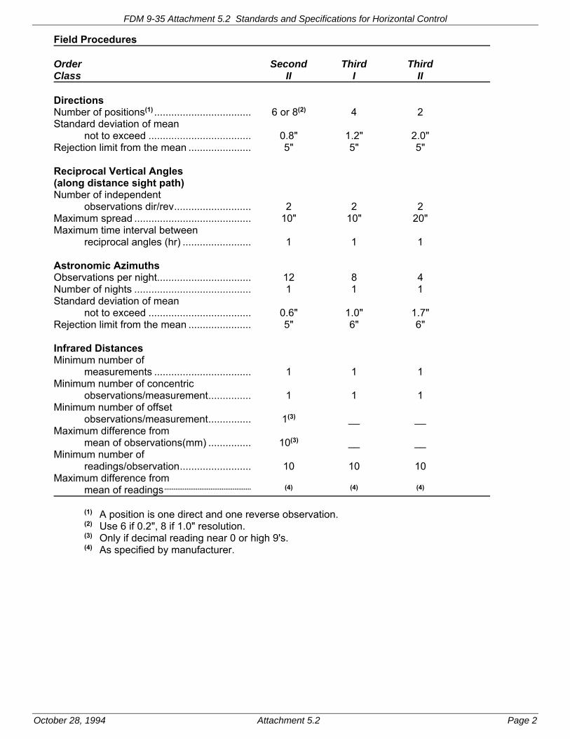
FDM 9-35 Attachment 5.2 Standards and Specifications for Horizontal Control
October 28, 1994 Attachment 5.2 Page 2
Field Procedures Order Second Third Third Class II I II Directions Number of positions(1) .................................. 6 or 8(2) 4 2 Standard deviation of mean not to exceed .................................... 0.8" 1.2" 2.0" Rejection limit from the mean ...................... 5" 5" 5" Reciprocal Vertical Angles (along distance sight path) Number of independent observations dir/rev ........................... 2 2 2 Maximum spread ......................................... 10" 10" 20" Maximum time interval between reciprocal angles (hr) ........................ 1 1 1 Astronomic Azimuths Observations per night ................................. 12 8 4 Number of nights ......................................... 1 1 1 Standard deviation of mean not to exceed .................................... 0.6" 1.0" 1.7" Rejection limit from the mean ...................... 5" 6" 6" Infrared Distances Minimum number of measurements .................................. 1 1 1 Minimum number of concentric observations/measurement ............... 1 1 1 Minimum number of offset observations/measurement ............... 1(3) __ __ Maximum difference from mean of observations(mm) ............... 10(3) __ __ Minimum number of readings/observation ......................... 10 10 10 Maximum difference from mean of readings ............................................... (4) (4) (4) (1) A position is one direct and one reverse observation. (2) Use 6 if 0.2", 8 if 1.0" resolution. (3) Only if decimal reading near 0 or high 9's. (4) As specified by manufacturer.

FDM 9-35 Attachment 5.2 Standards and Specifications for Horizontal Control
October 28, 1994 Attachment 5.2 Page 3
Office Procedures Order Second Third Third Class II I II Azimuth closure at azimuth check point (seconds of arc) ............. 4.5 ÖN 10.0 ÖN 12.0 ÖN Position closure .......................................... 0.20m ÖK 0.40m ÖK 0.80m ÖK after azimuth or or or adjustment(1) 1:20 000 1:10 000 1:5000 (N is number of newly measured segments, K is route distance in km) (1) The expression containing the square root is designed for longer lines where higher proportional accuracy is required. Use the formula that gives the smallest permissible closure. The closure (e.g. 1:10 000) is obtained by computing the difference between the computed and fixed values, and dividing this difference by K. Note: Do not confuse closure with distance accuracy of survey. Distance Accuracy Order Second Third Third Class II I II Minimum distance accuracy(1) ....................... 1:20 000 1:10 000 1:5000 (1) When a horizontal control point is classified with a particular order and class, this certifies that the geodetic latitude and longitude of that control point bear a relation of specific accuracy to the coordinates of all other points in the horizontal control network. This relation is expressed as a distance accuracy, 1:a. A distance accuracy is the ratio of the relative positional error of a pair of control points to the horizontal separation of those points. A distance accuracy, 1:a, is computed from a minimally constrained, correctly weighted least
squares adjustment by:
a = d/s
where: a = distance accuracy denominator
s = propagated standard deviation of distance between survey points obtained from the least squares adjustment
d = distance between survey points The distance accuracy pertains to all pairs of points (but in practice is computed for a sampling of pairs of points). The worst distance accuracy (smallest denominator) is taken as the provisional accuracy. If this is substantially different than the intended accuracy, then the provisional accuracy takes precedence. It is not feasible to precisely quantify "substantially different." Judgement and experience should be the determining factor.

FDM 9-35 Attachment 10.1 Sample Data Sheet for Typical Horizontal Control Station
October 28, 1994 Attachment 10.1 Page 1

FDM 9-35 Attachment 10.1 Sample Data Sheet for Typical Horizontal Control Station
October 28, 1994 Attachment 10.1 Page 2

FDM 9-35 Attachment 10.1 Sample Data Sheet for Typical Horizontal Control Station
October 28, 1994 Attachment 10.1 Page 3

Page 1
Facilities Development Manual Wisconsin Department of Transportation Chapter 9 Surveying and Mapping Section 40 Vertical Control
FDM 9-40-1 When Used October 28, 1994
The scope of an improvement project will determine the need for a vertical control survey. As a general rule of thumb most improvement projects will require vertical control. The need for vertical control is becoming increasingly important for both design and construction applications. Vertical control provides a foundation for all aspects of engineering surveys such as drainage information, subgrade preparation, environmental documentation, etc. It is also vital during the construction phases in that it provides the control necessary for proper layout and quantity computations.
FDM 9-40-5 Classification, Standards and Specifications March 14, 2016
Federal, state, and local governments, as well as private agencies make surveys, maps, and charts of various kinds that are referenced to national horizontal and vertical datums. In surveying it is necessary to establish frameworks of horizontal and vertical control so as to provide a uniform reference system with a certain stated degree of accuracy. To achieve uniformity among different agencies, certain classifications, standards and specifications must be defined and followed.
5.1 Reasons for Classification, Standards and Specifications
The primary reason for detailed classification, standards and specifications is to ensure that a desired accuracy is attained throughout a survey. This means that the accuracy is not only attained at the points of closures, but at all points in the survey. The accuracy is not accidental but is a true indication of the surveys precision. Standards and specifications will also create uniformity among surveys of the same classification. It would be impossible to achieve uniformity if surveyors use different standards and procedures for surveys of the same classification. In some instances standards and procedures may also help to prevent or minimize over-surveying. Under normal conditions, the procedures specified in this procedure will provide the closing and positional accuracies well within the standards specified.
5.2 Classification
Vertical control established by geodetic leveling methods by the Wisconsin Department of Transportation adheres to the classifications as set forth in this procedure. Attachment 5.1 details the recommended minimum classification requirements for vertical control established by geodetic leveling methods.
5.3 Standards and Specifications
Vertical control established by geodetic leveling methods by the Wisconsin Department of Transportation adheres to the standards and specifications as set forth in this procedure. Attachment 5.2 details the recommended standards and specifications for vertical control established by geodetic leveling methods.
LIST OF ATTACHMENTS
Attachment 5.1 Recommended Minimum Classification Requirements
Attachment 5.2 Standards and Specifications for Vertical Control
FDM 9-40-10 Vertical Control Data Base March 14, 2016
The present vertical control network consists of a hierarchy of interrelated networks throughout the state. Adjusted vertical NGRS data for Wisconsin is published for the NGVD 29 and NAVD 88 datums. The hierarchy is broken down into First, Second and Third Order geodetic quality benchmarks. The vertical datum to which the project will be tied should first be determined. Specifications and procedures for First, Second and Third Order leveling projects are detailed in Federal Geodetic Control Committee publication entitled "Standards and Specifications for Geodetic Control Networks" (1984) and is available at:
http://www.ngs.noaa.gov/FGCS/tech_pub/1984-stds-specs-geodetic-control-networks.htm
10.1 First-Order (Primary Network)
This class of benchmarks consists of benchmarks established approximately 2 km apart along lines of leveling throughout some parts of Wisconsin. The level lines generally follow railroad alignments and provide the most

FDM 9-40 Vertical Control
Page 2
accurate base for further densification of vertical control.
10.2 Second-Order (Secondary Network)
This class of benchmarks consists of benchmarks established approximately 2 km apart along lines of leveling spaced 10 to 50 km apart throughout Wisconsin. The level lines generally follow railroad alignments and provide an accurate base for further densification of vertical control.
10.3 Third-Order (Local Vertical Control)
This class of benchmarks was established to meet local needs for engineering and mapping projects. It is currently the densest network of benchmarks and is documented by level lines contained within the 15-minute quadrangles throughout Wisconsin.
The current database for most vertical control throughout the state is derived from hard copy format obtained from sources such as the NGS, State Cartographer's Office, United States Geological Survey (USGS) and various local agencies.
10.4 Project Order (Project Specific Vertical Control)
This class of benchmarks is established to meet the project specific needs where the region survey coordinator has determined that a transportation improvement project requires additional vertical control where the additional control does not have to meet the specifications for Third Order vertical control or above.
Project Order leveling projects for Wisconsin Department of Transportation (WisDOT) transportation improvement projects shall be tied to the Wisconsin height modernization program (HMP) network of geodetic survey control stations. The HMP stations are surveyed to Second Order Class I specifications.
Every project order level loop shall begin and end on a height modernization program station. It is desirable that the leveling crew level to other HMP stations that are along the level loop routes of a project to provide additional data checks. It is good surveying practice to observe any non HMP bench marks that are easily recoverable along a level loop route to provide additional usable bench marks and data checks.
Additional project order leveling specifications can be found in Attachment 5.1 and 5.2. Other questions not covered by these procedures can be answered by the region survey coordinator in consultation with the central office surveying and mapping section.
FDM 9-40-15 Field Reconnaissance March 14, 2016
Elevations for WisDOT improvement projects shall be referenced to the Wisconsin Height Modernization Program (HMP) passive network bench marks. The elevations for HMP bench marks are found in the National Spatial Reference System (NSRS) database of the National Geodetic Survey (NGS). On line access to this information is found at:
http://www.ngs.noaa.gov
The NGS database provides elevation data in the most current vertical datum and adjustment as well as any superseded values for bench marks nationwide.
The Wisconsin State Cartographer’s Office (SCO) website has a control finder application that will help the user to identify vertical bench marks that are in a given project area. Control finder can be found at:
http://www.sco.wisc.edu/controlfinder/controlfinder.html
The user should be cautious when using the control finder application because elevations for some non NGS station (e.g. USGS or County Control Stations) are not automatically updated to the latest NGS datum and adjustment.
The first step when performing the field reconnaissance is recovery of geodetic control survey stations for the project. A visual inspection of the station should be made in order to verify the monument description and whether it may have been disturbed. Any discrepancies or disturbances should be noted. Stations in the NGS database that are discovered to be destroyed or unusable should be reported to the appropriate NGS regional advisor. The advisor will take the necessary steps to confirm the station information and if necessary, remove it from the NSRS database.
As a part of the field reconnaissance, prepare field sketches that accurately depict the positions of existing First, Second or Third Order vertical control and the planned location of the Third Order or Project Order stations to be established. These sketches should show the lines, point numbering sequence and interconnections that are to be measured on all primary, secondary and supplemental control points. USGS quadrangle maps, aerial base documents or rough scaled hand sketches are useful for this purpose. Sketches or digital images of all elevation

FDM 9-40 Vertical Control
Page 3
stations set or used in the course of a leveling project should be documented.
FDM 9-40-20 Field Procedures March 14, 2016
Leveling is the term applied to any of the various processes by which elevations of points or differences in elevation are determined. It is a vital operation in producing necessary data for planning, mapping, design and construction. The most common method used in leveling is differential leveling. Some differential leveling techniques are as follows:
20.1 Single Run Double Simultaneous Leveling
This technique uses two parallel, independent foresight and backsight turn points for each IH. Each pair of turn points is set, if possible, at an appreciably different elevation (0.5 foot (150 mm) or more). They are also set a few feet apart so the level will have to be rotated slightly between the two rod readings. This provides a check on the instrument setup if each Instrument Height (IH) elevation agrees for the two lines. From each setup, single wire rod readings are recorded on both backsight and foresight turn points. The adjusted elevations for benchmarks from the two lines are then averaged.
20.2 Double Run Leveling
With this technique a double line of levels is run through a single line of turn points. At each setup site, two independent IH's are established at approximately 0.5 foot (150 mm) difference. From each IH a single wire rod reading is obtained on the single backsight and foresight turn point. The average adjusted elevations from the two lines are then used.
20.3 Three Wire Leveling
This technique utilizes the stadia cross hairs located within the optics of most leveling instruments. Each backsight and foresight is recorded by reading the upper and lower stadia hairs in addition to the horizontal cross hair. The three readings thus obtained are averaged to obtain the desired value. The stadia hairs are positioned an equal distance above and below the horizontal cross hair and are usually spaced to give 1.00 units of interval for each 100 units of horizontal distance between the rod and the level. This method is self checking and the accuracy of a three wire level run is equal to the mean of three lines of single wire levels through the same turn points.
20.4 Single Wire Leveling
A single line of levels is run through a single line of turn points with this method. This method provides no redundancy in observations and does not allow for discovery of errors before moving forward during the leveling procedure. This method should be used only for WisDOT project order vertical control surveys.
20.5 Reciprocal Leveling
The surveyor should always try to keep backsight and foresight distances equal during differential leveling so that instrument and natural errors cancel out. In some situations, such as river or valley crossings, this is not always possible. The reciprocal leveling technique should then be utilized; this technique is illustrated in Figure 20.1 below. The level is set up and readings are taken on TP3 and TP4. (Precision can be improved if multiple readings are taken on the turn points and then averaged.) The instrument is then moved to the other side and the process is repeated. The differences in elevation thus obtained are averaged to obtain the final result. The averaging process should eliminate instrumental and natural errors such as curvature and refraction.

FDM 9-40 Vertical Control
Page 4
Figure 20.1. Illustration of Reciprocal Leveling Technique
20.6 Trigonometric Leveling
The use of a total station as a level increases acceptable distances on sight lines and can increase production in many situations. The difference in elevation between any two points can be determined if the vertical angle (VT) and slope distance (DS) of the line from one point to the other are measured. With modern total stations, the elevation difference can be calculated automatically but an understanding of the formulas used and what the different combinations of Instrument Height (IH) and Staff Height (SH) will produce in the form of displayed or recorded results is necessary. Figure 20.2 below shows a total station measuring a slope distance and vertical angle.
Figure 20.2. Illustration of Slope Distance & Vertical Angle
The vertical distance, (DV), can be determined by the equation:
DV = DS * cos (VT)
If the ground elevation at the instrument is known,
Ground Elev @ Target = Ground Elev @ Instr + IH = DV – SH
In order to get elevation difference from ground-point to ground-point, the IH must be added and the SH subtracted from the DV. The keys to success in running trigonometric elevations is to take the mean direct and reverse readings of the vertical circle, limit sight distances to less than 1000 ft (300 m), and use proper targeting. Deviations from these procedures can result in large errors due to the effects of earth curvature and refraction.
20.7 Digital Leveling
Advances in electronics now enable surveyors to perform differential leveling with an electronic digital level. The
RIVER
TP3
TP4
SH
DV
VT
IH
DS
DH

FDM 9-40 Vertical Control
Page 5
digital level processes an electronic image of a bar coded staff for determination of heights and distances with automatic recording of the data for future processing on a computer. The digital level is an automatic level (pendulum compensator) capable of normal optical leveling with normal graduated staffs. The level can also be used with the bar coded staff and rod readings obtained digitally with output units in either metric or Standard English units.
20.8 Curvature and Refraction
All rod readings taken with a level will contain small amounts of error due to earth curvature (c) and refraction (r). The curvature of the Earth appears to make the rod ‘fall away’ as one gets farther from the instrument and causes the surveyor to read higher on the rod than intended. Refraction is created when sight lines are curved downward by the earth's atmosphere and temperature gradients and causes the surveyor to read lower on the rod than intended. Normally, the effects of earth curvature (c) and refraction (r) partially offset each other with curvature being the larger value. Curvature and refraction errors can be negated by balancing backsight (BS) and foresight (FS) distances, causing the errors to cancel out or by taking short site distances (less than 1000’). For the most part this error is small but it could be a problem on long level lines where BS and FS distances are not balanced.
Figure 20.3 below depicts the effects of curvature and refraction:
Figure 20.3 Effects of Curvature and Refraction
20.9 Peg Test
In order to measure precise elevation differences with a geodetic level it is important that the axis of sight be perpendicular to the vertical axis. A simple procedure to test and adjust for this error is termed the peg test and should be performed frequently on geodetic levels.
To perform the peg test, the surveyor first places two stakes at a distance of 200 to 300 ft (60 to 90 m) apart. The level is set up midway between the two stakes and rod readings are taken at both locations (see Figure 20.4).
If the line of sight through the level is not horizontal, the error in rod reading (E1) at both points A and B will be identical as the level is halfway between the points. Since the errors are identical, the calculated difference in elevation between points A and B will be the true difference in elevation.
The level is then moved to one of the points (A) and set up so that the eyepiece of the telescope just touches

FDM 9-40 Vertical Control
Page 6
the rod as it is being held plumb at A. The rod reading at A can then be determined by sighting backward through the objective lens at a pencil point that is being slowly moved up and down the rod. The reverse rod reading at A is then recorded and a normal rod reading at B is obtained. This computed elevation difference is then compared to the true elevation difference obtained from the first set up. The difference, if any, between the computed and the true elevation difference is the error to be corrected by adjustment. Refer to the instrument's user manual for proper adjustment procedures.
Figure 20.4. Peg Test Demonstration
20.10 Data Collection
The following items should be noted and recorded as project metadata while performing vertical control survey work for the department:
1. Project Header Information
- Task (type of leveling, e.g. single-wire leveling, 3-wire leveling, trig, etc.)
- Project ID
- Project description
- Time, date and crew
- Weather conditions, temperature and barometric pressure
- Units of angles, length, temperature and pressure
- Instrument type and serial number
- Curvature and refraction settings
Note: The data collector can be designed to prompt or measure the above information. The list above provides some of the necessary information for further computations and can be supplemented with additional information as desired.
2. Occupied Station Entries
- Station/bench mark name and/or number
- Point description (e.g. RR SPIKE IN 13" DIA OAK, brass WisDOT disk, etc.)
- Other description information about station, (such as reference ties, bridge number, etc.)
- Instrument height (applicable during trig leveling)
- X, Y, and Z coordinates if known (optional)
Note: The differential leveling tasks always begin with an occupied station activity and a backsight activity to establish an elevation at the first instrument setup. The tasks then proceed to side shot activities to establish or carry forward other elevations. Coordinates may be entered into a system control file for access just before field data reduction and adjustment if desired.
3. Sighted Station Entries (BS, FS, TP etc.)
- Station/bench mark name and/or number
- Point description (e.g. CHIS '+' IN CONC STEP, brass WisDOT disk, etc.)
- Other descriptive information data about station (such as reference ties, fire number or building
B
A
100 FT (30 M) 100 FT (30 M)
HORIZONTAL LINEHORIZONTAL LINE
LINE OF SIGHT LINE OF SIGHT
E1 E1

FDM 9-40 Vertical Control
Page 7
address, etc.)
- Staff height of rod or tripod (applicable during trig leveling)
- X, Y, and Z coordinates or fixed azimuth if known (optional)
- Measured data such as rod readings, horizontal and vertical angles and slope distances
Note:The recording of the above information will provide enough information for field data reduction, analysis and adjustment and can be supplemented with additional information as desired.
Once all the necessary data has been collected, the field crew can perform some preliminary calculations to check closure specifications while out in the field. After it has been determined that the field work meets the desired accuracy specifications, all data including any field sketches or supplemental notes should be turned over to the appropriate individual for download to PC, final adjustment, transmittal to others and archival.
FDM 9-40-25 Computations October 28, 1994
The department currently uses a variety of software packages and computer programs for data reduction and adjustment of vertical control. The correct method of operation of each package or program is described in the appropriate user manual for each. This procedure describes some of the fundamental computations that the above programs accomplish as well as provides some general guidelines for proper vertical control adjustment.
25.1 Single-Wire Adjustment
Single-wire level runs should be adjusted between two consecutive control benchmarks. The misclosure between the control benchmarks is prorated to each turning point or set of turning points. The formula for adjustment of elevations is as follows:
Adjustment = Misclosure * Number of T Ps to a Given TP
Total Number of T Ps
TP = Turning Point
25.2 Three-Wire Adjustment
The adjustment of elevations of a three-wire level circuit is based on the length of sections. A section is defined as the level run between any two benchmarks (controlling or new). The sections should be arranged in the order that the level line was run, because the computations of a line of levels is a progressive calculation. The length of a section and/or sight in meters or feet is computed by multiplying the total stadia intercept by the stadia constant for the particular instrument used.
The misclosure between the control benchmarks is adjusted proportionately to the section lengths. If the section lengths are accumulated between control benchmarks, the adjustments can be expressed in accumulated values to simplify the calculations. The formula for adjustment of elevations is as follows:
sBM'ControlBetweenLength
LengthsSection* Misclosure= Adjustment
25.3 Least Squares Adjustments
Primary level circuits involving multiple loops and/or redundant observations should be adjusted by the least squares method. In a least squares adjustment, the "best" solution is defined as the solution producing the smallest change to the original field measurements. These changes between the best-fit measurements and the original field measurements are called residuals. This method, based on the theory of probability, simultaneously adjusts the elevation differences of each separate line in the level circuit to make the sum of the squares of the weighted residuals a minimum. The corrections sought are those that produce the highest probability of their simultaneous occurrence in the level circuit.
The ability to weight individual measurements is available in the least squares package. This gives the user the extra control needed to provide the overall best adjustment. Each observation (elevation difference) can be assigned an individual weight, either mathematically derived based on the length of line or number of turn points or could be assigned a constant based on the type of instrument, method of measurement or skill of the field

FDM 9-40 Vertical Control
Page 8
crew. Lower weights can be given to less accurately known field data while higher weights can be given to observations that are more accurately known. During the adjustment, larger changes will be assigned to the less accurate data, minimizing the changes to the more accurate data.
Least squares also provides a complete analysis of the survey, including a statement on the positional accuracy of each computed point, and a list of residuals for all measurements. This analysis can help in the detection of survey blunders and areas in need of improvement. It can also assist in the preplanning of subsequent surveys. In addition, the least squares method provides a number of significant advantages over other adjustment methods:
- It computes a single solution, no matter how complex the survey.
- It does not distort field data.
- It allows more flexibility during data collection - data may be collected in any order and configuration.
The least squares method of adjustment is incorporated within the department's Polsast mainframe program and the CAiCE software package. Consult the appropriate user manual for the correct operation of each.
25.4 Accuracy Evaluations
One of the tests used to evaluate the accuracy of a vertical control circuit is to check the amount of misclosure at checkpoints or control benchmarks. The amount of misclosure is expressed in units of length and is evaluated for conformity to the desired specifications as detailed in FDM 9-40-5. The analyst should also verify conformance to the other specifications listed in FDM 9-40-5 such as minimal observation method, maximum sight distances and three-wire stadia differences.
Deviations from the desired specifications will require some further investigation into the source of the problem. If the least squares adjustment method was used the analyst should observe the residuals and error ellipses for each point in the survey. This, along with other blunder detection methods, can help to uncover errors within the survey.
FDM 9-40-35 Monumentation March 14, 2016
All third-order and project vertical control stations shall be monumented in accordance with FDM 9-25-10, usually within department owned right-of-way. For each benchmark that is established, a description should be prepared. Standard information to be recorded includes project identification, point number, general location, specific location, and descriptive information. Additional information such as vertical datum, adjusted elevation, stationing, and other project related information may be added after adjustment computations are complete.
General location information should adequately describe how to drive or walk to the benchmark from nearby landmarks or roadways and include references to a mapped highway or street, city or village, and county. General location information should also include at least one of the following types of horizontal information:
- The Global Positioning System (GPS) geographic coordinates (latitude and longitude to at least the nearest second of arc);
- A grid coordinate value (X,Y) or ground coordinate value (N,E) of any rectangular coordinate system detailed in FDM 9-20-25.3.
- Project stationing and offset from the reference line; or
- The township, range, section, and quarter-section.
Specific location information should include the distance (usually less than 100 ft) and direction from the centerline of at least one roadway (highway, street, railroad track, etc.), and the distance (usually less than 100 ft) and direction from at least two nearby prominent features (roadway, building, bridge, culvert, pole, tree, etc.).
Descriptive information should describe the type of marker/monument used as the benchmark (e.g., a chiseled square on the north end of the east bridge abutment, a bronze C&GS benchmark disk stamped E 10 1930 set in a concrete post).

FDM 9-40 Attachment 5.1 Recommended Minimum Classification Requirements
March 14, 2016 Attachment 5.1 Page 1
Recommended Minimum Classification Requirements for Vertical Control
TYPE OF SURVEY
CLASSIFICATION
Second-Order Class I 1
Third-Order 1 Project Order
Wisconsin Height Modernization Geodetic Bench Mark
X
Engineering (Project) Bench Mark X
Temporary Bench Mark X
Aerial Photogrammetry Target X
Alignment/Profile Classification, standards, and specifications for a vertical control survey in these categories are generally classified as engineering (project), but can vary by project and/or region. Contact the region survey coordinator for specific details.
Structure
Cross Section/DTM
Topography
Construction
1 Standards and specifications for establishing vertical control of this classification detailed in the Federal Geodetic Control Committee publication, “Standards and Specifications for Geodetic Control Networks,“ as reprinted in October 1990, or subsequent revisions.

FDM 9-40 Attachment 5.2 Standards and Specifications for Vertical Control
March 14, 2016 Attachment 5.2 Page 1
STANDARDS & SPECIFICATIONS FOR VERTICAL CONTROL Network Geometry Classification Third-Order Project Order Existing network BM ties (min) ........................... 4 2 Maximum distance between new bench marks ........................................ 1.8 mi (3 km) 1500 ft (450 m) Maximum length of line between BM's …. ........................................... 15 Miles (25 km) (Double-Run) N/A 6 Miles (10 km) (Single-Run)
Instrumentation Classification Third-Order Project Order Accuracy Standard deviation in 0.6 mile (1.0 km) of double run leveling ...................................... +/-0.003 ft. +/- 0.006 ft. (1.0 mm) (2.0 mm1 ) Leveling rod construction ................................... Invar, Metal Fiberglass, Metal or Wood or Wood 1An electronic total station may be used in lieu of a spirit or electronic level.

FDM 9-40 Attachment 5.2 Standards and Specifications for Vertical Control
March 14, 2016 Attachment 5.2 Page 2
Field Procedures Classification Third-Order Project Order Minimal observation method .............................. DR or 3WR SR Maximum sight length .................................... 300 ft (90 m) 300 ft (90 m1 ) Maximum difference between backsight and foresight lengths per setup ......................................... 30 ft (10 m) 30 ft (10 m) per section ....................................... 30 ft (10 m) 30 ft (10 m) Minimum ground clearance of line of sight2 ............................................. 1.6 ft (0.5 m) 0.7 ft (0.2 m) 3-wire method Maximum 3-wire stadia difference ................ 0.008 ft (2.5 mm) N/A
Maximum section misclosure ........................ 0.05√M ft (12 √K mm) 0.06√M ft (14√K mm)
Maximum loop misclosure ............................ 0.05√M ft (12 √K mm) 0.06√M ft (14√K mm)
DR -- Double-Run with single wire observation method or with digital level instrument 3WR -- Single-Run with 3-wire observation method SR -- Single-run with single-wire observation method K -- Shortest length of section (one-way) in km or perimeter of loop in km. M -- Shortest length of section (one-way) in miles or perimeter of loop in miles.
1 Maximum sight length of 1000 ft (300 m) with electronic total station provided two position vertical angles are measured. 2 For 3- wire leveling, the minimum ground clearance of the lower wire line of sight.

Page 1
Facilities Development Manual Wisconsin Department of Transportation Chapter 9 Surveying and Mapping Section 43 Planning and Scheduling
FDM 9-43-1 Minimum Data Requirements June 19, 2013
This procedure lists development surveying operations1 typically needed to meet the minimum data requirements for each of seven types of highway improvement projects. Surveying operations needed to meet the minimum data requirements for a major project will be similar to the minimum data requirements for one, or more, of the seven types of projects listed. The seven types of projects have been grouped into only four different parts for this procedure (see Attachment 1.1 for surveying operations in each part.)
The text of each part is complete and independent of any other part. The types of projects in the four parts are:
- Reconstruction, reconditioning, or expansion project
- Pavement replacement project
- Resurfacing project
- Bridge replacement or bridge rehabilitation project
In some regions, staff outside the survey unit may do some of the surveying operations listed in this procedure. After the scoping meeting, the project designer or project manager should meet with the survey unit coordinator and specify which of the listed surveying operations are needed for the project, and which surveying operations are to be performed by the survey unit. Some projects do not need all the surveying operations listed. Before deleting any surveying operations, designers should consider the possible need for each of the surveying operations to avoid inefficient project visits caused by scope creep.
1.1 Reconstruction, Reconditioning, or Expansion Project
A reconstruction project and an expansion project will usually need all of the following listed surveying operations. A reconditioning project may not need all of the following listed surveying operations. The project designer or project manager should determine the surveying operations needed for a project. Often a bridge rehabilitation or bridge replacement project is part of a reconstruction project but may also require those surveying operations listed later in this procedure for a bridge rehabilitation project or a bridge replacement project. Surveying operations usually needed for a reconstruction, reconditioning, or expansion project are listed below.
1. Find existing horizontal and vertical control, and select geodetic references. Review existing documentation for the project area to identify potential existing horizontal and vertical control including, but not limited to, as-built plans, the National Geodetic Survey Database, department and county data files, and right-of-way and transportation project plats. Reconnoiter the project area to recover existing control and determine what additional control is needed. Select for the project the:
- Horizontal Datum
- Vertical Datum
- Horizontal Coordinate System and Zone
2. Provide mapping, imagery, or other spatial data. Select the needed product(s) from the following:
- Aerial mapping/digital terrain model (DTM) data(1) (designer to cut cross sections in design software).
- Aerial expedient planimetric mapping, and field DTM or field cross sections.
- Field mapping (radial topography), and field DTM or field cross sections.
- Digital ortho imagery, and field DTM or field cross sections.
- Georeferenced imagery, and field DTM or field cross sections.
- Scanned aerial imagery.
- Aerial imagery.
- Aerial mosaic.
3. Field locate1 and document the existing pavement centerline, horizontal and vertical control monuments, and right-of-way monuments.
- Review as-built plans, plats (check with the region Plat Unit for the most recent plat), and 1. Here the word “locate” means to determine a horizontal, vertical, or three-dimensional position of a feature.

FDM 9-43 Planning and Scheduling
Page 2
existing horizontal and vertical control documentation for the project area.
- Locate new horizontal and vertical control monuments.
- Locate existing right-of-way monuments.
- Find existing Public Land Survey System (PLSS) monuments (section corners).
- Find and locate the existing highway alignment.
- Compute alignment and compare to the as-built plan, right-of-way plat, and transportation project plat. Make adjustment if necessary.
- Evaluate relative location of centerline and right-of-way.
- Check if existing right-of-way monuments are in platted locations.
- Place witness posts or lath about landmarks (property boundary monuments including PLSS monuments) and control monuments to protect them.
When determining the existing centerline of pavement, be alert to migration of asphalt pavement which is likely to move from the original alignment with each pass of the paver and with traffic. Concrete pavement is less likely to migrate. If an asphalt overlay has been placed on concrete pavement, dig to find the edge or joint of the concrete. Also be alert to widening of the pavement on only one side of the original centerline.
Centerline information may be available from either the region Real Estate Section or from the Plat Unit in the form of plat information. Information is also available from town road records, or from previous design plans. The project designer or project manager should coordinate who will merge the data for a best-fit centerline. Also, see FDM Chapter 12 and Wisconsin Administrative Code A-E 7.03. http://www.legis.state.wi.us/rsb/
4. Field locate and describe topographic features to supplement aerial mapping data.
- Locate underground utilities. See FDM 18-10-15.
- Locate easily recoverable existing property boundary monuments. Depending upon the specifics of the project, the project designer or project manager may request all property boundary monuments to be located. Researching to find all certified survey maps, plats, and associated documents for the project area may or may not be necessary for a project, and may or may not be considered surveying operations.
- Locate features not identifiable on the photographs.
- Describe features including size and material; e.g., a 24-inch diameter corrugated metal culvert pipe or a 30-foot tall blue spruce tree.
- Fill in obscure areas on the photographs as requested by the project designer; e.g., ground elevations in an area of conifer trees.
5. Field locate environmentally sensitive areas.
- Locate delineated wetlands.
- Locate other environmental features as needed to meet requirements of FDM Chapter 20.
6. Field locate critical points of structures and pipes.
- Locate pipe inverts.
- Measure overhead clearances.
- Measure other site specific dimensions.
7. Field locate (during final design) features shown on the aerial mapping.
At all project limits for aerial mapping projects, horizontal and vertical alignments should be adjusted to meet field conditions due to inherent errors in aerial mapping/DTM data. In addition, all surveys (aerial and field) should extend at least 300 feet beyond project limits so that smooth horizontal and vertical alignments can be developed between existing and proposed conditions.
8. Locate section corners for plat preparation.
Establish coordinates for all section corners in or near the project area[3]. If existing section corner coordinate values are the basis for the project control (because the section corners are the best readily available monumentation with coordinates), those coordinate values must be listed in the project documentation. If existing section corner coordinates differ from the section corner coordinates determined by using the horizontal control for the project, then the coordinate values used must be clearly listed and accompanied by the associated metadata.

FDM 9-43 Planning and Scheduling
Page 3
9. Field mark proposed right-of-way acquisition for appraisal and monument right-of-way as early as practical.
10. Perpetuate monuments of record[4].
Ensure that the county surveyor has been notified of the proposed design as approved in the Design Study Report. Notification should occur at the same time as notification to utility [5] companies. Also, provide a copy of the horizontal and vertical project control to the county surveyor.
1.2 Pavement Replacement Project
A pavement replacement project may not need all of the following listed surveying operations. The project designer or project manager should determine the surveying operations needed for a project. Surveying operations typically needed for a pavement replacement project are listed below.
1. Find existing horizontal and vertical control, and select geodetic references [1]. Review existing documentation for the project area to identify potential existing horizontal and vertical control including—but not limited to—as-built plans, the National Geodetic Survey Database, department and county data files, and right-of-way and transportation project plats. Reconnoiter the project area to recover existing control and determine what additional control is needed. Select for the project the:
- Horizontal Datum
- Vertical Datum
- Horizontal Coordinate System and Zone
2. Provide mapping, imagery, or other spatial data. Select the needed product(s) from the following:
- Aerial mapping/digital terrain model (DTM) data[2] (designer to cut cross sections in design software).
- Aerial expedient planimetric mapping, and field DTM or field cross sections.
- Field mapping (radial topography), and field DTM or field cross sections.
- Digital ortho imagery, and field DTM or field cross sections.
- Georeferenced imagery, and field DTM or field cross sections.
- Scanned aerial imagery.
- Aerial imagery.
- Aerial mosaic.
3. Field locate and document existing pavement centerline, and horizontal and vertical control.
- Review as-built plans, and existing horizontal and vertical control documentation for the project area.
- Locate new horizontal and vertical control monuments.
- Find existing Public Land Survey System (PLSS) monuments (section corners).
- Find and locate the existing highway alignment.
- Compute alignment, compare to the as-built plan, and make adjustment if necessary.
- Place witness posts or lath about landmarks (property boundary monuments including PLSS monuments) and control monuments to protect them.
When determining the existing centerline of pavement, be alert to migration of asphalt pavement, which is likely to move from the original alignment with each pass of the paver and with traffic. Concrete pavement is less likely to migrate. If an asphalt overlay has been placed on concrete pavement, dig to locate the edge or joint of the concrete. Also, be alert to widening of the pavement on only one side of the original centerline.
Centerline information may be available from either the region Real Estate Section or from the Plat Unit in the form of plat information. Information is also available from town road records, or from previous design plans. The project designer or project manager should coordinate who will merge the data for a best-fit centerline. Also, see Chapter 12 and Wisconsin Administrative Code A-E 7.03. http://www.legis.state.wi.us/rsb/
4. Field locate and describe topographic features to supplement mapping data.
- Locate underground utilities. See FDM 18-10-15.
- Locate easily recoverable existing property boundary monuments. Depending upon the specifics of the project, the project designer or project manager may request all property boundary monuments to be located. Researching to locate all certified survey maps, plats, and

FDM 9-43 Planning and Scheduling
Page 4
associated documents in the project area may or may not be necessary for a project, and may or may not be considered surveying operations.
- Locate other features not identifiable on the photographs.
- Describe features including size and material; e.g., a 24-inch diameter corrugated metal culvert pipe or a 30-foot tall blue spruce tree.
- Fill in obscure areas on the photographs as requested by the project designer; e.g., ground elevations in an area of conifer trees.
5. Field locate critical points of structures and pipes.
- Locate pipe inverts.
- Measure overhead clearances.
- Measure other site-specific dimensions.
6. Field locate (during final design) features shown on the aerial mapping. At all project limits for aerial mapping projects, horizontal and vertical alignments should be adjusted to meet field conditions due to inherent errors in aerial mapping/DTM data. In addition, all surveys (aerial and field) should extend at least 300 feet beyond project limits so that smooth horizontal and vertical alignments can be developed between existing and proposed conditions.
7. Perpetuate monuments of record. See FDM 9-5-1 and FDM 9-25-1. Ensure that the county surveyor has been notified of the proposed design as approved in the Design Study Report. Notification should occur at the same time as notification to utility companies [5]. Also, provide a copy of the horizontal and vertical project control to the county surveyor.
1.3 Resurfacing Project
A resurfacing project may not need all of the following listed surveying operations. The project designer or project manager should determine the surveying operations needed for a project. Surveying operations typically needed for a resurfacing project are listed below.
1. Find existing horizontal and vertical control, and select geodetic references[1]. Review existing documentation for the project area to identify potential existing horizontal and vertical control including—but not limited to—as-built plans, the National Geodetic Survey Database, department and county data files, and right-of-way and transportation project plats. Reconnoiter the project area to recover existing control and determine what additional control is needed. Select for the project the:
- Horizontal Datum
- Vertical Datum
- Horizontal Coordinate System and Zone
2. Provide mapping, imagery, and/or other spatial data. Select the needed product(s) from the following.
- Aerial expedient planimetric mapping, and field digital terrain model (DTM)[2] or field cross sections.
- Field mapping (radial topography), and field DTM or field cross sections.
- Digital ortho imagery, and field DTM or field cross sections.
- Georeferenced imagery, and field DTM or field cross sections.
- Scanned aerial imagery.
- Aerial imagery.
- Aerial mosaic.
- Line diagram of centerline.
3. Field locate and document existing pavement centerline, and horizontal and vertical control. The project designer or project manager should decide early in the project if a best-fit alignment is needed and if so who will be responsible for performing the surveying operations.
- Review as-built plans, and existing horizontal and vertical control documentation for the project area.
- Locate new horizontal and vertical control monuments.
- Find existing Public Land Survey System (PLSS) monuments (section corners).
- Find and locate the existing highway alignment.
- Compute alignment, compare to the as-built plan, and make adjustment if necessary.
- Place witness posts or lath about landmarks (property boundary monuments including PLSS

FDM 9-43 Planning and Scheduling
Page 5
monuments) and control monuments to protect them.
When determining the existing centerline of pavement, be alert to migration of asphalt pavement which is likely to move from the original alignment with each pass of the paver and with traffic. Concrete pavement is less likely to migrate. If an asphalt overlay has been placed on concrete pavement, dig to locate the edge or joint of the concrete. Also be alert to widening of the pavement on only one side of the original centerline.
Centerline information may be available from the district Real Estate Section or the Plat Unit in the form of historical and/or the most recent plat information, from Town Road Records, or from previous design plans. The project designer or project manager should coordinate who will merge the data for a best-fit centerline. Also, see FDM Chapter 12 and Wisconsin Administrative Code A-E 7.03. http://www.legis.state.wi.us/rsb/
4. Field locate and describe topographic features to supplement mapping data in areas where spot improvements are proposed.
- Locate underground utilities. See FDM 18-10-15.
- Locate easily recoverable existing property boundary monuments.
- Locate other features not identifiable on the photographs.
- Describe features including size and material; e.g., a 24-inch diameter corrugated metal culvert pipe or a 30-foot tall blue spruce tree.
- Fill in obscure areas on the photographs as requested by the projector designer; e.g., ground elevations in an area of conifer trees.
5. Field locate critical points of structures and pipes.
- Locate pipe inverts.
- Measure beam guard heights.
- Measure overhead clearances.
- Measure other site specific dimensions.
6. Field locate (during final design) features shown on the aerial mapping. At all project limits for aerial mapping projects, horizontal and vertical alignments should be adjusted to meet field conditions due to inherit errors in aerial mapping/DTM data. In addition, all surveys (aerial and field) should extend at least 300 feet beyond project limits so that smooth horizontal and vertical alignments can be developed between existing and proposed conditions.
7. Perpetuate monuments of record. Ensure that the county surveyor has been notified of the proposed design as approved in the Design Study Report [4]. Notification should have occurred at the same time as notification to utility companies [5]. Also, provide a copy of the horizontal and vertical project control to the county surveyor.
1.4 Bridge Replacement or Bridge Rehabilitation Project
If bridge replacement or bridge rehabilitation is a part of a reconstruction project, perform the surveying operations for the reconstruction project and provide the requested field information for the appropriate structure survey report. For more information regarding Structure Survey Reports (SSRs), refer to Bridge Manual Chapter 6. If the bridge replacement or bridge rehabilitation project is not part of a reconstruction project, the following listed surveying operations will usually be required. The project designer or project manager should determine the surveying operations needed for a project.
1. Provide field information for the appropriate Structure Survey Report. Select one of the structure survey report forms (DT1694, DT1696, DT1698) available online from the WisDOT Internet forms catalog.
2. Find existing horizontal and vertical control, and select geodetic references. [1] Review existing documentation for the project area to identify potential existing horizontal and vertical control including—but not limited to—as-built plans, the National Geodetic Survey Database, Department and county data files, and right-of-way and transportation project plats. Reconnoiter the project area to recover existing control and determine what additional control is needed. Select for the project the:
- Horizontal Datum
- Vertical Datum
- Horizontal Coordinate System and Zone
- Units

FDM 9-43 Planning and Scheduling
Page 6
3. Field locate and document the existing pavement centerline, horizontal and vertical control monuments, and right-of-way monuments.
- Review as-built plans, plats (check with the region Plat Unit for the most recent plat), and existing horizontal and vertical control documentation for the project area.
- Locate new horizontal and vertical control monuments.
- Locate existing right-of-way monuments.
- Find existing Public Land Survey System (PLSS) monuments (section corners).
- Find and locate existing highway alignment.
- Compute alignment and compare to the as-built plan, right-of-way plat, and transportation project plat; make adjustment if necessary.
- Evaluate relative location of centerline and right-of-way.
- Check if existing right-of-way monuments are in platted locations.
- Place witness posts or lath about landmarks (property boundary monuments including PLSS monuments) and control monuments to protected them.
When determining the existing centerline of pavement, be alert to migration of asphalt pavement which is likely to move from the original alignment with each pass of the paver and with traffic. Concrete pavement is less likely to migrate. If an asphalt overlay has been placed on concrete pavement, dig to locate the edge or joint of the concrete. Also, be alert to widening of the pavement on only one side of the original centerline.
Centerline information may be available from either the region Real Estate Section or from the Plat Unit in the form of plat information. It is also available from town road records, or from previous design plans. The project designer or project manager should coordinate who will merge the data for a best-fit centerline. Also, see Chapter 12 and Wisconsin Administrative Code A-E 7.03 http://www.legis.state.wi.us/rsb/.
4. Field locate and describe topographic features.
- Locate underground utilities. See FDM 18-10-15.
- Locate easily recoverable existing property boundary monuments. Depending upon the specifics of the project, the project designer or project manager may request all property boundary monuments be located. Researching to find all certified survey maps, plats, and associated documents for the project area may or may not be necessary for a project and may or may not be considered surveying operations.
5. Field locate environmentally sensitive areas.
- Locate delineate wetlands.
- Locate other environmental features as needed to meet the requirements.
6. Field locate critical points of structures and pipes.
- Locate pipe inverts.
- Measure overhead clearances.
- Measure other site-specific dimensions.
7. Field locate features during final design. All surveys should extend at least 300 feet beyond project limits so that smooth horizontal and vertical alignments can be developed between existing and proposed conditions.
8. Perpetuate monuments of record. See FDM 9-5-1 and FDM 9-25-1. Ensure that the county surveyor has been notified of the proposed design as approved in the Design Study Report. Notification should have occurred at the same time as notification to utility companies. Also, provide a copy of the horizontal and vertical project control to the county surveyor.
1.5 References
[1] See FDM 9-5-10.
[2] See FDM 9-45-2, Aerial Projects, Image Products. For more information on DTMs see Section 9-65.
[3] See FDM 9-5 Attachment 5.1.
[4] See FDM 9-5-1 and FDM 9-25-1.
[5] See FDM 18-10-1.

FDM 9-43 Planning and Scheduling
Page 7
LIST OF ATTACHMENTS
Attachment 1.1 Surveying Operations to Meet Minimum Data Requirements
FDM 9-43-5 Survey Time Frame October 25, 2002
The time span from a request for a survey to plans ready for letting will vary depending on the length, complexity, and scope of an improvement project. It can range from less than a year to many years for a complex reconstruction project. Factors such as environmental impact, right-of-way acquisitions, and complexity of project should be considered.
The following lead times for requesting surveys should be incorporated into project schedules.
Two Years
The survey should be requested 2 years before the start of preliminary design for reconstruction, reconditioning, expansion, pavement replacement, or bridge replacement highway improvement projects which will use:
- Aerial survey products,
- Consultant services, or
- Traditional ground survey methods.
This much lead time is needed to prepare for and to acquire the aerial imagery (3 to 14 months), and to compile the data after the flight (2 to 12 months). The most significant reason for planning ahead is that adequate aerial imagery can be acquired only in the spring (after the snow melts and before the trees have leaves, see FDM 9-45-10). A request for imagery received by December allows sufficient time to schedule aerial imagery for thefollowing spring flight, 3 months later. A request for imagery received after December may result in the aerialimagery acquisition not being scheduled until the next spring, 15 months later. A request for a consultant surveyneeds to allow time to prepare the contract. A request for consultant or department ground survey should besubmitted sufficiently early to allow performing the survey during a time of year that is most efficient forsurveying. Survey costs can escalate when surveying in a densely foliated area or in deep snow. Even a lightcovering of snow can hide significant features from the surveyor.
Seven Months
For highway improvement projects that will not use aerial survey products, the survey should be requested at least 7 months before the start of preliminary design. The time needed to bring engineering control to a project varies significantly from project to project and ample time should be allowed to accomplish this survey activity. Surveying work is affected by seasonal conditions and is usually conducted most expeditiously during periods of no leaves on the trees and no snow on the ground.
Two Months
Permanent right-of-way monumentation should be requested a minimum of 2 months before the desired completion date. An additional 2 weeks should be allowed for every 5 miles of project length beyond 5 miles. Additional time should be allowed for urban areas or otherwise complex areas. Permanent right-of-way monuments should be placed in accordance with FDM 9-25-6.
One Month
Temporary right-of-way staking for appraisal purposes only should be requested 1 month before the desired completion date. An additional 1 week should be allowed for every 5 miles of the project length beyond 5 miles. Additional time should be allowed for urban areas, if the project is in an area without a recent project, or if no existing right-of-way monuments are in the immediate vicinity of the project.
For more information on:
- Highway improvement projects and the survey activities needed for each, refer to FDM 9-43-1, Minimum Data Requirements.
- Aerial imagery products and services, refer to FDM 9-45-2, Image Products, and FDM 9-45-3, Mapping Products.
- Products and services available from the Surveying & Mapping Section, refer to the online Surveying & Mapping Catalog.

FDM 9-43 Attachment 1.1 Surveying Operations to Meet Minimum Data Requirements
October 25, 2002 Attachment 1.1 Page 1
SURVEYING OPERATIONS TO MEET MINIMUM DATA REQUIREMENTS
Type of Reconstruction, Pavement Replacement Resurfacing Bridge Replacement or Project Reconditioning, or Bridge Rehabilitation
Expansion
Step 1 Find existing horizontal and
vertical control, and select geodetic references
Find existing horizontal and vertical control, and select geodetic references
Find existing horizontal and vertical control, and select geodetic references
Provide field information for the structure survey report
2 Provide mapping, imagery, and digital spatial data
Provide mapping, imagery, and digital spatial data
Provide mapping, imagery, and digital spatial data
Find existing horizontal and vertical control, and select geodetic references
3 Field locate and document existing pavement centerline, horizontal and vertical control monuments, and right-of-way monuments
Field locate and document existing pavement centerline, and horizontal and vertical control monuments
Field locate and document existing pavement centerline, and horizontal and vertical control monuments
Field locate and document existing pavement centerline, horizontal and vertical control monuments, and right-of-way monuments
4 Field locate and describe topographic features, utilities, and property monuments
Field locate and describe topographic features, utilities, and property monuments
Field locate and describe topographic features, utilities, and property monuments
Field locate and describe topographic features, utilities, and property monuments
5 Field locate environmentally sensitive areas
Field locate critical points of structures and pipes
Field locate critical points of structures and pipes
Field locate environmentally sensitive areas
6 Field locate critical points of structures and pipes
Field locate features shown on the aerial mapping
Field locate features shown on the aerial mapping
Field locate critical points of structures and pipes
7 Field locate features shown on the aerial mapping
Perpetuate monuments of record Perpetuate monuments of record
Field locate features during final design
8 Locate section corners Perpetuate monuments of record
9 Field mark proposed right-of-way acquisition for appraisal
10 Monument right-of-way at time of acquisition
Note: The name of the surveying operation listed above may be similar for more than one type of project; however, the surveying operations may differ slightly. Therefore, the user is advised to refer to the text to learn the level of effort and the options available for collecting the appropriate data for a specific type of project. 11 Perpetuate monuments of record

Page 1
Facilities Development Manual Wisconsin Department of Transportation Chapter 9 Surveying and Mapping Section 45 Geospatial Projects
FDM 9-45-1 General April 16, 2015
The Surveying & Mapping Section coordinates all requests for products and services produced through photogrammetric methods (aerial imagery) and related sensor technologies (LiDAR scanning) as directed in the FDM 9-5-15 policy statement. Region staff should direct requests for aerial imagery and LiDAR products to the region survey coordinator. Other DOT staff may contact [email protected]. Consultants should request aerial imagery and LiDAR products through the DOT project manager (see FDM 9-5-15).
Aerial imagery is used to acquire data that is required for planning, designing, constructing, and maintaining transportation facilities. The most common data derived from aerial imagery is planimetric mapping (PMAP) and digital terrain model (DTM) data. Aerial imagery is also an excellent reference for historical, environmental and land use studies, public displays, and to support legal actions.
Unmanned Aircraft Systems (a.k.a. UAS, UA, UAV, drones) are an emerging technology. See FDM 9-45-30 for further information.
See Attachment 1.1 for a list and descriptions of available Geospatial Products.
Request Considerations
Before requesting products the project manager, project designer, and survey coordinator should consider the following.
1. Type of Project - Different types of projects (see FDM 3-5-2) will require different types and amounts of data acquisition to support the design of the project (see FDM 9-43-1).
2. Terrain and Geographic Area - In heavily wooded areas, field survey methods may be more advantageous to produce necessary elevation information than aerial photogrammetry. Aerial mapping photogrammetry methods require a clear view of the ground surface and can be supplemented with field survey methods for obscure areas.
In high traffic areas and in rolling, rugged, or hilly terrain, aerial photogrammetry methods may be more expedient and safer for field personnel. In an area with many owners/occupants and particularly with an uncooperative owner/occupant, aerial photogrammetry may save time by eliminating the need for field personnel to obtain the cooperation of each owner/occupant so field survey methods can be used.
3. Size of Project and Region Workload - Projects requiring a large amount of data may be expedited by using aerial imagery or LiDAR. Small projects may be accomplished by LiDAR or field survey methods.
4. Time Frame - The time frame of requesting aerial imagery or LiDAR, the requested delivery date, and type of product needed may be significant in determining the method of data acquisition. Some types of data acquisition are dependent upon the season of the year (see FDM 9-43-5 and FDM 9-45-15).
5. Multiple Counties - When using the Wisconsin County Coordinate System (WCCS) or the Wisconsin Coordinate Reference System (WISCRS), there are several options to consider at county boundaries. Depending upon how far the project extends into the adjacent county, the coordinates for the project may be in the same county zone for the entire project, may need to be shown in both county zones, or may be shown in one county zone for part of the project and in the other county zone for another part of the project (see FDM 9-20-27 and FDM 9-20-28).
LIST OF ATTACHMENTS
Attachment 1.1 Geospatial Products

FDM 9-45 Geospatial Projects
Page 2
FDM 9-45-5 Aerial Imagery Products April 16, 2015
FDM 9-45 Attachment 5.1 provides examples of aerial imagery products listed in Table 5.1. Region staff should request aerial imagery products through the region survey coordinator. Other DOT staff may contact [email protected]. Consultants should request aerial imagery products through the DOT project manager (see FDM 9-5-15).
Table 5.1 List of Aerial Imagery Products
Subsection Product Name Product Description
FDM 9-45-5.1 Vertical Aerial Imagery
Stand-alone product
Required for all aerial photogrammetry products (FDM 9-45-10.1 to 10.5)
Required for Products FDM 9-45-5.2 and 5.3
FDM 9-45-5.2 Digital Aerial Mosaic Stand-alone product
FDM 9-45-5.3 Digital Geo-Referenced Imagery
(GeoRef) Stand-alone product
FDM 9-45-5.4 Oblique Aerial Imagery Stand-alone product
5.1 Vertical Aerial Imagery
Vertical aerial imagery is captured using a calibrated photogrammetric camera located in the bottom of an aircraft. The camera axis is pointed vertically so that the film surface is approximately parallel to the earth's surface. Vertical aerial imagery is acquired using black and white aerial film, or may be acquired using a digital photogrammetric camera. Aerial film is scanned into digital format for a variety of uses. Other types of film (color or infrared) may be used, but are rarely needed for transportation projects and are more expensive and difficult to use than black and white film.
Vertical aerial imagery which has an analytical triangulation solution is called controlled imagery. Vertical aerial imagery which does not have surveyed ground control nor an analytical triangulation solution is uncontrolled imagery.
Due to distortions caused by ground relief and radial position in the image, the resulting raw image is not as accurate as a map for quantitative measurements. The image may be used to create a digital imagery product with improved accuracy, such as a geo-referenced image (see FDM 9-45-5.3) or a digital ortho image (see FDM 9-45-10.5) can be produced.
New vertical aerial imagery has a typical scale of approximately 1 inch = 250 feet, resulting in a map with a scale of 1 inch = 50 feet, but the scale for each project will be determined based on the intended use and accuracy needed.
An index to vertical aerial imagery acquired after 1998 is available through DOTView. Older archived statewide imagery can be researched by aerial imaging staff when township, range, and section or address is provided. Reproductions are available as digital files or inkjet plots. Files are delivered via the LAN or externally via FTP. Imagery is typically scanned at 600 dpi, but varies by needs. Requests should include the roll and exposure number of existing imagery (from DOTView, unless ordering new imagery) and a map indicating the area to be enlarged. Indicate the requested scale, size and resolution of the finished product; and whether a digital file or print is desired. Aerial imagery staff can offer advice regarding product scale, resolution and file format based on intended use.
Vertical aerial imagery may be used for:
- Plan sheets
- Engineering exhibits
- Land use drawings
- Resurfacing plans
- Qualitative information such as land use, soils, vegetation type, and geology
- Exhibits in reports and legal documents
- Exhibits at public meetings

FDM 9-45 Geospatial Projects
Page 3
- Monitoring land use and changing conditions
- Digital mosaics
- Geo-referenced imagery
- Ortho imagery
5.2 Digital Aerial Mosaic
A digital mosaic consists of two or more aerial images that have been scanned to produce raster files and are then overlapped to form a single continuous image. Digital mosaics can be produced from ortho imagery, geo-referenced imagery or uncontrolled scanned vertical aerial imagery.
Requests for digital mosaics from previously acquired imagery should include the roll and exposure number of existing imagery (from DOTView) and a map indicating the area. Also indicate the requested resolution of the finished product and the desired file format (unless a print is desired). Aerial imagery staff can offer advice regarding product scale, resolution, and file format based on intended use.
Digital aerial mosaics may be used for:
- Photo indexes
- Design investigations
- Report illustrations
- Resurface plan sheets
5.3 Digital Geo-referenced Imagery
A geo-referenced image is a raster aerial image that has been warped to fit points from a vector file or visible points from a coordinate correct raster image (i.e. an existing ortho or georef). Georeferenced imagery is less accurate than ortho imagery and does not have a guaranteed accuracy.
Requests for digital geo-referenced imagery from previously acquired imagery should include the roll and exposure number of existing imagery (from DOTView) and a map indicating the area. Also, indicate the requested resolution of the finished product and the desired file format (unless a print is desired). Aerial imagery staff can offer advice regarding product scale, resolution, and file format based on intended use.
Geo-referenced imagery may be used for:
- Plan sheets
- Engineering exhibits
- Land use drawings
- Mosaics
- Exhibits for public meetings
5.4 Oblique Aerial Imagery
Oblique aerial imagery is taken with the camera axis inclined at an angle to the surface of the earth. If the horizon shows in the image, it is a high oblique. If the horizon does not show, the image is a low oblique.
Color oblique aerial imagery is taken with a high resolution digital single-lens reflex camera, which is held out the window of the aircraft as the pilot circles the subject area. This product is useful when a broad area of coverage is needed for display purposes. The images can be delivered as digital files or digital inkjet plots.
Requests should include a county map which shows the location requested. Also include additional maps (e.g., quad map, city plat, or aerial mosaic) to highlight the specific area to be photographed. Indicate the type of oblique (i.e., high or low) and the desired file format or whether prints are desired. To request additional prints or enlargements from existing obliques, provide the oblique number(s) and the quantity and enlargement size desired. Aerial imagery staff can offer advice regarding resolution and file format based on intended use.
Oblique aerial imagery may be used for:
- Displays for public informational meetings
- Design reports
- Design awards
- Documentation of existing / changing conditions
LIST OF ATTACHMENTS
Attachment 5.1 Aerial Imagery Product Examples

FDM 9-45 Geospatial Projects
Page 4
FDM 9-45-10 Aerial Photogrammetry Products April 16, 2015
Aerial Photogrammetry products require vertical stereo imagery, ground control and an analytical triangulation solution. A list of all aerial photogrammetry products is included in Table 10.1.
Table 10.1 List of Aerial Photogrammetry Products
Subsection Product Name Product Description
FDM 9-45-10.1 Digital Terrain Model (DTM) Stand-alone or with PMAP, Required for ORTHO
FDM 9-45-10.1 High-Flight DTM (HFDTM) Stand-alone or with PMAP, Required for ORTHO
FDM 9-45-10.1 Final DTM (FDTM) Stand-alone product
FDM 9-45-10.2 Planimetric Map (PMAP) Stand-alone or with DTM
FDM 9-45-10.3 Expedient Planimetric Map (EXP) Stand-alone product
FDM 9-45-10.4 Extensions to DTM and Mapping
Products Request as needed
FDM 9-45-10.5 Digital Ortho Imagery (ORTHO) Requires a DTM to be produced
A pair of vertical aerial images that overlap by 60% creates a stereo model. When viewed through a stereoscope, stereo plotting instrument, or digital softcopy station, the stereo model is viewed in three-dimensions. The stereo model is the basis for creating maps and collecting DTM data by the photogrammetry process.
Ground control consists of targets painted or placed on the ground or surveyed photo identifiable points (see FDM 9-45-35). The targets and photo identifiable points are surveyed as close to the time of flight as possible.
Analytical triangulation is a mathematical process of measuring the ground control and fourteen additional locations on each stereo model. An analytical triangulation solution is the result of a polynomial adjustment of all of the measurements and compensates for relief displacement and radial distortion at all locations in the stereo model. The analytical triangulation solution ties the imagery to the earth’s surface to allow accurate compilation of the earth’s features and accurate collection of horizontal and vertical data.
FDM 9-43-1 provides a list of suggested mapping products correlated to various improvement projects.
FDM 9-45 Attachment 1.1 summarizes accuracy and related information. Region staff should request DTM and mapping through the region survey coordinator. Other DOT staff may contact [email protected]. Consultants should request DTM and mapping through the DOT project manager (see FDM 9-5-15).
10.1 Digital Terrain Model (DTM)
Mapping and digital terrain model (DTM) data is critical to transportation improvement projects. A DTM is used to investigate alignment alternatives, to cut cross sections, to cut profiles, to generate contours, and to generate quantities between existing and final surfaces. Reference FDM 9-65 for more information on surface modeling.
A digital terrain model (DTM) is a mathematical model of the existing earth's surface.
Data collection is performed using 3D stereoscopic systems (stereoplotter or softcopy workstation) interfaced to MicroStation. The operator collects sufficient points to define the surface and adds break lines to define sharp changes in elevation (curbs, ditches, etc.). The points and break lines are used to create a triangulated irregular network (TIN) from which the DTM is generated.
A DTM can also be generated from LiDAR point cloud data (see FDM 9-45-20).
The data is collected in a 3D MicroStation format and the DTM data is delivered in an ASCII formatted SRV file along with a LOG file that lists the number and type of break lines and points that are in the dataset. A delivery email message is sent to the region survey coordinator and CADD coordinator. The region survey data coordinator will then determine if the obscured areas need supplemental survey data. The region survey data coordinator will then forward the data to designers. The MicroStation DGN files and DTM files are archived in the File Cabinet storage system.
These methods are used to offer various products:

FDM 9-45 Geospatial Projects
Page 5
- DTM (DTM) - final design grade accuracy used for design of improvement projects; typically delivered with the planimetric mapping.
- High-Flight DTM (HFDTM) - planning grade accuracy used for investigating corridors; typically delivered with the planimetric mapping.
- Final DTM (FDTM) - flown and compiled to final grade accuracy after the contractor has completed the earthwork such that the data can be used for construction final quantity measurements.
DTM data may be used for:
- Preliminary design
- Final design
- Drainage studies
- Structure survey report
- Plan sheets
- Right of way sheets
- Exhibits at public meetings
- Highway corridor studies
- Earthwork computations (finals)
- Creation of ortho imagery
- Areas of unique design
- Land use studies
10.2 Planimetric Map
A planimetric map depicts the horizontal position of natural and constructed features. A planimetric map (PMAP) may be a stand-alone product, but the imagery is tied to horizontal and vertical ground control so that a DTM may also be provided. Features are depicted by standardized lines and cells as specified in FDM 15-5. The features are collected in three-dimensions but are converted to a two-dimensional file for use in Civil 3D. The MicroStation 2d file is exported to a DWG, then imported and exploded in Civil 3D for highway design.
A planimetric map may be used for:
- Plan sheets
- Right of way sheets
- Preliminary design
- Final design
- Railroad abandonment project
- Structure survey reports
10.3 Expedient Planimetric Map
An expedient planimetric map depicts the horizontal position of natural and constructed features; vertical information is not included. Expedient planimetric maps are usually compiled from aerial imagery at a higher altitude and may be taken either in the spring or fall. This imagery cannot be used for DTMs because vertical information is not provided to control the imagery, however this imagery may be geo-referenced (see FDM 9-45-5.3).
An expedient planimetric map may be used for:
- Geo-referenced imagery
- Corridor location study
- Preliminary design
- Final design
10.4 Extensions to DTM and Mapping Products
One of the advantages of Photogrammetry is the ability to gather more data from the aerial imagery after analytical triangulation has been performed. For example, a designer may determine they need more data along a side road. The designer then asks the region survey coordinator to request an extension. The region survey coordinator works with the Photogrammetry Unit to determine if the existing imagery and ground control placement on the imagery will allow the collection of additional data.
Extensions may be requested on aerial imagery that is up to ten years old.

FDM 9-45 Geospatial Projects
Page 6
10.5 Digital Ortho Imagery
An ortho image is a raster aerial image with distortions removed. It looks like an aerial photograph, but has the geometric characteristics of a stereo-compiled map drawn to scale. The ortho image can provide a designer with more information than traditional vector mapping, and it can provide the public with a better concept of a highway project.
Ortho imagery is produced by draping a scanned vertical aerial image over a Triangulated Irregular Network (TIN) file produced from a Digital Terrain Model (DTM) and a camera orientation parameter file generated from analytical triangulation. Ortho imagery can be produced from existing or newly requested imagery and the corresponding DTM.
Requests for digital ortho imagery from previously acquired imagery should include the roll and exposure number of existing imagery (from DOTView) and a map indicating the area. Also, indicate the requested resolution of the finished product and the desired file format (unless a print is desired). Aerial imagery staff can offer advice regarding product scale, resolution and file format based on intended use.
Digital ortho imagery may be used for:
- Plan sheets
- Engineering exhibits
- Land use maps
- Exhibits for public meetings
LIST OF ATTACHMENTS
Attachment 10.1 Geospatial Product Examples
FDM 9-45-15 Aerial Photogrammetry Work Flow April 16, 2015
Acquisition of quality imagery requires optimal conditions to produce a quality product. Attachment 15.1 shows the work flow required for Aerial Photogrammetry products (see FDM 9-45-10) and is detailed below. If the request is for uncontrolled products from vertical aerial imagery (see FDM 9-45-5.1) follow step 1 below.
1. Region staff should request projects through the region survey coordinator. Other DOT staff may contact [email protected]. Consultants should request photogrammetric services through the DOT project manager (see FDM 9-5-15).
Fall and spring aerial photogrammetry flights should be requested as early as possible. As a guideline, fall requests should be received by August 15 and spring requests should be received by September 15. Requests received past these guidelines can be accommodated, but will receive lower priority in the mapping schedule.
Requests for mapping and DTM products should include the following:
- valid project ID
- project mileage
- project limits, highway, county
- coordinate system, horizontal datum, and vertical datum (in accordance with FDM 9-5-10)
- type of mapping and other imagery product(s) needed
- mapping due date (ortho due date, if needed)
- A scan of county map(s) showing the general project area with the project extents highlighted.
- A large-scale map showing the specific project area with details for the begin and end limits and the width of data needed left and right of the mainline and side roads.
2. The region or consultant surveyor researches appropriate horizontal and vertical ground control.
- Wisconsin Continuously Operating Reference Stations (WISCORS) network
- Wisconsin Height Modernization Project (WHMP) network
- National Geodetic Survey (NGS) geodetic control
- County networks
- United States Geological Survey (USGS) control
- Control from past DOT projects
Suggested resources include:

FDM 9-45 Geospatial Projects
Page 7
- the Wisconsin State Cartographer’s Office (SCO) ControlFinder (http://www.sco.wisc.edu/controlfinder/controlfinder.html)
- NGS DSWorld (plots NGS network points by state, county and type (vertical or horizontal) in Google Earth (which must be installed first) (http://www.ngs.noaa.gov/PC_PROD/PARTNERS/index.shtml)
Ground control established by the Department is available from the region survey office. The surveyor may need to extend ground control to the project area if adequate nearby control is not available (refer to FDM 9-45-35.1 and FDM 9-45-35.2).
3. Photogrammetry staff prepares a digital target document. The target document is typically a PDF with Google Earth imagery as a backdrop to the display of flight lines and the stereo models created by the overlapping pairs of images. The target document also identifies the locations of all needed targeted ground control points. Photogrammetry staff sends the document to the region survey coordinator along with an ASCII GCP (ground control point) file of target names and coordinates. The region survey coordinator reviews the target document to ensure the proposed flight lines and stereo models cover the requested area and to determine if additional coverage or revisions are needed. The region survey coordinator provides confirmation to the Photogrammetry Unit that each target document is acceptable.
4. Photogrammetry staff and the surveyor work together to revise the target document to accommodate field conditions and to consider using existing horizontal and vertical control within project limits.
5. Photogrammetry staff prepares the mapping schedule to identify interim due dates (e.g., ground control) in order to meet delivery due dates. Dates will be discussed with the region before being entered into the Photogrammetry Unit Milestone database. Deadlines can be renegotiated between the regions and the Photogrammetry Unit throughout the year.
6. The surveyor places targets at the designated locations. The surveyor should contact Photogrammetry staff for advice when the target cannot be placed as planned. The surveyor notifies Photogrammetry when all targets have been placed and field conditions are suitable for the flight to proceed.
7. Photogrammetry staff acquires aerial imagery at the optimum time (refer to Table 15.1).
Table 15.1 List of Aerial Photogrammetry Products
Spring (March - May) Fall (October - November) Anytime
Spring imagery is suitable for any mapping project including those
that require DTM because vegetation is matted down from
the snow.
Fall imagery may be used for final DTM due to the lack of vegetation in the recently constructed roadway.
Vertical and oblique imagery for special projects such as wetlands, special events,
airports, construction exhibits.
Before trees and bushes leaf out.
After most trees and bushes have lost leaves and ground cover plants
(including weeds) do not have leaves.
For obliques, consider fall color to enhance exhibits.
The ground, including ditches, is snow free. Snow drift studies
Water is not standing in fields or ditches, except perhaps in an occasional ditch.
Flood studies
The area is cloud free.
The winds aloft are acceptable.
8. Photogrammetry processes film as soon as possible after acquisition to determine if quality of imagery is acceptable or if the area needs to be reflown (e.g., due to shadows from clouds, missing coverage, etc.).
9. Photogrammetry evaluates the imagery for quality and finds all visible targets. When imagery is approved, Photogrammetry notifies the surveyor to remove plastic targets. If some targets are not visible on the imagery, Photogrammetry may select image points and ask the surveyor to provide coordinates. Photogrammetry scans aerial film negatives into digital raster files.
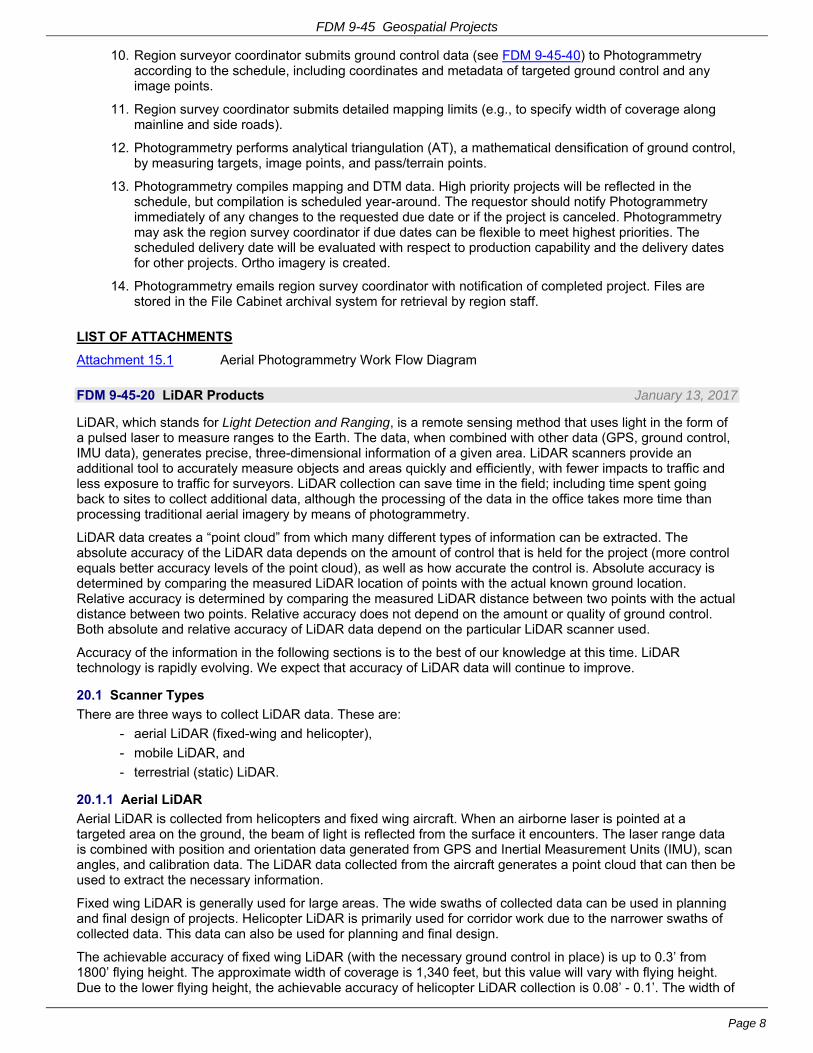
FDM 9-45 Geospatial Projects
Page 8
10. Region surveyor coordinator submits ground control data (see FDM 9-45-40) to Photogrammetry according to the schedule, including coordinates and metadata of targeted ground control and any image points.
11. Region survey coordinator submits detailed mapping limits (e.g., to specify width of coverage along mainline and side roads).
12. Photogrammetry performs analytical triangulation (AT), a mathematical densification of ground control, by measuring targets, image points, and pass/terrain points.
13. Photogrammetry compiles mapping and DTM data. High priority projects will be reflected in the schedule, but compilation is scheduled year-around. The requestor should notify Photogrammetry immediately of any changes to the requested due date or if the project is canceled. Photogrammetry may ask the region survey coordinator if due dates can be flexible to meet highest priorities. The scheduled delivery date will be evaluated with respect to production capability and the delivery dates for other projects. Ortho imagery is created.
14. Photogrammetry emails region survey coordinator with notification of completed project. Files are stored in the File Cabinet archival system for retrieval by region staff.
LIST OF ATTACHMENTS
Attachment 15.1 Aerial Photogrammetry Work Flow Diagram
FDM 9-45-20 LiDAR Products January 13, 2017
LiDAR, which stands for Light Detection and Ranging, is a remote sensing method that uses light in the form of a pulsed laser to measure ranges to the Earth. The data, when combined with other data (GPS, ground control, IMU data), generates precise, three-dimensional information of a given area. LiDAR scanners provide an additional tool to accurately measure objects and areas quickly and efficiently, with fewer impacts to traffic and less exposure to traffic for surveyors. LiDAR collection can save time in the field; including time spent going back to sites to collect additional data, although the processing of the data in the office takes more time than processing traditional aerial imagery by means of photogrammetry.
LiDAR data creates a “point cloud” from which many different types of information can be extracted. The absolute accuracy of the LiDAR data depends on the amount of control that is held for the project (more control equals better accuracy levels of the point cloud), as well as how accurate the control is. Absolute accuracy is determined by comparing the measured LiDAR location of points with the actual known ground location. Relative accuracy is determined by comparing the measured LiDAR distance between two points with the actual distance between two points. Relative accuracy does not depend on the amount or quality of ground control. Both absolute and relative accuracy of LiDAR data depend on the particular LiDAR scanner used.
Accuracy of the information in the following sections is to the best of our knowledge at this time. LiDAR technology is rapidly evolving. We expect that accuracy of LiDAR data will continue to improve.
20.1 Scanner Types
There are three ways to collect LiDAR data. These are:
- aerial LiDAR (fixed-wing and helicopter),
- mobile LiDAR, and
- terrestrial (static) LiDAR.
20.1.1 Aerial LiDAR
Aerial LiDAR is collected from helicopters and fixed wing aircraft. When an airborne laser is pointed at a targeted area on the ground, the beam of light is reflected from the surface it encounters. The laser range data is combined with position and orientation data generated from GPS and Inertial Measurement Units (IMU), scan angles, and calibration data. The LiDAR data collected from the aircraft generates a point cloud that can then be used to extract the necessary information.
Fixed wing LiDAR is generally used for large areas. The wide swaths of collected data can be used in planning and final design of projects. Helicopter LiDAR is primarily used for corridor work due to the narrower swaths of collected data. This data can also be used for planning and final design.
The achievable accuracy of fixed wing LiDAR (with the necessary ground control in place) is up to 0.3’ from 1800’ flying height. The approximate width of coverage is 1,340 feet, but this value will vary with flying height. Due to the lower flying height, the achievable accuracy of helicopter LiDAR collection is 0.08’ - 0.1’. The width of

FDM 9-45 Geospatial Projects
Page 9
coverage is much lower due to the lower altitude of flight and is approximately 690 feet. This value will vary with flying height as well.
20.1.2 Mobile LiDAR
Mobile LiDAR is primarily collected with a van or other vehicle at or near posted highway speeds. The accuracy of the data varies and is largely based on how much ground control has been set, in addition to what type of LiDAR scanner is used (engineering grade or mapping grade). Not all projects will need the same level of accuracy.
There are 6 main components of all mobile LiDAR platforms: laser scanners, GNSS receivers, Inertial Measuring Units, Distance Measuring Units, digital cameras, and a rigid platform which will provide a stable surface so the devices will not move. These components influence what accuracy can be achieved and assist with data processing.
Mobile LiDAR is generally used for narrow swath, corridor projects. It is also used for hard surface projects, structure (bridge) clearances, overhead utilities, and projects where safety is of greatest concern (such as congested roadways).
Accuracy levels for mobile LiDAR collection will vary a great deal based on how much ground control is set, as well as what the data will be used for. Overall the achievable accuracy of mobile LiDAR is from 0.04’ to 1.0’. The width of coverage is approximately 60 feet from the vehicle.
20.1.3 Static LiDAR
Static scanning is performed from a fixed point on the surface of the earth. The instrument will be set up on a survey tripod. Static LiDAR scanners (also known as terrestrial scanners or high density scanners) typically use “time of flight”, “phase based”, or “waveform” technology to measure distances. Time of flight scanners send out a laser pulse and observe the time taken for the pulse to reflect off an object and return to the instrument. In phase based scanners the phase difference is measured between the reflected beam and the transmitted amplitude modulated continuous wave laser beam. Phase based scanners typically are able to collect a greater number of points per second than time of flight; however they have a shorter useful range. Phase based scanners are used generally for indoor applications, while time of flight are typically used outdoors. Waveform or echo digitization scanners are able to send out a single laser pulse and get back multiple returns back to the scanner. This allows for the collection of many more points per second than time of flight and phase based scanners. This technology also allows the laser pulses to penetrate objects such as leaves on trees to reach the bare earth. This will make the end data more accurate and result in a better bare earth DTM. The bare earth DTM is generated from the filtering of the LiDAR point cloud to remove all data which is not the last return (the ground). Typically a scanner generates multiple returns until it gets to the earth’s surface. An example of this is when the laser passes through leaves on a tree until it hits the ground. The bare earth DTM will remove these first returns until only the final, bare earth point remains.
Measurements from a static scanner are collected similar to a total station in that the scanner uses the speed of light to determine distances. However, static scanners use different laser light wavelengths, the amount and speed of point cloud data is much greater, field procedures and data post processing are different, and the error sources of the instrument itself are different.
WISDOT has a Riegl VZ-400 terrestrial scanner that uses echo digitization and online waveform processing which allows for accurate measuring in adverse atmospheric conditions and for the evaluation of multiple target echoes (returns). The scanner is placed on a tripod and moved to multiple scanner locations. The unit also comes equipped with a digital camera so that pictures of the area scanned can also be tied to the collected LiDAR data.
Static LiDAR is generally used for small projects, such as structures, bridge clearances, overhead utilities, roundabouts, intersections, short corridor work, and borrow pits. The achievable accuracy of the static LiDAR data is largely dependent on the ground control set, but is generally between 0.04’ and 1.0’. The width of coverage is typically within a 150’ - 250’ radius of where the scanner is located. This radius is dependent on how high the tripod is set up for the scanner. A higher tripod setup will result in a larger radius.
20.2 Ground Control and Targeting
The amount of horizontal and vertical ground control should be enough to achieve the accuracy goals of the project. Control shall be surveyed to third order or better, both horizontally and vertically. More accurate data requires a higher order of survey and additional ground control. For more information regarding ground control see FDM 9-1-5.3 and FDM 9-1-5.4.
For mobile and aerial LiDAR projects, targets must be set up before collection.

FDM 9-45 Geospatial Projects
Page 10
20.2.1 Ground Control for Static LiDAR
When ground control is needed for an in-house static scanning project, the BTS Surveying and Mapping Section LiDAR Specialist will prepare a control document (in TXT format), which will have the XY coordinates for all ground control that will need to be set. This document will be sent to the Region Survey Coordinator. The document will display the name and location of all needed ground control. The naming convention of the ground control will be 001, 002…999, unless a previously placed ground control location is in the project area. This location will keep the previously named ground control location name. A Google Earth KML file will also be provided to the Region Survey Coordinator by the LiDAR Specialist. This file will display the approximate location of the ground control to be placed.
If the ground control cannot be placed at the exact coordinates stated in the TXT file, it may be moved up to 10 feet of what is stated. Since the ground control locations will be occupied by either the static scanner, tripods, reflector targets, or operator, avoid placing the control within traffic lanes and narrow shoulders. Do not place control on any areas which may be obstructed in any way by tree branches, signs, or other objects. If there are any questions regarding the layout of the control, or if any control locations need to be changed more than 10 feet due to existing conditions, contact the LiDAR Specialist at (608)246-7937 for guidance.
The location of the ground control must be relatively flat, free of obstructions, and whenever possible on a hard surface. For hard surfaces, ground control should be placed with a PK nail or a chiseled cross inside a painted triangle so it can be found easily. For soft surfaces, use rebar and a plastic cap. Control on soft surfaces should be placed as close to ground elevation as possible. A lath should be placed next to control on soft surfaces for ease of locating.
Once all ground control locations have been placed and surveyed, a final WSI file with point number and XYZ position shall be sent to the Region Survey Coordinator, who will then forward it to the LiDAR Specialist for importing into the static scanning software. For sample WSI files see Attachment 40.4. A document which briefly describes the location of each ground control point, as well as how it was placed (PK nail, chiseled cross, etc.) shall also be provided for ease in locating. After importing the ground control into the software, data can be collected and the scan positions can be referenced to the ground control.
20.2.2 Ground Control for Mobile and Aerial LiDAR
For information on placement of ground control for mobile and aerial LiDAR, see (FDM 9-45-35).
20.3 Accuracy Requirements
The accuracy of a LiDAR point cloud is only as good as the ground control set for a project. More control targets and GPS satellites for a given project will result in higher accuracy. The type of surface will also play a big part in LiDAR accuracy. Accuracy on data collected from hard surfaces, such as roads, will be higher than for grass or heavily vegetated areas. Accuracy levels will also diminish with distance from the scanner. Scanner angle also plays a big part in accuracy. The best accuracy is obtained from scanning perpendicular to the surface to be collected, rather than at an oblique angle.
20.4 How to Request a LiDAR Project
The request for a LiDAR project is similar to that for an aerial imagery or Photogrammetry project (see FDM 9-45-25). Region staff and consultants should request projects through the region survey coordinator. Other staff may contact [email protected]. Consultants should request LiDAR services through the DOT project manager (see FDM 9-5-15).
20.5 Deliverables
Deliverables will be based on specific project needs, but below are some of the deliverables that can be provided through LiDAR data:
1. DTM Data - will include manually entered breaklines, as well as key points from the LiDAR point cloud (see FDM 9-45-10.1)
2. Planimetric Data (see FDM 9-45-10.2)
3. LiDAR Intensity Images
4. Bare Earth Surface Models - all obstructions such as buildings, vehicles, etc. will be removed so that only the Earth’s surface is shown
5. Classified Point Clouds
6. LAS files (retained by Surveying and Mapping Section)
7. Google Earth KML file of scan position locations, as well as images for each position (7 per position).

FDM 9-45 Geospatial Projects
Page 11
20.6 Limitations
There are limitations to what the scanners can collect, depending on the method of collection. For example, when collecting mobile LiDAR, the resulting point cloud may show data voids where the ditches should be. This is due to the angle of the scan being taken. In addition, mobile scanners will only be able to collect the front side of buildings along roadways.
LiDAR cannot see through dense objects such as cars or other obstructions. Taking multiple scans or passes of an area will help to fill in many of these data gaps. The individual(s) collecting the data must be aware of when these are occurring.
The weather may also affect LiDAR collection. LiDAR data cannot be collected during rain, fog, or snow.
20.7 Factors to Consider when Selecting LiDAR for a Project
1. How much ground control will be needed to achieve the desired accuracy level for the project?
2. The cost of LiDAR collection and processing can be higher than traditional mapping methods, including Photogrammetry.
3. Which type of LiDAR collection will be able to achieve the necessary accuracy for the project?
4. Is the project a good fit for LiDAR, or would Photogrammetry or field surveys serve the purpose at lower cost?
5. What is the project schedule and will the use of LiDAR accommodate that schedule?
6. Safety considerations. Will collecting the project with LiDAR be safer than traditional survey methods?
7. Is the amount of detail the project requires and the complexity of the area to be collected appropriate for a LiDAR project?
8. Size and type of project.
20.8 Conclusion
In conclusion, LiDAR is an additional mapping tool now available for use. LiDAR may be the only mapping tool used on a project, or it may be used along with other tools such as field survey and aerial imagery. LiDAR may not be appropriate for some projects.
Because LiDAR is a relatively new technology, it is evolving rapidly. Newer models of equipment and versions of software are constantly improving scanner range and accuracy.
LiDAR data is only as good as the ground control set for a project. Without good ground control, the desired level of accuracy for a project may not be met. The amount of ground control needed to achieve high accuracy for LiDAR projects may result in higher cost than for traditional mapping methods.
FDM 9-45-25 LiDAR Work Flow April 16, 2015
A typical workflow for a LiDAR project follows. (Please Note: The time frame for delivery depends on the project size and departmental work load):
1. Region staff should request LiDAR projects through the region survey coordinator. Other DOT staff may contact [email protected]. Consultants should request LiDAR services through the DOT project manager (see FDM 9-5-15).
Requests for mapping and DTM products should include the following:
- valid project ID
- project mileage
- project limits, highway, county
- coordinate system, horizontal datum, and vertical datum (in accordance with FDM 9-5-10)
- type of mapping and other product(s) needed
- mapping due date
- A scan of county map(s) or Google Earth KML files showing the general project area with the project extents highlighted
- A large-scale map showing the specific project area with details for the begin and end limits and the width of data needed left and right of the mainline and side roads
2. The region or consultant surveyor researches appropriate horizontal and vertical ground control.

FDM 9-45 Geospatial Projects
Page 12
- Wisconsin Continuously Operating Reference Stations (WISCORS) network
- Wisconsin Height Modernization Project (WHMP) network
- National Geodetic Survey (NGS) geodetic control
- County networks
- United States Geological Survey (USGS) control
- Control from past DOT projects
Suggested resources include:
- Wisconsin State Cartographer’s Office (SCO) ControlFinder (http://www.sco.wisc.edu/controlfinder/controlfinder.html)
- NGS DSWorld (plots NGS network points by state, county and type (vertical or horizontal) in Google Earth, which must be installed first) (http://www.ngs.noaa.gov/PC_PROD/PARTNERS/index.shtml)
Ground control established by the Department is available from the region survey office. The surveyor may need to extend ground control to the project area if adequate nearby control is not available (see FDM 9-45-35.1 and FDM 9-45-35.2).
3. Planning of proposed scan positions (for a static scanning project) is done by Photogrammetry staff.
4. Photogrammetry staff prepares a digital target document identifying the locations of all needed targeted ground control points and sends the document to the region survey coordinator along with a CSV or text file of target names and coordinates. The region survey coordinator reviews the target document to ensure the proposed scan area covers the requested area and to determine if additional coverage or revisions are needed. The region survey coordinator provides confirmation to the Photogrammetry Unit that each target document is acceptable.
5. Photogrammetry staff and the surveyor work together to revise the target document to accommodate field conditions and to consider using existing horizontal and vertical control within project limits.
6. The surveyor places targets at the designated locations. The surveyor should contact Photogrammetry staff for advice when the target cannot be placed as planned. The surveyor notifies Photogrammetry when all targets have been placed and field conditions are suitable for the scanning to proceed.
7. The region survey coordinator submits ground control data (see FDM 9-45-40) to Photogrammetry according to the schedule, including coordinates and metadata of targeted ground control and any image points.
8. The Statewide LiDAR Specialist or consultant collects the scan positions and registers the scanned data to the ground control.
9. The bare earth model is created and the planimetric features are extracted from the point cloud.
10. The data is output into LAS and MicroStation DGN/DWG files.
11. Photogrammetry staff emails the region survey coordinator with notification of completed project. Files are stored in the File Cabinet archival system for retrieval by region staff. Scans and files are also stored on the LiDAR drive for retrieval of data as needed.
FDM 9-45-30 Unmanned Aircraft Systems (a.k.a. UAS, UA, UAV, Drones) April 16, 2015
Unmanned Aircraft Systems (UAS) are an emerging technology which can be used to collect surveying and mapping information. Small UAS can employ light-weight digital cameras or LiDAR sensors for this purpose. These systems have advantages over traditional surveying and mapping methods in some situations, such as collecting data in areas that are difficult to access or dangerous. Small UAS can also be purchased and operated at relatively low cost.
At this time, the FAA requires a permit for operation of UAS and severely restricts use for safety reasons. A licensed pilot and special procedures are required for operation of UAS. A permit contains restrictions on operating a specific UAS for a limited period of time in a particular location or area. Generally, operations are not allowed above 400 feet, at night, near heavily populated areas, or near airports or manned aircraft.
For governmental operations, a Certificate of Authorization or Waiver (COA) may be issued by the FAA. COAs have been issued for law enforcement, firefighting, border patrol, disaster relief, search and rescue, military training, and other governmental missions.
For non-governmental (civil) operations, a Special Airworthiness Certificate, Experimental Category may be

FDM 9-45 Geospatial Projects
Page 13
issued. Very few permits for commercial operations have been issued to date. Research and development, flight and sales demonstrations, and crew training are common operations allowed under Special Airworthiness Certificates.
The FAA is working to develop regulations which would safely integrate the operation of UAS into the national airspace. At the same time, privacy concerns have prompted the introduction and passage of legislation intended to restrict UAS operations in some states.
The Surveying & Mapping Section is leading an effort to learn more about UAS and to research and document areas of potential use. For more information, contact the Photogrammetry Unit Supervisor or visit the FAA website: http://www.faa.gov/uas/.
FDM 9-45-35 Ground Control January 13, 2017
Ground control is necessary to orient and position the imagery and/or LiDAR data relative to the ground. Almost every phase of photogrammetry requires targeted ground control or image points that are visible on the imagery. Field surveying is necessary to set monuments, lay targets, and establish ground coordinates.
Ground control surveys may be done in conjunction with performing primary (FDM 9-1-5.3) and secondary (FDM 9-1-5.4) control surveys for the project.
For information on ground control for static LiDAR, see (FDM 9-45-20.2.1).
35.1 Target Document
The target document, usually a raster image provided as a PDF for aerial LiDAR or imagery or a Google Earth KML for mobile LiDAR displays the name and location of all needed ground control. The name of each control point will be preceded with a letter; the following naming convention is used:
- H for horizontal control
- V for vertical control
- T for horizontal and vertical (total) control
- W for water elevation
A ground control point file is an ASCII file with an extension of GCP or TXT. This file lists the desired locations of the targets (point name, latitude, and longitude) used to guide the surveyor in selecting the target locations. The exact position is not as critical as the location attributes: relatively flat (avoid ditches or slopes), free of overhead obstructions, and preferably on hard surface (pavement). Ideally, the actual location should be within +/- 50 feet of the desired location for aerial acquisition or +/- 10 feet for mobile LiDAR acquisition.
The region survey coordinator and the survey crew chief should review the target document. If any target positions must be changed to fit existing field conditions, the surveyor should ask Photogrammetry staff for guidance since certain basic criteria for the layout of ground control must be met.
Attachment 35.1 provides guidance regarding: the location of the targets; the design and placement of the targets and monuments; and the appropriate target materials.
35.2 Surveying Photogrammetry and LiDAR Targets
All ground measurements should be made to the horizontal center of the monument or image point.
When an image point is used for ground control, the description must be recorded in the survey report as a part of the field observations.
Note that the region survey unit in consultation with the Central Office Surveying & Mapping Section may require additional or revised procedures for specific situations/projects.
35.2.1 Horizontal Targets
The same procedures should be followed for photogrammetry and LiDAR targets.
35.2.1.1 Using Conventional (Non-GPS) Survey Techniques
All measurements shall meet third order, Class I horizontal accuracy specifications, see FDM 9-35-5 (minimum closure of 1:10,000).
35.2.1.2 Using RTK GPS Survey Techniques
All horizontal coordinates shall meet the requirements of PROJECT CONTROL SPECIFICATIONS described in FDM 9-30 Real Time Kinematic (RTK) Surveys.

FDM 9-45 Geospatial Projects
Page 14
35.2.2 Vertical Targets
All LiDAR projects shall have conventionally leveled elevations. Specifications for surveying elevations are noted in FDM 9-45-35.2.2.1. GPS derived orthometric elevations are not acceptable.
All ground measurements should be made as follows:
- For all elevations obtained on soft-surfaces without a monument, caution shall be used when placing the prism/rover pole point so that it remains at ground level. The use of a ‘’flat foot” at the end of the pole may also be considered. This is not an issue if a level rod is used.
- To the center of the monument or image point. If the monument for the target is not flush with the ground (±0.04 foot), then note the difference in the WSI file and/or take the measurement at ground level. When there is a difference between the monument and ground elevation, it is good practice to note next to the elevation on what surface the elevation was obtained (ground or monument).
Examples:
ID Elevation
T101 965.21 (Monument)
T101 965.05 (Ground)
ID Elevation
T101 965.21 (Monument)
CM: NOTE THAT THE MONUMENT PROJECTS +0.16’ ABOVE THE GROUND
ID Elevation
T102 981.50 (Monument)
CM: NOTE THAT THE MONUMENT IS RECESSED -0.17’ BELOW THE GROUND
35.2.2.1 Using Conventional (Non-GPS) Survey Techniques
All vertical measurements should be made to Project-Order vertical accuracy specifications as detailed in FDM 9-40-5. Section or loop misclosure shall be better than 0.06 ft x √M where M is defined as the distance in miles of the shorter one-way length of section, or loop. For any loop length M shall not be less than 1.0.
35.2.2.2 Using RTK GPS Survey Techniques
All vertical coordinates shall meet the requirements of PROJECT CONTROL SPECIFICATIONS detailed in FDM 9-30 Real Time Kinematic (RTK) Surveys.
35.2.3 Total (Horizontal and Vertical) Targets
All measurements should meet criteria in FDM 9-45-35.2.1 and FDM 9-45-35.2.2.
35.2.4 Digital Images and Sketches of Targets
All targets and image points should be supplemented with digital images and/or sketches.
Folder and File naming:
- Images shall be jpg format.
- It is preferable that the JPG filenames be in an Arial, ALL CAPS font.
- All target images will be placed in an electronic folder entitled with the project sy_archival name (i.e. SY_3DUCKCRK) as it appears on the target document.
- At a minimum, the following types of images should be taken:
- Eye Level- An image of the target from eye height. It is recommended that the image be offset (non-vertical) to better show any height or depth variations near the target.
- Horizontal- Image(s) taken horizontally to show target and its relation to any reference objects. The direction of the horizontal image should be noted in the image name (below). For targets in a road right-of-way, an image from the road is advised. More than one horizontal image should be taken. Use a bipod/range pole or other object to indicate location of the target if difficult to see.
- Take as many images as necessary of the same type (i.e. eye level or horizontal in the northwest direction) to capture necessary information. Number the images ...-3N.JPG, -4N.JGP, etc.
- Other images may be required by the WisDOT region.

FDM 9-45 Geospatial Projects
Page 15
JPG files of target locations shall be named in the following format:
- Format shall be: POINT NAME-DATE-IMAGE#&DIRECTION.JPG
- Point name is indicated on the target document and in the GCP file
- Date with year in 4-digit format and 2-digit month and day (YYYYMMDD, no spaces)
- Image Number- a sequential number for each image taken of a target.
- For eye level images, a direction is not necessary. It is preferred that the eye level image have lower sequential number(s).
- For horizontal images, an image number and camera direction (N, S, E, W, NE, NW, etc.)
- The point name, date and sequence/direction items should be separated by a hyphen.
Examples
- For eye level images-T101-20110215-1.JPG, T201-20150217-1.JPG, T201-20150217-2.JPG.
- For horizontal images-T101-20110215-2N.JPG, T101-20110215-3NW.JPG, T101-20110215-4NW.JPG.
Sketches of ground control locations relative to nearby features may be made in lieu of images. Please use WisDOT form DT2262- Control Survey Station Record for sketches.
35.2.5 Survey Data File Formats
Any Survey Data File Format that is acceptable to the Department should be specified in the Work Order contract. All formats shall be electronic and be compatible with Civil3D. The WisDOT region survey data coordinator in consultation with the region survey coordinator and Central Office Surveying & Mapping Section will determine if a format is acceptable to the Department.
LIST OF ATTACHMENTS
Attachment 35.1 Geospatial Targeting Guidelines
FDM 9-45-40 Computation, Documentation and Distribution March 16, 2018
40.1 Computation
40.1.1 Choice of Horizontal and Vertical Control Datum
The WisDOT region survey coordinator shall determine the appropriate horizontal and vertical control datum for geospatial projects. The survey coordinator is charged with overseeing the region’s survey projects, and generally knows best what other geodetic survey control exists in the area of a new project. The survey coordinator is best suited to decide which datum should be used for a new project. Unless there is strong evidence to the contrary, any new project should be on the most current geodetic survey datum and adjustment (see FDM 9-20-15, FDM 9-20-20 and DT1773).
40.1.2 Horizontal and Vertical Ground Control
All new photogrammetry projects shall be tied to the Wisconsin Height Modernization (HMP) passive geodetic survey control stations in the project vicinity unless the region survey coordinator has granted specific permission for the project to tie to other geodetic survey control monuments.
For projects not using the most current geodetic survey datum and adjustment, the region will provide a list of geodetic survey control stations to be used for a project. The list will include:
- Metadata associated with the station control listing within the WSI file (see FDM 9-45-40.3.1.2)
- Station name
- Monument type of every station
- Grid horizontal control values to be used for each station (if applicable)
- Elevation of each station (if applicable)
- General location of station and station ties
- Any other pertinent details regarding the station(s)
In all cases, the region survey coordinator, if necessary, in consultation with the Central Office Geodetic Surveys Unit may designate other horizontal and vertical geodetic survey control stations and control station elevation/coordinate values that may be used for a photogrammetry project. Instructions on how to proceed with any other special circumstances will come from the Region Survey Coordinator.

FDM 9-45 Geospatial Projects
Page 16
40.2 Naming Standards
File name and folder structure standards exist for WSI, LiDAR, mapping, and DTM data files.
The Region Survey Data Coordinator will provide ground control, map check data and project control data to the Surveying and Mapping Section using the Wisconsin Summary Index format. The names of these files shall adhere to the format detailed in Attachment 40.1.
The Photogrammetry Unit delivers mapping and DTM data extracted from LiDAR and aerial imagery to the Regions by archiving the WSI, mapping, and DTM data files in File Cabinet and sending an email listing the project archival name, the file names and associated metadata.
The archival name for each geospatial project consists of: SY_, a number representing the original District number for the regions, and an abbreviation of the requested limits of the project. A number at the end generally indicates a portion or all of a project area was flown again and the number indicates the year of the flight. An “f” at the end usually indicates the project was flown as a “finals” after construction. The archival name is created by the Photogrammetry Unit.
Examples of archival names:
- SY_2BURL (Burlington – STH 100)
- SY_2BURL98 (partial flights around Burlington in 1998)
- SY_2BURLF (finals flown in 2008)
A copy of the files and data for each LiDAR project shall be stored on the central LiDAR server maintained by the Photogrammetry Unit. The region may also have a copy on their local server to improve performance. The Region Survey Data Coordinator or Photogrammetry staff will copy the data to the server using the conventions outlined in Attachment 40.2.
The mapping file naming standards have changed over time; this section describes the old and new versions since the region staff continue to access the older files. Prior to 2013, the mapping was delivered as a separate file for each stereo model that was used to compile the mapping. A one mile project may have had six mapping files.
Mapping files with all numbers in the name are in Wisconsin State Plane Coordinate System. If there are nine numbers then it is the roll number of the film for the project and the numbers for the left and right exposures used to create the stereo pair; e.g. 938100101.dgn is roll number 938 and exposures 100 and 101. If there are eight or fewer numbers then it is the strip number and the numbers for the left and right exposures used to create the stereo pair; e.g., 8201202.dgn is strip 8 and exposures 201 and 202.
Mapping files with four or more numbers followed by three letters are in WCCS or WISCRS. See Attachment 40.3 for a listing of the county abbreviations. For example, 1255stc.dgn is strip 1, exposure 255 and it is in St. Croix County.
Since 2013, all of the mapping files for a project have been combined into one merged file called m(archival_name).dgn and .dwg. For example, m1orev16.dgn and m1orev16.dwg, contain the mapping data for the 2016 project that was south of Oregon. The .dgn file is a 2D MicroStation V8i file. The .dwg may be a 2010 or 2013 2D AutoCAD file. A project may contain more than one .dgn and .dwg file if the project extends into more than one county. The mapping will be delivered according to the county. For example, m6eauclrchp.dgn, m6eauclrchp.dwg, m6eauclreau.dgn, and m6eauclreau.dwg are in Eau Claire and Chippewa counties.
The DTM data is collected in a separate 3D MicroStation file for each stereo model that was used for the compilation. The naming format is the same as the compiled mapping files. Usually, the DTM data is compiled into the same files as the mapping data. These 3D files are in File Cabinet with an extension of DEM and are not used by region staff. The individual 3D MicroStation DTM files are merged by the Photogrammetry Unit to create one or more 3D MicroStation files. The DTM data is then extracted from the 3D files to create an ASCII .SRV file that is a proprietary format for CAiCE and Civil3D. The SRV file names have changed as the WisDOT has changed operating systems. All SRV files created on the Windows OS NT, XP or 7 are prefaced with the letters NT, XP, or D, respectively. If the SRV is not prefaced with NT, XP or D then the SRV was extracted using the UNIX OS.
A project may have one or more SRV files if the project is very large or crosses into multiple counties. D1orev16.SRV is the DTM data set for the 2016 project east of Oregon. D6eauclrchp.SRV and D6eauclreau.SRV contain the DTM data for a project that extends into Chippewa and Eau Claire counties.
A listing of the contents of the SRV files is provided in a companion file with an extension of LIS, LOG or XLSX. The UNIX SRV files have a LIS file. The NT and XP files have a LOG file and the Windows 7 SRV files have an .XLSX file.

FDM 9-45 Geospatial Projects
Page 17
Each archival project for aerial imagery has at least one Adobe Acrobat file associated with it referred to as a model diagram. This file has rectangles to show the coverage of each stereo model from the imagery. The model diagram is named m, district number, archival name.PDF, for example, m1orev16.pdf. There is only one model diagram even if a project is in multiple counties. The metadata on the PDF indicates each county name.
40.3 Documentation and Distribution of Ground Control
A ground control book or electronic folder will be created and maintained for every geospatial project. For consultant survey projects, the consultant will create a ground control book under the direction of the Region Survey Coordinator. This ground control book will then subsequently be maintained by the region’s survey unit. For in-house survey projects, the region survey unit will create and maintain the project book.
Any relevant information regarding the survey of a project should be contained in the ground control book. This information will be retained by the region survey unit and should be used as a resource for information regarding the survey of and the products created for a project.
40.3.1 Ground Control Book/Folder
The ground control book should contain the following items.
40.3.1.1 Model Diagram
Prepared and provided by the Central Office Surveying & Mapping Unit. The model diagram is typically on a County map base for standardization.
40.3.1.2 Aerial Index/WSI File
The aerial index/WSI file contains control, target, and other survey related coordinates. See Attachment 40.4 for sample WSI files.
Suggested metadata header Information:
AC:PR <Leave as is>
ID:1020-06-05 <8 digit WisDOT Project ID
CL:PROJECT <Leave as is>
PR:STH 35(NB) TO USH12 <Project Limits>
HY:I-94 <Project Roadway use I-XXX, USH XX, STH XXX, CTH XX>
CO:ST. CROIX COUNTY <County Project is in>
SY:SY_6111213 <SY_ name assigned by WisDOT Photogrammetry Unit.
HD:NAD 83 (2011) <Horizontal datum and adjustment year of project>
CS:WISCRS <Horizontal coordinate system>
ZN:9655 <Zone number (See FDM 9-20-27-Attachment 27.2 and 9-20-28-Attachment 28.2)>
VD:NAVD 88 (2012) <Vertical Datum and adjustment year>
HT:ORTHO <Type of Height, Orthometric (elevation) or Ellipsoidal>
GD:GEOID12-A <Name of Geoid used for survey>
UL:FEET <Units of Length>
VR:TRIMBLE GEOMATICS OUTPUT v3.40. <Program/ version that produced coordinates>
RE:SUMMARY BY HOMER SMITH, ABC CORP <Creator of WSI including firm name>
DT:04/29/2013 <Date Created>
RE:REVISED BY MICK HEBERLEIN (SURV&MAPPING) (ADD T101, Changed X,Y for T203) <Name of people and firm that revises WSI and what was revised>
DT:02/11/15 <Date of revision>
RE:REVISED BY MICK HEBERLEIN (SURV&MAPPING) (ADD 608T) <Name of people and firm for subsequent revisions>
DT:02/11/15 <Date of subsequent revision>
CM:ANY REVELVANT COMMENTS REGARDING WSI DATA <Use as many lines as necessary>
GR:TARGETS <Use GR: to group points of similar nature (i.e. Targets, Bench marks etc)>
*******************************************************************************
PT ID X Y Z REMARKS

FDM 9-45 Geospatial Projects
Page 18
==========================================================================
Examples:
1. alancas_airport_0722-65-02_Full.WSI
2. TruaxNetFull.WSI
3. Rev4sclmont_STH22_6054-06-02_GC.WSI
40.3.1.3 Project Correspondence - Desired mapping limits
- Special mapping requests
- Image point correspondence
- Horizontal and vertical adjustment problems/concerns
- Miscellaneous notes, memos, field crew comments etc...
- Correspondence between the Region and Central Office.
40.3.1.4 All Relevant Coordinate Determination Reports - Point Derivation Reports
- Horizontal and Vertical Calibration Reports
- Level loop closures
- Any other reports relevant to the project
- Least squares adjustment reports
40.3.1.5 Geodetic Control Station Files - Copies of control used for project. Typically, will be NGS Control Sheets, but may include USGS data,
County HARN control, etc.)
40.3.1.6 Reference Ties/Photos - Any target images taken mentioned in FDM 9-45-35.2.4.
- May include reference ties for all horizontal control points and picture image points (written description, location sketch, and visibility diagram).
40.3.1.7 Target Document - Include the original target document
- Show any changes in target location, annotation, or additional targeted points.
LIST OF ATTACHMENTS
Attachment 40.1 Naming Standard for WSI files
Attachment 40.2 Naming Standards for Folders and Files on the LiDAR Server
Attachment 40.3 Wisconsin County Coordinate System Numbers and Abbreviations
Attachment 40.4 Sample WSI Files

FDM 9-45 Attachment 1.1 Geospatial Products
November 15, 2019 Attachment 1.1 Page 1
Method of Collection Products
Typical Usage
Season of
Capture
Delivery Timeframe
(after Capture) [e]
Vertical Accuracy
[f]
Optimal Length
Collection Comments
Output Data Characteristics
Data Strengths Data Weaknesses
Airplane digital vertical imagery
with airplane LiDAR
Planimetric mapping, DTM
Final design Spring [b,c]
2 to 9 months 0.2’ 1 mile or
more [g] 1, 2, 3, 5
Feature lines and points, 3D surface
model High accuracy and data density, very large areas
Void areas, weak areas, lower accuracy in unmowed vegetated areas [i] Orthoimagery Imagery rectified to
uniform scale
Georeferenced imagery Imagery position tied to coordinate system
Airplane digital vertical imagery with helicopter
LiDAR
Planimetric mapping, DTM Final design where higher
accuracy is required such as urban
Spring [b,c] 2 to 9 months 0.1’ 1 mile or
more [g] 1, 2, 3, 5
Feature lines and points, 3D surface
model Very high accuracy and data density, large areas
Void areas, weak areas, lower accuracy in unmowed vegetated areas [i] Orthoimagery Imagery rectified to
uniform scale
Georeferenced imagery Imagery position tied to coordinate system
Airplane digital vertical imagery
Planimetric mapping, expedient planimetric
mapping[a], DTM Planning, final design, wetlands, airports
Spring [b,c] 2 to 9 months Not tested,
expect 0.3’ 1 mile or more [g] 1, 2, 3, 5
Feature lines and points, 3D surface
model Very large areas
Void areas, weak areas, lower accuracy in unmowed vegetated areas, lower accuracy than LiDAR collection
[i] Orthoimagery Imagery rectified to uniform scale
Georeferenced imagery Imagery position tied to coordinate system
Airplane LiDAR DTM Final design, final quantities Spring [b,c,d] 2 to 9 months 0.2’ 1 mile or
more [g] 2, 3, 5 3D surface model High accuracy and data density, very large areas
Void areas, weak areas, lower accuracy in unmowed vegetated areas [i]
Airplane digital oblique imagery Oblique imagery Exhibits, award submittals Any 1 to 2 months None Any
Imagery collected from various angles rather
than vertical
Picturesque views, large areas, higher quality
imagery than from UAS Exhibits only, not for design work
Ground-based static LiDAR
(tripod)
Planimetric mapping, DTM, 360° photo coverage for
each scan
Final design, short corridors, structures, intersections,
roundabouts, match-in or fill in areas, utility lines
Any [d] 1 to 3 months 0.04’ 2 miles or
less
150’ - 250’ radius from instrument, 2, 3, 4, 6
Feature lines and points, 3D surface
model
Highest accuracy and data density, highest
accuracy for measurements such as
structure clearances
No vertical imagery, lower accuracy in unmowed vegetated areas
Ground-based mobile LiDAR
(vehicle)
Planimetric mapping, DTM, images from camera
mounted on vehicle at desired intervals
Hard surfaces, narrow corridors, structures, utility lines, vertical clearances,
asset management
Any [d] 1 to 9 months 0.06’ 2 miles or
more [g]
60’ – 70’ from vehicle,
2, 3, 7
Feature lines and points, 3D surface
model Very high accuracy and data density, highest
accuracy for measurements such as
structure clearances
Void areas, weak areas, no vertical imagery, lower accuracy in unmowed
vegetated areas, steep sideslopes may be void areas due to angle of scan from top of vehicle [i]
UAS (Unmanned Aircraft System,
Unmanned Aircraft Vehicle, drone) imagery and/or LiDAR
Planimetric mapping, DTM Small projects where people are not present (wetlands,
construction)
Any [d] 1 to 4 months 0.1’ Less than 1
mile
Must conform to
FAA regulations, 1, 2, 3, 5, 6
Feature lines and points, 3D surface
model High accuracy and data density
Void areas, weak areas, lower accuracy in unmowed vegetated areas [i]
Orthoimagery Imagery rectified to uniform scale
Conventional field survey
Planimetric mapping, DTM, isolated field shots (x,y,z
coordinates) Fill-in and match-in areas Any 1 to 2 months
0.02’ total station N/A 4, 6
Merged feature lines and points and/or 3D surface model to fill in
void or weak areas
Highest accuracy Lowest data density, labor intensive 0.18’ RTK GNSS
County-wide aerial imagery
Orthoimagery, georeferenced imagery
Background imagery for plan sheets, exhibits Spring 1 month or less None Any 5, 8, 9
Imagery translated to county coordinate
system, metadata is included
Most counties have data Low accuracy, low resolution, imagery distortion, no feature lines or points, may not be recent data
County-wide aerial LiDAR DEM [h]
Drainage studies, planning level projects, maintenance-
level design projects Spring 1 month or less Varies
(0.3’ to 1’) Any 5, 8
3D surface model translated to county coordinate system,
metadata is included
Many counties have data Low accuracy DEM - no breaklines are included, no feature lines or points, may not be recent data

FDM 9-45 Attachment 1.1 Geospatial Products
November 15, 2019 Attachment 1.1 Page 2
KEY TO NOTES [a] For expedient planimetric mapping, no vertical information is provided; only horizontal data is delivered. [b] Spring season of capture is typically early-March through early May after snow melts and before trees leaf out. [c] Products may also be captured in fall if timing is critical and low accuracy of soft surfaces is acceptable. Typical fall season is mid-October through mid-November after leaves drop off trees and before snowfall
accumulates. [d] LiDAR data can be collected during any season; however, spring is preferred for areas with vegetation because the vegetation has been compressed by snow and the scanner can penetrate farther without leaves. LiDAR can be collected anytime when the main features to be collected are hard surface. [e] Delivery timeframe is dependent on when ground survey control data (if necessary) is received from Region. Photogrammetry Unit workload, consultant capacity (if contracted), and project size and type also affect delivery timeframe. [f] Accuracy is affected by the quantity and quality of ground control and GPS data, as well as type of ground cover. Values listed are highest absolute accuracy achieved to date for hard surfaces such as structures and pavement at 95% confidence level. Accuracy is less for soft surfaces (vegetation). Listed accuracies are not guaranteed for future projects. There are two types of accuracy; relative and absolute. Relative accuracy is the accuracy of measurements between points and is not dependent on a particular coordinate system or ground control to which the data is tied. Relative accuracy can be expected to be higher than absolute accuracy. An example of relative accuracy is the measurement of vertical bridge clearances. Absolute accuracy is the accuracy of elevations and coordinates of points based on a particular coordinate system. An example of absolute accuracy is the elevation of the top of a bridge at a particular x,y coordinate point. [g] Longer projects are more cost-effective. [h] DEM is a digital elevation model consisting of elevation shots. DTM is a digital terrain model consisting of elevation shots and break lines and is more accurate than a DEM [i] A void area is an area where no data was collected due to interference from trees or other features. A weak area is where sparse data was collected due to interference from trees or other features. KEY TO COLLECTION COMMENTS 1. DTM is required for design grade orthoimagery. 2. Curb and gutter elevations may need to be field surveyed due to debris or water, or due to insufficient accuracy of the collection method. Static LiDAR, mobile LiDAR, and helicopter LiDAR are likely sufficiently
accurate for curb and gutter elevations. 3. Flowline elevations in ditches and drainage sections will not be accurate if water is present and/or vegetation is tall. 4. The static scanner will be moved to multiple positions to cover the desired area. 5. Access is unlimited. 6. Access is subject to landowner permission. 7. Access is limited to drive-able surface. 8. Source of data is non-WisDOT, such as WROC (Wisconsin Regional Orthoimagery Consortium), SEWRPC (Southeastern Wisconsin Regional Planning Commission), or county. County-wide imagery and LiDAR
data are collected under agreements between the counties and consultants who capture the data. The Photogrammetry Unit can request copies of the imagery and LiDAR data and format it for the regions and central office.
9. If the County has ortho-imagery, it does not mean the DEM or DTM data used to rectify it to the ground is available to WisDOT.

FDM 09-45 Attachment 5.1 Aerial Imagery Product Examples
April 16, 2015 Attachment 5.1 Page 1
Vertical Aerial Imagery
Scale 1" = 167' (1:2000) Flying height: 1000' above ground
Image coverage: 1500’ x 1500’
Scale 1" = 250' (1:3000)
Flying height: 1500' above ground Image coverage: 2250’ x 2250’

FDM 09-45 Attachment 5.1 Aerial Imagery Product Examples
April 16, 2015 Attachment 5.1 Page 2
Vertical Aerial Imagery
Scale 1" = 500' (1:6000) Flying height: 3000' above ground
Image coverage: 4500' x 4500’
Scale 1" = 800' (1:9600) Flying height: 4800' above ground
Image coverage: 7200' x 7200’

FDM 09-45 Attachment 5.1 Aerial Imagery Product Examples
April 16, 2015 Attachment 5.1 Page 3
Digital Aerial Mosaic / Digital Geo-referenced Imagery (GeoRef)

FDM 09-45 Attachment 5.1 Aerial Imagery Product Examples
April 16, 2015 Attachment 5.1 Page 4
Color Oblique Aerial Imagery
Low Oblique (horizon is not shown)
High Oblique (horizon is shown)

FDM 09-45 Attachment 10.1 Geospatial Product Examples
April 16, 2015 Attachment 10.1 Page 1
Planimetric Mapping from Vertical Aerial Imagery
(Coverage from one stereo model at different scales)

FDM 09-45 Attachment 10.1 Geospatial Product Examples
April 16, 2015 Attachment 10.1 Page 2
DTM from Vertical Aerial Imagery/LiDAR
Break lines and random points
(Coverage from one stereo model at different scales)

FDM 09-45 Attachment 10.1 Geospatial Product Examples
April 16, 2015 Attachment 10.1 Page 3
Ortho imagery from Vertical Aerial Imagery/LiDAR
Shown with planimetric mapping superimposed
(Coverage from one stereo model at different scales)

FDM 9-45 Attachment 15.1 Aerial Photogrammetry Work Flow Diagram
April 16, 2015 Attachment 15.1 Page 1
AUG SEP OCT NOV DEC JAN FEB MAR APR MAY JUN JUL FALL
AERIAL IMAGERY WINDOW
SPRING AERIAL IMAGERY WINDOW
1. Request fall and spring flights as early as possible
2. Research for horizontal and vertical control data, do field reconnaissance, and field survey operations throughout the year
3. Prepare fall and spring target documents and revise as needed
4. Regions review target documents for revision and final approval
5. Prepare mapping schedule
Place fall targets
6. Place spring targets as soon as possible
Acquire fall aerial imagery
7. Acquire spring aerial imagery
Process fall aerial imagery
8. Process spring aerial imagery
Continue to scan aerial imagery 9. Evaluate and scan spring aerial imagery
Continue to submit ground control throughout the year as needed or as field work is completed 10. Submit ground control
Continue to submit mapping limits throughout the year as needed or when known 11. Submit mapping limits
Continue to perform analytical triangulation throughout the year
12. Perform analytical triangulation
Continue to compile mapping and DTM from spring and fall flights and create ortho imagery throughout the year 13. Compile mapping and DTM from flights and create ortho imagery
AUG SEP OCT NOV DEC JAN FEB MAR APR MAY JUN JUL
Shaded fields indicate region responsibility
Step numbers follow those listed in FDM 9-45-4

FDM 9-45 Attachment 35.1 Geospatial Targeting Guidelines
January 13, 2017 Attachment 35.1 Page 1
Geospatial Targeting Guidelines
The Surveying & Mapping section will provide a target document in .pdf format with the aerial photography flight lines and/or LiDAR project limits and proposed survey target locations. A ground control point (.GCP) lat/long coordinate file and a Google Earth .KML file will also be provided to aid in target placement. The following criteria must be considered when placing and surveying targets:
Selecting the Target Site
Safety
- Avoid traffic lanes and narrow shoulders on busy roads.
Topography
- Select a flat area whenever possible.
- When it is necessary to place a target on sloping ground, place the legs of the target at a 45 degree angle to the contour line.
Target visibility
- Obstructions – the line of sight towards the center of the flight line should be clear of obstructions so the target is visible on the imagery. Look up and around to avoid trees or buildings, and avoid locations where a vehicle may be parked on or near a target.
- Shadows – if possible, avoid areas where shadows may fall on the target during mid-morning to mid-afternoon.
- GPS observations – a clear view of 15 degrees above the horizon in all directions is necessary for good GPS observations. Avoid foliage, power lines, electric fences, and other obstructions that could cause reflection or degradation of the GPS signal.
Painting on paved surfaces
- The target document is designed to select target locations on pavement whenever possible because of ease of accessibility and the relative permanency of paint and PK-nail. Consider the need for proper contrast between the target material and the surface.
Plastic on soft surface
- Consider the environment, and whether the target may be destroyed or disturbed (e.g., mowed, removed, damaged by animals etc.). A hardwood hub with the center marked with an “X” is required.
Existing monuments
- Existing monuments may be targeted if useful to the region (e.g., height mod point or a section corner). The surveyor shall note this in the Wisconsin Summary Index (WSI) file. The surveyor must indicate if the monument is flush to the ground. If the center of the monument does not coincide with the average ground level of the target material, state the amount of the difference in the WSI file. The target placement shall follow guidance in FDM 9-45-15.3
- Targets from past projects should be re-targeted and shall use the original name followed by the two digit year (e.g., T101_10). If the existing target is destroyed contact the Surveying and Mapping staff listed below to determine if a new target should be set in that area.
Target Design and Placement
A target is comprised of a monument and paint or plastic to make the location visible on the aerial imagery or LiDAR point cloud. Target examples are shown on the following pages of this attachment.
Monument:
- All targets must have a precisely defined center point, which coincides with the center point of a monument.
- A Type 3 monument (see FDM 9-25-10) is typically used for painted targets on hard surfaces.
- For plastic targets, a Type 4 monument (see FDM 9-25-10) may be used in fields or pastures to avoid damage to equipment or livestock. A hardwood hub with the center marked with an “X” is required. Metal rebar is not to be used. If the center of the monument does not coincide with the average ground level of the target material, state the amount of the difference in the Wisconsin Summary Index (WSI) file.
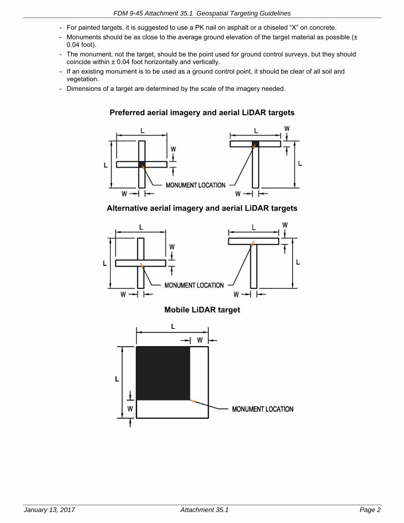
FDM 9-45 Attachment 35.1 Geospatial Targeting Guidelines
January 13, 2017 Attachment 35.1 Page 2
- For painted targets, it is suggested to use a PK nail on asphalt or a chiseled “X” on concrete.
- Monuments should be as close to the average ground elevation of the target material as possible (± 0.04 foot).
- The monument, not the target, should be the point used for ground control surveys, but they should coincide within ± 0.04 foot horizontally and vertically.
- If an existing monument is to be used as a ground control point, it should be clear of all soil and vegetation.
- Dimensions of a target are determined by the scale of the imagery needed.
Preferred aerial imagery and aerial LiDAR targets
Alternative aerial imagery and aerial LiDAR targets
Mobile LiDAR target

FDM 9-45 Attachment 35.1 Geospatial Targeting Guidelines
January 13, 2017 Attachment 35.1 Page 3
Acquisition Method Panel Length (L) Panel Width (W)
Aerial Imagery/LiDAR 1:2000, 1:3000 & 1:3600 5 ft 0.5 ft
Aerial Imagery 1:6000 10 ft 0.5 ft
Mobile LiDAR 1.5 ft 0.3 ft
Target Notes: - In wooded areas ‘L’ and ‘T’ legs increase to 10 ft for 1:2000, 1:3000 & 1:3600
- Place the control point precisely in the center of T and X for Aerial targets
- Use wood lath instead of metal pins to attach plastic targets to the ground
- Place the control point at the inside point of the chevron for mobile LiDAR targets as shown
- For mobile LiDAR targets, paint black background and then white paint.
Target shape - The “X” design is preferred for most aerial targets. It should be skewed 45 degrees when placed on an
existing line that will show on the imagery (e.g., a stripe painted on a roadway).
- The “T” design may be used where an “X” would not fit; e.g., at the edge of pavement. If the “T” must be placed in close proximity to the white line at the edge of pavement, the white line should be used as part of the target with fresh paint of the same width/length as the rest of the target.
Target Materials - Painted targets
- Painted targets must contrast with the surface upon which they are painted.
- Use white paint on asphalt or old (gray) concrete pavement.
- Use black paint on new (white) concrete pavement.
- Painted targets must have a contrasting center (painted legs with open center or center painted with contrasting color)
- Painted targets must be painted on a dry surface, swept free of dirt and sand.
Plastic targets - Plastic targets must contrast with the surrounding ground surface.
- Plastic targets must have a contrasting center (white plastic legs with open center or white plastic targets centered on a small piece of black plastic).
- The entire plastic target should be placed flush with the ground surface. If grass or other similar vegetation interferes it should be removed.
- Plastic targets must be tightly stretched and securely fastened down to prevent movement by the wind or passing animals. Use a sufficient number of fasteners to keep the plastic target legs in contact with the ground. Use wood lath instead of metal pins to attach plastic targets to the ground.
- Commercially available premade target sheets are not allowed.
The Photogrammetry staff tries to select target locations that are accessible and suitable for target placement. However, the Google Earth background imagery used for the target document may not show enough detail to avoid all circumstances such as flooding, construction, livestock or uncooperative landowners which may require an alternative target location.
In the example shown below, the designed target location for target T1 is in a flooded area. The target should be moved towards the center of the flight line along the model line to location OK1. The target location should not be moved more than 50 feet along the direction of flight as shown by target location BAD1.

FDM 9-45 Attachment 35.1 Geospatial Targeting Guidelines
January 13, 2017 Attachment 35.1 Page 4
If an existing target has been destroyed, or if a target needs to be moved more than 50’ from the designed location in any direction, please contact the Surveying & Mapping staff listed below to discuss alternative target locations:
Matt Bodden mobile: 608-235-4872 (preferred) or office: 608-246-5394
Bill Tredinnick: 608-246-7948
Cindy McCallum: 608-246-7944
Tiffany Novinska: 608-246-5397

FDM 9-45 Attachment 40.1 Naming Standards for WSI Files
January 13, 2017 Attachment 40.1 Page 1
Naming Standards for Wisconsin Summary Index (WSI) Files
The Region Survey Data Coordinator will provide ground control and map check data to the Surveying and Mapping Section using the Wisconsin Summary Index format. The names of these files shall adhere to the following format:
- The name of the WSI for Ground Control will contain the SY_ archival name_highway name_project ID_GC.wsi. If the project is in more than one county by more than 1000 feet than the ground control shall be submitted in each county and the three-letter abbreviation for the county should precede the GC.
Examples of two WSIs in Waukesha and Milwaukee counties, respectively:
2s164s100_I-43_1000-44-03_wak_GC.wsi
2s164s100_I-43_1000-44-03_mil_GC.wsi
Example of a WSI for a project that is only in one county:
8ironcthe_ush2_1180-00-05_GC.wsi
- The name of the WSI for Map Check will contain the SY_ archival name_highway name_project ID_MC.wsi. If the project is in more than one county by more than 1000’ then the ground control shall be submitted in each county and the three-letter abbreviation for the county should precede the MC.
Examples of map check WSI files in two counties for one project:
2s164s100_I-43_1000-44-03__wak_MC.wsi
2s164s100_I-43_1000-44-03__mil_MC.wsi
Example of a map check WSI file for a project that is in one county:
8ironcthe_ush2_1180-00-05_GC.wsi
- A Full WSI name will contain the SY_ archival name highway name_project ID_FULL.wsi. If the project is in more than one county by more than 1000’ then the ground control shall be submitted in each county and the three-letter abbreviation for the county should precede the FULL. This file contains ground control, corners and bench mark data.
Examples of Full WSI files in two counties for one project:
2s164s100_I-43_1000-44-03__wak_FULL.wsi
2s164s100_I-43_1000-44-03__mil_FULL.wsi
Example of Full WSI file for a project that is in one county:
8ironcthe_ush2_1180-00-05_FULL.wsi
- REV should be added to the front of the name of any WSI that has been revised.
Examples:
Rev_2s164s100_I-43_1000-44-03__wak_FULL.wsi
Rev_2s164s100_I-43_1000-44-03__mil_FULL.wsi
Rev_8ironcthe_ush2_1180-00-05_FULL.wsi
See FDM 9-45 Attachment 40.3 for the list of county zone numbers.

FDM 9-45 Attachment 40.2 Naming Standards for Folders and Files on the LiDAR Server
January 13, 2017 Attachment 40.2 Page 1
Naming Standards for Folders and Files on the LiDAR Server
A copy of the files and data for each LiDAR project shall be stored on the LiDAR Server maintained by the Photogrammetry Unit. The region may also have a copy on their local server to improve performance when using the data with appropriate software. The Region Survey Data Coordinator or Photogrammetry staff will copy the data to the server using the following conventions:
- There will only be six folders directly underneath the main LiDAR server designation:
SE, NE, NW, SW, NC and SURVMAP
- Each folder under these folders will begin with a letter to identify the kind of project:
r - roundabout
b - borrow pit
s - structure
c - corridor
i – intersection
a - area
- The next part of the folder name will include the primary highway name using: IH, USH, STH, or CTH.
- The third part of the folder name will be the project ID.
- The fourth part of the folder name for a structure shall include the structure number.
For example, r-USH41-11207072 is the folder name for a roundabout project on USH 41.
- The LiDAR_Metadata_template.txt file that is located on the server should be copied and filled out as is appropriate for the project.
- The absolute path name for the central LiDAR server is \\dotlidar1p\10LIDARDATA.
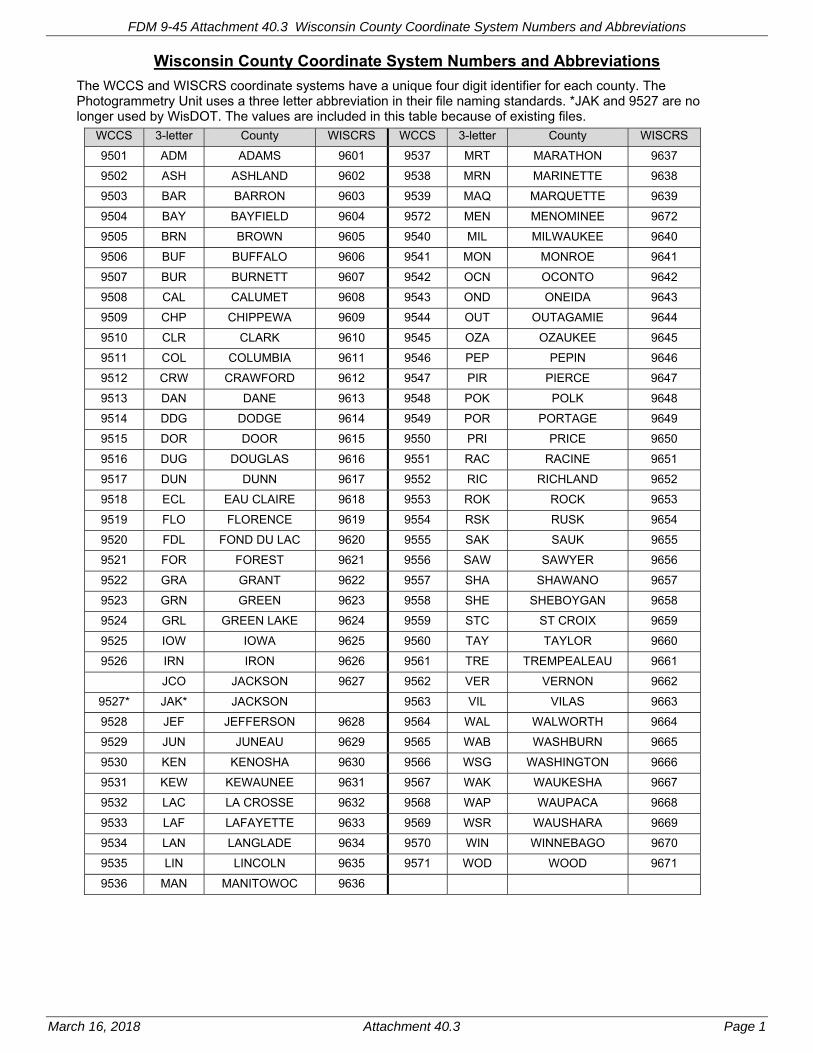
FDM 9-45 Attachment 40.3 Wisconsin County Coordinate System Numbers and Abbreviations
March 16, 2018 Attachment 40.3 Page 1
Wisconsin County Coordinate System Numbers and Abbreviations
The WCCS and WISCRS coordinate systems have a unique four digit identifier for each county. The Photogrammetry Unit uses a three letter abbreviation in their file naming standards. *JAK and 9527 are no longer used by WisDOT. The values are included in this table because of existing files.
WCCS 3-letter County WISCRS WCCS 3-letter County WISCRS
9501 ADM ADAMS 9601 9537 MRT MARATHON 9637
9502 ASH ASHLAND 9602 9538 MRN MARINETTE 9638
9503 BAR BARRON 9603 9539 MAQ MARQUETTE 9639
9504 BAY BAYFIELD 9604 9572 MEN MENOMINEE 9672
9505 BRN BROWN 9605 9540 MIL MILWAUKEE 9640
9506 BUF BUFFALO 9606 9541 MON MONROE 9641
9507 BUR BURNETT 9607 9542 OCN OCONTO 9642
9508 CAL CALUMET 9608 9543 OND ONEIDA 9643
9509 CHP CHIPPEWA 9609 9544 OUT OUTAGAMIE 9644
9510 CLR CLARK 9610 9545 OZA OZAUKEE 9645
9511 COL COLUMBIA 9611 9546 PEP PEPIN 9646
9512 CRW CRAWFORD 9612 9547 PIR PIERCE 9647
9513 DAN DANE 9613 9548 POK POLK 9648
9514 DDG DODGE 9614 9549 POR PORTAGE 9649
9515 DOR DOOR 9615 9550 PRI PRICE 9650
9516 DUG DOUGLAS 9616 9551 RAC RACINE 9651
9517 DUN DUNN 9617 9552 RIC RICHLAND 9652
9518 ECL EAU CLAIRE 9618 9553 ROK ROCK 9653
9519 FLO FLORENCE 9619 9554 RSK RUSK 9654
9520 FDL FOND DU LAC 9620 9555 SAK SAUK 9655
9521 FOR FOREST 9621 9556 SAW SAWYER 9656
9522 GRA GRANT 9622 9557 SHA SHAWANO 9657
9523 GRN GREEN 9623 9558 SHE SHEBOYGAN 9658
9524 GRL GREEN LAKE 9624 9559 STC ST CROIX 9659
9525 IOW IOWA 9625 9560 TAY TAYLOR 9660
9526 IRN IRON 9626 9561 TRE TREMPEALEAU 9661
JCO JACKSON 9627 9562 VER VERNON 9662
9527* JAK* JACKSON 9563 VIL VILAS 9663
9528 JEF JEFFERSON 9628 9564 WAL WALWORTH 9664
9529 JUN JUNEAU 9629 9565 WAB WASHBURN 9665
9530 KEN KENOSHA 9630 9566 WSG WASHINGTON 9666
9531 KEW KEWAUNEE 9631 9567 WAK WAUKESHA 9667
9532 LAC LA CROSSE 9632 9568 WAP WAUPACA 9668
9533 LAF LAFAYETTE 9633 9569 WSR WAUSHARA 9669
9534 LAN LANGLADE 9634 9570 WIN WINNEBAGO 9670
9535 LIN LINCOLN 9635 9571 WOD WOOD 9671
9536 MAN MANITOWOC 9636
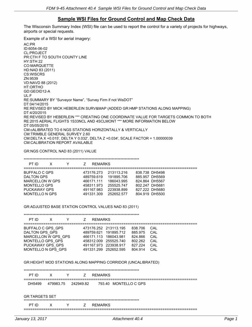
FDM 9-45 Attachment 40.4 Sample WSI Files for Ground Control and Map Check Data
January 13, 2017 Attachment 40.4 Page 1
Sample WSI Files for Ground Control and Map Check Data
The Wisconsin Summary Index (WSI) file can be used to report the control for a variety of projects for highways, airports or special requests.
Example of a WSI for aerial imagery: AC:PR ID:6054-06-02 CL:PROJECT PR:CTH F TO SOUTH COUNTY LINE HY:STH 22 CO:MARQUETTE HD:NAD 83 (2011) CS:WISCRS ZN:9539 VD:NAVD 88 (2012) HT:ORTHO GD:GEOID12-A UL:F RE:SUMMARY BY “Surveyor Name”, “Survey Firm if not WisDOT” DT:04/14/2015 RE:REVISED BY MICK HEBERLEIN SURV&MAP (ADDED GR:HMP STATIONS ALONG MAPPING) DT:4/20/2015 RE:REVISED BY HEBERLEIN *** CREATING ONE COORDINATE VALUE FOR TARGETS COMMON TO BOTH RE:2015 AERIAL FLIGHTS 1S33NCL AND 4SCLMONT *** MORE INFORMATION BELOW DT:05/05/2015 CM:cALIBRATED TO 6 NGS STATIONS HORIZONTALLY & VERTICALLY CM:TRIMBLE GENERAL SURVEY 2.60 CM:DELTA X +0.015', DELTA Y 0.032', DELTA Z +0.034', SCALE FACTOR = 1.00000039 CM:CALIBRATION REPORT AVAILABLE GR:NGS CONTROL NAD 83 (2011) VALUE ******************************************************************************** PT ID X Y Z REMARKS ================================================================================ BUFFALO C GPS 473176.273 213113.216 838.738 DH5498 DALTON GPS 489759.619 191895.706 885.957 DH5569 MARCELLON W GPS 466171.111 186043.995 824.864 DH5567 MONTELLO GPS 458311.973 255525.747 802.247 DH5681 PUCKAWAY GPS 491167.983 223938.899 827.222 DH5680 MONTELLO N GPS 491331.309 252652.577 804.919 DH5500 GR:ADJUSTED BASE STATION CONTROL VALUES NAD 83 (2011) ******************************************************************************** PT ID X Y Z REMARKS ================================================================================ BUFFALO C GPS_GPS 473176.252 213113.195 838.706 CAL DALTON GPS_GPS 489759.621 191895.712 885.975 CAL MARCELLON W GPS_GPS 466171.113 186043.981 824.866 CAL MONTELLO GPS_GPS 458312.009 255525.740 802.262 CAL PUCKAWAY GPS_GPS 491167.973 223938.917 827.224 CAL MONTELLO N GPS_GPS 491331.299 252652.595 804.914 CAL GR:HEIGHT MOD STATIONS ALONG MAPPING CORRIDOR (UNCALIBRATED) ******************************************************************************** PT ID X Y Z REMARKS ================================================================================ DH5499 479983.75 242949.82 793.40 MONTELLO C GPS GR:TARGETS SET ******************************************************************************** PT ID X Y Z REMARKS ================================================================================

FDM 9-45 Attachment 40.4 Sample WSI Files for Ground Control and Map Check Data
January 13, 2017 Attachment 40.4 Page 2
T102 480024.906 200926.450 833.024 TGT T103 481694.568 200823.433 868.877 TGT T201 472308.531 251469.758 803.056 TGT T202 472149.616 250140.742 832.453 TGT T203 473324.300 251160.077 804.848 TGT T255 474560.534 222178.332 826.108 XYZ Southeast corner of concrete T256 475419.576 222974.610 832.771 TGT CM:*** CREATING ONE COORDINATE VALUE FOR TARGETS COMMON TO BOTH 2015 AERIAL CM:FLIGHTS 1S33NCL AND 4SCLMONT *** CM:T104, T105 AND T108 OBSERVATIONS COMBINED WITH SW REGION FOR MAPPING VALUE. CM:T102 AND T103 WERE PICKED UP AFTER THE EARLY FLIGHT AND WERE PLACED BY CM:ANOTHER CONSULTANT PRIOR TO SECOND FLIGHT SO THERE ARE DIFFERENT POINTS FOR CM:EACH FLIGHT WITH SAME POINT NAME. CM:T102_NCR & T103_NCR APPEAR ONLY ON NORTH CENTRAL REGION FLIGHT. CM:T102_SWR & T103_SWR APPEAR ONLY ON SOUTHWEST REGION FLIGHT. CM:T101 (SW REGION) AND T293 (NC REGION) ARE THE SAME POINT AND OBSERVATIONS CM:COMBINED FOR COORDINATES BELOW. GR:POINTS AND COORDINATES USED FOR MAPPING ******************************************************************************** PT ID X Y Z REMARKS ================================================================================ T102_NCR 480024.906 200926.450 833.024 T102_SWR 480019.906 200926.124 833.211 T103_NCR 481694.568 200823.433 868.877 T103_SWR 481717.442 200825.249 869.539 T104 481589.093 199987.725 859.682 T105 480036.398 199967.947 842.911 T108 480743.584 198173.520 883.349 T293 481453.394 201766.752 851.300 T101 SW REGION PROJ Example of a WSI for airport project AC:PR ID:0722-65-02 CL:PROJECT PR:LANCASTER MUNICIPAL AIRPORT HY:STH.61 CO:GRANT HD:NAD 83 (2007) CS:WCCS ZN:9522 VD:NAVD 88 (2007) HT:ORTHO UL:F VR:TRIMBLE GEOMATICS OUTPUT RE:SUMMARY BY MICK HEBERLEIN SURV&MAP DT:05/09/2008 RE:REVISED BY DT:00/00/99 GR:BASE STATION CONTROL ******************************************************************************** PT ID X Y Z REMARKS ================================================================================ H093 825199.582 516284.213 1087.20 LANCASTER GPS 73C A 826767.703 500499.016 1014.23 LANC AP PAC 73C B 827906.159 497839.384 1021.20 LANC AP SAC GR:TARGETED POINTS ******************************************************************************** PT ID X Y Z REMARKS ================================================================================ T101 823221.990 505770.183 1040.970 TGT T102 825037.861 505756.108 1052.868 TGT T103 826604.522 505746.996 1057.380 TGT

FDM 9-45 Attachment 40.4 Sample WSI Files for Ground Control and Map Check Data
January 13, 2017 Attachment 40.4 Page 3
T104 827739.954 503125.333 1036.435 TGT T105 826456.833 502111.097 1007.354 TGT T106 823826.259 500486.420 995.920 TGT T107 829424.828 499346.793 1017.615 TGT T108 825250.878 497810.738 1011.583 TGT T109 827499.359 497812.055 1013.881 TGT T110 831106.752 495473.291 1002.554 TGT T111 829339.990 495153.212 1009.500 TGT T112 826732.791 493873.696 978.698 TGT GR:HORIZONTAL COORDINATES ESTABLISHED ******************************************************************************** PT ID X Y Z REMARKS ================================================================================ 1S08 826430.621 505457.935 XY GR:CONTROL POINTS CHECKED ******************************************************************************** PT ID X Y Z REMARKS ================================================================================ 1S08 1063.54 73C C 826735.606 501596.030 1014.6 DH5302 844773.884 507104.302 857.2 ELLENBORO C GPS Example of a WSI for special request (Truax network) AC:PR ID:0656-24-00 CL:PROJECT PR:TRUAX LAB NETWORK HY:STH ## CO:DANE HD:NAD 83 (2007) CS:WCCS (MOL) ZN:9513 VD:NAVD 88 (2007) HT:ORTHO GD:GEOID09 UL:F VR:TRIMBLE GEOMATICS OUTPUT RE:SUMMARY BY MICK HEBERLEIN SURV&MAPPING DT:07/29/2011 RE:REVISED BY DT:00/00/99 CM:ELEVATIONS ARE FROM LEVEL LOOP RUN BY SW REGION MADISON CM:RTK ELEVS BASED ON 3 POINT VERTICAL CALIBRATION USING POINTS BELOW CM:NO HORIZONTAL CALIBRATION DONE GR:POINTS ******************************************************************************** PT ID X Y Z REMARKS ================================================================================ D101 835628.876 501711.101 859.385 CHSL X CM: RTK ELEV D101 859.370 E102 835546.407 501693.685 859.525 HUB CM: RTK ELEV E102 859.455 A103 835631.201 501534.856 858.957 CHSL X CM: RTK ELEV A103 858.893 H104 835547.086 501534.137 858.625 CHSL X CM: RTK ELEV H104 858.604 B105 835722.158 501456.897 859.697 HUB CM: RTK ELEV B105 859.654 F106 835480.530 501473.831 858.510 HUB CM: RTK ELEV F106 858.464 C107 835618.746 501400.157 858.169 CHSL X CM: RTK ELEV C107 858.114

FDM 9-45 Attachment 40.4 Sample WSI Files for Ground Control and Map Check Data
January 13, 2017 Attachment 40.4 Page 4
G108 835529.514 501397.487 858.349 HUB CM: RTK ELEV G108 858.285 GR:CONTROL POINTS USED ******************************************************************************** PT ID X Y Z REMARKS ================================================================================ BURKE S GPS 838538.994 496212.572 851.258 BURKE SO M 838538.960 496212.559 851.258 V107 M 835065.485 492998.420 855.691 V 107 835112.172 492878.142 855.691 2V04 836954.752 503410.161 869.585 2V04 M 836969.158 503578.688 869.585 CM:POINTS WITH M ARE THE MEASURED RESULT AFTER CALIBRATION CM:OTHERWISE, PUBLISHED CONTROL POINT VALUE.
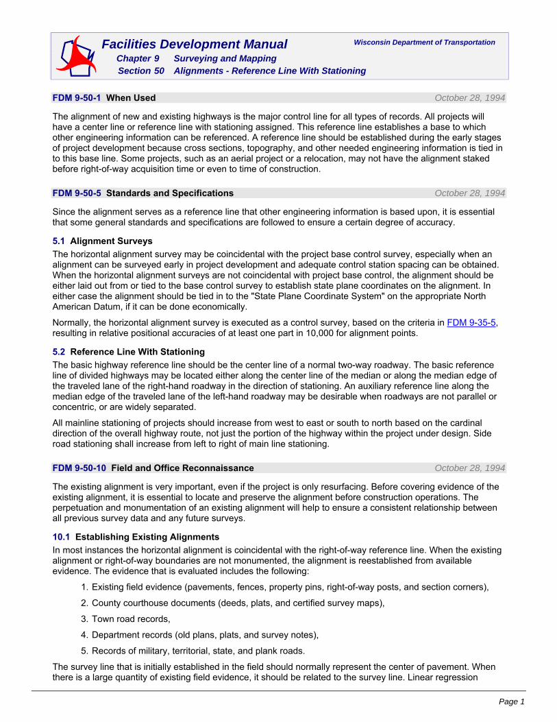
Page 1
Facilities Development Manual Wisconsin Department of Transportation Chapter 9 Surveying and Mapping Section 50 Alignments - Reference Line With Stationing
FDM 9-50-1 When Used October 28, 1994
The alignment of new and existing highways is the major control line for all types of records. All projects will have a center line or reference line with stationing assigned. This reference line establishes a base to which other engineering information can be referenced. A reference line should be established during the early stages of project development because cross sections, topography, and other needed engineering information is tied in to this base line. Some projects, such as an aerial project or a relocation, may not have the alignment staked before right-of-way acquisition time or even to time of construction.
FDM 9-50-5 Standards and Specifications October 28, 1994
Since the alignment serves as a reference line that other engineering information is based upon, it is essential that some general standards and specifications are followed to ensure a certain degree of accuracy.
5.1 Alignment Surveys
The horizontal alignment survey may be coincidental with the project base control survey, especially when an alignment can be surveyed early in project development and adequate control station spacing can be obtained. When the horizontal alignment surveys are not coincidental with project base control, the alignment should be either laid out from or tied to the base control survey to establish state plane coordinates on the alignment. In either case the alignment should be tied in to the "State Plane Coordinate System" on the appropriate North American Datum, if it can be done economically.
Normally, the horizontal alignment survey is executed as a control survey, based on the criteria in FDM 9-35-5, resulting in relative positional accuracies of at least one part in 10,000 for alignment points.
5.2 Reference Line With Stationing
The basic highway reference line should be the center line of a normal two-way roadway. The basic reference line of divided highways may be located either along the center line of the median or along the median edge of the traveled lane of the right-hand roadway in the direction of stationing. An auxiliary reference line along the median edge of the traveled lane of the left-hand roadway may be desirable when roadways are not parallel or concentric, or are widely separated.
All mainline stationing of projects should increase from west to east or south to north based on the cardinal direction of the overall highway route, not just the portion of the highway within the project under design. Side road stationing shall increase from left to right of main line stationing.
FDM 9-50-10 Field and Office Reconnaissance October 28, 1994
The existing alignment is very important, even if the project is only resurfacing. Before covering evidence of the existing alignment, it is essential to locate and preserve the alignment before construction operations. The perpetuation and monumentation of an existing alignment will help to ensure a consistent relationship between all previous survey data and any future surveys.
10.1 Establishing Existing Alignments
In most instances the horizontal alignment is coincidental with the right-of-way reference line. When the existing alignment or right-of-way boundaries are not monumented, the alignment is reestablished from available evidence. The evidence that is evaluated includes the following:
1. Existing field evidence (pavements, fences, property pins, right-of-way posts, and section corners),
2. County courthouse documents (deeds, plats, and certified survey maps),
3. Town road records,
4. Department records (old plans, plats, and survey notes),
5. Records of military, territorial, state, and plank roads.
The survey line that is initially established in the field should normally represent the center of pavement. When there is a large quantity of existing field evidence, it should be related to the survey line. Linear regression

FDM 9-50 Alignments - Reference Line With Stationing
Page 2
analysis can then be used to evaluate the data and arrive at a center line definition that best fits existing field conditions. In these cases the analysis is usually done in the office. After a complete analysis has been performed, the line can be adjusted, if necessary.
10.2 References
The records of early roads in Wisconsin can be obtained from the State Historical Society. The records on file cover the period from 1835-1886. Reprinted below are their file locator number and a brief description as contained on the locator cards:
1. Series 234 (2/3/3-28): Records of surveys of state roads as laid out and established by the state Legislature, showing direction of courses, town and range locations, distances, bearing trees, map sketches, explanations, certifications of commissioners, their signatures, and names of surveyors. Volume 4 contains an index of the surveys and is arranged alphabetically by the name of the location of the origin of the road.
2. Series 235 (2/3/3-30): Plats and field notes of surveys for state roads, giving date, signature of surveyor, signatures of commissioners appointed to lay out the road, date filed with the Secretary of State, and his signature. The plats also show the page number on which they registered in the Record of State Roads. Alphabetically arranged by name of road.
The names of the early roads can be obtained from "A History of Wisconsin Highway Development, 1835-1945," State Highway Commission of Wisconsin, 1947.
FDM 9-50-15 Field Procedures October 28, 1994
15.1 Establishing Existing Alignments
After all available evidence of an existing alignment has been gathered, a field survey crew can then begin to re-establish the alignment in the field. The surveyor should pull the recorded distances obtained from all the available evidence such as: section corners, property corners, fences, and right of way points and mark this location with a temporary monument. These points should then be compared with points obtained from splitting pavements, structures and fences.
When splitting pavements care should be taken to avoid areas where widening may have taken place on one side only. In areas where concrete pavement is known to exist under an overlay, and reflection cracks are not visible, it may be advantageous to expose the concrete pavement in spot locations to aid in the determination of the centerline.
The existing curve information may be determined by several different methods: measuring the PI angle and either the external distance, tangent, long chord, or curve length. Try to avoid putting in small unintentional PI points that may have been created by pavement wander.
When re-establishing PI monuments that cannot be recovered, it is the surveyor's responsibility to restore the monuments as near as possible to their original positions. Re-establishment should be based on a thorough analysis of the existing evidence before replacing the missing monument. The re-established PI will usually result in a new slightly different intersecting angle. Generally when this occurs, use the original degree of curve and compute new curve data. However, certain conditions may exist that will require holding the original tangent distances, and recomputation of a new degree of curve and curve data may be necessary. There may be differences between the old and new tangent distances and, in order to maintain the original stationing, equations may be necessary to reflect these differences.
When all information has been evaluated, including comparison to as built plan, if available, a final determination of the alignment can be made. If the alignment is to be tied into the primary control survey, it should be done at this time to allow final adjustment of distances and angles. This will help to avoid small equations in alignment by the adjustment program. When the final adjustment is complete, the survey crew can proceed to stake the alignment in the field with stationing. Stationing in rural areas would normally be every 25 meters (100 feet) and in urban areas every 50 feet or 20 meters, including all PC's, PI's, PT's, and POT's where accessible.
15.2 New Alignments
New alignments to be staked in the field are most often done with a total station instrument linked to a data collector. The surveyor should be provided with a horizontal coordinate listing of all pertinent points, with stationing, to define the alignment. The alignment points should be referenced to the primary control survey to facilitate ease of layout in the field.

FDM 9-50 Alignments - Reference Line With Stationing
Page 3
FDM 9-50-20 Alignment Computation October 28, 1994
Essentially, there are two methods for defining horizontal alignments. An alignment may be established in the field by conventional survey or an alignment may be established in the office by computational procedures (paper alignments). Combinations of these two methods may also be used to define a horizontal alignment. Except in those cases where control surveys are not required (see FDM 9-1-5), the coordinates of the PCs, PTs, PIs, and POTs are computed and used to describe the alignments.
20.1 Field-Surveyed Alignments
Field-surveyed alignments may be established by design controls, such as a distance from a building, or by reestablishing an existing center line of pavement. Once the alignment has been established, control surveys are run to establish coordinates for curve points and points on tangent.
Usually the points of intersection of the tangents (PI's) will be included in a traverse network. After the traverse network has been adjusted and coordinates for the PI's have been determined, the coordinates of the intermediate POTs should be computed.
Attachment 20.1 illustrates the adjustment of an intermediate POT. In Attachment 20.1, points one and three are PI's on an alignment. The coordinates for these points are computed as part of a traverse network adjustment. The distance between point one and three was not measured directly because of the terrain, but was measured indirectly by measuring from point two to one and from two to three. The total distance between points one and three (C) is adjusted during the network computations used to define points one and three. Consequently, distance A and B should be adjusted in the proportion they bear to the total distance (C) before defining point two. The use of the "compass rule" adjustment procedure in COGO when applied to straight lines with intermediate points will result in a proportional adjustment of the individual segments.
20.2 Alignments Established by Design Computation
Design-computed alignments occur most times when using photogrammetrically prepared mapping. With field-surveyed alignments, the first precise definition of the alignment occurs when the point is set in the field even though coordinates are computed later. With design-computed alignments, the first precise definition of the alignment occurs when the coordinates are computed or scaled from maps. The points are then established in the field at the predetermined coordinate position. When an alignment is to be defined by design computation, an attempt should be made to establish project base control survey stations near where the alignment PIs will be located, provided design requirements of the base control layout can be met. This will facilitate economical and accurate layout of the alignment at a later date.
Design computations should include layout information to enable survey crews to establish the alignment in the field. Ideally, these computations will include coordinate information, angles and distances from project base control stations to nearby PIs, PCs, PTs, POTs, and other selected points on the alignment. The computations should also include curve layout information and offsets to other alignments.
Once the points defining an alignment have been set at their predetermined coordinate position, the line between points is established by conventional field survey procedures.
20.3 Elements Common to All Alignments
Regardless of the method used to initially define an alignment, additional computations are required in order to provide a comprehensive data base for project development. In addition to the coordinates and curves defining the alignment, the following should be computed:
1. Station values for all alignment points
2. Intersection of section lines with the alignment, and the resulting station and the distance and bearing to section corners
3. Intersection with other alignments, such as side roads, and station equation and angle of intersection
4. Coordinates of property markers recovered during right-of-way surveys.
These computations can be carried out within one problem run for most projects. COGO has provisions for saving the information on a computer file for future retrieval, allowing for additional computations.
20.4 Data Storage
Alignment information should be put into an ICES COGO, CEAL, CAiCE, or other comparable computer program for future retrieval, allowing for additional computations. All other field notes and documents shall be put in the survey folder for that project.

FDM 9-50 Alignments - Reference Line With Stationing
Page 4
LIST OF ATTACHMENTS
Attachment 20.1 Adjustment of Intermediate POT
FDM 9-50-25 Monumentation Required October 28, 1994
When dealing with the establishment of an existing alignment you may want to use temporary monuments such as spikes or paint marks, until the final alignment has been determined. Try to avoid using type 2 or 3 monuments, such as PK nails, which could later be confused with the final alignment monuments.
The final alignment should be monumented with type 2 or type 3 monuments on all PCs, PIs, PTs, POTs, side road intersections, and other pertinent points. Points needing to be referenced should have at least three reference ties. The final alignment should be tied into the primary control if applicable.

FDM 9-50 Attachment 20.1 Adjustment of Intermediate POT
October 28, 1994 Attachment 20.1 Page 1
Where:
A & B = Measured Distance
C = A + B
= Correction to C due to Traverse Adjustment
Then:
A adjusted = A + * A
C
B adjusted = B + * B
C
C
A B
1 2 3

Page 1
Facilities Development Manual Wisconsin Department of Transportation Chapter 9 Surveying and Mapping Section 55 Drainage Structure Surveys
FDM 9-55-1 Introduction October 28, 1994
1.1 When Used
Whenever replacing or installing a bridge or box culvert involving the movement of water, hydraulic information is required. For Rehabilitation and Separation Structures, see Section 60 of this manual.
1.2 Data Collected
In general, drainage survey notes and mapping shall indicate the location and elevation on ditches, waterways, culvert outlets, tile lines, catch basins, manholes, existing structures, underground facilities, overhead facilities, trees etc.
1.3 Standards and Specifications
The specifications, standards and datums for all structure surveys shall conform to Section 35, Horizontal Control - Traverse and Section 40, Vertical Control.
1.4 Coordination
Coordinate all work that involves drainage regions with the County drainage boards of that region. The legal procedures for these cases are set forth in Chapter 86.075, 88.87 and 88.89 of state statutes (see FDM 5-15).
FDM 9-55-5 Field Procedures October 28, 1994
5.1 Horizontal Alignment
Recover existing, or establish proposed, reference line and station for a minimum of 300 meters each side of the proposed site. The surveyor must locate by angle and stationing or coordinates all base lines that will be used for additional information, such as base line for stream channel cross sections (see Attachment 5.1).
5.2 Topography
Topography should include features within 150 meters of the site, at least to right of way width and 100 meters upstream and downstream along the stream bed. Locate all existing structure features including any auxiliary structure, utilities, curb and gutter, tile lines, drainage ditches, intersecting stream, island, old piers or footings, trees, building within the flood plain, banks of the stream, boat landings, etc. Record the type of vegetation in flood plain area. Contact Diggers Hotline far enough in advance to have all underground utilities located.
5.3 Profile
Profiles are required on the reference line of roadway for 300 meters each side of site. The profile at the stream bed and water surface profile should be established at the site, 150, 300, and 450 meters up and down stream. Additional profiles should be taken at any other spot that appears to be irregular, such as rapids, riffles, or stream bed scour. Any part of the roadway that would be below high water in an overflow section requires profiles. Although, not required for the structure survey report, the roadway designer will need topography and cross sections in the area of any overflow sections. Measure stream profiles along the thread of channel.
5.4 Cross Sections/DTMs
Cross sections or DTM's should be taken a minimum of 150 meters on each side of the structure along the reference line of the roadway, as well as a minimum of 100 meters on each side of the structure up and down the stream channel, with additional sections around the abutment ends to properly show shape and ends of fill area. The roadway cross section increment is usually 40 meters in rural areas and 20 meters in urban areas.
Sections up and down the stream channel can be taken from a base line or by random shots. The end result should be the capability to plot a contour map or Digital Terrain Model (DTM) of the area.
Take flood plain sections upstream and downstream from the site. The desired location of the area should be the distance of the span length measured from either edge of the structure. The cross sections should extend to a point that is above high water elevation and be taken in a representative reach of the natural channel, normal to stream flow at flood stage. See the drawing in Attachment 5.2.
Also, obtain elevations at the entrances of all buildings in the flood plain. This information can be supplemented

FDM 9-55 Drainage Structure Surveys
Page 2
by photogrammetric methods.
5.5 Existing Structure Information
Measure waterway openings at upstream, downstream and at site structure. Measure waterway areas in square feet (square meters) below high water and at 90 degrees to direction of flow. Obtain low (steel/concrete) elevations, deck elevations, top of rail or curb elevations, water on date of survey, high water elevations and any overflow areas at all structure sites. If possible, obtain high water elevations upstream and downstream (see Attachment 5.3).
The source of high water information can be local residents, county patrolmen, region bridge maintenance section or visible evidence. The field notes should identify the source, cause, and date of high water.
The same vertical datum must be used for all structures within 800 meters of the site. Check area between upstream and site structure for additional drainage contributing to flow at site, such as culverts and tributaries. Get dimensions, if applicable.
Take photos of all structures involved and any buildings within 50 meters of the site. Take a panoramic view looking upstream and downstream from the proposed site.
LIST OF ATTACHMENTS
Attachment 5.1 Horizontal Alignment at Drainage Structure
Attachment 5.2 Flood Plain Section at Drainage Structure
Attachment 5.3 Waterway Opening at Drainage Structure
FDM 9-55-10 Computations October 28, 1994
The hydraulic computations for bridges and box culverts that are designed by WisDOT staff are computed by the Office of Design. The region must provide the following computations:
1. Reduction of all field notes,
2. Vertical alignment including X-section or DTM data,
3. Horizontal alignment,
4. Waterway areas at the site,
5. Waterway areas of upstream and downstream structure,
6. Contour map,
7. Electronic files if applicable.
In addition, the region should complete the structure survey report forms with information from the field survey. See Chapter 6 of the Bridge Manual for more guidance on structure survey reports. Include a request for special navigational clearance, if applicable.
FDM 9-55-15 Monumentation Required October 28, 1994
The Highway Reference Line shall have a minimum of two, Type 2 or 3, monuments at the structure site. These points should be referenced by swing ties and, in some cases, tied to the Wisconsin High Precision Geodetic Network (WHPGN).
Bench marks should be set at the site with at least one bench mark on each side of the structure. These should be tied to the National Geodetic Vertical Datum of 1929 (NAVD 29) or to the North American Vertical Datum of 1988 (NAVD 88).

FDM 9-55 Attachment 5.1 Horizontal Alignment at Drainage Structure
October 28, 1994 Attachment 5.1 Page 1
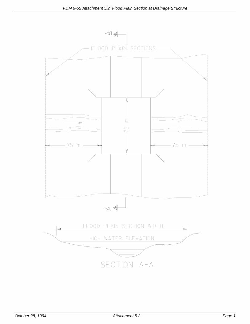
FDM 9-55 Attachment 5.2 Flood Plain Section at Drainage Structure
October 28, 1994 Attachment 5.2 Page 1

FDM 9-55 Attachment 5.3 Waterway Opening at Drainage Structure
October 28, 1994 Attachment 5.3 Page 1

Page 1
Facilities Development Manual Wisconsin Department of Transportation Chapter 9 Surveying and Mapping Section 60 Structure Surveys
FDM 9-60-1 Introduction October 28, 1994
1.1 When Used
This section covers both Separation Structure Surveys and Rehabilitation Structure Surveys. These surveys are used in connection with both new structures and the repair of existing structures. For details on structures requiring hydraulic information, please refer to Section 55.
1.2 Standards and Specifications
For guidance on the specifications, standards and datums used for structure surveys, refer to Section 35, Horizontal Control - Traverse, and Section 40, Vertical Control.
1.3 References
See the Bridge Manual Chapter 6 for detailed guidance on structure surveys.
FDM 9-60-5 Field Procedures October 28, 1994
5.1 Separation Structure Survey
Before conducting field operations, refer to Chapter 6 of the Bridge Manual for more guidance on Separation Structure Survey Reports. A separation structure survey will require the establishment of the alignment approximately 300 meters in each direction from the site. If an old plan exists with the proper cardinal direction of stationing, the surveyor should use that stationing or convert it to metric as necessary. At railroad crossings, an attempt should be made to establish railroad stationing. The surveyor should also establish and record the intersection stationing and angle of intersection or coordinates between the reference lines.
Profile the reference lines 300 meters minimum in all directions. Separation structure surveys require cross sections or DTM's a minimum of 90 meters along all reference lines. Topography should include all features within a minimum 90-meter radius of the site. Contact Diggers Hot Line in advance for underground utility locations. Photographs are required of the existing structure and all buildings within 50 meters of the site. The scope of survey data will depend on project needs, if in doubt, discuss the project with the designer.
5.2 Rehabilitation Structure Survey
Rehabilitation structure reference lines are established by splitting the structure and using old plan stationing, if available. If old stationing is not available, assign a station to the end of the deck or centerline and extend the stationing 90 meters minimum beyond the ends of deck. The cross sections normal to the reference line shall be taken from both ends of the deck for 90 meters at intervals of 3 meters for the first 30 meters and at 15 meter intervals thereafter. The cross sections should be taken out to shoulder width, and include shots at the centerline, edge of lanes and gutters, if they exist.
On structures less than 30 meters in length, sections of the deck are required every 3 meters and at every construction joint. On structures over 30 meters in length, the cross-section interval can be increased up to 10 meters. If in doubt on the cross-section intervals, check with the Office of Design. See Attachment 5.1 for a schematic of the scope of survey data for Rehabilitation Structure Surveys.
Beam seat elevations should be determined at each exterior girder, and at all substructure units. Drain elevations should also be determined. Measure joint openings at both the top and bottom of the deck, if accessible. Separate measurements should be taken at the centerline of roadway and at flow lines. Record the temperature and date of the measurement. Measure the clearance between the girder ends at the piers and the front face of the back wall at abutments.
Record the location of deck construction joints and the location and elevation of bench marks. The records must show and identify what was used as the basis of stationing on the structure. See Attachment 5.2 for a detailed schematic of structure terminology and joint openings etc.
LIST OF ATTACHMENTS
Attachment 5.1 Survey Data for Structure Rehabilitation Project
Attachment 5.2 Structure Terminology Diagram

FDM 9-60 Structure Surveys
Page 2
FDM 9-60-10 Monumentation Required October 28, 1994
10.1 Separation Structure Survey
Separation Structure Surveys shall have at least three horizontal, Type 2 or Type 3, monuments on each reference line, including one at the point of intersection. A minimum of two bench marks shall be set.
10.2 Rehabilitation Structure Survey
A structure rehabilitation survey may use the center of structure span or deck end to establish stationing. A PK nail in the centerline of joint or a chiseled 'x' with assigned stationing will suffice. Use known elevations if there is a bench mark disc in the structure or a known elevation nearby. If there are no established bench marks in the area, a temporary bench mark may be chiseled in a wingwall or abutment and assigned an arbitrary elevation.

FDM 9-60 Attachment 5.1 Survey Data for Structure Rehabilitation Project
October 28, 1994 Attachment 5.1 Page 1

FDM 9-60 Attachment 5.2 Structure Terminology Diagram
October 28, 1994 Attachment 5.2 Page 1

Page 1
Facilities Development Manual Wisconsin Department of Transportation Chapter 9 Surveying and Mapping Section 65 Cross Sections/Digital Terrain Models (DTMs)
FDM 9-65-1 Introduction October 28, 1994
1.1 When Used
Projects that need earth volume quantities, profiles, drainage information, or other elevation dependant views for original design and final quantities will employ either cross sections or digital terrain models (DTMs). Cross sectioning is the process of determining elevations of the ground along lines at right angles to a reference line.
A digital terrain model (DTM) is a mathematical model of the earth's surface. Three dimensional coordinates (X,Y,Z) of ground points are obtained by field surveying or photogrammetrically digitizing the points. By connecting the coordinates of these ground points with its closest "neighbor," a triangulated irregular network (TIN) is developed. Software then interpolates this TIN to generate contours, cross sections, and volumetric computations.
1.2 Standards and Specifications
The end product of cross sections or DTMs, whether by field or photogrammetric methods, is a plot of the original ground surface. The minimum accuracy of cross sections and DTMs is plus or minus 0.3 feet (90 mm) of the true ground elevation for final plans. DTMs may also be created for corridor studies but to a lesser accuracy. The proposed scope of the improvement and the character of the terrain will determine the width of the cross section of DTM.
FDM 9-65-5 Field Procedures October 28, 1994
5.1 Cross Sections
Cross sections, either aerial or field derived, are produced by determining ground elevations at breaklines along a line that is at right angles to the reference line. Typically, the project manager will specify the interval and width of cross sections. Normal field procedure is to take a cross section at 100 foot (40 m) intervals in rural areas and 50 feet (20 m) in urban areas. The field crew should also take special sections at sudden changes in terrain, private entrances, existing drainage facilities, and drainage scales for cross drains. These drainage sections may be skewed, if necessary, to follow the bottom of the drainage channel. All such sections should be noted on the cross section notes.
5.2 Digital Terrain Models (DTMs)
Whether using field or aerial methods, the objective is to acquire sufficient three dimensional coordinates (X,Y,Z) of ground points throughout the project area. Ample ground coordinates will ensure a cross section can be developed at any location desired. Within areas of possible relocation of center line, additional widespread coverage may be needed. Three dimensional coordinates need to be determined on all lines of discontinuity and at random locations, generally not exceeding 25 foot (10 meter) spacings. In flat or even slope terrain the spacings may be increased, but use an occasional check shot to make sure of an even slope. Through the use of DTMs and an engineering work station, the designer will have the flexibility to change center line locations and obtain new cross sections wherever necessary.
Although DTMs are desirable, they take approximately 30% more effort to create compared with normal cross sections. Therefore, their use should be confined to projects, or portions of projects, for which the preferred alignment has not been established. When requesting DTMs on a particular portion of a project, the project manager should define these areas by marking the limits on a mosaic or like exhibit. When splitting a project between normal cross sections and DTMs it is advisable to request DTM areas first due to the time factor. Also, the designer can be resolving the DTM area for final alignment while the remainder of the cross sections are being produced.
DTMs for final plan cross sections should not be generated from normal cross section data. Although each shot may be accurate, there is generally 100 feet (40 meters) between each section and significant elevation changes could occur within that distance which would result in inaccurate DTMs and subsequent cross sections.
When accurate elevations cannot be determined photogrammetrically because of dense vegetation, a polygon will be used to identify an obscured area. Points inside this polygon are then coded "OBS," for obscure area, in the ASCII file that is turned over to the project manager. If an obscured area is in a critical zone, a field survey crew should supplement the data with field shots to ensure reliable results from the DTM. When doing a field

FDM 9-65 Cross Sections/Digital Terrain Models (DTMs)
Page 2
DTM, the project manager should use some sort of grid layout to assure complete coverage of the area desired.
5.3 Computations
Cross section notes taken by hand need to be adjusted and elevations computed. Information gathered radially by total station and data collector will need to be computed and adjusted to the appropriate coordinated system.
FDM 9-65-10 Monumentation Required October 28, 1994
For horizontal locations, cross Sections will be tied to a survey reference line (see FDM 9-50-5). DTMs will be tied to a project coordinate system for horizontal location.
In most cases, project bench marks will establish vertical control. Some Resurface and Recondition 1 projects may not require a vertical datum if only typical sections and quantity computations are necessary.

Page 1
Facilities Development Manual Wisconsin Department of Transportation Chapter 9 Surveying and Mapping Section 70 Topography
FDM 9-70-1 Introduction October 28, 1994
1.1 When Used
WisDOT currently uses topography surveys to determine the position of natural and fabricated features along the survey route. Several different methods are used to obtain this data: station and offset left or right to a survey alignment or baseline, aerial mapping, or collecting data radially based on a coordinate system.
1.2 Standards and Specifications
Specifications, standards, and datums shall conform to Section 40, Vertical Control when determining elevations along with horizontal positioning, and to Section 35, Horizontal Control. Measurement of topography is usually to the nearest one foot (300 mm). However, measurements to the nearest tenth of a foot (30 mm) may be necessary to objects when it is not clear if they occupy existing right of way or encroach upon landmarks.
1.3 Other References
There is a certain amount of ground survey work involved in control and checking of photogrammetric methods. These procedures are covered in Section 45, Aerial Projects.
Sources of information for supplementing the survey include the following:
1. Region survey files
2. As built plans
3. Private and county surveyors
4. Municipalities
5. Railroads
6. Utility companies
FDM 9-70-5 Field Procedures October 28, 1994
Topographic features located by the station and offset method are normally expressed as a station value (plus) and an offset distance (out). The offset distance is always perpendicular to the survey reference line. When using radial topography methods, topographic features will be relative to a coordinate system for the project.
The surveyor shall identify all natural and fabricated features with sufficient accuracy to ensure contract quantity computation and production of planimetric drawings that accurately portray these features in relationship to each another. If natural or fabricated features impose a constraint on the design of a project or are an encroachment on an existing facility, conduct measurements more accurately. The measurement of most objects will be taken to the front or point nearest the alignment. Possible exceptions are right of way posts and utility poles; measure these to the back edge. When surveying to round manholes, measure to the center of casting. For curb inlets, use the flow line of the curb. When surveying existing pipes or larger drainage structures, indicate the size, type, condition, and total length of pipe or drainage structure.
Record the location of all bench marks and soil borings. Take extra care to accurately locate underground features such as wells, septic systems, and utility installations. The location of underground utilities should be established by coordination with Diggers Hotline, utility companies, and local government units.
When locating storm sewers, sanitary sewers, and water mains, coordinate efforts with the municipality or drainage region. They can provide plans and assistance, which will make the task much easier.
The region designer will specify the width of the project and topographic information is obtained for the entire length of the project to the width specified by the region designer or survey supervisor. The width is based on the proposed scope of the improvement and character of the terrain. Additional width may be obtained from aerial mapping.
Survey crew chiefs and other personnel who record field notes should become familiar with and use the conventional symbols and standard abbreviations contained in Chapter 15 of this manual. Notes taken electronically shall conform to the SDMS format.

FDM 9-70 Topography
Page 2
5.1 Computations
When working with a survey alignment, the line bearings and curve information will be required. When collecting data radially with a coordinate system it shall conform to the SDMS format so post processing can easily be carried out. You will need the horizontal and vertical data for control points when using the radial method.
5.2 Field Notes
It shall be a policy for the crew chief to scan the field notes for completeness. In the case of electronic data collection, the final plot should be reviewed by the crew chief for accuracy.
FDM 9-70-10 Data Destination, Formats, ETC. October 28, 1994
Field notes will be compiled and entered into the survey folder for each particular project. The survey folder should be forwarded to the survey supervisor and/or survey coordinator who will check for completeness and will either file the survey folder or forward to the design engineer.
Data collected by electronic data collector shall be downloaded to a personal computer for processing. This information will then be stored on a diskette and stored in the survey folder or other appropriate location. A hard copy should be printed out for the region files and the design engineer. The processed data will then be transferred to the appropriate unit/designer for plotting/processing.

Page 1
Facilities Development Manual Wisconsin Department of Transportation Chapter 9 Surveying and Mapping Section 75 Right-of-Way
FDM 9-75-1 Introduction December 21, 2010
1.1 When Used
Right-of-way surveys include surveys to establish and monument new right-of-way boundary lines and/or to establish or reestablish existing right-of-way reference line monumentation. The marking of existing right-of-way points where monumentation has been disturbed or destroyed shall follow FDM 9-5-5 and FDM 9-50-10.
Temporary right-of-way points are established on a project where the location of points may be subject to change during negotiation or when a point is in a field (cultivated area) that may be cropped before acquisition.
Permanent right-of-way is usually staked after acquisition. Permanent markers are also reset on completed projects where original markers have been disturbed or destroyed.
1.2 Standards and Specifications
For temporary right-of-way points that are going to be used only for appraisal and acquisition purposes, the accuracy can be ± 0.5 feet except in cases of a fixed object such as a well, septic tank, utility structure, etc., being in close proximity of the right-of-way boundary line. In this case a location should be established with a positional accuracy of at least 1:3,000; methods used shall be capable of producing a positional accuracy of at least 1:10,000.
Permanent monumentation shall be placed to ensure relative positional accuracy of at least 1:3,000; methods used shall be capable of producing a positional accuracy of at least 1:10,000.
FDM 9-75-5 Field Procedures December 21, 2010
5.1 Methods
The monumentation of right-of-way points can be done by station offset, radial methods, or coordinates. The station offset would be most useful for replacing old right-of-way monuments and when staking for appraisal purposes when the reference line has been previously established.
When staking for appraisal the lath or stakes should be marked indicating what purpose or function they represent; e.g., existing R/W, new R/W, TLE, PLE, etc. One of the following methods may be chosen to identify the purpose of the lath.
- The purpose shall be written on the lath. Painting the lath pink is encouraged. Pink flagging should be attached.
- The lath may have the purpose identified by the color of the flagging attached to the lath: yellow indicating existing right-of-way, red for new right-of-way, blue for TLE, and lime for PLE. If there is potential for the single color of flagging to become confused with utilities being marked in the area, then pink flagging should be added to the above mentioned color flagging.
When staking for appraisal purposes, sensitive areas shall also be marked.
When staking radially or using coordinates, checks should be made to detect errors. This can be done by checking the station and offset to the reference line, if available, and by reshooting a right-of-way point previously set after moving to a new location with the total station. After the right-of-way boundary line has been established, the surveyor will need to check distances to any individual building within 100 feet of the proposed right-of-way line. Show a distance to the closest structure and a distance to the residence or principal structure, some of these dimensions will be shown on the plat, but they should be field checked. The survey crew shall dimension any encroachments that are not shown on the plat and check those that are shown.
5.2 Monumentation
When placing intermediate points for visibility, that are not on break points, it is permissible to use only the marker post and right-of-way plaque without the Type 2 monument. This should be noted on the plat as well as any other variation from normal monumentation. When remonumenting existing right-of-way, monument these points in the same manner as original monumentation was carried out.
All Type 2 monuments shall be placed using survey procedures that ensure relative positional accuracies of at least one part in 3,000 (1:10,000 methods). They shall be placed on the right-of-way boundary line and flush

FDM 9-75 Right-of-way
Page 2
with or slightly below the surrounding surface. A marker post for right-of-way boundary shall be placed close to each monument to serve as a guard post -- a visual indicator of the right-of-way -- and a marker to help locate the Type 2 monument. These posts shall be placed on the longer tangent of the intersection of the right-of-way lines. (See SDD 15A1 entitled "Marker Post for Right-of-Way"). In cases where a right-of-way point would fall in a front lawn, driveway, etc., the monument should be placed but the marker post may be omitted.
Monumentation of right-of-way lines shall be established before or at the time of land acquisition, as best suits the workload of each region. Desirably, it should be accomplished as early as possible, taking into consideration the work to locate the points and the probability of the monument being disturbed by the activities of the landowner, utility companies, and the contractor.
Temporary right-of-way points can be lath, spikes, paint, or ribbon. Permanent right-of-way points shall be a Type 2 monument along with a marker post to serve as a guard post. Marker posts for right-of-way shall conform to the approved standard detail drawing or approved alternate in the plan details. For all new right-of-way acquisitions in fee or by highway easement (and for those permanent limited easements which, in the opinion of the region office, monumentation is needed and desirable), a Type 2 monument shall be placed at every change in direction of the right-of-way boundary line including the beginning and ending of curves. In addition, supplemental monuments shall be placed when needed to ensure at least one monument every one-quarter mile on tangents and 500 feet on curves. Some regions have a requirement of placing a monument and marker post every 500 feet on tangents and 300 feet on curves to meet local needs. Check with the region in which the monumentation is being placed.
Intervisibility of markers posts is highly desired and spacing should be such that marker posts are intervisible at eye height when it is practicable to do so.
5.3 Computations
When using radial survey methods the surveyor should check with the Right-of-Way Plat Section to obtain the latest plat and coordinate listing for that project. This can be set up into a stakeout file on the data collector and can be accessed directly while out in the field through a stakeout routine while linked to the total station. There will possibly be intermediate points which can be computed and staked as needed. All points staked should be recorded on the right-of-way plat.
Regions should maintain a copy of the as-staked right-of-way plat which shows all points staked in the field.
Page 1
Facilities Development Manual Wisconsin Department of Transportation Chapter 9 Surveying and Mapping Section 80 Survey Mathematics
FDM 9-80-5 Survey Mathematics October 28, 1994
The attachments that accompany this procedure provide a summary of the principal mathematical relationships that govern surveying procedures.
LIST OF ATTACHMENTS
Attachment 5.1 Curve Formulas
Attachment 5.2 Trigonometric Formulas
Attachment 5.3 Cosine Law - Oblique Triangle
Attachment 5.4 Coordinate Geometry

FDM 9-80 Attachment 5.1 Curve Formulas
October 28, 1994 Attachment 5.1 Page 1
CURVE FORMULAS
1. Radius: R
5 7 2 9 . 5 7 8
D
2. Degree of Curve: D =
5729 . 578
R
3. Tangent T R tan
I
2; A lso , T
E
tanI
4
4. Length of Curve: L 100
I
D
5. Long Chord: L. C. 2R sinI
2
6. Middle Ordinate: M R 1 cosI
2
7. External: ER
co sI
2
R ; A lso , E T tanI
4
T
ME
L. C.
P. T. P. C.
1/2 I 1/2 I
P. I. I
T

FDM 9-80 Attachment 5.2 Trigonometric Formulas
October 28, 1994 Attachment 5.2 Page 1
A C
B
b
c
a
Figure A-2 Right Triangle
Oblique Triangles:
Sine Law:
a b c= =
sin A sin b sin c
Right Triangles:
sin A =
cos A =
tan A =
c = a + b2 2 2
acbcab
Trigonometric Formulas

FDM 9-80 Attachment 5.3 Cosine Law - Oblique Triangle
October 28, 1994 Attachment 5.3 Page 1
Cosine Law:
a2 = b2 + c2 - 2bc cos A
b2 = a2 + c2 - 2ac cos B
c2 = a2 + b2 - 2ab cos C
b
A
B
C
ac
Figure A-3 Oblique Triangle

FDM 9-80 Attachment 5.4 Coordinate Geometry
October 28, 1994 Attachment 5.4 Page 1
Given the X and Y coordinates of points A and B above, the length (LAB) and azimuth (aAB) of line AB can be computed with the following formulas:
L XB XA 2 YB YA 2AB
a AB
TANXB XA
YB YA1
There are many other equations for coordinate geometry calculations but those given above are used most often.
B(XB, YB)
A(XA, YA)
70


![[PPT]Chapter #1: Basics of Surveying - Faculty Personal ...faculty.kfupm.edu.sa/CE/kaluwfi/Surveying/CE260 CH 1.ppt · Web viewChapter #1: Basics of Surveying 1.1 Surveying Defined](https://static.fdocuments.in/doc/165x107/5abdf95a7f8b9aa3088c4dc9/pptchapter-1-basics-of-surveying-faculty-personal-ch-1pptweb-viewchapter.jpg)