Chapter 9 Power and Refrigeration System s With...
34
Fundamentals of Thermodynamics Chapter 9 Power and Refrigeration System s With Phase Change
Transcript of Chapter 9 Power and Refrigeration System s With...

Fundamentals of Thermodynamics
Chapter 9Power and Refrigeration System
sWith Phase Change
Thermal Engineering Lab. 2
9.1 Introduction to power systems
Chapter 9. Power and Refrigeration Systems – With Phase Change
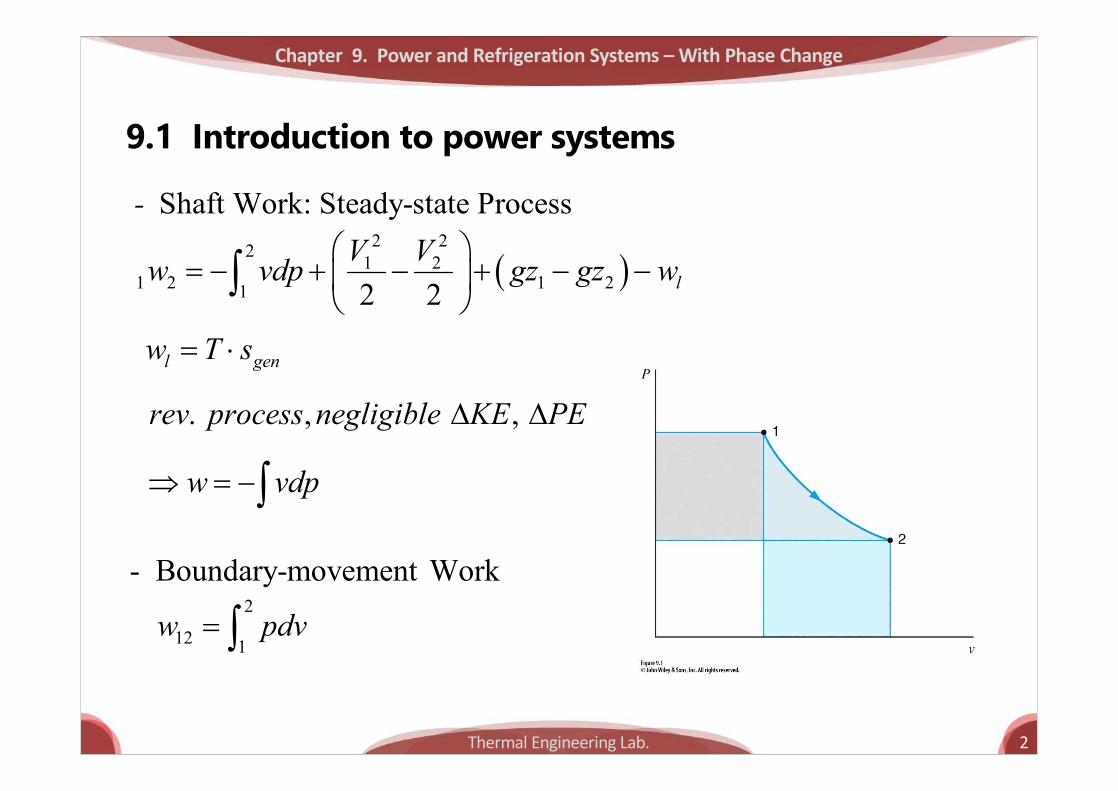
Shaft Work: Steady-state Process-
( )2 22 1 2
1 2 1 21 2 2 lV Vw vdp gz gz wæ ö
= - + - + - -ç ÷è ø
ò
l genw T s= ×
. , ,rev process negligible KE PED D
w vdpÞ = -ò
- Boundary-movement Work2
12 1w pdv= ò

Thermal Engineering Lab. 3
Chapter 9. Power and Refrigeration Systems – With Phase Change
-cycle 에대해서는
2 21 2
12 12 1 1 2 202 2
V Vq w h gz h gzæ ö æ ö
= - + + + - + +ç ÷ ç ÷è ø è ø
Tds dh vdp= -
( )2 2
2 1 121 1 lTds h h vdp q w= - - = +ò ò2 2
121 1gen genqds s Tds q T s
Td d d= + Þ = +ò ò
lw
òò =- pdvvdp
Thermal Engineering Lab. 4
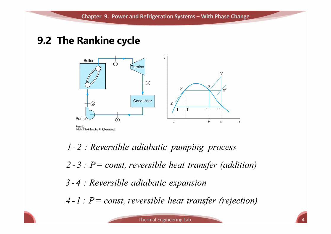
9.2 The Rankine cycle
Chapter 9. Power and Refrigeration Systems – With Phase Change
1- 2 : Reversible adiabatic pumping process
2 - 3 : P = const, reversible heat transfer (addition)
3 - 4 : Reversible adiabatic expansion
4 -1 : P = const, reversible heat transfer (rejection)

Thermal Engineering Lab. 5
Chapter 9. Power and Refrigeration Systems – With Phase Change
,
,
1 1 1 L avgL Lth
H H avgH
Tds T Sqq T STds
hD
= - = - = -D
òò
,
,
1 L avg
H avg
TT
= -
area 1-2-2'-3-4-1area a-2-2'-3-b-a
net H Lth
H H
w q qq q
h -= = =

Thermal Engineering Lab. 6
Chapter 9. Power and Refrigeration Systems – With Phase Change
average temperature*
2 1avg
Tds QTS S S
= =- Dò
avgT h ® 고온측에서는
avgT h¯ ® 저온측에서는
avgT
Thermal Engineering Lab. 7
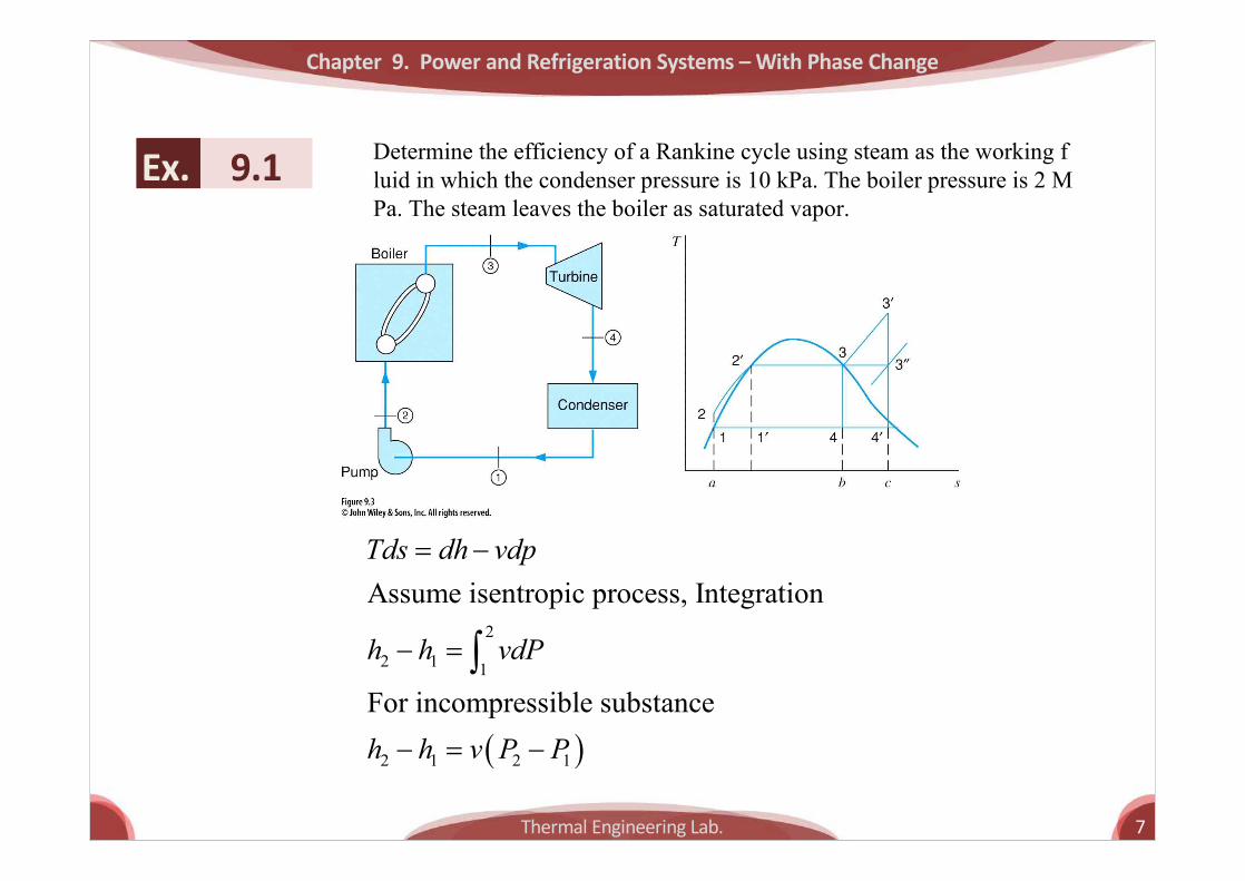
Ex. 9.1 Determine the efficiency of a Rankine cycle using steam as the working fluid in which the condenser pressure is 10 kPa. The boiler pressure is 2 MPa. The steam leaves the boiler as saturated vapor.
Chapter 9. Power and Refrigeration Systems – With Phase Change
( )
2
2 1 1
2 1 2 1
Assume isentropic process, Integration
For incompressible substance
Tds dh vdp
h h vdP
h h v P P
= -
- =
- = -
ò
Thermal Engineering Lab. 8
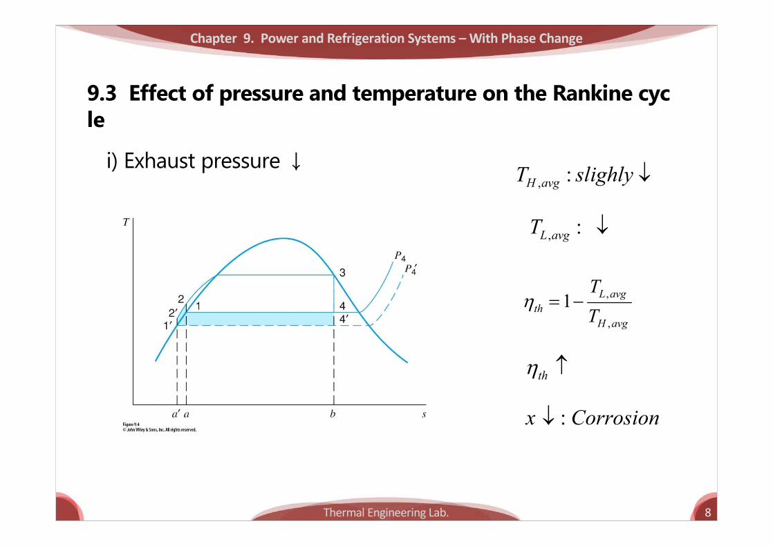
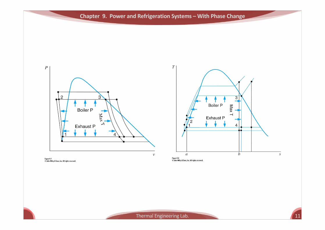
9.3 Effect of pressure and temperature on the Rankine cycle
Chapter 9. Power and Refrigeration Systems – With Phase Change
i) Exhaust pressure ↓
thh
:x Corrosion¯
, :H avgT slighly ¯
, : L avgT ¯
,
,
1 L avgth
H avg
TT
h = -
Thermal Engineering Lab. 9
Chapter 9. Power and Refrigeration Systems – With Phase Change
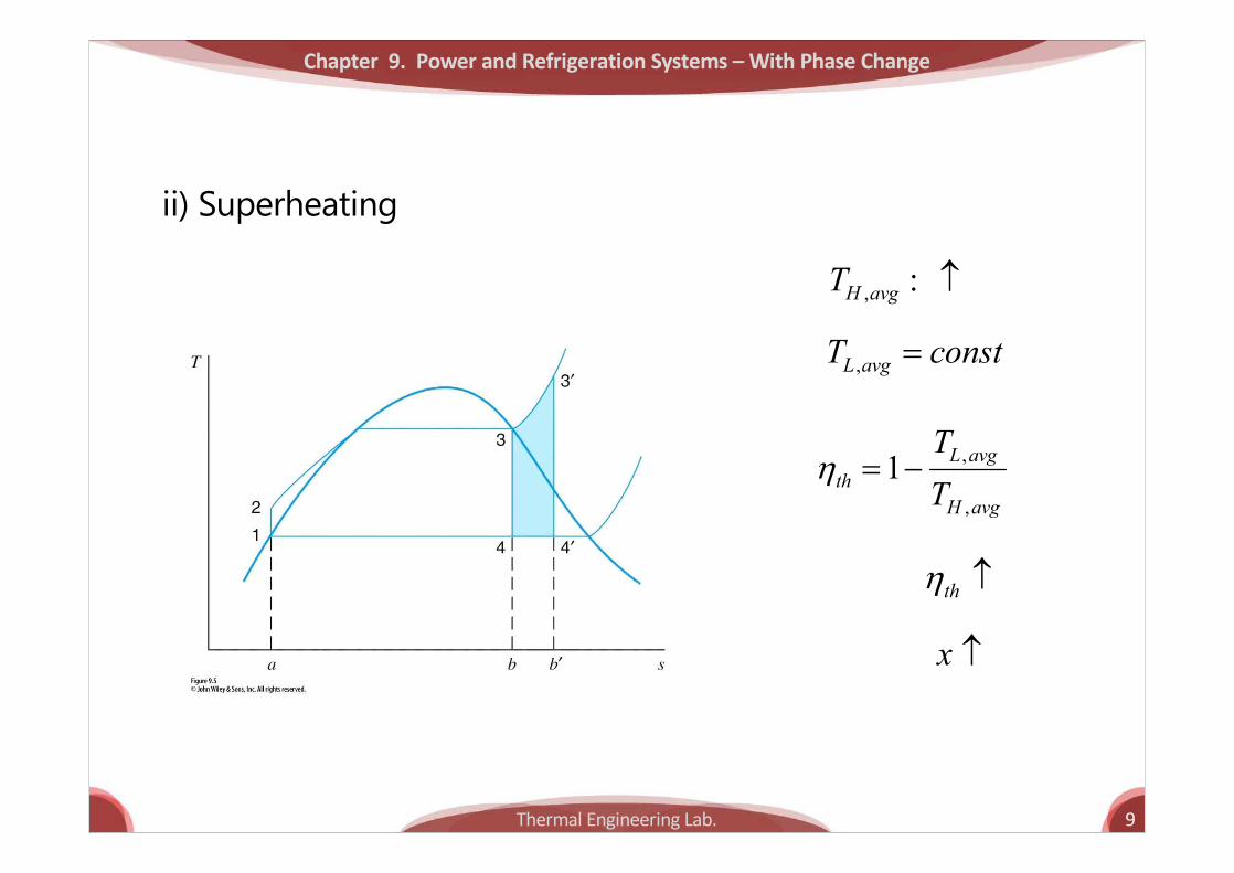
ii) Superheating
thh
x
, : H avgT
,L avgT const=
,
,
1 L avgth
H avg
TT
h = -
Thermal Engineering Lab. 10
Chapter 9. Power and Refrigeration Systems – With Phase Change
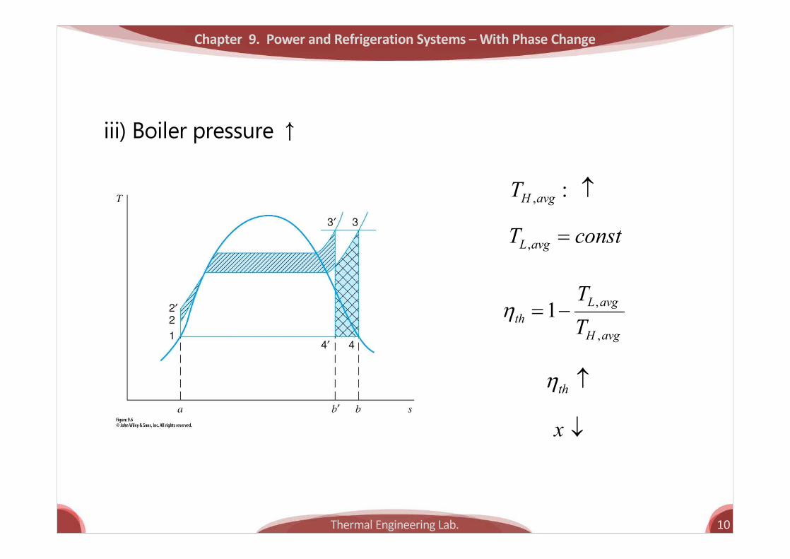
iii) Boiler pressure ↑
thh
x ¯
, : H avgT
,L avgT const=
,
,
1 L avgth
H avg
TT
h = -
Thermal Engineering Lab. 11
Chapter 9. Power and Refrigeration Systems – With Phase Change

Thermal Engineering Lab. 12
Ex. 9.2 In a Rankine cycle, steam leaves the boiler and enters the turbine at 4 MPa and 400℃. The condenser pressure is 10 kPa. Determine the cycle efficiency.
Chapter 9. Power and Refrigeration Systems – With Phase Change

Thermal Engineering Lab. 13
9.4 The Reheat cycle
Chapter 9. Power and Refrigeration Systems – With Phase Change
: thh 큰 변화 없음 :x
Thermal Engineering Lab. 14
Ex. 9.3 Consider a reheat cycle utilizing steam. Steam leaves the boiler and enters the turbine at 4 MPa, 400℃. After expansion in the turbine to 400 kPa, the steam is reheated to 400℃ and then expanded in the low-pressure turbine to 10 kPa. Determine the cycle efficiency.
Chapter 9. Power and Refrigeration Systems – With Phase Change

Thermal Engineering Lab. 15
9.5 The Regenerative cycle and feedwater heaters
Chapter 9. Power and Refrigeration Systems – With Phase Change
2-2' Rankine cycle
.
의평균 온도가 2'-3보다
낮기때문에 의효율은
Carnot cycle 보다 낮음

Thermal Engineering Lab. 16
Chapter 9. Power and Refrigeration Systems – With Phase Change
:not practicalheat transfer impossible
Ideal Regenerative cycle Carnot cycle Þ 과 동일한 열효율
• Ideal regenerative cycle – Carnot cycle과동일한열효율

Thermal Engineering Lab. 17
Chapter 9. Power and Refrigeration Systems – With Phase Change
• Regenerative cycle with open feedwater heater
Thermal Engineering Lab. 18
Ex. 9.4 Consider a regenerative cycle using steam as the working fluid. Steam leaves the boiler and enters the turbine at 4 MPa, 400℃. After expansion to 400 kPa, some of the steam is extracted from the turbine to heat the feedwater in an open FWH. The pressure in the FWH is 400 kPa, and the water leaving it is saturated liquid at 400 kPa. The steam not extracted expands to 10 kPa. Determine the cycle efficiency.
Chapter 9. Power and Refrigeration Systems – With Phase Change

Thermal Engineering Lab. 19
Chapter 9. Power and Refrigeration Systems – With Phase Change
• Regenerative cycle with closed feedwater heater
Thermal Engineering Lab. 20
Chapter 9. Power and Refrigeration Systems – With Phase Change
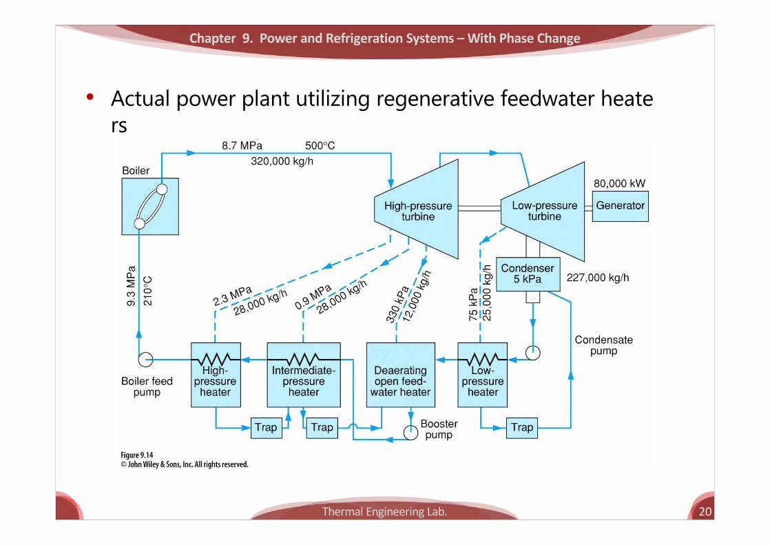
• Actual power plant utilizing regenerative feedwater heaters

Thermal Engineering Lab. 21
9.6 Deviation of actual cycles from ideal cycles
Chapter 9. Power and Refrigeration Systems – With Phase Change
Turbine Losses
Pump Losses
21 :actual21 :ideal
®® s
43 :actual43 :ideal
®® s

Thermal Engineering Lab. 22
Chapter 9. Power and Refrigeration Systems – With Phase Change
Piping Losses
a b : Pressure Loss®
b c : Heat Transfer®

Thermal Engineering Lab. 23
Ex. 9.5 A steam power plant operates on a cycle with pressures and temperatures as designated in Fig. 9.17. The efficiency of the turbine is 86%, and the efficiency of the pump is 80%. Determine the thermal efficiency of this cycle.
Chapter 9. Power and Refrigeration Systems – With Phase Change
Thermal Engineering Lab. 24
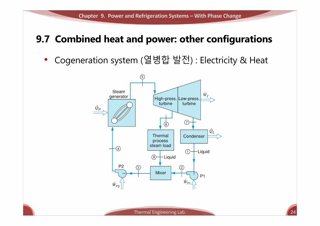
9.7 Combined heat and power: other configurations
Chapter 9. Power and Refrigeration Systems – With Phase Change
• Cogeneration system (열병합발전) : Electricity & Heat
Thermal Engineering Lab. 25
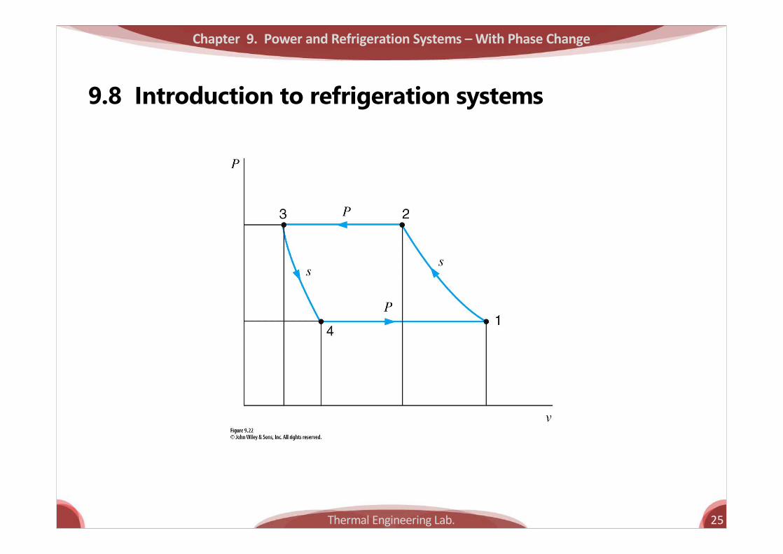
9.8 Introduction to refrigeration systems
Chapter 9. Power and Refrigeration Systems – With Phase Change

Thermal Engineering Lab. 26
9.9 The vapor-compression refrigeration cycle
Chapter 9. Power and Refrigeration Systems – With Phase Change
: refrigerator
: heat pump
L
c
H
c
qCOPw
qw
b
b
= =
¢ =
4 - 1 : P = const, evaporation3 - 4 : isenthalpic expansion2 - 3 : P = const, condensation1 - 2 : isentropic compression
COP: Coefficient of Performance
T
S
h
ln P
3
4
2
1
23
4 1S const=
2 1s s=4 3h h=
H L cq q w= +

Thermal Engineering Lab. 27
Chapter 9. Power and Refrigeration Systems – With Phase Change
1 : wet compression¢ 문제점
4 : isentropic expansion ¢ 문제점
구성의어려움
Thermal Engineering Lab. 28
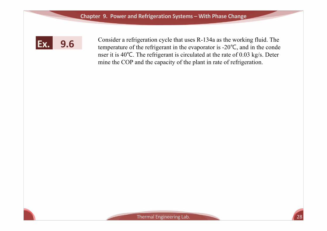
Ex. 9.6 Consider a refrigeration cycle that uses R-134a as the working fluid. The temperature of the refrigerant in the evaporator is -20℃, and in the condenser it is 40℃. The refrigerant is circulated at the rate of 0.03 kg/s. Determine the COP and the capacity of the plant in rate of refrigeration.
Chapter 9. Power and Refrigeration Systems – With Phase Change

Thermal Engineering Lab. 29
9.10 Working fluids for vapor-compression refrigeration systems
Chapter 9. Power and Refrigeration Systems – With Phase Change
3R -12, R - 22, R -11, NH134 , 22 407 , 410R -12 R a R R c R a® - ®
2
3
2
Natural Working Fluid:CONHH OPropane+Butane

Thermal Engineering Lab. 30
9.11 Deviation of the actual vapor-compression refrigeration cycle from the ideal cycle
Chapter 9. Power and Refrigeration Systems – With Phase Change
h
ln P
24
7 8
5
6 1
3
Thermal Engineering Lab. 31
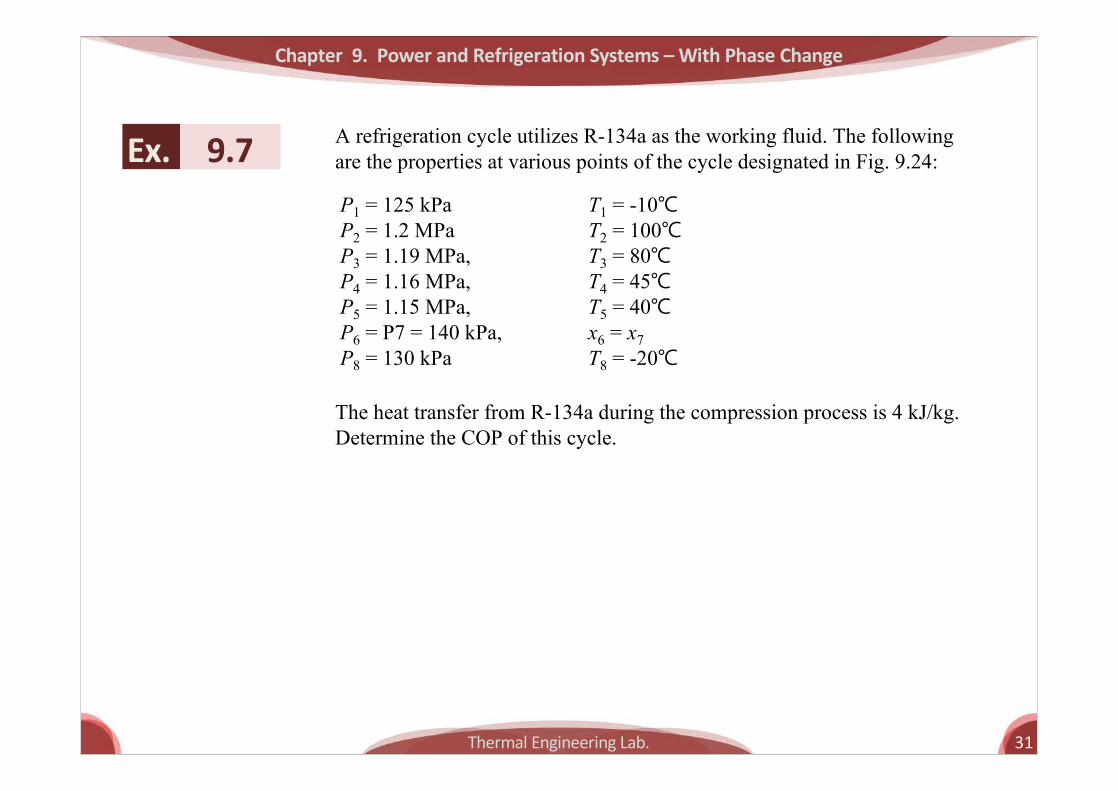
Ex. 9.7 A refrigeration cycle utilizes R-134a as the working fluid. The following are the properties at various points of the cycle designated in Fig. 9.24:
Chapter 9. Power and Refrigeration Systems – With Phase Change
P1 = 125 kPaP2 = 1.2 MPaP3 = 1.19 MPa,P4 = 1.16 MPa,P5 = 1.15 MPa,P6 = P7 = 140 kPa,P8 = 130 kPa
T1 = -10℃T2 = 100℃T3 = 80℃T4 = 45℃T5 = 40℃x6 = x7T8 = -20℃
The heat transfer from R-134a during the compression process is 4 kJ/kg. Determine the COP of this cycle.

Thermal Engineering Lab. 32
Chapter 9. Power and Refrigeration Systems – With Phase Change
9.12 Refrigeration cycle configurations

Thermal Engineering Lab. 33
Chapter 9. Power and Refrigeration Systems – With Phase Change
3 2 Cascade System(Netsle)NH CO-
Thermal Engineering Lab. 34
Chapter 9. Power and Refrigeration Systems – With Phase Change
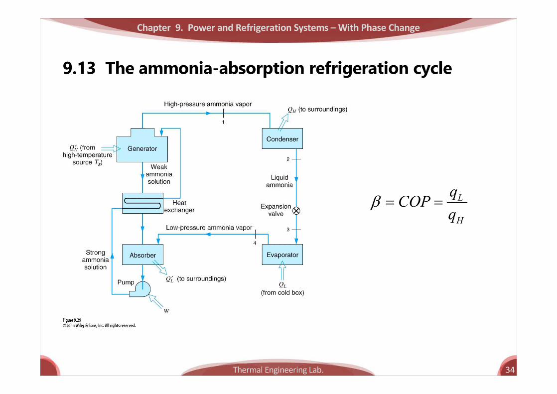
9.13 The ammonia-absorption refrigeration cycle
L
H
qCOPq
b = =


![IEEE MICROWAVE AND WIRELESS COMPONENTS …home.sogang.ac.kr/sites/rfdesign/lect/microwave/Lists/b6...literature such as multi-aperture, rat-race, branch guide, magic tee [3] ... input](https://static.fdocuments.in/doc/165x107/5b36ecce7f8b9a600a8b9723/ieee-microwave-and-wireless-components-home-such-as-multi-aperture-rat-race-branch.jpg)