Chapter 8 Pedestrian, Bicycle and Public Transit Facilities€¦ · · 2016-11-01Pedestrian,...
64
Topic #625-000-007 Plans Preparation Manual, Volume 1 January 1, 2017 Pedestrian, Bicycle and Public Transit Facilities 8-i Chapter 8 Pedestrian, Bicycle and Public Transit Facilities 8.1 General ........................................................................................... 8-1 8.1.1 Pedestrians and Bicyclists .............................................. 8-1 8.1.2 Transit ............................................................................... 8-4 8.2 References......................................................................................... 8-4 8.3 Pedestrian Facilities .......................................................................... 8-5 8.3.1 Sidewalks .......................................................................... 8-5 8.3.2 Curb Ramps.................................................................... 8-7 8.3.3 Detectable Warnings ....................................................... 8-8 8.3.4 Crosswalks ....................................................................... 8-8 8.3.4.1 Crosswalks at Intersections .......................... 8-9 8.3.4.2 Midblock Crosswalks ................................... 8-10 8.3.5 Railroad Crossing .......................................................... 8-11 8.4 Bicycle Facilities .............................................................................. 8-12 8.4.1 Bicycle Lanes ................................................................. 8-13 8.4.2 Bicycle Lane Between Through Lane and Right Turn Lane, Bus Bay or Parking Lane (Keyhole) .................. 8-14 8.4.2.1 Keyhole Locations ........................................ 8-14 8.4.2.2 Green Color Bicycle Lanes ......................... 8-14 8.4.3 Paved Shoulders ........................................................... 8-22 8.4.4 Wide Curb Lanes ........................................................... 8-22 8.4.5 Shared Lane Markings (Sharrows) .............................. 8-22 8.4.6 Bicycle Route Systems ................................................. 8-23 8.4.6.1 United States Bicycle Routes ..................... 8-24 8.5 Drainage and Utility Considerations .............................................. 8-26 8.6 Shared Use Paths ........................................................................... 8-26 8.6.1 Considerations ............................................................... 8-26
Transcript of Chapter 8 Pedestrian, Bicycle and Public Transit Facilities€¦ · · 2016-11-01Pedestrian,...

Topic #625-000-007 Plans Preparation Manual, Volume 1 January 1, 2017
Pedestrian, Bicycle and Public Transit Facilities 8-i
Chapter 8
Pedestrian, Bicycle and Public Transit Facilities
8.1 General ........................................................................................... 8-18.1.1 Pedestrians and Bicyclists .............................................. 8-18.1.2 Transit ............................................................................... 8-4
8.2 References ......................................................................................... 8-48.3 Pedestrian Facilities .......................................................................... 8-5
8.3.1 Sidewalks.......................................................................... 8-58.3.2 Curb Ramps.................................................................... 8-78.3.3 Detectable Warnings ....................................................... 8-88.3.4 Crosswalks ....................................................................... 8-8
8.3.4.1 Crosswalks at Intersections .......................... 8-98.3.4.2 Midblock Crosswalks ................................... 8-10
8.3.5 Railroad Crossing .......................................................... 8-118.4 Bicycle Facilities .............................................................................. 8-12
8.4.1 Bicycle Lanes ................................................................. 8-138.4.2 Bicycle Lane Between Through Lane and Right Turn
Lane, Bus Bay or Parking Lane (Keyhole).................. 8-148.4.2.1 Keyhole Locations ........................................ 8-148.4.2.2 Green Color Bicycle Lanes ......................... 8-14
8.4.3 Paved Shoulders ........................................................... 8-228.4.4 Wide Curb Lanes ........................................................... 8-228.4.5 Shared Lane Markings (Sharrows) .............................. 8-228.4.6 Bicycle Route Systems ................................................. 8-23
8.4.6.1 United States Bicycle Routes ..................... 8-248.5 Drainage and Utility Considerations.............................................. 8-268.6 Shared Use Paths ........................................................................... 8-26
8.6.1 Considerations ............................................................... 8-26

Topic #625-000-007 Plans Preparation Manual, Volume 1 January 1, 2017
Pedestrian, Bicycle and Public Transit Facilities 8-ii
8.6.2 Widths ............................................................................. 8-27
8.6.3 Cross Slopes .................................................................. 8-27
8.6.4 Grades ............................................................................ 8-27
8.6.5 Lateral Offset .................................................................. 8-28
8.6.6 Vertical Clearance .......................................................... 8-28
8.6.6 Vertical Clearance .......................................................... 8-29
8.6.7 Design Speed ................................................................. 8-29
8.6.8 Horizontal Alignment ..................................................... 8-29
8.6.8.1 Minimum Radii .............................................. 8-29
8.6.8.2 Stopping Sight Distance .............................. 8-30
8.6.9 Vertical Alignment .......................................................... 8-31
8.6.10 Separation between Shared Use Path and Roadway ... 8-31
8.6.11 Path Railings .................................................................. 8-32
8.6.12 Lighting ........................................................................... 8-32
8.6.13 Signing, Pavement Marking, and Signalization .......... 8-32
8.7 Bridges, Overpasses, and Underpasses ...................................... 8-33
8.7.1 Design Criteria ............................................................... 8-33
8.7.2 Prefabricated Steel Truss Bridges on FDOT Projects 8-36
8.7.2.1 Qualification of Prefabricated Steel Truss Pedestrian Bridge Producers....................... 8-37
8.7.2.2 Design and Detailing Responsibilities........ 8-37
8.7.2.3 Plans Development ...................................... 8-38
8.8 Drop-off Hazards for Pedestrians and Bicyclists ......................... 8-43
8.9 Strategic Intermodal System Highway Component Standards and Criteria 8-46
8.10 Public Transit Facilities ................................................................... 8-46
8.10.1 Boarding and Alighting Areas ....................................... 8-47
8.10.2 Street-Side Facilities ..................................................... 8-50
8.10.3 Exclusive Transit Running Ways ....................................... 8-51

Topic #625-000-007 Plans Preparation Manual, Volume 1 January 1, 2017
Pedestrian, Bicycle and Public Transit Facilities 8-iii
Tables Table 8.1.1 Bicycle Facilities............................................................... 8-2
Table 8.4.1 U. S. Bicycle Route Criteria .......................................... 8-25
Table 8.6.1 Maximum Grade Lengths ............................................. 8-28
Table 8.6.2 Minimum Radii for Horizontal Curves on Shared Use Paths.......................................................... 8-30
Table 8.6.3 Minimum Stopping Sight Distances ............................. 8-31
Figures Figure 8.3.1 Pedestrian Crossing Options........................................ 8-12
Figure 8.4.1 Bike Lane with Separate Right Turn Lane .................. 8-17
Figure 8.4.2 Bike Lane with Right Turn Drop Lane ......................... 8-18
Figure 8.4.3 Bike Lane with Channelized Right Turn Lane ............ 8-19
Figure 8.4.4 Bike Lane with Free Flow Channelized Right Turn Lane ....................................................................... 8-20
Figure 8.4.5 Bike Lane with Bus Bay ................................................ 8-21
Figure 8.6.1 Sign Placement on Shared Use Paths ........................ 8-32
Figure 8.7.1 Pedestrian/Shared Use Path Bridge Typical Section ............................................................................ 8-35
Figure 8.7.2 Prefabricated Pedestrian Bridge Standard Truss Configurations ..................................................... 8-41
Figure 8.7.3 Prefabricated Pedestrian Bridge Standard Truss Member Shapes .................................................. 8-41
Figure 8.7.4 Prefabricated Pedestrian Standard Bridge Cross-Sections ............................................................... 8-42
Figure 8.8.1 Drop-Off Hazards for Pedestrians and Bicyclists ....... 8-45
Figure 8.10.1 Accessible Boarding and Alighting Area for Flush Shoulder Roadways with Connection to Roadway ......................................................................... 8-48
Topic #625-000-007 Plans Preparation Manual, Volume 1 January 1, 2017
Pedestrian, Bicycle and Public Transit Facilities 8-iv
Figure 8.10.2 Accessible Boarding and Alighting Area for Flush Shoulder Roadways with Connection to Sidewalk ..................................................................... 8-49
Figure 8.10.3 Bus Stop and Bus Bay Categories .............................. 8-52
Exhibits Exhibit 8-A Sample Steel Truss Pedestrian Bridge Plans ............8-53
Topic #625-000-007 Plans Preparation Manual, Volume 1 January 1, 2017
Pedestrian, Bicycle and Public Transit Facilities 8-1
Chapter 8
Pedestrian, Bicycle and Public Transit Facilities
8.1 General
8.1.1 Pedestrians and Bicyclists
Section 335.065, Florida Statutes, Bicycle and pedestrian ways along state roads and transportation facilities establishes the following requirements:
“(1)(a) Bicycle and pedestrian ways shall be given full consideration in the planning and development of transportation facilities, including the incorporation of such ways into state, regional, and local transportation plans and programs. Bicycle and pedestrian ways shall be established in conjunction with the construction, reconstruction, or other change of any state transportation facility, and special emphasis shall be given to projects in or within 1 mile of an urban area.
(b) Notwithstanding the provisions of paragraph (a), bicycle and pedestrian ways are not required to be established: 1. Where their establishment would be contrary to public safety; 2. When the cost would be excessively disproportionate to the need or
probable use; 3. Where other available means or factors indicate an absence of need.”
In addition to this manual and the Department’s Design Standards, the United States Department of Justice 2010 Americans with Disabilities Act (ADA) Standards for Accessible Design and the United States Department of Transportation 2006 ADA Standards for Transportation Facilities guide the design of pedestrian facilities in the public right of way. Where the 2010 ADA Standards for Accessible Design or 2006 ADA Standards for Transportation Facilities do not address a specific issue, the draft Proposed Guidelines for Pedestrian Facilities in the Public Right-of-Way (PROWAG) provides best practices.
The Florida Accessibility Code contains scoping and technical requirements for accessibility to sites, facilities, buildings and elements by individuals with disabilities.

Topic #625-000-007 Plans Preparation Manual, Volume 1 January 1, 2017
Pedestrian, Bicycle and Public Transit Facilities 8-2
If the design criteria contained within the PPM for pedestrian and bicycle facilities are not met, a Design Variation is required. Reference which of the three conditions under Section 335.065 (1)(b), Florida Statutes support not providing a bicycle or pedestrian facility in the documentation.
Sidewalks and shared use paths are appropriate pedestrian facilities for all types of projects and locations. Beyond one mile of an urban area where only occasional pedestrian traffic is expected, a shoulder (paved and unpaved) would meet the need for a pedestrian way. Table 8.1.1 identifies appropriate bicycle facilities for various types of projects. The Urban Area 1-Mile Buffer Maps are posted in conjunction with the PPM.
Table 8.1.1 Bicycle Facilities
Location
Condition
Type of Work
New Construction,
Reconstruction
Resurfacing, Restoration,
Rehabilitation (RRR) 1, 2, 3
Traffic Operations, Intersection
Improvements
In or within one mile of an urban area
All Buffered Bicycle Lane
Buffered Bicycle Lane, Bicycle Lane, Wide Curb Lane, or Shared Lane with Shared Lane Markings (acceptable for posted speed 35 mph or less)
Buffered Bicycle Lane, Bicycle Lane, Wide Curb Lane, or Shared Lane with Shared Lane Markings (acceptable for posted speed 35 mph or less)
Beyond one mile of an urban area
Curb and Gutter
Buffered Bicycle Lane
Buffered Bicycle Lane, Bicycle Lane, Wide Curb Lane, or Shared Lane with Shared Lane Markings (acceptable for posted speed 35 mph or less)
Buffered Bicycle Lane, Bicycle Lane, Wide Curb Lane, or Shared Lane with Shared Lane Markings (acceptable for posted speed 35 mph or less)
Flush Shoulder Paved Shoulder Paved Shoulder Paved Shoulder
Topic #625-000-007 Plans Preparation Manual, Volume 1 January 1, 2017
Pedestrian, Bicycle and Public Transit Facilities 8-3
1. When no bicycle facilities exist, the widening of curbed sections for the project length to provide bicycle facilities may disproportionally affect the scope and cost of a RRR project, especially if reconstruction of the curb, sidewalk, and/or drainage system is required, additional right of way is needed, or utilities are impacted. No Design Variation is necessary, however, include a statement similar to the following in the project file:
“Bicycle facilities have been considered for this project but will not be provided, due to insufficient width between existing curb lines to provide bicycle facilities without substantial reconstruction of the roadway, drainage system and sidewalk (and/or requires additional right of way). Reconstruction (and/or right of way acquisition) is outside the scope of this project.”
2. Substantial widening of an existing curbed section is outside the scope of a RRR project and is considered reconstruction.
3. See Section 25.4.19 for options on RRR projects with existing roadways where no widening is planned.
Bicyclists and pedestrians should be expected on all of Florida’s state roadways except where restricted on limited access facilities and interstate highways (Section 316.091 Florida Statutes).
Coordinate with the District Pedestrian/Bicycle Coordinator during the project development and implementation process. Coordination with the District ADA Coordinator may also be necessary.
When considering “other available means” in accordance with F.S. 335.065 (1)(b)(3) (above), an alternate route or facility to serve cyclists and pedestrians should:
Meet the design criteria for bicycle and pedestrian facilities on state roadways.
Provide access to the same services, origination and destination sites, and transit connections as the project corridor.
Not result in a significant increase in travel time or trip length, exposure to motorized traffic or substantial elevation changes.
Provide appropriate locations to cross limited access, arterial or collector roadways, or rail corridors.

Topic #625-000-007 Plans Preparation Manual, Volume 1 January 1, 2017
Pedestrian, Bicycle and Public Transit Facilities 8-4
8.1.2 Transit
Provide connectivity between pedestrian or bicycle facilities and transit facilities.
Where transit service is provided or planned to be established, coordinate with the following:
District Pedestrian and Bicycle Coordinator
District Modal Development Office Coordinator
District ADA Coordinator
District Public Transportation staff
Local public transit provider(s)
Coordination will be required to determine the optimum location of boarding and alighting areas, transit shelters and bus bays.
Modification for Non-Conventional Projects:
Delete PPM 8.1.2 and see the RFP for requirements.
8.2 References
1. United States Department of Justice 2010 Americans with Disabilities Act (ADA) Standards for Accessible Design
2. United States Department of Transportation 2006 Americans with Disabilities Act (ADA) Standards for Transportation Facilities
3. Proposed Guidelines for Pedestrian Facilities in the Public Right-of-Way (PROWAG)
4. Florida Accessibility Code 5. FDOT Design Standards 6. FDOT Structures Manual, Current Edition 7. FDOT Traffic Engineering Manual 8. FDOT Manual on Uniform Traffic Studies (MUTS) 9. 2013 Accessing Transit Design Handbook
Topic #625-000-007 Plans Preparation Manual, Volume 1 January 1, 2017
Pedestrian, Bicycle and Public Transit Facilities 8-5
10. Manual on Uniform Traffic Control Devices (MUTCD) 11. Shared Use Path Level of Service Calculator, A User’s Guide (FHWA) 12. NCHRP Report 672 Roundabouts: An Informational Guide, Second Edition 13. AASHTO Guide for the Development of Bicycle Facilities 14. AASHTO Guide for the Planning, Design, and Operation of Pedestrian Facilities 15. AASHTO Guide for Geometric Design of Transit Facilities on Highways and
Streets, 1st Edition 16. Highway Capacity Manual 2010 17. AASHTO LRFD Bridge Design Specifications, Current Edition 18. Transportation Research Board (TRB) Guidelines for the Location and
Design of Bus Stops adapted from TCRP Report 19. Washington D.C.: National Academy Press
19. NACTO Urban Streets Design Guide 20. ITE/CNU Recommended Practice: Designing Walkable Urban Thoroughfares
8.3 Pedestrian Facilities
Provide separate walking areas, such as sidewalks or shared use paths, on roadways and bridges in or within one mile of the urban area, except where prohibited by Florida Statutes. Design sidewalks and shared use paths to comply with accessibility requirements. Refer to Section 8.6 for further information on designing shared use paths.
8.3.1 Sidewalks
Sidewalks are walkways parallel to the roadway and designed for use by pedestrians. Sidewalks should be provided along both sides of roadways that are in or within one mile of an urban area. If sidewalks are constructed on the approaches to bridges, they should be continued across the structure. If continuous sidewalks are constructed on only one side of the street, pedestrians should be provided access to facilities and services located on the opposite side of the street.
Topic #625-000-007 Plans Preparation Manual, Volume 1 January 1, 2017
Pedestrian, Bicycle and Public Transit Facilities 8-6
Modification for Non-Conventional Projects:
Delete the second sentence of the above paragraph and see RFP for additional requirements.
The minimum width of a sidewalk is 5 feet when the sidewalk is separated from the back of curb by 2 feet or more. If the sidewalk is located adjacent to the curb, the minimum width of sidewalk is 6 feet. Wider sidewalks are appropriate in locations where higher levels of pedestrian activity are expected.
Grades on sidewalks must not exceed 5% when not adjacent to a travel way unless accessible ramps are provided. There should be enough sidewalk cross slope to allow for adequate drainage; however, to comply with ADA requirements, the maximum cross slope is 2%. A clear 1-foot wide graded area with a maximum 1:6 slope should be provided adjacent to the sidewalk. Edge drop-offs should be avoided. When drop-offs cannot be avoided, they should be shielded as discussed in Section 8.8.
Provide a 5-foot wide (minimum) sidewalk that connects a transit stop or facility with an existing sidewalk or shared use path.
Evaluate the appropriate termini for pedestrian facilities (i.e., connect to existing sidewalk, pedestrian crossing or access point). Contact the District Pedestrian/Bicycle Coordinator for input on making a determination regarding continuous passage.
For roadways with flush shoulders, place new sidewalks in the following order of desirability: (1) As near the right of way line as possible. (2) Outside of the clear zone. (3) Five feet beyond the limits of the full width shoulder. (4) At the limits of the full width shoulder.
Sidewalks are not to be constructed directly adjacent to the roadway or shoulder pavement. Nearing intersections, the sidewalk should be transitioned as necessary to provide a more functional crossing location that also meets driver expectation. Further guidance on the placement of stop or yield lines and crosswalks is provided in the MUTCD, Part 3 and the Design Standards, Indexes 17344 and 17346.

Topic #625-000-007 Plans Preparation Manual, Volume 1 January 1, 2017
Pedestrian, Bicycle and Public Transit Facilities 8-7
8.3.2 Curb Ramps
A continuous accessible pedestrian route, including curb ramps, landings and transition areas (e.g., depressed corners, raised street crossings, flush roadway connections) are required along pedestrian networks. Additional information and details for curb ramps and landings are provided in the Design Standards, Index 304.
Include sidewalk curb ramps at the following locations:
All intersections and turnouts with curbed returns. Include a landing at the top of each ramp.
On curbed roadways between intersections where a crosswalk has been established
Pull boxes, manholes (and other utility covers), and other types of existing surface features in the location of a proposed curb ramp or detectable warning should be relocated. When relocation is not feasible, adjust the feature to meet the ADA requirements for surfaces (including the provision of a nonslip top surface, and adjustment to be flush with and at the same slope as the adjacent surface).
Curb ramps should be in line with the crossing and must provide a maximum slope of 1:12 (8.3 percent). At intersections where more than one road is crossed, provide curb ramps at both ends of each crossing. Crossings are required to meet the same grade and cross slope requirements as sidewalks. Where criteria for maximum cross slope cannot be met, process a Design Variation and provide the minimum attainable cross slope. When following the profile grade of the roadway, curb ramp slopes should not exceed 15 feet in length.
Evaluate existing driveways and turnouts for compliance to ADA requirements. Nonconforming driveways are not required to be upgraded if it is not feasible within the scope of the project.
Provide transition slopes (flared sides) where a pedestrian circulation path crosses the curb ramp. The maximum slope of transition slopes is 1:10, measured parallel with and adjacent to the curb line.

Topic #625-000-007 Plans Preparation Manual, Volume 1 January 1, 2017
Pedestrian, Bicycle and Public Transit Facilities 8-8
8.3.3 Detectable Warnings
Install detectable warnings to cover the full width of the walking surface and 2 feet deep. They are required on sidewalks and shared use paths at the following locations:
curb ramps and transition areas at street crossings
cut-through pedestrian refuge islands or medians six feet wide or greater
pedestrian at-grade rail crossings
commercial driveways with a stop sign, yield sign, or traffic signal
boarding and alighting areas adjacent to the roadway at bus stops where there is an at-grade connection to the roadway
edges of rail boarding platforms not protected by screens or guards
Detectable warnings should not be placed where sidewalk intersects urban flared turnouts or sidewalks that run continuously through residential driveways. Do not place detectable warnings on transition slopes or over grade breaks. Further guidance on detectable warnings is provided in Design Standards, Index 304.
The detectable warning systems on the APL are designed to work with concrete surfaces. In areas where the pedestrian facility has an asphalt surface, such as a shared use path, specify an appropriate detectable warning system. In these cases, consider including a short section of concrete that will accommodate any system.
8.3.4 Crosswalks
Crosswalks occur at all intersections (whether marked or not) and on any portion of a roadway distinctly indicated for pedestrian crossing by lines or other markings on the surface. Crossings should be convenient and minimize the pedestrian’s exposure in the roadway. Crosswalks are defined in Florida Statutes 316.003(6).
There are a number of treatments that may be used to help pedestrians safely cross the roadway, whether crossing at an intersection or midblock. A marked crosswalk is one of these tools. Marking of crosswalks helps drivers better identify the intersection and guides pedestrians to the best crossing location.
Topic #625-000-007 Plans Preparation Manual, Volume 1 January 1, 2017
Pedestrian, Bicycle and Public Transit Facilities 8-9
The criteria provided in this section do not apply to school crossings.
Additional guidance on marked crosswalks can be found in the FDOT Traffic Engineering Manual Section 3.8, AASHTO Guide for the Planning, Design, and Operation of Pedestrian Facilities and FHWA’s Safety Effects of Marked vs. Unmarked Crosswalks at Uncontrolled Locations: Executive Summary and Recommended Guidelines.
8.3.4.1 Crosswalks at Intersections
Provide marked crosswalks at all side streets where a pedestrian facility meets the roadway. As roadway volumes, speeds and number of travel lanes increase, marked crosswalks are best used in conjunction with other treatments (including signals, signs, beacons, curb extensions, raised medians, refuge islands, and enhanced overhead lighting).
When separated right turn lanes are used, place crosswalks so that an approaching motorist has a clear view of the pedestrian, and the crossing distance is minimized.
Coordinate with the District Traffic Operations Office for new marked crosswalks at uncontrolled intersection locations (without signals, stop or yield signs). Supplement marked crosswalks on an uncontrolled leg of an intersection with other treatments (which may include beacons, signals, curb extensions, raised medians, raised traffic islands, or enhanced overhead lighting) when any of the following conditions exist: (1) Where posted speeds are greater than 40 mph. (2) On a roadway with 4 or more lanes without a raised median or raised traffic island
that has an ADT of 12,000 or greater. (3) On a roadway with 4 or more lanes with a raised median or raised traffic island
that has or is projected to have (within 5 years) an ADT of 15,000 or greater.
Use Special Emphasis crosswalk markings at signalized intersections on all approaches, mid-block crossings, and school crossings per Design Standards, Index 17346.
Use standard crosswalk markings for stop or yield-controlled intersections where pedestrian facilities are present as shown in Design Standards, Index 17346.
Roundabouts present a unique challenge for the design of pedestrian crossings. In a roundabout, the crosswalk markings should comply with the MUTCD, Part 3, NCHRP Report 672 Roundabouts: An Informational Guide, Second Edition and the FDOT Traffic Engineering Manual.
Topic #625-000-007 Plans Preparation Manual, Volume 1 January 1, 2017
Pedestrian, Bicycle and Public Transit Facilities 8-10
8.3.4.2 Midblock Crosswalks
Midblock crosswalks can be used to supplement the pedestrian crossing needs in an area between intersections. This can provide pedestrians with a more direct route to their destination. Midblock crosswalks should be illuminated, marked and signed in accordance with the MUTCD, Traffic Engineering Manual, (Section 3.8) and Design Standards, Index 17346.
In addition to the requirements in Section 8.3.4.1, the following conditions also apply:
(1) Midblock crosswalks should not be located where the spacing between adjacent intersections is less than 660 feet
(2) Midblock crosswalks should not be located where the distance from the crosswalk to the nearest intersection (or crossing location) is less than 300 feet
(3) Do not place midblock crosswalks in locations where the crossing distance exceeds 60 feet (unless a median or a crossing island is provided)
(4) Do not place midblock crosswalks in locations where the sight distance for both the pedestrian and motorist is not adequate (stopping sight distance per Table 2.7.1)
(5) Do not place midblock crosswalks in locations where the ADA cross slope and grade criteria along the crosswalk cannot be met.
An engineering study is required before a marked midblock crosswalk is installed at an uncontrolled location. This study is required to examine such factors as sight distance for pedestrians and vehicles (stopping sight distance), traffic volume, turning volumes near proposed crosswalk location, roadway width, presence of a median, lighting, landscaping, drainage, traffic speed, adjacent land use (pedestrian generators / destinations), pedestrian volume and existing crossing patterns. Midblock crosswalks should only be used in areas where the need truly exists, and the engineering study will help to determine if an uncontrolled midblock crosswalk is a viable option. Refer to the Department's Traffic Engineering Manual, (Section 3.8) and Manual on Uniform Traffic Studies (MUTS).
If site conditions are identified that would obstruct the placement of a justified midblock crosswalk, include additional features in the design to remedy these conditions.. Features like overhead signing can help alert motorists and be used to light the crossing. Curb extensions or bulb-outs can improve sight distance and decrease the crossing distance. Adjustment of the profile on the roadway crossing may be required to improve the cross slope of the crosswalk.

Topic #625-000-007 Plans Preparation Manual, Volume 1 January 1, 2017
Pedestrian, Bicycle and Public Transit Facilities 8-11
8.3.5 Railroad Crossing
Provide an ADA accessible route for pedestrians at railroad crossings by extending proposed or existing sidewalks or shared use paths through the rail crossing. The surface of the crossing must be:
Firm, stable and slip resistant,
Level and flush with the top of rail at the outer edges of the rails, and
Area between the rails aligns with the top of rail.
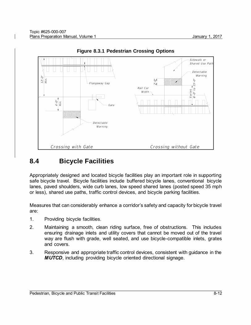
Place detectable warnings on each side of the railroad crossing as illustrated in Figure 8.3.1.
The edge of the detectable warning nearest the rail crossing is to be located between 6 and 15 feet from the centerline of the nearest rail. Where gates are provided, detectable warnings are to be placed a minimum of 4 feet from the side of the gates opposite the rail.
An audible device, such as a bell, is used in conjunction with the traffic control signals, if traffic control signals are in operation at a crossing that is used by pedestrians or bicyclists. Additional information is located in the MUTCD regarding additional signals, signs, or pedestrian gates and designing crossings for shared use paths.
Flangeway gaps are necessary to allow the passage of train wheel flanges; however, they pose a potential hazard to pedestrians who use wheelchairs because the gaps can entrap the wheelchair casters. A maximum flangeway gap is required for all at-grade pedestrian rail crossings of 2½” for all non-freight rail track and 3” for freight rail track.
Topic #625-000-007 Plans Preparation Manual, Volume 1 January 1, 2017
Pedestrian, Bicycle and Public Transit Facilities 8-12
Figure 8.3.1 Pedestrian Crossing Options
8.4 Bicycle Facilities
Appropriately designed and located bicycle facilities play an important role in supporting safe bicycle travel. Bicycle facilities include buffered bicycle lanes, conventional bicycle lanes, paved shoulders, wide curb lanes, low speed shared lanes (posted speed 35 mph or less), shared use paths, traffic control devices, and bicycle parking facilities.
Measures that can considerably enhance a corridor’s safety and capacity for bicycle travel are: 1. Providing bicycle facilities. 2. Maintaining a smooth, clean riding surface, free of obstructions. This includes
ensuring drainage inlets and utility covers that cannot be moved out of the travel way are flush with grade, well seated, and use bicycle-compatible inlets, grates and covers.
3. Responsive and appropriate traffic control devices, consistent with guidance in the MUTCD, including providing bicycle oriented directional signage.

Topic #625-000-007 Plans Preparation Manual, Volume 1 January 1, 2017
Pedestrian, Bicycle and Public Transit Facilities 8-13
8.4.1 Bicycle Lanes
Where required by Table 8.1.1, provide a bicycle lane for each direction of travel on the roadway. The bicycle lane is defined as the area between the edge of travel lane and the edge of pavement. Bicycle lanes are to be marked in accordance with Design Standards, Index 17347 and the MUTCD. Shared use paths do not meet the requirement for bicycle lanes.
For new construction or reconstruction projects, both curbed and flush shoulder roadways, the standard width of a buffered bicycle lane is 7 feet. For high-speed curbed arterials, the standard width of a buffered bicycle lane is 6.5 feet.
For RRR projects, the distribution of available roadway width may require a bicycle lane other than the standard buffered bicycle lane (refer to Section 25.4.19.2 of this Volume). When providing a bicycle lane on a RRR project, the options in the order of priority are:
1. 7-foot buffered bicycle lane 2. 6-foot buffered bicycle lane 3. 5-foot conventional bicycle lane 4. 4-foot conventional bicycle lane
The width of the buffer zone for the 6 foot and 7 foot buffered bicycle lane is depicted in Design Standards, Index 17347. A Buffered Bicycle Lane should not exceed 7 feet in width. For RRR projects, any additional pavement width that results from restricting the Buffered Bicycle Lane to 7 feet should be applied to the outside travel lane.
At an intersection approach, the buffer striping will transition to a double 6 inch wide stripe using a 2/4 skip pattern. The transition will begin 150 feet in advance of an intersection to provide sufficient distance for an automobile or truck to merge into the bicycle lane before turning right. The buffer striping will not be broken at low-volume or residential driveways.
When a guardrail or other barrier exists and the roadway pavement is continuous to the face of the barrier, the minimum bicycle lane width is 5 feet. Refer to Section 8.4.2 of this chapter when the bicycle lane is adjacent to a right-turn lane or bus bay.
Bicycle lanes are one-way facilities and carry bicycle traffic in the same direction as adjacent motor vehicle traffic. On one-way streets, bicycle lanes should generally be placed on the right side of the street. A bicycle lane on the left side of the street can be considered if it will substantially reduce the number of potential conflicts, such as those caused by frequent bus traffic, heavy right-turn movements, high-turnover parking lanes, or if there is a significant number of left-turning bicyclists.

Topic #625-000-007 Plans Preparation Manual, Volume 1 January 1, 2017
Pedestrian, Bicycle and Public Transit Facilities 8-14
8.4.2 Bicycle Lane Between Through Lane and Right Turn Lane, Bus Bay or Parking Lane (Keyhole)
8.4.2.1 Keyhole Locations
In new construction, reconstruction and traffic operations projects, at locations with right turn lanes, bus bays or parking lanes, provide a bicycle lane, known as a keyhole lane, between the through lane and the right turn lane, bus bay or parking lane. The width of the keyhole lane should be the same as the width of the approaching bicycle lane; i.e. a 7-foot keyhole lane for an approaching 7-foot buffered bicycle lane. However, the minimum width of the keyhole lane is 5 feet.
For bicycle lanes adjacent to parking lanes, a 7-foot wide buffered bicycle lane should be provided using a 3-foot buffer adjacent to the parking lane hatched with 10-foot diagonal spacing. Shared lane markings should be used if width is inadequate for the 7-foot buffered bicycle lane.
When a RRR project includes the addition or modification of a right turn lane or bus bay, provide a 5-foot minimum width bicycle lane between the through lane and the right turn lane or bus bay, if existing right of way is adequate.
When a RRR project has an existing right turn lane without a bicycle lane between the through lane and right turn lane, bus bay or parking lane, a bicycle lane should be provided. Factors to be considered include the opportunity to provide a continuous alignment, reduce the potential for conflicts with turning vehicles, and availability of right of way.
8.4.2.2 Green Color Bicycle Lanes
The Federal Highway Administration (FHWA) has issued an Interim Approval for the use of green colored pavement in marked bicycle lanes and in extensions of bicycle lanes through intersections and other traffic conflict areas. In accordance with the conditions of the interim approval, FDOT has requested and received permission from FHWA for locations on the State Highway System. The Interim Approval may be found at the following website:
http://mutcd.fhwa.dot.gov/res-interim_approvals.htm
Topic #625-000-007 Plans Preparation Manual, Volume 1 January 1, 2017
Pedestrian, Bicycle and Public Transit Facilities 8-15
Green colored bike lanes are optional and may be used to enhance the conspicuity of bicycle lane conflict areas. The following guidelines apply to their use on the State Highway System.
Green color bicycle lanes are permitted at any of the following traffic conflict areas when the speed limit of the roadway is greater than 35 mph:
a. The bike lane crosses a right turn lane b. Traffic in a channelized right turn lane crosses a bike lane c. The bike lane is adjacent to a dedicated bus bay d. A bike lane transitions across a free-flow merge lane or lane addition, such as
at an interchange
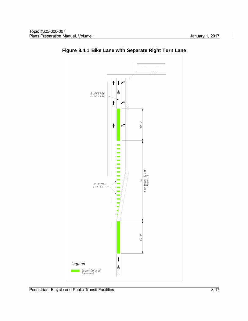
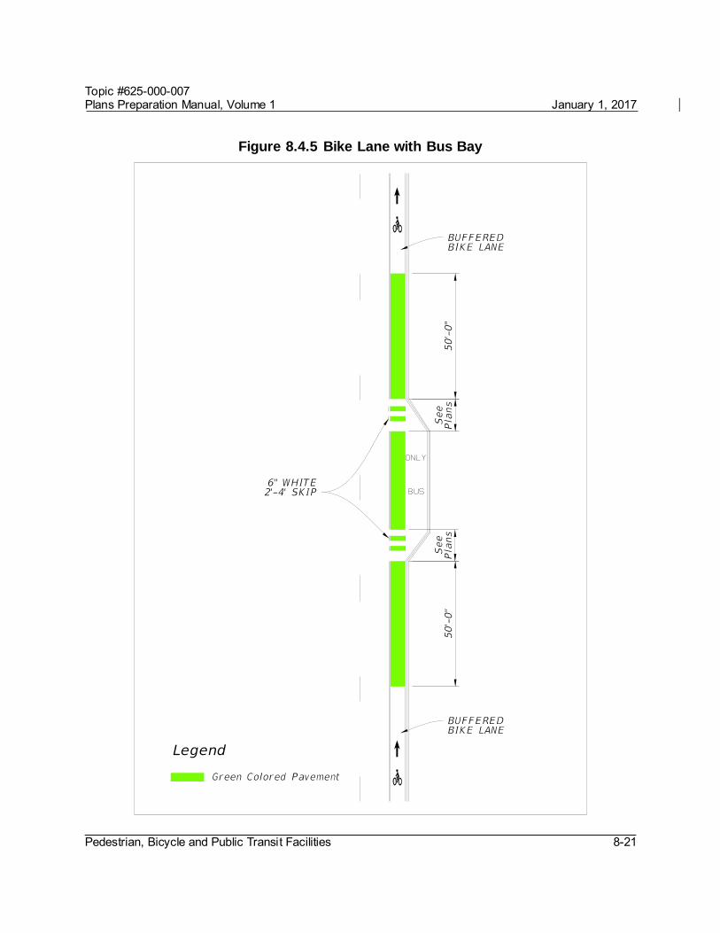
Green colored pavements cannot replace or be used in lieu of required markings for bike lanes as defined in this Chapter and the MUTCD, and will only supplement such markings. When used in conjunction with white skip lines, such as when extending a bike lane across a right turn lane or access to a bus bay, the transverse colored marking must match the 2’-4’ white skip line pattern of the bike lane extension. Start the green colored pavement as a solid pattern 50 feet in advance of the skip striping, match the 2’-4’ skip through the conflict area, and then resume the solid color for 50 feet after the conflict area, unless such an extent is interrupted by a stop bar, an intersection curb radius or bike lane marking. Include details of each installation and associated pavement markings in the plans. Figures 8.4.1 – 8.4.5 illustrate how the green portion of the bike lane may be marked. Refer to Design Standards, Indexes 17346 and 17347 for details on pavement markings.
Materials used to color the bike lane green must:
be non-reflective
meet FDOT Specification 523, Patterned Pavement, and
fall within the color parameters defined by FHWA in their interim approval.
During the first three years of the installation, the District will review annually the crash reports in the conflict area to assess if the green colored pavement is improving the safety of the bike lane. These assessments will be reported to the State Roadway Design Engineer.

Topic #625-000-007 Plans Preparation Manual, Volume 1 January 1, 2017
Pedestrian, Bicycle and Public Transit Facilities 8-16
Obtain approval for site specific installations of green colored bicycle lanes from the District Design Engineer, and provide a copy of the approval to the State Roadway Design Engineer. The addition of green colored pavement to bicycle lanes per these criteria does not require a local agency maintenance agreement. FDOT may fund the assessment of need, but will be responsible for the design, construction and maintenance of the green colored pavement if its need has been demonstrated in accordance with the requirements above.
Modification for Non-Conventional Projects:
Delete the last sentence in the above paragraph and see RFP for requirements.
Topic #625-000-007 Plans Preparation Manual, Volume 1 January 1, 2017
Pedestrian, Bicycle and Public Transit Facilities 8-17
Figure 8.4.1 Bike Lane with Separate Right Turn Lane

Topic #625-000-007 Plans Preparation Manual, Volume 1 January 1, 2017
Pedestrian, Bicycle and Public Transit Facilities 8-18
Figure 8.4.2 Bike Lane with Right Turn Drop Lane

Topic #625-000-007 Plans Preparation Manual, Volume 1 January 1, 2017
Pedestrian, Bicycle and Public Transit Facilities 8-19
Figure 8.4.3 Bike Lane with Channelized Right Turn Lane

Topic #625-000-007 Plans Preparation Manual, Volume 1 January 1, 2017
Pedestrian, Bicycle and Public Transit Facilities 8-20
Figure 8.4.4 Bike Lane with Free Flow Channelized Right Turn Lane
Topic #625-000-007 Plans Preparation Manual, Volume 1 January 1, 2017
Pedestrian, Bicycle and Public Transit Facilities 8-21
Figure 8.4.5 Bike Lane with Bus Bay

Topic #625-000-007 Plans Preparation Manual, Volume 1 January 1, 2017
Pedestrian, Bicycle and Public Transit Facilities 8-22
8.4.3 Paved Shoulders
A paved shoulder is a portion of a roadway which has been delineated by edge line striping, and may include bicycle lane pavement markings or signing. In or within 1 mile of an urban area, mark the paved shoulder as a bicycle lane in accordance with Section 8.4.1. When used, rumble striping is to be applied to the line dividing the bike lane from the travel lane. For additional information, see Section 2.3 and Section 7.6.1.2 of this Volume, and Design Standards, Index 519 or D519. Paved shoulders must be 5 feet in width for new construction and reconstruction projects. An existing paved shoulder of at least 4 feet in width is considered to be a bicycle facility; however a minimum 5-foot clear width between the traveled way and the face of curb, guardrail or other roadside barrier is required.
8.4.4 Wide Curb Lanes
Wide curb lanes are through lanes which provide a minimum of 14 feet in width, which allows most motor vehicles to pass cyclists safely within the travel lane. Wide curb lanes do not meet Department requirements for bicycle facilities on new construction or reconstruction projects. However, in some conditions, such as RRR projects, they may be the only practical option for a bicycle facility.
8.4.5 Shared Lane Markings (Sharrows)
The shared lane marking is an optional pavement marking for shared lane roadways. It may be used to assist bicyclists on a roadway open to bicycle travel where no bicycle lane or paved shoulder exists or is feasible. Shared lane markings should be limited to roadways with a posted speed of 35 mph or less. They are not intended to be placed on all roadways that do not have a marked bike lane, or on shared use paths. Shared lane markings provide guidance to cyclists in their lateral positioning, especially on roadways with on-street parking or lanes that are too narrow to share side by side with a motor vehicle. They also help to discourage wrong way riding and encourage safer passing of bicyclists by motorists. Shared lane markings may be used to identify an alternate route as part of an approved temporary traffic control plan.
Topic #625-000-007 Plans Preparation Manual, Volume 1 January 1, 2017
Pedestrian, Bicycle and Public Transit Facilities 8-23
Modification for Non-Conventional Projects:
Delete the third sentence of the above paragraph and replace with the following: Shared lane markings are limited to roadways with a posted speed of 35 mph or less.
Following are conditions where shared lane markings should be considered on the State Highway System:
In conjunction with on-street parking Where forward sight distance is limited due to horizontal or vertical curvature Where gaps exist between bicycle facilities or between an existing bicycle facility
and an urban center, school, park, or transit hub When the roadway has an average bicycle crash history of 3 or more per mile,
over a 3 year period
Install shared lane markings in accordance with Design Standards, Index 17347 and the MUTCD.
8.4.6 Bicycle Route Systems
Bicycle routes include roadways or shared use paths designated through signage, pavement markings or mapping. They provide directional and distance information, and aid bicyclists in wayfinding, especially in complex urban locations or along established long distance bicycle routes. Do not terminate bicycle routes at a barrier. Follow the guidance in the MUTCD, Part 9 when including information directing bicyclists around temporary interruptions in a route.
The decision whether to provide bicycle route systems should be based on the suitability of the particular roadway or shared use path for bicycle travel and the need for wayfinding information. Evaluations of suitability should include roadway width, volume, speed, and types of traffic, parking conditions, grade, sight distance, and connectivity to services, significant destinations, and local transit or regional transportation hubs. Other considerations include location and condition of drainage grates, railroad crossings, pavement surface, signals responsive to bicycles, and maintenance schedules. Further guidance on signing bicycle route systems is provided in the MUTCD, Part 9.

Topic #625-000-007 Plans Preparation Manual, Volume 1 January 1, 2017
Pedestrian, Bicycle and Public Transit Facilities 8-24
8.4.6.1 United States Bicycle Routes
The U.S. Bicycle Route System is a network of bicycle routes that span multiple states and are of national or regional significance. These routes are nominated for national designation by State Departments of Transportation (DOTs), and designated and catalogued by the American Association of State Highway and Transportation Officials (AASHTO).
Florida has adopted a policy entitled U.S. Numbered Bicycle Routes, Topic No. 000-525-060 in support of the national route system.
Table 8.4.1 identifies criteria to use when selecting a route within a USBR corridor. These criteria provide an objective process for evaluating route options, but should be followed by a subjective review of the highest scored candidates to establish the final route. Reflecting on the specific purpose of the corridor can help to narrow final route selection. Route options are scored on a scale from 3 = Fulfills selection criteria to 0 = Does not contribute to meeting selection criteria. NA may be used when the criteria does not apply.

Topic #625-000-007 Plans Preparation Manual, Volume 1 January 1, 2017
Pedestrian, Bicycle and Public Transit Facilities 8-25
Table 8.4.1 U. S. Bicycle Route Criteria Macro Criteria 3 2 1 0 NA
Within USBR corridor, with an emphasis on intrinsic scenic and cultural qualities of the corridor itself.
Provides access to scenic, cultural, historical and recreational destinations. (May not be directly on route but are nearby.)
Links major metropolitan areas to connect cyclists to transportation hubs or major attractions.
Provides reasonably direct route in connecting cities or attractions along the corridor.
Supports natural connections between adjoining states, Canada, or Mexico.
Includes or intersects major existing and planned bicycle routes (interstate, cross-state, or intrastate) that are suitable for travel by touring bicycles.
Micro Criteria 3 2 1 0 NA
Meets established state or local design criteria for on-road facilities and shared use paths. (Low volume or low speed roads without specific accommodation can be appropriate. High traffic roads may be necessary as short links.)
Utilizes already established and successful routes or paths
Easy to follow with limited turns; is well marked or has easily identified permanent landmarks to enable navigation.
Connects to at least one neighboring state’s USBR or another country’s suitable roadway, bicycle route, or trail system.
Provides access to services and amenities. Daily needs include food, water and overnight accommodations (including camping) at appropriate intervals (40-60 miles). Amenities and services not required daily include restaurants, libraries, and bicycle shops.
Ferry or shuttle crossings of water bodies or other barriers have regularly scheduled service available to cyclists. An alternate route should be identified for when ferries or shuttles are out of service (seasonal) or when scheduled service is infrequent.
Considers difficulty of the region's topography, avoiding extreme climbs. Topography considerations should be balanced against scenic values, points of interest, access to services, and route directness.
Total
Topic #625-000-007 Plans Preparation Manual, Volume 1 January 1, 2017
Pedestrian, Bicycle and Public Transit Facilities 8-26
8.5 Drainage and Utility Considerations
Drainage inlets, grates and utility covers are potential problems for bicyclists. When a new roadway is designed, grates and covers should be kept out of bicyclists’ expected path. For RRR projects refer to Section 25.4.19.2 of this volume. Refer to Section 3.7 Hydraulic Openings and Protective Treatment of the Department’s Drainage Manual and Design Standards for further information in selecting appropriate grates and inlet tops.
See Chapter 4 of this volume for lateral offsets for light poles.
8.6 Shared Use Paths
Shared use paths are paved facilities physically separated from motorized vehicular traffic by an open space or barrier and either within the highway right of way or an independent right of way. Shared use paths are used by bicyclists, pedestrians, skaters, runners and others. Since shared use paths serve as pedestrian facilities, they are required to be accessible. In addition to the requirements of this manual for accessible pedestrian facilities, the bicycle’s operating characteristics will govern the design of shared use paths. The term path as used in this section refers to these paved shared use paths. An example typical design is provided for guidance in Volume 2, Exhibit TYP-20.
8.6.1 Considerations
Shared use paths adjacent to a roadway may be considered if the following conditions are met: 1. The path will be separated from the roadway. 2. There will be few access points or roadways crossing the path. 3. There will be adequate access to local streets and other facilities along the path. 4. There is a commitment to provide path continuity with other bikeways throughout
the corridor.
Shared use paths are not replacements for on-street bicycle lanes. Within a roadway right of way, bicycle lanes are the safest, most efficient bicycle facility. When paths are located immediately adjacent to roadways, some operational problems are likely to occur:

Topic #625-000-007 Plans Preparation Manual, Volume 1 January 1, 2017
Pedestrian, Bicycle and Public Transit Facilities 8-27
1. Paths require one direction of bicycle traffic to ride against motor vehicle traffic, which is contrary to the normal Rules of the Road. Motorists are not in the habit of scanning for traffic from that direction.
2. At path ends, bicyclists riding against traffic will tend to continue to travel on the wrong side of the street, as do bicyclists getting on to a path. Wrong-way travel by bicyclists is a major cause of bicycle/automobile crashes and should be discouraged.
3. Many bicyclists will use the roadway instead of the path because they have found the roadway to be safer, less congested, more convenient, or better maintained.
8.6.2 Widths
The appropriate paved width for a shared use path is dependent upon context, volume and mix of users. Typically, widths range from 10 to 14 feet, with the wider values applicable to areas with high use and/or a wider variety of users (bicyclists, pedestrians, joggers, and skaters). The need to provide for larger emergency or maintenance vehicles or manage steep grades can also affect appropriate width. The minimum width for a two-directional shared use path is 10 feet. FHWA’s Shared Use Path Level of Service Calculator may be used as a guide in determining when a width greater than the minimum might be needed.
Design curb ramps to be the same width as the path. At locations where the path narrows from the typical width warning signs or pavement markings in conformance with the MUTCD should be used.
8.6.3 Cross Slopes
To meet ADA requirements, the maximum cross slope on shared use paths is 2%.
8.6.4 Grades
To meet ADA requirements, the maximum longitudinal grade is 5%. Grades greater than 5% should be considered ramps and designed accordingly. Maximum ramp slopes are 8.33% and can have a maximum rise of 30 inches, with a level landing at least 60 inches in length.
To accommodate bicyclists, grades should not exceed 5%, since steeper grades cause difficulties for many bicyclists. If the terrain makes it necessary to use steeper grades on short sections, the following restrictions are recommended:

Topic #625-000-007 Plans Preparation Manual, Volume 1 January 1, 2017
Pedestrian, Bicycle and Public Transit Facilities 8-28
Table 8.6.1 Maximum Grade Lengths
Grade (%) Maximum Length
6% For up to 800 feet
7% For up to 400 feet
8% For up to 300 feet
9% For up to 200 feet
10% For up to 100 feet
11+% For up to 50 feet
NOTE: When using a longer grade, 4 to 6 feet of additional width should be added to the path to allow some bicyclists to dismount and walk their bicycles. Clear distances and sight distances should be adjusted to accommodate longer grades.
Refer to Section 8.6.9 for controls on grade changes.
8.6.5 Lateral Offset
Provide a minimum 4-foot lateral offset to obstruction on both sides of a shared use path. Maintain a 2-foot wide graded area with a maximum 1:6 slope adjacent to both sides of the path.
Edge drop-offs should be avoided. When drop-offs cannot be avoided they should be shielded as discussed in Section 8.8.
See Figure 8.6.1 in Section 8.6.13 for lateral offset criteria for signs on shared use paths.
8.6.6 Vertical Clearance
Provide a minimum 8-foot vertical clearance to obstructions. A 10-foot vertical clearance is desirable when equestrians or maintenance and emergency vehicles are to be accommodated. A 10-foot vertical clearance is also desirable for underpasses and tunnels.
Topic #625-000-007 Plans Preparation Manual, Volume 1 January 1, 2017
Pedestrian, Bicycle and Public Transit Facilities 8-29
Modification for Non-Conventional Projects:
Delete Section 8.6.6 and replace with the following:
8.6.6 Vertical Clearance
Provide a minimum 8-foot vertical clearance to obstructions. See RFP for additional requirements.
8.6.7 Design Speed
For paths in relatively flat areas (grades less than or equal to 4%), use a design speed of 18 mph. When a downgrade exceeds 4 percent, a design speed of 30 mph should be used.
8.6.8 Horizontal Alignment
8.6.8.1 Minimum Radii
The minimum radius of curvature based upon superelevation for a shared use path is calculated based upon the following formula:
R = [V2/15*(e/100 ± f)] where: R = Minimum radius of curvature (feet) V = Design speed (mph) e = rate of bikeway super elevation (percent) f = coefficient of friction
The effective superelevation is usually limited to the existing 2% cross slope and may be positive or negative. If a transition is needed, then a minimum 75-foot transition should be used. See Table 8.6.2 for minimum radii for shared use paths. Further information on calculating the minimum radii may be found in the AASHTO Guide for the Development of Bicycle Facilities, 2012.
Topic #625-000-007 Plans Preparation Manual, Volume 1 January 1, 2017
Pedestrian, Bicycle and Public Transit Facilities 8-30
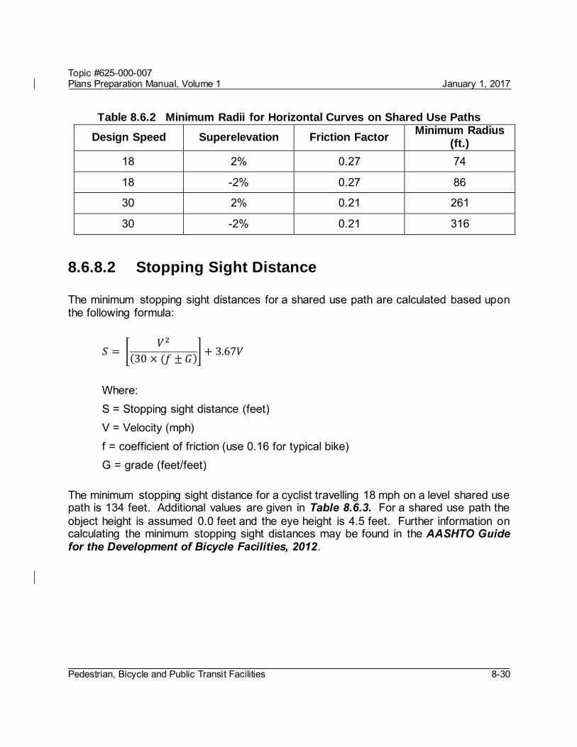
Table 8.6.2 Minimum Radii for Horizontal Curves on Shared Use Paths
Design Speed Superelevation Friction Factor Minimum Radius
(ft.)
18 2% 0.27 74
18 -2% 0.27 86
30 2% 0.21 261
30 -2% 0.21 316
8.6.8.2 Stopping Sight Distance
The minimum stopping sight distances for a shared use path are calculated based upon the following formula:
𝑆 = [𝑉2
(30 × (𝑓 ± 𝐺)] + 3.67𝑉
Where: S = Stopping sight distance (feet)
V = Velocity (mph) f = coefficient of friction (use 0.16 for typical bike) G = grade (feet/feet)
The minimum stopping sight distance for a cyclist travelling 18 mph on a level shared use path is 134 feet. Additional values are given in Table 8.6.3. For a shared use path the object height is assumed 0.0 feet and the eye height is 4.5 feet. Further information on calculating the minimum stopping sight distances may be found in the AASHTO Guide for the Development of Bicycle Facilities, 2012.
Topic #625-000-007 Plans Preparation Manual, Volume 1 January 1, 2017
Pedestrian, Bicycle and Public Transit Facilities 8-31
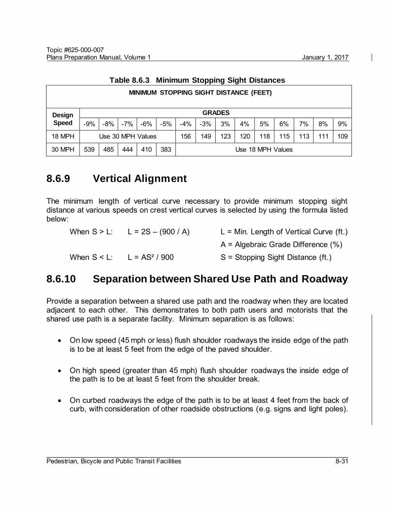
Table 8.6.3 Minimum Stopping Sight Distances
MINIMUM STOPPING SIGHT DISTANCE (FEET)
Design
Speed
GRADES
-9% -8% -7% -6% -5% -4% -3% 3% 4% 5% 6% 7% 8% 9%
18 MPH Use 30 MPH Values 156 149 123 120 118 115 113 111 109
30 MPH 539 485 444 410 383 Use 18 MPH Values
8.6.9 Vertical Alignment
The minimum length of vertical curve necessary to provide minimum stopping sight distance at various speeds on crest vertical curves is selected by using the formula listed below: When S > L: L = 2S – (900 / A) L = Min. Length of Vertical Curve (ft.) A = Algebraic Grade Difference (%) When S < L: L = AS² / 900 S = Stopping Sight Distance (ft.)
8.6.10 Separation between Shared Use Path and Roadway
Provide a separation between a shared use path and the roadway when they are located adjacent to each other. This demonstrates to both path users and motorists that the shared use path is a separate facility. Minimum separation is as follows:
On low speed (45 mph or less) flush shoulder roadways the inside edge of the path is to be at least 5 feet from the edge of the paved shoulder.
On high speed (greater than 45 mph) flush shoulder roadways the inside edge of the path is to be at least 5 feet from the shoulder break.
On curbed roadways the edge of the path is to be at least 4 feet from the back of curb, with consideration of other roadside obstructions (e.g. signs and light poles).

Topic #625-000-007 Plans Preparation Manual, Volume 1 January 1, 2017
Pedestrian, Bicycle and Public Transit Facilities 8-32
8.6.11 Path Railings
Provide railings or fences as indicated in Section 8.8.
8.6.12 Lighting
Lighting for shared use paths is important and should be considered where riding at night is expected, such as paths serving college students or commuters. Lighting should also be considered through underpasses or tunnels. Lighting standards are provided in Table 7.3.1 of this Volume.
8.6.13 Signing, Pavement Marking, and Signalization
The MUTCD regulates the design and use of all traffic control devices on shared use paths. Figure 8.6.1 provides the minimum criteria for the placement of signs along or over a shared use path. Signs on shared use paths should follow the dimensions provided in Table 9B-1 Bicycle Sign and Plaque Sizes, MUTCD. Guidance on the placement of stop or yield lines and crosswalks on roadways intersecting with shared use paths is provided in the MUTCD, Part 3.
Figure 8.6.1 Sign Placement on Shared Use Paths
Consult the Design Standards and MUTCD for all signage, pavement markings and signals, especially at railroad crossings and roadway intersections.
Topic #625-000-007 Plans Preparation Manual, Volume 1 January 1, 2017
Pedestrian, Bicycle and Public Transit Facilities 8-33
8.7 Bridges, Overpasses, and Underpasses
A bridge, overpass, or underpass may be necessary to provide pedestrian and bicycle continuity to sidewalks, bicycle lanes and shared use paths. Provide accommodations for bicyclists on pedestrian bridges; i.e., provide an alternative to stairs.
8.7.1 Design Criteria
Design overpasses and bridges in accordance with the criteria established below: 1. FDOT Structures Design Guidelines – Chapter 10. 2. Section 8.2 of this Volume.
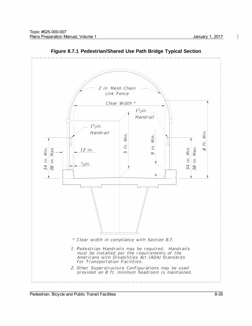
3. The minimum clear width for new FDOT pedestrian bridges is: a. On a pedestrian structure - 8 feet. b. On a shared use path structure - 12 feet. c. If the approach sidewalk or path is wider than these minimums, the clear width
of the structure should match the approach width. The desirable clear width should include an additional 2-foot wide clear area on each side.
4. Vertical clearance criteria is found in Table 2.10.1 of this Volume. Account for future widening of the roadway below when determining required lateral offset.
5. Ramps a. Comply with ADA requirements. Additional information is provided on the
website: Production Support Office - Accessibility Issues (ADA) Website b. Ramps (routes with grades >5%) should be provided at all pedestrian
separation structures. Consider providing stairways in addition to ramps. c. Design ramps with the least possible grade, but in no case more than 8.33%
with a maximum 30-inch rise. Provide level landings that are 5-feet long at the top, intermediate, and bottom portions of the ramp.
d. Provide full-length pedestrian ADA handrails on both sides of pedestrian ramps. 6. Railing and Fencing
a. Provide railing and fencing options in accordance with the SDG Chapter 10. b. Refer to Chapter 4, Figures 4.4.9 and 4.4.10 of this Volume for vehicular
fencing options. c. Provide full or partial screening on pedestrian bridges crossing FDOT right of
way in order to reduce the likelihood of objects being dropped or thrown onto
Topic #625-000-007 Plans Preparation Manual, Volume 1 January 1, 2017
Pedestrian, Bicycle and Public Transit Facilities 8-34
the roadway below. See Figure 8.7.1 for example of full screening.
d. Pedestrian bridges on FDOT right of way but not crossing FDOT right of way are not required to be screened.
e. Check with local authorities for guidance on screening for FDOT pedestrian bridges crossing local rights of way.
f. The use of chain link fence on ramps of the pedestrian bridges will be determined on a project-by-project basis.
Modification for Non-Conventional Projects:
Add the following sentence:
g. When fencing is required, the limits of fencing is from the beginning of the approach slab at Begin Bridge to the end of the approach slab at End Bridge, unless otherwise indicated in the RFP.
See Chapter 26 of this Volume for review requirements based on pedestrian bridge structure category.
Pedestrian underpasses are generally undesirable; however, if one is provided, the geometrics and lighting requirements should be discussed with the Department Project Manager and the District Pedestrian/Bicycle Coordinator. Local law enforcement personnel may need to be consulted to assure public safety, emergency accessibility and other desirable features.
Topic #625-000-007 Plans Preparation Manual, Volume 1 January 1, 2017
Pedestrian, Bicycle and Public Transit Facilities 8-35
Figure 8.7.1 Pedestrian/Shared Use Path Bridge Typical Section
Topic #625-000-007 Plans Preparation Manual, Volume 1 January 1, 2017
Pedestrian, Bicycle and Public Transit Facilities 8-36
8.7.2 Prefabricated Steel Truss Bridges on FDOT Projects
In many situations it makes good engineering and economic sense to utilize prefabricated steel truss bridges for pedestrian crossings. These bridges can be stand-alone structures or a hybrid structure with adjoining spans of other types (FIB, deck slab, steel I-girder, etc.). The provisions of this article apply only to the spans on a bridge that are comprised of prefabricated steel trusses. The term steel truss bridge as applied in this article refers only to stand-alone steel truss structures or to the steel truss spans of a hybrid bridge structure.
The Department may elect to use prefabricated truss bridges on FDOT projects if the following conditions are met:
1. The steel truss span lies within a tangent horizontal alignment.
2. The maximum length of the steel truss span does not exceed 200 feet.
3. The width of the steel truss span is constant.
4. The steel truss span supports have a skew angle not to exceed 20°.
When these criteria are not met provide a complete set of bridge details in the plans.
Modification for Non-Conventional Projects:
Delete PPM 8.7.2 and replace with the following:
8.7.2 Prefabricated Steel Truss Bridges on FDOT Projects
Prefabricated steel truss bridges can be stand-alone structures or a hybrid structure with adjoining spans of other types (FIB, deck slab, steel I-girder, etc.). The provisions of this article apply only to the spans on a bridge that are comprised of prefabricated steel trusses. The term steel truss bridge as applied in this article refers only to stand-alone steel truss structures or to the steel truss spans of a hybrid bridge structure.
See RFP for requirements.

Topic #625-000-007 Plans Preparation Manual, Volume 1 January 1, 2017
Pedestrian, Bicycle and Public Transit Facilities 8-37
8.7.2.1 Qualification of Prefabricated Steel Truss Pedestrian Bridge Producers
Use prefabricated steel truss pedestrian bridges from providers included on the Department’s List of Qualified Metal Fabrication Facilities. For information on the facility qualification process see Articles 11.1.5 and 11.1.6 of the FDOT Materials Manual.
8.7.2.2 Design and Detailing Responsibilities
The project Engineer of Record (EOR) is responsible for the design and detailing of the steel truss bridge substructure and foundation including end bents, piers, pile foundations, and/or spread footings. The project EOR is also responsible for the design and detailing of approach structures (non-steel truss bridge spans, walls, ramps, steps, approach slabs, etc.).
The Contractor’s EOR is responsible for the design and detailing of the steel truss bridge superstructure including trusses, deck, bridge railing, floor beams, bridge joints, bearing assemblies and anchor bolts.
Modification for Non-Conventional Projects:
Delete PPM 8.7.2.2 and replace with the following:
8.7.2.2 Design and Detailing Responsibilities
The Engineer of Record (EOR) is responsible for the design and detailing of the steel truss bridge foundation, substructure and superstructure. The EOR is also responsible for design and detailing of approach structures (non-steel truss bridge spans, walls, ramps, steps, approach slabs, etc.). The steel truss bridge superstructure including trusses, deck, bridge railing, floor beams, bridge joints, bearing assemblies and anchor bolts must be included as part of the superstructure component submittal.
Topic #625-000-007 Plans Preparation Manual, Volume 1 January 1, 2017
Pedestrian, Bicycle and Public Transit Facilities 8-38
8.7.2.3 Plans Development
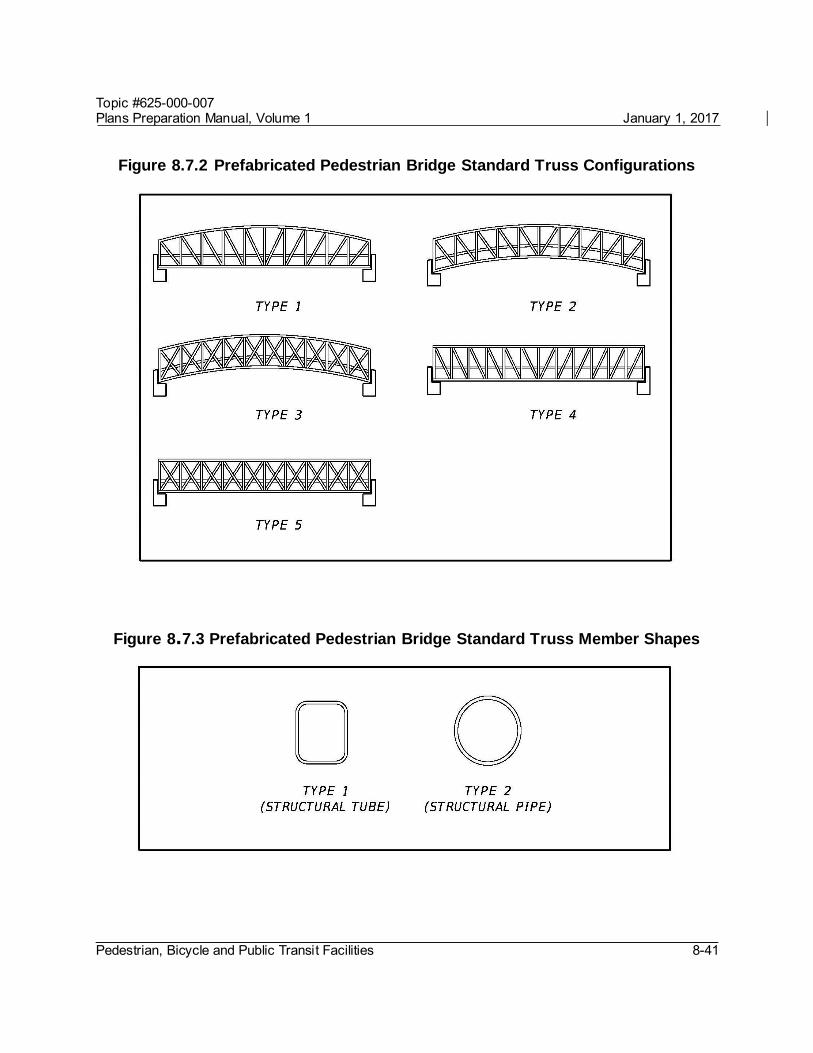
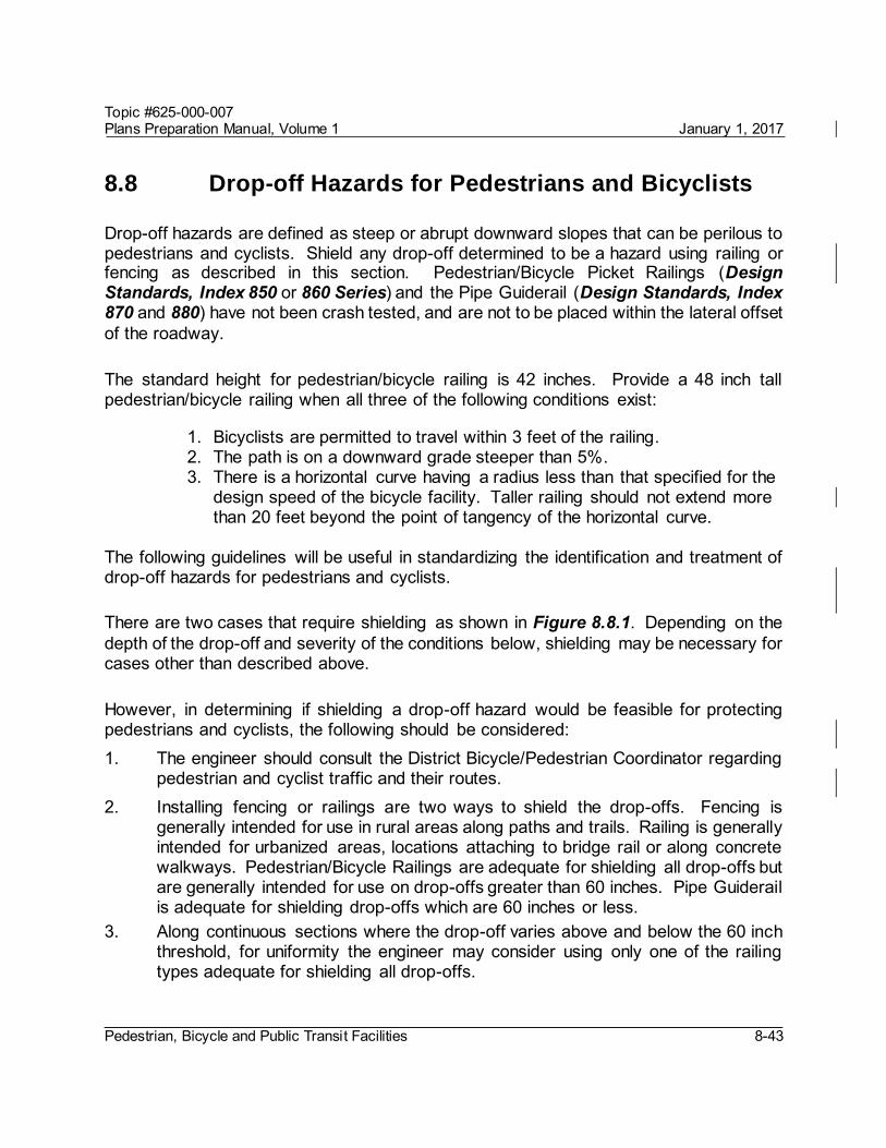
To allow equal opportunity for all qualified pedestrian bridge producers to participate, the pedestrian bridge plans should have the flexibility to accommodate multiple alternate superstructure designs. When a prefabricated steel truss pedestrian bridge is warranted, adhere to the following procedure when developing the plans: 1. Using Figures 8.7.2, 8.7.3, and 8.7.4, coordinate with the District Project Manager
to select allowable truss configurations, truss member shapes, and bridge cross sections. A box truss bridge cross-section is required for spans greater than 150 feet. If project specific aesthetic requirements warrant the use of truss configurations not included in Figure 8.7.2 the project EOR can specify additional truss configurations. However, a minimum of two steel truss pedestrian bridge producers must be capable of satisfying the aesthetic requirements.
2. Develop a Plan and Elevation sheet and Bridge Typical Section to be submitted with the BDR/30% plans.
3. After the BDR/30% plans have been approved, send out a Prefabricated Pedestrian Bridge Invitation to Participate (ITP) to all prefabricated pedestrian steel truss bridge producers on the Department’s List of Qualified Fabrication Facilities. Send the ITP through registered mail with return receipt to confirm delivery. Contact information for all qualified producers can be found at the following web address: http://www.dot.state.fl.us/statematerialsoffice/quality/programs/qualitycontr
ol/materialslistings/postjuly2002.shtm
The ITP is intended to solicit qualified producers for information required to design the foundation and substructure of the steel truss pedestrian bridge. The ITP cover letter should contain the following elements with links to websites as appropriate and applicable:
Introduction with brief project description Project Requirements o Design Specifications Requirements o Construction Specifications Requirements o Design Standards Requirements o Bridge Typical Section o Allowable Truss Options o Painting Requirements
Topic #625-000-007 Plans Preparation Manual, Volume 1 January 1, 2017
Pedestrian, Bicycle and Public Transit Facilities 8-39
o Pedestrian Fence/Railing Requirements o Vehicular Loading Requirements o Project Specific Aesthetic Requirements o Project Geometry including Vertical Clearance Requirements for Each Span
Participation Requirements Submittal Requirements
Include the following items in the ITP package:
Hard copy: o Invitation to Participate Cover Letter o Project Location Map o Plan and Elevation o Bridge Typical Section and Pedestrian Fence Concept o Pedestrian Bridge Data Sheet
Electronic files: o PDF file with all of the above o Pedestrian Bridge Data Sheet in CADD format
For a sample Prefabricated Pedestrian Bridge ITP complete with all hard copy attachments see Exhibit 8-A. To aid plan development CADD cells for the Pedestrian Bridge Data Sheet and Plan and Elevation sheet (2 of 2) are available in the FDOT Structures Cell Library. For the current FDOT Engineering/CADD Systems Software downloads follow the link below:
http://www.dot.state.fl.us/ecso/downloads/software/software.shtm
4. Upon delivery the pedestrian bridge, producers must acknowledge receipt of the ITP package.
5. In order to be eligible to participate in the project the pedestrian bridge producers must provide a completed Pedestrian Bridge Data Sheet as outlined in the ITP on or before the specified due date (prior to 60% plans submittal). The completed Data Sheets must be electronically signed and sealed by the pedestrian bridge producer’s EOR for inclusion in the final plan set. The project EOR assigns a unique sheet number to each data sheet. The sheet numbers will be identified with the prefix BP (e.g., BP-1, BP-2, BP-#) and the data sheets will be placed at the end of the numbered sequence of the bridge plans. This will allow the Pedestrian Bridge Data Sheets to have independent sheet numbers as plan development progresses.

Topic #625-000-007 Plans Preparation Manual, Volume 1 January 1, 2017
Pedestrian, Bicycle and Public Transit Facilities 8-40
6. After all ITP responses are received the project EOR must design and detail the foundation and substructure to accommodate the superstructure designs of all eligible pedestrian bridge producers. The design must envelope the most extreme loading conditions and geometry of all alternates.
7. A Public Interest Finding is required for Federal Aid projects when only one Interest for Participation letter is received.
8. Include the following notes in the plans: Eligible Steel Truss Pedestrian Bridge Producers
Included in this plan set are Pedestrian Bridge Data Sheets submitted by bridge producers eligible to participate in this project. Producers who failed to submit a data sheet are excluded from participation. No Cost Savings Initiative Proposal will be accepted for the truss superstructure portion of the project. Contact information for the eligible producers is included in the data sheet.
Shop Drawing Submittal Prior to fabrication the Contractor’s EOR must submit signed and sealed superstructure shop drawings, technical specifications, and design calculations to the Engineer for review and approval.
9. Include the following Pay Item note in the plans: Prefabricated Steel Truss Pedestrian Bridge Span
Prefabricated Steel Truss Pedestrian Bridge Span will be paid for at the contract unit price per square foot of deck area under Pay Item No. 460-7 Prefabricated Steel Truss Pedestrian Bridge, SF. This pay item includes furnishing and installing the prefabricated steel truss pedestrian bridge superstructure including steel trusses, floor system, deck, bearing assemblies, deck joints, and bridge railing/fencing. Payment for this pay item is based on the plan quantity. Portions of pedestrian bridge outside the limits of the steel truss span are paid for under individual pay items.
Topic #625-000-007 Plans Preparation Manual, Volume 1 January 1, 2017
Pedestrian, Bicycle and Public Transit Facilities 8-41
Figure 8.7.2 Prefabricated Pedestrian Bridge Standard Truss Configurations
Figure 8.7.3 Prefabricated Pedestrian Bridge Standard Truss Member Shapes

Topic #625-000-007 Plans Preparation Manual, Volume 1 January 1, 2017
Pedestrian, Bicycle and Public Transit Facilities 8-42
Figure 8.7.4 Prefabricated Pedestrian Standard Bridge Cross-Sections
Modification for Non-Conventional Projects:
Delete PPM 8.7.2.3 and see RFP for requirements.
Topic #625-000-007 Plans Preparation Manual, Volume 1 January 1, 2017
Pedestrian, Bicycle and Public Transit Facilities 8-43
8.8 Drop-off Hazards for Pedestrians and Bicyclists
Drop-off hazards are defined as steep or abrupt downward slopes that can be perilous to pedestrians and cyclists. Shield any drop-off determined to be a hazard using railing or fencing as described in this section. Pedestrian/Bicycle Picket Railings (Design Standards, Index 850 or 860 Series) and the Pipe Guiderail (Design Standards, Index 870 and 880) have not been crash tested, and are not to be placed within the lateral offset of the roadway.
The standard height for pedestrian/bicycle railing is 42 inches. Provide a 48 inch tall pedestrian/bicycle railing when all three of the following conditions exist:
1. Bicyclists are permitted to travel within 3 feet of the railing. 2. The path is on a downward grade steeper than 5%. 3. There is a horizontal curve having a radius less than that specified for the
design speed of the bicycle facility. Taller railing should not extend more than 20 feet beyond the point of tangency of the horizontal curve.
The following guidelines will be useful in standardizing the identification and treatment of drop-off hazards for pedestrians and cyclists.
There are two cases that require shielding as shown in Figure 8.8.1. Depending on the depth of the drop-off and severity of the conditions below, shielding may be necessary for cases other than described above.
However, in determining if shielding a drop-off hazard would be feasible for protecting pedestrians and cyclists, the following should be considered: 1. The engineer should consult the District Bicycle/Pedestrian Coordinator regarding
pedestrian and cyclist traffic and their routes. 2. Installing fencing or railings are two ways to shield the drop-offs. Fencing is
generally intended for use in rural areas along paths and trails. Railing is generally intended for urbanized areas, locations attaching to bridge rail or along concrete walkways. Pedestrian/Bicycle Railings are adequate for shielding all drop-offs but are generally intended for use on drop-offs greater than 60 inches. Pipe Guiderail is adequate for shielding drop-offs which are 60 inches or less.
3. Along continuous sections where the drop-off varies above and below the 60 inch threshold, for uniformity the engineer may consider using only one of the railing types adequate for shielding all drop-offs.
Topic #625-000-007 Plans Preparation Manual, Volume 1 January 1, 2017
Pedestrian, Bicycle and Public Transit Facilities 8-44
4. Care should be taken when using railing or fencing near intersections or driveways as they could obstruct the driver's line of sight. To reduce the need for railings, as a sidewalk or shared use path approaches an intersection, consider extending cross drains and side drains to minimize drop-offs.
Where Pedestrian/Bicycle Railing is used, the Department will cover the cost only for standard galvanized steel or standard aluminum railing. If the Local Agency desires a painted railing, they are required to provide the additional funding and commit to cover the maintenance cost. The Department will also only cover the cost of the standard Infill Panel Types shown in the Design Standards. If the Local Agency desires a railing having Custom Infill Panels which increases the cost over standard infill panels, they are required to provide the additional funding to cover this initial premium cost. In addition, a maintenance agreement will be needed to address the responsibilities associated with maintaining Custom Infill Panels.
Modification for Non-Conventional Projects:
Delete the above paragraph. See the RFP for requirements.
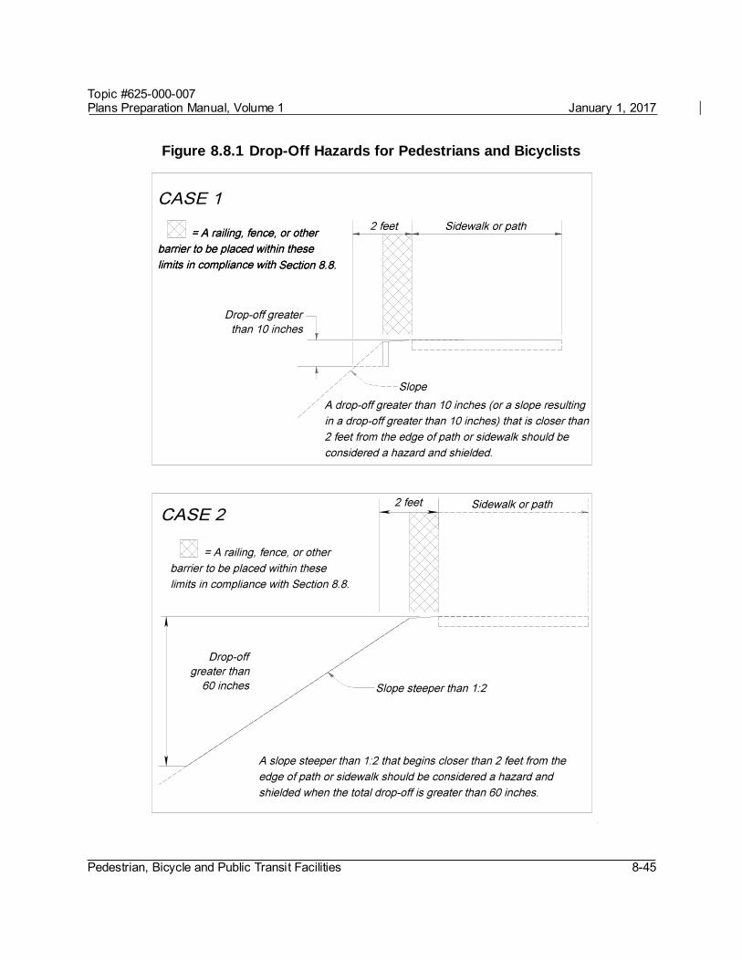
Topic #625-000-007 Plans Preparation Manual, Volume 1 January 1, 2017
Pedestrian, Bicycle and Public Transit Facilities 8-45
Figure 8.8.1 Drop-Off Hazards for Pedestrians and Bicyclists
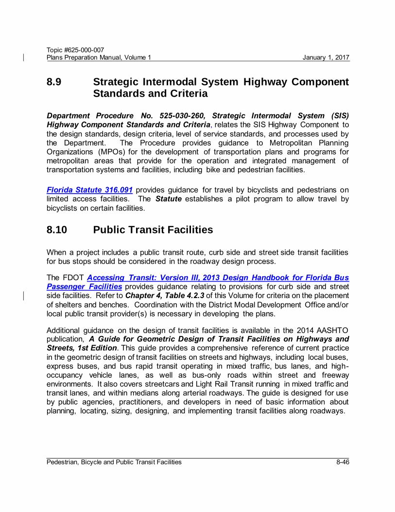
Topic #625-000-007 Plans Preparation Manual, Volume 1 January 1, 2017
Pedestrian, Bicycle and Public Transit Facilities 8-46
8.9 Strategic Intermodal System Highway Component Standards and Criteria
Department Procedure No. 525-030-260, Strategic Intermodal System (SIS) Highway Component Standards and Criteria, relates the SIS Highway Component to the design standards, design criteria, level of service standards, and processes used by the Department. The Procedure provides guidance to Metropolitan Planning Organizations (MPOs) for the development of transportation plans and programs for metropolitan areas that provide for the operation and integrated management of transportation systems and facilities, including bike and pedestrian facilities.
Florida Statute 316.091 provides guidance for travel by bicyclists and pedestrians on limited access facilities. The Statute establishes a pilot program to allow travel by bicyclists on certain facilities.
8.10 Public Transit Facilities
When a project includes a public transit route, curb side and street side transit facilities for bus stops should be considered in the roadway design process.
The FDOT Accessing Transit: Version III, 2013 Design Handbook for Florida Bus Passenger Facilities provides guidance relating to provisions for curb side and street side facilities. Refer to Chapter 4, Table 4.2.3 of this Volume for criteria on the placement of shelters and benches. Coordination with the District Modal Development Office and/or local public transit provider(s) is necessary in developing the plans.
Additional guidance on the design of transit facilities is available in the 2014 AASHTO publication, A Guide for Geometric Design of Transit Facilities on Highways and Streets, 1st Edition. This guide provides a comprehensive reference of current practice in the geometric design of transit facilities on streets and highways, including local buses, express buses, and bus rapid transit operating in mixed traffic, bus lanes, and high-occupancy vehicle lanes, as well as bus-only roads within street and freeway environments. It also covers streetcars and Light Rail Transit running in mixed traffic and transit lanes, and within medians along arterial roadways. The guide is designed for use by public agencies, practitioners, and developers in need of basic information about planning, locating, sizing, designing, and implementing transit facilities along roadways.

Topic #625-000-007 Plans Preparation Manual, Volume 1 January 1, 2017
Pedestrian, Bicycle and Public Transit Facilities 8-47
8.10.1 Boarding and Alighting Areas
Boarding and alighting areas help to create an accessible bus stop by providing a raised platform that is compatible with a bus that kneels or extends a ramp. A boarding and alighting area must have a firm, stable, and slip-resistant surface with a minimum clear length of 8 feet (measured perpendicular to the curb or roadway edge), and a minimum clear width of 5 feet (measured parallel to the roadway). Firm, stable, and slip resistant boarding and alighting areas are required if amenities such as benches or shelters are added to a bus stop. Boarding and alighting areas are not required at bus stops on flush shoulder roadways where only a bus stop sign is provided. Coordinate with the appropriate public transit provider(s) to determine compatibility with equipment and transit vehicles.
Modification for Non-Conventional Projects:
Delete the last sentence above and see the RFP for requirements.
The slope of the boarding and alighting area parallel to the roadway should be the same as the roadway. For drainage purposes, a maximum slope of 1:50 (2%) (measured perpendicular to the roadway) is allowed.
On flush shoulder roadways, the boarding and alighting area should be constructed at the shoulder break (or edge of shoulder pavement on roadways with a design speed of 45 mph or less) to create an accessible bus stop, as shown in Figures 8.10.1 and 8.10.2. The raised area provides a landing that is compatible with a bus that kneels or extends a ramp with a slope of 1:6 or less. Bus stops should be located in close proximity to existing intersections, and with sidewalk access. The boarding and alighting area is to: (1) Use a Type E curb and gutter (5” curb height) (2) Be connected to the sidewalk along the roadway; or to the roadway when no
sidewalk is present
A sidewalk and/or ramp provided with the boarding and alighting area must be a minimum of 5 feet in width; and the ramp must not exceed a slope of 1:12. A detectable warning is required where a sidewalk associated with a boarding and alighting area connects to the roadway at grade. Except for the area adjacent to the 5-inch curb, the areas surrounding the boarding and alighting area must be flush with the adjacent shoulder and side slopes and designed to be traversable by errant vehicles. On the upstream side of the landing, a maximum slope of 1:12 should be provided, and may be grass or a hardened surface. The boarding and alighting area (and ramp and level landing if needed) are to be constructed with 6-inch thick concrete.

Topic #625-000-007 Plans Preparation Manual, Volume 1 January 1, 2017
Pedestrian, Bicycle and Public Transit Facilities 8-48
Figure 8.10.1 Accessible Boarding and Alighting Area for Flush Shoulder Roadways with Connection to Roadway
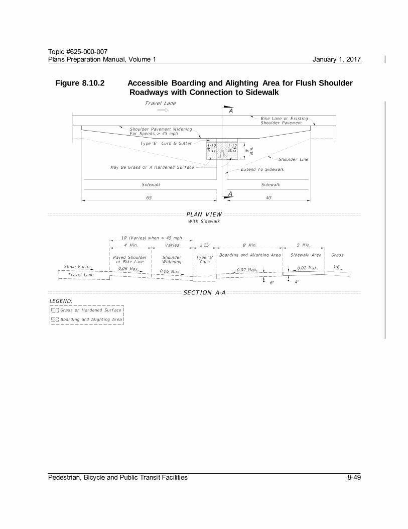
Topic #625-000-007 Plans Preparation Manual, Volume 1 January 1, 2017
Pedestrian, Bicycle and Public Transit Facilities 8-49
Figure 8.10.2 Accessible Boarding and Alighting Area for Flush Shoulder Roadways with Connection to Sidewalk

Topic #625-000-007 Plans Preparation Manual, Volume 1 January 1, 2017
Pedestrian, Bicycle and Public Transit Facilities 8-50
8.10.2 Street-Side Facilities
Bus stop locations can be categorized as far-side, near-side and midblock stops. Bus stops may be designed with a bus bay or pullout to allow buses to pick up and discharge passengers in an area outside of the travel lane. This design feature allows traffic to flow freely without the obstruction of stopped buses. See Figure 8.10.3 for typical details for the bus stop and bus bay categories. Chapter 2 of the Accessing Transit Handbook provides additional information for each facility. The greater distance placed between waiting passengers and the travel lane increases safety at a stop. Bus bays are encouraged on roadways with high operating speeds, such as roads that are part of the Urban Principal Arterial System. For a particular bus stop, a high frequency of crashes involving buses is a good indicator for the need of a bus bay. Bus bays are classified as closed, open or bulbs. Illustrations for various bus bay configurations are provided in the Accessing Transit Handbook on the Public Transit Office website. At a specific location, a balance must be obtained based on the designer's judgment and input from the applicable transit agencies. In locations where the traffic volumes exceed 1,000 vehicles per hour per lane, it is difficult to maneuver the bus into the bay and back into the travel lane. Incorporating an acceleration distance, signal priority, or a far-side (rather than near-side or midblock) placement, are potential solutions when traffic volumes exceed 1,000 vehicles per hour per lane.
The total length of the bus bay should allow room for an entrance taper, a stopping area, and an exit taper as a minimum. However, in some cases it may be appropriate to consider providing acceleration and deceleration lanes depending on the volume and speed of the through traffic. This decision should be based upon site specific conditions. Accessing Transit Handbook provides detailed bus bay dimensions for consideration when right of way is unlimited and access points are limited.
Topic #625-000-007 Plans Preparation Manual, Volume 1 January 1, 2017
Pedestrian, Bicycle and Public Transit Facilities 8-51
8.10.3 Exclusive Transit Running Ways
The Typical Sections for Exclusive Transit Running Ways is a guide not a standard. This guide is intended to be a starting point for designing exclusive transit running ways. Case-by-case evaluation of sites and corridors is essential in producing design drawings that are feasible and effective. This guide presents conceptual typical sections for exclusive transit running ways that may see application in Florida. Typical section elements, general dimensions, analysis considerations, and intersection operations considerations are identified for the following scenarios:
Concurrent flow curb bus lanes Concurrent flow median bus lanes Contraflow bus lane on a one-way street Contraflow bus lane on a two-way street At-grade two-way busway on a two-way street At-grade reversible one-lane median busway on a two-way street At-grade exclusive busway in roadway right-of-way At-grade exclusive busway in separate right-of-way Exclusive bus street Shoulder-running bus lanes on an uninterrupted flow highway.
These scenarios are described in more detail in Typical Sections for Exclusive Transit Running Ways guide on the Public Transit Office website.
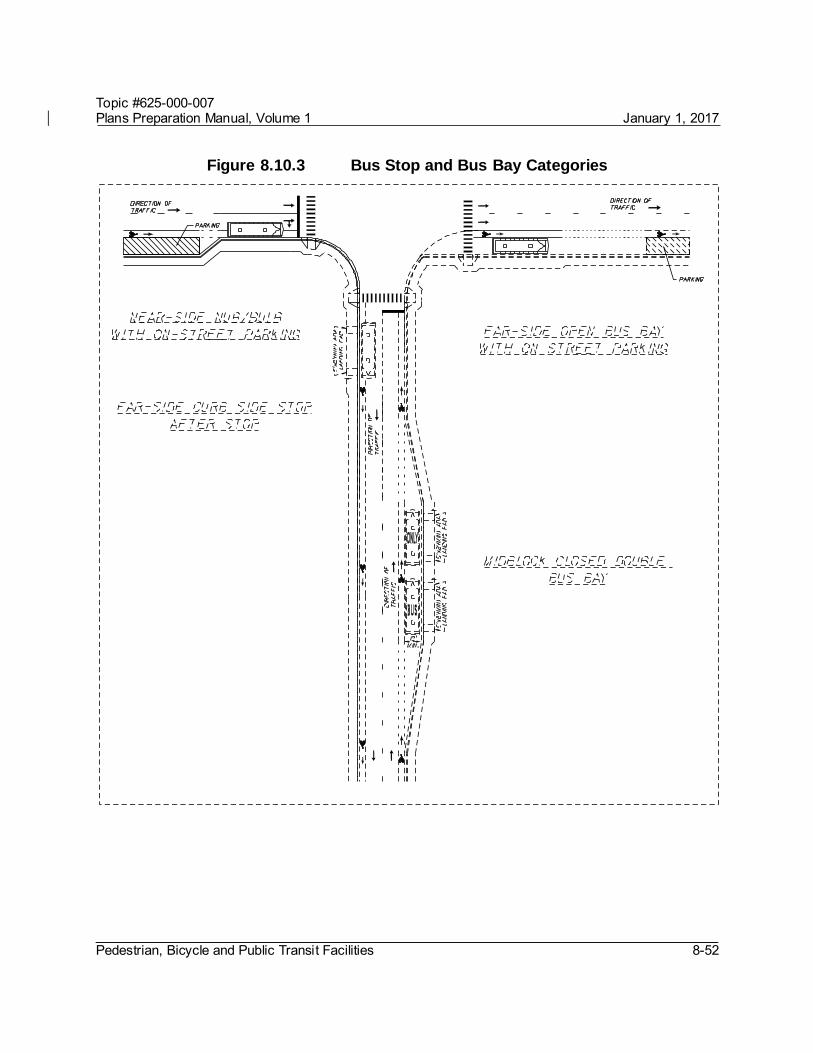
Topic #625-000-007 Plans Preparation Manual, Volume 1 January 1, 2017
Pedestrian, Bicycle and Public Transit Facilities 8-52
Figure 8.10.3 Bus Stop and Bus Bay Categories
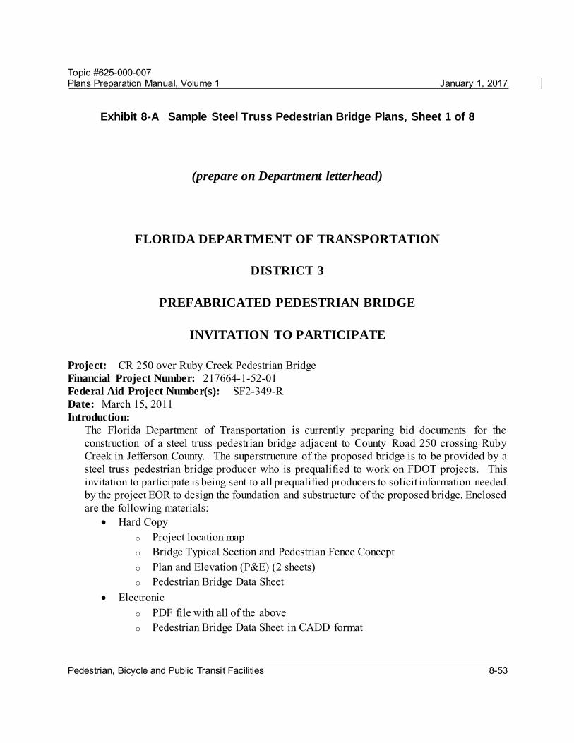
Topic #625-000-007 Plans Preparation Manual, Volume 1 January 1, 2017
Pedestrian, Bicycle and Public Transit Facilities 8-53
Exhibit 8-A Sample Steel Truss Pedestrian Bridge Plans, Sheet 1 of 8
(prepare on Department letterhead)
FLORIDA DEPARTMENT OF TRANSPORTATION
DISTRICT 3
PREFABRICATED PEDESTRIAN BRIDGE
INVITATION TO PARTICIPATE
Project: CR 250 over Ruby Creek Pedestrian Bridge Financial Project Number: 217664-1-52-01 Federal Aid Project Number(s): SF2-349-R Date: March 15, 2011 Introduction:
The Florida Department of Transportation is currently preparing bid documents for the construction of a steel truss pedestrian bridge adjacent to County Road 250 crossing Ruby Creek in Jefferson County. The superstructure of the proposed bridge is to be provided by a steel truss pedestrian bridge producer who is prequalified to work on FDOT projects. This invitation to participate is being sent to all prequalified producers to solicit information needed by the project EOR to design the foundation and substructure of the proposed bridge. Enclosed are the following materials:
Hard Copy o Project location map o Bridge Typical Section and Pedestrian Fence Concept o Plan and Elevation (P&E) (2 sheets) o Pedestrian Bridge Data Sheet
Electronic o PDF file with all of the above o Pedestrian Bridge Data Sheet in CADD format

Topic #625-000-007 Plans Preparation Manual, Volume 1 January 1, 2017
Pedestrian, Bicycle and Public Transit Facilities 8-54
Exhibit 8-A Sample Steel Truss Pedestrian Bridge Plans, Sheet 2 of 8
Project Requirements: 1. Design Specifications: as specified in FDOT Structures Design Guidelines (SDG) Article
10.4. http://www.dot.state.fl.us/structures/StructuresManual/CurrentRelease/StructuresManual.shtm
2. Construction Specifications: FDOT Standard Specifications for Road and Bridge Construction, current edition. http://www.dot.state.fl.us/programmanagement/
3. Design Standards: FDOT Design Standards, current edition. http://www.dot.state.fl.us/rddesign/DesignStandards/Standards.shtm
4. Allowable Truss Options: All allowable Truss options are indicated on P&E sheet 2 of 2 (Attached).
5. Paint: Paint all structural steel in accordance with Sections 560 and 975 of the Specifications. Paint all structural steel with a high performance top coat system. The color of the finish coat must conform to Federal Standard No. 595, Color No. 36622.
6. Pedestrian Fence: Bridge Fence consistent with bridge rail concept and SDG Article 10.12.
7. Vehicular Loading: Vehicular Loading per AASHTO LRFD Guide Specifications for the Design of Pedestrian Bridges is not required.
8. Geometry: For project geometry see attached P&E sheets.
Participation:
To be eligible to participate on this project pedestrian bridge producers must: Acknowledge receipt of this ITP Be on the FDOT List of Qualified Fabrication Facilities. Submit a response to this ITP on or before June 10, 2011 to the project EOR.
Submittal:
Provide completed pedestrian bridge data sheet as follows: Bearing Plate Dimensions Table – for each span provide bearing dimensions as shown
to the nearest 1/8th inch.

Topic #625-000-007 Plans Preparation Manual, Volume 1 January 1, 2017
Pedestrian, Bicycle and Public Transit Facilities 8-55
Exhibit 8-A Sample Steel Truss Pedestrian Bridge Plans, Sheet 3 of 8
Bearing Plate Locations & Bridge Seat Elevations Table – for each substructure unit provide dimensions as shown to the nearest 1/8th inch and bridge seat elevation to the nearest 0.001 feet.
Bridge Reactions Table – for each span provide loads as indicated to the nearest 0.1 kip.
Company Contact Information Table – in the contact information block provide company name, address, contact person, phone number, and e-mail address.
Florida PE Seal and Signature – provide seal and signature of Florida PE responsible for the work.
Submit response to:
John Doe, PE XYZ Engineers, Inc. 123 East Main Street Tampa, Florida 33607
By submitting a response to this invitation to participate the pedestrian bridge producer is agreeing to satisfy all project requirements listed above if selected.
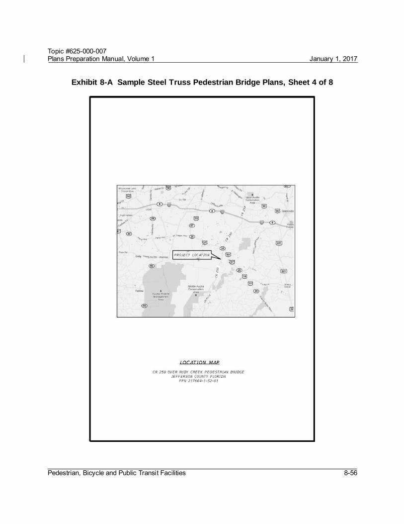
Topic #625-000-007 Plans Preparation Manual, Volume 1 January 1, 2017
Pedestrian, Bicycle and Public Transit Facilities 8-56
Exhibit 8-A Sample Steel Truss Pedestrian Bridge Plans, Sheet 4 of 8

Topic #625-000-007 Plans Preparation Manual, Volume 1 January 1, 2017
Pedestrian, Bicycle and Public Transit Facilities 8-57
Exhibit 8-A Sample Steel Truss Pedestrian Bridge Plans, Sheet 5 of 8

Topic #625-000-007 Plans Preparation Manual, Volume 1 January 1, 2017
Pedestrian, Bicycle and Public Transit Facilities 8-58
Exhibit 8-A Sample Steel Truss Pedestrian Bridge Plans, Sheet 6 of 8

Topic #625-000-007 Plans Preparation Manual, Volume 1 January 1, 2017
Pedestrian, Bicycle and Public Transit Facilities 8-59
Exhibit 8-A Sample Steel Truss Pedestrian Bridge Plans, Sheet 7 of 8

Topic #625-000-007 Plans Preparation Manual, Volume 1 January 1, 2017
Pedestrian, Bicycle and Public Transit Facilities 8-60
Exhibit 8-A Sample Steel Truss Pedestrian Bridge Plans, Sheet 8 of 8