CHAPTER 8 FLIGHT CONTROLS · OCT 2014 Chapter 8 Flight Controls Page 8.1 CHAPTER 8 FLIGHT CONTROLS...
72
CHAPTER 8 FLIGHT CONTROLS Section Title Page 8.000 Flight Controls . . . . . . . . . . . . . . . . . . . . . . . . . . . . . . . . . . . . . . . . . . . . 8.1 8.001 Introduction . . . . . . . . . . . . . . . . . . . . . . . . . . . . . . . . . . . . . . . . . . . . 8.1 8.002 Description . . . . . . . . . . . . . . . . . . . . . . . . . . . . . . . . . . . . . . . . . . . . . 8.1 8.100 Cyclic Controls . . . . . . . . . . . . . . . . . . . . . . . . . . . . . . . . . . . . . . . . . . . . 8.1 8.110 Cyclic Assembly . . . . . . . . . . . . . . . . . . . . . . . . . . . . . . . . . . . . . . . . . 8.1 8.111 Removal of Cyclic Assembly . . . . . . . . . . . . . . . . . . . . . . . . . . . . . . 8.1 8.112 Installation of Cyclic Assembly . . . . . . . . . . . . . . . . . . . . . . . . . . . . . 8.4 8.120 Cyclic Grip Assembly . . . . . . . . . . . . . . . . . . . . . . . . . . . . . . . . . . . . . 8.7 8.121 Removal of Cyclic Grip Assembly . . . . . . . . . . . . . . . . . . . . . . . . . . . 8.7 8.122 Installation of Cyclic Grip Assembly . . . . . . . . . . . . . . . . . . . . . . . . . 8.8 8.130 Cyclic Lateral (Right) Trim . . . . . . . . . . . . . . . . . . . . . . . . . . . . . . . . . . 8.10 8.131 Right Trim Spring Assembly Removal . . . . . . . . . . . . . . . . . . . . . . . . 8.10 8.132 Right Trim Spring Assembly Installation . . . . . . . . . . . . . . . . . . . . . . . 8.10 8.133 Right Trim Spring Replacement and Shimming . . . . . . . . . . . . . . . . . . 8.11 8.140 Cyclic Longitudinal (Fore-Aft) Elastic Trim Cord . . . . . . . . . . . . . . . . . . . 8.15 8.141 Longitudinal Trim Cord Removal . . . . . . . . . . . . . . . . . . . . . . . . . . . . 8.19 8.142 Longitudinal Trim Cord Installation . . . . . . . . . . . . . . . . . . . . . . . . . . 8.19 8.150 Cyclic Friction Assembly . . . . . . . . . . . . . . . . . . . . . . . . . . . . . . . . . . . 8.20 8.151 Cyclic Friction Adjustment . . . . . . . . . . . . . . . . . . . . . . . . . . . . . . . . 8.20 8.160 A121-7 Push-Pull Tube . . . . . . . . . . . . . . . . . . . . . . . . . . . . . . . . . . . . 8.21 8.161 A121-7 Push-Pull Tube Removal . . . . . . . . . . . . . . . . . . . . . . . . . . . 8.21 8.162 A121-7 Push-Pull Tube Inspection/Repair . . . . . . . . . . . . . . . . . . . . . 8.21 8.163 A121-7 Push-Pull Tube Sleeve Installation . . . . . . . . . . . . . . . . . . . . . 8.22 8.164 A121-7 Push-Pull Tube Sleeve Inspection . . . . . . . . . . . . . . . . . . . . . 8.22 8.165 A121-7 Push-Pull Tube Installation . . . . . . . . . . . . . . . . . . . . . . . . . . 8.23 8.200 Collective Control . . . . . . . . . . . . . . . . . . . . . . . . . . . . . . . . . . . . . . . . . . 8.25 8.210 Collective Stick Assembly . . . . . . . . . . . . . . . . . . . . . . . . . . . . . . . . . . 8.25 8.211 Collective Stick Removal . . . . . . . . . . . . . . . . . . . . . . . . . . . . . . . . . 8.25 8.212 Collective Stick Installation . . . . . . . . . . . . . . . . . . . . . . . . . . . . . . . 8.26 8.220 Collective Spring Assembly . . . . . . . . . . . . . . . . . . . . . . . . . . . . . . . . . 8.30 8.221 Collective Spring Removal . . . . . . . . . . . . . . . . . . . . . . . . . . . . . . . . 8.30 8.222 Collective Spring Installation . . . . . . . . . . . . . . . . . . . . . . . . . . . . . . 8.32 8.223 Collective Spring Adjustment for A038-1 thru -4 Assembly . . . . . . . . . 8.33 8.224 Collective Spring Adjustment for A038-5 and -6 Assembly . . . . . . . . . 8.34 OCT 2014 Chapter 8 Flight Controls Page 8.i
Transcript of CHAPTER 8 FLIGHT CONTROLS · OCT 2014 Chapter 8 Flight Controls Page 8.1 CHAPTER 8 FLIGHT CONTROLS...
CHAPTER 8
FLIGHT CONTROLS
Section Title Page
8.000 Flight Controls . . . . . . . . . . . . . . . . . . . . . . . . . . . . . . . . . . . . . . . . . . . . 8.18.001 Introduction . . . . . . . . . . . . . . . . . . . . . . . . . . . . . . . . . . . . . . . . . . . . 8.18.002 Description . . . . . . . . . . . . . . . . . . . . . . . . . . . . . . . . . . . . . . . . . . . . . 8.1
8.100 Cyclic Controls . . . . . . . . . . . . . . . . . . . . . . . . . . . . . . . . . . . . . . . . . . . . 8.18.110 Cyclic Assembly . . . . . . . . . . . . . . . . . . . . . . . . . . . . . . . . . . . . . . . . . 8.1
8.111 Removal of Cyclic Assembly . . . . . . . . . . . . . . . . . . . . . . . . . . . . . . 8.18.112 Installation of Cyclic Assembly . . . . . . . . . . . . . . . . . . . . . . . . . . . . . 8.4
8.120 Cyclic Grip Assembly . . . . . . . . . . . . . . . . . . . . . . . . . . . . . . . . . . . . . 8.78.121 Removal of Cyclic Grip Assembly . . . . . . . . . . . . . . . . . . . . . . . . . . . 8.78.122 Installation of Cyclic Grip Assembly . . . . . . . . . . . . . . . . . . . . . . . . . 8.8
8.130 Cyclic Lateral (Right) Trim . . . . . . . . . . . . . . . . . . . . . . . . . . . . . . . . . . 8.108.131 Right Trim Spring Assembly Removal . . . . . . . . . . . . . . . . . . . . . . . . 8.108.132 Right Trim Spring Assembly Installation . . . . . . . . . . . . . . . . . . . . . . . 8.108.133 Right Trim Spring Replacement and Shimming . . . . . . . . . . . . . . . . . . 8.11
8.140 Cyclic Longitudinal (Fore-Aft) Elastic Trim Cord . . . . . . . . . . . . . . . . . . . 8.158.141 Longitudinal Trim Cord Removal . . . . . . . . . . . . . . . . . . . . . . . . . . . . 8.198.142 Longitudinal Trim Cord Installation . . . . . . . . . . . . . . . . . . . . . . . . . . 8.19
8.150 Cyclic Friction Assembly . . . . . . . . . . . . . . . . . . . . . . . . . . . . . . . . . . . 8.208.151 Cyclic Friction Adjustment . . . . . . . . . . . . . . . . . . . . . . . . . . . . . . . . 8.20
8.160 A121-7 Push-Pull Tube . . . . . . . . . . . . . . . . . . . . . . . . . . . . . . . . . . . . 8.218.161 A121-7 Push-Pull Tube Removal . . . . . . . . . . . . . . . . . . . . . . . . . . . 8.218.162 A121-7 Push-Pull Tube Inspection/Repair . . . . . . . . . . . . . . . . . . . . . 8.218.163 A121-7 Push-Pull Tube Sleeve Installation . . . . . . . . . . . . . . . . . . . . . 8.228.164 A121-7 Push-Pull Tube Sleeve Inspection . . . . . . . . . . . . . . . . . . . . . 8.228.165 A121-7 Push-Pull Tube Installation . . . . . . . . . . . . . . . . . . . . . . . . . . 8.23
8.200 Collective Control . . . . . . . . . . . . . . . . . . . . . . . . . . . . . . . . . . . . . . . . . . 8.258.210 Collective Stick Assembly . . . . . . . . . . . . . . . . . . . . . . . . . . . . . . . . . . 8.25
8.211 Collective Stick Removal . . . . . . . . . . . . . . . . . . . . . . . . . . . . . . . . . 8.258.212 Collective Stick Installation . . . . . . . . . . . . . . . . . . . . . . . . . . . . . . . 8.26
8.220 Collective Spring Assembly . . . . . . . . . . . . . . . . . . . . . . . . . . . . . . . . . 8.308.221 Collective Spring Removal . . . . . . . . . . . . . . . . . . . . . . . . . . . . . . . . 8.308.222 Collective Spring Installation . . . . . . . . . . . . . . . . . . . . . . . . . . . . . . 8.328.223 Collective Spring Adjustment for A038-1 thru -4 Assembly . . . . . . . . . 8.338.224 Collective Spring Adjustment for A038-5 and -6 Assembly . . . . . . . . . 8.34
OCT 2014 Chapter 8 Flight Controls Page 8.i
CHAPTER 8
FLIGHT CONTROLS (Continued)
Section Title Page
8.225 Collective Friction Adjustment . . . . . . . . . . . . . . . . . . . . . . . . . . . . . 8.348.230 RPM Governor System . . . . . . . . . . . . . . . . . . . . . . . . . . . . . . . . . . . . 8.34A
8.231 Governor Controller Removal . . . . . . . . . . . . . . . . . . . . . . . . . . . . . . 8.34A8.232 Governor Controller Installation . . . . . . . . . . . . . . . . . . . . . . . . . . . . 8.34A8.233 Governor Assembly Removal . . . . . . . . . . . . . . . . . . . . . . . . . . . . . . 8.34A8.234 Governor Assembly Installation . . . . . . . . . . . . . . . . . . . . . . . . . . . . 8.34C8.239 Governor Troubleshooting . . . . . . . . . . . . . . . . . . . . . . . . . . . . . . . . 8.34C
8.300 Jackshaft and Support Struts . . . . . . . . . . . . . . . . . . . . . . . . . . . . . . . . . . 8.358.310 Jackshaft . . . . . . . . . . . . . . . . . . . . . . . . . . . . . . . . . . . . . . . . . . . . . . 8.35
8.311 Jackshaft Removal . . . . . . . . . . . . . . . . . . . . . . . . . . . . . . . . . . . . . 8.358.312 Jackshaft Installation . . . . . . . . . . . . . . . . . . . . . . . . . . . . . . . . . . . 8.35
8.320 Strut Assembly (Jackshaft Support) . . . . . . . . . . . . . . . . . . . . . . . . . . . 8.358.321 Strut Removal . . . . . . . . . . . . . . . . . . . . . . . . . . . . . . . . . . . . . . . . 8.358.322 Strut Installation . . . . . . . . . . . . . . . . . . . . . . . . . . . . . . . . . . . . . . . 8.38
8.400 Swashplate and Main Rotor Pitch Links . . . . . . . . . . . . . . . . . . . . . . . . . . . 8.398.410 Swashplate . . . . . . . . . . . . . . . . . . . . . . . . . . . . . . . . . . . . . . . . . . . . 8.39
8.411 Swashplate Removal . . . . . . . . . . . . . . . . . . . . . . . . . . . . . . . . . . . . 8.398.412 Swashplate Installation . . . . . . . . . . . . . . . . . . . . . . . . . . . . . . . . . . 8.408.413 (Reserved)8.414 (Reserved)8.415 (Reserved)8.416 Shimming Upper (Unflanged) Spherical Sleeve with Aluminum Ball . . . . 8.48
8.500 Tail Rotor Controls . . . . . . . . . . . . . . . . . . . . . . . . . . . . . . . . . . . . . . . . . . 8.488.510 Tail Rotor Pedals . . . . . . . . . . . . . . . . . . . . . . . . . . . . . . . . . . . . . . . . . 8.48
8.511 Tail Rotor Pedal Removal . . . . . . . . . . . . . . . . . . . . . . . . . . . . . . . . . 8.488.512 Tail Rotor Pedal Installation . . . . . . . . . . . . . . . . . . . . . . . . . . . . . . . 8.52
8.520 A317-1 Lower Bellcrank . . . . . . . . . . . . . . . . . . . . . . . . . . . . . . . . . . . 8.528.521 A317-1 Lower Forward Bellcrank Removal . . . . . . . . . . . . . . . . . . . . 8.528.522 A317-1 Lower Forward Bellcrank Installation . . . . . . . . . . . . . . . . . . . 8.53
8.530 A316-1 Upper Bellcrank . . . . . . . . . . . . . . . . . . . . . . . . . . . . . . . . . . . . 8.558.531 Bellcrank Removal . . . . . . . . . . . . . . . . . . . . . . . . . . . . . . . . . . . . . 8.558.532 Bellcrank Installation . . . . . . . . . . . . . . . . . . . . . . . . . . . . . . . . . . . . 8.55
8.540 A331-4 Intermediate Bellcrank . . . . . . . . . . . . . . . . . . . . . . . . . . . . . . . 8.568.541 Bellcrank Removal . . . . . . . . . . . . . . . . . . . . . . . . . . . . . . . . . . . . . 8.56
Page 8.ii Chapter 8 Flight Controls OCT 2014

OCT 2014 Chapter 8 Flight Controls Page 8.iii
CHAPTER 8
FLIGHT CONTROLS (Continued)
Section Title Page
8.542 Bellcrank Installation . . . . . . . . . . . . . . . . . . . . . . . . . . . . . . . . . . . . 8.578.550 A120-3 Aft Bellcrank . . . . . . . . . . . . . . . . . . . . . . . . . . . . . . . . . . . . . 8.57
8.551 Bellcrank Removal . . . . . . . . . . . . . . . . . . . . . . . . . . . . . . . . . . . . . 8.578.552 Bellcrank Installation . . . . . . . . . . . . . . . . . . . . . . . . . . . . . . . . . . . . 8.57
8.560 A031-1 Pitch Control . . . . . . . . . . . . . . . . . . . . . . . . . . . . . . . . . . . . . 8.578.561 Pitch Control Removal . . . . . . . . . . . . . . . . . . . . . . . . . . . . . . . . . . . 8.578.562 Pitch Control Installation . . . . . . . . . . . . . . . . . . . . . . . . . . . . . . . . . 8.57
8.570 Tail Rotor Pitch Links . . . . . . . . . . . . . . . . . . . . . . . . . . . . . . . . . . . . . . 8.588.571 Tail Rotor Pitch Link Removal . . . . . . . . . . . . . . . . . . . . . . . . . . . . . . 8.588.572 Tail Rotor Pitch Link Installation . . . . . . . . . . . . . . . . . . . . . . . . . . . . 8.58
8.600 A203 Yoke and A205 Fork Assemblies . . . . . . . . . . . . . . . . . . . . . . . . . . . 8.608.610 Bearing Removal . . . . . . . . . . . . . . . . . . . . . . . . . . . . . . . . . . . . . . . . . 8.60
8.615 C648-2 Bearing Installation . . . . . . . . . . . . . . . . . . . . . . . . . . . . . . . 8.608.620 A139-1 Bearing Installation . . . . . . . . . . . . . . . . . . . . . . . . . . . . . . . . . 8.608.630 B115-1 Bearing Installation . . . . . . . . . . . . . . . . . . . . . . . . . . . . . . . . . 8.628.640 Yoke and Fork Assembly Installation . . . . . . . . . . . . . . . . . . . . . . . . . . . 8.63

Intentionally Blank
Page 8.iv Chapter 8 Flight Controls OCT 2014
OCT 2014 Chapter 8 Flight Controls Page 8.1
CHAPTER 8
FLIGHT CONTROLS
8.000 Flight Controls
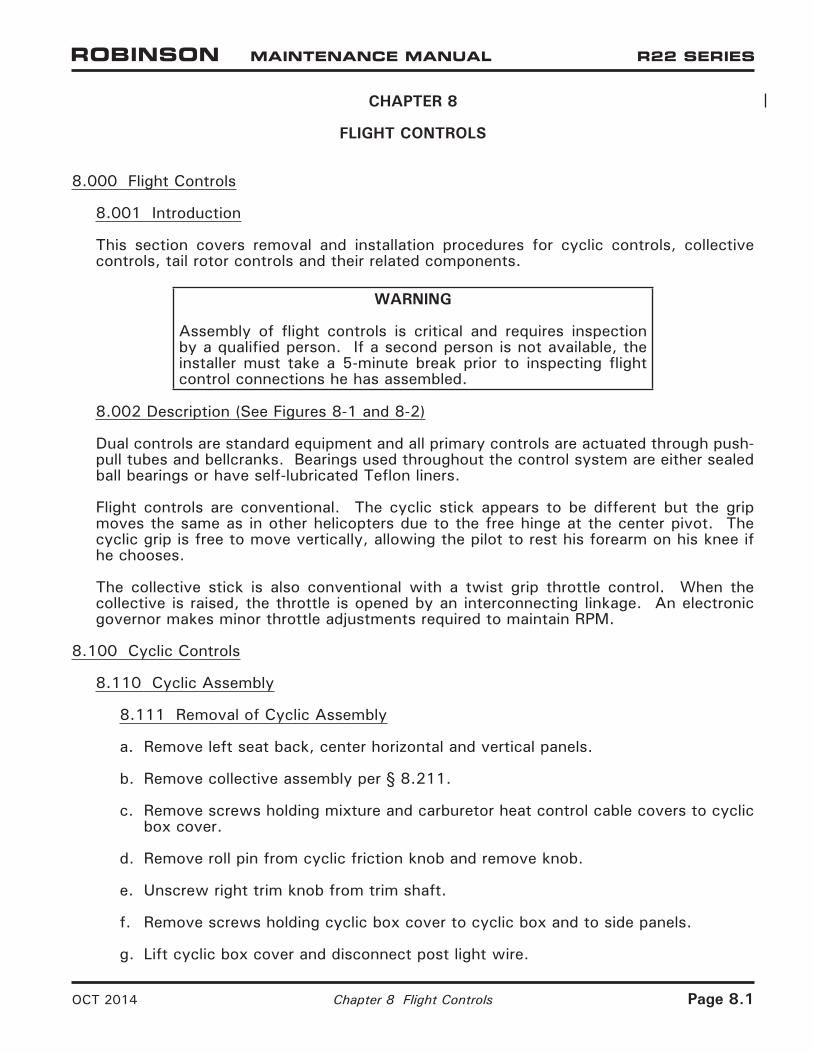
8.001 Introduction
This section covers removal and installation procedures for cyclic controls, collective controls, tail rotor controls and their related components.
WARNING
Assembly of flight controls is critical and requires inspection by a qualified person. If a second person is not available, the installer must take a 5-minute break prior to inspecting flight control connections he has assembled.
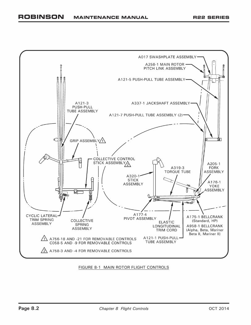
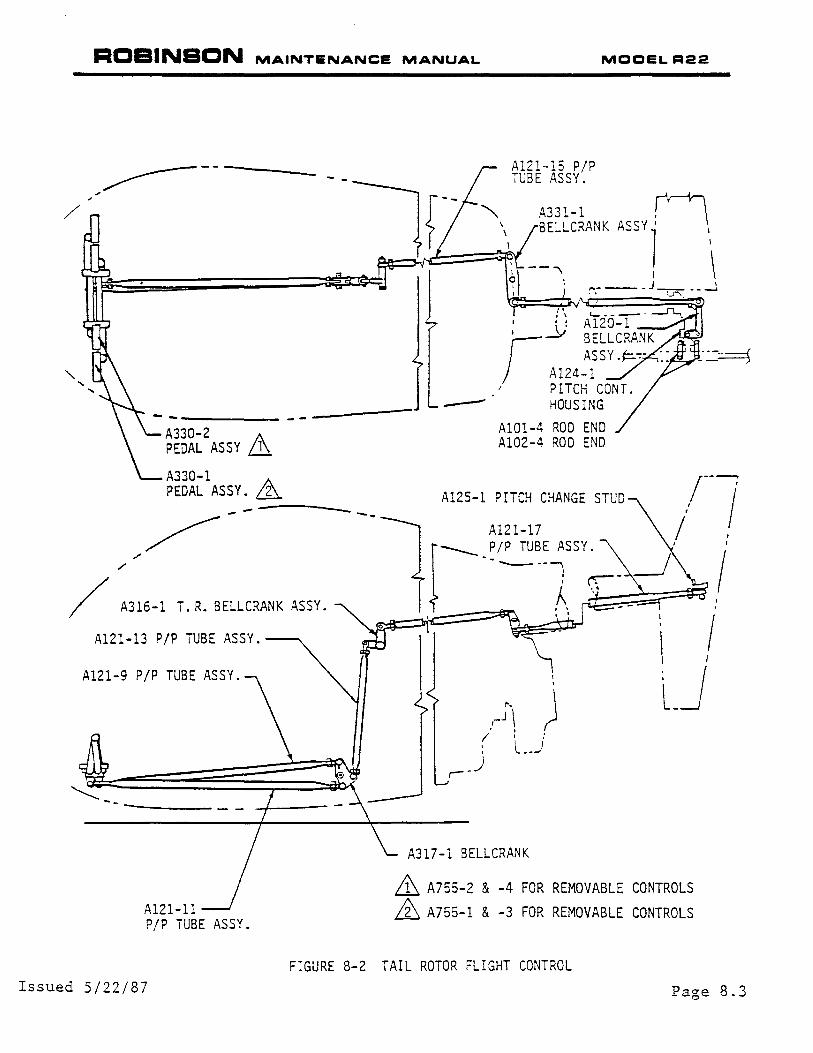
8.002 Description (See Figures 8-1 and 8-2)
Dual controls are standard equipment and all primary controls are actuated through push-pull tubes and bellcranks. Bearings used throughout the control system are either sealed ball bearings or have self-lubricated Teflon liners.
Flight controls are conventional. The cyclic stick appears to be different but the grip moves the same as in other helicopters due to the free hinge at the center pivot. The cyclic grip is free to move vertically, allowing the pilot to rest his forearm on his knee if he chooses.
The collective stick is also conventional with a twist grip throttle control. When the collective is raised, the throttle is opened by an interconnecting linkage. An electronic governor makes minor throttle adjustments required to maintain RPM.
8.100 Cyclic Controls
8.110 Cyclic Assembly
8.111 Removal of Cyclic Assembly
a. Remove left seat back, center horizontal and vertical panels.
b. Remove collective assembly per § 8.211.
c. Remove screws holding mixture and carburetor heat control cable covers to cyclic box cover.
d. Remove roll pin from cyclic friction knob and remove knob.
e. Unscrew right trim knob from trim shaft.
f. Remove screws holding cyclic box cover to cyclic box and to side panels.
g. Lift cyclic box cover and disconnect post light wire.
Page 8.2 Chapter 8 Flight Controls OCT 2014
FIGURE 8-1 MAIN ROTOR FLIGHT CONTROLS
RCBINSCN MAINTENANCE MANUAL MOOELR22
"' /
~--
/
A330-2 A PEDAL ASSY ill A330-l PEDAL ASSY. &_
.\ ~-------"....._ • · : Al20-1
r---_11 ~~~~~~-:~K ~= o---~~ j Al24-l
I PITCH CONT. ----- HOUSING
AlOl-4 ROD END Al02-4 ROO END
Al25-l PITCH CHANGE STUD
/ A316-! T. R. BELLCRANK ASSY.
Al21-13 P/P TUBE ASSY.
Al21-9 P/P TUBE ASSY.
~ -- ----
Al21-ll P/P TUBE ASSY.
Issued 5/22/87
)
A317-l BELLCRANK
~ A755-2 & -4 FOR REMOVABLE CONTROLS
~ A755-l & -3 FOR REMOVABLE CONTROLS
FIGURE 8-2 TAIL ROTOR FLIGHT CONTROL
Page 8.3
ROBINSON MAINTENANCE MANUAL MOOEL R22
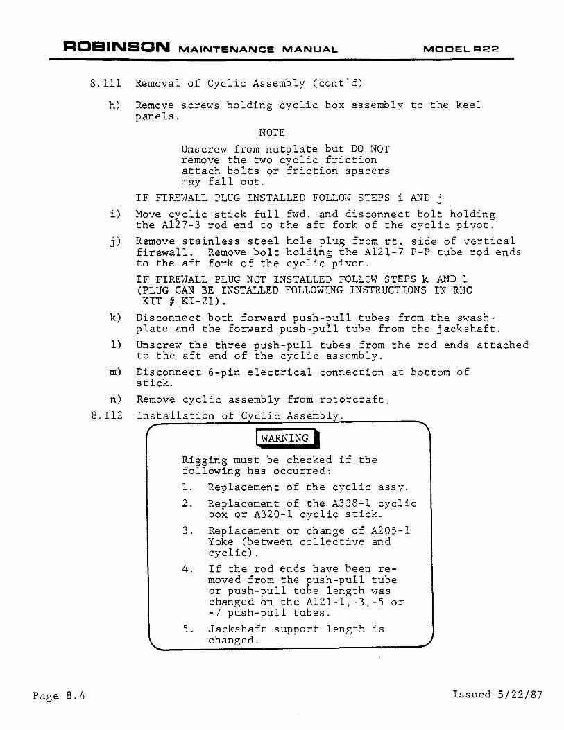
8.111 Removal of Cyclic Assembly (cont'd)
h) Remove screws holding cyclic box assembly to the keel panels.
i)
j)
k)
1)
m)
n)
8.112
NOTE
Unscrew from nutplate but DO NOT remove the two cyclic friction attach bolts or friction spacers may fall out.
IF FIREWALL PLUG INSTALLED FOLLO\.J STEPS i AND j
Move cyclic stick full fwd. and disconnect bolt holding the Al27-3 rod end to the aft fork of the cyclic pivot.
Remove stainless steel hole plug from rt. side of vertical firewall. Remove bolt holding the Al21-7 P-P tube rod ends to the aft fork of the cyclic pivot.
IF FIREWALL PLUG NOT INSTALLED FOLLOW STEPS k &~D 1 (PLUG CAN BE INSTALLED FOLLOWING INSTRUCTIONS IN RHC KIT II KI-21).
Disconnect both forward push-pull tubes from the swashplate and the forward push-pull tube from the jackshaft.
Unscrew the three push-pull tubes from the rod ends attached to the aft end of the cyclic assembly.
Disconnect 6-pin electrical connection at bottom of stick.
Remove cyclic assembly from rotorcraft,
Installation of Cyclic Assembl
I WARNING I Rigging must be checked if the following has occurred:
1. Replacement of the cyclic assy.
2. Replacement of the A338-l cyclic oox or A320-l cyclic stick.
3. Replacement or change of A205-l Yoke (between collective and cyclic).
4. If the rod ends have been removed from the push-pull tube or push-pull tube length was changed on the Al21-l,-3,-5 or -7 push-pull tubes.
5. Jackshaft support length is changed.
Page 8.4 Issued 5/22/87
ROBINSON MAINTENANCE MANUAL
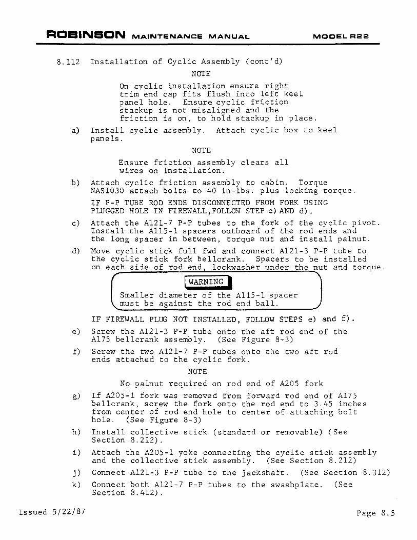
8.112 Installation of Cyclic Assembly (cont'd)
NOTE
On cyclic installation ensure right
MOCELR22
trim end cap fits flus·h into left keel panel hole. Ensure cyclic friction stackup is not misaligned and the friction is on, to hold stackup in place.
a) Install cyclic assembly. Attach cyclic box to keel panels.
NOTE
Ensure friction assembly clears all wires on installation.
b) Attach cyclic friction assembly to cabin. Torque NAS1030 attach bolts to 40 in-lbs. plus locking torque.
IF P-P TUBE ROD ENDS DISCONNECTED FROM FO~~ USING PLUGGED HOLE IN FIRE\.JALL, FOLLmv STEP c) AND d) .
c) Attach the Al21-7 P-P tubes to the fork of the cyclic pivot. Install the AllS-1 spacers outboard of the rod ends and the long spacer in between, torque nut and install palnut.
d) Move cyclic stick full fwd and connect Al21-3 P-P tube to the cyclic stick fork bellcrank. Spacers to be installed on each side of rod end, lockwasher under the nut and torque.
I WARNING I Smaller diameter of the AllS-1 spacer must be against the rod end ball.
IF FIREWALL PLUG NOT INSTALLED, FOLLOW STEPS e) and f)·
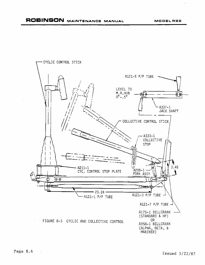
e) Screw the Al21-3 P-P tube onto the aft rod end of the Al75 bellcrank assembly. (See Figure 8-3)
f) Screw the two Al21-7 P-P tubes onto the two aft rod ends attached to the cyclic fork.
NOTE
No palnut required on rod end of A205 fork
g) If A205-l fork was removed from forward rod end of Al75 bellcrank, screw the fork onto the rod end to 3.45 inches from center of rod end hole to center of attaching bolt hole. (See Figure 8-3)
h) Install collective stick (standard or removable) (See Section 8.212).
i) Attach the A205-l yoke connecting the cyclic stick assembly and the collective stick assembly. (See Section 8.212)
j) Connect Al21-3 P-P tube to the jackshaft. (See Section 8.312)
k) Connect both Al21-7 P-P tubes to the swashplate. (See Section 8.412).
Issued 5/22/87 Page 8.5
ROBINSON MAINTENANCE MANUAL MOOELR22
Page 8.6
CYCLIC CONTROL STICK
Al21-5 P/P TUBE
LEVEL TO M.R.HUB 00-.50
A337-l JACK SHAFT
COLLECTIVE CONTROL STICK
~ ~£ = -=----:=----------~======~---- A211-l
CYC. CONTROL STOP PLATE
A333-l COLLECTIVE STOP
_______ , ____ 23.24 ________ __..
Al21-l P/P TUBE
FIGURE 8-3 CYCLIC AND COLLECTIVE CONTROL
Al21-7 P/P TUBE
A175-1 BELLCRANK (STANDARD & HP)
OR A958-1 BELLCRANK (ALPHA, BETA, & MARINER)
Issued 5/22/87
ROBINSON MAINTENANCE MANUAL MOCELR22
8.112 Installation of Cyclic Assembly (cont'd)
j) Install cyclic box cover.
1. Connect post lightwire and ty-rap clear of controls,
2. Insert right trim shaft through cover and install knob.
3. Attach power plant controls to the cyclic box cover.
4. Install cyclic box cover and tighten the attaching screws.
k) Install cyclic friction knob.
See Section 8.150 for adjusting cyclic friction assembly.
1) Move flight controls throughout complete travel. Verify no binding or clearance problems.
m) Rig flight controls per Section 10.000.
I WARNING I Ensure all jarnnuts and attaching hardware has been torqued per Section 1.300 Fastener Torques.
n) Install all seat backs and inspection covers.
8.120 Cyclic Grip Assembly (Standard or Removal)
8.121 Removal of Cyclic Grip Assembly.
This may be accomplished, if necessary, without removal of complete cyclic assembly from rotorcraft.
a) Remove bottom center inspection panel.
Issued 5/22/87
Disconnect 6-pin connector and use pin extractor to remove the pins from the connector.
Page 8.7
ROBINSON MAINTENANCE MANUAL MODEL R22
8.121 Removal of Cyclic Grip Assembly (cont'd)
b) Remove end cap from the cyclic grip pivot.
c) Remove cotter pin, nut and Al41-14 washer.
d) Gently tap cyclic grip shaft (DO NOT damage threads) and remove cyclic grip assembly from A320-l stick.
NOTE
DO NOT damage bearings in removal.
NOTE
The six wires are grouped into two sets of three wires each on the bottom right side of the cyclic stick with heat shrink around all six to prevent chafing.
e) Remove the heat shrink and attach two pieces of 0.032" or 0.020" safety wire. One piece of safety wire on one of the wires in each group. Pull each wire group out of the stick, but leave the two pieces of safety wire protruding from each end.
8.122 Installation of Cyclic Grip Assembly (Standard or Removable )
a) Cyclic grip assembly may be installed without removal of complete cyclic box assembly from rotorcraft.
NOTE
Mark wire numbers near pins for later re-installation.
1. Remove bottom center belly panel.
2. Remove pins from connector.
NOTE
Rigging check not required after cyclic grip installation.
b) Ensure rollpin is installed in the grip assembly. Heat shrink and two grommets should already be installed over the six wires coming out of the grip assembly.
Page 8.8 Issued 5/22/87
ROBINSON MAINTENANCE MANUAL MOOEL R22
8.122 Installation of Cyclic Grip Assembly (cont'd)
NOTE
The six wires are to be grouped into two sets of three wires each. One group will extend through the forward right side of the cyclic stick and the other will extend through the aft right side.
c) Using two pieces of safety wire extending from the top aft electrical hole in the cyclic, one through the bottom right forward side of the stick and the other through the bottom right aft side, stagger and tape three wires onto each safety wire. Carefully pull the safety wire and wires through the cyclic stick.
d) Attach heat shrink around all six wires and slide shrink tubing into stick as far as possible to prevent chafing.
e) Reinstall pins on each wire into proper position connector.
Housing Pin Location l 2 3 4 5
Standard Cyclic Wires 231 232 233 234 235
Removable Cyclic Wires 277 280 281 234 235
f) Reconnect the cyclic wiring connector.
6
236
236
g) Slide grip assembly into bearings in stick assembly. Install Al41-14 washer and castellated nut.
I CAUTION I Secure nut until there is no axial movement of bearings and cylic grip assembly. DO NOT overtighten assembly as it will damage the bearings.
h) Install cotter pin and end cap.
i) Install bottom rotorcraft inspection panels.
Issued 5/22/87 Page 8.9
ROBINSON MAINTENANCE MANUAL MOCEL R22
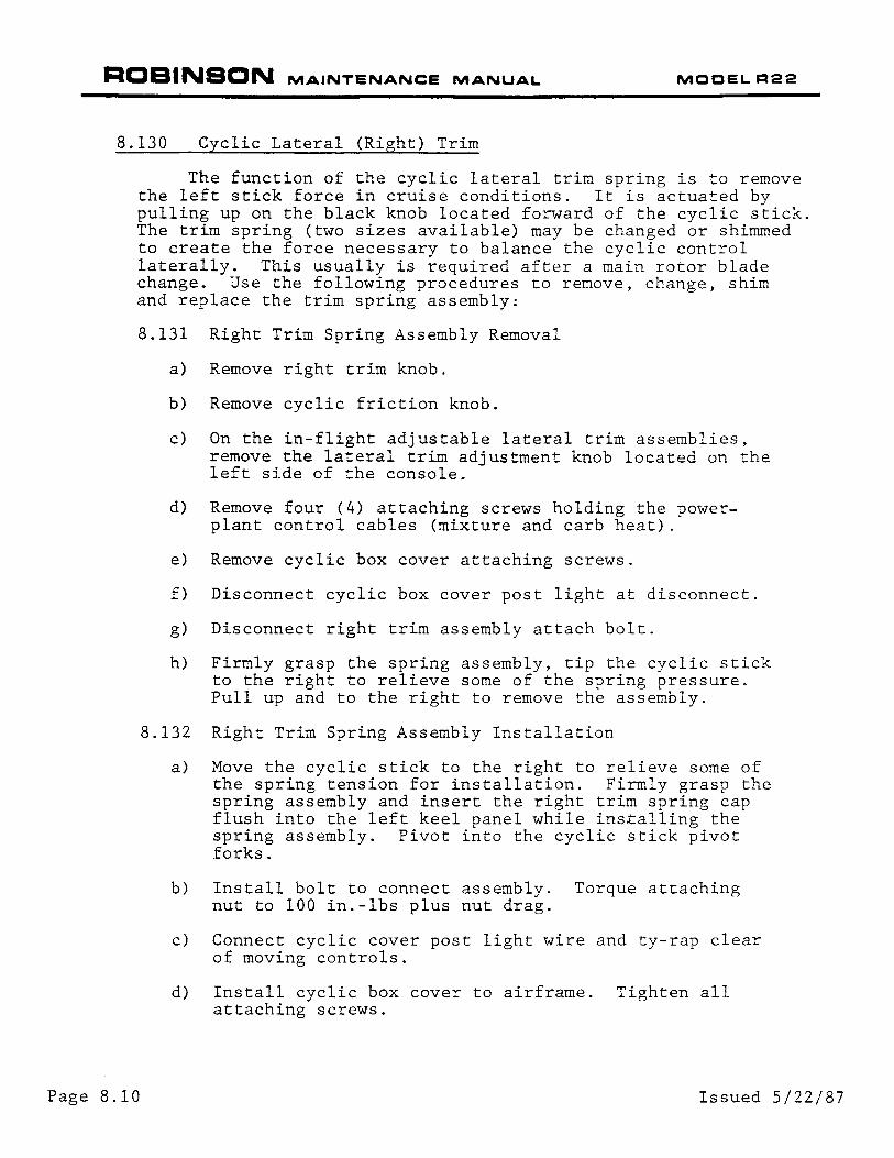
8.130 Cyclic Lateral (Right) Trim
The function of the cyclic lateral trim spring is to remove the left stick force in cruise conditions. It is actuated by pulling up on the black knob located forward of the cyclic stick. The trim spring (two sizes available) may be changed or shimmed to create the force necessary to balance the cyclic control laterally. This usually is required after a main rotor blade change. Use the following procedures to remove, change, shim and replace the trim spring assembly:
8.131 Right Trim Spring Assembly Removal
Page 8.10
a) Remove right trim knob.
b) Remove cyclic friction knob.
c) On the in-flight adjustable lateral trim assemblies, remove the lateral trim adjustment knob located on the left side of the console.
d) Remove four (4) attaching screws holding the powerplant control cables (mixture and carb heat) .
e) Remove cyclic box cover attaching screws.
f) Disconnect cyclic box cover post light at disconnect.
g) Disconnect right trim assembly attach bolt.
h) Firmly grasp the spring assembly, tip the cyclic stick to the right to relieve some of the spring pressure. Pull up and to the right to remove the assembly.
8.132 Right Trim Spring Assembly Installation
a) Move the cyclic stick to the right to relieve some of the spring tension for installation. Firmly grasp the spring assembly and insert the right trim spring cap flush into the left keel panel while ins~alling the spring assembly. Pivot into the cyclic stick pivot forks.
b) Install bolt to connect assembly. Torque attaching nut to 100 in.-lbs plus nut drag.
c) Connect cyclic cover post light wire and ty-rap clear of moving controls.
d) Install cyclic box cover to airframe. Tighten all attaching screws.
Issued 5/22/87

ROBINSON MAINTENANCE MANUAL MODEL R22
8.132 Right Trim Spring Assembly Installation (cont'd)
e) Tighten four attaching screws holding the powerplant control cables (mixture & carb heat).
f) Install right trim knob.
g) Install cyclic friction knob. Install rollpin and safety wire.
h) On the in-flight adjustable lateral trim assemblies, install the adjustment knob on the trim assembly shaft located on the left side of the console.
8.133 Right Trim Spring Replacement & Shimming (See Fig. 8-4)
a) Spring Replacement
1. Remove the right trim assembly per Section 8.131.
2. Remove the cotter pin from the clevis pin.
3. Squeeze the spring and remove the clevis pin.
4. Remove the A581-l arm, A588-l spacer, and A583-1 spring cap.
5. Replace the spring as indicated by flight testing.
NOTE
Changing of the trim spring will create a large change in trim. Shimming of the springs may be required to obtain the desired trim forces.
On the in-flight adjustable lateral trim assemblies, remove the A584-l bearing support and Al30-46 spacer. Remove the A583-2 cap by unscrewing it from the assembly shaft.
6. Reinstall the A581-l spring cap, A588-l spacer, and A583-l arm.
7. Install the clevis pin and cotter pin. On the in-flight adjustable lateral trim assemblies, install the A583-2 cap on the shaft, then the Al30-46 spacer, then the A584-l bearing support.
8. Install the right trim assembly per Section 8.132.
Issued 5/22/87 Page 8.11
ROBINSON MAINTENANCE MANUAL MODEL R22
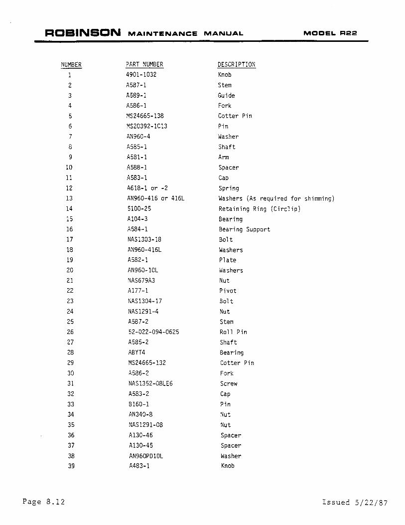
NUMBER PART NUMBER DESCRIPTION
1 4901-1032 Knob
2 A587-1 Stem
3 A589-1 Guide 4 A586-1 Fork
5 MS24665-138 Cotter Pin
6 MS20392-1Cl3 Pin 7 AN960-4 Washer
8 A585-1 Shaft 9 A581-1 Arm
10 A588-1 Spacer
11 A583-1 Cap
12 A618-1 or -2 Spring 13 AN960-416 or 416L Washers (As required for shimming)
14 5100-25 Retaining Ring (Circlip) 15 A104-3 Bearing 16 A584-1 Bearing Support 17 NAS1303-18 Bolt 18 AN960-416L Washers 19 A582-1 Plate 20 AN960-10L Washers 21 NAS679A3 Nut 22 A177-1 Pivot
23 NAS1304-17 Bolt 24 NAS1291-4 Nut 25 A587-2 Stem 26 52-022-094-0625 Roll Pin 27 A 58 5-2 Shaft 28 ABYT4 Bearing 29 MS24665-132 Cotter Pin 30 A586-2 Fork
31 NAS1352-08LE6 Screw 32 A583-2 Cap
33 B160-1 Pin 34 AN340-8 Nut 35 NAS1291-08 Nut
36 A130-46 Spacer 37 Al30-45 Spacer
38 AN960PD10L Washer 39 A483-1 Knob
Page 8.12 Issued 5/22/87
ROBINSON MAINTENANCE MANUAL
-----25
Issued 5/22/87
SHIM AT THIS LOCATION
11
12
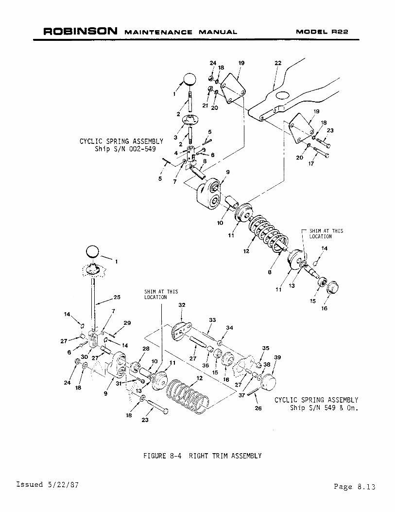
FIGURE 8-4 RIGHT TRIM ASSEMBLY
8
11
MODEL R22
r SHIM AT THIS
\
LOCATION
14 ~ - ) I
J
1s I 16
Page 8.13
I
ROBINSON MAINTENANCE MANUAL MOCELR22
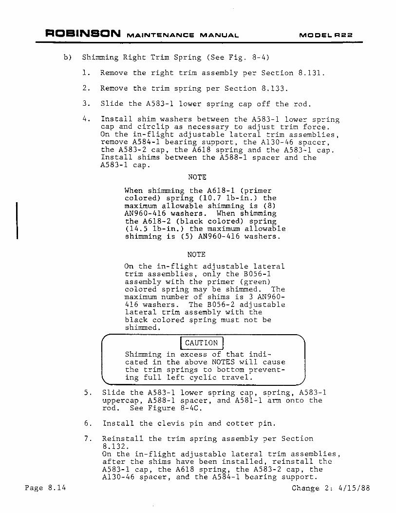
b) Shimming Right Trim Spring (See Fig. 8-4)
Page 8.14
1. Remove the right trim assembly per Section 8.131.
2. Remove the trim spring per Section 8.133.
3. Slide the A583-l lower spring cap off the rod.
4. Install shim washers between the A583-l lower spring cap and circlip as necessary to adjust trim force. On the in-flight adjustable lateral trim assemblies, remove A584-l bearing support, the A130-46 spacer, the A583-2 cap, the A618 spring and the A583-1 cap. Install shims between the A588-1 spacer and the A583-1 cap.
NOTE
When shimming the A618-1 (primer colored) spring (10.7 lb-in.) the maximum allowable shimming is (8) AN960-416 washers. When shimming the A618-2 (black colored) spring (14.5 lb-in.) the maximum allowable shimming is (5) AN960-416 washers.
NOTE
On the in-flight adjustable lateral trim assemblies, only the B056-l assembly with the primer (green) colored spring may be shimmed. The maximum number of shims is 3 AN960-416 washers. The B056-2 adjustable lateral trim assembly with the black colored spring must not be shimmed.
I CAUTION I Shimming in excess of that indicated in the above NOTES will cause the trim springs to bottom preventing full left cyclic travel.
5. Slide the A583-l lower spring cap, spring, A583-1 uppercap, A588-1 spacer, and A581-1 arm onto the rod. See Figure 8-4C.
6. Install the clevis pin and cotter pin.
7. Reinstall the trim spring assembly per Section 8.132. On the in-flight adjustable lateral trim assemblies, after the shims have been installed, reinstall the A583-1 cap, the A618 spring, the A583-2 cap, the Al30-46 spacer, and the A584-1 bearing support.
Change 2: 4/15/88
ROBINSON MAINTENANCE MANUAL MOCELR22
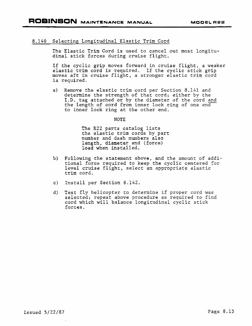
8.140 Selecting Longitudinal Elastic Trim Cord
The Elastic Trim Cord is used to cancel out most longitudinal stick forces during cruise flight.
If the cyclic grip moves forward in cruise flight, a weaker elastic trim cord is required. If the cyclic stick grip moves aft in cruise flight, a stronger elastic trim cord is required.
a) Remove the elastic trim cord per Section 8.141 and determine the strength of that cord; either by the I.D. tag attached or by the diameter of the cord and the length of cord from inner lock ring of one ena-to inner lock ring at the other end.
NOTE
The R22 parts catalog lists the elastic trim cords by part number and dash numbers also length, diameter and (force) load when installed.
b) Following the statement above, and the amount of additional force required to keep the cyclic centered for level cruise flight, select an appropriate elastic trim cord.
c) Install per Section 8.142.
d) Test fly helicopter to determine if proper cord was selected; repeat above procedure as required to find cord which will balance longitudinal cyclic stick forces.
Issued 5/22/87 Page 8.15
ROBINSON MAINTENANCE MANUAL MCCEL R22
This page intentionally left blank.
Page 8.16 Issued 5/22/87
ROBINSON MAINTENANCE MANUAL MOOELR22
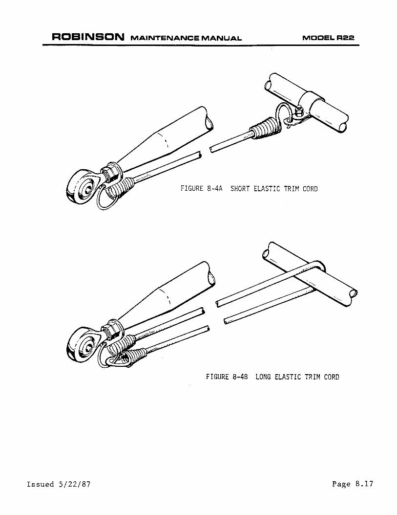
FIGURE 8-4A SHORT ELASTIC TRIM CORD
FIGURE 8-48 LONG ELASTIC TRIM CORD
Issued 5/22/87 Page 8.17
ROBINSON MAINTENANCE MANUAL MODELR22
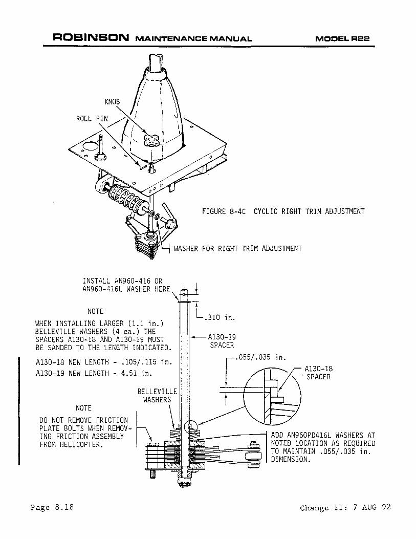
INSTALL AN960-416 OR AN960-416L WASHER HERE
NOTE WHEN INSTALLING LARGER (1.1 in.) BELLEVILLE WASHERS (4 ea.) THE SPACERS A130-18 AND A130-19 MUST BE SANDED TO THE LENGTH INDICATED.
Al30-18 NEW LENGTH- .105/.115 in. A130-19 NEW LENGTH - 4.51 in.
Page 8.18
FIGURE 8-4C CYCLIC RIGHT TRIM ADJUSTMENT
WASHER FOR RIGHT TRIM ADJUSTMENT
\•
-Al30-19 SPACER
Change 11: 7 AUG 92
ROBINSON MAINTENANCE MANUAL MCCELR22
8.141 Longitudinal Trim Cord Removal
NOTE
For inspection criteria of trim cord, See Section 2.410, Item 4.
a) Remove the screws holdin3 the cabin bottom fore-aft inspection panel.
NOTE
If transponder antenna is installed on this inspection panel, slowly lower panel and disconnect the antenna lead and ground wire to the antenna, pull XPDR circuit breaker and tag C.B. with"Antenna Rmvd."
b) Push cyclic stick full forward.
c) If short elastic trim cord installed as shown in Figure 8-4A, unhook trim cord at front tab of Al21-l push-pull tube and at clip mounted to support to remove trim cord.
d) To remove long elastic trim cord installed as shown in Figure 8-4B, disconnect bottom hook and relieve tension on cord to remove the top hook connected to front tab of Al21-l push-pull tube.
8.142 Longitudinal Trim Cord Installation
a) Ensure clamp and clip are installed per Figure 8.4A
b) For short cord installation see Figure 8-4A
c) For long cord installation see Figure 8-4B
d) Check clearances of trim cord hooks to push-pull tube~ wire bundle and comm. wires out of bottom of cyclic stick.
I WARNING I Ensure clearance is maintained between the trim cord hooks and the push-pull tubes and wiring throughout entire cyclic control travel.
e) Connect XPDR antenna lead and ground wire if installed on inspection panel.
f) Install panel and tighten attachment screws.
g) Remove tag and engage circuit breaker.
Change 7: 12 JAN 90 Page 8.19
ROBINSON MAINTENANCE MANUAL MODELR22
8.150 Cyclic Friction Assembly
Page 8.20
Cyclic Friction is located in the front left corner of the cyclic box cover. Turning the knob clockwise applies friction to both the longitudinal and lateral cyclic. If friction cannot be applied by turning knob clockwise, adjustment of friction may be required.
8.151 Cyclic Friction Adjustment
a) Turn friction knob counter-clockwise until it stops.
b) Remove the roll pin.
c) Lift knob off shaft.
d) Install a thick or thin washer (AN960-416 or 416L) as required to give the proper friction at the center of the cyclic grip measured in a lateral direction. See Figure 8-4C.
System friction with right trim off, fore and aft trim cord removed, and CYCLIC FRICTION OFF:
0-5 lb. - Lateral
0-7 lb. - Fore and Aft
CYCLIC FRICTION ON:
7-13 lb. - Lateral
e) Replace knob and install roll pin.
f) Move flight controls throughout complete travel. Verify no binding or clearance problems.
NOTE
If friction assembly will not tighten install larger (1.1 inch) belleville washers (4 ea.) Bll25-078 and change length of spacers per Figure 8-4D.
I CAUTION I New friction knob which has roll pin hole drilled thru knurled section of knob must be used with (1.1 inch) belleville washers.
Change 7: 12 JAN 90
ROBINSON MAINTENANCE MANUAL
8.160 Al21-7 Push Pull (P-P) Tube
8.161 Al21-7 Push-Pull Tube Removal
MOCEL R22
a) Remove belly panel, vertical panel between seat backs and mast fairing, disconnecting pitot line at pitot fitting.
b) Remove vertical firewall maintenance hole plug to remove Al21-7 P-P tubes.
NOTE
IF HOLES NOT PRESENT, INSTALL USING RHC KIT KI-21.
c) Remove NAS1304-44 bolt attaching -7 P-P tube rod ends to cyclic fork.
d) Disconnect bolts holding Al21-7 P-P tubes at swashplate.
e) Tape sheet metal edges to prevent P-P tube removal damage.
f) Position swashplate and rotor to slide Al21-7 P-P tube up and clear. Mark right and left tubes if they are to be reinstalled.
g) Inspect P-P tubes and sleeves for damage.
h) Inspect P-P tube guide for wear. The guide should be replaced if excessively worn or if fretting evident between guide material and riveted aluminum support.
NOTE
If P-P tube replaced, adjust rod ends to obtain same center-to-center length or M.R. Flight Controls will require rigging per R22 Maintenance Manual Section 10.
8.162 Al21-7 Push-Pull Tube Inspection/Repair
1. Nicks, cuts or scratches in the tube which are longitudinal not more than 0.010 inches deep, or across the tube and not more than 0.005 inches deep may be polished out.
2. Dented or flattened tube of more than five percent of its diameter must be replaced.
3. Maximum tube wear at guide 0.015 inch per wall after smoothing wear ridges. Epoxy primer repair surfaces before sleeve installation. Any tube wear requires sleeve installation.
4. Replace tube worn in excess of 0.015 inch after polishing.
Issued 5/22/87 Page 8.21

ROBINSON MAINTENANCE MANUAL
8.163 Sleeve Installation Onto Al21-7 Push-Pull Tube
NOTE
Repair any wear damage on Al21-7 P-P tube per Section 8.162 prior to the P-P tube sleeve installation.
a) Clean P-P tube by lightly using MEK or acetone.
MODEL R22
b) Apply tape to restrict adhesive to 6.5 inch area located 31 inches from end of P-P tube (not end of rod end).
c) Test paint for paint bubbling; apply l-inch band of adhesive to one end of 6.5 inch area. If paint bubbles, remove paint and apply epoxy primer to area before applying adhesive to whole 6.5 inch area.
I WARNING I Adhesive to be applied to complete area under P-.P tube sleeve.
d) Apply adhesive supplied in kit to whole 6.5 inch area. (It will set and become stringy very quickly. Brush thin coat of adhesive without large lumps as rapidly as possible).
NOTE
Sleeve must be installed within two minutes after adhesive applied.
e) Slide sleeve onto tube and center of adhesive.
f) Rotate tube and apply heat using up to 1200-watt heat gun to evenly shrink sleeve producing smooth surface.
I CAUTION I DO NOT APPLY HEAT CONTINUOUSLY TO SAME AREA.
g) Allow to cool and apply adhesive to seal end of sleeve. Do not have adhesive at ends above surface of sleeve or sleeve will be damaged or will not enter guide during installation.
8.164 Push-Pull Tube Sleeve Inspection
a) Visually inspect sl,eeve for wrinkles, pin holes. bubbles, gouges, torn areas. etc. Replace sleeve if any damaged or suspect areas are found.
Page 8.22 Issued 5/22/87

ROBINSON MAINTENANCE MANUAL MCCEL R22
8.165 Al21-7 Push-Pull Tube Installation
a) Inspect P-P tube guide for wear. The guide should be replaced if excessively worn or if fretting evident between guide material and moveable guide plate.
NOTE
Old-style guide bushings which are riveted to fuselage must be replaced with moveable guide kit (RHC Kit KI-19A) if Al21-7 Push-Pull tubes are worn. Reference RHC Service Bulletin :fj36.
b) Loosely (snug) install moveable guide on underside of airframe support A439-l per Figure 8-4E.
I CAUTION I Extreme care must be taken when installing Al21-7 P-P tube into guide to prevent damage to P-P tube sleeve.
c) Install Al21-7 P-P tube, ensure spacers installed properly. Reference Figure 8.4E.Torque attach bolt 100 in.-lb. plus nut drag.
d) Attach Al21-7 P-P tubes to swashplate. Torque attach bolts 100 in.-lb. plus nut drag.
e) Raise collective approximately seven (7) inches (measured from pilot throttle handle to center panel) with cyclic neutral.
f) Tighten guides three attach bolts to slight friction and verify Al21-7 P-P tubes are centered in guide bore. Torque guide attach bolts 40 in.-lb. and torque stripe nuts.
g) Remove protective tape from sheet metal edges used to protect P-P tubes during installation.
h) Check full travel clearances of flight controls.
1) Upper frame forward two boltheads at horizontal firewall to Al21-7 P-P tubes minimum clearance .010 inch.
2) Fuel tank top inboard flange to left Al21-7 P-P tube minimum clearance .10 inch.
Issued 5/22/87 Page 8.23
ROBINSON MAINTENANCE MANUAL MOCELR22
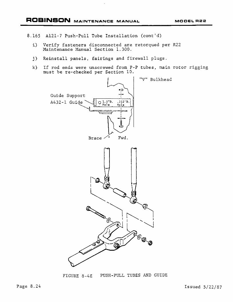
8.165 Al21-7 Push-Pull Tube Installation (cont'd)
i) Verify fasteners disconnected are retorqued per R22 Maintenance Manual Section 1.300.
j) Reinstall panels, fairings and firewall plugs.
k) If rod ends were unscrewed from P-P tubes, main rotor rigging must be re-checked per Section 10.
"V" Bulkhead
Fwd.
FIGURE 8-4E PUSH-PULL TUBES AND GUIDE
Page 8.24 Issued 5/22/87

ROBINSON MAINTENANCE MANUAL MOCELR22
8.200 COLLECTIVE CONTROL
8. 210 Collective Stick Assembly (Standard or Removable)
8.211 Collective Stick Removal
a) Remove vertical center panel, right and left seat backs and collective boot.
b) Remove collective spring guard in aft left baggage compartment.
c) Place collective in full down position. Use either the MT294-1 collective spring tool or Q.032"safety wire to remove the spring assembly. If safety wire is used, twist wire around rod end to rod end several times to assure that the spring assembly can be removed safely.
I WARNING I Spring is under compression and failure to comply with above procedure can cause bodily harm and/ or damage to rotorcraft.
d) Remove bottom spring attach bolt slowly while moving collective slightly to put spring tension onto re-s training safety wire. When belt is removed, swing the spring assembly forward for more clearance during removal.
e) Disconnect collective stop at the A348-l seat belt anchor.
Issued 5/22/87 Page 8.25
ROBINSON MAINTENANCE MANUAL MOCELR22
8.211 Collective Stick Removal (cont'd)
NOTE
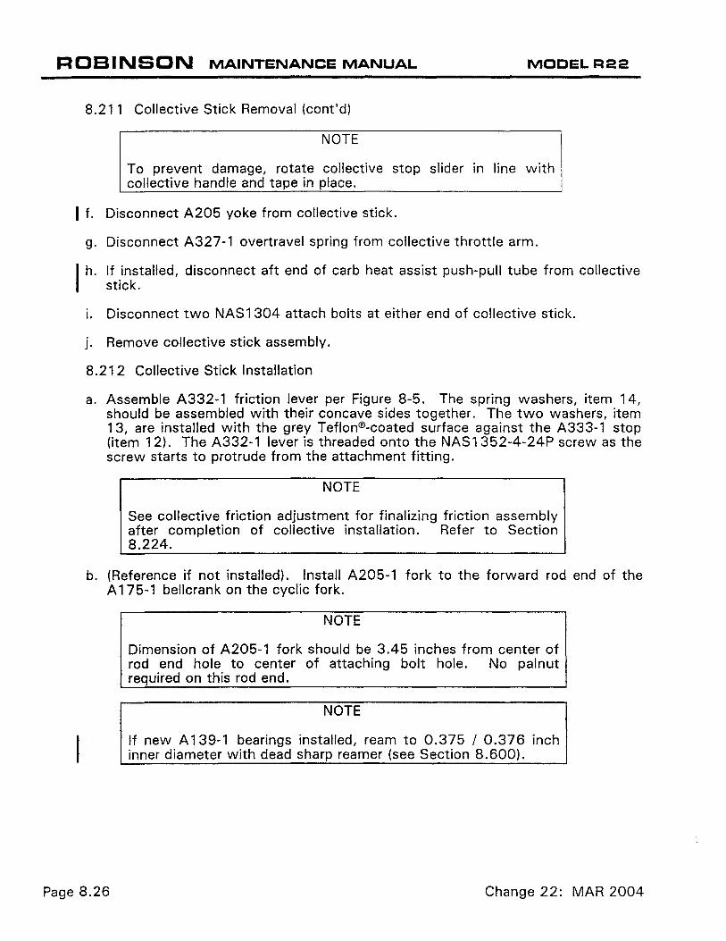
To prevent damage, rotate collective stop slider in line with collective handle and tape in place.
I f. Disconnect A205 yoke from collective stick.
g. Disconnect A327-1 overtravel spring from collective throttle arm.
If installed, disconnect aft end of carb heat assist push-pull tube from collective stick.
i. Disconnect two NAS 1 304 attach bolts at either end of collective stick.
j. Remove collective stick assembly.
8.212 Collective Stick Installation
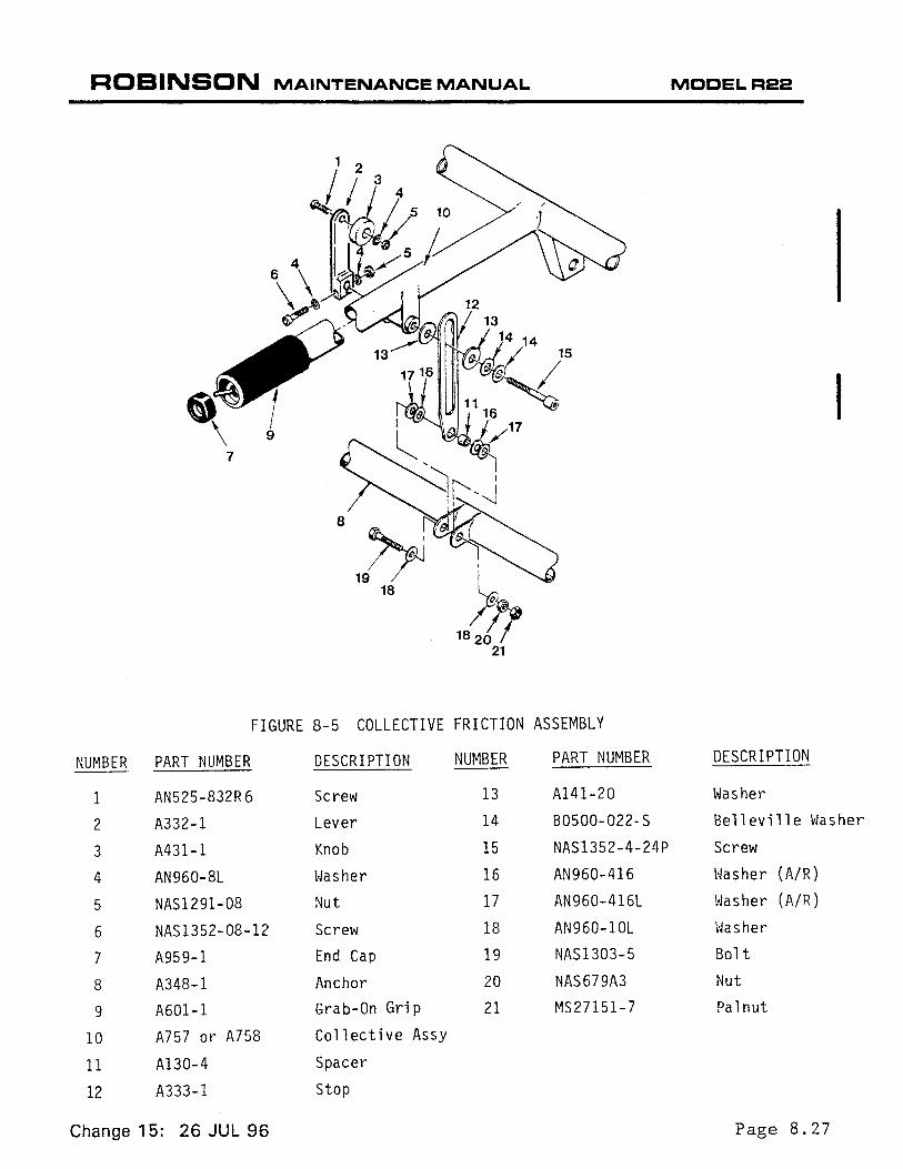
a. Assemble A332-1 friction lever per Figure 8-5. The spring washers, item 14, should be assembled with their concave sides together. The two washers, item 13, are installed with the grey Teflon®-coated surface against the A333-1 stop (item 12). The A332-1 lever is threaded onto the NAS1352-4-24P screw as the screw starts to protrude from the attachment fitting.
NOTE
See collective friction adjustment for finalizing friction assembly after completion of collective installation. Refer to Section 8.224.
b. (Reference if not installed). Install A205-1 fork to the forward rod end of the A 175-1 bellcrank on the cyclic fork.
Page 8.26
NOTE
Dimension of A205-1 fork should be 3.45 inches from center of rod end hole to center of attaching bolt hole. No palnut required on this rod end.
NOTE
If new A 139-1 bearings installed, ream to 0.375 I 0.376 inch inner diameter with dead sharp reamer (see Section 8.600).
Change 22: MAR 2004
ROBINSON MAINTENANCE MANUAL MOCELR22
I
8
19~ 18
FIGURE 8-5 COLLECTIVE FRICTION ASSEMBLY
NUMBER PART NUMBER DESCRIPTION NUMBER PART NUMBER DESCRIPTION
1 AN525-832R6 Screw 13 Al41-20 Washer
2 A332-1 Lever 14 80500-022-S Belleville Washer
3 A431-l Knob 15 NAS1352-4-24P Screw
4 AN960-8L vJasher 16 AN960-416 Hasher (A/R)
5 NAS1291-08 Nut 17 AN960-416L t~asher (A/R)
6 NAS1352-08-12 Screw 18 AN960-10L vJa sher
7 A959-1 End Cap 19 NAS1303-5 Bolt
8 A348-1 Anchor 20 NAS679A3 Nut
9 A601-l Grab-On Grip 21 MS27151-7 Pal nut
10 A757 or A758 Collective Assy
11 A130-4 Spacer
12 A333-1 Stop
Change 15: 26 JUL 96 Page 8.27
ROBINSON MAINTENANCE MANUAL MODELR22
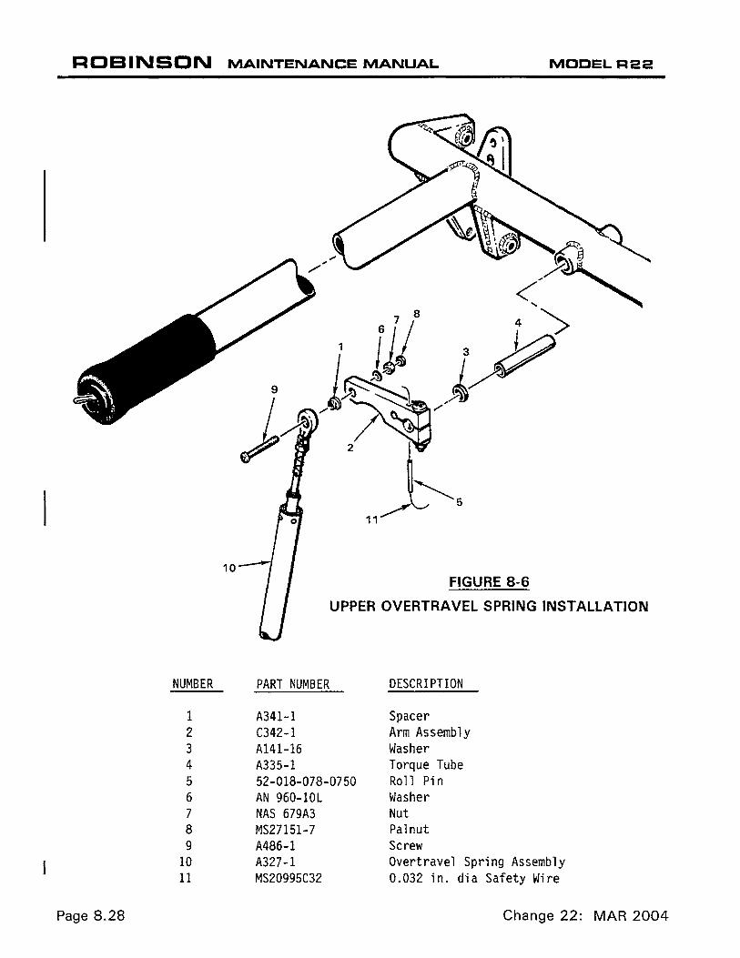
10 FIGURE 8-6
UPPER OVERTRAVEL SPRING INSTALLATION
NUMBER PART NUMBER DESCRIPTION
1 A341-1 Spacer 2 C342-1 Arm Assembly 3 A141-16 Washer 4 A335-1 Torque Tube 5 52-018-078-0750 Roll Pin 6 AN 960-lOL Washer 7 NAS 679A3 Nut 8 MS27151-7 Pal nut 9 A486-1 Screw
10 A327-1 Overtravel Spring Assembly 11 MS20995C32 0.032 in. dia Safety Wire
Page 8.28 Change 22: MAR 2004
ROBINSON MAINTENANCE MANUAL MOCELR22
8.212 Collective Stick Installation (cont'd)
c) Install collective stick into rotorcraft.
d) Connect collective inboard and outboard attach bolts.
NOTE
Special All5-l spacer required against the A329-l bearing block assembly. Smaller end against inner ball; larger end against bolthead.
Torque to 100 in~bs. plus nut drag. Install palriuts. Attach A205-l fork to the collective stick. Torque to 100 in-lb. plus nut drag. Install palnut. Verify smooth operation of fork pivot.
e) Install lower end of A333-l stop to the A348-l seat belt anchor. When installing A333-l stop onto the Al30-4 spacer, add AN960-416 and 416L washers on either side of stop as required to prevent binding and to obtain zero to .031 inch axial play. Torque nut to 27 in.-lb. plus nut drag. Install palnut. Check for binding and axial play.
f) Connect collective spring and install cover per Section 8.
g)
Issued 5/22/87
I WARNING I Failure to remove restraining safety wire after collective spring is installed can limit control travel creating a safety-of-fligh.t hazard.
Install the A327-l overtravel · spring to the end hole of the A342-l collective arm. (See Fig. 8-6).
NOTE
Use special A486-l screw and A341-l spacer. With screw head against rod end, install spacer with large diameter against collective arm. Torque to 28 in.-lb. plus nut drag. Install palnut.
Page 8.29

ROBINSON MAINTENANCE MANUAL MOOELR22
8.212 Collective Stick Installation (cont'd)
WARNING
Improper installation can cause binding, rod end damage or rod end separation with subsequent loss of engine throttle control
If installed, connect aft end of carb heat assist push-pull tube to flat side of collective arm.
i. Adjust throttle correlation rigging per Section 10.150.
j. Install panels and seat backs.
8.220 Collective Spring Assembly (See Figure 8-8)
The collective spring assembly is installed to balance in-flight main rotor collective control forces. A038-1 thru -7 spring assemblies may be adjusted or springs changed to rebalance collective control using the following springs and procedure:
Assembly P /N Spring P/N Spring Color Spring Constant
A038-1 A429-1 (old) Silver 89 lb/in. A038-2 A429-2 (old) Primer 35 lb/in. A038-3 or -5 A429-3 Grey 50 lb/in. (weak) A038-4 A429-4 (old) Black 70 lb/in. A038-6 A429-5 Gold 50 lb/in. (standard) A038-7 A429-8 White 71 lb!in. (strongest)
Adjust A038-1, -2, -3, and -4 spring assemblies per Section 8.223. Adjust A038-5, -6 and -7 spring assemblies per Section 8.224.
NOTE
A038-5 spring assembly replaces A038-2 assembly. A038-6 assembly replaces A038-1, -3, & -4 assemblies.
WARNING
Exercise extreme care when working with compressed collective springs. Always relieve spring compression slowly.
8.221 Collective Spring Removal
a. Remove left seat back. Remove fuel valve handle.
Page 8.30 Change 22: MAR 2004

ROBINSON MAINTENANCE MANUAL MODELR22
UP
h-.---.l.A:...--- - .032" STAINLESS
NUMBER
1 2 3 4 5 6 7 8 9
4.30/4.00"
STEEL SAFETY WIRE
MT294-1 COLLECTIVE SPRING TOOL INSTALLED
FIGURE 8-7 A038-1 THROUGH -4 COLLECTIVE SPRING ASSEMBLY
PART NUMBER DESCRIPTION
A0127-3 Rod End NAS679A3 Nut AN960-10L Washer NAS6603-6 Bolt NAS679A06 Nut AN960-6 Washer AN315-3R Nut A426-3 Plate MS24665-69 Cotter Pin
Change 16: 19 SEP 97
1 A038-1 through -4 ~ \ COLLECTIVE SPRING
2---11::'@'(@ ASSEMBLY
3~~ A038-5, -6, & -7 COLLECTIVE SPRING
7~l0s \ 8~~\\ 4
9"" -~~\ 5 /r ~~6 y ·I
j~-10
@ ASSEMBLY
2/;@_~~3 4 3 /u~
NUI~BER
10 11
12 13 14 15 16 17 18
14 I T.....___ • @ 5
r-r-:5'"6 1r"15 '~~ ---,0
'~ 7 4 ft!n~
\ ;.----18
1\J' 1 '-._\ ~ ---~~'--
FIGURE 8-8 COLLECTIVE SPRING ASSEMBLY
PART NUMBER DESCRIPTION
A428-1 Rod A429-l thru -4 Spring A426-4 Plate AN960-10 Washer B292-3 Rod End A426-5 Cap
· A429-3, -5, or -8 Spring
A426-6 Cap MS27151-7 Pal nut
Page 8.31

ROBINSON MAINTENANCE MANUAL MOCELR22
8.221 Collective Spring Removal (cont'd)
attach screws and fuel valve plate.
b) Remove REMOVE ener. clip. move.
the collective spring cover. Loosen - DO NOT screw located on aft vertical firewall stiffRemove screw at top of cover from nut or nut Slide cover from under loosened screw and re-
c) Place the collective in the full down position. Use either the MT294-1 collective spring tool or .032 in. safety wire to remove the spring assembly. If safety wire is used, twist wire around rod end to rod end several times to assure that the spring assembly can be removed safely.
I WARNING I Spring is under compression and failure to comply with procedures can cause bodily harm and/or damage to rotorcraft.
d) Remove bottom spring attach bolt slowly while moving collective slightly to put spring tension onto restraining wire.
e) Disconnect upper spring assembly attach bolt and remove the spring assembly.
8.222 Collective Spring Installation
NOTE Overall compressed length for installation to be 4.30/4.00 in. between centers of the roq ends. The nut end of the rod guides to be pointing up (See Figure 8-7).
I WARNING I When installing the A038-5 or -6 spring assembly, both rod ends must be bottomed (B292-3 rod end has left-hand thread) . Failure to bottom both rod ends can cause either one to run out of threads during adjustment and can cause bodily harm.
a) Insert collective spring assembly into the collective stick attachment arm. Install bolt and torque to 40 in.-lbs. plus nut drag.
b) Move collective to align rod end into lower mount. Install bolt and torque to 40 in.-lbs. plus nutplate locking drag.
Page 8.32 Change 9: 5 JUL 90
OCT 2018 Chapter 8 Flight Controls Page 8.33
8.222 Collective Spring Installation (continued)
c) On installation of the spring assembly, be sure to cut and remove the restraining safety wire.
d) Check to make sure that the spring coils are not binding with collective stick full down. Adjust spring assembly as required per § 8.223 or 8.224. Install collective cover.
WARNING
Failure to remove the safety wire or allowing the spring coils to bind can limit the control travel creating a safety-of-flight hazard.
e) Install co-pilot seatback. Tighten seatback screws. Tighten four (4) fuel valve plate attach screws.
WARNING
Ensure proper fuel valve handle orientation.
f) Install fuel valve handle. Verify proper orientation using gascolator drain. (See Fuel Flow Check § 12.600.)
8.223 Collective Spring Adjustment for A038-1 thru -4 Assembly
a) Small force adjustments may be made by screwing the lower rod end in or out. Install the MT294-1 collective spring tool. Remove the lower bolt and loosen the adjustment. After reinstallation, ensure that the spring coils do not bottom out with the collective full down. The maximum extension for the bottom rod end is 1.1 inches provided the spring coils do not bottom (See Figure 8-7).
b) Remove the collective spring per § 8.221.
c) Place spring assembly in a soft-jawed vise.
d) Compress the spring slightly and cut the safety wire.
e) Carefully open the vise to relieve the spring tension and remove the spring.
f) Install a spring selected from the table in § 8.220 to obtain the desired trim force.
g) Compress the spring assembly in a vise to a dimension of 4.30/4.00 inch between the rod end center lines. Safety wire with 0.032 inch diameter stainless steel safety wire (see Figure 8-7).
h) Reinstall the collective spring assembly per § 8.222.
Page 8.34 Chapter 8 Flight Controls OCT 2018
8.224 Collective Spring Adjustment for A038-5, -6, or -7 Assembly
Large spring force adjustments are made by changing spring. Small spring force adjustments may be made as follows:
a. Remove collective spring cover.
b. Loosen palnut and jamnut on lower rod end.
c. With collective up, rotate spring by hand to increase or decrease spring force (lower rod end is right-hand thread; upper rod end is left-hand thread). Screwing rod end in decreases collective-up force. Extending rod ends increases collective-up force.
WARNING
Ensure that spring coils are not binding with collective stick full down after making adjustment. Binding spring coils can limit flight control travel.
d. Standard torque jamnut and palnut per § 23-32.
e. Install collective spring cover.
8.225 Collective Friction Adjustment (see Figure 8-5)
To adjust collective friction:
a. Loosen nut (item 5) on friction lever and position lever in locked position.
b. Turn screw (item 15) in threaded collective attachment fitting clockwise to increase friction, counter-clockwise to decrease friction.
c. Adjust locked friction to 12 to 20 pounds measured at collective grip, using a spring scale pulling up from bottom of travel.
WARNING
Collective friction greater than 20 pounds may prevent aircraft from entering autorotation.
d. Tighten nut (item 5) on friction lever.
ROBINSON MAINTENANCE MANUAL MOCELR22
8.230 RPM Governor System
The governor system senses engine RPM and applies corrective input forces to the throttle; when RPM is low, governor increases throttle and vice versa. Throttle inputs are through a friction clutch which can be easily overridden by the pilot. The governor is active from 80% - 115% engine RPM and can be switched on or off by the pilot using the toggle switch on the end of the right seat collective control.
The governor system is designed to assist the pilot in controlling the RPM in the normal operating range. It may not prevent over- or under-speed conditions generated by aggressive flight maneuvers. Within the active range there is a 3%-wide deadband from 102.5% - 105.5% where the governor will not take action provided the rpm is steady.
The governor system consists of the following major components:
1. The 8286-2 governor controller, a solid-state analog-circuit control unit mounted behind the left seat back. The controller senses engine RPM via tachometer points in the engine right magneto (helicopter left side) and provides a corrective signal to the governor assembly.
2. The 824 7-5 governor assembly, attached to the collective stick assembly behind the left seat back. When activated by the governor controller, the governor gearmotor and attached worm gear drives a friction clutch connected to the throttle.
8.231 Governor Controller Removal
1 . Remove left seat back assembly to gain access to controller.
WARNING
No external adjustment of controller is available. If controller fails to operate correctly, remove and return it to RHC.
2. Disconnect electrical connector.
3. Remove four screws securing governor controller to left seat back assembly.
8.232 Governor Controller Installation
1 . Secure governor controller to left seat back assembly.
2. Connect electrical connector.
3. Install seatback panel. If fuel valve handle has a hexagonal mating recess, perform fuel flow check per Section 12.260.
8.233 Governor Assembly Removal
The governor assembly is behind the left seat back assembly, attached to the collective stick.
1. Remove collective stick per Section 8.211.
Change 22: MAR 2004 Page 8.34A
ROBINSON MAINTENANCE MANUAL
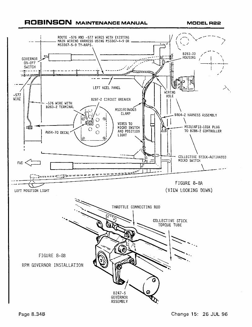
t ROUTE -576 AND -577 WIRES WITH EXISTING --,t= MAIN WIRING HARNESS USING MS3367-4-9 OR MS3367-5-9 TV-RAPS.
GOVERNOR y<=9L __ ___)I ___ _ ON-OFF SWITCH :¢·- ----j
LEFT KEEL PANEL
-577 WIRE B297-2 CIRCUIT BREAKER - -- -576 WIRE WITH
B260-2 TERMINAL ~
(~tt:~; \..: ; II§SJ:r~· ,: () @I
~' N !• I
w-~,._.-A-65-4--7-o-o-Ec_A_L l·o- g .. ®1
L
WIRES TO MICRO SWITCH AND POSITION LIGHT
MODELR22
--/ " / '\ I I \ -+--t-
1 I /
\ ~ B804-2 HARNESS ASSEMBLY
11 ~S3116Fl2-10SX PLUG
TO B286-2 CONTROLLER
\ _;i __ ...:..;,..;,..:_ COLLECTIVE STICK-ACTIVATED
MICRO SWITCH
,! ~- FIGURE 8-8A \S:7 LEFT POSITION LIGHT (VIEW LOOKING DOWN)
FIGURE 8-8B
RPM GOVERNOR INSTALLATION
Page 8.348
8247-5 GOVERNOR ASSEMBLY
Change 15: 26 JUL 96
R 0 BIN SON MAINTENANCE MANUAL MOCELR22
8.233 Governor Assembly Removal (cont'd)
2. Remove three screws securing governor assembly to collective stick.
3. Remove bolt securing governor assembly's output arm to link assembly.
WARNING
No adjustment of friction clutch is permitted. No field replacement of gearmotor is permitted. If friction setting is incorrect, or if gearmotor operates incorrectly, remove governor assembly and return to RHC.
8.234 Governor Assembly Installation
1. Connect governor assembly's output arm to link assembly. Ensure:
a. NAS6603-7 bolt head toward collective grips and no washer under bolt head.
b. AN960-1 0 or NAS620-1 0 washer between governor output arm and rod I end.
c. AN960-1 OL washer between rod end and nut. Torque nut and palnut per Section 1.320.
NOTE
Link assembly length must be 2.47-2.53 inches rod end centerto-center.
2. Ensure governor assembly's output arm points upward towards collective's throttle connecting rod. Attach governor assembly to collective stick. Torque NAS1351-4-28P screw per Section 1.320. Torque both AN503-8-4 screws to 27 in.-lb and safety wire with 0.020 inch diameter safety wire.
3. Rotate throttle grips. Verify smooth operation and no interference.
4. Install collective stick per Section 8.212.
8.239 Governor Troubleshooting
The majority of governor problems are caused by the engine's right (helicopter left side) magneto tachometer contact assembly (points) being out of adjustment or faulty. Refer to TCM Master Service Manual for tachometer contact assembly installation and adjustment.
When operating in the 80%-115% active range, the R22 governor will attempt to maintain engine rpm at 104%±1.5% (102.5%-105.5%). The edges of this governed 3%-rpm wide window, called a "deadband", may be detected as follows:
1. Start engine and run-up helicopter per Pilot's Operating Handbook. Collective must remain fully down during this and following steps.
Change 22: MAR 2004 Page 8.34C

ROBINSON MAINTENANCE MANUAL MOCELR22
,8.239 Governor Troubleshooting (cont'd)
2. Gently hold throttle and very slowly increase rpm (do not exceed 1 07%). Note and record engine rpm indication when governor input (subtle throttle resistance) is encountered.
3. Gently hold throttle and very slowly decrease rpm (do not go below 97%). Note and record engine rpm indication when governor input (subtle throttle resistance) is encountered.
4. Subtract Step 3 indication from Step 2 indication. approximately 3%.
Result should be
A result of 3% but centered beyond 1 04 ± 0. 5% is indicative of a governor controller problem.
Results greater than 3% but still centered on 1 04% are usually indicative of excessive throttle linkage friction or insufficient governor friction.
Check throttle friction by disconnecting overtravel spring assembly upper rod end from C342 arm and attaching a spring scale to the rod end. With carburetor throttle arm in idle position, slowly pull up overtravel spring assembly with spring scale and note maximum 4 pounds moving friction prior to full-open throttle at carburetor. Excessive throttle linkage friction can be caused by binding rod ends, control interference, carburetor throttle shaft bushing elongation, or binding carburetor accelerator pump (typically binds in one direction only).
Check governor friction with collective down, collective friction on, overtravel spring assembly upper rod end disconnected from C342 arm, and C342 arm positioned horizontally. Attach a spring scale to hole in C342 arm and, with scale held tangential to arm, slowly pull on scale and note both the breakaway and the moving frictions. Breakaway friction is typically 0-0.5 pound greater than moving friction. Breakaway friction 1 pound or greater than moving friction may indicate damaged or contaminated governor friction clutch. Moving friction must be minimum 8 pounds until arm stops moving. Insufficient moving friction can be caused by wear, contamination, or loss of spring rate.
Proper governor operation requires a minimum 2:1 ratio of governor friction-tothrottle linkage friction.
Erratic operation is usually indicative of tachometer contact assembly problems or wiring damage. Wiring damage may be evidenced by crushing, pinching, or abrasion, all of which can result in grounding of one or both center wire conductor(s) to the shielding or to structure. Tachometer contact assembly problems may be caused by contamination, oxidation, or loose contact(s), in addition to installation or assembly errors.
Contamination can be caused by over-lubrication of cam follower felt, engine oil leaking past oil seal, or moisture intrusion thru vent plug. Oxidation can be caused by an obstructed vent plug or by engine oil leaking past the oil seal.
When flying in turbulence, or if the engine is lightly "loaded" (drive train almost freewheeling), a fluctuating MAP indication is expected.
Any loose connection in throttle linkage (including worn carburetor throttle shaft bushings) will result in both RPM & MAP oscillations.
Page 8.340 Change 22: MAR 2004

ROBINSON MAINTENANCE MANUAL MOOEL R22
8.300 JACKSHAFT AND SUPPORT STRUTS
8.310 Jackshaft (See Figure 8-9)
8.311 Jackshaft Removal
NOTE
Rigging check should not be necessary if jackshaft support strut rod ends or push-pull tube rod ends are not loosened or removed.
a) Disconnect the push-pull tubes from the jackshaft.
b) Disconnect the two (2) jackshaft support bolts at the upper support strut rod ends.
c) Remove jackshaft.
8.312 Jackshaft Installation
Install jackshaft to strut rod ends. Aft support rod end requires a safety washer A214-3 between the rod end and bolthead. Both upper strut attach boltheads point aft. Torque nut to 100 in.-lbs plus nut drag. Install palnut.
Connect the Al21-3 and -5 push-pull tubes to jackshaft. Both push-pull tube attach boltheads point forward. The forward Al21-3 push-pull tube rod end requires a safety washer A214-3 and All5 spacer between the rod end and bolthead. Torque nuts to 100 in.-lbs plus nut drag. Install palnut.
Verify no binding or interference with control movement throughout flight control travel.
8.320 Strut Assembly (Jackshaft Support)
8.321 Jackshaft Strut Removal
Issued 5/22/87
a) Remove jackshaft per Section 8.311
b) Remove the aft support strut. Disconnect horizontal strut assembly at the 'V' bulkhead. Disconnect the lower strut rod end at the aft main rotor gearbox fitting.
Page 8.35

ROBINS'ON MAINTENANCE MANUAL MOCEL R22
NUf~BER PART NUMBER DESCRIPTION
1 NAS1304-23 Bolt 2 A214-3 Washer 3 A343-1 Strut 4 AN960-416L Washer 5 NAS679A4 Nut 6 MS27151-13 Pal nut 7 A121-5 Push-Pull Tube 8 NAS1304-7 Bolt 9 NAS1304-21 Bolt
10 A121-3 Push-Pull Tube 11 All 5-1 Spacer 12 A337-1 Jack shaft 13 A347-1 Brace 14 NAS1304-2 Bolt 15 AN960-416 Washer 16 AN525-832R6 Screw 17 AN960-8L Washer 18 A437-2 Tab 19 NAS679A08 Nut
Page 8.36 Issued 5/22/87

ROBINSON MAINTENANCE MANUAL
' ' I
10
......___12
8
MODEL R22
A347-5 SHIP S/N 0436 and higher
I
4
FORWARD
FIGURE 8-9 JACK SHAFT INSTAllATION
Corrected Change 25: JUN 2006 Page 8.37
ROBINSON MAINTENANCE MANUAL MODEL R22
8.38
8.321 Jackshaft Strut Removal (cont'd)
NOTE
For ease of installation later, DO NOT disassemble the long horizontal strut from the vertical strut.
c. Forward support strut removal: To remove, it will be necessary to disconnect upper rod end installed through a fuselage tab, DO NOT remove lower rod end from support if possible.
NOTE
For ease of installation later, measure length of strut from center of rod ends and tag strut with length for later reference.
8.322 Jackshaft Strut Installation
NOTE
Two (2) AN960-516L washers are installed on forward supports; one between upper forward rod end jamnut and fuselage tab, other between upper aft jamnut and A34 7 horizontal strut.
1. Install forward support strut.
a. Connect forward vertical support strut lower rod end to forward-right gearbox fitting. Verify minimum preload between bulkhead-mounted jackshaft brace tab and top of strut; adjust strut height as required. Verify proper rod end engagement via strut witness hole.
b. Install strut upper rod end , with palnut and jam nut installed, thru brace tab into top of strut. Adjust rod end center-to-center dimension to previously recorded measurement, if applicable. Verify proper rod end engagement via strut witness hole.
2. Connect aft-vertical strut lower rod end to aft-right main rotor gearbox fitting. Connect vertical diagonal strut to aft-left gearbox fitting, or connect horizontal diagonal strut to Vee-bulkhead, as applicable.
3. Torque bolts per Section 1 .320. Install palnuts, and torque per Section 1.320. Torque stripe per Figure 2-1.
4. Install jackshaft and push-pull tubes per Section 8.312.
5. If aft-vertical strut was disassembled or length changed, adjust aft strut and/ or forward strut to achieve jackshaft level to helicopter keel panel within ± 0.5°. Verify proper rod end engagement through witness hole in strut.
6. Verify proper rod end centering and all bolts, jamnuts, and palnuts are torqued per Section 1 .320 and torque striped per Figure 2-1.
Change 25: JUN 2006
OCT 2018 Chapter 8 Flight Controls Page 8.39
8.400 Swashplate and Main Rotor Pitch Links
8.410 Swashplate
8.411 Swashplate Removal
NOTE
Rigging check is not required if push-pull tube rod end bearing center-to-center dimension has not changed.
1. Remove main rotor hub and blade assembly per §§ 26-20 and 26-10.
2. Disconnect and remove A203 yoke halves.
3. Remove droop stops and elastic teeter stops.
4. Remove swashplate boot.
5. Disconnect three push-pull tubes and rod end of lower A205 fork assembly from lower, non-rotating swashplate.
6. Lift swashplate off slider tube.

Page 8.40 Chapter 8 Flight Controls OCT 2018
8.412 Swashplate Installation
CAUTION
Swashplate plastic balls are obsolete and must be replaced.
1. Verify swashplate rotates freely.
2. On swashplate ear opposite interrupter, attach pitch link’s lower rod end with five AN970-4 washers and two AN960-416L washers under bolt head, one A115-1 spacer on each side of rod end, with the small washers between spacer and large washers. Install additional AN960-416L washer on bolt inboard of inner A115-1 spacer and insert bolt into swashplate ear. Washer stack-up must be located on outside of ear. Install washers under nut as required to expose two to four threads after torquing. Standard torque nut per § 23-32. Install palnut, standard torque per § 23-32, and torque stripe per Figure 2-1.
3. On interrupter-side swashplate ear, attach pitch link with an A214-3 washer under bolthead, one A115-1 spacer on each side of pitch link rod end, and one AN960-416L washer between A115-1 spacer and swashplate ear.
4. On interrupter-side swashplate ear, install A115-1 spacer on protruding length of bolt, then A205 fork assembly rod end (rod end shank pointing up), another A115-1 spacer, one A214-3 washer, and the nut. Standard torque nut per § 23-32. Install palnut, standard torque per § 23-32, and torque stripe per Figure 2-1.
5. Attach A204 arm to A205 fork installed in previous step. If fork has plastic A139-1 bearings, line ream and spot face bearings for correct fit per § 8.600. If fork has C648-2 bearings (dark-brown colored face & bore), install a combination of A117-45, -46, and/or -47 shims between A105-17 journal and A141-43 washer on nut side to provide 0.010/0.001 inch axial play in joint. Refer to Figure 2-8. Verify 2.5 in.-lb maximum pivot friction.
6. Install swashplate and attached pitch links, fork, and arm onto slider tube assembly atop main rotor gearbox.
7. Slide boot over A251 main rotor shaft and set in place.
8. Install A203 yoke assembly onto A251 shaft using A210-1 key to position yoke on shaft. Radiused edge of A210-1 key goes into flange slot in A251 shaft. Standard torque nut per § 23-32. Install palnut, standard torque per § 23-32, and torque stripe per Figure 2-1.
CAUTION
Tighten and torque bolt through A210-1 key first.
8.412 Swashplate Installation (continued)
9. Install opposite clamping bolt in chord-arm side of yoke. As applicable, special torque NAS1305 or NAS6605 bolt per § 23-33, or standard torque NAS1304 or NAS6604 bolt per § 23-32. Install palnut, standard torque per § 23-32, and torque stripe per Figure 2-1.
NOTE
A small space between chord-arm side yoke halves adjacent to driveshaft is normal. Do not exceed bolt torque limits.
10. Connect A204-1 arm to A203 yoke assembly. If yoke has plastic A139-1 bearings, line ream and spot face bearings for correct fit per § 8.600. If yoke has C648-2 bearings (dark-brown colored face & bore), install a combination of A117-45, -46, and/or -47 shims between A105-17 journal and A141-43 washer on nut side to provide 0.010/0.001 inch axial play in joint. Refer to Figure 2-8. Verify 2.5 in.-lb maximum pivot friction.
11. Install A255 counterweights and AN970-4 washers on A203 yoke arm as required for balance.
12. Attach lower A205 fork’s rod end to left side of middle of three lugs grouped together on lower swashplate. Connect forward push-pull tube rod ends to left side of remaining two forward lugs. Aft push-pull tube rod end attaches to right side of lower swashplate aft lug. A214-3 safety washer required between bolthead and A115-1 spacer. A115-1 spacers are required on each side of all rod end balls. Standard torque bolts per § 23-32. Install palnuts, standard torque per § 23-32, and torque stripe per Figure 2-1.
13. Position boot on upper swashplate and ty-rap in place. Ensure upper portion of boot clamps on shaft between upper flange and A203 yoke halves.
14. Temporarily install teeter hinge bolt and journals. Install droop stops and elastic teeter stops. Ensure teeter stop brackets are oriented per Figure 26-5. Standard torque bolts per § 23-32. Install palnut, standard torque per § 23-32, and torque stripe per Figure 2-1. Remove teeter hinge bolt and journals.
15. Verify no binding or interference with control movement throughout flight control travel.
16. Install main rotor hub and blades per §§ 26-20 and 26-10.
17. Track and balance main rotor per § 10.200.
8.413 Reserved
8.414 Reserved
8.415 Reserved
OCT 2018 Chapter 8 Flight Controls Page 8.41
Intentionally Blank
Page 8.42 Chapter 8 Flight Controls OCT 2018

Intentionally Blank
OCT 2018 Chapter 8 Flight Controls Page 8.43

Intentionally Blank
Page 8.44 Chapter 8 Flight Controls OCT 2018

Intentionally Blank
OCT 2018 Chapter 8 Flight Controls Page 8.45

Intentionally Blank
Page 8.46 Chapter 8 Flight Controls OCT 2018

ROBINSON MAINTENANCE MANUAL MOCELR22
This page intentionally left blank. I
Change 16: 19 SEP 97 Page 8.47

I
ROBINSON MAINTENANCE MANUAL MODELR22
8.416 Shimming Upper (Unflanged) Spherical Sleeve with Aluminum Ball
Measure space between top of upper spherical sleeve to top surface of lower swashplate. Determine required A209 spacer thickness by installing a spacer that will completely fill the space. (A209 spacers are available in increments of 0.005 inch.)
a) Install shield plate. Torque screws to 17 in-lbs.
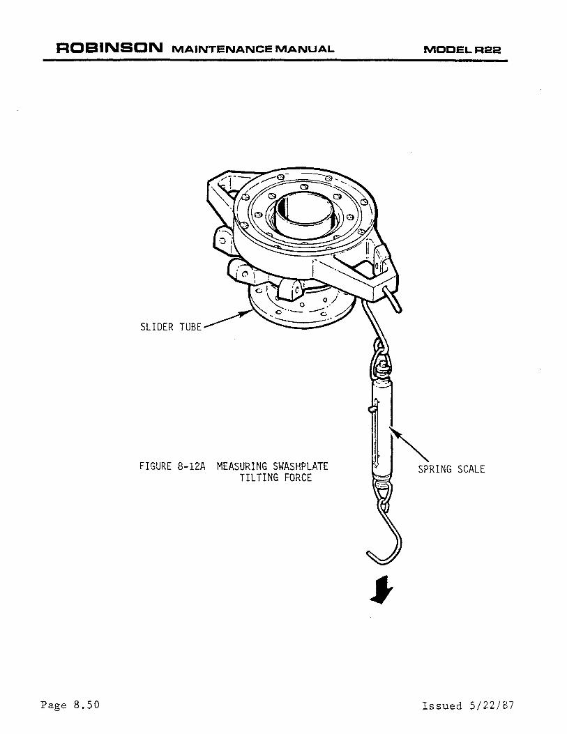
b) Use a spring scale (MT359-1 or equivalent) to pull down at bolt hole in upper swashplate arm as shown in Figure 8-12A. The force required to tilt the swashplate must be free-without-looseness to five pounds maximum, measured while moving; do not use breakaway reading.
c) Use a thicker or thinner A209 spacer to adjust swashplate tilting force. Increase spacer thickness to increase force required to tilt swashplate.
8.500 TAIL ROTOR CONTROLS
8.510 Tail Rotor Pedals (Standard or Removable)
8.511 Tail Rotor Pedal Removal
a) Remove the landing light cover, belly cover and cabin cover between the seats (horizontal).
Page 8.48 Change 15: 26 JUL 96

ROBINSON MAINTENANCE MANUAL MODELR22
A209 SPACER
SPHERICAL SLEEVE (LOWER)
SAFETY WIRE
SCREW--J WASHER--.~
GUARD
I I
Change 22: MAR 2004
SWASHPLATE INNER SCREWS
SWASHPLATE OUTER SCREWS
UPPER SWASHPLATE
A209 SPACER
SPHERICAL SLEEVE (UPPER)
SWASHPLATE CUTAWAY A209 SPACER (SHIM}
UNFLANGED SLEEVE
SAFETY WIRE
I ~SCREW
WASHER
WOODEN BLOCKS
FIGURE 8-12
SWASHPLATE SHIMMING WITH A209 SPACER
Page 8.49
ROBINSON MAINTENANCE MANUAL
Page 8. 50
FIGURE 8-12A MEASURING SWASHPLATE TILTING FORCE
MODELR22
'~ SPRING SCALE
Issued 5/22/87
ROBINSON MAINTENANCE MANUAL MOOEL R22
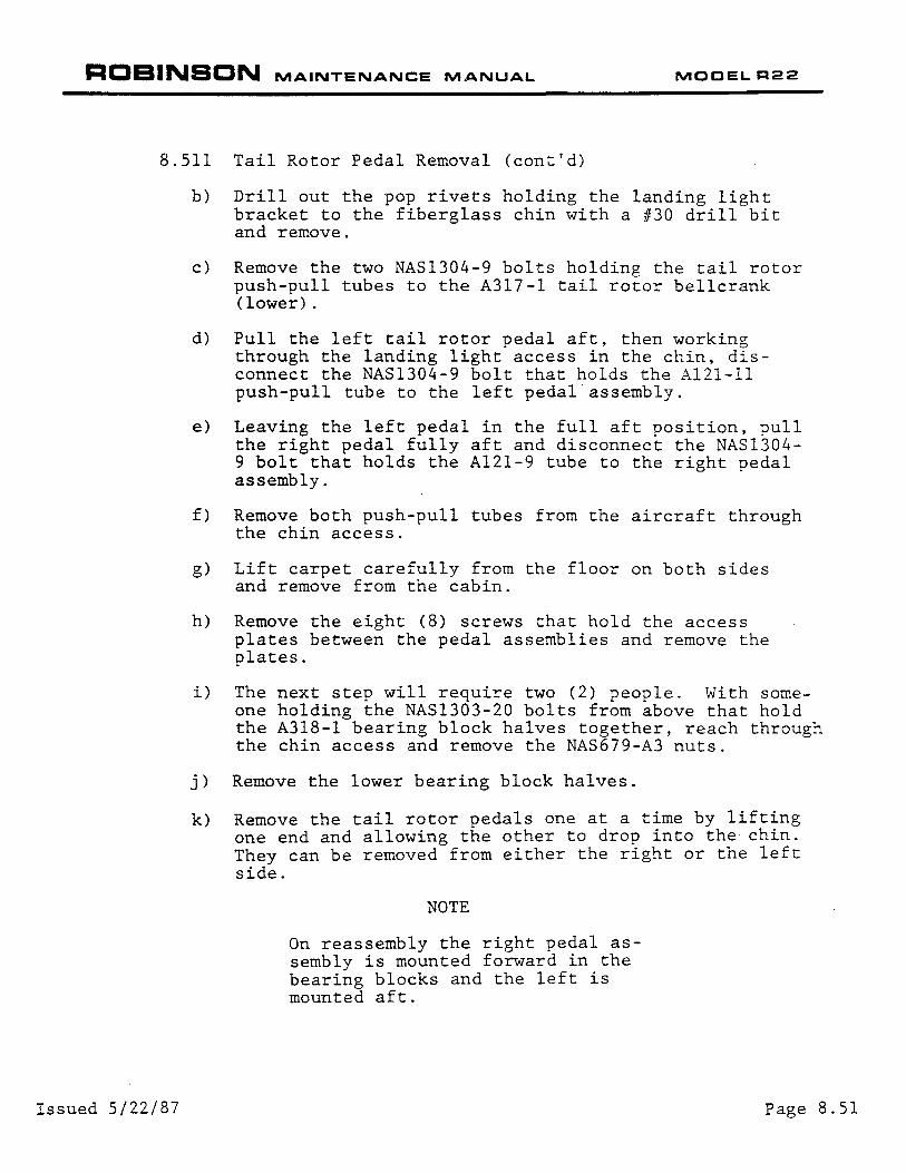
8.511 Tail Rotor Pedal Removal (cont'd)
Issued 5/22/87
b) Drill out the pop rivets holding the landing light bracket to the fiberglass chin with a #30 drill bit and remove.
c) Remove the two NAS1304-9 bolts holding the tail rotor push-pull tubes to the A317-l tail rotor bellcrank (lower).
d) Pull the left tail rotor pedal aft, then working through the landing light access in the chin, disconnect the NAS1304-9 bolt that holds the Al21-ll push-pull tube to the left pedal assembly.
e) Leaving the left pedal in the full aft position, pull the right pedal fully aft and disconnect the NAS1304-9 bolt that holds the Al21-9 tube to the right pedal assembly.
f) Remove both push-pull tubes from the aircraft through the chin access.
g) Lift carpet carefully from the floor on both sides and remove from the cabin.
h) Remove the eight (8) screws that hold the access plates between the pedal assemblies and remove the plates.
i) The next step will require two (2) people. With someone holding the NAS1303-20 bolts from above that hold the A318-1 bearing block halves together, reach through the chin access and remove the NAS679-A3 nuts.
j) Remove the lower bearing block halves.
k) Remove the tail rotor pedals one at a time by lifting one end and allowing the other to drop into the chin. They can be removed from either the right or the left side.
NOTE
On reassembly the right pedal assembly is mounted forward in the bearing blocks and the left is mounted aft.
Page 8.51
ROBINSON MAINTENANCE MANUAL
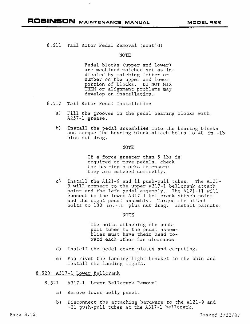
8.511 Tail Rotor Pedal Removal (cont'd)
NOTE
Pedal blocks (upper and lower) are machined matched set as indicated by matching letter or number on the upper and lower portion of blocks. DO NOT MIX THEM or alignment problems may develop on installation.
8.512 Tail Rotor Pedal Installation
MOOELR22
a) Fill the grooves in the pedal bearing blocks with A257-l grease.
b) Install the pedal assemblies into the bearing blocks and torque the bearing block attach bolts to 40 in.-lb plus nut drag.
NOTE
If a force greater than 5 lbs is required to move pedals, check the bearing blocks to ensure they are matched correctly.
c) Install the Al21-9 and 11 push-pull tubes. The Al21-9 will connect to the upper A317-l bellcrank attach point and the left pedal assembly. The A121-11 will connect to the lower A317-1 bellcrank attach point and the right pedal assembly. Torque the attach bolts to 100 in.-lb plus nut drag. Install palnuts.
NOTE
The bolts attaching the pushpull tubes to the pedal assemblies must have their head toward each other for clearance.
d) Install the pedal cover plates and carpeting.
e) Pop rivet the landing light bracket to the chin and install the landing lights.
8.520 A317-1 Lower Bellcrank
8.521 A317-l Lower Bellcrank Removal
a) Remove lower belly panel.
b) Disconnect the attaching hardware to the Al21-9 and -11 push-pull tubes at the A317-l bellcrank.
Page 8.52 Issued 5/22/87
ROBINSON MAINTENANCE MANUAL MOCEL R22
8.521 A317-1 Lower Bellcrank Removal (cont'd)
c) Disconnect the A315 support holding the A317 bellcrank by removing the 4 attach bolts and swing assembly forward.
d) Remove bolt attaching A317 be1lcrank to the A315 support.
8.522 A317-1 Lower Bellcrank Installation
This procedure also covers rigging of the lower pushpull tubes and pedal assemblies. If re-checking of rigging is not required, disregard rigging portions and follow installation sequences.
Issued 5/22/87
a) Install A130-12 spacers and two A105-3 journals inside A316 bellcrank, A141-3 washers are installed against the Al05-3 journals upon assembly to the A315 support outside of aircraft. Excess gap between A315 support attaching flanges and the Al41-3 washers next to the assembled bellcrank may be filled with either A214-3 or Al41-3 washers.
NOTE
When A317 bellcrank is installed, the 3/16"dia. rigging pin hole will be above the pivot point and the bellcrank itself will be aft of the bellcrank support.
Tighten pivot nut ahd check for smooth and free operation. Maximum spring scale drag of 2 lb is acceptable to move the bellcrank. Torque to 100 in-lb plus drag torque if acceptable.
If a force in excess of 2 lbs. is required to move the bellcrank, see Section 8.600 for A139-1 bearing reaming and spotface procedure.
b) Temporarily attach the A315-l and A317-l into aircraft to check for proper push-pull tube rigging length. Insert rigging pin thru the cabin assembly into the A317-l bellcrank for rigging. Temporarily attach Al21-9, 11 and 13 push-pull tubes to the A317.
Place the left and right pedals together at the mid (neutral) travel position. Place a 2.90 inch spacer between each inside pedal and stop. Adjust the rod ends on the Al21-9 and Al21-11 push-pull tubes as required to insert a bolt through the rod end and the A317-1 bellcrank. Check push-pull tube rod end and the A317-l bellcrank. Check push-pull tube rod end witness holes for engagement.
Page 8.53
ROBINSON MAINTENANCE MANUAL MOOEL R22
8.522 A317-l Lower Bellcrank Installation (cont'd)
c) After adjusting pedal travel, remove the rigging pin and apply full left pedal and adjust Al21-13 pushpull tube to obtain .06" minimum clearance of the A013-3 bellcrank and the vertical firewall. Adjust push-pull tube as required.
NOTE
It is permissible for the bellcrank arm to touch and deflect acoustical foam, as long as it does not interfere with free movement and full travel of the controls.
d) With the A315 support and A317 bellcrank attachment, disconnected from the keel panels (A121-9 and -11 push-pull tubes disconnected) slide bellcrank forward.
NOTE
The A121-13 push-pull tube attach bolt must be installed with bolthead to the right side for clearance in vertical tunnel.
NOTE
On installation to the A317 bellcrank, an AN960-416 washer is installed to fill gap between rod end and the left plate of the A317 bellcrank (washer on left side of rod end).
e) Attach A315 bellcrank support to keel panels.
f) Attach the Al21-9 and -11 push-pull tubes to the A317 bellcrank.
g) Torque all attaching NAS1304 bolts to 100 in.-lb plus nut drag. Install palnuts and torque stripe fasteners.
h) Check for smoothness and ease of operation. Move pedals full travel. Check for any interference between tubes, wires and structures.
Page 8.54 Issued 5/22/87
ROBINSON MAINTENANCE MANUAL MOOELR22
8.522 C317-2 Lower Forward Bell Crank Installation (cont'd)
i) If required, check complete Tail Rotor rigging if changes to A 121-9, -11, or -13 push-pull lengths have been made.
j) Verify all attach bolts and jamnuts torqued per Fastener Torques Section 1 .300.
k) Install panels.
8.530 A013-3 Upper Bellcrank
8.531 Bellcrank Removal
1. Remove A 121-15 push-pull tube.
2. Remove belly inspection panel.
3. Disconnect A 121-9 and -11 at A317 bellcrank.
4. Disconnect A315 and A317 bellcrank with A317 bellcrank attached.
5. Slide A315 and A317 bellcranks with A 121-13 push-pull tube attached up to disconnect -13 push-pull tube at upper bellcrank.
NOTE
Upper bellcrank needs to be rotated as far aft as possible to remove A 121-13 push-pull tube attach bolt.
6. Remove upper bellcrank attach bolt. Catch all A214-2 and A 141-3 washers installed as bolt is remove.
7. Remove upper bellcrank from structure.
8.532 Bellcrank Installation
1. Install A 130-12 spacer and two A 105-3 journals inside A013-3 bellcrank. Ream A 139 bearing with 0.375/0.376 inch dead sharp reamer if required for journal's smooth installation.
2. Install bellcrank with A141-3 washers bellcrank with A141-3 washers next to blue Turcite A139-1 bearings. If gap exists between A141-3 washers and outboard support, fill either with A214-3 or A 141-3 washers.
3. Torque attach bolt per Section 1 .320. Install palnut.
Change 23: JAN 2005 Page 8.55
ROBINSON MAINTENANCE MANUAL MOOELR22
8.532 A013-3 Upper Bell crank Installation (cont' d)
4. Check for smoothness and ease of operation.
5. Attach A 121-9, -11 and -13 push-pull tubes along with A31 5 and A317 bellcrank assemblies, following procedure in Section 8.522.
CAUTION
A 1 21-1 3 push-pull tube to AO 1 3-3 upper bellcrank attach bolt head must point to right side of helicopter for clearance.
6. Install the A 121-15 push-pull tube.
7. Check rigging if necessary.
8. Torque all attaching bolts and jamnuts per Section 1 .300.
9. Check for smoothness and ease of operation. Move pedal full travel, check for any interference between tubes, wires and structures.
1 O.lnstall panels.
8.540 A331-1 Intermediate Bellcrank
8.541 A331-1 Intermediate Bellcrank Removal
1 . Disconnect A 1 21-1 5 and -1 7 push-pull tubes from A331-1 bellcrank.
2. Disconnect A331-1 attach bolt and remove bellcrank.
8.542 A331-1 Intermediate Bellcrank Installation
Install two A 1 05-3 journals into bellcrank bearings. An A 141-3 washer is required on each side of bellcrank to A 139-1 bearings. (Ream A 139-1 bearing with 0.375/0.376 inch dead sharp ream if required for journal's smooth installation).
Page 8.56
NOTE
If required for A 1 21-1 7 attach bolt clearance with the scroll two AN960-416 washers may be installed between the bell crank and the frame to raise the bellcrank. This will require use of NAS 1304-40 bolt, to attach bellcrank to frame.
Change 23: JAN 2005
ROBINSON MAINTENANCE MANUAL MOCEL R22
8.542 A331-1 Intermediate Be1lcrank Installation (cont'd)
8.550
a) Torque to 100 in-lb plus nut drag. Install palnuts.
b) Check for smoothness and ease of operation.
c) Connect A121-15 and -17 push-pull tubes. A214-3 safety washers are required under the boltheads.
d) Re-rig if push-pull tube lengths were altered.
e) Move pedals full travel, check for any interference between tubes, wires, components or structures.
Al20-1 Aft Bellcrank
8.551 A120-1 Aft Bellcrank Removal
a)
b)
c)
8.552
Disconnect A121-17 push-pull tube from A120 aft bellcrank.
Disconnect bellcrank pivot from attach bolt connected to tail rotor gearbox:
Remove nut holding bellcrank to the pitch control. Remove bellcrank and reinstall nut and shims found between bellcrank and pitch control for bellcrank installation.
A120-1 Aft Bellcrank Installation
See A031 Pitch Control Installation (See Section 8.562).
8.560
8.561
a)
b)
c)
8.562
a)
b)
Issued 5/22/87
A031 Pitch Control
Pitch Control Removal
Remove tail rotor hub and blade assembly. Mark corresponding tail rotor blade grips, tail rotor pitch change to each of the pitch control ears, for later reinstallation so re-rigging is not required.
Disconnect and remove aft bellcrank per Section 8.551.
Remove pitch control from tail rotor output shaft.
Pitch Control Installation
Slide A031-1 pitch control assembly onto output shaft.
Position A120-1 bellcrank assembly on the tail rotor gearbox and install NAS1304-25 bolt, one AN960-416 washer under bolt head, two MS20002-4 washers, one one each side of the bearing and NAS679-A4 nut.
Page 8.57
ROBINSON MAINTENANCE MANUAL MOOEL R22
Page 8.58
8.562 Pitch Control Installation (cont'd)
b) Measure the gap existing between the A120-l bellcrank ear and the flats on the A125-1 pitch control stud. Install sufficient A117-20, -21 and -22 washers between bellcrank and stud to completely fill the gap but not apply any axial preload on the spherical bearing after all the nuts are tightened. The clearance tolerance is plus or minus .003". Install one AN960-416L washer and NAS679-A4 nut on protruding end of stud. Torque nut to 70 in.-lbs plus nut drag while holding stud from rotating. Install palnut.
c) Torque nut on A120-l bellcrank pivot to 100 in.-lbs plus nut drag. Install palnut.
d) Attach aft end of Al21-17 push-pull tube to the Al20 -1 bellcrank and A214-3 safety washer under nut next to rod end. Torque nut to lOOin.-lb. plus nut drag. Install palnut.
e) Install pitch control links per Section 8.572.
f) Install tail rotor hub and blade assembly (See Section 9.212).
g) Ensure all bolts, jamnut and palnuts torques per Fastener torques, Section 1.300.
8.570 Tail Rotor Pitch Links
8.571 Tail Rotor Pitch Link Removal
NOTE
To ensure proper rigging upon reinstallation of pitch links, mark pitch links to corresponding blade grip and pitch control ear.
a) Disconnect the two attach bolts on either rod end of the pitch link.
b) Remove pitch link.
8.572 Tail Rotor Pitch Link Installation
l WARNING I A214-3 safety washers are to be installed next to rod end.
Issued 5/22/87
ROBINSON MAINTENANCE MANUAL MODEL R22
8.572 Tail Rotor Pitch Link Installation (cont'd)
WARNING
Both pitch links must be same part number (same type and material). Mixing one-piece with adjustable-length pitch links is prohibited. Mixing steel one-piece with aluminum one-piece pitch links is prohibited.
Refer to Figure 9-11 .
1. If installing one-piece pitch link(s); connect pitch link to pitch link control arm and blade pitch horn.
2. If installing new, adjustable-length pitch link(s) based on old pitch link length:
a. Match pitch link to proper blade pitch horn and pitch control arm and connect pitch link. Torque attach bolts per Section 1 .320. Install palnuts, torque per Section 1 .320, and torque stripe per Figure 2-1. Repeat for opposite blade.
b. Torque attach bolts per Section 1.320. Verify proper rod end centering and adjust as required. Install palnut, torque per Section 1.320, and torque stripe per Figure 2-1. Repeat for opposite blade.
c. Check tail rotor control rigging per Section 10.140.
3. If installing new, adjustable-length pitch links (nominal length setting):
a. Assemble male rod end, with jam nut and palnut installed, into female rod end. Adjust rod ends until a dimension of 2.360 inches, measured between rod end bearing centers.
b. Attach pitch link female rod end to outboard side of pitch control arm. Torque bolt per Section 1 .320. Install palnut, torque per Section 1.320, and torque stripe per Figure 2-1.
c. Connect pitch link male rod end to blade pitch horn. AN960-416, AN960-416L, or A 141-14 washers may be under nut for chordwise balance. Torque bolt per Section 1.320. Install palnut, torque per Section 1 .320, and torque stripe per Figure 2-1.
d. Torque pitch link jam nut and palnut per Section 1 .320 and torque stripe per Figure 2-1. Repeat steps a. thru d. for opposite blade.
e. Check tail rotor control rigging per Section 10.240.
Change 25: JUN 2006 8.59
ROBINSON MAINTENANCE MANUAL MODEL R22
8.572 Tail Rotor Pitch Link Installation (cont'd)
4. Operate the tail rotor controls thru their entire operating range an verify no binding or abnormality exists.
5. Dynamically balance tail rotor per Section 10.240.
8.600 A203 YOKE AND A205 FORK ASSEMBLY (Figure 8-1 0)
Three different bearing types have been used in A203 yoke and A205 fork assemblies: A 139-1 blue-plastic Turcite journal bearings, B 115-1 spherical bearings, and C648-2 Teflonlined journal bearings. More than one type bearing may be used in an installation, but each pivot axis must have same type bearings.
8.610 Bearing Removal
Care must be taken not to damage yoke or fork assemblies during bearing removal.
A 139-1 Turcite bearings may be removed from A203 yoke or A205 fork assemblies with a broken-screw extractor or by pressing or tapping them out with a small brass or aluminum drift.
B 115-1 Spherical bearings and C648-2 journal bearings may be removed with a press. Press from inner side of bearings while supporting outboard side of yoke or fork. Use a socket or other suitable pressing tool to apply the force.
8.615 C648-2 Bearing Installation (0.5625/0.5630 inch diameter bearing bores)
1 . Clean mating surfaces of A205 fork or A203 yoke where C648 bearing is installed. Deburr any sharp edges that may damage bearings during installation.
2. Coat yoke or fork bearing bores with zinc chromate or epoxy primer. While primer is still wet, press in C648 bearing while supporting backside of fork or yoke.
8.620 A 139-1 Bearing Installation (0.499/0.501 inch diameter bearing bores)
a) Clean mating surfaces of A205 fork or A203 yoke where A 139 bearing is installed. Deburr any sharp edges that may damage bearings during pressing operation.
b) Coat yoke or fork bearing bores with zinc chromate or epoxy primer. While primer is still wet, press in A 139 bearing.
c) With both A 139 bearings installed, ream inner bearing bores with a 0.375 inch dead sharp reamer. Using A 1 05-11 journals as a gauge, continue to ream bores until a very light drag fit is achieved. It may be necessary to use a 0.376 or 0.377 inch reamer to obtain correct fit.
d) Place one A 141-3 washer and one A 105-11 journal on NAS6604 bolt. Insert bolt into A204-1 arm. Place second A 105-11 journal and second A 141-3 washer on bolt.
8.60 Change 25 JUN 2006
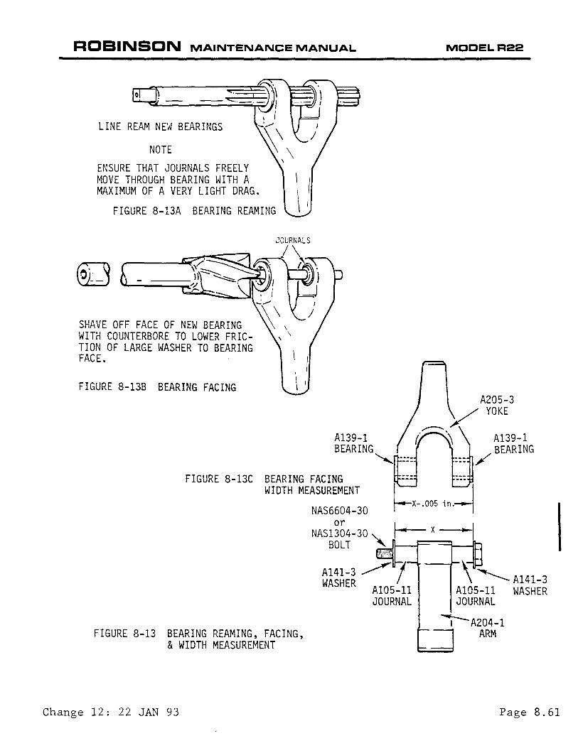
ROBINSON MAINTENANCE MANUAL MOCELR22
NOTE
ENSURE THAT JOURNALS FREELY MOVE THROUGH BEARING WITH A MAXIMUM OF A VERY LIGHT DRAG.
FIGURE 8-13A BEARING REAMING
SHAVE OFF FACE OF NEW BEARING WITH COUNTERBORE TO LOWER FRICTION OF LARGE WASHER TO BEARING FACE.
FIGURE 8-13B BEARING FACING
A139-1
FIGURE 8-13C BEARING FACING WIDTH MEASUREMENT ~X-.005 in.~
FIGURE 8-13 BEARING REAMING, FACING, & WIDTH MEASUREMENT
NAS6604-30
NAS1~~4-30 '-.. I- x -l BOLT '
, \l.ii
A141-3 ~ 7 \ ~ A141-3 WASHER AlOS-11 A105-11 WASHER
JOURNAL JOURNAL
I-A204-1 ARM
I
Change 12: 22 JAN 93 Page 8.61

ROBINSON MAINTENANCE MANUAL MCCELR22
8.620 A139-1 Bearing Installation (cont'd)
e) Measure the distance between the A141-3 washers with the washers held tightly against the journals. Using a one-inch spotface tool with a 0.25 inch pilot, lightly shave the face of each bearing until the measurement across the bearing faces is 0.005 inch less than the measurement between the A141-3 washers. When this dimension is achieved, do not shave any more material off the bearing faces (See Figure 8-13C).
f) Reassemble the yoke or fork assembly and torque the NAS6604 (or NAS1304) bolt to 100 in.-1b plus nut drag. ChecK for freedom of movement with no play or drag.
8.630 B115-1 Bearing Installation
The B115-1 Bearing may be either interference-fit or Loctite®-secured slip-fit in the A203 yoke or A205 fork, depending on the diameter of the bearing bores.
Page 8.62
8. 631 Interference-Fit Bearings ( 0. 6239 I 0. 6244 inch diameter bearing bores)
a) Clean the bearing bores of the yoke or fork assembly. Deburr any sharp edges and inspect and remove any metal shavings in the bearing bores.
b) Heat the yoke or fork assembly to approximately 180 degrees Fahrenheit.
c) Coat one bearing bore with zinc chromate primer. wnile the primer is still wet, press in the B115-1 bearing to the bottom of the bore.
d)
8.632
a)
b)
c)
Coat the other bearing bore with a (Lubri-Kote Type A or equivalent). bearing until it is 0.010 to 0.020 of the bearing bore.
graphite solution Press in the B115-1
inch above the top
Loctite®-secured Slip-Fit Bearings (0.6255/0.6260 inch diameter bearing bores)
Clean the yoke or fork assembly bearing bores of old Loctite®.
Measure the bearing bores; maximum allowable diameter is 0.6260 inch.
Lightly coat the B115-1 bearing outer races with Loctite® 271 compound and install the B115-1 bearings into the bearing bores. Wipe off excess Loctite®. Do not allow Loctite® to enter the B115-1 bearing.
LOCTITE® IS A REGISTERED TRADEMARK OF LOCTITE CORP. NEWINGTON, CT 06111
Change 12: 22 JAN 93
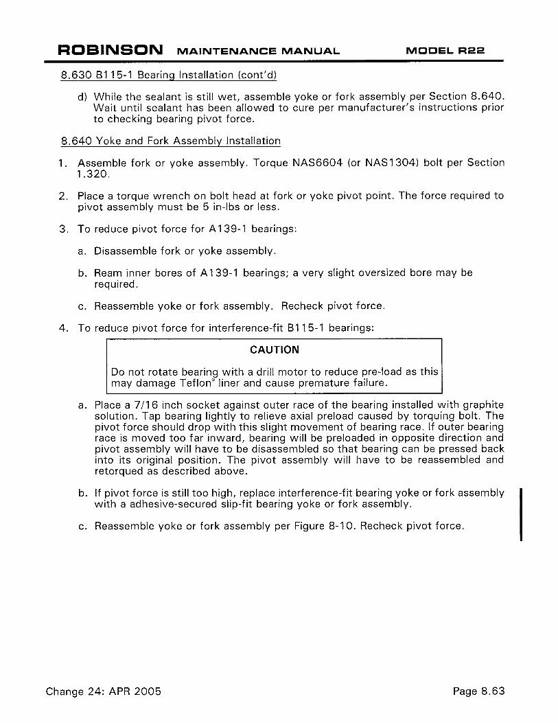
ROBINSON MAINTENANCE MANUAL MODEL R22
8.630 8115-1 Bearing Installation (cont'd)
d) While the sealant is still wet, assemble yoke or fork assembly per Section 8.640. Wait until sealant has been allowed to cure per manufacturer's instructions prior to checking bearing pivot force.
8.640 Yoke and Fork Assembly Installation
1. Assemble fork or yoke assembly. Torque NAS6604 (or NAS1304) bolt per Section 1.320.
2. Place a torque wrench on bolt head at fork or yoke pivot point. The force required to pivot assembly must be 5 in-lbs or less.
3. To reduce pivot force for A 139-1 bearings:
a. Disassemble fork or yoke assembly.
b. Ream inner bores of A 139-1 bearings; a very slight oversized bore may be required.
c. Reassemble yoke or fork assembly. Recheck pivot force.
4. To reduce pivot force for interference-fit 8115-1 bearings:
CAUTION
Do not rotate bearing with a drill motor to reduce pre-load as this may damage Teflon® liner and cause premature failure.
a. Place a 7/16 inch socket against outer race of the bearing installed with graphite solution. Tap bearing lightly to relieve axial preload caused by torquing bolt. The pivot force should drop with this slight movement of bearing race. If outer bearing race is moved too far inward, bearing will be preloaded in opposite direction and pivot assembly will have to be disassembled so that bearing can be pressed back into its original position. The pivot assembly will have to be reassembled and retorqued as described above.
b. If pivot force is still too high, replace interference-fit bearing yoke or fork assembly with a adhesive-secured slip-fit bearing yoke or fork assembly.
c. Reassemble yoke or fork assembly per Figure 8-10. Recheck pivot force.
Change 24: APR 2005 Page 8.63
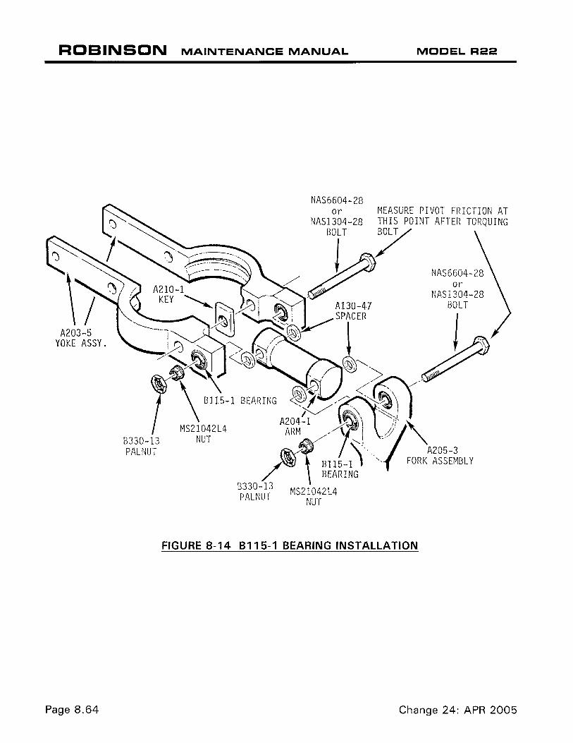
ROBINSON MAINTENANCE MANUAL
A203-5 YOKE ASSY.
8330-13 PAL NUT
NAS6604-28 or
NAS1304-28
MS21042L4 NUT
MODEL R22
NAS6604-28 or
NAS1304-28 BOLT
FIGURE 8-14 8115-1 BEARING INSTALLATION
Page 8.64 Change 24: APR 2005