CHAPTER 8. ENGINES, FUEL, EXHAUST, AND PROPELLERS
17
9/8/98 AC 43.13-1B Par 8-1 Page 8-1 CHAPTER 8. ENGINES, FUEL, EXHAUST, AND PROPELLERS SECTION 1. ENGINES 8-1. GENERAL. Consult the manufac- turer’s manuals, service bulletins, and instruc- tion books regarding the repair and overhaul, inspection, installation, and maintenance of aircraft engines, for that particular make, model, and type of engine. This section lists acceptable inspection and repair procedures that may be used in the absence of an engine manufacturer’s maintenance information. 8-2. SPECIAL INSPECTION. A visual inspection is needed to determine the condition of the engine and its components. An annual or 100-hour inspection should include the en- gine and nacelle group as follows. a. Cold Cylinder Check. If an engine is running rough the cause may be a bad ignition lead, a spark plug not firing, a partially clogged fuel injector, or a bad magneto. The dead cyl- inder will be colder than the surrounding cyl- inders and can be quickly determined by using the recommended cold cylinder checks. This should be done using a thermocouple probe which is very sensitive to small differences in temperature, which is the case with a partially- clogged injector. For a carbureted engine, the following check may be helpful: (1) Using experienced personnel, run the engine on the bad magneto for approxi- mately 30 seconds at 1200 rpm. Without switching the magneto switch back to both shut off the engine. Have another mechanic use a grease pencil (non-carbon), and quickly mark each exhaust stack approximately 1 inch from the flange that holds the exhaust stack to the cylinder. Next, check the exhaust stacks and look for the exhaust stack whose grease pencil mark has not turned to a grayish-white or ash color. This is the cold cylinder. (2) The probable cause of the cold cyl- inder is either a defective spark plug or igni- tion lead. Switch spark plugs to another cylin- der and run the test again. If the problem stays with the original cylinder, the problem is either the ignition lead or the magneto. b. Piston Engine Sudden Stoppage In- spection. Sudden stoppage is a very rapid and complete stoppage of the engine. It can be caused by engine seizure or by one or more of the propeller blades striking an object in such a way that rpm goes to zero in less than one complete revolution of the propeller. Sudden stoppage can cause internal damage to con- stant-speed propellers; reduction drive; gear train damage in the accessory section; crank- shaft misalignment; or damage to accessories such as magnetos, generators, vacuum pumps, and tach generators. (1) Every engine that suffers a sudden stoppage must be inspected in accordance with the manufacturer’s maintenance instructions before being returned to service. (2) If the engine manufacturer does not provide the required information, then the en- gine case must be opened and every major component part must be inspected using visual and/or nondestructive inspection (NDI) proce- dures as applicable. (3) The sudden-stoppage inspections include: checking for cowling, spinner, and airframe cracks and hidden damage; and alignment of the engine mount to the airframe,
Transcript of CHAPTER 8. ENGINES, FUEL, EXHAUST, AND PROPELLERS

9/8/98 AC 43.13-1B
Par 8-1 Page 8-1
CHAPTER 8. ENGINES, FUEL, EXHAUST, AND PROPELLERS
SECTION 1. ENGINES
8-1. GENERAL. Consult the manufac-turer’s manuals, service bulletins, and instruc-tion books regarding the repair and overhaul,inspection, installation, and maintenance ofaircraft engines, for that particular make,model, and type of engine. This section listsacceptable inspection and repair proceduresthat may be used in the absence of an enginemanufacturer’s maintenance information.
8-2. SPECIAL INSPECTION. A visualinspection is needed to determine the conditionof the engine and its components. An annualor 100-hour inspection should include the en-gine and nacelle group as follows.
a. Cold Cylinder Check. If an engine isrunning rough the cause may be a bad ignitionlead, a spark plug not firing, a partially cloggedfuel injector, or a bad magneto. The dead cyl-inder will be colder than the surrounding cyl-inders and can be quickly determined by usingthe recommended cold cylinder checks. Thisshould be done using a thermocouple probewhich is very sensitive to small differences intemperature, which is the case with a partially-clogged injector. For a carbureted engine, thefollowing check may be helpful:
(1) Using experienced personnel, runthe engine on the bad magneto for approxi-mately 30 seconds at 1200 rpm. Withoutswitching the magneto switch back to bothshut off the engine. Have another mechanicuse a grease pencil (non-carbon), and quicklymark each exhaust stack approximately 1 inchfrom the flange that holds the exhaust stack tothe cylinder. Next, check the exhaust stacksand look for the exhaust stack whose grease
pencil mark has not turned to a grayish-whiteor ash color. This is the cold cylinder.
(2) The probable cause of the cold cyl-inder is either a defective spark plug or igni-tion lead. Switch spark plugs to another cylin-der and run the test again. If the problem stayswith the original cylinder, the problem is eitherthe ignition lead or the magneto.
b. Piston Engine Sudden Stoppage In-spection. Sudden stoppage is a very rapid andcomplete stoppage of the engine. It can becaused by engine seizure or by one or more ofthe propeller blades striking an object in such away that rpm goes to zero in less than onecomplete revolution of the propeller. Suddenstoppage can cause internal damage to con-stant-speed propellers; reduction drive; geartrain damage in the accessory section; crank-shaft misalignment; or damage to accessoriessuch as magnetos, generators, vacuum pumps,and tach generators.
(1) Every engine that suffers a suddenstoppage must be inspected in accordance withthe manufacturer’s maintenance instructionsbefore being returned to service.
(2) If the engine manufacturer does notprovide the required information, then the en-gine case must be opened and every majorcomponent part must be inspected using visualand/or nondestructive inspection (NDI) proce-dures as applicable.
(3) The sudden-stoppage inspectionsinclude: checking for cowling, spinner, andairframe cracks and hidden damage; andalignment of the engine mount to the airframe,
AC 43.13-1B 9/8/98
Page 8-2 Par 8-2
the mounting hardware, isolation mounts, andbushings. The aircraft’s firewall must also bechecked for distortion, cracks, and elongatedbolt holes. The damaged propeller must besent to an FAA-certificated repair station forcomplete NDI and repair.
(4) Engine accessories such as: magne-tos, starters, fuel pumps, turbochargers, alter-nators, or generators must be inspected in ac-cordance with the manufacturer’s maintenancemanual on sudden stoppage or overhaul proce-dures to determine the product’s airworthiness.
c. Reciprocating Engine (Direct Drive).Preliminary inspection before tear down.
(1) Remove the engine cowling and ex-amine the engine for visible external damageand audible internal damage.
(2) Rotate the propeller shaft to deter-mine any evidence of abnormal grinding orrubbing sounds.
(3) With the propeller removed, inspectthe crankshaft flange or splines for signs oftwisting, cracks, or other deformation. Re-move the thrust-bearing nut and seal and thor-oughly inspect the threaded area of the shaftfor evidence of cracks.
(4) Rotate the shaft slowly in 90-degreeincrements while using a dial indicator or anequivalent instrument to check the concentric-ity of the shaft.
(5) Remove the oil sump drain plug andcheck for metal chips and foreign material.
(6) Remove the oil screens and inspectfor metal particles and contamination.
(7) Visually inspect engine case exteriorfor signs of oil leaks and cracks. Give
particular attention to the propeller thrust-bearing area of the nose case section.
(8) Inspect cylinders and cylinder hold-down area for cracks and oil leaks. Thor-oughly investigate any indication of cracks, oilleaks, or other damage.
d. Internal Inspection Requirements.
(1) On engines equipped with crank-shaft vibration dampers, remove and inspectthe cylinders, and inspect the crankshaft damp-ers in accordance with the engine manufac-turer’s inspection and overhaul manual. Whenengine design permits, remove the damperpins, and examine the pins and damper linersfor signs of nicks or brinelling.
(2) After removing the engine-drivenaccessories, remove the accessory drive caseand examine the accessory and superchargerdrive gear train, couplings, and drive case forevidence of damage.
(a) Check for cracks in the case inthe area of accessory mount pads and gearshaft bosses.
(b) Check the gear train for signs ofcracked, broken, or brinelled teeth.
(c) Check the accessory drive shaftcouplings for twisted splines, misalignment,and run-out.
(d) Check connecting rods for cracksand straightness.
e. Reciprocating Engine (Gear-Drive).Inspect the engine, propeller, (refer to section 4on propeller inspection), and components asdescribed in the preceding paragraphs.
(1) Remove the propeller reduction gearhousing and inspect for:

9/8/98 AC 43.13-1B
Par 8-2 Page 8-3
(a) Loose, sheared, or spalled capscrews or bolts.
(b) Cracks in the case.
(2) Disassemble the gear train and in-spect the propeller shaft, reduction gears andaccessory drive gears for nicks, cracks, orspalling.
f. Engine-Mount Inspection.
(1) Examine the engine flex mountswhen applicable, for looseness of engine tomount, distortion, or signs of wear.
(2) Inspect the engine-mount structurefor bent, cracked, or buckled tubes.
(3) Check the adjacent airframe struc-ture firewall for cracks, distortion, or wrinkles.
(4) Remove engine-mount bolts andmount hold-down bolts and replace.
g. Exhaust-driven Supercharger(Turbo) Inspection. Sudden stoppage of thepowerplant can cause the heat in turbine partsto heat-soak the turbine seals and bearings.This excessive heat causes carbon to developin the seal area and varnish to form on the tur-bine bearings and journals.
(1) Inspect all air ducts and connectionsfor air leaks, warpage, or cracks.
(2) Remove compressor housing andcheck the turbine wheel for rubbing or binding,and coke or varnish buildup.
NOTE: Turbine turbo superchargerdisk seal rubbing is not unusual andmay be a normal condition. Consultthe engine manufacturer’s inspectionprocedures and table of limits.
h. Accessory and Drive Inspection.Check the drive shaft of each accessory, i.e.,magnetos, generators, external superchargers,and pumps for evidence of damage.
8-3. CRANKSHAFT INSPECTION ANDREPAIR REQUIREMENTS. Carefully in-spect for misalignment and replace if bent be-yond the manufacturer’s permissible servicelimit. Worn journals may be repaired by re-grinding in accordance with manufacturers’ in-structions. It is recommended that grindingoperations be performed by appropriately-ratedrepair stations or the original engine manufac-turer. Common errors that occur in crankshaftgrinding are the removal of nitrided journalsurface, improper journal radii, unsatisfactorysurfaces, and grinding tool marks on the jour-nals. If the fillets are altered, do not reducetheir radii. Polish the reworked surfaces to as-sure removal of all tool marks. Most opposedengines have nitrided crankshafts, and enginemanufacturers specify that these crankshaftsmust be re-nitrided after grinding.
NOTE: Rapid deceleration or mo-mentary slowing of a propeller mayoccur due to contact with tall grass,water, or snow. If this occurs, the en-gine and propeller should be inspectedin accordance with the manufac-turer’s instruction or service bulletins.
8-4. REPLACEMENT PARTS IN CER-TIFICATED ENGINES. Engine replacementparts must be approved under Title 14 of theCode of Federal Regulations (14 CFR),part 21. Serviceable parts obtained from theengine manufacturer, authorized service facil-ity, and those which are approved FederalAviation Administration (FAA)/Parts Manu-facture Approval (PMA), or Technical Stan-dard Order (TSO), and meet the requirementsof part 21 are acceptable for use as replace-ment parts. Used engine parts can be installed
AC 43.13-1B 9/8/98
Page 8-4 Par 8-4
if that part either conforms to new part toler-ances or meets the manufacturer’s service lim-its. Ensure that used parts are airworthy andproperly identified as a PMA or TSO part.
8-5. OIL SYSTEM LINES INSPECTION.The inspection of the plumbing for an oil sys-tem is similar to the inspection of any otherplumbing system. The tubing, hose, tube fit-tings, hose fittings, hose clamps, and all othercomponents of the system are inspected forcracks, holes, dents, bulges, and other signs ofdamage that might restrict the oil flow or causea leak. All lines are inspected to ensure thatthey are properly supported and are not rub-bing against a structure. Fittings should bechecked for signs of improper installation,over-torquing, excessive tension, or other con-ditions which may lead to failure.
8-6. OIL FILTER INSPECTION. The oilfilter provides an excellent method for discov-ering internal engine damage. During the in-spection of the engine oil filter, the residue onthe screens, disks, or disposable filter cartridgeand the residue in the filter housing are care-fully examined for metal particles. A new en-gine or a newly-overhauled engine will oftenhave a small amount of fine metal particles inthe screen or filter, but this is not consideredabnormal. After the engine has been operatedfor a time and the oil has been changed one ormore times, there should not be an appreciableamount of metal particles in the oil screen. Ifan unusual residue of metal particles is foundin the oil screen, the engine must be taken outof service and disassembled to determine thesource of the particles. As an additional pre-caution, an oil analysis/trend analysis may pre-vent an engine failure in flight.At oil changes, oil samples are often taken andsent to laboratories to be analyzed for wear bydetermining the amount of metal in the sam-ple. Over time, a trend is developed and theengine can be removed from service beforefailure.
8-7. CYLINDER HOLD-DOWN NUTSAND CAP SCREWS. Great care is requiredin tightening cylinder hold-down nuts and capscrews. They must be tightened to recom-mended torque limits to prevent improperstressing and to ensure even loading on thecylinder flange. The installation of baffles,brackets, clips, and other extraneous parts un-der nuts and cap screws is not a good practiceand is discouraged. If these baffles, brackets,etc., are not properly fabricated or made ofsuitable material, they may cause loosening ofthe nuts or cap screws even though the nuts orcap screws were properly tightened and lockedat installation. Improper pre-stressing or loos-ening of any one of these nuts or cap screwswill introduce the danger of progressive studfailure with the possible loss of the enginecylinder in flight.
8-8. REUSE OF SAFETYING DEVICES.Do not use cotter pins and safety wire a secondtime. Flat, steel-type wrist pin retainers andlock washers, likewise, must be replaced atoverhaul unless the manufacturer’s recom-mendations permit their reuse.
8-9. SELF-LOCKING NUTS FOR AIR-CRAFT ENGINES AND ACCESSORIES.Self-locking nuts may be used on aircraft en-gines provided the following criteria are met:
a. When their use is specified by the en-gine manufacturer in the assembly drawing,parts list, and bills of material.
b. When the nuts will not fall inside theengine should they loosen and come off.
c. When there is at least one full threadprotruding beyond the nut.
d. Where the temperature will not ex-ceed the maximum limits established for theself-locking material used in the nut. On many
9/8/98 AC 43.13-1B
Par 8-9 Page 8-5
engines the cylinder baffles, rocker box covers,drive covers and pads, and accessory and su-percharger housings are fastened with fiber in-sert lock nuts which are limited to a maximumtemperature of 250 °F. Above this tempera-ture, the fiber insert will usually char and, con-sequently, lose its locking characteristic. Forlocations such as the exhaust pipe attachmentto the cylinder, a locknut which has goodlocking features at elevated temperatures willgive invaluable service. In a few instances, fi-ber insert lock nuts have been approved for useon cylinder hold-down studs. This practice isnot generally recommended, since especiallytight stud fits to the crankcase must be pro-vided, and extremely good cooling must pre-vail so that low temperatures exist where thenut is installed.
e. Information concerning approvedself-locking nuts and their use on specific en-gines are usually found in engine manufac-turer’s manuals or bulletins. If the desired in-formation is not available, it is suggested thatthe engine manufacturer be contacted.
f. Refer to Chapter 7, Aircraft Hardware,Control Cables, and Turnbuckles, for addi-tional information on self-locking nuts.
8-10. METALLIZING. Metallizing inter-nal parts of aircraft engines is not acceptableunless it is proven to the FAA that the metal-lized part will not adversely affect the airwor-thiness of the engine. Metallizing the finnedsurfaces of steel cylinder barrels with alumi-num is acceptable, since many engines areoriginally manufactured in this manner.
8-11. PLATING. Before restoring the plat-ing on any engine part in accordance with themanufacturer’s instructions, the part should bevisually inspected and have an NDI performedbefore any cylinder reconditioning. In general,chromium plating would not be applied tohighly-stressed engine parts. Certain applica-tions of this nature have been found to be satis-
factory; however, engineering evaluation of thedetails for the processes used should be ob-tained.
a. Dense chromium plating of the crank-pin and main journals of some small enginecrankshafts has been found satisfactory, exceptwhere the crankshaft is already marginal instrength. Plating to restore worn, low-stressengine parts, such as accessory drive shaftsand splines, propeller shaft ends, and seatingsurfaces of roller and ball-type bearing races isacceptable but requires compliance withFAA-approved data.
b. Porous chromium-plated walls ofcylinder barrels have been found to be satis-factory for practically all types of engines.Dense or smooth chromium plating, withoutroughened surfaces on the other hand, has notbeen found to be satisfactory.
(1) Cylinder barrel pre-grinding andchromium plating techniques used by themilitary are considered acceptable for all en-gines, and military-approved facilities engagedin doing this work in accordance with militaryspecifications are eligible for approval by theFAA.
(2) Chromium-plated cylinder barrelshave been required for some time to be identi-fied in such a manner that the markings arevisible with the cylinder installed. Military-processed cylinders are banded with orangeenamel above the mounting flange. It has beenthe practice to etch on either the flange edge oron the barrel skirt the processor’s initials andthe cylinder oversize. Most plating facilitiesuse the orange band as well as the permanentidentification marks.
(3) A list of engine and maximum per-missible cylinder barrel oversize are referencedin table 8-1.

AC 43.13-1B 9/8/98
Page 8-6 Par 8-11
TABLE 8-1. Current engine and maximum permissiblecylinder barrel oversize.
Engine manufacturer Engine seriesMax.
oversize(in.)
Air Cooled Motors(Franklin)
No oversize forsleeved cylinders.Solid cylinders........... 0.017
Continental Motors R-670, W-670,R9A....
GTSIO-520, 550........All others....................
0.010 to0.0200.0050.015
Jacobs All.............................. 0.015Kinner All.............................. 0.015Pigman, LeBlond,
Rearwin, KenRoyce
All.............................. 0.025
Lycoming All.............................. 0.010 to0.020
Menasco All.............................. 0.010Pratt & Whitney R-2800B, C, CA, CB..
*R-959 and R-1830....All others....................
0.0250.0300.020
Ranger 6-410 early cyls. 6-3906-410 late cyls. 6-440
(L-440) series..
0.010
0.120
Warner All.............................. 0.015Wright All.............................. 0.020
*(The above oversize limits correspond to themanufacturer’s requirements, except for P&W R-985and R-1830 series engines.)
NOTE: ( Check for latest manufacturer specifications.)
(4) Cylinder barrels which have beenplated by an agency whose process is approvedby the FAA and which have not been workedbeyond maximum permissible limits, will beconsidered acceptable for installation on certi-ficated engines. It will be the responsibility ofthe owner or the repairing agency to providethis proof. In some cases, it may be necessaryto remove cylinders to determine the amountof oversize since this information may beetched on the mating surface of the cylinderbase flange.
8-12. CORROSION. Accomplish corrosionpreventive measures for temporary and long-term storage in accordance with the instruc-tions issued by the pertinent engine manufac-turer. Avoid the use of solutions which con-tain strong caustic compounds and all solu-tions, polishes, cleaners, abrasives, etc., which
might possibly promote corrosive action. (Re-fer to Chapter 6, Corrosion, Inspection, andProtection.)
8-13. ENGINE RUN-IN. After an aircraftengine has been overhauled, it is recom-mended that the pertinent aircraft enginemanufacturer’s run-in instructions be followed.Observe the manufacturer’s recommendationsconcerning engine temperatures and other cri-teria. Repair processes employed during over-haul often necessitate amending the manufac-turer’s run-in procedures. Follow the ap-proved amended run-in procedures in such in-stances.
NOTE: Do not run up engines on theground for long periods of time withthe cowling off. The engine will over-heat because cylinder cooling has beendisrupted.
8-14. COMPRESSION TESTING OFAIRCRAFT ENGINE CYLINDERS. A testto determine the internal condition of the com-bustion chamber cylinder assembly by ascer-taining if any appreciable internal leakage isoccurring is compression testing of aircraft en-gine cylinders. If a cylinder has less than a60/80 reading on the differential test gauges ona hot engine, and procedures in para-graphs 8-15b(5)(i) and (j) fail to raise the com-pression reading, the cylinder must be removedand inspected. To determine the cylinder’sproblem area, have someone hold the propellerat the weak cylinder’s top dead center and withcompressed air still being applied, listen. If airis heard coming out of the exhaust pipe, thecylinder’s exhaust-valve is not seating prop-erly. If air is heard leaking out of the aircleaner/carburetor heat box, the intake valve isleaking. With the oil dipstick removed, and airis rushing out, the piston rings are defective.Remove and repair/overhaul the defectivecylinder.
9/27/01 AC 43.13-1B CHG 1
Par 8-14 Page 8-7
a. Differential Compression Test. Themost common type of compression tester cur-rently in use is the differential pressure-typetester. It provides a cross-reference to validatethe readings obtained and tends to assure thatthe cylinder is defective before it is removed.Before beginning a compression test, considerthe following points:
(1) When the spark plugs are removedfrom the engine, identify them to coincide withthe cylinder and location from which they wereremoved. Close examination of the plugs willreveal the actual operating conditions and aidin diagnosing problems within each individualcylinder.
(2) The operating and maintenance rec-ords of the engine should be reviewed. Rec-ords of previous compression tests are of as-sistance in determining progressive wear con-ditions and help to establish the necessarymaintenance corrective actions.
b. Differential Pressure CompressionTest. The differential pressure tester is de-signed to check the compression of aircraft en-gines by measuring the leakage through thecylinders caused by worn or damaged compo-nents. The operation of the compression testeris based on the principle that, for any given air-flow through a fixed orifice, a constant pres-sure drop across that orifice will result. Therestrictor orifice dimensions in the differentialpressure tester should be sized for the particu-lar engine as follows:
(1) For an engine cylinder having lessthan a 5.00-inch bore; 0.040-inch orifice di-ameter; .250 inch long; and a 60-degree ap-proach angle.
(2) For an engine cylinder with 5.00inch bore and over: 0.060 inch orifice diame-ter, .250 inch long, 60 degree approach angle.
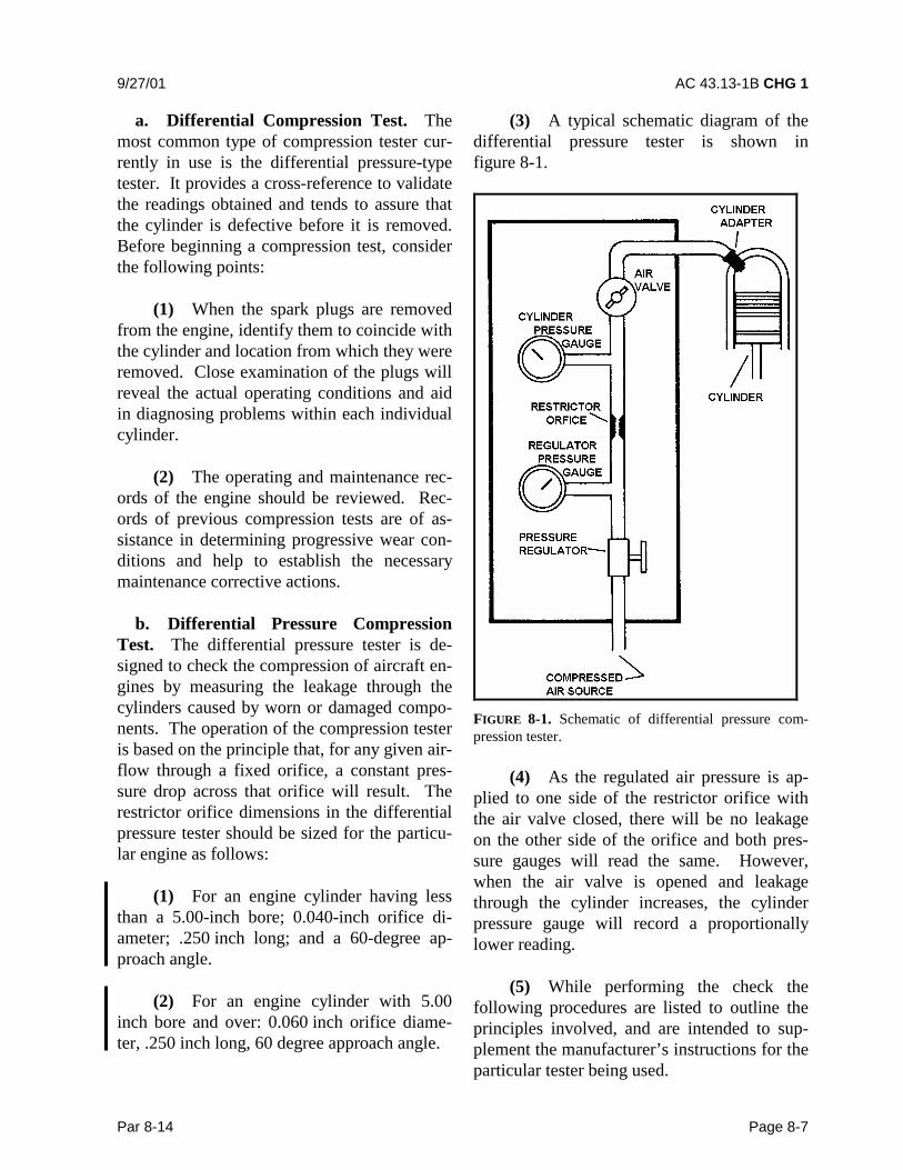
(3) A typical schematic diagram of thedifferential pressure tester is shown infigure 8-1.
FIGURE 8-1. Schematic of differential pressure com-pression tester.
(4) As the regulated air pressure is ap-plied to one side of the restrictor orifice withthe air valve closed, there will be no leakageon the other side of the orifice and both pres-sure gauges will read the same. However,when the air valve is opened and leakagethrough the cylinder increases, the cylinderpressure gauge will record a proportionallylower reading.
(5) While performing the check thefollowing procedures are listed to outline theprinciples involved, and are intended to sup-plement the manufacturer’s instructions for theparticular tester being used.

AC 43.13-1B 9/8/98
Page 8-8 Par 8-14
(a) Perform the compression test assoon as possible after the engine is shut downto ensure that the piston rings, cylinder walls,and other engine parts are well-lubricated.
(b) Remove the most accessiblespark plug from each cylinder.
(c) With the air valve closed, applyan external source of clean air (approximately100 to 120 psi) to the tester.
(d) Install an adapter in the sparkplug bushing and connect the compressiontester to the cylinder.
(e) Adjust the pressure regulator toobtain a reading of 20 psi on the regulatorpressure gauge. At this time, the cylinderpressure gauge should also register 20 psi.
(f) Turn the crankshaft, by hand, inthe direction of rotation until the piston (in thecylinder being checked) is coming up on itscompression stroke. Slowly open the air valveand pressurize the cylinder to 80 psi.
CAUTION: Care must be exercisedin opening the air valve since suffi-cient air pressure will have built up inthe cylinder to cause it to rapidly ro-tate the propeller if the piston is not attop dead center (TDC).
(g) Continue rotating the engineagainst this pressure until the piston reachesTDC. Reaching TDC is indicated by a flatspot or sudden decrease in force required toturn the crankshaft. If the crankshaft is rotatedtoo far, back up at least one-half revolutionand start over again to eliminate the effect ofbacklash in the valve operating mechanism andto keep piston rings seated on the lower ringlands.
(h) Open the air valve completely.Check the regulated pressure and readjust, ifnecessary, to read 80 psi.
(i) Observe the pressure indication ofthe cylinder pressure gauge. The differencebetween this pressure and the pressure shownby the regulator pressure gauge is the amountof leakage through the cylinder. A loss in ex-cess of 25 percent of the input air pressure iscause to suspect the cylinder of being defec-tive; however, recheck the readings after oper-ating the engine for at least 3 minutes to allowfor sealing of the rings with oil.
(j) If leakage is still occurring after arecheck, it may be possible to correct a lowreading. This is accomplished by placing a fi-ber drift on the rocker arm directly over thevalve stem and tapping the drift several timeswith a hammer to dislodge any foreign mate-rial between the valve face and seat.
NOTE: When correcting a low read-ing in this manner, rotate the propel-ler so the piston will not be at TDC.This is necessary to prevent the valvefrom striking the top of the piston insome engines. Rotate the engine be-fore rechecking compression to reseatthe valves in the normal manner.
8-15. SPARK PLUGS. The spark plug pro-vides the high-voltage electrical spark to ignitethe fuel/air mixture in the cylinder. The typesof spark plugs used in different engines willvary with regard to heat range, reach, threadsize, and other characteristics required by theparticular installation.
a. Heat Range. The heat range of a sparkplug is the principal factor governing aircraftperformance under various service conditions.The term “heat range” refers to the

9/8/98 AC 43.13-1B
Par 8-15 Page 8-9
classification of spark plugs according to theirability to transfer heat from the firing end ofthe spark plug to the cylinder head.
(1) Spark plugs have been classified as“hot,” “normal,” and “cold.” However, theseterms may be misleading because the heatrange varies through many degrees of tem-perature from extremely hot to extremely cold.Thus the words “hot,” “cold,” and “normal” donot necessarily tell the whole story.
(2) Since the insulator is designed to bethe hottest part of the spark plug, its tempera-ture can be related to the pre-ignition andfouling regions as shown in figure 8-2. Pre-ignition is likely to occur if surface areas in thecombustion chamber exceed critical limits or ifthe spark plug core nose temperature exceeds1,630 °F (888 °C). However, fouling or short-circuiting of the plug due to carbon deposits islikely to occur if the insulator tip temperaturedrops below approximately 800 °F (427 °C).Since spark plugs must operate between fairlywell-defined temperature limits, they must besupplied in various heat ranges to meet the re-quirements of different engines under a varietyof operating conditions.
FIGURE 8-2. Chart of spark plug temperature ranges.
(3) From the engineering standpoint,each individual plug must be designed to offerthe widest possible operating range. Thismeans that a given type of spark plug should
operate as hot as possible at low speeds andlight loads and as cool as possible undercruising and takeoff power. Plug performance,therefore, depends on the operating tempera-ture of the insulator nose, with the most desir-able temperature range falling between1,000 °F and 1,250 °F (538 °C and 677 °C).
(4) Fundamentally, an engine whichruns hot requires a relatively cold spark plug,whereas an engine which runs cool requires arelatively hot spark plug. If a hot spark plug isinstalled in an engine which runs hot, the sparkplug tip will be overheated and cause pre-ignition. If a cold spark plug is installed in anengine which runs cool, the tip of the sparkplug will collect unburned carbon, causingfouling of the plug. The principal factors gov-erning the heat range of aircraft spark plugsare:
(a) the distance between the coppersleeve around the insulator and the insulatortip;
(b) the thermal conductivity of theinsulating material;
(c) the thermal conductivity of theelectrode;
(d) the rate of heat transfer betweenthe electrode and the insulator;
(e) the shape of the insulator tip;
(f) the distance between the insulatortip and the shell; and
(g) the type of outside gasket used.
(5) “Hot” plugs have a long insulatornose; thereby, creating a long heat transferpath, whereas “cold” plugs have a relativelyshort insulator to provide a rapid transfer ofheat to the cylinder head. (See figure 8-3.)

AC 43.13-1B 9/8/98
Page 8-10 Par 8-15
FIGURE 8-3. Hot and cold spark plugs.
b. Reach. The spark plug reach (see fig-ure 8-4) is the threaded portion which is in-serted into the spark plug bushing of the cylin-der. A plug with the proper reach will ensurethat the electrode end inside the cylinder is inthe best position to achieve ignition. Sparkplug seizure or improper combustion withinthe cylinder will probably occur if a plug withthe wrong reach is used. Shell threads of sparkplugs are classified as 14- or 18-mm sparkplug diameter, long reach or short reach, thus:
Diameter Long reach Short reach14 mm 1/2 in (12.7 mm) 3/8 in (9.53 mm)18 mm 13/16 in. (20.64 mm) 1/2 in (12.7 mm)
FIGURE 8-4. Spark plug reach.
c. Installation Procedures. When in-stalling spark plugs, observe the followingprocedure.
(1) Visually inspect the plug for clean-liness and condition of the threads, ceramic,and electrodes.
NOTE: Never install a spark plugwhich has been dropped and alwaysuse new gaskets every time you installa spark plug.
(2) Check the plug for the proper gapsetting, using a round wire feeler gauge asshown in figure 8-5. In the case of used plugs,procedures for cleaning and regapping are usu-ally contained in the various manufacturers’manuals.
FIGURE 8-5. Method of checking spark plug gap.
(3) Check the plug and cylinder bushingto ascertain that only one gasket is used perspark plug. When a thermocouple-type gasketis used, no other gasket is required.
(4) Apply anti-seize compound spar-ingly to the shell threads, but do not allow thecompound to contact the electrodes since thematerial is conductive and will short out the

9/8/98 AC 43.13-1B
Par 8-15 Page 8-11
plug. If desired, the use of anti-seize com-pound may be eliminated on engines equippedwith stainless steel spark plug bushings orinserts.
(5) Screw the plug into the cylinderhead as far as possible by hand. If the plugwill not turn easily to within two or threethreads of the gasket, it may be necessary toclean the threads.
NOTE: Cleaning inserts with a tap isnot recommended as permanent dam-age to the insert may result.
(6) Seat the proper socket securely onthe spark plug and tighten to the torque limitspecified by the engine manufacturer beforeproceeding to the next plug.
CAUTION: A loose spark plug willnot transfer heat properly, and duringengine operation, may overheat to thepoint the nose ceramic will become a“hot spot” and cause pre-ignition.However, avoid over-tightening asdamage to the plug and bushing mayresult.
(7) Connect the ignition lead after wip-ing clean with a dry, lint-free cloth. Insert theterminal assembly into the spark plug in astraight line. (Care should be taken as im-proper techniques can damage the terminalsleeves.) Screw the connector nut into placeuntil finger tight, then tighten an additionalone quarter turn while holding the elbow in theproper position.
(8) Perform an engine run-up after in-stalling a new set of spark plugs. When theengine has reached normal operating tempera-tures, check the magnetos and spark plugs inaccordance with the manufacturer’s instruc-tions.
8-16. OPERATIONAL PROBLEMS.Whenever problems develop during engineoperation, which appear to be caused by theignition system, it is recommended that thespark plugs and ignition harnesses be checkedfirst before working on the magnetos. Thefollowing are the more common spark plugmalfunctions and are relatively easy to iden-tify.
a. Fouling.
(1) Carbon fouling (see figure 8-6) isidentified by the dull black, sooty deposits onthe electrode end of the plug. Although theprimary causes are excessive ground idling andrich idle mixtures, a cold heat range may alsobe a contributing factor.
(2) Lead fouling is characterized byhard, dark, cinder-like globules which gradu-ally fill up the electrode cavity and short outthe plug. (See figure 8-6a.) The primary causefor this condition is poor fuel vaporizationcombined with a high tetraethyl-lead contentfuel. A cold heat range may also contribute tothis condition.
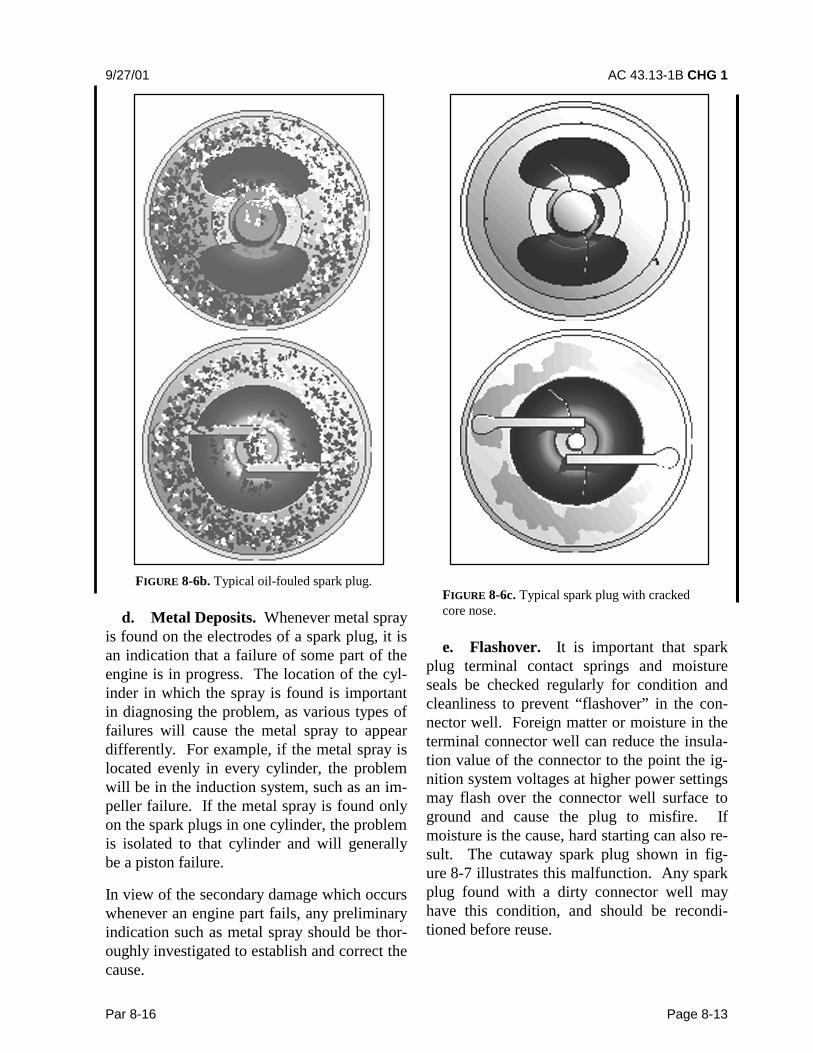
(3) Oil fouling is identified by a wet,black carbon deposit over the entire firing endof the plug as shown in figure 8-6b. This con-dition is fairly common on the lower plugs inhorizontally-opposed engines, and both plugsin the lower cylinders of radial engines. Oilfouling is normally caused by oil drainage pastthe piston rings after shutdown. However,when both spark plugs removed from the samecylinder are badly fouled with oil and carbon,some form of engine damage should be sus-pected, and the cylinder more closely in-spected. Mild forms of oil fouling can usuallybe cleared up by slowly increasing power,while running the engine until the deposits areburned off and the misfiring stops.

AC 43.13-1B CHG 1 9/27/01
Page 8-12 Par 8-16
FIGURE 8-6. Typical carbon-fouled spark plug.
b. Fused Electrodes. There are many dif-ferent types of malfunctions which result infused spark plug electrodes; however, most areassociated with pre-ignition either as the causeor the effect. For this reason, any time a sparkplug is found with the following defects, fur-ther investigation of the cylinder and pistonshould be conducted.
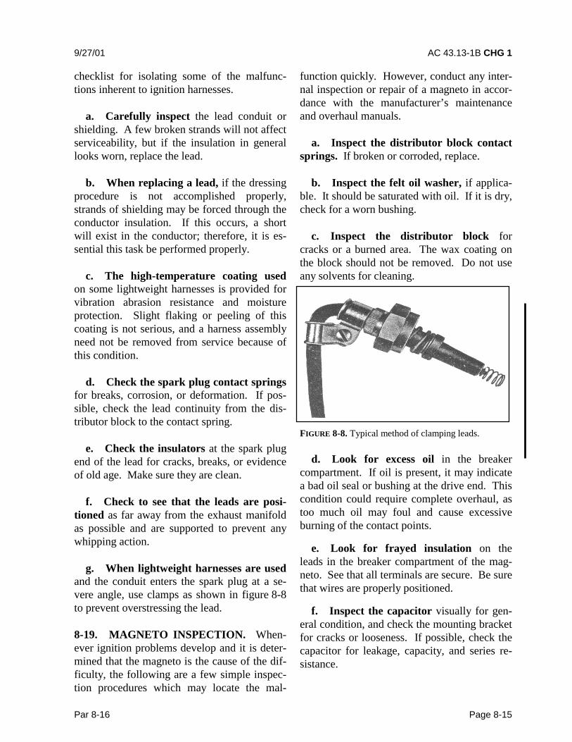
(1) Occasionally, the ceramic nose corewill crack, break away, and remain trapped be-hind the ground electrode. This piece of insu-lation material will then buildup heat to thepoint it will ignite the fuel/air mixture prema-turely. The high temperatures and pressuresencountered during this condition can causedamage to the cylinder and piston and ulti-mately lead to fusing and shorting out of theplug. (See figure 8-6c.)
FIGURE 8-6a. Typical lead-fouled spark plug.
(2) Corrosive gases formed by combus-tion and the high voltage spark have eroded theelectrodes. Spark plugs in this condition re-quire more voltage to fire—often more thanthe ignition system can produce. (See fig-ure 8-6d.)
c. Bridged Electrodes. Occasionally, freecombustion chamber particles will settle on theelectrodes of a spark plug and gradually bridgethe electrode gap, resulting in a shorted plug.Small particles may be dislodged by slowlycycling the engine as described for the oil-fouled condition; however, the only remedy formore advanced cases is removal and replace-ment of the spark plug. This condition isshown in figure 8-6e.
9/27/01 AC 43.13-1B CHG 1
Par 8-16 Page 8-13
FIGURE 8-6b. Typical oil-fouled spark plug.
d. Metal Deposits. Whenever metal sprayis found on the electrodes of a spark plug, it isan indication that a failure of some part of theengine is in progress. The location of the cyl-inder in which the spray is found is importantin diagnosing the problem, as various types offailures will cause the metal spray to appeardifferently. For example, if the metal spray islocated evenly in every cylinder, the problemwill be in the induction system, such as an im-peller failure. If the metal spray is found onlyon the spark plugs in one cylinder, the problemis isolated to that cylinder and will generallybe a piston failure.
In view of the secondary damage which occurswhenever an engine part fails, any preliminaryindication such as metal spray should be thor-oughly investigated to establish and correct thecause.
FIGURE 8-6c. Typical spark plug with crackedcore nose.
e. Flashover. It is important that sparkplug terminal contact springs and moistureseals be checked regularly for condition andcleanliness to prevent “flashover” in the con-nector well. Foreign matter or moisture in theterminal connector well can reduce the insula-tion value of the connector to the point the ig-nition system voltages at higher power settingsmay flash over the connector well surface toground and cause the plug to misfire. Ifmoisture is the cause, hard starting can also re-sult. The cutaway spark plug shown in fig-ure 8-7 illustrates this malfunction. Any sparkplug found with a dirty connector well mayhave this condition, and should be recondi-tioned before reuse.

AC 43.13-1B CHG 1 9/27/01
Page 8-14 Par 8-19
FIGURE 8-6d. Typical worn out spark plug.
8-17. SPARK PLUG PRE-RECONDI-TIONING INSPECTION. All spark plugsshould be inspected visually before recondi-tioning to eliminate any plug with obvious de-fects. A partial checklist of common defectsincludes:
a. Chipped or cracked ceramic either atthe nose core or in the connector well.
b. Damaged or badly worn electrodes.
c. Badly nicked, damaged, or corrodedthreads on shell or shielding barrel.
d. Dented, bent, or cracked shieldingbarrel.
e. Connector seat at the top of theshielding barrel badly nicked or corroded.
FIGURE 8-6e. Typical spark plug with bridged electrodes.
FIGURE 8-7. Spark plug well flashover.
8-18. IGNITION HARNESSES INSPEC-TION. Aircraft-quality ignition harness isusually made of either medium or high-temperature wire. The type used will dependupon the manufacturing specification for theparticular engine. In addition to the applicablemanufacturer’s maintenance and repair proce-dures, the following is a quick-reference
9/27/01 AC 43.13-1B CHG 1
Par 8-16 Page 8-15
checklist for isolating some of the malfunc-tions inherent to ignition harnesses.
a. Carefully inspect the lead conduit orshielding. A few broken strands will not affectserviceability, but if the insulation in generallooks worn, replace the lead.
b. When replacing a lead, if the dressingprocedure is not accomplished properly,strands of shielding may be forced through theconductor insulation. If this occurs, a shortwill exist in the conductor; therefore, it is es-sential this task be performed properly.
c. The high-temperature coating usedon some lightweight harnesses is provided forvibration abrasion resistance and moistureprotection. Slight flaking or peeling of thiscoating is not serious, and a harness assemblyneed not be removed from service because ofthis condition.
d. Check the spark plug contact springsfor breaks, corrosion, or deformation. If pos-sible, check the lead continuity from the dis-tributor block to the contact spring.
e. Check the insulators at the spark plugend of the lead for cracks, breaks, or evidenceof old age. Make sure they are clean.
f. Check to see that the leads are posi-tioned as far away from the exhaust manifoldas possible and are supported to prevent anywhipping action.
g. When lightweight harnesses are usedand the conduit enters the spark plug at a se-vere angle, use clamps as shown in figure 8-8to prevent overstressing the lead.
8-19. MAGNETO INSPECTION. When-ever ignition problems develop and it is deter-mined that the magneto is the cause of the dif-ficulty, the following are a few simple inspec-tion procedures which may locate the mal-
function quickly. However, conduct any inter-nal inspection or repair of a magneto in accor-dance with the manufacturer’s maintenanceand overhaul manuals.
a. Inspect the distributor block contactsprings. If broken or corroded, replace.
b. Inspect the felt oil washer, if applica-ble. It should be saturated with oil. If it is dry,check for a worn bushing.
c. Inspect the distributor block forcracks or a burned area. The wax coating onthe block should not be removed. Do not useany solvents for cleaning.
FIGURE 8-8. Typical method of clamping leads.
d. Look for excess oil in the breakercompartment. If oil is present, it may indicatea bad oil seal or bushing at the drive end. Thiscondition could require complete overhaul, astoo much oil may foul and cause excessiveburning of the contact points.
e. Look for frayed insulation on theleads in the breaker compartment of the mag-neto. See that all terminals are secure. Be surethat wires are properly positioned.
f. Inspect the capacitor visually for gen-eral condition, and check the mounting bracketfor cracks or looseness. If possible, check thecapacitor for leakage, capacity, and series re-sistance.

AC 43.13-1B 9/8/98
Page 8-16 Par 8-19
g. Examine the points for excessive wearor burning. Discard points which have deeppits or excessively burned areas. Desiredcontact surfaces have a dull gray, sandblasted(almost rough) or frosted appearance over thearea where electrical contact is made. Fig-ure 8-9 shows how the normal contact pointwill look when surfaces are separated for in-spection. Minor irregularities or roughness ofpoint surfaces are not harmful (see fig-ure 8-10), neither are small pits or mounds, ifnot too pronounced. If there is a possibility ofthe pit becoming deep enough to penetrate thepad (see figure 8-11), reject the contact assem-bly.
FIGURE 8-9. Normal contact point.
FIGURE 8-10. Point with minor irregularities.
h. Generally, no attempt should bemade to dress or stone contact point assem-blies; however, if provided, procedures andlimits contained in the manufacturer’s manualsmay be followed.
FIGURE 8-11. Point with well-defined mound.
CAUTION: When inspecting the con-tact points for condition, do not openfurther than absolutely necessary.Excess tension on the spring willweaken it and adversely affect theperformance of the magneto.
i. Adjustment of magneto point gapsmust be correct for proper internal timing of amagneto. See applicable manufacturer’s pub-lications for internal timing procedures.
j. Check the breaker cam to assurecleanness and smoothness. Check the camscrew for tightness. If new points have beeninstalled, blot a little oil on the cam. In addi-tion, check contact point assembly to ascertainthat the cam follower is securely fastened.
k. If the impulse coupling is accessible,inspect for excessive wear on the contact edgesof the body and flyweights. In addition, checkthe flyweights for looseness on the axles.
l. Further examination of the impulsecoupling body may disclose cracks caused byexceedingly-tight flyweight axle rivets.
m. Check the magneto ventilators forproper functioning and obstructions. If drilledplugs are used, they should be in the lowestvent hole of the magneto to serve as a drain forcondensation and oil.

9/8/98 AC 43.13-1B
Par 8-20 Page 8-17 (and 8-18)
8-20. MAGNETO-TO-ENGINE TIMING.While the actual process of timing magnetos toan engine is covered in the engine manufac-turer’s technical manuals, the following gen-eral procedures may be applied.
a. Before installing a new magneto, thecorrect “E” gap setting specified by the mag-neto manufacturer should be verified.
b. When setting or checking the mag-neto-to-engine timing, always turn the crank-shaft steadily in the normal direction of rota-tion to eliminate any error caused by gearbacklash.
c. Recheck magneto-to-engine timingafter any point-gap adjustment, or after re-placement of the breaker points.
d. Never advance the magneto timingbeyond the engine timing specification rec-ommended by the engine manufacturer.
e. The possibility of a timing error ex-ists if a timing indicator which attaches to thepropeller shaft or spinner of geared engines isused. Engine timing specifications are alwaysgiven in degrees of crankshaft travel and can-not be applied directly to geared propellershafts because of the gear ratio. Therefore, thecorrect position of the propeller shaft, if usedfor timing, must be determined by multiplyingthe crankshaft timing angle in degrees beforetop center (BTC) by the propeller gear ratio.
8-21. 8-29. [RESERVED.]