CHAPTER 8 CONSTRUCTION SURVEYS · Sec. 8.06 Culvert Stakeout ... All pipe culverts, 48”and...
37
CHAPTER 8 CONSTRUCTION SURVEYS Chapter Contents Sec. 8.01 General Sec. 8.02 Alignment Sec. 8.03 Levels, Benchmarks & Project Elevations Sec. 8.04 DTM’s Sec. 8.05 Borrow Pits Sec. 8.06 Culvert Stakeout Sec. 8.07 Bridge Stakeout Sec. 8.08 Slope Stakes Sec. 8.09 Fine Grade Stakes Sec. 8.10 Right-of-Way Stakes Sec. 8.11 Federal Aid State Force Account Projects Sec. 8.12 No Plan Projects Sec. 8.13 Minimum Plan Projects Sec. 8.14 Condemnation Staking Sec. 8.15 As-built Plan of Right-of-Way Monumentation Sec. 8.16 Submitting Survey Data Sec. 8.17 105.13 & 517 Construction Manual
-
Upload
phungduong -
Category
Documents
-
view
245 -
download
7
Transcript of CHAPTER 8 CONSTRUCTION SURVEYS · Sec. 8.06 Culvert Stakeout ... All pipe culverts, 48”and...

CHAPTER 8
CONSTRUCTION SURVEYS
Chapter Contents
Sec. 8.01 General Sec. 8.02 Alignment Sec. 8.03 Levels, Benchmarks & Project Elevations Sec. 8.04 DTM’s Sec. 8.05 Borrow Pits Sec. 8.06 Culvert Stakeout Sec. 8.07 Bridge Stakeout Sec. 8.08 Slope Stakes Sec. 8.09 Fine Grade Stakes Sec. 8.10 Right-of-Way Stakes Sec. 8.11 Federal Aid State Force Account Projects Sec. 8.12 No Plan Projects Sec. 8.13 Minimum Plan Projects Sec. 8.14 Condemnation Staking Sec. 8.15 As-built Plan of Right-of-Way Monumentation Sec. 8.16 Submitting Survey Data Sec. 8.17 105.13 & 517 Construction Manual

8-1
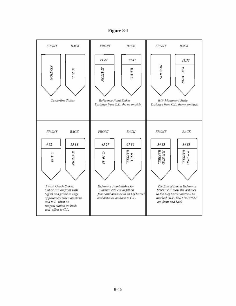
Sec. 8.01 General Construction surveys shall be made in accordance with the General Provision in Section 105.13 & 517 of the Road and Bridge Specifications and the Construction Manual with its corresponding sections. The Contract Surveyor or District Survey Manager (whichever is performing the stakeout) should become familiar with the plans, Road and Bridge Specifications, and contract prior to the Pre-Construction Conference so any concerns can be addressed at that meeting. Unless specifically instructed by the District Survey Manager, the Survey Crew is not to perform checks on any survey work performed by the contractor. Sec. 8.02 Alignment The construction centerline shall be established using the alignment data sheet and the established coordinate values that are included in the plan set. All control points used during construction stakeout should be referenced and recorded for future use. Any discrepancies in the construction alignment should be brought to the immediate attention of the project inspector. All notes relative to the retracing of the plan alignment shall be recorded in the digital, ASCII file, or field book in the standard manner, and should be retained by the survey party for the use of retracing the line after construction, if needed (Figures 8-B through 8-D). For marking centerline and reference stakes, please see Figure 8-I. Sec. 8.03 Levels, Benchmarks and Project Elevations Project benchmarks are shown on the alignment data sheet in the plan set. These benchmarks should be checked prior to their use in stakeout. Differential leveling should be run between benchmarks and recorded in field notes. Any appreciable differences in benchmark elevation should be recorded in field notes and check levels should be run to verify the difference. The project inspector should be notified of the discrepancies so he can notify the District Survey Manager. If additional benchmarks are set on the project, a list of these benchmarks with a description and elevation should be given to the project inspector and contractor. For examples of level notes see Figures 8F, 8G, and 8H. Sec. 8.04 DTM’s DTM’s will not be required on plan quantity projects. Of the majority of projects currently designed, regular excavation is plan quantity. For those projects that are designed as non-plan quantity, then original ground DTM’s will need to be secured during the slope stake process. These will be done so accurate excavation quantities can be computed for the project. In these rare instances, the District Survey Manager can be contacted for proper procedures in securing DTM’s.

8-2
The Department analyzes topographic information by using a Digital Terrain Model (DTM), or a triangulated network of 3-Dimensional points for representing existing terrain. Volumetric computations are performed accurately and more cost-effectively using a DTM than by the traditional field cross-section methods. DTMs are acceptable to VDOT for determining volumetric information. There have been occasions when ground elevations have changed in certain areas on construction projects. In preparation for slope staking, sufficient checks should be made throughout the project to verify original ground elevations. If any areas are found that have appreciable variations in ground elevations within the project limits then the project inspector should be notified and DTM’s should be secured in those areas to provide for computations of accurate quantities. If DTM’s are to be used then the District Survey Manager should be contacted by the project inspector to make sure that the electronic format that the surveyor uses in securing this information is compatible with the Department software. DTM’s will be based on plan elevations and coordinate values or electronic DTM file shall be given to the project inspector so he can give this information to the Design Section so new quantities can be computed. Cross Sections are no longer used in construction surveys. In lieu of securing cross-section information, a DTM surface is the accepted VDOT format for determining volumetric and grading information. I case of emergency or a special situation, cross sections can be requested. (Figures 8-A & 8-E). After centerline elevations have been secured and checked where necessary, DTM’s shall be secured at all stations, intermediate intervals and at all appreciable breaks in the ground. In all cases, the DTM’s shall be based on the plan construction centerline. DTM surfaces have made cross sections on multiple alignments obsolete. An adequate DTM surface with points and break lines will suffice. Sec. 8.05 Borrow Pits Borrow pits will be surveyed by VDOT survey crews, but the Survey Party Manager (Land Surveyor) should encourage the contractor to have his personnel or hire a survey crew to check behind the Department. Discrepancy in borrow quantities will not be considered unless supporting survey data was obtained by contractor to substantiate the claim. If borrow material is shown on the plans, the Project Inspector should contact the District Survey Manager when the borrow pit location has been approved and properly prepared. All borrow pits shall have DTM’s collected using the elevation of a benchmark shown on the plans if possible, if not, then a minimum of two benchmarks should be set and assumed elevations may be used. A diagram of all borrow pits shall be shown in the borrow pit notebooks or digital file giving the number of each pit, property owner's name, property lines, the definite location, distance from centerline of the road and a tie-in with definite stations, if possible. If the quantities are to be run through the computer, the number of baselines and their intervals can be set up solely for the convenience of the survey party in taking DTM’s.
8-3
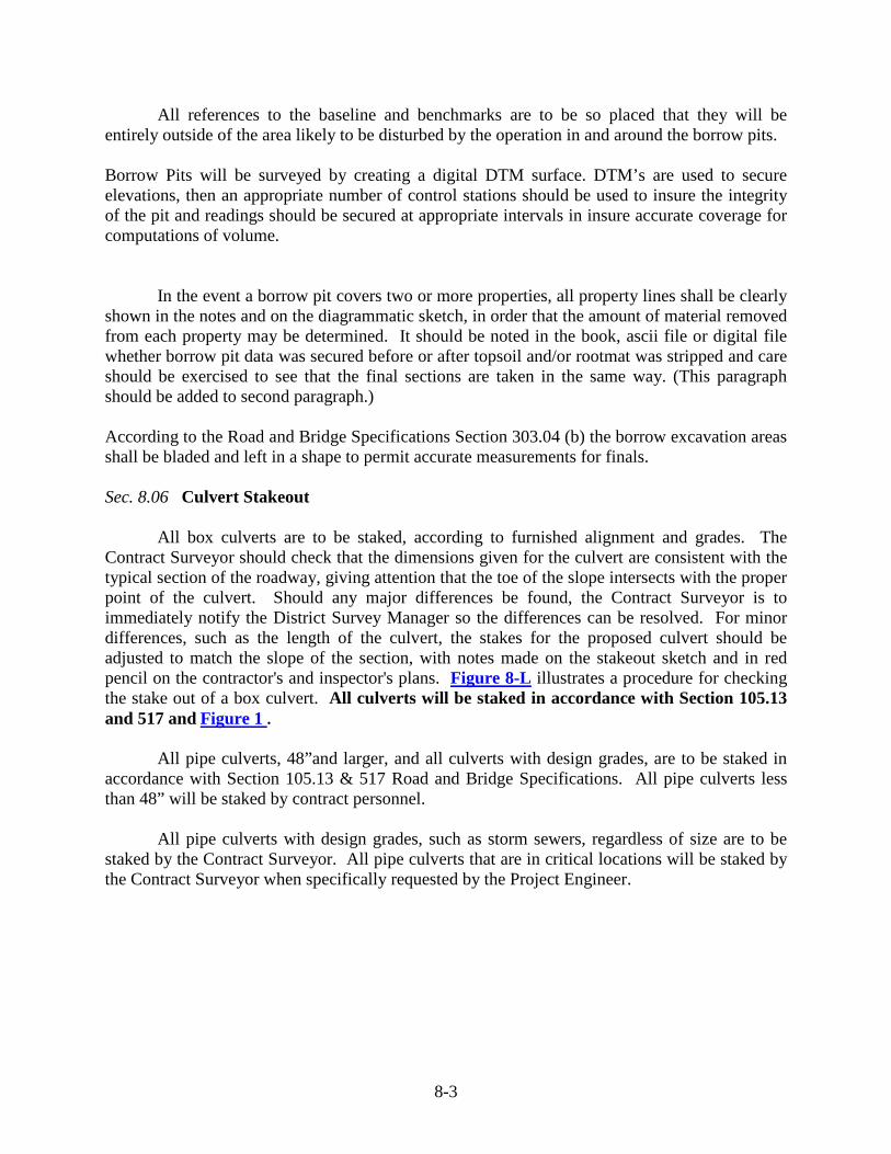
All references to the baseline and benchmarks are to be so placed that they will be entirely outside of the area likely to be disturbed by the operation in and around the borrow pits. Borrow Pits will be surveyed by creating a digital DTM surface. DTM’s are used to secure elevations, then an appropriate number of control stations should be used to insure the integrity of the pit and readings should be secured at appropriate intervals in insure accurate coverage for computations of volume. In the event a borrow pit covers two or more properties, all property lines shall be clearly shown in the notes and on the diagrammatic sketch, in order that the amount of material removed from each property may be determined. It should be noted in the book, ascii file or digital file whether borrow pit data was secured before or after topsoil and/or rootmat was stripped and care should be exercised to see that the final sections are taken in the same way. (This paragraph should be added to second paragraph.) According to the Road and Bridge Specifications Section 303.04 (b) the borrow excavation areas shall be bladed and left in a shape to permit accurate measurements for finals. Sec. 8.06 Culvert Stakeout All box culverts are to be staked, according to furnished alignment and grades. The Contract Surveyor should check that the dimensions given for the culvert are consistent with the typical section of the roadway, giving attention that the toe of the slope intersects with the proper point of the culvert. Should any major differences be found, the Contract Surveyor is to immediately notify the District Survey Manager so the differences can be resolved. For minor differences, such as the length of the culvert, the stakes for the proposed culvert should be adjusted to match the slope of the section, with notes made on the stakeout sketch and in red pencil on the contractor's and inspector's plans. Figure 8-L illustrates a procedure for checking the stake out of a box culvert. All culverts will be staked in accordance with Section 105.13 and 517 and Figure 1 . All pipe culverts, 48”and larger, and all culverts with design grades, are to be staked in accordance with Section 105.13 & 517 Road and Bridge Specifications. All pipe culverts less than 48” will be staked by contract personnel. All pipe culverts with design grades, such as storm sewers, regardless of size are to be staked by the Contract Surveyor. All pipe culverts that are in critical locations will be staked by the Contract Surveyor when specifically requested by the Project Engineer.

8-4
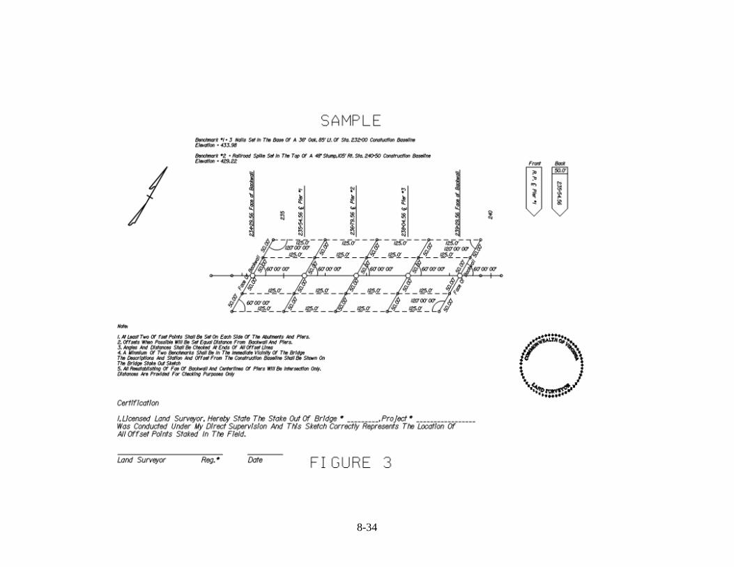
Sec. 8.07 Bridge Stakeout The Contract Surveyor should check the consistency between the stations and the dimensions given on the bridge plans. If any difference is found, the Contract Surveyor should immediately notify the District Survey Manager and the District Structure & Bridge Engineer so that the differences can be resolved. This check is necessary on all grade separation structures to insure that the substructure is correctly located with respect to railroad tracks or under passing roads before construction is started. The Contract Surveyor is to set stakes at the intersection of the baseline of the bridge and the centerline of each pier. Also, stakes shall be set on the baseline of the bridge at the intersection of the lines shown on the plans on the abutments from which dimensions are referenced. These intersection points will be shown on the sub-structure layout sheet of the bridge plans. Angles are to be turned to the centerline of all piers and the lines shown on the plans on the abutments from which dimensions are referenced and stakes set on either of the bridge baseline on these centerlines. All bridge staking shall be in accordance with Section 105.13 and 517, Figure 8J, and Figures 2 & 3 . All measurements of distances and angles are to be checked thoroughly by the Contract Surveyor using a different method than that used initially. After completing the stakeout and thoroughly checking the same, the Contract Surveyor shall locate in red pencil on the layout sheet of the bridge plans used by the Project Inspector, and Contractor's Superintendent all points which have been staked. This should be done in the presence of the Project Inspector and the Contractor's Superintendent or Engineer. The Contract Surveyor shall set an adequate number of stakes at 25’ intervals or less to locate the position of the toe of fill (or cut) in front of the two abutments. The Contract Surveyor should be certain that the road and bridge plans agree as to dimensions, rates of slope and super elevation on the abutment slopes. Sec. 8.08 Slope Stakes Slope stakes shall be set at all stations in accordance with the latest standards. The correct method of marking and setting slope stakes is shown in Figure 8-K. For information on producing slope stakes notes, see Figures 8-E through 8-G. A careful examination should be made of the typical sections as shown, in regard to width of surfacing, width of shoulder and width of ditch, together with the cut or fill slopes or CS standards used. Also, a careful examination should be made of the summary sheets, plan sheets, profile sheets, special notes pertaining to the staking and construction of the project, and the plan cross-sections to determine the suggested slope to be used in special cases. In case of a conflict, the District Survey Manager will contact the Design Unit for clarification and when such clarification is given, staked accordingly. It is recommended that the slope stake listing from IGRDS or GEOPAK is secured as considerable time and effort can be saved with its use.

8-5
If slope staking is performed by data collection stakeout software, then electronic files may be submitted in place of notebooks. However any electronic file submitted would need to contain the same information that the slope stake notebooks contain. Such as the catch point information (distance, elevation, cut/fill) and the offset point information (distance, elevation, cut/fill). Anything less than this will be unacceptable, and in this case the slope stake information would need to be transferred into a notebook in the same format as discussed above. Sec. 8.09 Fine Grade Stakes Fine grade or other stakes, required for the construction of the project, are to be set as the work progresses, with the exception of secondary roads. Fine grade stakes should be set on all projects on which the plans show definite grade lines. On tangents, the fine grade hubs are to be set on one side with distances and grades referenced to the finished grade on centerline. On curves, fine grade hubs may be required on both sides with offsets and grades referenced to the edge of pavement. Clear, concise notes are to be kept on fine grade stakes showing dates, etc. Fine grade hubs are not to be set for rough grading, as the slope stakes should suffice in these instances. In regard to secondary projects, fine grade stakes will be set only on those with curb and gutter, unless otherwise requested by the Resident Engineer. On projects where grading and paving is done under the same contract, only one set of fine grade stakes is to be set. This one set of stakes is to be used for both cutting the fine grade and for paving. For marking fine grade stakes see Figure 8-I. Sec. 8.10 Right-of-Way Stakes Hub and tack points will be set for Standard RM-1 monuments by the VDOT Surveyor as shown in Section 105.13 and 517 of the Road and Bridge Standards. Standard RM-2 monuments will be set by the VDOT Survey Personnel or Consultant at the time of stakeout or after construction is completed, if pin location is within the construction limits. Intermediate stakes for fencing will be set only on curves, and then only as needed. There may be instances on curves in rough terrain where staking by the VDOT or Contract Surveyor will be required, but in many cases the fence line can be established by measuring from the centerline. See Figure 8-I for marking standard RM-1 stakes. In all instances, the staking of all RM-1 & RM-2 monumentation shall be in accordance with Section 105.13 and 517 and Figure 4 . Sec. 8.11 Federal and Non-Federal Aid State Force Account Projects Construction surveys for these type projects shall be made in accordance with the General Provision in Section 105.13 and 517 of the Road and Bridge Specifications and the Construction Manual with its corresponding sections.

8-6
Sec. 8.12 No-Plan Projects No-plan projects typically require very limited survey effort and this is addressed in the contract by copied note “c105a0b-0702”. Sec. 8.13 Minimum Plan Projects Minimum Plan projects are either covered by Section 105.13 and 517 of the Road and Bridge Specifications or in the contract by Special Provision c105a0b-0702. Sec. 8.14 Condemnation Staking Condemnation stakeouts will be performed by the Department and are not to be performed by the Contract Surveyor for the project. On all condemnation stakeouts, the following color codes will be used: Limited Access Line Mark with Blue Proposed Right-of-way Mark with Red Existing Right-of-way Mark with White Permanent Easement Mark with Green Temporary Easement Mark with Orange Utilities Mark with Yellow Sec. 8.15 As-built Plan of Right-of-way Monumentation On projects where right of way monumentation is a plan quantity, an “As-Built” plan needs to be submitted. Once construction has been completed and all R/W monumentation has been set, the VDOT Surveyor is responsible for an “As-built” survey of the right of way as required in Section 105.13 and 517 of the Road and Bridge Specifications. An example of what survey information is expected in the completed “As-Built” drawing is shown in Chapter 8, Figure 4. Sec. 8.16 Submitting Survey Data As soon as the project is complete the Contract Survey should submit all survey notes, electronic files, and required “sealed” drawings to the Project Inspector. This information will be reviewed by the District Survey Manager, and upon his approval that the survey information submitted meets all requirements, he will recommend to the Resident Engineer whether final payment should be made or if additional information should be required.

8-7
Figure 8-A

8-8
Figure 8-B

8-9
Figure 8-C

8-10
Figure 8-D
8-11
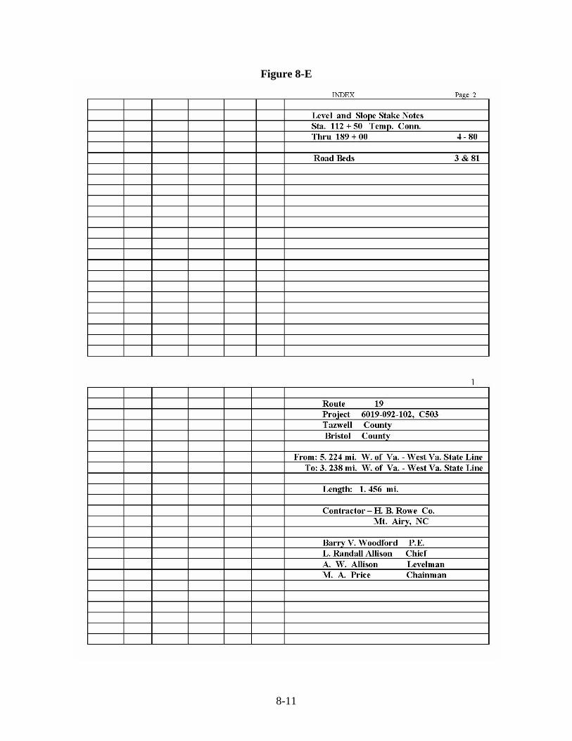
Figure 8-E

8-12
Figure 8-F

8-13
Figure 8-G

8-14
Figure 8-H
8-15
Figure 8-I

8-16
Figure 8-J

8-17
Figure 8-K

8-18
Figure 8-L Sketch Showing Procedure for Checking Box Culvert
Given:
Box Length (L) Box Height (H) Station and Finished Grade (A) Super Elevation (E) Flow Line Elevation (D) Pavement and Shoulder Width (R) Slope Rate (X) Delta (D)
Required: L1 and L2 Solution: Elevation “A” ± “E” = Elevation “B” Elevation Flow Line “D” + “H” = Elevation “C” “B” – “C” = “HI” “HI” x “X” = “S” “R” + “S” + “P” = L1 or L2 For Skew Angles: L1 or L2 = “R” + “S” + “P” Sin D

8-19
Sec. 8.17 SECTION 105.13 CONSTRUCTION STAKES, LINES, AND GRADES
105.13—State Force Construction Surveying.
(a) General Description:
This work shall consist of the Department performing all surveying and providing surveying and stakeout sketches and information as detailed herein for the successful prosecution of work as indicated on the plans and as directed by the Engineer. Stakeout work will be in accordance with the details and requirements of the Department’s Survey Manual and the provisions herein. Survey services will be provided to the extent detailed herein for Construction and for Minimum Plan projects.
(b) Request for Survey Services: Once the Contractor requests survey services, the Department will begin the requested work within 3 working days. The Contractor shall not expect the Department survey party to work in the field during adverse weather conditions that could be detrimental to the survey equipment or paperwork, therefore the Contractor shall plan the need for such services accordingly. It shall be the Contractor’s responsibility to preserve all Department furnished centerline or baseline controls, references and location benchmarks. After initial stakeout, an hourly charge equal to the current hourly rate for Department survey services per district will be billed to the Contractor for resetting stakes where the cause for the resetting of such stakes is due to the fault of the Contractor or his operations. This rate will also apply to travel time to and from the project. If the Contractor requests stakes after the initial staking and he is not ready to accommodate such work, the Contractor will be billed the hourly rate for Department survey services per district measured in travel time to and from the project. Such fees will be billed to the Contractor on the next monthly estimate.
(c) Contractor Responsibility for Examination of Data:
It shall be the responsibility of the Contractor to examine all surveying work provided by the Department for accuracy. Should a disagreement involving the accuracy of stakeout or survey work arise during construction, the Contractor shall within 24 hours provide written notice to the Engineer, precisely describing and documenting the discrepancy. The Engineer will determine the validity of the Contractor’s assertion in the notice, respond to the Contractor within 3 working days of receipt of the Contractor’s notice and provide direction on how to proceed. The Engineer will give consideration to an extension of time in accordance with the requirements of Section 108.04 of the Specifications or provide additional compensation as deemed appropriate after documentation and evidence to the Engineer’s satisfaction if the following occurs:

8-20
1. There are delays to the project as a result of inaccurate stakeout information provided
by the Department where such delays adversely impact the critical path of the work or,
2. where extra expense is encountered by the Contractor to correct elements of defective
survey work by the Department, and 3. where written notice is provided by the Contractor within the timeframe specified.
Failure to furnish written notice of such a discrepancy within the timeframe specified will invalidate any later claim for time impact or costs by the Contractor unless specifically waived by the Engineer.
(d) Survey Services Furnished:
1. Construction (C) Projects:
a. Survey Stakeout Descriptions:
Unless otherwise stated the Department will provide required horizontal and vertical controls for the proper construction stakeout of the project. The Contractor shall preserve all horizontal and vertical controls furnished by the Department.
The following surveying work will be performed by the Department: (1) Digital Terrain Model (DTM) and Construction Cross-Sections: Original
location Digital Terrain Model (DTMs) will be provided by the Department and will serve as a basis of payment for earthwork. The Contractor shall be responsible for taking construction DTMs or cross-sections of areas that, in their determination, do not agree with the Department furnished original location DTMs. The Contractor shall submit the disputed DTM information to the Engineer for verification prior to any excavation by the Contractor in these alleged areas of change. The DTM information furnished by the Department and submitted by the Contractor shall be compatible to the Department’s current DTM format.
(2) Borrow Pits: All borrow pit DTM’s or cross-sections, originals and finals,
will be secured by the Department. The Contractor is encouraged to also secure DTM’s or cross-sections of borrow areas. A claim of discrepancy in borrow volume will not be considered by the Engineer unless survey data was obtained and submitted by the Contractor to substantiate his claim.
(3) Horizontal and Vertical Control for Bridges: Certified plats, field notes,
coordinates and computations will be furnished to the Contractor by the

8-21
Department prior to the Contractor beginning work on these structures. (4) Horizontal and Vertical Controls for all Box Culverts, all Pipe Culvert
Installations (including single and multiple line installations) with total hydraulic openings equivalent to 12.6 square feet and larger, and for all closed systems such as storm sewers, and sanitary sewers regardless of size: The Department will stake all such installations. Certified Plats will be furnished to the Contractor prior to the Contractor beginning work on these culvert structures. The notes, coordinates, or computations used to support the platted information will be furnished to the Contractor with the certified plat. For the purposes of identifying those pipe culvert installations please refer to the areas (hydraulic openings) shown in the PB-1 Standards for the respective sizes of pipes specified on the plans. Where multiple lines of pipes are shown, the areas of the pipe sizes will apply to the total areas of the number of lines specified in the plans. For box culverts refer to the sizes shown in the BC-1 Standards to determine areas of total hydraulic opening.
(5) Horizontal and Vertical Control for Pipe Culvert Installations (including
single and multiple line installations) having total hydraulic openings equivalent to 3.1 square feet and up to 12.5 square feet: The Department will be responsible for staking horizontal and vertical control for pipe culvert installations having a total hydraulic opening equivalent to 3.1 square feet and up to 12.5 square feet. Sketches will be furnished to the Contractor prior to the Contractor beginning work on these culvert structures. For the purposes of identifying those pipe culvert installations please refer to the areas (hydraulic openings) shown in the PB-1 Standards for the respective sizes of pipes specified on the plans. Where multiple lines of pipes are shown, the areas of the pipe sizes shall apply to the total areas of the number of lines specified in the plans. For box culverts refer to the sizes shown in the BC-1 Standards to determine areas of total hydraulic opening.
(6) Horizontal and Vertical Control for additional centerlines or baselines
for roadways, ramps, loops and connections: Upon written request from the Contractor the Department will provide horizontal and vertical controls for additional centerlines or baselines for roadways, ramps, loops and connections.
(7) Grading and paving construction: The Department will provide fine grade
or other grade stakes required for the construction of the project as the work progresses except as stated herein. Fine grade stakes will be set on all projects on which the plans show a definite grade line. Fine grade hubs will be set on at least one side with distances and grades referenced to the finished centerline grade. Typically, on curves, the Department will provide the distances and elevations to each edge of pavement and centerline through the transitions and the distances and

8-22
elevations to the edge of pavement only (straight-line super) through full super portions of the curve. On projects where grading and paving is performed under the same contract, only one set of fine grade stakes will be provided to the Contractor. Fine grade stakes may be used for fine grade and paving grade.
On Secondary Road projects, fine grade stakes will be provided by the Department only on those projects having curb and gutter or as directed by the Engineer. Special design ditches will be staked with an offset and cut to the centerline of the ditch. Radius points for pavement flares at connections will be staked only if requested by the Contractor. The Department will set all slope stakes. Upon written request from the Contractor cut\fill sheets for slope stakes will be furnished by the Department to the Contractor within 3 working days of the survey party’s arrival at the project site or a timeframe agreed upon by the Contractor and the Engineer after reviewing the length and complexity of the project.
(8) Right of way and boundary stakeout affecting property ownership: Right of Way will be staked by the Department prior to the start of the project. Right of way stakes will be placed at a minimum of 100-foot intervals on each side of the roadway or as directed by the Engineer and the stakes will be marked with both the station and offset back to centerline. All final boundary stakeout will be performed by the Department’s survey party.
(9) Setting right-of-way monuments: Final right of way monumentation will be performed by the Department in accordance with the following:
a) RM-1: The Department will furnish and install RM-1 right-of-way
monuments in accordance with the Road and Bridge Standards. b) RM-2: The Department will furnish and install RM-2 right-of-way
monuments and optional locator posts, including the required caps, in accordance with the Road and Bridge Standards.
c) Other monumentation: The Department will determine if an alternative
form of permanent monumentation will be used if RM-1 or RM-2 monuments are unsuitable for marking the right-of-way at various locations. The Department will indicate this alternative monument usage on the final as-built plan in accordance with the Department’s Survey Manual.
8-23
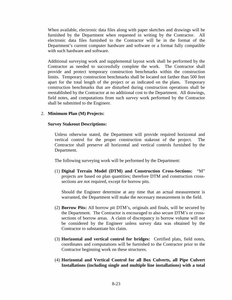
When available, electronic data files along with paper sketches and drawings will be furnished by the Department when requested in writing by the Contractor. All electronic data files furnished to the Contractor will be in the format of the Department’s current computer hardware and software or a format fully compatible with such hardware and software.
Additional surveying work and supplemental layout work shall be performed by the Contractor as needed to successfully complete the work. The Contractor shall provide and protect temporary construction benchmarks within the construction limits. Temporary construction benchmarks shall be located not farther than 500 feet apart for the total length of the project or as indicated on the plans. Temporary construction benchmarks that are disturbed during construction operations shall be reestablished by the Contractor at no additional cost to the Department. All drawings, field notes, and computations from such survey work performed by the Contractor shall be submitted to the Engineer.
2. Minimum Plan (M) Projects:
Survey Stakeout Descriptions:
Unless otherwise stated, the Department will provide required horizontal and vertical control for the proper construction stakeout of the project. The Contractor shall preserve all horizontal and vertical controls furnished by the Department.
The following surveying work will be performed by the Department:
(1) Digital Terrain Model (DTM) and Construction Cross-Sections: “M”
projects are based on plan quantities; therefore DTM and construction cross-sections are not required, except for borrow pits.
Should the Engineer determine at any time that an actual measurement is warranted, the Department will make the necessary measurement in the field.
(2) Borrow Pits: All borrow pit DTM’s, originals and finals, will be secured by
the Department. The Contractor is encouraged to also secure DTM’s or cross-sections of borrow areas. A claim of discrepancy in borrow volume will not be considered by the Engineer unless survey data was obtained by the Contractor to substantiate his claim.
(3) Horizontal and vertical control for bridges: Certified plats, field notes,
coordinates and computations will be furnished to the Contractor prior to the Contractor beginning work on these structures.
(4) Horizontal and Vertical Control for all Box Culverts, all Pipe Culvert
Installations (including single and multiple line installations) with a total

8-24
hydraulic openings equivalent to 12.6 square feet and larger, and for all closed systems such as storm sewers, and sanitary sewers regardless of size: The Department will stake all such installations. Certified Plats for these stakeouts will be furnished to the Contractor prior to the Contractor beginning work on these culvert structures. The notes, or computations used to support the platted information will be furnished to the Contractor with the certified plat. For the purposes of identifying those pipe culvert installations please refer to the areas (hydraulic openings) shown in the PB-1 Standards for the respective sizes of pipes specified on the plans. Where multiple lines of pipes are shown, the areas of the pipe sizes will apply to the total areas of the number of lines specified in the plans. For box culverts refer to the sizes shown in the BC-1 Standards to determine areas of total hydraulic openings.
(5) Horizontal and Verticals Control for Pipe Culvert installations (including
single and multiple line installations) having total hydraulic openings equivalent to 3.1 square feet and up to 12.5 square feet: The Department will be responsible for staking horizontal and vertical controls for pipe culvert installations having a total hydraulic opening equivalent to 3.1 square feet and up to 12.5 square feet. Sketches will be furnished to the Contractor prior to the Contractor beginning work on these culvert structures. For the purposes of identifying those pipe culvert installations please refer to the areas (hydraulic openings) shown in the PB-1 Standards for the respective sizes of pipes specified on the plans. Where multiple lines of pipes are shown, the areas of the pipe sizes will apply to the total areas of the number of lines specified in the plans. For box culverts refer to the sizes shown in the BC-1 Standards to determine areas of total hydraulic opening.
(6) Grading and paving construction: The Department will provide fine grade
or other grade stakes required for the construction of all projects except as stated herein as the work progresses. Slope stakes are not required on “M” projects. Fine grade stakes will be set on all projects on which the plans show a definite grade line. Fine grade hubs will be set on at least one side with distances and grades referenced to the finished centerline grade. Typically, on curves, the Department will provide the distances and elevations to each edge of pavement and centerline through the transitions and the distances and elevations to the edge of pavement only (straight-line super) through full super portions of the curve. On projects where grading and paving is performed under the same contract, only one set of fine grade stakes will be provided by the Department.. Fine grade stakes may be used for fine grade and paving grade.

8-25
On Secondary Road projects, fine grade stakes will be provided by the Department only on those projects having curb and gutter or as directed by the Engineer. Special design ditches will be staked with an offset and cut to the centerline of the ditch. Radius points for pavement flares at connections will be staked only if requested by the Contractor.
(7) Right of way and boundary stakeout affecting property ownership: Right of Way will be staked by the Department prior to the start of the job. The right of way stakes will be placed at a minimum of 100-foot intervals on each side of the roadway or as directed by the Engineer and the stakes will be marked with both the station and offset back to centerline. All final boundary stakeout will be performed by the Department survey party.
(8) Setting right-of-way monuments: Final right of way monumentation will be
performed by the Department in accordance with the following:
a) RM-1: The Department will furnish and install RM-1 right-of-way monuments in accordance with the Road and Bridge Standards.
b) RM-2: The Department will furnish and install RM-2 right-of-way
monuments and optional locator posts, including the required caps, in accordance with the Road and Bridge Standards.
c) Other monumentation: The Department will determine if an alternative
form of permanent monumentation will be used if RM-1 or RM-2 monuments are unsuitable for marking the right-of-way at various locations. The Department will indicate this alternative monument usage on the final as-built plan in accordance with the Department’s Survey Manual.

8-26
8-27

8-28

8-29

8-30

8-31

8-32

8-33
8-34

8-35

8-36