1 CHAPTER 8 Molecular Structure & Covalent Bonding Theories.

Chapter 8
Advanced Theories of CovalentBonding
Figure 8.1 Oxygen molecules orient randomly most of the time, as shown in the top magnified view. However, whenwe pour liquid oxygen through a magnet, the molecules line up with the magnetic field, and the attraction allows themto stay suspended between the poles of the magnet where the magnetic field is strongest. Other diatomic molecules(like N2) flow past the magnet. The detailed explanation of bonding described in this chapter allows us to understandthis phenomenon. (credit: modification of work by Jefferson Lab)
Chapter Outline
8.1 Valence Bond Theory
8.2 Hybrid Atomic Orbitals
8.3 Multiple Bonds
8.4 Molecular Orbital Theory
IntroductionWe have examined the basic ideas of bonding, showing that atoms share electrons to form molecules with stableLewis structures and that we can predict the shapes of those molecules by valence shell electron pair repulsion(VSEPR) theory. These ideas provide an important starting point for understanding chemical bonding. But thesemodels sometimes fall short in their abilities to predict the behavior of real substances. How can we reconcile thegeometries of s, p, and d atomic orbitals with molecular shapes that show angles like 120° and 109.5°? Furthermore,we know that electrons and magnetic behavior are related through electromagnetic fields. Both N2 and O2 have fairlysimilar Lewis structures that contain lone pairs of electrons.
Yet oxygen demonstrates very different magnetic behavior than nitrogen. We can pour liquid nitrogen through amagnetic field with no visible interactions, while liquid oxygen (shown in Figure 8.1) is attracted to the magnetand floats in the magnetic field. We need to understand the additional concepts of valence bond theory, orbital
Chapter 8 | Advanced Theories of Covalent Bonding 411
hybridization, and molecular orbital theory to understand these observations.
8.1 Valence Bond Theory
By the end of this section, you will be able to:
• Describe the formation of covalent bonds in terms of atomic orbital overlap
• Define and give examples of σ and π bonds
As we know, a scientific theory is a strongly supported explanation for observed natural laws or large bodies ofexperimental data. For a theory to be accepted, it must explain experimental data and be able to predict behavior. Forexample, VSEPR theory has gained widespread acceptance because it predicts three-dimensional molecular shapesthat are consistent with experimental data collected for thousands of different molecules. However, VSEPR theorydoes not provide an explanation of chemical bonding.
There are successful theories that describe the electronic structure of atoms. We can use quantum mechanics to predictthe specific regions around an atom where electrons are likely to be located: A spherical shape for an s orbital, adumbbell shape for a p orbital, and so forth. However, these predictions only describe the orbitals around free atoms.When atoms bond to form molecules, atomic orbitals are not sufficient to describe the regions where electrons will belocated in the molecule. A more complete understanding of electron distributions requires a model that can accountfor the electronic structure of molecules. One popular theory holds that a covalent bond forms when a pair of electronsis shared by two atoms and is simultaneously attracted by the nuclei of both atoms. In the following sections, we willdiscuss how such bonds are described by valence bond theory and hybridization.
Valence bond theory describes a covalent bond as the overlap of half-filled atomic orbitals (each containing a singleelectron) that yield a pair of electrons shared between the two bonded atoms. We say that orbitals on two differentatoms overlap when a portion of one orbital and a portion of a second orbital occupy the same region of space.According to valence bond theory, a covalent bond results when two conditions are met: (1) an orbital on one atomoverlaps an orbital on a second atom and (2) the single electrons in each orbital combine to form an electron pair. Themutual attraction between this negatively charged electron pair and the two atoms’ positively charged nuclei serves tophysically link the two atoms through a force we define as a covalent bond. The strength of a covalent bond dependson the extent of overlap of the orbitals involved. Orbitals that overlap extensively form bonds that are stronger thanthose that have less overlap.
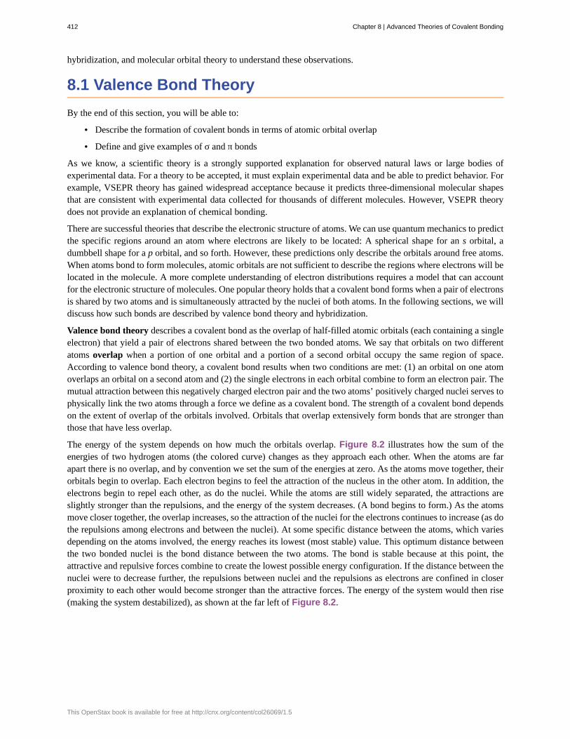
The energy of the system depends on how much the orbitals overlap. Figure 8.2 illustrates how the sum of theenergies of two hydrogen atoms (the colored curve) changes as they approach each other. When the atoms are farapart there is no overlap, and by convention we set the sum of the energies at zero. As the atoms move together, theirorbitals begin to overlap. Each electron begins to feel the attraction of the nucleus in the other atom. In addition, theelectrons begin to repel each other, as do the nuclei. While the atoms are still widely separated, the attractions areslightly stronger than the repulsions, and the energy of the system decreases. (A bond begins to form.) As the atomsmove closer together, the overlap increases, so the attraction of the nuclei for the electrons continues to increase (as dothe repulsions among electrons and between the nuclei). At some specific distance between the atoms, which variesdepending on the atoms involved, the energy reaches its lowest (most stable) value. This optimum distance betweenthe two bonded nuclei is the bond distance between the two atoms. The bond is stable because at this point, theattractive and repulsive forces combine to create the lowest possible energy configuration. If the distance between thenuclei were to decrease further, the repulsions between nuclei and the repulsions as electrons are confined in closerproximity to each other would become stronger than the attractive forces. The energy of the system would then rise(making the system destabilized), as shown at the far left of Figure 8.2.
412 Chapter 8 | Advanced Theories of Covalent Bonding
This OpenStax book is available for free at http://cnx.org/content/col26069/1.5
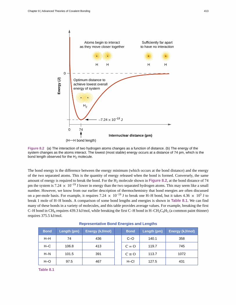
Figure 8.2 (a) The interaction of two hydrogen atoms changes as a function of distance. (b) The energy of thesystem changes as the atoms interact. The lowest (most stable) energy occurs at a distance of 74 pm, which is thebond length observed for the H2 molecule.
The bond energy is the difference between the energy minimum (which occurs at the bond distance) and the energyof the two separated atoms. This is the quantity of energy released when the bond is formed. Conversely, the sameamount of energy is required to break the bond. For the H2 molecule shown in Figure 8.2, at the bond distance of 74pm the system is 7.24 × 10⁻¹⁹ J lower in energy than the two separated hydrogen atoms. This may seem like a smallnumber. However, we know from our earlier description of thermochemistry that bond energies are often discussedon a per-mole basis. For example, it requires 7.24 × 10⁻¹⁹ J to break one H–H bond, but it takes 4.36 × 10⁵ J tobreak 1 mole of H–H bonds. A comparison of some bond lengths and energies is shown in Table 8.1. We can findmany of these bonds in a variety of molecules, and this table provides average values. For example, breaking the firstC–H bond in CH4 requires 439.3 kJ/mol, while breaking the first C–H bond in H–CH2C6H5 (a common paint thinner)requires 375.5 kJ/mol.
Representative Bond Energies and Lengths
Bond Length (pm) Energy (kJ/mol) Bond Length (pm) Energy (kJ/mol)
H–H 74 436 C–O 140.1 358
H–C 106.8 413 C = O 119.7 745
H–N 101.5 391 C ≡ O 113.7 1072
H–O 97.5 467 H–Cl 127.5 431
Table 8.1
Chapter 8 | Advanced Theories of Covalent Bonding 413
Representative Bond Energies and Lengths
Bond Length (pm) Energy (kJ/mol) Bond Length (pm) Energy (kJ/mol)
C–C 150.6 347 H–Br 141.4 366
C = C 133.5 614 H–I 160.9 298
C ≡ C 120.8 839 O–O 148 146
C–N 142.1 305 O = O 120.8 498
C = N 130.0 615 F–F 141.2 159
C ≡ N 116.1 891 Cl–Cl 198.8 243
Table 8.1
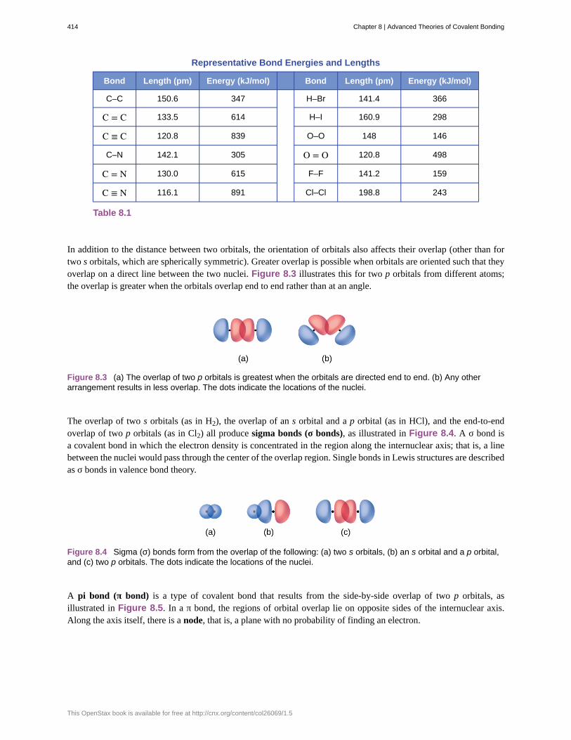
In addition to the distance between two orbitals, the orientation of orbitals also affects their overlap (other than fortwo s orbitals, which are spherically symmetric). Greater overlap is possible when orbitals are oriented such that theyoverlap on a direct line between the two nuclei. Figure 8.3 illustrates this for two p orbitals from different atoms;the overlap is greater when the orbitals overlap end to end rather than at an angle.
Figure 8.3 (a) The overlap of two p orbitals is greatest when the orbitals are directed end to end. (b) Any otherarrangement results in less overlap. The dots indicate the locations of the nuclei.
The overlap of two s orbitals (as in H2), the overlap of an s orbital and a p orbital (as in HCl), and the end-to-endoverlap of two p orbitals (as in Cl2) all produce sigma bonds (σ bonds), as illustrated in Figure 8.4. A σ bond isa covalent bond in which the electron density is concentrated in the region along the internuclear axis; that is, a linebetween the nuclei would pass through the center of the overlap region. Single bonds in Lewis structures are describedas σ bonds in valence bond theory.
Figure 8.4 Sigma (σ) bonds form from the overlap of the following: (a) two s orbitals, (b) an s orbital and a p orbital,and (c) two p orbitals. The dots indicate the locations of the nuclei.
A pi bond (π bond) is a type of covalent bond that results from the side-by-side overlap of two p orbitals, asillustrated in Figure 8.5. In a π bond, the regions of orbital overlap lie on opposite sides of the internuclear axis.Along the axis itself, there is a node, that is, a plane with no probability of finding an electron.
414 Chapter 8 | Advanced Theories of Covalent Bonding
This OpenStax book is available for free at http://cnx.org/content/col26069/1.5
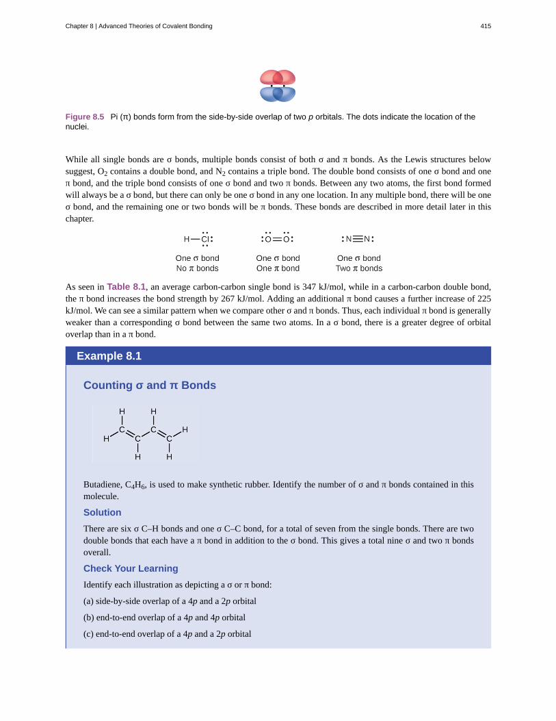
Figure 8.5 Pi (π) bonds form from the side-by-side overlap of two p orbitals. The dots indicate the location of thenuclei.
While all single bonds are σ bonds, multiple bonds consist of both σ and π bonds. As the Lewis structures belowsuggest, O2 contains a double bond, and N2 contains a triple bond. The double bond consists of one σ bond and oneπ bond, and the triple bond consists of one σ bond and two π bonds. Between any two atoms, the first bond formedwill always be a σ bond, but there can only be one σ bond in any one location. In any multiple bond, there will be oneσ bond, and the remaining one or two bonds will be π bonds. These bonds are described in more detail later in thischapter.
As seen in Table 8.1, an average carbon-carbon single bond is 347 kJ/mol, while in a carbon-carbon double bond,the π bond increases the bond strength by 267 kJ/mol. Adding an additional π bond causes a further increase of 225kJ/mol. We can see a similar pattern when we compare other σ and π bonds. Thus, each individual π bond is generallyweaker than a corresponding σ bond between the same two atoms. In a σ bond, there is a greater degree of orbitaloverlap than in a π bond.
Example 8.1
Counting σ and π Bonds
Butadiene, C4H6, is used to make synthetic rubber. Identify the number of σ and π bonds contained in thismolecule.
Solution
There are six σ C–H bonds and one σ C–C bond, for a total of seven from the single bonds. There are twodouble bonds that each have a π bond in addition to the σ bond. This gives a total nine σ and two π bondsoverall.
Check Your Learning
Identify each illustration as depicting a σ or π bond:
(a) side-by-side overlap of a 4p and a 2p orbital
(b) end-to-end overlap of a 4p and 4p orbital
(c) end-to-end overlap of a 4p and a 2p orbital
Chapter 8 | Advanced Theories of Covalent Bonding 415

Answer: (a) is a π bond with a node along the axis connecting the nuclei while (b) and (c) are σ bonds thatoverlap along the axis.
8.2 Hybrid Atomic Orbitals
By the end of this section, you will be able to:
• Explain the concept of atomic orbital hybridization
• Determine the hybrid orbitals associated with various molecular geometries
Thinking in terms of overlapping atomic orbitals is one way for us to explain how chemical bonds form in diatomicmolecules. However, to understand how molecules with more than two atoms form stable bonds, we require a moredetailed model. As an example, let us consider the water molecule, in which we have one oxygen atom bonding totwo hydrogen atoms. Oxygen has the electron configuration 1s22s22p4, with two unpaired electrons (one in each ofthe two 2p orbitals). Valence bond theory would predict that the two O–H bonds form from the overlap of these two2p orbitals with the 1s orbitals of the hydrogen atoms. If this were the case, the bond angle would be 90°, as shownin Figure 8.6, because p orbitals are perpendicular to each other. Experimental evidence shows that the bond angleis 104.5°, not 90°. The prediction of the valence bond theory model does not match the real-world observations of awater molecule; a different model is needed.
Figure 8.6 The hypothetical overlap of two of the 2p orbitals on an oxygen atom (red) with the 1s orbitals of twohydrogen atoms (blue) would produce a bond angle of 90°. This is not consistent with experimental evidence.[1]
Quantum-mechanical calculations suggest why the observed bond angles in H2O differ from those predicted bythe overlap of the 1s orbital of the hydrogen atoms with the 2p orbitals of the oxygen atom. The mathematicalexpression known as the wave function, ψ, contains information about each orbital and the wavelike properties ofelectrons in an isolated atom. When atoms are bound together in a molecule, the wave functions combine to producenew mathematical descriptions that have different shapes. This process of combining the wave functions for atomicorbitals is called hybridization and is mathematically accomplished by the linear combination of atomic orbitals,LCAO, (a technique that we will encounter again later). The new orbitals that result are called hybrid orbitals.The valence orbitals in an isolated oxygen atom are a 2s orbital and three 2p orbitals. The valence orbitals in anoxygen atom in a water molecule differ; they consist of four equivalent hybrid orbitals that point approximatelytoward the corners of a tetrahedron (Figure 8.7). Consequently, the overlap of the O and H orbitals should resultin a tetrahedral bond angle (109.5°). The observed angle of 104.5° is experimental evidence for which quantum-mechanical calculations give a useful explanation: Valence bond theory must include a hybridization component togive accurate predictions.
1. Note that orbitals may sometimes be drawn in an elongated “balloon” shape rather than in a more realistic “plump” shape in order tomake the geometry easier to visualize.
416 Chapter 8 | Advanced Theories of Covalent Bonding
This OpenStax book is available for free at http://cnx.org/content/col26069/1.5

Figure 8.7 (a) A water molecule has four regions of electron density, so VSEPR theory predicts a tetrahedralarrangement of hybrid orbitals. (b) Two of the hybrid orbitals on oxygen contain lone pairs, and the other two overlapwith the 1s orbitals of hydrogen atoms to form the O–H bonds in H2O. This description is more consistent with theexperimental structure.
The following ideas are important in understanding hybridization:
1. Hybrid orbitals do not exist in isolated atoms. They are formed only in covalently bonded atoms.
2. Hybrid orbitals have shapes and orientations that are very different from those of the atomic orbitals in isolatedatoms.
3. A set of hybrid orbitals is generated by combining atomic orbitals. The number of hybrid orbitals in a set isequal to the number of atomic orbitals that were combined to produce the set.
4. All orbitals in a set of hybrid orbitals are equivalent in shape and energy.
5. The type of hybrid orbitals formed in a bonded atom depends on its electron-pair geometry as predicted by theVSEPR theory.
6. Hybrid orbitals overlap to form σ bonds. Unhybridized orbitals overlap to form π bonds.
In the following sections, we shall discuss the common types of hybrid orbitals.
sp Hybridization
The beryllium atom in a gaseous BeCl2 molecule is an example of a central atom with no lone pairs of electrons ina linear arrangement of three atoms. There are two regions of valence electron density in the BeCl2 molecule thatcorrespond to the two covalent Be–Cl bonds. To accommodate these two electron domains, two of the Be atom’sfour valence orbitals will mix to yield two hybrid orbitals. This hybridization process involves mixing of the valences orbital with one of the valence p orbitals to yield two equivalent sp hybrid orbitals that are oriented in a lineargeometry (Figure 8.8). In this figure, the set of sp orbitals appears similar in shape to the original p orbital, butthere is an important difference. The number of atomic orbitals combined always equals the number of hybrid orbitalsformed. The p orbital is one orbital that can hold up to two electrons. The sp set is two equivalent orbitals that point180° from each other. The two electrons that were originally in the s orbital are now distributed to the two sp orbitals,which are half filled. In gaseous BeCl2, these half-filled hybrid orbitals will overlap with orbitals from the chlorineatoms to form two identical σ bonds.
Chapter 8 | Advanced Theories of Covalent Bonding 417
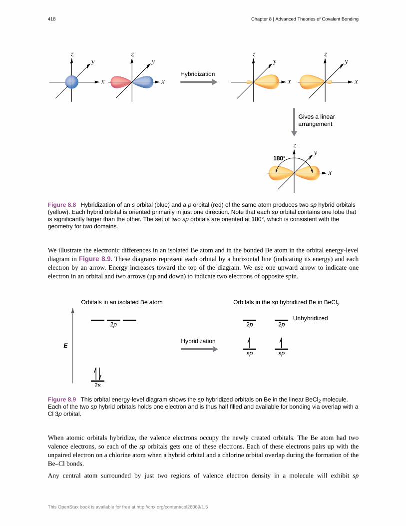
Figure 8.8 Hybridization of an s orbital (blue) and a p orbital (red) of the same atom produces two sp hybrid orbitals(yellow). Each hybrid orbital is oriented primarily in just one direction. Note that each sp orbital contains one lobe thatis significantly larger than the other. The set of two sp orbitals are oriented at 180°, which is consistent with thegeometry for two domains.
We illustrate the electronic differences in an isolated Be atom and in the bonded Be atom in the orbital energy-leveldiagram in Figure 8.9. These diagrams represent each orbital by a horizontal line (indicating its energy) and eachelectron by an arrow. Energy increases toward the top of the diagram. We use one upward arrow to indicate oneelectron in an orbital and two arrows (up and down) to indicate two electrons of opposite spin.
Figure 8.9 This orbital energy-level diagram shows the sp hybridized orbitals on Be in the linear BeCl2 molecule.Each of the two sp hybrid orbitals holds one electron and is thus half filled and available for bonding via overlap with aCl 3p orbital.
When atomic orbitals hybridize, the valence electrons occupy the newly created orbitals. The Be atom had twovalence electrons, so each of the sp orbitals gets one of these electrons. Each of these electrons pairs up with theunpaired electron on a chlorine atom when a hybrid orbital and a chlorine orbital overlap during the formation of theBe–Cl bonds.
Any central atom surrounded by just two regions of valence electron density in a molecule will exhibit sp
418 Chapter 8 | Advanced Theories of Covalent Bonding
This OpenStax book is available for free at http://cnx.org/content/col26069/1.5

hybridization. Other examples include the mercury atom in the linear HgCl2 molecule, the zinc atom in Zn(CH3)2,which contains a linear C–Zn–C arrangement, and the carbon atoms in HCCH and CO2.
Check out the University of Wisconsin-Oshkosh website (http://openstaxcollege.org/l/16hybridorbital)to learn about visualizing hybrid orbitals in three dimensions.
sp2 Hybridization
The valence orbitals of a central atom surrounded by three regions of electron density consist of a set of three sp2
hybrid orbitals and one unhybridized p orbital. This arrangement results from sp2 hybridization, the mixing of ones orbital and two p orbitals to produce three identical hybrid orbitals oriented in a trigonal planar geometry (Figure8.10).
Figure 8.10 The hybridization of an s orbital (blue) and two p orbitals (red) produces three equivalent sp2 hybridizedorbitals (yellow) oriented at 120° with respect to each other. The remaining unhybridized p orbital is not shown here,but is located along the z axis.
Although quantum mechanics yields the “plump” orbital lobes as depicted in Figure 8.10, sometimes for claritythese orbitals are drawn thinner and without the minor lobes, as in Figure 8.11, to avoid obscuring other featuresof a given illustration. We will use these “thinner” representations whenever the true view is too crowded to easilyvisualize.
Link to Learning
Chapter 8 | Advanced Theories of Covalent Bonding 419

Figure 8.11 This alternate way of drawing the trigonal planar sp2 hybrid orbitals is sometimes used in more crowdedfigures.
The observed structure of the borane molecule, BH3, suggests sp2 hybridization for boron in this compound. Themolecule is trigonal planar, and the boron atom is involved in three bonds to hydrogen atoms (Figure 8.12). We canillustrate the comparison of orbitals and electron distribution in an isolated boron atom and in the bonded atom inBH3 as shown in the orbital energy level diagram in Figure 8.13. We redistribute the three valence electrons of theboron atom in the three sp2 hybrid orbitals, and each boron electron pairs with a hydrogen electron when B–H bondsform.
Figure 8.12 BH3 is an electron-deficient molecule with a trigonal planar structure.
Figure 8.13 In an isolated B atom, there are one 2s and three 2p valence orbitals. When boron is in a molecule withthree regions of electron density, three of the orbitals hybridize and create a set of three sp2 orbitals and oneunhybridized 2p orbital. The three half-filled hybrid orbitals each overlap with an orbital from a hydrogen atom to formthree σ bonds in BH3.
Any central atom surrounded by three regions of electron density will exhibit sp2 hybridization. This includesmolecules with a lone pair on the central atom, such as ClNO (Figure 8.14), or molecules with two single bonds anda double bond connected to the central atom, as in formaldehyde, CH2O, and ethene, H2CCH2.
420 Chapter 8 | Advanced Theories of Covalent Bonding
This OpenStax book is available for free at http://cnx.org/content/col26069/1.5

Figure 8.14 The central atom(s) in each of the structures shown contain three regions of electron density and aresp2 hybridized. As we know from the discussion of VSEPR theory, a region of electron density contains all of theelectrons that point in one direction. A lone pair, an unpaired electron, a single bond, or a multiple bond would eachcount as one region of electron density.
sp3 Hybridization
The valence orbitals of an atom surrounded by a tetrahedral arrangement of bonding pairs and lone pairs consist ofa set of four sp3 hybrid orbitals. The hybrids result from the mixing of one s orbital and all three p orbitals thatproduces four identical sp3 hybrid orbitals (Figure 8.15). Each of these hybrid orbitals points toward a differentcorner of a tetrahedron.
Chapter 8 | Advanced Theories of Covalent Bonding 421
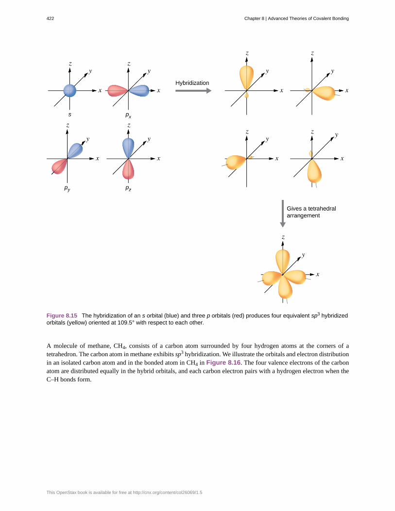
Figure 8.15 The hybridization of an s orbital (blue) and three p orbitals (red) produces four equivalent sp3 hybridizedorbitals (yellow) oriented at 109.5° with respect to each other.
A molecule of methane, CH4, consists of a carbon atom surrounded by four hydrogen atoms at the corners of atetrahedron. The carbon atom in methane exhibits sp3 hybridization. We illustrate the orbitals and electron distributionin an isolated carbon atom and in the bonded atom in CH4 in Figure 8.16. The four valence electrons of the carbonatom are distributed equally in the hybrid orbitals, and each carbon electron pairs with a hydrogen electron when theC–H bonds form.
422 Chapter 8 | Advanced Theories of Covalent Bonding
This OpenStax book is available for free at http://cnx.org/content/col26069/1.5
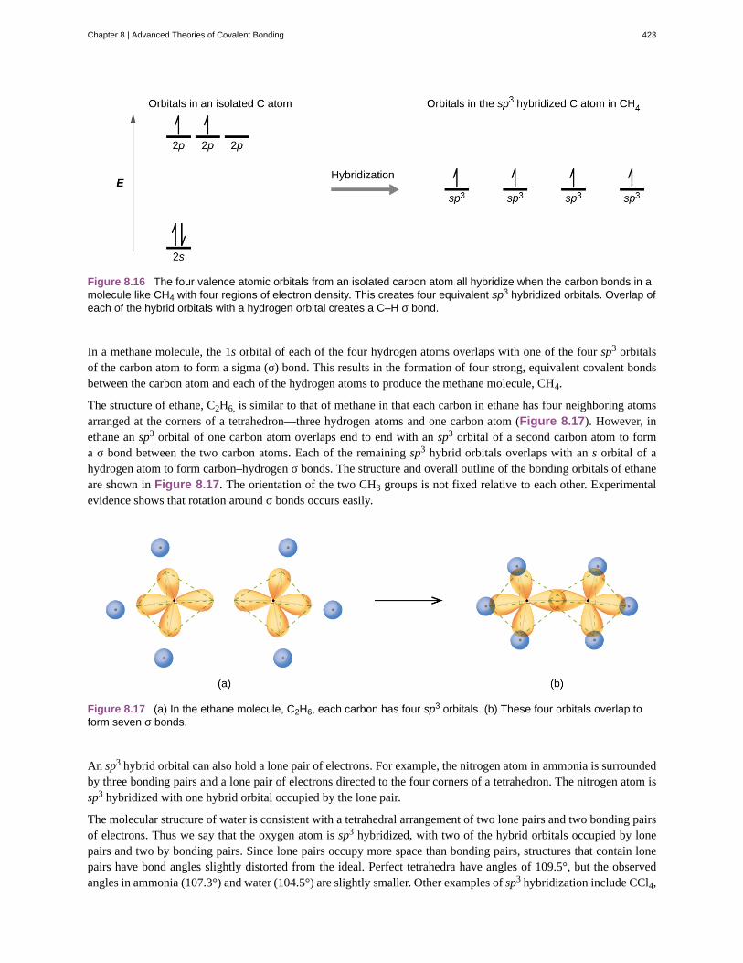
Figure 8.16 The four valence atomic orbitals from an isolated carbon atom all hybridize when the carbon bonds in amolecule like CH4 with four regions of electron density. This creates four equivalent sp3 hybridized orbitals. Overlap ofeach of the hybrid orbitals with a hydrogen orbital creates a C–H σ bond.
In a methane molecule, the 1s orbital of each of the four hydrogen atoms overlaps with one of the four sp3 orbitalsof the carbon atom to form a sigma (σ) bond. This results in the formation of four strong, equivalent covalent bondsbetween the carbon atom and each of the hydrogen atoms to produce the methane molecule, CH4.
The structure of ethane, C2H6, is similar to that of methane in that each carbon in ethane has four neighboring atomsarranged at the corners of a tetrahedron—three hydrogen atoms and one carbon atom (Figure 8.17). However, inethane an sp3 orbital of one carbon atom overlaps end to end with an sp3 orbital of a second carbon atom to forma σ bond between the two carbon atoms. Each of the remaining sp3 hybrid orbitals overlaps with an s orbital of ahydrogen atom to form carbon–hydrogen σ bonds. The structure and overall outline of the bonding orbitals of ethaneare shown in Figure 8.17. The orientation of the two CH3 groups is not fixed relative to each other. Experimentalevidence shows that rotation around σ bonds occurs easily.
Figure 8.17 (a) In the ethane molecule, C2H6, each carbon has four sp3 orbitals. (b) These four orbitals overlap toform seven σ bonds.
An sp3 hybrid orbital can also hold a lone pair of electrons. For example, the nitrogen atom in ammonia is surroundedby three bonding pairs and a lone pair of electrons directed to the four corners of a tetrahedron. The nitrogen atom issp3 hybridized with one hybrid orbital occupied by the lone pair.
The molecular structure of water is consistent with a tetrahedral arrangement of two lone pairs and two bonding pairsof electrons. Thus we say that the oxygen atom is sp3 hybridized, with two of the hybrid orbitals occupied by lonepairs and two by bonding pairs. Since lone pairs occupy more space than bonding pairs, structures that contain lonepairs have bond angles slightly distorted from the ideal. Perfect tetrahedra have angles of 109.5°, but the observedangles in ammonia (107.3°) and water (104.5°) are slightly smaller. Other examples of sp3 hybridization include CCl4,
Chapter 8 | Advanced Theories of Covalent Bonding 423

PCl3, and NCl3.
sp3d and sp3d2 Hybridization
To describe the five bonding orbitals in a trigonal bipyramidal arrangement, we must use five of the valence shellatomic orbitals (the s orbital, the three p orbitals, and one of the d orbitals), which gives five sp3d hybrid orbitals.With an octahedral arrangement of six hybrid orbitals, we must use six valence shell atomic orbitals (the s orbital,the three p orbitals, and two of the d orbitals in its valence shell), which gives six sp3d2 hybrid orbitals. Thesehybridizations are only possible for atoms that have d orbitals in their valence subshells (that is, not those in the firstor second period).
In a molecule of phosphorus pentachloride, PCl5, there are five P–Cl bonds (thus five pairs of valence electronsaround the phosphorus atom) directed toward the corners of a trigonal bipyramid. We use the 3s orbital, the three 3porbitals, and one of the 3d orbitals to form the set of five sp3d hybrid orbitals (Figure 8.19) that are involved in theP–Cl bonds. Other atoms that exhibit sp3d hybridization include the sulfur atom in SF4 and the chlorine atoms in ClF3
and in ClF4+. (The electrons on fluorine atoms are omitted for clarity.)
Figure 8.18 The three compounds pictured exhibit sp3d hybridization in the central atom and a trigonal bipyramidform. SF4 and ClF4
+ have one lone pair of electrons on the central atom, and ClF3 has two lone pairs giving it the
T-shape shown.
Figure 8.19 (a) The five regions of electron density around phosphorus in PCl5 require five hybrid sp3d orbitals. (b)These orbitals combine to form a trigonal bipyramidal structure with each large lobe of the hybrid orbital pointing at avertex. As before, there are also small lobes pointing in the opposite direction for each orbital (not shown for clarity).
The sulfur atom in sulfur hexafluoride, SF6, exhibits sp3d2 hybridization. A molecule of sulfur hexafluoride has sixbonding pairs of electrons connecting six fluorine atoms to a single sulfur atom. There are no lone pairs of electronson the central atom. To bond six fluorine atoms, the 3s orbital, the three 3p orbitals, and two of the 3d orbitalsform six equivalent sp3d2 hybrid orbitals, each directed toward a different corner of an octahedron. Other atoms thatexhibit sp3d2 hybridization include the phosphorus atom in PCl6
−, the iodine atom in the interhalogens IF6+, IF5,
ICl4−, IF4
− and the xenon atom in XeF4.
424 Chapter 8 | Advanced Theories of Covalent Bonding
This OpenStax book is available for free at http://cnx.org/content/col26069/1.5
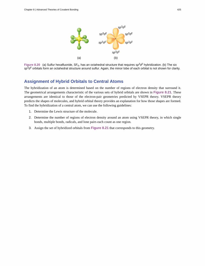
Figure 8.20 (a) Sulfur hexafluoride, SF6, has an octahedral structure that requires sp3d2 hybridization. (b) The sixsp3d2 orbitals form an octahedral structure around sulfur. Again, the minor lobe of each orbital is not shown for clarity.
Assignment of Hybrid Orbitals to Central Atoms
The hybridization of an atom is determined based on the number of regions of electron density that surround it.The geometrical arrangements characteristic of the various sets of hybrid orbitals are shown in Figure 8.21. Thesearrangements are identical to those of the electron-pair geometries predicted by VSEPR theory. VSEPR theorypredicts the shapes of molecules, and hybrid orbital theory provides an explanation for how those shapes are formed.To find the hybridization of a central atom, we can use the following guidelines:
1. Determine the Lewis structure of the molecule.
2. Determine the number of regions of electron density around an atom using VSEPR theory, in which singlebonds, multiple bonds, radicals, and lone pairs each count as one region.
3. Assign the set of hybridized orbitals from Figure 8.21 that corresponds to this geometry.
Chapter 8 | Advanced Theories of Covalent Bonding 425
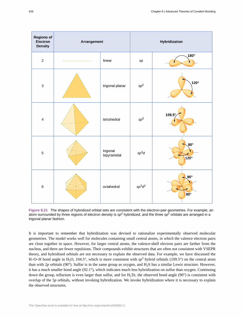
Figure 8.21 The shapes of hybridized orbital sets are consistent with the electron-pair geometries. For example, anatom surrounded by three regions of electron density is sp2 hybridized, and the three sp2 orbitals are arranged in atrigonal planar fashion.
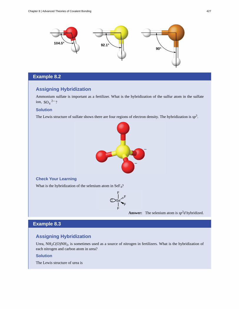
It is important to remember that hybridization was devised to rationalize experimentally observed moleculargeometries. The model works well for molecules containing small central atoms, in which the valence electron pairsare close together in space. However, for larger central atoms, the valence-shell electron pairs are farther from thenucleus, and there are fewer repulsions. Their compounds exhibit structures that are often not consistent with VSEPRtheory, and hybridized orbitals are not necessary to explain the observed data. For example, we have discussed theH–O–H bond angle in H2O, 104.5°, which is more consistent with sp3 hybrid orbitals (109.5°) on the central atomthan with 2p orbitals (90°). Sulfur is in the same group as oxygen, and H2S has a similar Lewis structure. However,it has a much smaller bond angle (92.1°), which indicates much less hybridization on sulfur than oxygen. Continuingdown the group, tellurium is even larger than sulfur, and for H2Te, the observed bond angle (90°) is consistent withoverlap of the 5p orbitals, without invoking hybridization. We invoke hybridization where it is necessary to explainthe observed structures.
426 Chapter 8 | Advanced Theories of Covalent Bonding
This OpenStax book is available for free at http://cnx.org/content/col26069/1.5
Example 8.2
Assigning Hybridization
Ammonium sulfate is important as a fertilizer. What is the hybridization of the sulfur atom in the sulfateion, SO4
2−?
Solution
The Lewis structure of sulfate shows there are four regions of electron density. The hybridization is sp3.
Check Your Learning
What is the hybridization of the selenium atom in SeF4?
Answer: The selenium atom is sp3d hybridized.
Example 8.3
Assigning Hybridization
Urea, NH2C(O)NH2, is sometimes used as a source of nitrogen in fertilizers. What is the hybridization ofeach nitrogen and carbon atom in urea?
Solution
The Lewis structure of urea is
Chapter 8 | Advanced Theories of Covalent Bonding 427
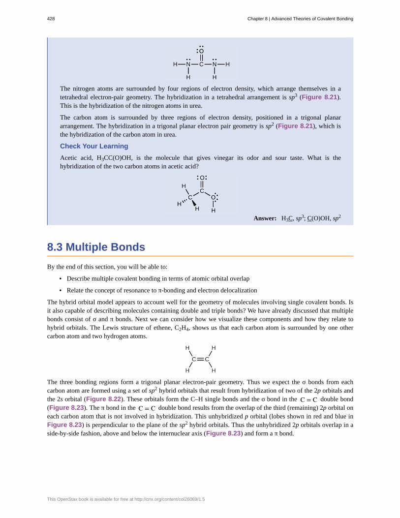
The nitrogen atoms are surrounded by four regions of electron density, which arrange themselves in atetrahedral electron-pair geometry. The hybridization in a tetrahedral arrangement is sp3 (Figure 8.21).This is the hybridization of the nitrogen atoms in urea.
The carbon atom is surrounded by three regions of electron density, positioned in a trigonal planararrangement. The hybridization in a trigonal planar electron pair geometry is sp2 (Figure 8.21), which isthe hybridization of the carbon atom in urea.
Check Your Learning
Acetic acid, H3CC(O)OH, is the molecule that gives vinegar its odor and sour taste. What is thehybridization of the two carbon atoms in acetic acid?
Answer: H3C, sp3; C(O)OH, sp2
8.3 Multiple Bonds
By the end of this section, you will be able to:
• Describe multiple covalent bonding in terms of atomic orbital overlap
• Relate the concept of resonance to π-bonding and electron delocalization
The hybrid orbital model appears to account well for the geometry of molecules involving single covalent bonds. Isit also capable of describing molecules containing double and triple bonds? We have already discussed that multiplebonds consist of σ and π bonds. Next we can consider how we visualize these components and how they relate tohybrid orbitals. The Lewis structure of ethene, C2H4, shows us that each carbon atom is surrounded by one othercarbon atom and two hydrogen atoms.
The three bonding regions form a trigonal planar electron-pair geometry. Thus we expect the σ bonds from eachcarbon atom are formed using a set of sp2 hybrid orbitals that result from hybridization of two of the 2p orbitals andthe 2s orbital (Figure 8.22). These orbitals form the C–H single bonds and the σ bond in the C = C double bond(Figure 8.23). The π bond in the C = C double bond results from the overlap of the third (remaining) 2p orbital oneach carbon atom that is not involved in hybridization. This unhybridized p orbital (lobes shown in red and blue inFigure 8.23) is perpendicular to the plane of the sp2 hybrid orbitals. Thus the unhybridized 2p orbitals overlap in aside-by-side fashion, above and below the internuclear axis (Figure 8.23) and form a π bond.
428 Chapter 8 | Advanced Theories of Covalent Bonding
This OpenStax book is available for free at http://cnx.org/content/col26069/1.5

Figure 8.22 In ethene, each carbon atom is sp2 hybridized, and the sp2 orbitals and the p orbital are singlyoccupied. The hybrid orbitals overlap to form σ bonds, while the p orbitals on each carbon atom overlap to form a πbond.
Figure 8.23 In the ethene molecule, C2H4, there are (a) five σ bonds. One C–C σ bond results from overlap of sp2
hybrid orbitals on the carbon atom with one sp2 hybrid orbital on the other carbon atom. Four C–H bonds result fromthe overlap between the C atoms' sp2 orbitals with s orbitals on the hydrogen atoms. (b) The π bond is formed by theside-by-side overlap of the two unhybridized p orbitals in the two carbon atoms. The two lobes of the π bond areabove and below the plane of the σ system.
In an ethene molecule, the four hydrogen atoms and the two carbon atoms are all in the same plane. If the twoplanes of sp2 hybrid orbitals tilted relative to each other, the p orbitals would not be oriented to overlap efficientlyto create the π bond. The planar configuration for the ethene molecule occurs because it is the most stable bondingarrangement. This is a significant difference between σ and π bonds; rotation around single (σ) bonds occurs easilybecause the end-to-end orbital overlap does not depend on the relative orientation of the orbitals on each atom in thebond. In other words, rotation around the internuclear axis does not change the extent to which the σ bonding orbitalsoverlap because the bonding electron density is symmetric about the axis. Rotation about the internuclear axis is muchmore difficult for multiple bonds; however, this would drastically alter the off-axis overlap of the π bonding orbitals,essentially breaking the π bond.
In molecules with sp hybrid orbitals, two unhybridized p orbitals remain on the atom (Figure 8.24). We find thissituation in acetylene, H−C≡C−H, which is a linear molecule. The sp hybrid orbitals of the two carbon atomsoverlap end to end to form a σ bond between the carbon atoms (Figure 8.25). The remaining sp orbitals form σbonds with hydrogen atoms. The two unhybridized p orbitals per carbon are positioned such that they overlap side byside and, hence, form two π bonds. The two carbon atoms of acetylene are thus bound together by one σ bond andtwo π bonds, giving a triple bond.
Chapter 8 | Advanced Theories of Covalent Bonding 429

Figure 8.24 Diagram of the two linear sp hybrid orbitals of a carbon atom, which lie in a straight line, and the twounhybridized p orbitals at perpendicular angles.
Figure 8.25 (a) In the acetylene molecule, C2H2, there are two C–H σ bonds and a C ≡ C triple bond involving oneC–C σ bond and two C–C π bonds. The dashed lines, each connecting two lobes, indicate the side-by-side overlap ofthe four unhybridized p orbitals. (b) This shows the overall outline of the bonds in C2H2. The two lobes of each of theπ bonds are positioned across from each other around the line of the C–C σ bond.
Hybridization involves only σ bonds, lone pairs of electrons, and single unpaired electrons (radicals). Structures thataccount for these features describe the correct hybridization of the atoms. However, many structures also includeresonance forms. Remember that resonance forms occur when various arrangements of π bonds are possible. Sincethe arrangement of π bonds involves only the unhybridized orbitals, resonance does not influence the assignment ofhybridization.
For example, molecule benzene has two resonance forms (Figure 8.26). We can use either of these forms todetermine that each of the carbon atoms is bonded to three other atoms with no lone pairs, so the correct hybridizationis sp2. The electrons in the unhybridized p orbitals form π bonds. Neither resonance structure completely describesthe electrons in the π bonds. They are not located in one position or the other, but in reality are delocalized throughoutthe ring. Valence bond theory does not easily address delocalization. Bonding in molecules with resonance forms isbetter described by molecular orbital theory. (See the next module.)
430 Chapter 8 | Advanced Theories of Covalent Bonding
This OpenStax book is available for free at http://cnx.org/content/col26069/1.5
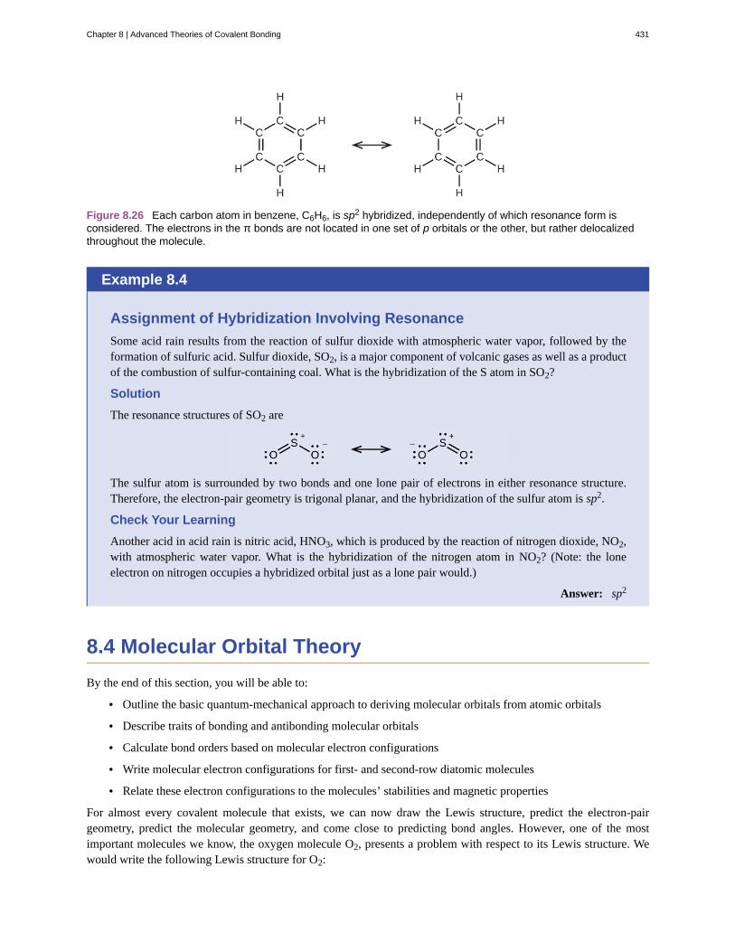
Figure 8.26 Each carbon atom in benzene, C6H6, is sp2 hybridized, independently of which resonance form isconsidered. The electrons in the π bonds are not located in one set of p orbitals or the other, but rather delocalizedthroughout the molecule.
Example 8.4
Assignment of Hybridization Involving Resonance
Some acid rain results from the reaction of sulfur dioxide with atmospheric water vapor, followed by theformation of sulfuric acid. Sulfur dioxide, SO2, is a major component of volcanic gases as well as a productof the combustion of sulfur-containing coal. What is the hybridization of the S atom in SO2?
Solution
The resonance structures of SO2 are
The sulfur atom is surrounded by two bonds and one lone pair of electrons in either resonance structure.Therefore, the electron-pair geometry is trigonal planar, and the hybridization of the sulfur atom is sp2.
Check Your Learning
Another acid in acid rain is nitric acid, HNO3, which is produced by the reaction of nitrogen dioxide, NO2,with atmospheric water vapor. What is the hybridization of the nitrogen atom in NO2? (Note: the loneelectron on nitrogen occupies a hybridized orbital just as a lone pair would.)
Answer: sp2
8.4 Molecular Orbital Theory
By the end of this section, you will be able to:
• Outline the basic quantum-mechanical approach to deriving molecular orbitals from atomic orbitals
• Describe traits of bonding and antibonding molecular orbitals
• Calculate bond orders based on molecular electron configurations
• Write molecular electron configurations for first- and second-row diatomic molecules
• Relate these electron configurations to the molecules’ stabilities and magnetic properties
For almost every covalent molecule that exists, we can now draw the Lewis structure, predict the electron-pairgeometry, predict the molecular geometry, and come close to predicting bond angles. However, one of the mostimportant molecules we know, the oxygen molecule O2, presents a problem with respect to its Lewis structure. Wewould write the following Lewis structure for O2:
Chapter 8 | Advanced Theories of Covalent Bonding 431

This electronic structure adheres to all the rules governing Lewis theory. There is an O=O double bond, and eachoxygen atom has eight electrons around it. However, this picture is at odds with the magnetic behavior of oxygen.By itself, O2 is not magnetic, but it is attracted to magnetic fields. Thus, when we pour liquid oxygen past a strongmagnet, it collects between the poles of the magnet and defies gravity, as in Figure 8.1. Such attraction to a magneticfield is called paramagnetism, and it arises in molecules that have unpaired electrons. And yet, the Lewis structureof O2 indicates that all electrons are paired. How do we account for this discrepancy?
Magnetic susceptibility measures the force experienced by a substance in a magnetic field. When we compare theweight of a sample to the weight measured in a magnetic field (Figure 8.27), paramagnetic samples that are attractedto the magnet will appear heavier because of the force exerted by the magnetic field. We can calculate the number ofunpaired electrons based on the increase in weight.
Figure 8.27 A Gouy balance compares the mass of a sample in the presence of a magnetic field with the mass withthe electromagnet turned off to determine the number of unpaired electrons in a sample.
Experiments show that each O2 molecule has two unpaired electrons. The Lewis-structure model does not predict thepresence of these two unpaired electrons. Unlike oxygen, the apparent weight of most molecules decreases slightly inthe presence of an inhomogeneous magnetic field. Materials in which all of the electrons are paired are diamagneticand weakly repel a magnetic field. Paramagnetic and diamagnetic materials do not act as permanent magnets. Only inthe presence of an applied magnetic field do they demonstrate attraction or repulsion.
432 Chapter 8 | Advanced Theories of Covalent Bonding
This OpenStax book is available for free at http://cnx.org/content/col26069/1.5

Water, like most molecules, contains all paired electrons. Living things contain a large percentage ofwater, so they demonstrate diamagnetic behavior. If you place a frog near a sufficiently large magnet, itwill levitate. You can see videos (http://openstaxcollege.org/l/16diamagnetic) of diamagnetic floatingfrogs, strawberries, and more.
Molecular orbital theory (MO theory) provides an explanation of chemical bonding that accounts for theparamagnetism of the oxygen molecule. It also explains the bonding in a number of other molecules, such asviolations of the octet rule and more molecules with more complicated bonding (beyond the scope of this text) that aredifficult to describe with Lewis structures. Additionally, it provides a model for describing the energies of electrons ina molecule and the probable location of these electrons. Unlike valence bond theory, which uses hybrid orbitals thatare assigned to one specific atom, MO theory uses the combination of atomic orbitals to yield molecular orbitals thatare delocalized over the entire molecule rather than being localized on its constituent atoms. MO theory also helps usunderstand why some substances are electrical conductors, others are semiconductors, and still others are insulators.Table 8.2 summarizes the main points of the two complementary bonding theories. Both theories provide different,useful ways of describing molecular structure.
Comparison of Bonding Theories
Valence Bond Theory Molecular Orbital Theory
considers bonds as localized between one pair of atomsconsiders electrons delocalized throughout the
entire molecule
creates bonds from overlap of atomic orbitals (s, p, d…)and hybrid orbitals (sp, sp2, sp3…)
combines atomic orbitals to form molecularorbitals (σ, σ*, π, π*)
forms σ or π bondscreates bonding and antibonding interactions
based on which orbitals are filled
predicts molecular shape based on the number of regionsof electron density
predicts the arrangement of electrons in molecules
needs multiple structures to describe resonance
Table 8.2
Molecular orbital theory describes the distribution of electrons in molecules in much the same way that thedistribution of electrons in atoms is described using atomic orbitals. Using quantum mechanics, the behavior of anelectron in a molecule is still described by a wave function, Ψ, analogous to the behavior in an atom. Just like electronsaround isolated atoms, electrons around atoms in molecules are limited to discrete (quantized) energies. The regionof space in which a valence electron in a molecule is likely to be found is called a molecular orbital (Ψ2). Like anatomic orbital, a molecular orbital is full when it contains two electrons with opposite spin.
We will consider the molecular orbitals in molecules composed of two identical atoms (H2 or Cl2, for example). Suchmolecules are called homonuclear diatomic molecules. In these diatomic molecules, several types of molecularorbitals occur.
The mathematical process of combining atomic orbitals to generate molecular orbitals is called the linearcombination of atomic orbitals (LCAO). The wave function describes the wavelike properties of an electron.Molecular orbitals are combinations of atomic orbital wave functions. Combining waves can lead to constructiveinterference, in which peaks line up with peaks, or destructive interference, in which peaks line up with troughs(Figure 8.28). In orbitals, the waves are three dimensional, and they combine with in-phase waves producing regions
Link to Learning
Chapter 8 | Advanced Theories of Covalent Bonding 433

with a higher probability of electron density and out-of-phase waves producing nodes, or regions of no electrondensity.
Figure 8.28 (a) When in-phase waves combine, constructive interference produces a wave with greater amplitude.(b) When out-of-phase waves combine, destructive interference produces a wave with less (or no) amplitude.
There are two types of molecular orbitals that can form from the overlap of two atomic s orbitals on adjacent atoms.The two types are illustrated in Figure 8.29. The in-phase combination produces a lower energy σs molecularorbital (read as "sigma-s") in which most of the electron density is directly between the nuclei. The out-of-phaseaddition (which can also be thought of as subtracting the wave functions) produces a higher energy molecular orbital(read as "sigma-s-star") molecular orbital in which there is a node between the nuclei. The asterisk signifies that theorbital is an antibonding orbital. Electrons in a σs orbital are attracted by both nuclei at the same time and are morestable (of lower energy) than they would be in the isolated atoms. Adding electrons to these orbitals creates a forcethat holds the two nuclei together, so we call these orbitals bonding orbitals. Electrons in the σs* orbitals are located
well away from the region between the two nuclei. The attractive force between the nuclei and these electrons pullsthe two nuclei apart. Hence, these orbitals are called antibonding orbitals. Electrons fill the lower-energy bondingorbital before the higher-energy antibonding orbital, just as they fill lower-energy atomic orbitals before they fillhigher-energy atomic orbitals.
Figure 8.29 Sigma (σ) and sigma-star (σ*) molecular orbitals are formed by the combination of two s atomic orbitals.The plus (+) signs indicate the locations of nuclei.
You can watch animations (http://openstaxcollege.org/l/16molecorbital) visualizing the calculatedatomic orbitals combining to form various molecular orbitals at the Orbitron website.
Link to Learning
434 Chapter 8 | Advanced Theories of Covalent Bonding
This OpenStax book is available for free at http://cnx.org/content/col26069/1.5

In p orbitals, the wave function gives rise to two lobes with opposite phases, analogous to how a two-dimensionalwave has both parts above and below the average. We indicate the phases by shading the orbital lobes different colors.When orbital lobes of the same phase overlap, constructive wave interference increases the electron density. Whenregions of opposite phase overlap, the destructive wave interference decreases electron density and creates nodes.When p orbitals overlap end to end, they create σ and σ* orbitals (Figure 8.30). If two atoms are located alongthe x-axis in a Cartesian coordinate system, the two px orbitals overlap end to end and form σpx (bonding) and σ px*
(antibonding) (read as "sigma-p-x" and "sigma-p-x star," respectively). Just as with s-orbital overlap, the asteriskindicates the orbital with a node between the nuclei, which is a higher-energy, antibonding orbital.
Figure 8.30 Combining wave functions of two p atomic orbitals along the internuclear axis creates two molecular
orbitals, σp and σ p* .
The side-by-side overlap of two p orbitals gives rise to a pi (π) bonding molecular orbital and a π* antibondingmolecular orbital, as shown in Figure 8.31. In valence bond theory, we describe π bonds as containing a nodalplane containing the internuclear axis and perpendicular to the lobes of the p orbitals, with electron density on eitherside of the node. In molecular orbital theory, we describe the π orbital by this same shape, and a π bond exists whenthis orbital contains electrons. Electrons in this orbital interact with both nuclei and help hold the two atoms together,making it a bonding orbital. For the out-of-phase combination, there are two nodal planes created, one along theinternuclear axis and a perpendicular one between the nuclei.
Figure 8.31 Side-by-side overlap of each two p orbitals results in the formation of two π molecular orbitals.Combining the out-of-phase orbitals results in an antibonding molecular orbital with two nodes. One contains theinternuclear axis, and one is perpendicular to the axis. Combining the in-phase orbitals results in a bonding orbital.There is a node (blue) containing the internuclear axis with the two lobes of the orbital located above and below thisnode.
Chapter 8 | Advanced Theories of Covalent Bonding 435

In the molecular orbitals of diatomic molecules, each atom also has two sets of p orbitals oriented side by side (py
and pz), so these four atomic orbitals combine pairwise to create two π orbitals and two π* orbitals. The πpy and π py*
orbitals are oriented at right angles to the πpz and π pz* orbitals. Except for their orientation, the πpy and πpz orbitals
are identical and have the same energy; they are degenerate orbitals. The π py* and π pz* antibonding orbitals are also
degenerate and identical except for their orientation. A total of six molecular orbitals results from the combination ofthe six atomic p orbitals in two atoms: σpx and σ px* , πpy and π py* , πpz and π pz* .
Example 8.5
Molecular Orbitals
Predict what type (if any) of molecular orbital would result from adding the wave functions so each pair oforbitals shown overlap. The orbitals are all similar in energy.
Solution
(a) is an in-phase combination, resulting in a σ3p orbital
(b) will not result in a new orbital because the in-phase component (bottom) and out-of-phase component(top) cancel out. Only orbitals with the correct alignment can combine.
(c) is an out-of-phase combination, resulting in a π3p* orbital.
Check Your Learning
Label the molecular orbital shown as σ or π, bonding or antibonding and indicate where the node occurs.
Answer: The orbital is located along the internuclear axis, so it is a σ orbital. There is a node bisecting theinternuclear axis, so it is an antibonding orbital.
Walter Kohn: Nobel Laureate
Walter Kohn (Figure 8.32) is a theoretical physicist who studies the electronic structure of solids. His workcombines the principles of quantum mechanics with advanced mathematical techniques. This technique, calleddensity functional theory, makes it possible to compute properties of molecular orbitals, including their shapeand energies. Kohn and mathematician John Pople were awarded the Nobel Prize in Chemistry in 1998 fortheir contributions to our understanding of electronic structure. Kohn also made significant contributions to the
Portrait of a Chemist
436 Chapter 8 | Advanced Theories of Covalent Bonding
This OpenStax book is available for free at http://cnx.org/content/col26069/1.5

physics of semiconductors.
Figure 8.32 Walter Kohn developed methods to describe molecular orbitals. (credit: image courtesy ofWalter Kohn)
Kohn’s biography has been remarkable outside the realm of physical chemistry as well. He was born in Austria,and during World War II he was part of the Kindertransport program that rescued 10,000 children from the Naziregime. His summer jobs included discovering gold deposits in Canada and helping Polaroid explain how itsinstant film worked. Although he is now an emeritus professor, he is still actively working on projects involvingglobal warming and renewable energy.
Computational Chemistry in Drug Design
While the descriptions of bonding described in this chapter involve many theoretical concepts, they alsohave many practical, real-world applications. For example, drug design is an important field that uses ourunderstanding of chemical bonding to develop pharmaceuticals. This interdisciplinary area of study usesbiology (understanding diseases and how they operate) to identify specific targets, such as a binding sitethat is involved in a disease pathway. By modeling the structures of the binding site and potential drugs,computational chemists can predict which structures can fit together and how effectively they will bind (seeFigure 8.33). Thousands of potential candidates can be narrowed down to a few of the most promisingcandidates. These candidate molecules are then carefully tested to determine side effects, how effectively theycan be transported through the body, and other factors. Dozens of important new pharmaceuticals have beendiscovered with the aid of computational chemistry, and new research projects are underway.
How Sciences Interconnect
Chapter 8 | Advanced Theories of Covalent Bonding 437

Figure 8.33 The molecule shown, HIV-1 protease, is an important target for pharmaceutical research. Bydesigning molecules that bind to this protein, scientists are able to drastically inhibit the progress of thedisease.
Molecular Orbital Energy Diagrams
The relative energy levels of atomic and molecular orbitals are typically shown in a molecular orbital diagram(Figure 8.34). For a diatomic molecule, the atomic orbitals of one atom are shown on the left, and those of theother atom are shown on the right. Each horizontal line represents one orbital that can hold two electrons. Themolecular orbitals formed by the combination of the atomic orbitals are shown in the center. Dashed lines show whichof the atomic orbitals combine to form the molecular orbitals. For each pair of atomic orbitals that combine, onelower-energy (bonding) molecular orbital and one higher-energy (antibonding) orbital result. Thus we can see thatcombining the six 2p atomic orbitals results in three bonding orbitals (one σ and two π) and three antibonding orbitals(one σ* and two π*).
We predict the distribution of electrons in these molecular orbitals by filling the orbitals in the same way that wefill atomic orbitals, by the Aufbau principle. Lower-energy orbitals fill first, electrons spread out among degenerateorbitals before pairing, and each orbital can hold a maximum of two electrons with opposite spins (Figure 8.34).Just as we write electron configurations for atoms, we can write the molecular electronic configuration by listingthe orbitals with superscripts indicating the number of electrons present. For clarity, we place parentheses aroundmolecular orbitals with the same energy. In this case, each orbital is at a different energy, so parentheses separate eachorbital. Thus we would expect a diatomic molecule or ion containing seven electrons (such as Be2
+) would have the
molecular electron configuration (σ1s)2 (σ1s* )2 (σ2s)
2 (σ2s* )1. It is common to omit the core electrons from molecular
orbital diagrams and configurations and include only the valence electrons.
438 Chapter 8 | Advanced Theories of Covalent Bonding
This OpenStax book is available for free at http://cnx.org/content/col26069/1.5
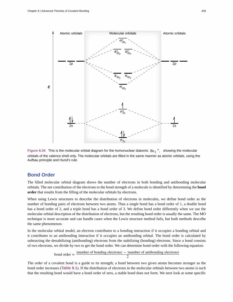
Figure 8.34 This is the molecular orbital diagram for the homonuclear diatomic Be2+, showing the molecular
orbitals of the valence shell only. The molecular orbitals are filled in the same manner as atomic orbitals, using theAufbau principle and Hund’s rule.
Bond Order
The filled molecular orbital diagram shows the number of electrons in both bonding and antibonding molecularorbitals. The net contribution of the electrons to the bond strength of a molecule is identified by determining the bondorder that results from the filling of the molecular orbitals by electrons.
When using Lewis structures to describe the distribution of electrons in molecules, we define bond order as thenumber of bonding pairs of electrons between two atoms. Thus a single bond has a bond order of 1, a double bondhas a bond order of 2, and a triple bond has a bond order of 3. We define bond order differently when we use themolecular orbital description of the distribution of electrons, but the resulting bond order is usually the same. The MOtechnique is more accurate and can handle cases when the Lewis structure method fails, but both methods describethe same phenomenon.
In the molecular orbital model, an electron contributes to a bonding interaction if it occupies a bonding orbital andit contributes to an antibonding interaction if it occupies an antibonding orbital. The bond order is calculated bysubtracting the destabilizing (antibonding) electrons from the stabilizing (bonding) electrons. Since a bond consistsof two electrons, we divide by two to get the bond order. We can determine bond order with the following equation:
bond order =⎛⎝number of bonding electrons⎞⎠ − ⎛
⎝number of antibonding electrons⎞⎠2
The order of a covalent bond is a guide to its strength; a bond between two given atoms becomes stronger as thebond order increases (Table 8.1). If the distribution of electrons in the molecular orbitals between two atoms is suchthat the resulting bond would have a bond order of zero, a stable bond does not form. We next look at some specific
Chapter 8 | Advanced Theories of Covalent Bonding 439

examples of MO diagrams and bond orders.
Bonding in Diatomic Molecules
A dihydrogen molecule (H2) forms from two hydrogen atoms. When the atomic orbitals of the two atoms combine,the electrons occupy the molecular orbital of lowest energy, the σ1s bonding orbital. A dihydrogen molecule, H2,readily forms because the energy of a H2 molecule is lower than that of two H atoms. The σ1s orbital that containsboth electrons is lower in energy than either of the two 1s atomic orbitals.
A molecular orbital can hold two electrons, so both electrons in the H2 molecule are in the σ1s bonding orbital; theelectron configuration is (σ1s)
2. We represent this configuration by a molecular orbital energy diagram (Figure
8.35) in which a single upward arrow indicates one electron in an orbital, and two (upward and downward) arrowsindicate two electrons of opposite spin.
Figure 8.35 The molecular orbital energy diagram predicts that H2 will be a stable molecule with lower energy thanthe separated atoms.
A dihydrogen molecule contains two bonding electrons and no antibonding electrons so we have
bond order in H2 = (2 − 0)2 = 1
Because the bond order for the H–H bond is equal to 1, the bond is a single bond.
A helium atom has two electrons, both of which are in its 1s orbital. Two helium atoms do not combine to form adihelium molecule, He2, with four electrons, because the stabilizing effect of the two electrons in the lower-energybonding orbital would be offset by the destabilizing effect of the two electrons in the higher-energy antibondingmolecular orbital. We would write the hypothetical electron configuration of He2 as (σ1s)
2 (σ1s* )2 as in Figure 8.36.
The net energy change would be zero, so there is no driving force for helium atoms to form the diatomic molecule.In fact, helium exists as discrete atoms rather than as diatomic molecules. The bond order in a hypothetical diheliummolecule would be zero.
bond order in He2 = (2 − 2)2 = 0
A bond order of zero indicates that no bond is formed between two atoms.
440 Chapter 8 | Advanced Theories of Covalent Bonding
This OpenStax book is available for free at http://cnx.org/content/col26069/1.5

Figure 8.36 The molecular orbital energy diagram predicts that He2 will not be a stable molecule, since it has equalnumbers of bonding and antibonding electrons.
The Diatomic Molecules of the Second Period
Eight possible homonuclear diatomic molecules might be formed by the atoms of the second period of the periodictable: Li2, Be2, B2, C2, N2, O2, F2, and Ne2. However, we can predict that the Be2 molecule and the Ne2 moleculewould not be stable. We can see this by a consideration of the molecular electron configurations (Table 8.3).
We predict valence molecular orbital electron configurations just as we predict electron configurations of atoms.Valence electrons are assigned to valence molecular orbitals with the lowest possible energies. Consistent with Hund’srule, whenever there are two or more degenerate molecular orbitals, electrons fill each orbital of that type singlybefore any pairing of electrons takes place.
As we saw in valence bond theory, σ bonds are generally more stable than π bonds formed from degenerate atomicorbitals. Similarly, in molecular orbital theory, σ orbitals are usually more stable than π orbitals. However, this isnot always the case. The MOs for the valence orbitals of the second period are shown in Figure 8.37. Looking atNe2 molecular orbitals, we see that the order is consistent with the generic diagram shown in the previous section.However, for atoms with three or fewer electrons in the p orbitals (Li through N) we observe a different pattern,in which the σp orbital is higher in energy than the πp set. Obtain the molecular orbital diagram for a homonucleardiatomic ion by adding or subtracting electrons from the diagram for the neutral molecule.
Chapter 8 | Advanced Theories of Covalent Bonding 441
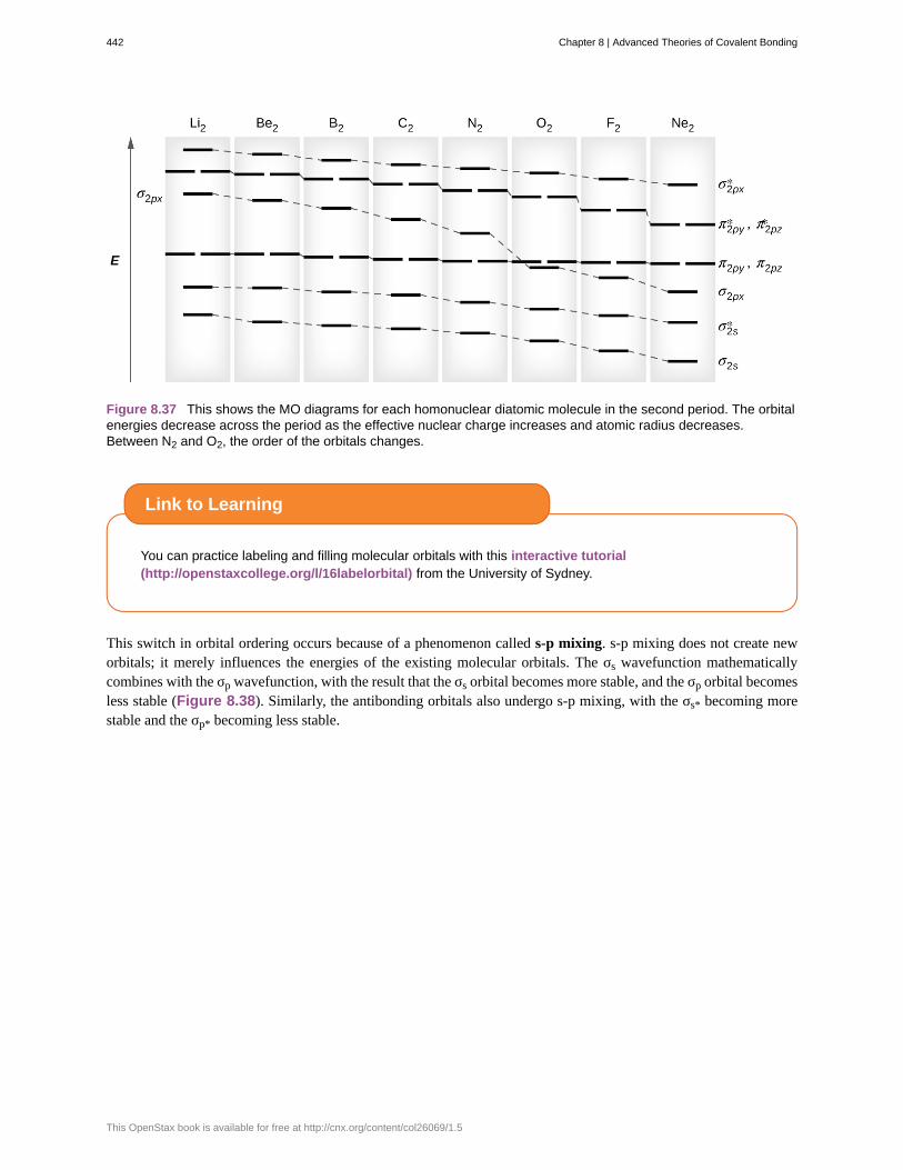
Figure 8.37 This shows the MO diagrams for each homonuclear diatomic molecule in the second period. The orbitalenergies decrease across the period as the effective nuclear charge increases and atomic radius decreases.Between N2 and O2, the order of the orbitals changes.
You can practice labeling and filling molecular orbitals with this interactive tutorial(http://openstaxcollege.org/l/16labelorbital) from the University of Sydney.
This switch in orbital ordering occurs because of a phenomenon called s-p mixing. s-p mixing does not create neworbitals; it merely influences the energies of the existing molecular orbitals. The σs wavefunction mathematicallycombines with the σp wavefunction, with the result that the σs orbital becomes more stable, and the σp orbital becomesless stable (Figure 8.38). Similarly, the antibonding orbitals also undergo s-p mixing, with the σs* becoming morestable and the σp* becoming less stable.
Link to Learning
442 Chapter 8 | Advanced Theories of Covalent Bonding
This OpenStax book is available for free at http://cnx.org/content/col26069/1.5
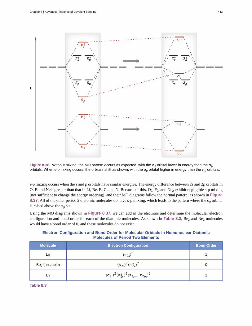
Figure 8.38 Without mixing, the MO pattern occurs as expected, with the σp orbital lower in energy than the σporbitals. When s-p mixing occurs, the orbitals shift as shown, with the σp orbital higher in energy than the πp orbitals.
s-p mixing occurs when the s and p orbitals have similar energies. The energy difference between 2s and 2p orbitals inO, F, and Neis greater than that in Li, Be, B, C, and N. Because of this, O2, F2, and Ne2 exhibit negligible s-p mixing(not sufficient to change the energy ordering), and their MO diagrams follow the normal pattern, as shown in Figure8.37. All of the other period 2 diatomic molecules do have s-p mixing, which leads to the pattern where the σp orbitalis raised above the πp set.
Using the MO diagrams shown in Figure 8.37, we can add in the electrons and determine the molecular electronconfiguration and bond order for each of the diatomic molecules. As shown in Table 8.3, Be2 and Ne2 moleculeswould have a bond order of 0, and these molecules do not exist.
Electron Configuration and Bond Order for Molecular Orbitals in Homonuclear DiatomicMolecules of Period Two Elements
Molecule Electron Configuration Bond Order
Li2 (σ2s)2 1
Be2 (unstable) (σ2s)2 (σ2s* )2 0
B2 (σ2s)2 (σ2s* )2 (π2py, π2pz)
2 1
Table 8.3
Chapter 8 | Advanced Theories of Covalent Bonding 443
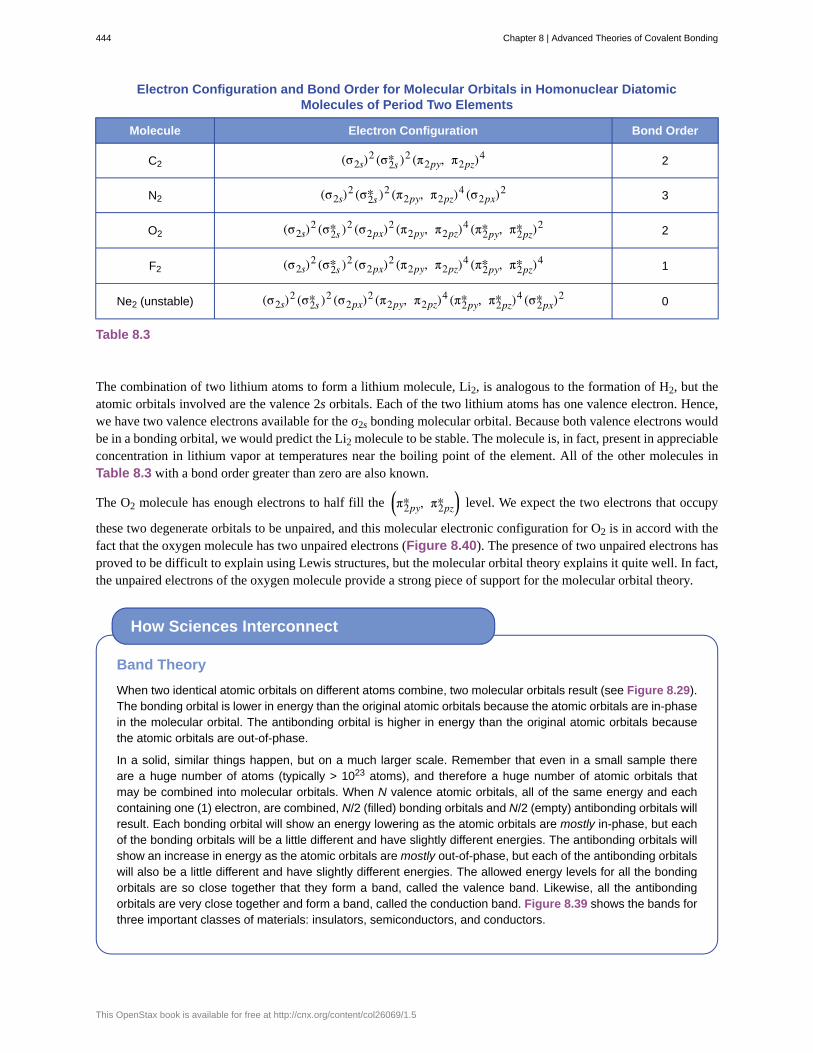
Electron Configuration and Bond Order for Molecular Orbitals in Homonuclear DiatomicMolecules of Period Two Elements
Molecule Electron Configuration Bond Order
C2 (σ2s)2 (σ2s* )2 (π2py, π2pz)
4 2
N2 (σ2s)2 (σ2s* )2 (π2py, π2pz)
4 (σ2px)2 3
O2 (σ2s)2 (σ2s* )2 (σ2px)
2 (π2py, π2pz)4 (π2py* , π2pz* )2 2
F2 (σ2s)2 (σ2s* )2 (σ2px)
2 (π2py, π2pz)4 (π2py* , π2pz* )4 1
Ne2 (unstable) (σ2s)2 (σ2s* )2 (σ2px)
2 (π2py, π2pz)4 (π2py* , π2pz* )4 (σ2px* )2 0
Table 8.3
The combination of two lithium atoms to form a lithium molecule, Li2, is analogous to the formation of H2, but theatomic orbitals involved are the valence 2s orbitals. Each of the two lithium atoms has one valence electron. Hence,we have two valence electrons available for the σ2s bonding molecular orbital. Because both valence electrons wouldbe in a bonding orbital, we would predict the Li2 molecule to be stable. The molecule is, in fact, present in appreciableconcentration in lithium vapor at temperatures near the boiling point of the element. All of the other molecules inTable 8.3 with a bond order greater than zero are also known.
The O2 molecule has enough electrons to half fill the ⎛⎝π2py* , π2pz* ⎞⎠ level. We expect the two electrons that occupy
these two degenerate orbitals to be unpaired, and this molecular electronic configuration for O2 is in accord with thefact that the oxygen molecule has two unpaired electrons (Figure 8.40). The presence of two unpaired electrons hasproved to be difficult to explain using Lewis structures, but the molecular orbital theory explains it quite well. In fact,the unpaired electrons of the oxygen molecule provide a strong piece of support for the molecular orbital theory.
Band Theory
When two identical atomic orbitals on different atoms combine, two molecular orbitals result (see Figure 8.29).The bonding orbital is lower in energy than the original atomic orbitals because the atomic orbitals are in-phasein the molecular orbital. The antibonding orbital is higher in energy than the original atomic orbitals becausethe atomic orbitals are out-of-phase.
In a solid, similar things happen, but on a much larger scale. Remember that even in a small sample thereare a huge number of atoms (typically > 1023 atoms), and therefore a huge number of atomic orbitals thatmay be combined into molecular orbitals. When N valence atomic orbitals, all of the same energy and eachcontaining one (1) electron, are combined, N/2 (filled) bonding orbitals and N/2 (empty) antibonding orbitals willresult. Each bonding orbital will show an energy lowering as the atomic orbitals are mostly in-phase, but eachof the bonding orbitals will be a little different and have slightly different energies. The antibonding orbitals willshow an increase in energy as the atomic orbitals are mostly out-of-phase, but each of the antibonding orbitalswill also be a little different and have slightly different energies. The allowed energy levels for all the bondingorbitals are so close together that they form a band, called the valence band. Likewise, all the antibondingorbitals are very close together and form a band, called the conduction band. Figure 8.39 shows the bands forthree important classes of materials: insulators, semiconductors, and conductors.
How Sciences Interconnect
444 Chapter 8 | Advanced Theories of Covalent Bonding
This OpenStax book is available for free at http://cnx.org/content/col26069/1.5

Figure 8.39 Molecular orbitals in solids are so closely spaced that they are described as bands. The valenceband is lower in energy and the conduction band is higher in energy. The type of solid is determined by thesize of the “band gap” between the valence and conduction bands. Only a very small amount of energy isrequired to move electrons from the valence band to the conduction band in a conductor, and so they conductelectricity well. In an insulator, the band gap is large, so that very few electrons move, and they are poorconductors of electricity. Semiconductors are in between: they conduct electricity better than insulators, butnot as well as conductors.
In order to conduct electricity, electrons must move from the filled valence band to the empty conduction bandwhere they can move throughout the solid. The size of the band gap, or the energy difference between thetop of the valence band and the bottom of the conduction band, determines how easy it is to move electronsbetween the bands. Only a small amount of energy is required in a conductor because the band gap isvery small. This small energy difference is “easy” to overcome, so they are good conductors of electricity. Inan insulator, the band gap is so “large” that very few electrons move into the conduction band; as a result,insulators are poor conductors of electricity. Semiconductors conduct electricity when “moderate” amounts ofenergy are provided to move electrons out of the valence band and into the conduction band. Semiconductors,such as silicon, are found in many electronics.
Semiconductors are used in devices such as computers, smartphones, and solar cells. Solar cells produceelectricity when light provides the energy to move electrons out of the valence band. The electricity that isgenerated may then be used to power a light or tool, or it can be stored for later use by charging a battery. Asof December 2014, up to 46% of the energy in sunlight could be converted into electricity using solar cells.
Example 8.6
Molecular Orbital Diagrams, Bond Order, and Number of UnpairedElectrons
Draw the molecular orbital diagram for the oxygen molecule, O2. From this diagram, calculate the bondorder for O2. How does this diagram account for the paramagnetism of O2?
Solution
We draw a molecular orbital energy diagram similar to that shown in Figure 8.37. Each oxygen atomcontributes six electrons, so the diagram appears as shown in Figure 8.40.
Chapter 8 | Advanced Theories of Covalent Bonding 445

Figure 8.40 The molecular orbital energy diagram for O2 predicts two unpaired electrons.
We calculate the bond order as
O2 = (8 − 4)2 = 2
Oxygen's paramagnetism is explained by the presence of two unpaired electrons in the (π2py, π2pz)*molecular orbitals.
Check Your Learning
The main component of air is N2. From the molecular orbital diagram of N2, predict its bond order andwhether it is diamagnetic or paramagnetic.
Answer: N2 has a bond order of 3 and is diamagnetic.
Example 8.7
Ion Predictions with MO Diagrams
Give the molecular orbital configuration for the valence electrons in C22−. Will this ion be stable?
Solution
Looking at the appropriate MO diagram, we see that the π orbitals are lower in energy than the σp orbital.
The valence electron configuration for C2 is (σ2s)2 (σ2s* )2 (π2py, π2pz)
4. Adding two more electrons to
446 Chapter 8 | Advanced Theories of Covalent Bonding
This OpenStax book is available for free at http://cnx.org/content/col26069/1.5

generate the C22− anion will give a valence electron configuration of (σ2s)
2 (σ2s* )2 (π2py, π2pz)4 (σ2px)
2.Since this has six more bonding electrons than antibonding, the bond order will be 3, and the ion should bestable.
Check Your Learning
How many unpaired electrons would be present on a Be22− ion? Would it be paramagnetic or
diamagnetic?
Answer: two, paramagnetic
Creating molecular orbital diagrams for molecules with more than two atoms relies on the same basicideas as the diatomic examples presented here. However, with more atoms, computers are required tocalculate how the atomic orbitals combine. See three-dimensional drawings(http://openstaxcollege.org/l/16orbitaldiag) of the molecular orbitals for C6H6.
Link to Learning
Chapter 8 | Advanced Theories of Covalent Bonding 447

antibonding orbital
bond order
bonding orbital
degenerate orbitals
diamagnetism
homonuclear diatomic molecule
hybrid orbital
hybridization
linear combination of atomic orbitals
molecular orbital
molecular orbital diagram
molecular orbital theory
node
overlap
paramagnetism
pi bond (π bond)
s-p mixing
sigma bond (σ bond)
sp hybrid orbital
sp2 hybrid orbital
sp3 hybrid orbital
sp3d hybrid orbital
Key Terms
molecular orbital located outside of the region between two nuclei; electrons in an antibondingorbital destabilize the molecule
number of pairs of electrons between two atoms; it can be found by the number of bonds in a Lewisstructure or by the difference between the number of bonding and antibonding electrons divided by two
molecular orbital located between two nuclei; electrons in a bonding orbital stabilize a molecule
orbitals that have the same energy
phenomenon in which a material is not magnetic itself but is repelled by a magnetic field; it occurswhen there are only paired electrons present
molecule consisting of two identical atoms
orbital created by combining atomic orbitals on a central atom
model that describes the changes in the atomic orbitals of an atom when it forms a covalentcompound
technique for combining atomic orbitals to create molecular orbitals
region of space in which an electron has a high probability of being found in a molecule
visual representation of the relative energy levels of molecular orbitals
model that describes the behavior of electrons delocalized throughout a molecule interms of the combination of atomic wave functions
plane separating different lobes of orbitals, where the probability of finding an electron is zero
coexistence of orbitals from two different atoms sharing the same region of space, leading to the formationof a covalent bond
phenomenon in which a material is not magnetic itself but is attracted to a magnetic field; it occurswhen there are unpaired electrons present
covalent bond formed by side-by-side overlap of atomic orbitals; the electron density is found onopposite sides of the internuclear axis
change that causes σp orbitals to be less stable than πp orbitals due to the mixing of s and p-basedmolecular orbitals of similar energies.
covalent bond formed by overlap of atomic orbitals along the internuclear axis
one of a set of two orbitals with a linear arrangement that results from combining one s and one porbital
one of a set of three orbitals with a trigonal planar arrangement that results from combining ones and two p orbitals
one of a set of four orbitals with a tetrahedral arrangement that results from combining one s andthree p orbitals
one of a set of five orbitals with a trigonal bipyramidal arrangement that results from
448 Chapter 8 | Advanced Theories of Covalent Bonding
This OpenStax book is available for free at http://cnx.org/content/col26069/1.5

sp3d2 hybrid orbital
valence bond theory
π bonding orbital
π* bonding orbital
σ bonding orbital
σ* bonding orbital
combining one s, three p, and one d orbital
one of a set of six orbitals with an octahedral arrangement that results from combining one s,three p, and two d orbitals
description of bonding that involves atomic orbitals overlapping to form σ or π bonds, withinwhich pairs of electrons are shared
molecular orbital formed by side-by-side overlap of atomic orbitals, in which the electrondensity is found on opposite sides of the internuclear axis
antibonding molecular orbital formed by out of phase side-by-side overlap of atomic orbitals, inwhich the electron density is found on both sides of the internuclear axis, and there is a node between the nuclei
molecular orbital in which the electron density is found along the axis of the bond
antibonding molecular orbital formed by out-of-phase overlap of atomic orbital along the axisof the bond, generating a node between the nuclei
Key Equations
• bond order =⎛⎝number of bonding electron⎞⎠− ⎛
⎝number of antibonding electrons⎞⎠2
Summary
8.1 Valence Bond TheoryValence bond theory describes bonding as a consequence of the overlap of two separate atomic orbitals on differentatoms that creates a region with one pair of electrons shared between the two atoms. When the orbitals overlap alongan axis containing the nuclei, they form a σ bond. When they overlap in a fashion that creates a node along this axis,they form a π bond.
8.2 Hybrid Atomic OrbitalsWe can use hybrid orbitals, which are mathematical combinations of some or all of the valence atomic orbitals, todescribe the electron density around covalently bonded atoms. These hybrid orbitals either form sigma (σ) bondsdirected toward other atoms of the molecule or contain lone pairs of electrons. We can determine the type ofhybridization around a central atom from the geometry of the regions of electron density about it. Two such regionsimply sp hybridization; three, sp2 hybridization; four, sp3 hybridization; five, sp3d hybridization; and six, sp3d2
hybridization. Pi (π) bonds are formed from unhybridized atomic orbitals (p or d orbitals).
8.3 Multiple BondsMultiple bonds consist of a σ bond located along the axis between two atoms and one or two π bonds. The σ bondsare usually formed by the overlap of hybridized atomic orbitals, while the π bonds are formed by the side-by-sideoverlap of unhybridized orbitals. Resonance occurs when there are multiple unhybridized orbitals with the appropriatealignment to overlap, so the placement of π bonds can vary.
8.4 Molecular Orbital TheoryMolecular orbital (MO) theory describes the behavior of electrons in a molecule in terms of combinations of theatomic wave functions. The resulting molecular orbitals may extend over all the atoms in the molecule. Bondingmolecular orbitals are formed by in-phase combinations of atomic wave functions, and electrons in these orbitalsstabilize a molecule. Antibonding molecular orbitals result from out-of-phase combinations of atomic wave functionsand electrons in these orbitals make a molecule less stable. Molecular orbitals located along an internuclear axis arecalled σ MOs. They can be formed from s orbitals or from p orbitals oriented in an end-to-end fashion. Molecularorbitals formed from p orbitals oriented in a side-by-side fashion have electron density on opposite sides of the
Chapter 8 | Advanced Theories of Covalent Bonding 449
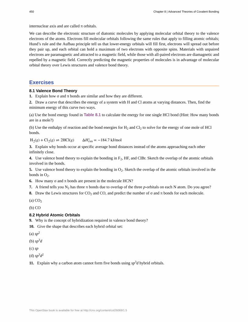
internuclear axis and are called π orbitals.
We can describe the electronic structure of diatomic molecules by applying molecular orbital theory to the valenceelectrons of the atoms. Electrons fill molecular orbitals following the same rules that apply to filling atomic orbitals;Hund’s rule and the Aufbau principle tell us that lower-energy orbitals will fill first, electrons will spread out beforethey pair up, and each orbital can hold a maximum of two electrons with opposite spins. Materials with unpairedelectrons are paramagnetic and attracted to a magnetic field, while those with all-paired electrons are diamagnetic andrepelled by a magnetic field. Correctly predicting the magnetic properties of molecules is in advantage of molecularorbital theory over Lewis structures and valence bond theory.
Exercises
8.1 Valence Bond Theory1. Explain how σ and π bonds are similar and how they are different.
2. Draw a curve that describes the energy of a system with H and Cl atoms at varying distances. Then, find theminimum energy of this curve two ways.
(a) Use the bond energy found in Table 8.1 to calculate the energy for one single HCl bond (Hint: How many bondsare in a mole?)
(b) Use the enthalpy of reaction and the bond energies for H2 and Cl2 to solve for the energy of one mole of HClbonds.
H2(g) + Cl2(g) ⇌ 2HCl(g) ΔHrxn° = −184.7 kJ/mol
3. Explain why bonds occur at specific average bond distances instead of the atoms approaching each otherinfinitely close.
4. Use valence bond theory to explain the bonding in F2, HF, and ClBr. Sketch the overlap of the atomic orbitalsinvolved in the bonds.
5. Use valence bond theory to explain the bonding in O2. Sketch the overlap of the atomic orbitals involved in thebonds in O2.
6. How many σ and π bonds are present in the molecule HCN?
7. A friend tells you N2 has three π bonds due to overlap of the three p-orbitals on each N atom. Do you agree?
8. Draw the Lewis structures for CO2 and CO, and predict the number of σ and π bonds for each molecule.
(a) CO2
(b) CO
8.2 Hybrid Atomic Orbitals9. Why is the concept of hybridization required in valence bond theory?
10. Give the shape that describes each hybrid orbital set:
(a) sp2
(b) sp3d
(c) sp
(d) sp3d2
11. Explain why a carbon atom cannot form five bonds using sp3d hybrid orbitals.
450 Chapter 8 | Advanced Theories of Covalent Bonding
This OpenStax book is available for free at http://cnx.org/content/col26069/1.5

12. What is the hybridization of the central atom in each of the following?
(a) BeH2
(b) SF6
(c) PO43−
(d) PCl5
13. A molecule with the formula AB3 could have one of four different shapes. Give the shape and the hybridizationof the central A atom for each.
14. Methionine, CH3SCH2CH2CH(NH2)CO2H, is an amino acid found in proteins. The Lewis structure of thiscompound is shown below. What is the hybridization type of each carbon, oxygen, the nitrogen, and the sulfur?
15. Sulfuric acid is manufactured by a series of reactions represented by the following equations:S8(s) + 8O2(g) ⟶ 8SO2(g)2SO2(g) + O2(g) ⟶ 2SO3(g)SO3(g) + H2 O(l) ⟶ H2 SO4(l)
Draw a Lewis structure, predict the molecular geometry by VSEPR, and determine the hybridization of sulfur for thefollowing:
(a) circular S8 molecule
(b) SO2 molecule
(c) SO3 molecule
(d) H2SO4 molecule (the hydrogen atoms are bonded to oxygen atoms)
16. Two important industrial chemicals, ethene, C2H4, and propene, C3H6, are produced by the steam (or thermal)cracking process:2C3 H8(g) ⟶ C2 H4(g) + C3 H6(g) + CH4(g) + H2(g)
For each of the four carbon compounds, do the following:
(a) Draw a Lewis structure.
(b) Predict the geometry about the carbon atom.
(c) Determine the hybridization of each type of carbon atom.
17. Analysis of a compound indicates that it contains 77.55% Xe and 22.45% F by mass.
(a) What is the empirical formula for this compound? (Assume this is also the molecular formula in responding tothe remaining parts of this exercise).
(b) Write a Lewis structure for the compound.
(c) Predict the shape of the molecules of the compound.
(d) What hybridization is consistent with the shape you predicted?
Chapter 8 | Advanced Theories of Covalent Bonding 451
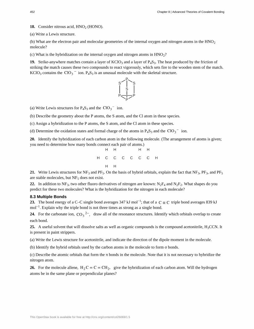
18. Consider nitrous acid, HNO2 (HONO).
(a) Write a Lewis structure.
(b) What are the electron pair and molecular geometries of the internal oxygen and nitrogen atoms in the HNO2
molecule?
(c) What is the hybridization on the internal oxygen and nitrogen atoms in HNO2?
19. Strike-anywhere matches contain a layer of KClO3 and a layer of P4S3. The heat produced by the friction ofstriking the match causes these two compounds to react vigorously, which sets fire to the wooden stem of the match.KClO3 contains the ClO3
− ion. P4S3 is an unusual molecule with the skeletal structure.
(a) Write Lewis structures for P4S3 and the ClO3– ion.
(b) Describe the geometry about the P atoms, the S atom, and the Cl atom in these species.
(c) Assign a hybridization to the P atoms, the S atom, and the Cl atom in these species.
(d) Determine the oxidation states and formal charge of the atoms in P4S3 and the ClO3– ion.
20. Identify the hybridization of each carbon atom in the following molecule. (The arrangement of atoms is given;you need to determine how many bonds connect each pair of atoms.)
21. Write Lewis structures for NF3 and PF5. On the basis of hybrid orbitals, explain the fact that NF3, PF3, and PF5
are stable molecules, but NF5 does not exist.
22. In addition to NF3, two other fluoro derivatives of nitrogen are known: N2F4 and N2F2. What shapes do youpredict for these two molecules? What is the hybridization for the nitrogen in each molecule?
8.3 Multiple Bonds23. The bond energy of a C–C single bond averages 347 kJ mol−1; that of a C ≡ C triple bond averages 839 kJmol−1. Explain why the triple bond is not three times as strong as a single bond.
24. For the carbonate ion, CO32−, draw all of the resonance structures. Identify which orbitals overlap to create
each bond.
25. A useful solvent that will dissolve salts as well as organic compounds is the compound acetonitrile, H3CCN. Itis present in paint strippers.
(a) Write the Lewis structure for acetonitrile, and indicate the direction of the dipole moment in the molecule.
(b) Identify the hybrid orbitals used by the carbon atoms in the molecule to form σ bonds.
(c) Describe the atomic orbitals that form the π bonds in the molecule. Note that it is not necessary to hybridize thenitrogen atom.
26. For the molecule allene, H2 C = C = CH2, give the hybridization of each carbon atom. Will the hydrogen
atoms be in the same plane or perpendicular planes?
452 Chapter 8 | Advanced Theories of Covalent Bonding
This OpenStax book is available for free at http://cnx.org/content/col26069/1.5

27. Identify the hybridization of the central atom in each of the following molecules and ions that contain multiplebonds:
(a) ClNO (N is the central atom)
(b) CS2
(c) Cl2CO (C is the central atom)
(d) Cl2SO (S is the central atom)
(e) SO2F2 (S is the central atom)
(f) XeO2F2 (Xe is the central atom)
(g) ClOF2+ (Cl is the central atom)
28. Describe the molecular geometry and hybridization of the N, P, or S atoms in each of the followingcompounds.
(a) H3PO4, phosphoric acid, used in cola soft drinks
(b) NH4NO3, ammonium nitrate, a fertilizer and explosive
(c) S2Cl2, disulfur dichloride, used in vulcanizing rubber
(d) K4[O3POPO3], potassium pyrophosphate, an ingredient in some toothpastes
29. For each of the following molecules, indicate the hybridization requested and whether or not the electrons willbe delocalized:
(a) ozone (O3) central O hybridization
(b) carbon dioxide (CO2) central C hybridization
(c) nitrogen dioxide (NO2) central N hybridization
(d) phosphate ion (PO43−) central P hybridization
30. For each of the following structures, determine the hybridization requested and whether the electrons will bedelocalized:
(a) Hybridization of each carbon
(b) Hybridization of sulfur
(c) All atoms
31. Draw the orbital diagram for carbon in CO2 showing how many carbon atom electrons are in each orbital.
Chapter 8 | Advanced Theories of Covalent Bonding 453
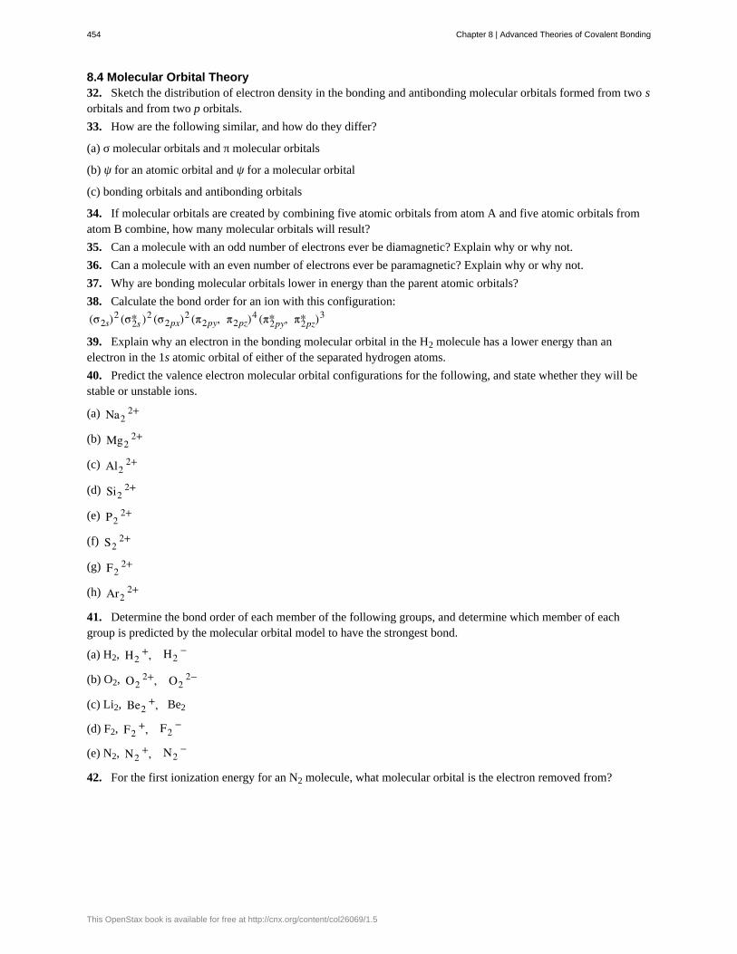
8.4 Molecular Orbital Theory32. Sketch the distribution of electron density in the bonding and antibonding molecular orbitals formed from two sorbitals and from two p orbitals.
33. How are the following similar, and how do they differ?
(a) σ molecular orbitals and π molecular orbitals
(b) ψ for an atomic orbital and ψ for a molecular orbital
(c) bonding orbitals and antibonding orbitals
34. If molecular orbitals are created by combining five atomic orbitals from atom A and five atomic orbitals fromatom B combine, how many molecular orbitals will result?
35. Can a molecule with an odd number of electrons ever be diamagnetic? Explain why or why not.
36. Can a molecule with an even number of electrons ever be paramagnetic? Explain why or why not.
37. Why are bonding molecular orbitals lower in energy than the parent atomic orbitals?
38. Calculate the bond order for an ion with this configuration:
(σ2s)2 (σ2s* )2 (σ2px)
2 (π2py, π2pz)4 (π2py* , π2pz* )3
39. Explain why an electron in the bonding molecular orbital in the H2 molecule has a lower energy than anelectron in the 1s atomic orbital of either of the separated hydrogen atoms.
40. Predict the valence electron molecular orbital configurations for the following, and state whether they will bestable or unstable ions.
(a) Na22+
(b) Mg22+
(c) Al22+
(d) Si22+
(e) P22+
(f) S22+
(g) F22+
(h) Ar22+
41. Determine the bond order of each member of the following groups, and determine which member of eachgroup is predicted by the molecular orbital model to have the strongest bond.
(a) H2, H2+, H2
−
(b) O2, O22+, O2
2−
(c) Li2, Be2+, Be2
(d) F2, F2+, F2
−
(e) N2, N2+, N2
−
42. For the first ionization energy for an N2 molecule, what molecular orbital is the electron removed from?
454 Chapter 8 | Advanced Theories of Covalent Bonding
This OpenStax book is available for free at http://cnx.org/content/col26069/1.5

43. Compare the atomic and molecular orbital diagrams to identify the member of each of the following pairs thathas the highest first ionization energy (the most tightly bound electron) in the gas phase:
(a) H and H2
(b) N and N2
(c) O and O2
(d) C and C2
(e) B and B2
44. Which of the period 2 homonuclear diatomic molecules are predicted to be paramagnetic?
45. A friend tells you that the 2s orbital for fluorine starts off at a much lower energy than the 2s orbital for lithium,so the resulting σ2s molecular orbital in F2 is more stable than in Li2. Do you agree?
46. True or false: Boron contains 2s22p1 valence electrons, so only one p orbital is needed to form molecularorbitals.
47. What charge would be needed on F2 to generate an ion with a bond order of 2?
48. Predict whether the MO diagram for S2 would show s-p mixing or not.
49. Explain why N22+ is diamagnetic, while O2
4+, which has the same number of valence electrons, is
paramagnetic.
50. Using the MO diagrams, predict the bond order for the stronger bond in each pair:
(a) B2 or B2+
(b) F2 or F2+
(c) O2 or O22+
(d) C2+ or C2
−
Chapter 8 | Advanced Theories of Covalent Bonding 455

456 Chapter 8 | Advanced Theories of Covalent Bonding
This OpenStax book is available for free at http://cnx.org/content/col26069/1.5