Chapter 8
125
Chapter 8 Pipelining
-
Upload
mona-deleon -
Category
Documents
-
view
38 -
download
0
description
Chapter 8. Pipelining. Pipelining. A strategy for employing parallelism to achieve better performance Taking the “assembly line” approach to fetching and executing instructions. The Cycle. The control unit: Fetch Execute Fetch Execute Etc. Etc. The Cycle. - PowerPoint PPT Presentation
Transcript of Chapter 8
Chapter 8
Pipelining

Pipelining
• A strategy for employing parallelism to achieve better performance
• Taking the “assembly line” approach to fetching and executing instructions

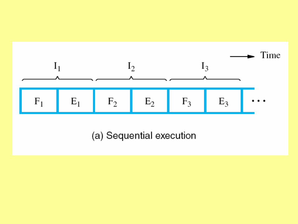
The Cycle
The control unit:
Fetch
Execute
Fetch
Execute
Etc.
Etc.
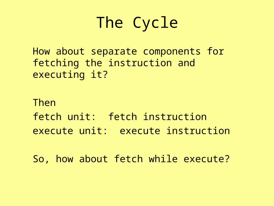
The Cycle
How about separate components for fetching the instruction and executing it?
Then
fetch unit: fetch instruction
execute unit: execute instruction
So, how about fetch while execute?
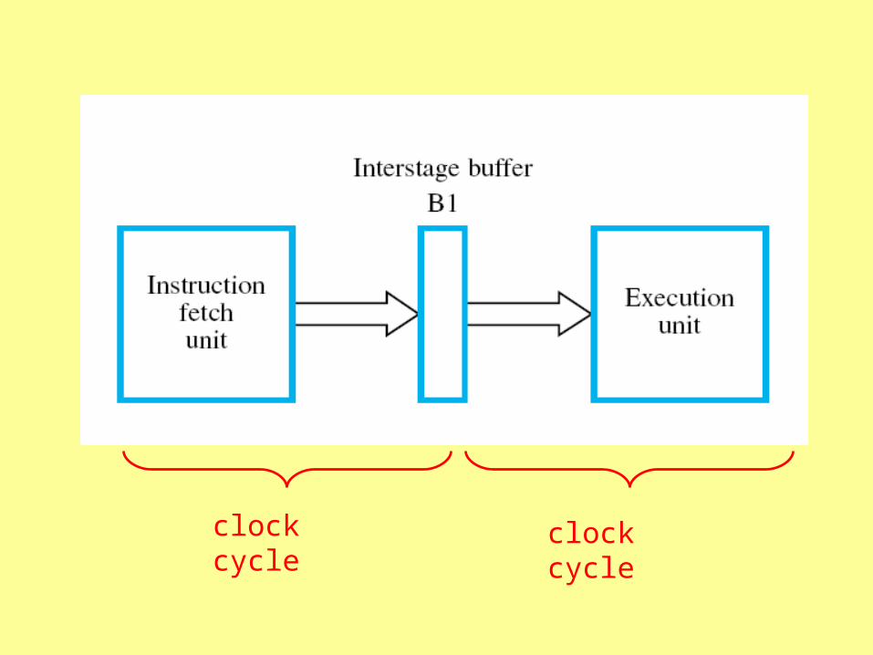
clock cycle clock cycle
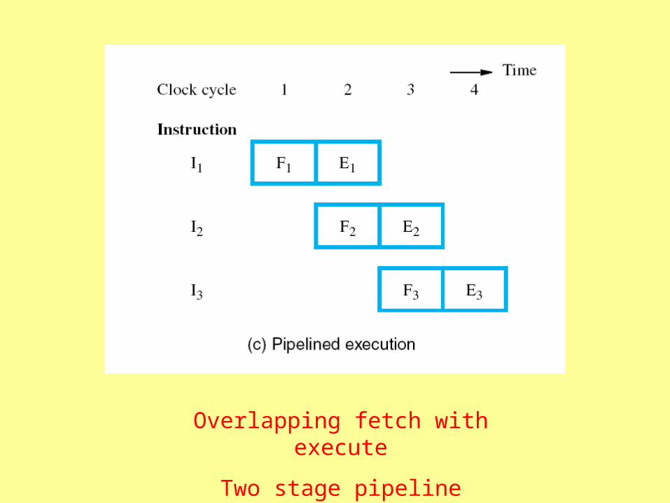
Overlapping fetch with execute
Two stage pipeline
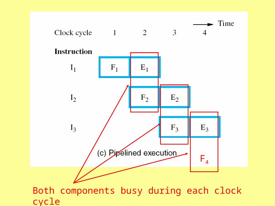
Both components busy during each clock cycle
F4

The Cycle
The cycle can be divided into four parts
fetch instruction
decode instruction
execute instruction
write result back to memory
So, how about four components?
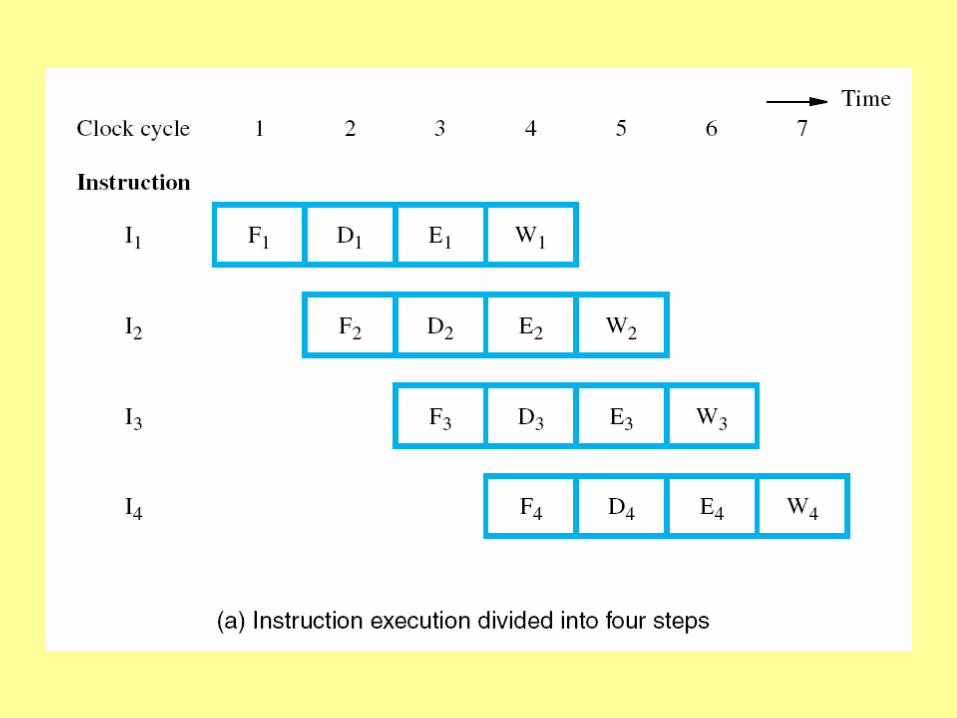
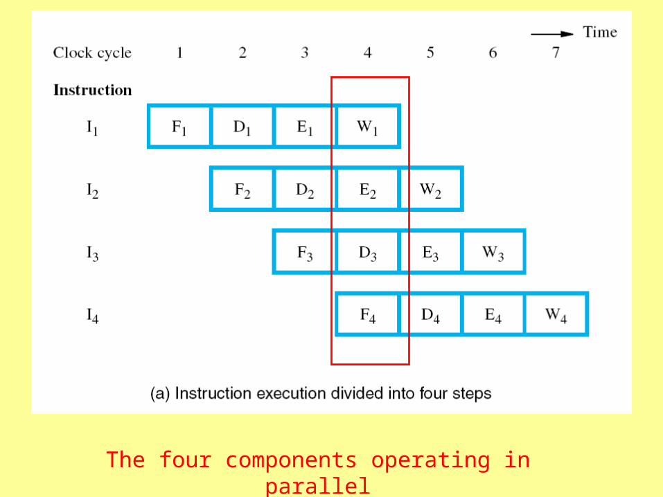
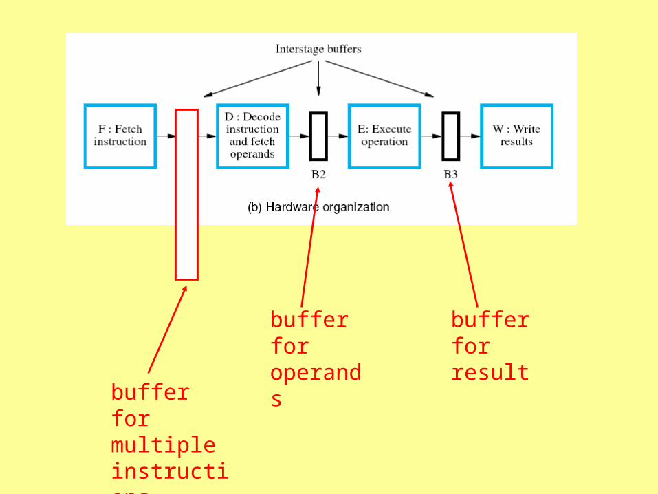
The four components operating in parallel
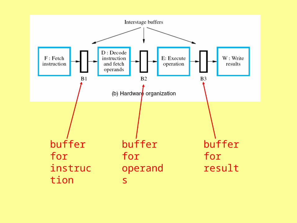
buffer for instruction
buffer for operands
buffer for result
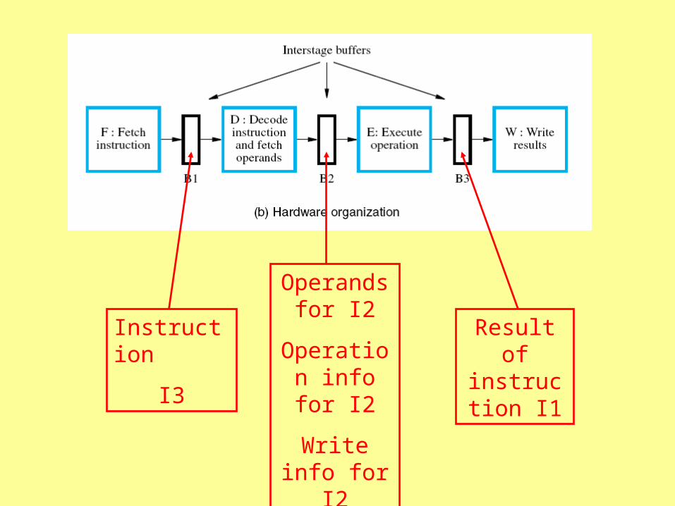
Instruction
I3
Operands for I2
Operation info for I2
Write info for I2
Result of instruction
I1

One clock cycle for each pipeline stage
Therefore cycle time must be long enough for the longest stage
A unit is idle if it requires less time than another
Best if all stages are about the same length
Cache memory helps
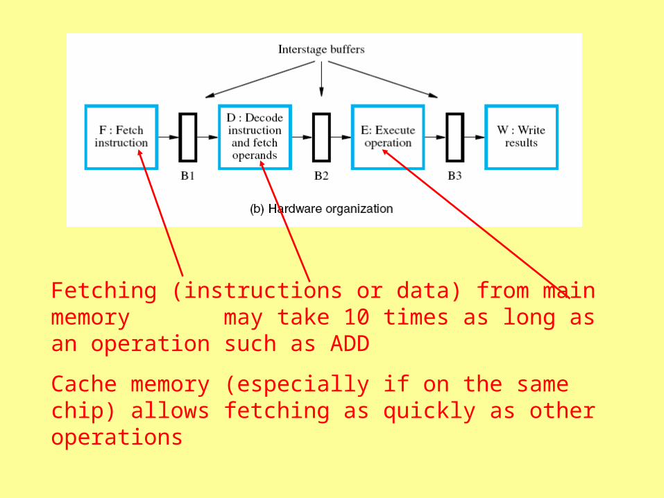
Fetching (instructions or data) from main memory may take 10 times as long as an operation such as ADD
Cache memory (especially if on the same chip) allows fetching as quickly as other operations
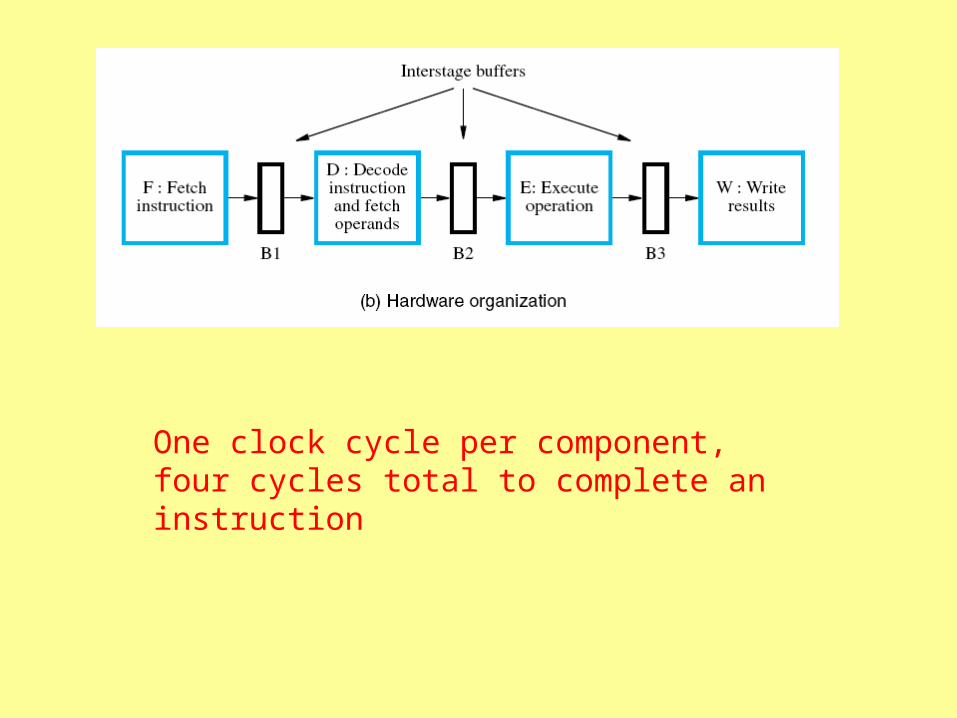
One clock cycle per component, four cycles total to complete an instruction
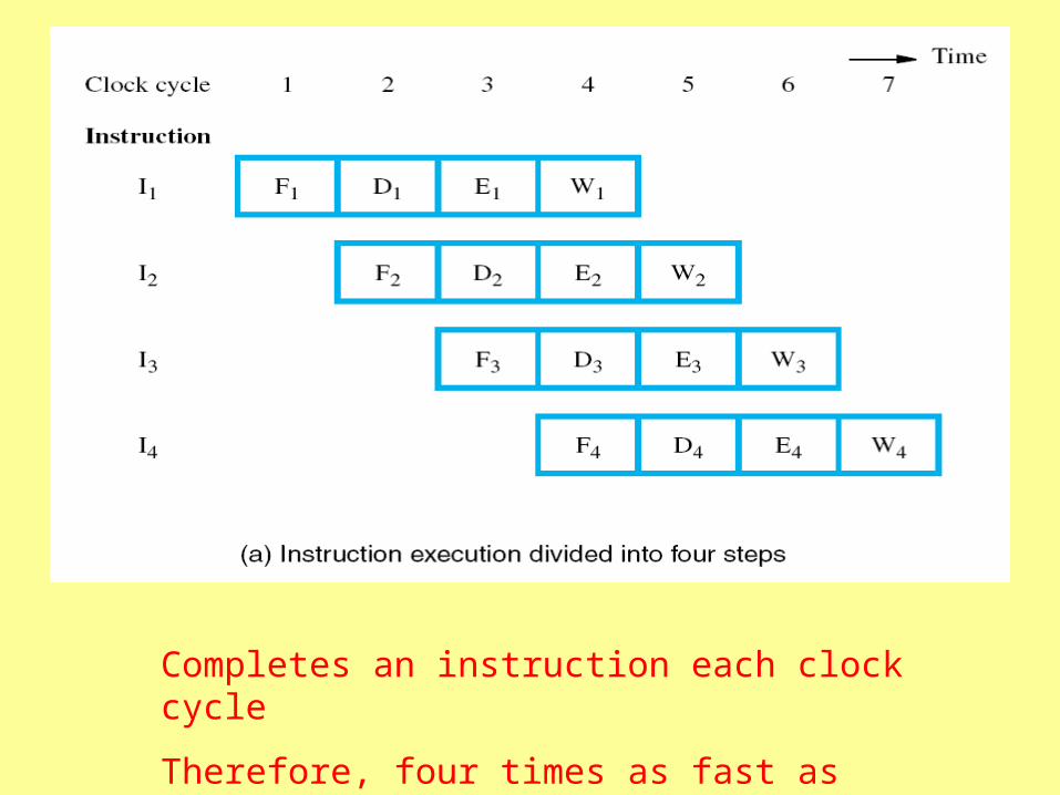
Completes an instruction each clock cycle
Therefore, four times as fast as without pipeline
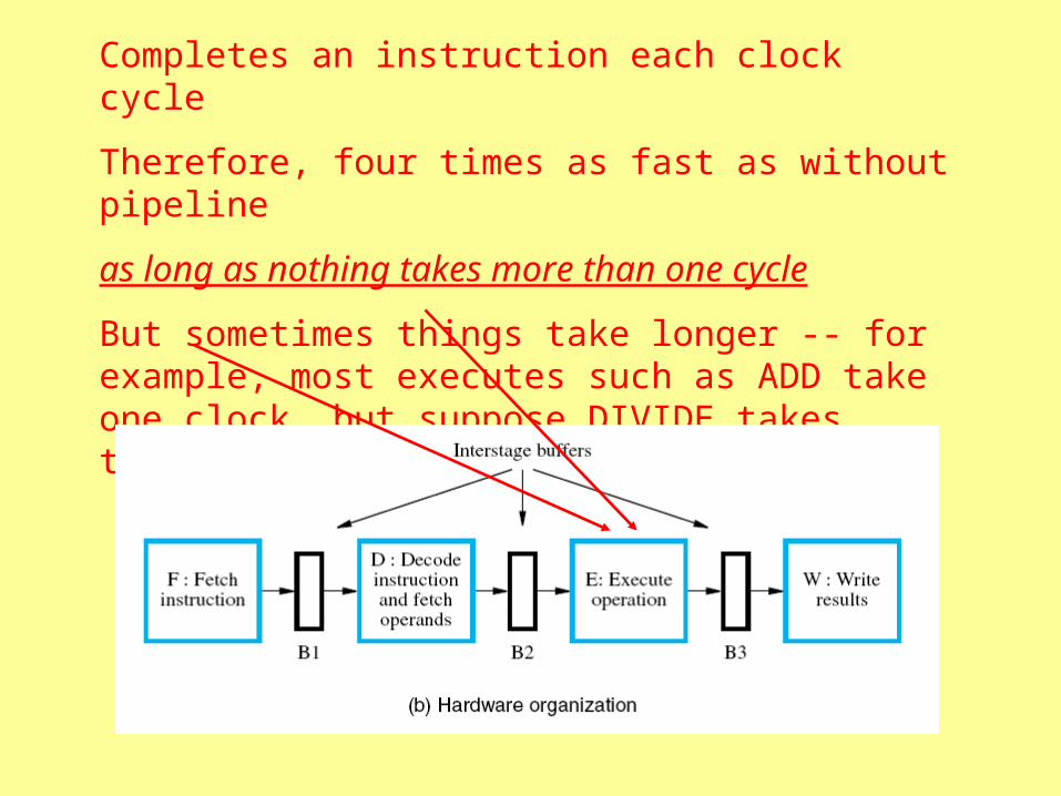
Completes an instruction each clock cycle
Therefore, four times as fast as without pipeline
as long as nothing takes more than one cycle
But sometimes things take longer -- for example, most executes such as ADD take one clock, but suppose DIVIDE takes three
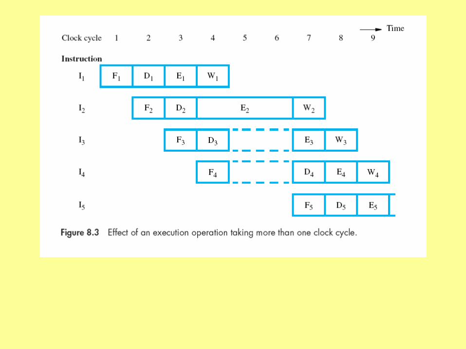
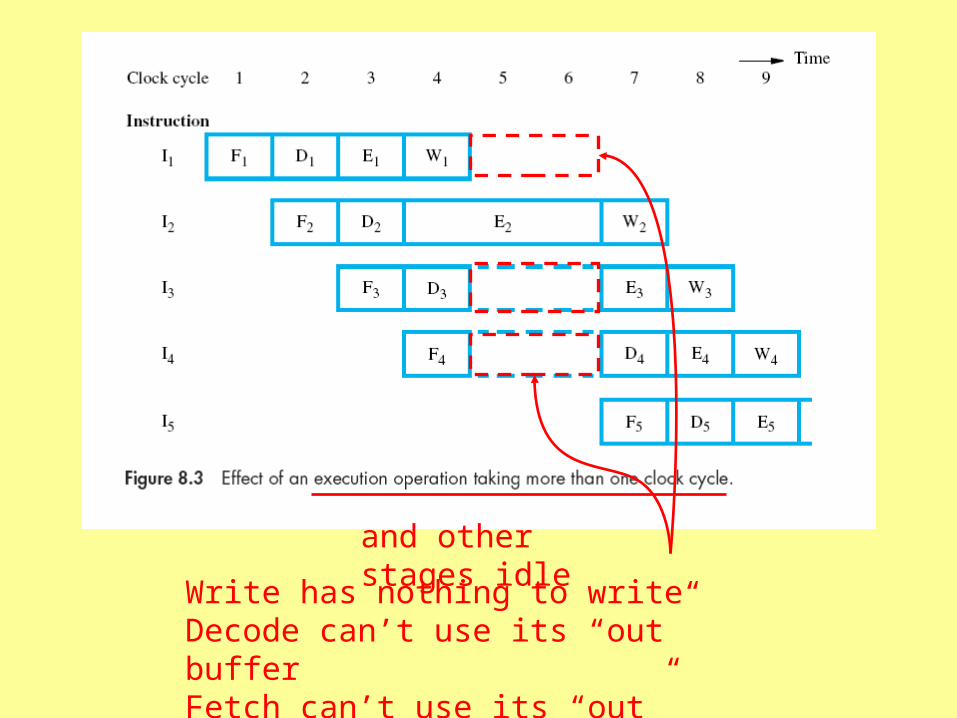
and other stages idle
Write has nothing to writeDecode can’t use its “out” bufferFetch can’t use its “out” buffer
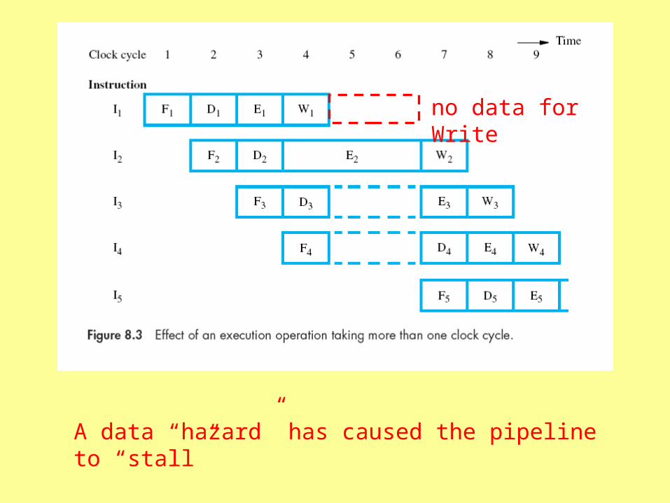
A data “hazard” has caused the pipeline to “stall”
no data for Write
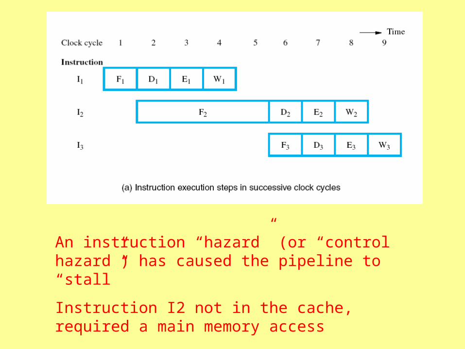
An instruction “hazard” (or “control hazard”) has caused the pipeline to “stall”
Instruction I2 not in the cache, required a main memory access

Structural Hazards
• Conflict over use of a hardware resource
• Memory – Can’t fetch an instruction while another instruction is
fetching an operand, for example
– Cache: same• Unless cache has multiple ports• Or separate caches for instructions, data
• Register file• One access at a time, again unless multiple ports
Structural Hazards
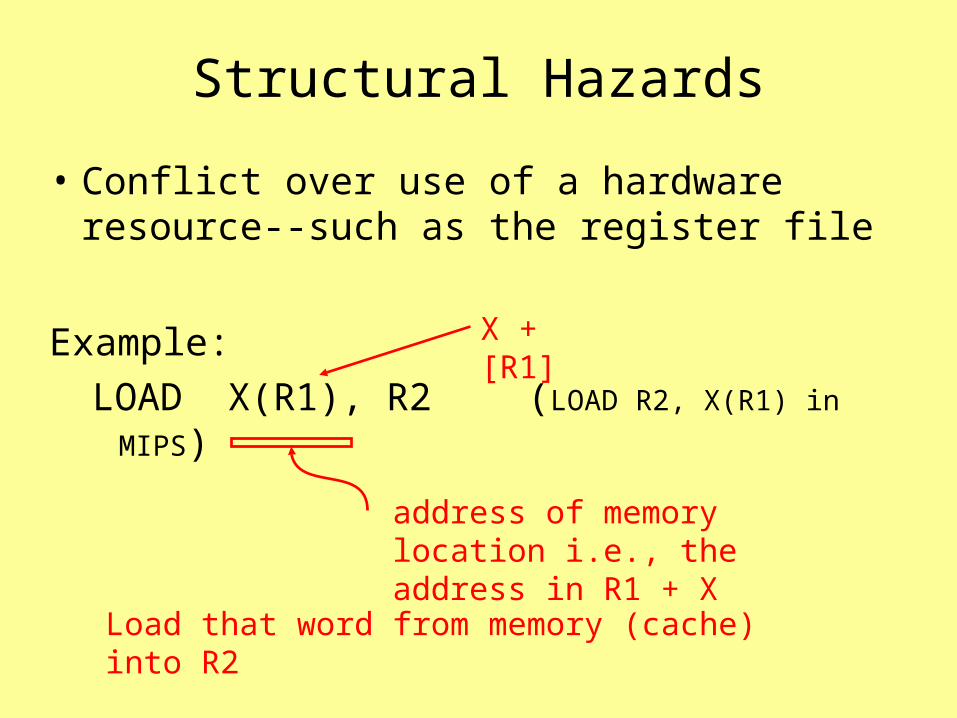
• Conflict over use of a hardware resource--such as the register file
Example:
LOAD X(R1), R2 (LOAD R2, X(R1) in
MIPS)address of memory location i.e., the address in R1 + X
Load that word from memory (cache) into R2
X + [R1]

I2 writing to register file
I3 must wait for register file
I2 takes extra cycle for cache access as part of execution
calculate the address
I5 fetch delayed

Data Hazards
• Situations that cause the pipeline to stall because data to be operated on is delayed– execute takes extra cycle, for example

Data Hazards
• Or, because of data dependencies
– Pipeline stalls because an instruction depends on data from another instruction
Concurrency
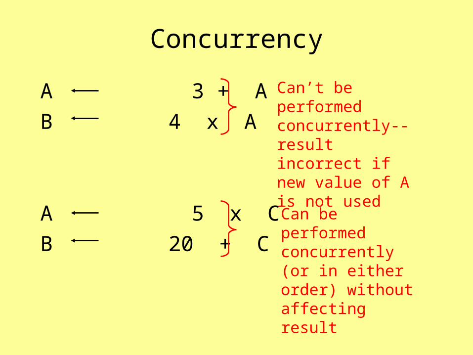
A 3 + A
B 4 x A
A 5 x C
B 20 + C
Can’t be performed concurrently--result incorrect if new value of A is not used
Can be performed concurrently (or in either order) without affecting result
Concurrency
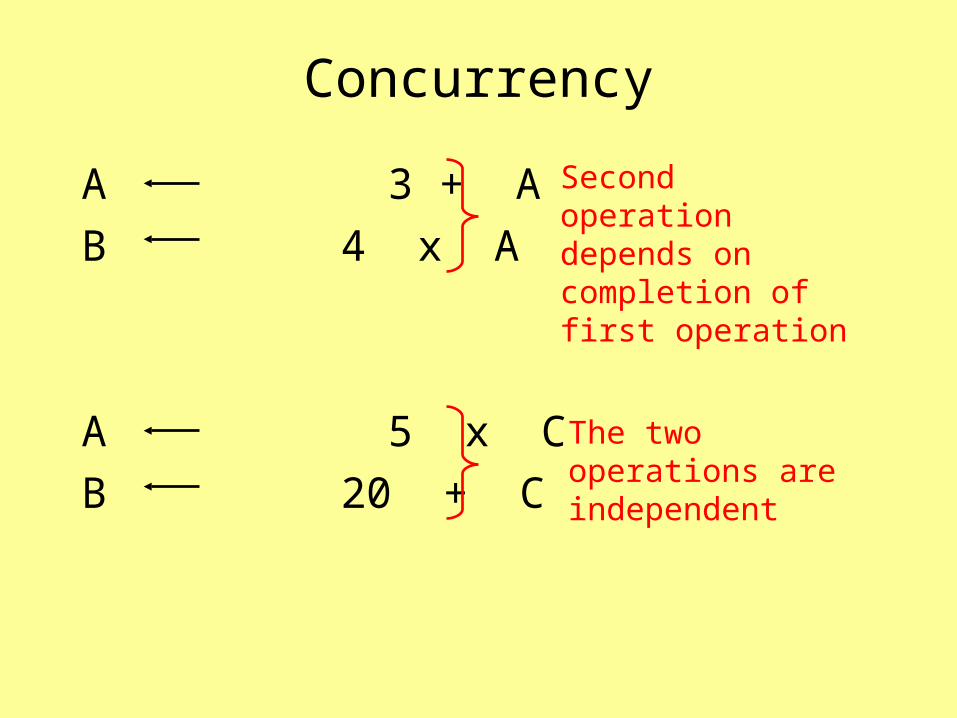
A 3 + A
B 4 x A
A 5 x C
B 20 + C
Second operation depends on completion of first operation
The two operations are independent
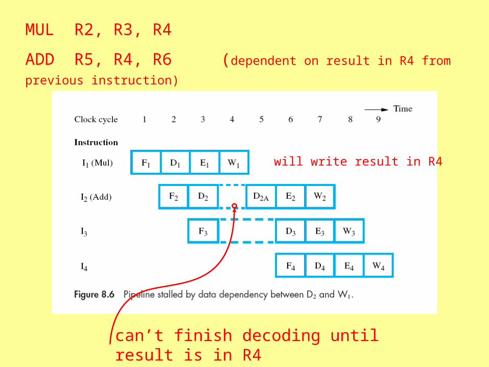
MUL R2, R3, R4
ADD R5, R4, R6 (dependent on result in R4 from previous instruction)
will write result in R4
can’t finish decoding until result is in R4
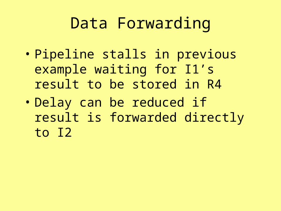
Data Forwarding
• Pipeline stalls in previous example waiting for I1’s result to be stored in R4
• Delay can be reduced if result is forwarded directly to I2
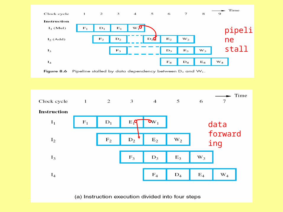
pipeline stall
data forwarding
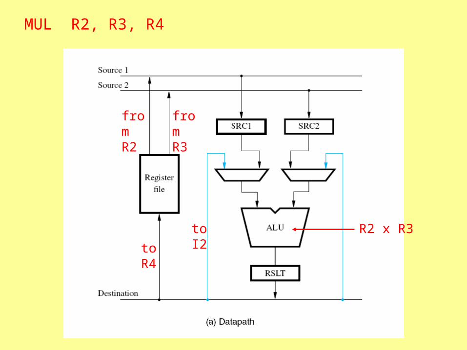
MUL R2, R3, R4
from R2
R2 x R3
toR4
to I2
from R3

ADD R5, R4, R6
MUL R2, R3, R4
R2, R3
R2 x R3
R2 x R3
R2 x R3
R5 R4 + R5
R4
R6

If solved by software:
MUL R2, R3, R4
NOOP
NOOP
ADD R5, R4, R6
2 cycle stall introduced by hardware
(if no data forwarding)
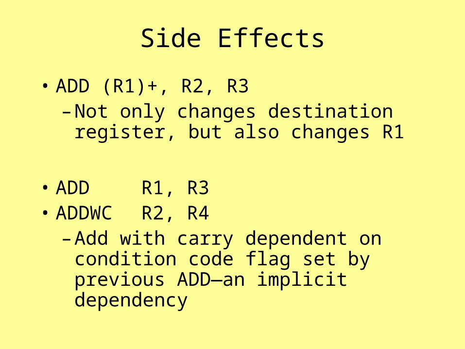
Side Effects
• ADD (R1)+, R2, R3– Not only changes destination register,
but also changes R1
• ADD R1, R3• ADDWC R2, R4
– Add with carry dependent on condition code flag set by previous ADD—an implicit dependency

Side Effects
• Data dependency on something other than the result destination
• Multiple dependencies
• Pipelining clearly works better if side effects are avoided in the instruction set
– Simple instructions

Instruction Hazards
• Pipeline depends on steady stream of instructions from the instruction fetch unit
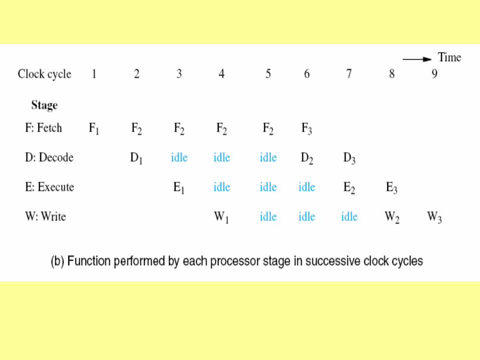
pipeline stall from a cache miss
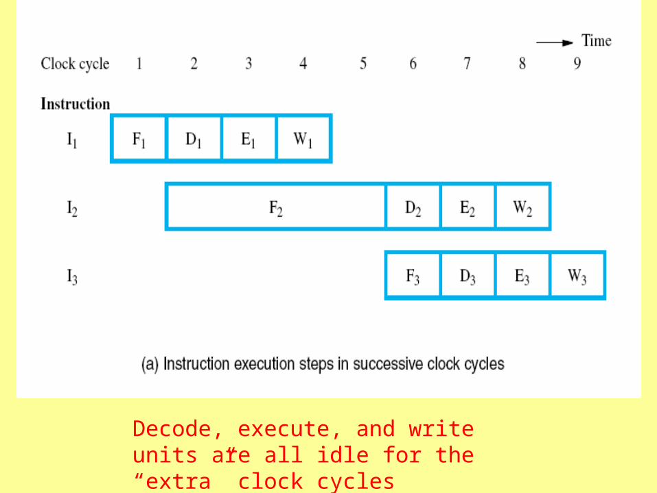
Decode, execute, and write units are all idle for the “extra” clock cycles
Branch Instructions
• Their purpose is to change the content of the PC and fetch another instruction
• Consequently, the fetch unit may be fetching an “unwanted” instruction

SW R1, A
BUN K
LW R5, B
two stage pipeline
fetch instruction 3
discard instruction 3 and fetch instruction K instead
computes new PC value
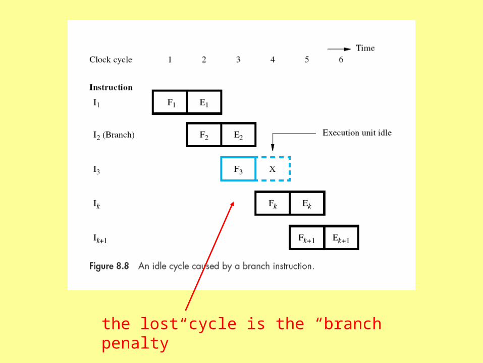
the lost cycle is the “branch penalty”
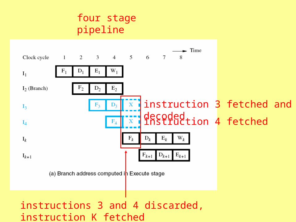
four stage pipeline
instruction 3 fetched and decoded
instruction 4 fetched
instructions 3 and 4 discarded, instruction K fetched
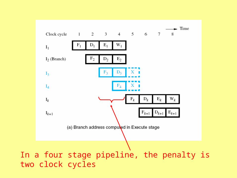
In a four stage pipeline, the penalty is two clock cycles
Unconditional Branch Instructions
• Reducing the branch penalty requires computing the branch address earlier
• Hardware in the fetch and decode units
– Identify branch instructions
– Compute branch target address
(instead of doing it in the execute stage)
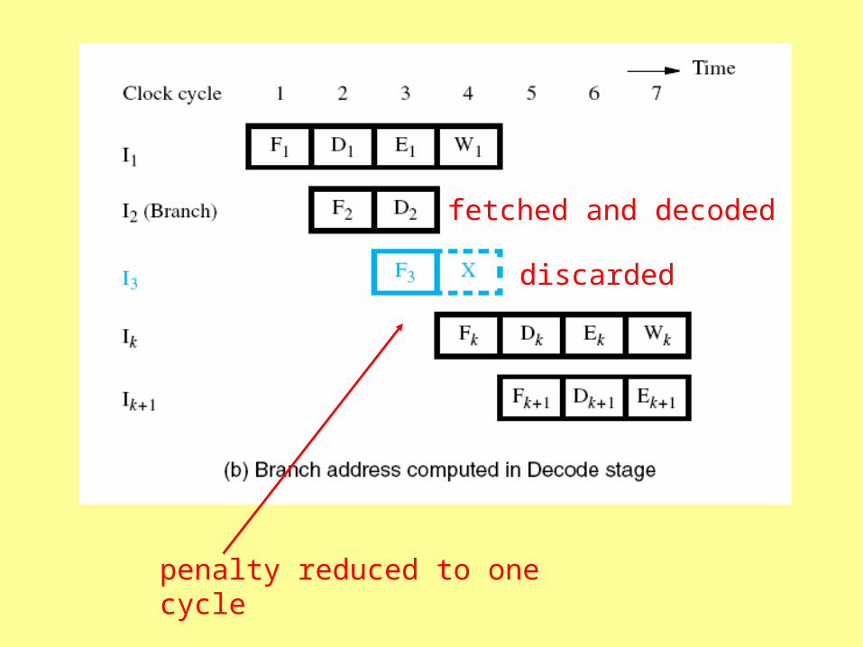
fetched and decoded
discarded
penalty reduced to one cycle
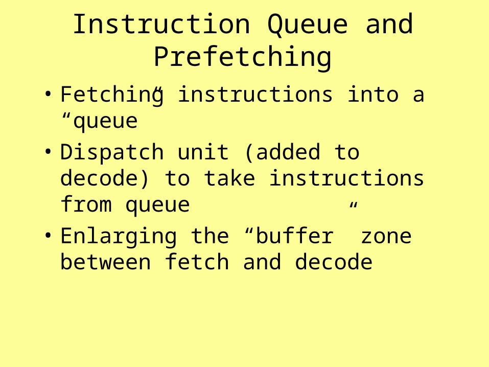
Instruction Queue and Prefetching
• Fetching instructions into a “queue”
• Dispatch unit (added to decode) to take instructions from queue
• Enlarging the “buffer” zone between fetch and decode

buffer for instruction
buffer for operands
buffer for result
buffer for multiple instructions
buffer for operands
buffer for result
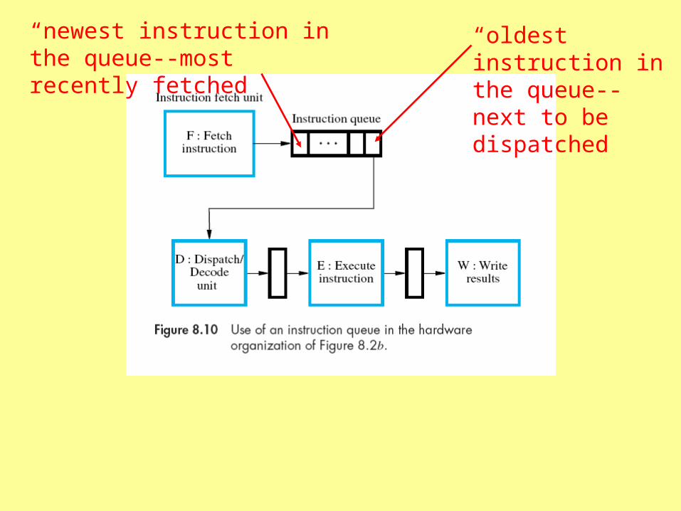
“oldest instruction in the queue--next to be dispatched
“newest instruction in the queue--most recently fetched
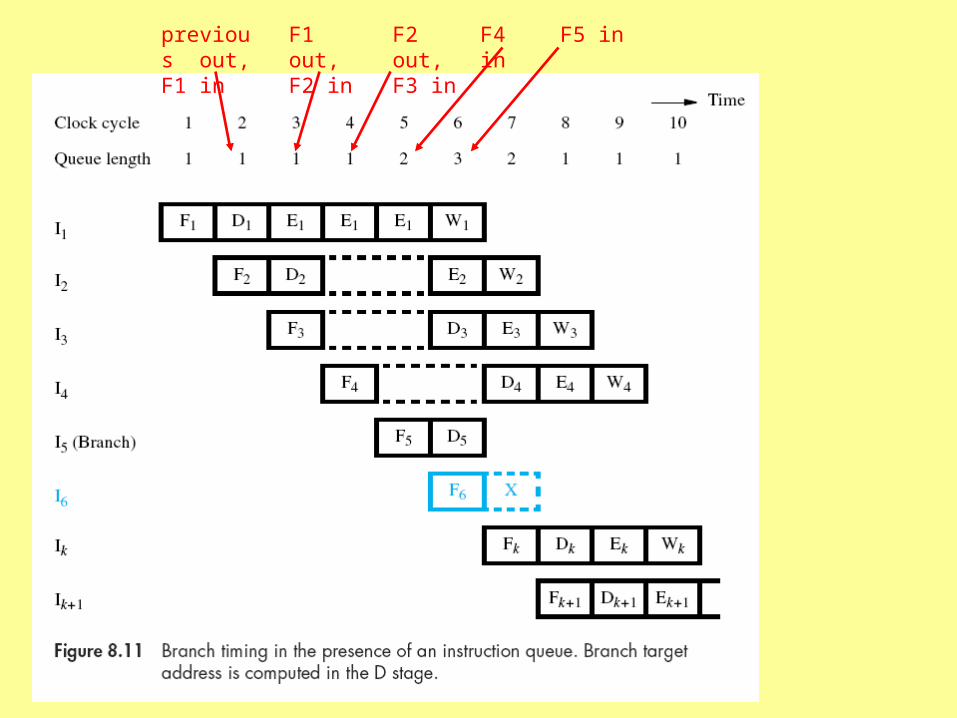
previous out, F1 in
F1 out, F2 in
F2 out, F3 in
F4 in F5 in
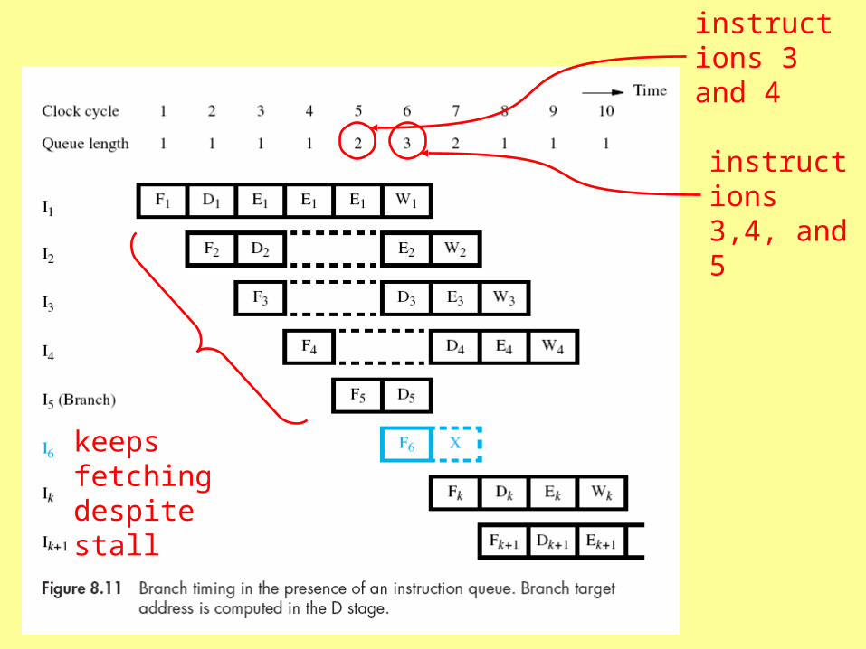
instructions 3 and 4
instructions 3,4, and 5
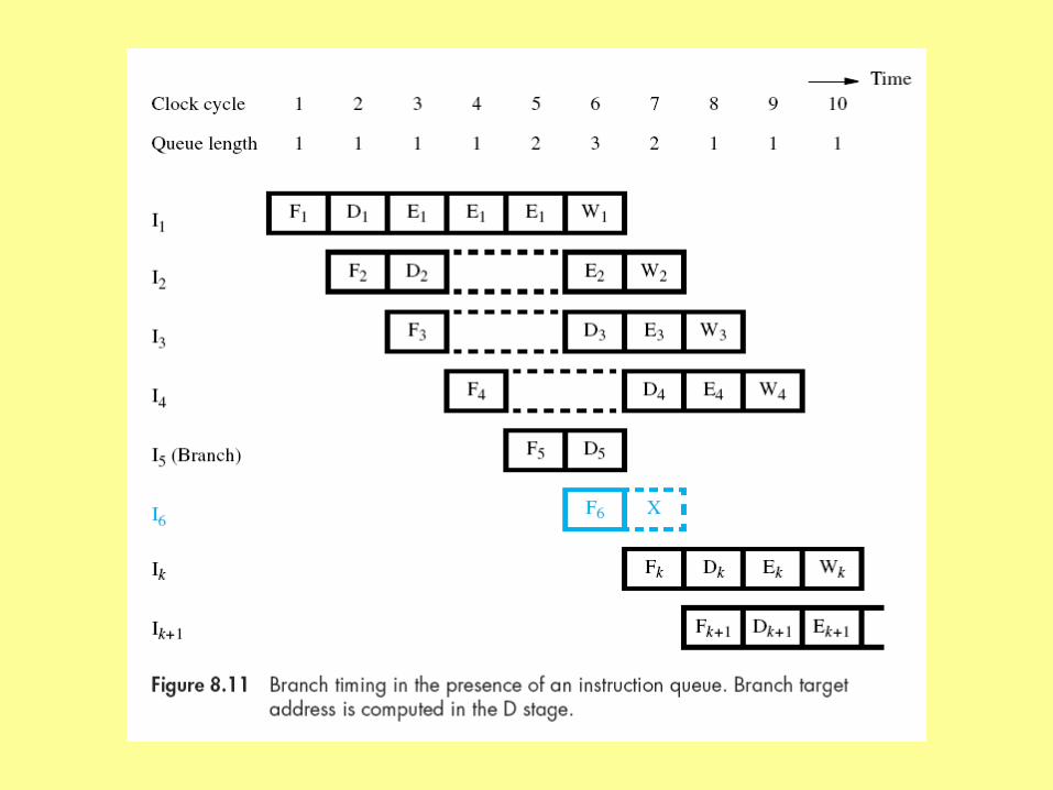
keeps fetching despite stall
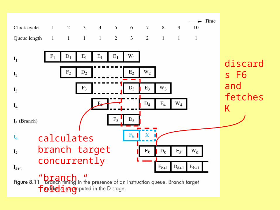
calculates branch target concurrently
“branch folding”
discards F6 and fetches K

completes an instruction each clock cycle
no branch penalty

Instruction Queue
• Avoiding branch penalty requires that the queue contain other instructions for processing while branch target is calculated
• Queue can mitigate cache misses--if instruction not in cache, execution unit can continue as long as queue has instructions
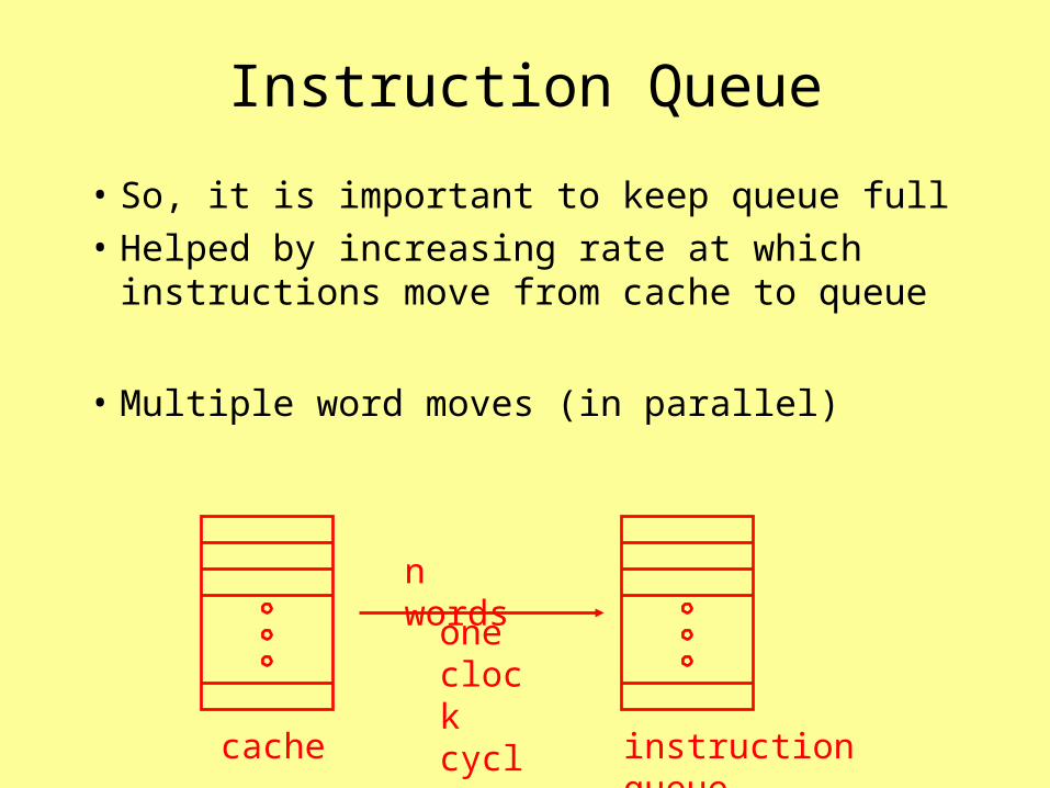
Instruction Queue
• So, it is important to keep queue full
• Helped by increasing rate at which instructions move from cache to queue
• Multiple word moves (in parallel)
cache instruction queue
one clock cycle
n words

Conditional Branching
• Added hazard of dependency on previous instruction
• Can’t calculate target until a previous instruction completes execution
SUBW R1, A F ED W
F D
1
2
fetch K or fetch 3?
BGTZ K
Conditional Branching
• Occur frequently, perhaps 20% of all instruction executions
• Would present serious problems for pipelining if not handled
• Several possibilities

Delayed Branching
• Location(s) following a branch instruction have been fetched and must be discarded
• These positions called “branch delay slots”
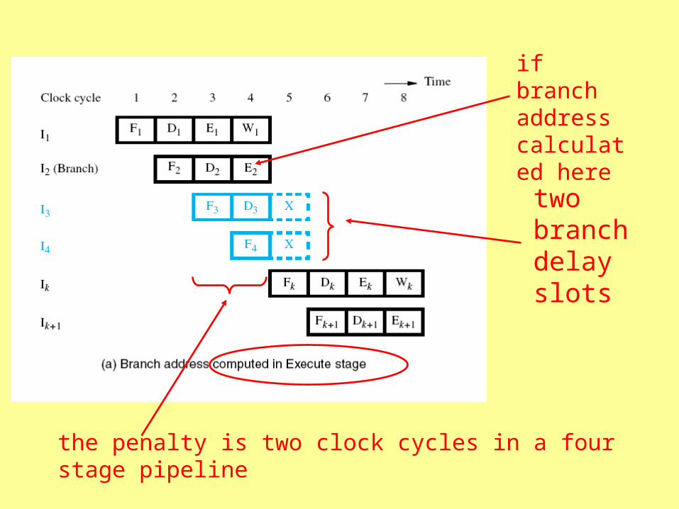
the penalty is two clock cycles in a four stage pipeline
two branch delay slots
if branch address calculated here
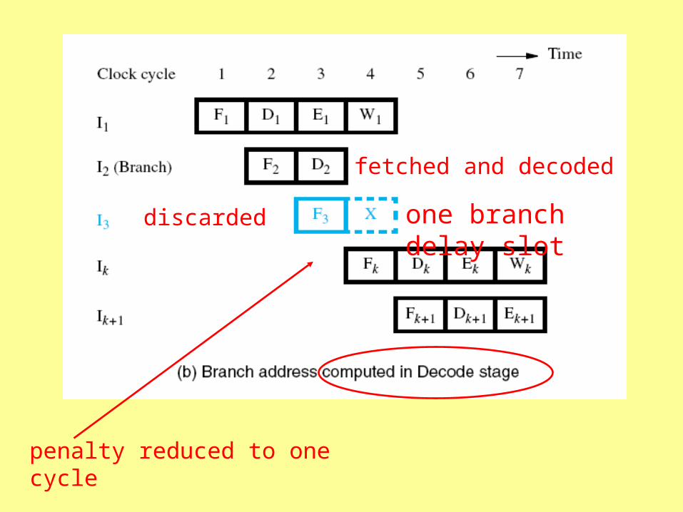
fetched and decoded
discarded
penalty reduced to one cycle
one branch delay slot
Delayed Branching
• Instructions in delay slots always fetched and partially executed
• So, place useful instructions in those positions and execute whether branch is taken or not
• If no such instructions, use NOOPs

shift R1 N times
R2 contains N
fetched and discarded on every iteration
branch if not zero
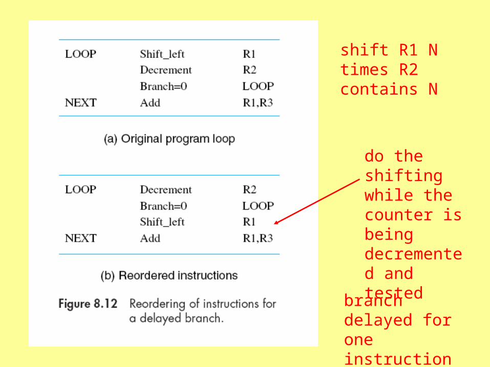
shift R1 N times R2 contains N
do the shifting while the counter is being decremented and tested
branch delayed for one instruction

appears to “branch” here
actually branches here
Branch instruction waits for an instruction cycle before actually branching—hence “delayed branch”
“delay slot”
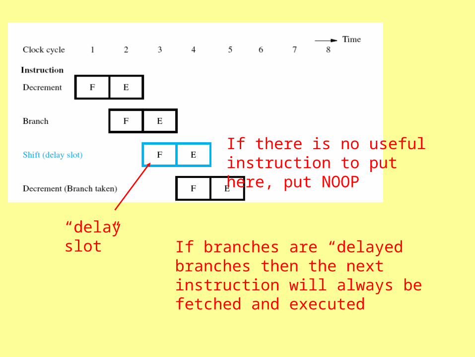
If there is no useful instruction to put here, put NOOP
“delay slot”If branches are “delayed branches then the next instruction will always be fetched and executed
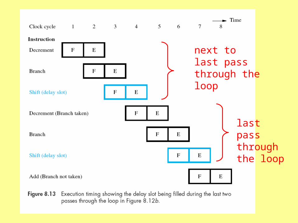
next to last pass through the loop
last pass through the loop

will branch, so fetch the decrement instruction
won’t branch, so fetch the add instruction
Delayed Branching
• Compiler must recognize and rearrange instructions
• One branch delay slot can usually be filled--filling two is much more difficult
• If adding pipeline stages increases number of branch delay slots, benefit may be lost
Branch Prediction
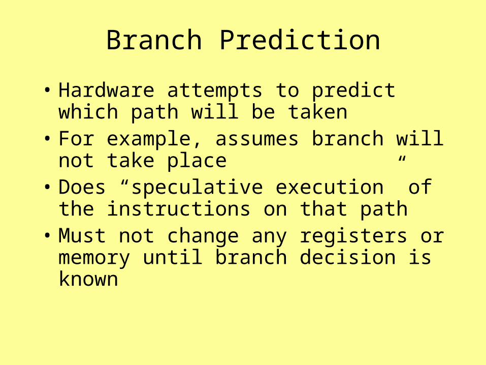
• Hardware attempts to predict which path will be taken
• For example, assumes branch will not take place
• Does “speculative execution” of the instructions on that path
• Must not change any registers or memory until branch decision is known
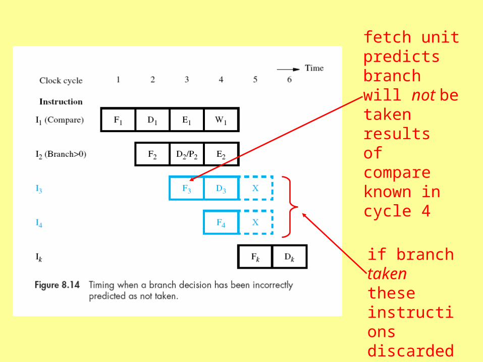
fetch unit predicts branch will not be taken
results of compare known in cycle 4
if branch taken these instructions discarded
Static Branch Prediction
• Hardware attempts to predict which path will be taken (shouldn’t always assume the same result)
• Based on target address of branch—is it higher or lower than current address
• Software (compiler) can make better prediction and for example set a bit in the branch instruction
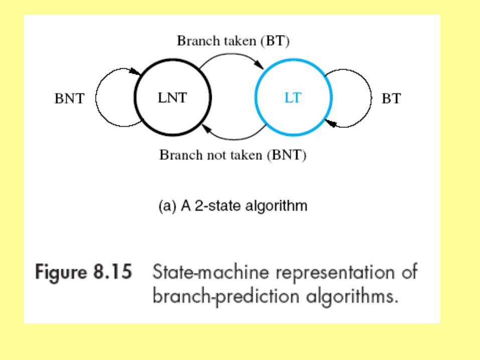
Dynamic Branch Prediction
• Processor keeps track of branch decisions
• Determines likelihood of future branches
• One bit for each branch instruction
– LT branch likely to be taken
– LNT branch likely not to be taken
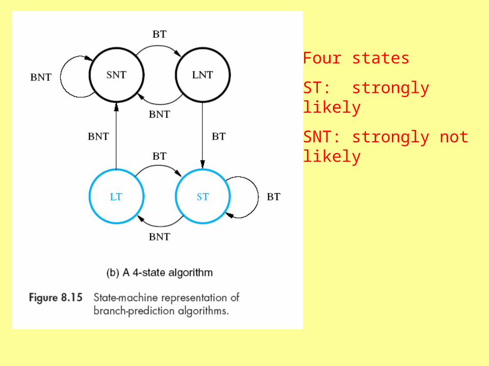
Four states
ST: strongly likely
SNT: strongly not likely
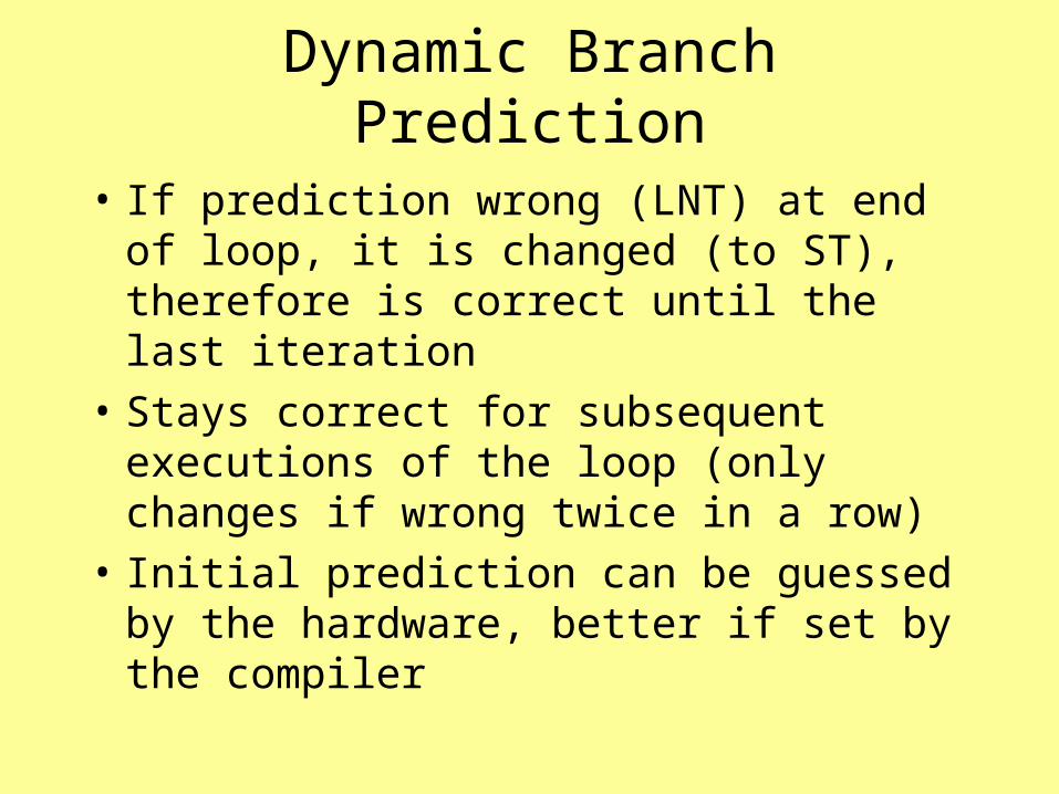
Dynamic Branch Prediction
• If prediction wrong (LNT) at end of loop, it is changed (to ST), therefore is correct until the last iteration
• Stays correct for subsequent executions of the loop (only changes if wrong twice in a row)
• Initial prediction can be guessed by the hardware, better if set by the compiler
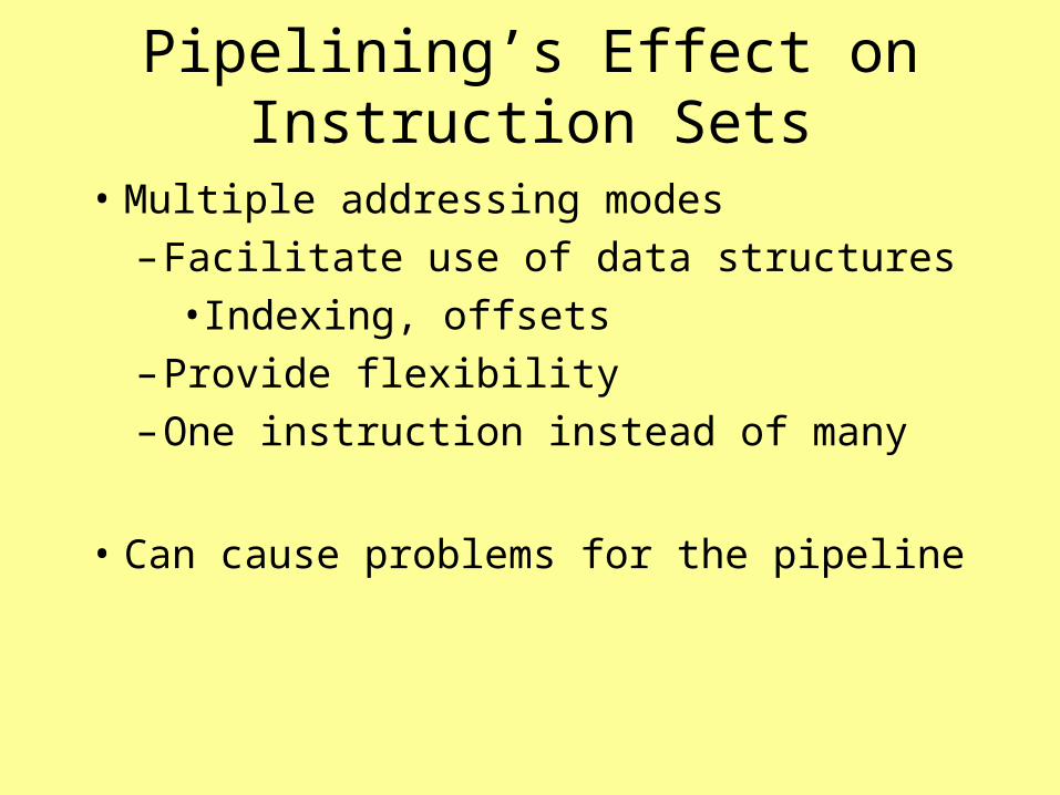
Pipelining’s Effect on Instruction Sets
• Multiple addressing modes
– Facilitate use of data structures
• Indexing, offsets
– Provide flexibility
– One instruction instead of many
• Can cause problems for the pipeline
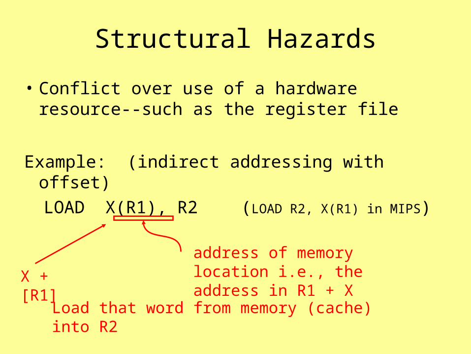
Structural Hazards
• Conflict over use of a hardware resource--such as the register file
Example: (indirect addressing with offset)
LOAD X(R1), R2 (LOAD R2, X(R1) in
MIPS)address of memory location i.e., the address in R1 + X
Load that word from memory (cache) into R2
X + [R1]

I2 writing to register file
I3 must wait for register file
I2 takes extra cycle for cache access as part of execution
calculate the address (register access)
I5 fetch delayed
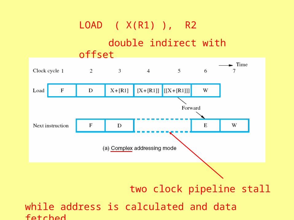
LOAD ( X(R1) ), R2
double indirect with offset
two clock pipeline stall
while address is calculated and data fetched
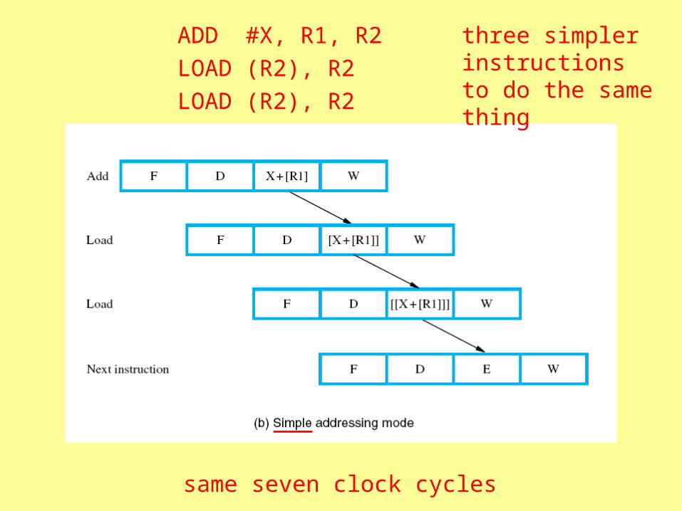
ADD #X, R1, R2
LOAD (R2), R2
LOAD (R2), R2
same seven clock cycles
three simpler instructions to do the same thing
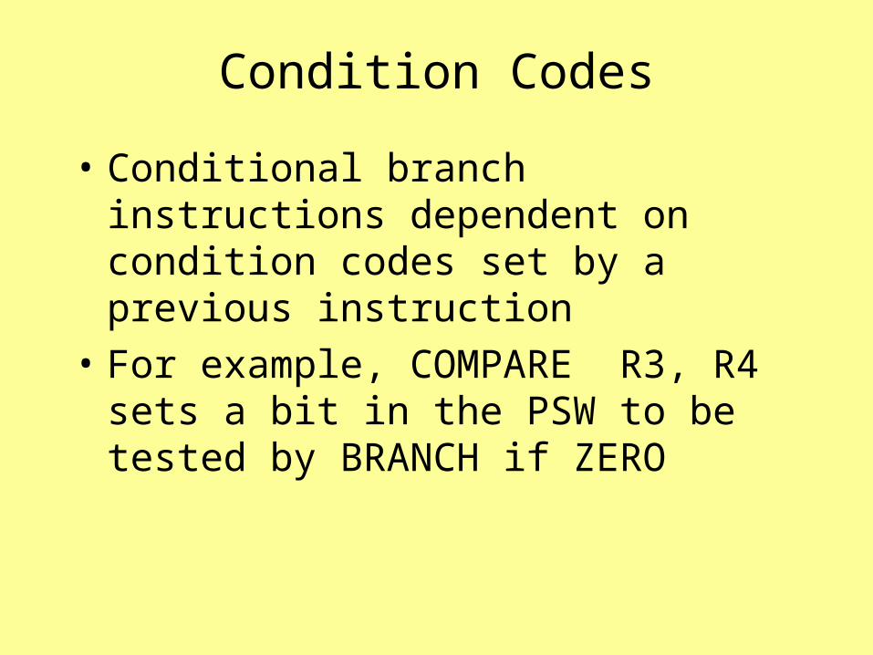
Condition Codes
• Conditional branch instructions dependent on condition codes set by a previous instruction
• For example, COMPARE R3, R4 sets a bit in the PSW to be tested by BRANCH if ZERO

Branch decision must wait for completion of Compare
Can’t take place in decode, must wait for execution stage
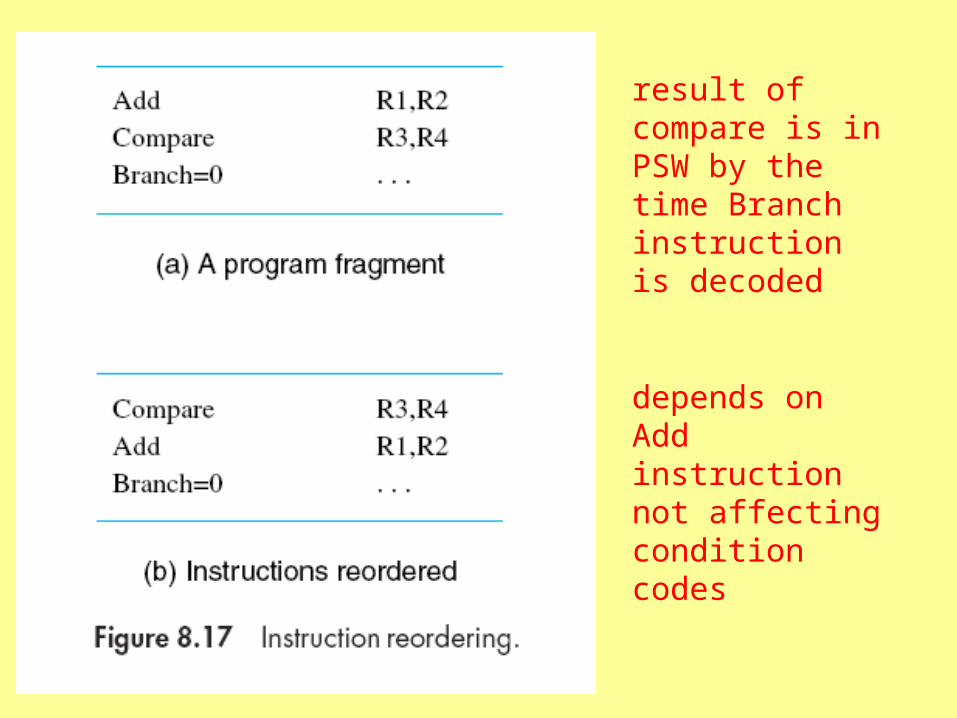
result of compare is in PSW by the time Branch instruction is decoded
depends on Add instruction not affecting condition codes

Condition Codes and Pipelining
• Compiler must be able to reorder instructions
• Condition codes set by few instructions
• Compiler should be able to control which instructions set condition codes
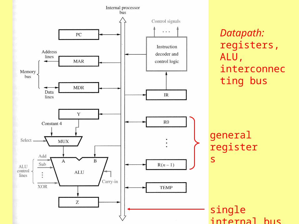
Datapath: registers, ALU, interconnecting bus
single internal bus
general registers
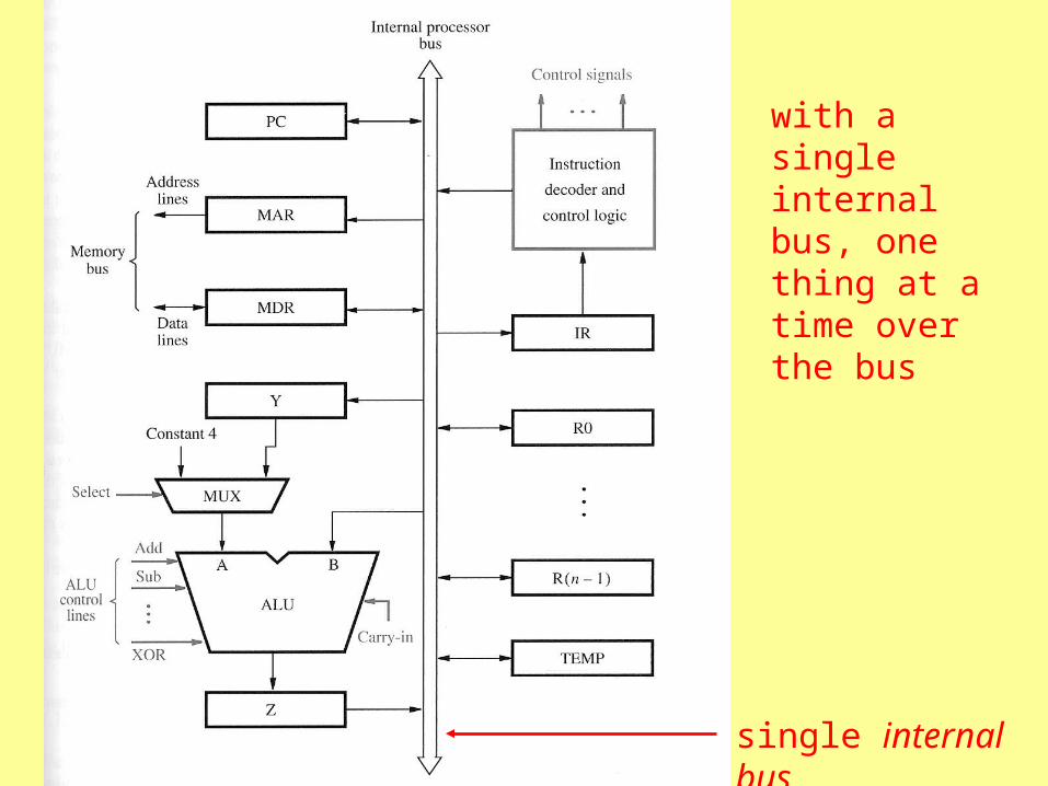
with a single internal bus, one thing at a time over the bus
single internal bus
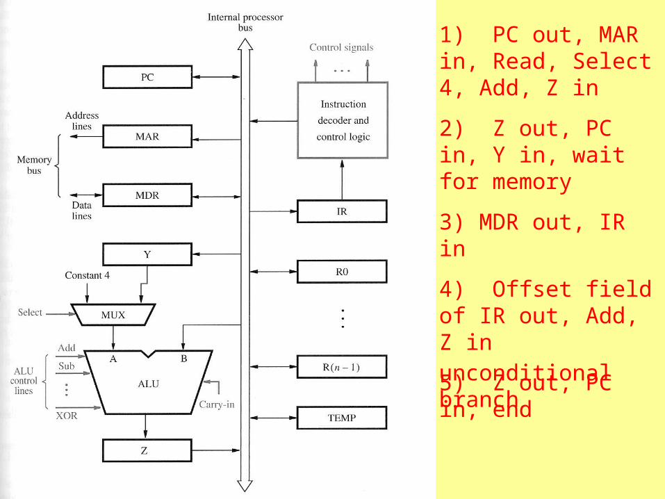
1) PC out, MAR in, Read, Select 4, Add, Z in
2) Z out, PC in, Y in, wait for memory
3) MDR out, IR in
4) Offset field of IR out, Add, Z in
5) Z out, PC in, end
unconditional branch

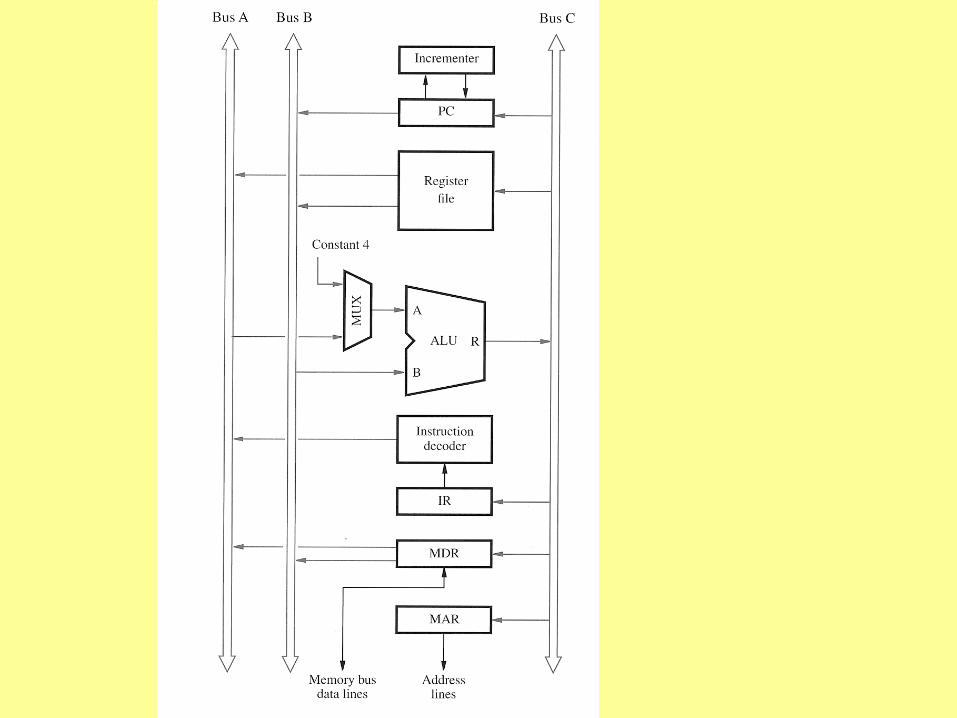
three internal buses
three port register file
transfers three at a time
PC incrementer
for address incrementing (multiple word transfers)
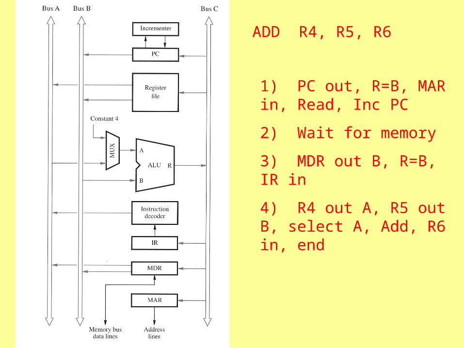
1) PC out, R=B, MAR in, Read, Inc PC
2) Wait for memory
3) MDR out B, R=B, IR in
4) R4 out A, R5 out B, select A, Add, R6 in, end
ADD R4, R5, R6
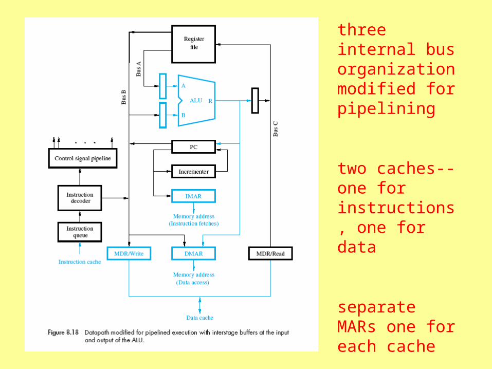
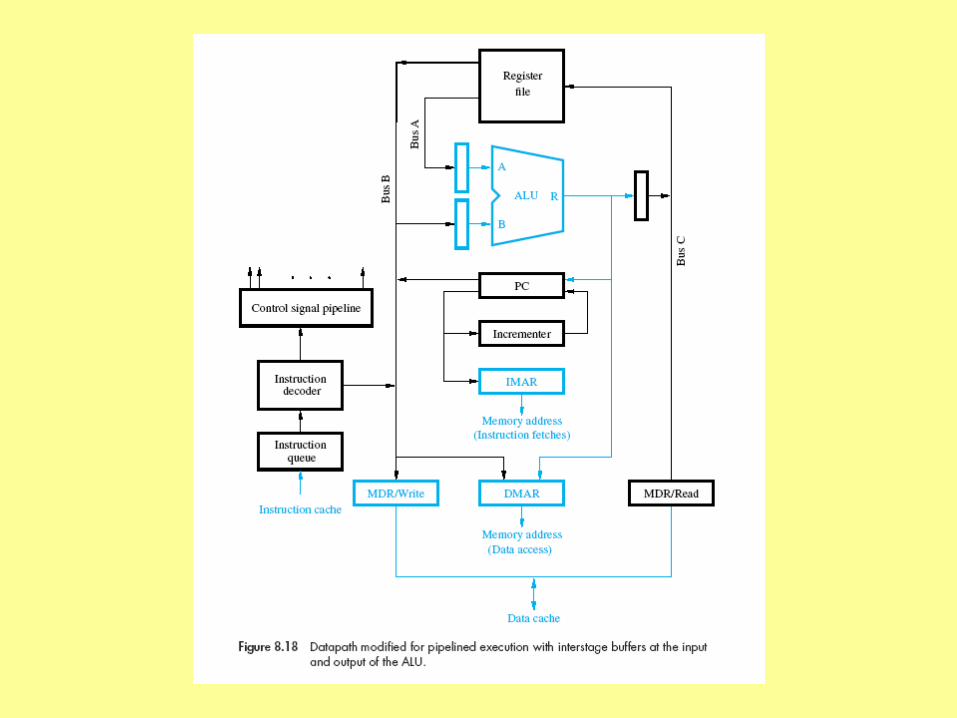
three internal bus organization modified for pipelining
two caches--one for instructions, one for data
separate MARs one for each cache

PC connected directly to IMAR, can transfer concurrently with ALU operation
data address can come from register file or from ALU
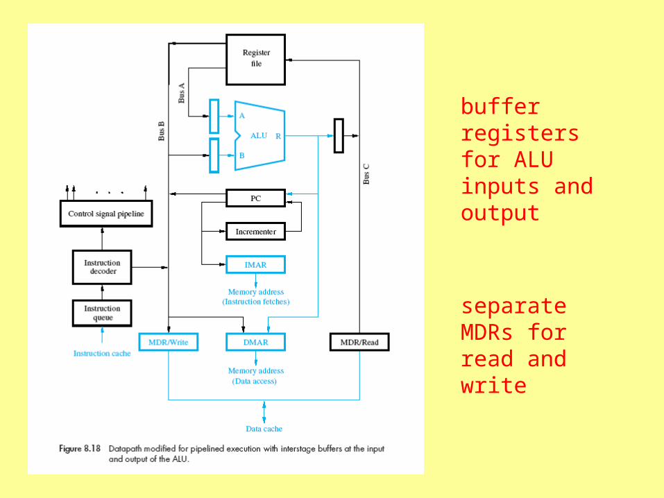
separate MDRs for read and write
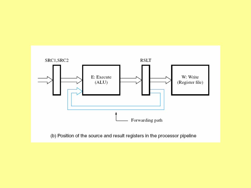
buffer registers for ALU inputs and output

buffering for control signals following Decode and Execute
instruction queue loaded directly from cache

Can perform simultaneously in any combination:
Reading an instruction from instruction cache
Incrementing the PC
Decoding an instruction
Reading from or writing into data cache
Reading contents of up to two registers from the register file
Writing into one register of the register file
Performing an ALU operation
Superscalar Operation
• Pipelining fetches one instruction per cycle, completes one per cycle (if no hazards)
• Adding multiple processing units for each stage would allow more than one instruction to be fetched, and moved through the pipeline, during each cycle
Superscalar Operation
• Starting more than one instruction in each clock cycle is called multiple issue
• Such processors are called superscalar

a processor with two execution units

instruction queue and multiple word moves enables fetching n instructions

dispatch unit capable of decoding two instructions from queue
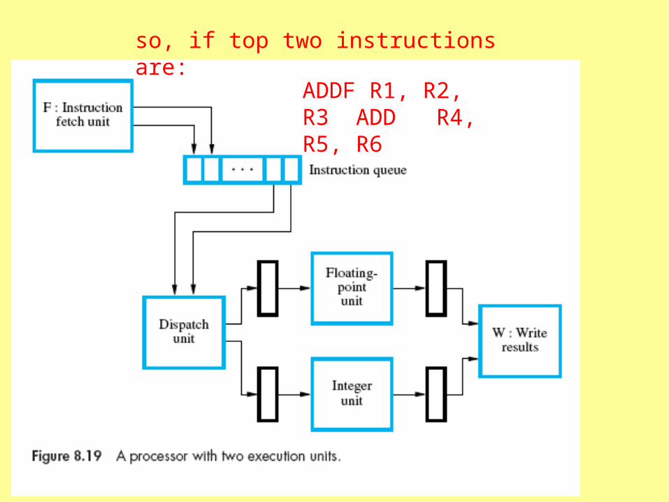
so, if top two instructions are:
ADDF R1, R2, R3 ADD R4, R5, R6
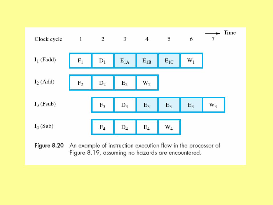
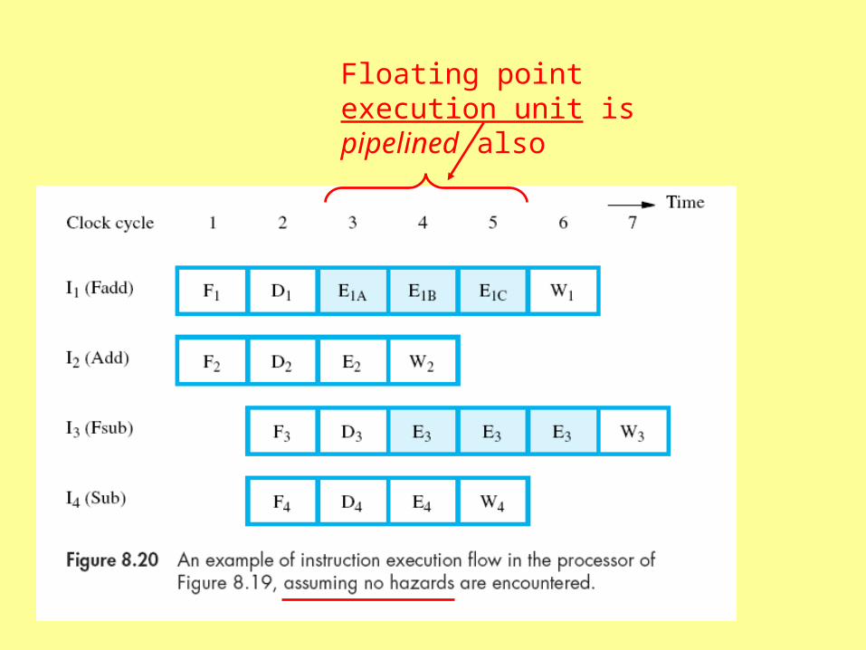
Floating point execution unit is pipelined also
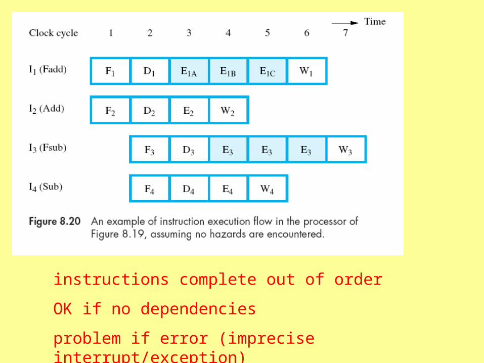
instructions complete out of order
OK if no dependencies
problem if error (imprecise interrupt/exception)

imprecise interrupt
error occurs here
later instructions have already completed!
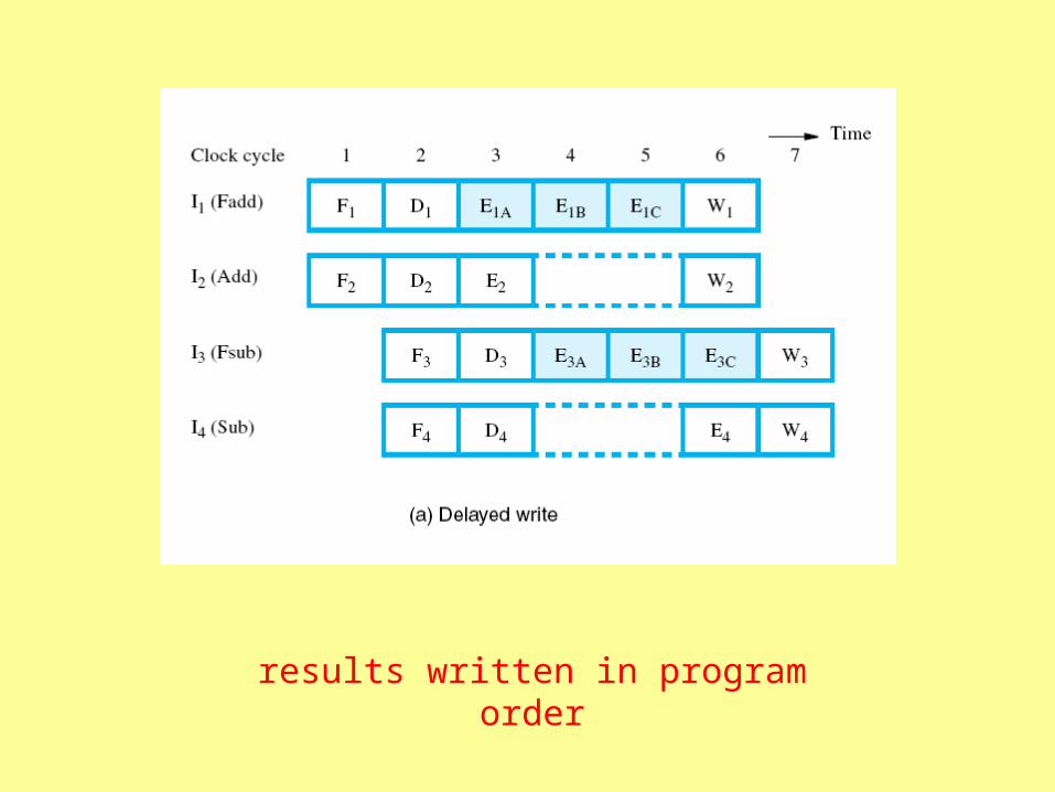
results written in program order
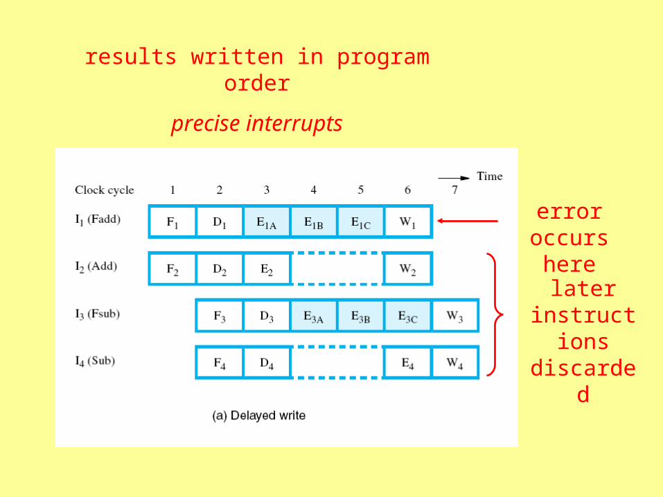
error occurs here
later instructions discarded
results written in program order
precise interrupts

temporary registers allow greater flexibility

register renaming
ADD R4, R5, R6
would write to R6
writes to another register “renamed” as R6, used by subsequent instructions
using that result

R0
R1
R2
.
.
.
Rn
0
1
2
.
.
.
n
the “architectural”
registers
the physical registers
changeable mapping
register renaming
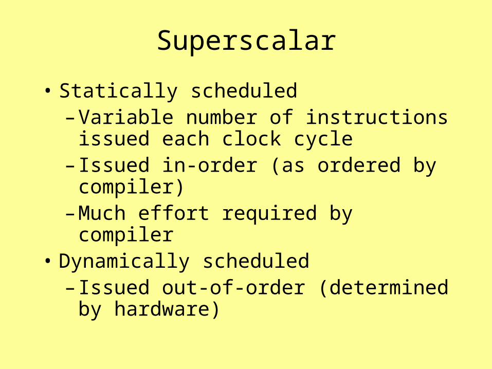
Superscalar
• Statically scheduled– Variable number of instructions
issued each clock cycle– Issued in-order (as ordered by
compiler)– Much effort required by compiler
• Dynamically scheduled– Issued out-of-order (determined by
hardware)
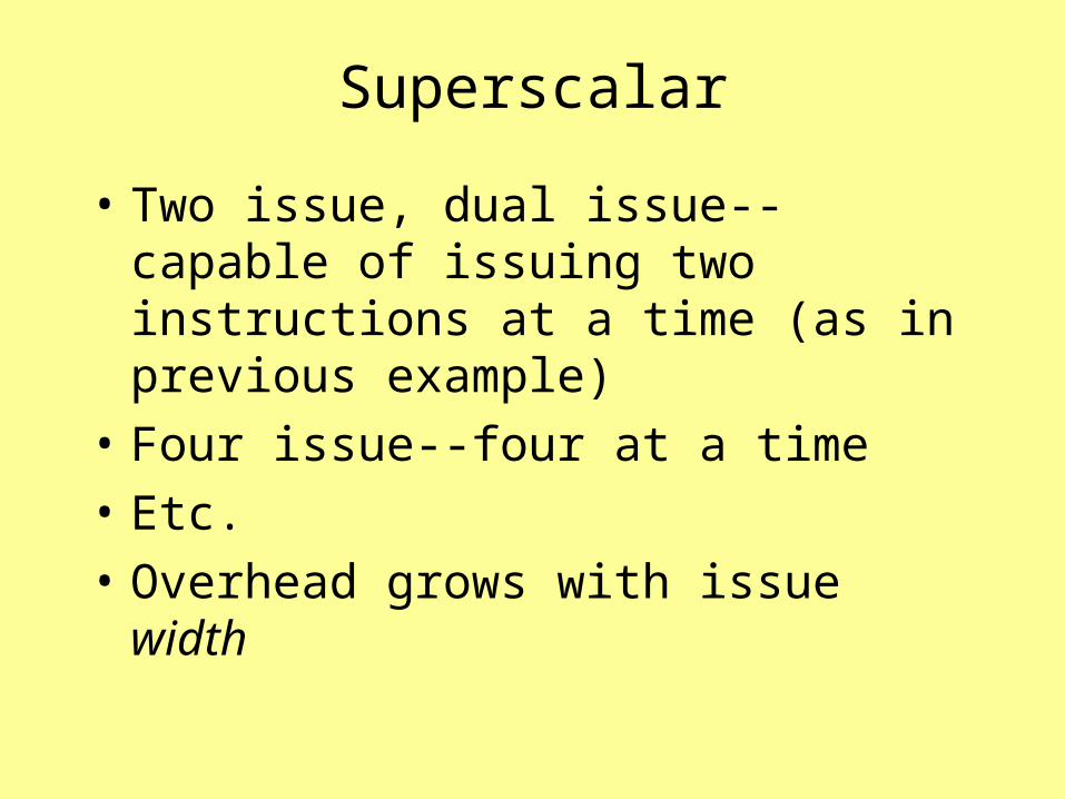
Superscalar
• Two issue, dual issue--capable of issuing two instructions at a time (as in previous example)
• Four issue--four at a time
• Etc.
• Overhead grows with issue width
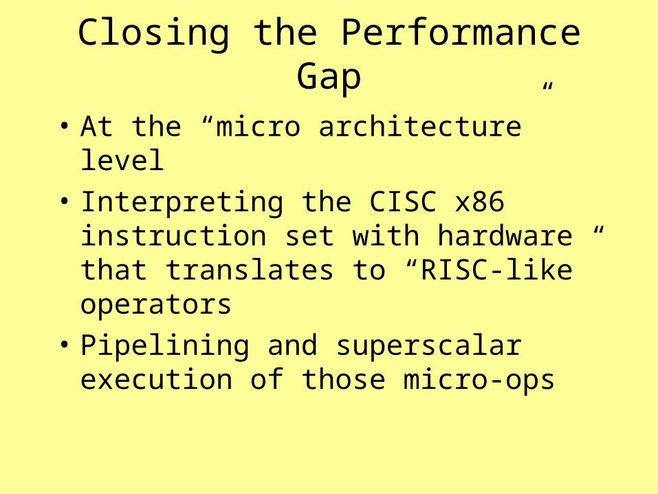
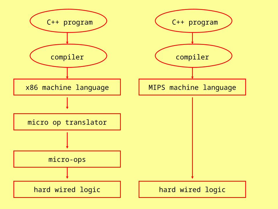
Closing the Performance Gap
• At the “micro architecture” level
• Interpreting the CISC x86 instruction set with hardware that translates to “RISC-like” operators
• Pipelining and superscalar execution of those micro-ops
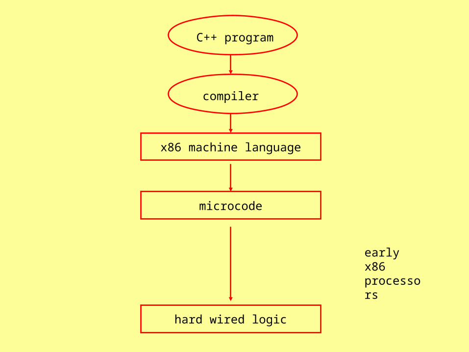
microcode
compiler
x86 machine language
C++ program
hard wired logic
early x86 processors
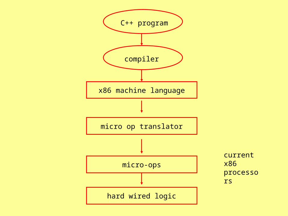
micro op translator
compiler
x86 machine language
C++ program
micro-ops
hard wired logic
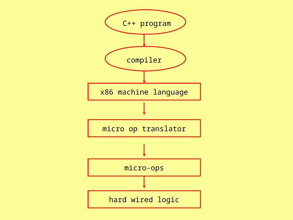
current x86 processors
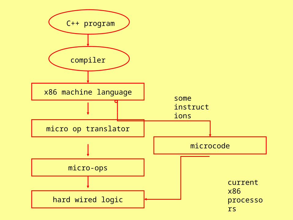
micro op translator
compiler
x86 machine language
C++ program
micro-ops
hard wired logic
microcode
current x86 processors
some instructions
micro op translator
compiler
x86 machine language
C++ program
micro-ops
hard wired logic
compiler
MIPS machine language
C++ program
hard wired logic
micro op translator
compiler
x86 machine language
C++ program
micro-ops
hard wired logic
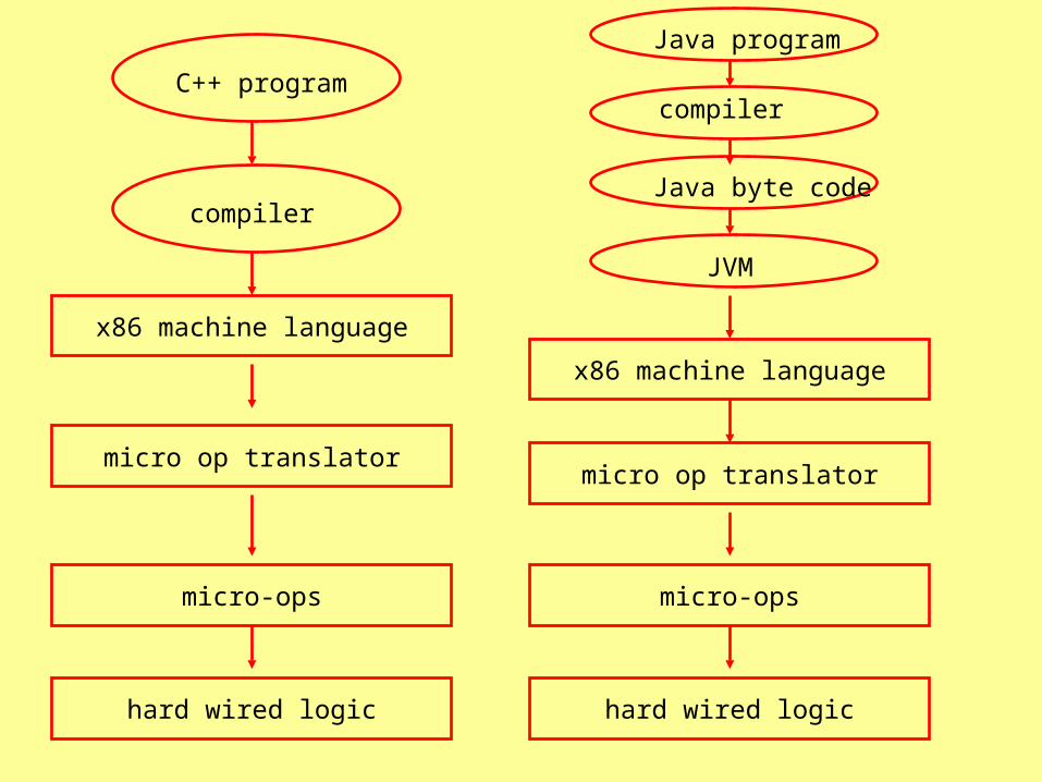
micro op translator
compiler
x86 machine language
Java program
micro-ops
hard wired logic
JVM
Java byte code
micro op translator
compiler
x86 machine language
C++ program
micro-ops
hard wired logic