CHAPTER 7 - STEEL REINFORCEMENT - · PDF fileCHAPTER 7 - STEEL REINFORCEMENT ... Spacing of...
8
Steel Reinforcement 7-1 CHAPTER 7 - STEEL REINFORCEMENT DS Temple 7.1 SCOPE This section covers the inspection of steel reinforcement to be used in the works as per the applicable chapter of the Specifications. It also covers the special attention which must be given by the engineer’s monitoring staff to material requirements, placing, fixing, cover and supports, coupling and welding of reinforcement. 7.2 MATERIALS The monitoring staff should ensure that the contractor submits a certificate of compliance for each type and batch of steel reinforcement used on the works. 7.3 INSPECTION The monitoring staff should take cognizance of the following in the inspections of the reinforcement. 7.3.1 Storage of Materials The reinforcement delivered to site should be stored neatly in a location specially prepared for this purpose. Reinforcement should be stored on a platform off the ground to prevent corrosion and contamination due to deleterious matter (mud, grease, oil, paint, loose rust, etc). If the reinforcement is to be stored for a long period of time or where stored in a marine environment (within 10km of sea) the reinforcement piles should be covered. Photo 7.1: Very poor storage of reinforcement 7.3.2 Condition of Reinforcement The condition of the reinforcement should preferably be checked in the storage yard before delivery to the point of use. The reinforcement should be clean and free of all deleterious matter and cleaned by means of water jetting, degreasing or other method if required as the presence of the above will have an adverse effect on the bond of reinforcement to concrete.
Transcript of CHAPTER 7 - STEEL REINFORCEMENT - · PDF fileCHAPTER 7 - STEEL REINFORCEMENT ... Spacing of...

Steel Reinforcement 7-1
CHAPTER 7 - STEEL REINFORCEMENT
DS Temple
7.1 SCOPE
This section covers the inspection of steel reinforcement to be used in the works as per the applicable
chapter of the Specifications. It also covers the special attention which must be given by the
engineer’s monitoring staff to material requirements, placing, fixing, cover and supports, coupling and
welding of reinforcement.
7.2 MATERIALS
The monitoring staff should ensure that the contractor submits a certificate of compliance for each type and batch of steel reinforcement used on the works.
7.3 INSPECTION
The monitoring staff should take cognizance of the following in the inspections of the reinforcement.
7.3.1 Storage of Materials
The reinforcement delivered to site should be stored neatly in a location specially prepared for this purpose. Reinforcement should be stored on a platform off the ground to prevent corrosion and
contamination due to deleterious matter (mud, grease, oil, paint, loose rust, etc).
If the reinforcement is to be stored for a long period of time or where stored in a marine environment
(within 10km of sea) the reinforcement piles should be covered.
Photo 7.1: Very poor storage of reinforcement
7.3.2 Condition of Reinforcement The condition of the reinforcement should preferably be checked in the storage yard before delivery to
the point of use. The reinforcement should be clean and free of all deleterious matter and cleaned by
means of water jetting, degreasing or other method if required as the presence of the above will have
an adverse effect on the bond of reinforcement to concrete.
Steel Reinforcement 7-2
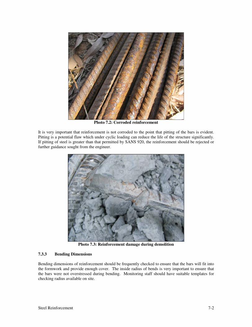
Photo 7.2: Corroded reinforcement
It is very important that reinforcement is not corroded to the point that pitting of the bars is evident.
Pitting is a potential flaw which under cyclic loading can reduce the life of the structure significantly. If pitting of steel is greater than that permitted by SANS 920, the reinforcement should be rejected or
further guidance sought from the engineer.
Photo 7.3: Reinforcement damage during demolition
7.3.3 Bending Dimensions
Bending dimensions of reinforcement should be frequently checked to ensure that the bars will fit into
the formwork and provide enough cover. The inside radius of bends is very important to ensure that
the bars were not overstressed during bending. Monitoring staff should have suitable templates for checking radius available on site.

Steel Reinforcement 7-3
The minimum radii of bends are:
• High Tensile Steel = 3 Bar diameters
• Mild Steel = 2 Bar diameters
7.3.4 Placing and Fixing
Placing and fixing of reinforcement into the forms for the structure is one of the most important aspects of the construction of a structure. Special care should be taken by the monitoring staff to
ensure that the reinforcement is placed and fixed in accordance with the design by verifying the
following:
(a) Type of steel (R or Y)
(b) Diameter of bar
(c) Bar mark
(d) Spacing of bars
(e) Concrete cover (refer to item 7.3.5 below)
(f) Laps as per drawing (refer to designer if in doubt)
(g) Grouping of bars to create space for placing and vibrating concrete.
(h) All reinforcement should be adequately tied together and properly supported to ensure that the reinforcement does not displace and move in position during the concreting process as
this will affect the cover to bars and the effective functioning of the concrete member.
(i) Adequacy of stools and clips provided (need for stools where not provided).
(j) Where bars are detailed to project out of a member (such as parapet anchors) they must be
accurately placed and held in position.
General neatness of the fixed reinforcement in the forms is
always an indication of the accuracy of the placing and fixing
and the contractor should be required to carry out corrective
actions until the cages of reinforcement are fixed properly.
7.3.5 Cover and Supports
The minimum cover requirements are usually given on the drawings and/or in the project
specifications.
When checking the placing and fixing of reinforcement the monitoring staff must pay special attention
to ensure that the specified cover to reinforcement is achieved. Cover has the most significant effect
on the long term durability of reinforced concrete and therefore of the structure.
Excess cover should be avoided as micro cracking due to bending stress can result in the growth and
development of cracks and resulting corrosion of reinforcement or member loss due to spalling. The
correct cover is required to ensure that reinforced concrete members meet their specified design
requirements.
WARNING Lack of cover on parapet
anchors/starter bars results in
loss of durability, pop outs and
corrosion of reinforcement
WARNING Do not allow the use of heating
to bend reinforcement.

Steel Reinforcement 7-4
Photo 7.4: Insufficient cover to reinforcement
cage in forms
Photo 7.5: Correct cover blocks in place
In order to ensure that the reinforcement does not move during concreting the Specifications give
specific requirements for the types and specifications of spacer blocks and stools and these requirements should be strictly adhered to.
Photo 7.6 (a) & (b): Reinforcement corroding due to lack of cover

Steel Reinforcement 7-5
Special attention should be given to the cover blocks and their mix design. Samples of cover blocks should be submitted by the contractor to the engineer for approval before the work commences. Care
should be taken to ensure that the cover blocks are made in such a way that they integrate with the
parent concrete. Only concrete cover blocks as specified in the Specifications may be used.
Photo 7.7: Failure of member due to too much cover
Photo 7.8: Corroded reinforcement resulting in loss of concrete
Stools are not necessarily detailed on the
drawings. They must be robust enough to
perform well under concreting and other superimposed construction loads. The engineer
has the authority to order the contractor to add
additional stools to ensure the reinforcement is
fixed securely and does not swivel or move
during concreting. The provision of concrete
cover to reinforcement stools should be checked.
WARNING A wide range of plastic cover blocks are
available but owing to problems associated with their use, are not permitted by a number
of road authorities. If permitted they should
only be used with great caution and subject to successful trials and ongoing monitoring. This
is necessary as many are prone to bending or
buckling under load and are sometimes clearly
visible on the finished concrete surface.

Steel Reinforcement 7-6
Approved cover meters will generally be provided on site. Where specified in the project specifications, cover to reinforcement should be confirmed after casting of the concrete by the use of
electromagnetic cover meters. If the cover is substandard the engineer may instruct the contractor to
remove and reconstruct the concrete member or agree to acceptable remedial measures with the employer.
7.3.6 Laps and Joints
Laps, joints and splices should be placed as indicated on the drawings. As a general rule the lap length
should not be less than 45 times the diameter of the smaller bar at the splice or lap. The lap positions should only be moved when the casting sizes are such that the contractor makes a specific request to
do so. In all such cases any of these changes should be referred to the designer.
It is good practice for laps and splices to be staggered as indicated on the drawings. This facilitates
better placing of concrete and improved stress distribution in the concrete section, but may not be
preferred by the Contactor in terms of casting construction joints.
7.3.7 Welding
The welding of reinforcement is generally not permitted for high tensile steel as heating hot rolled bars
causes brittle fracturing of the reinforcement. In the case of cold worked deformed bars, heating
causes the reinforcement to revert to mild steel as it loses the effects of strain hardening. Welding
may be permitted on mild steel in very specific cases, which should be referred by the monitoring staff
to the engineer.
Where welding of reinforcement is specified on the drawing the monitoring staff should ensure that
the welding is carried out strictly in accordance with the Specifications and that specialized testing is
carried out as required.
7.3.8 Mechanical Couplers
Mechanical couplers may be specified where concrete members are coupled together due to staged
construction processes, or where space restrictions do not permit normal laps and splices.
The contractor should submit to the monitoring staff (for approval by the engineer) all the test certificates for the proposed proprietary products as required in the Specifications.
7.3.9 Conformance with Project Specifications
The monitoring staff must check the Project Specifications for specific requirements related to types of
reinforcement to be used, specific cover, cover block types, etc, and should ensure the compliance
thereof for the duration of the contract.
7.4 STEEL REINFORCEMENT- CONSTRUCTION MONITORING CHECK LIST
The monitoring staff should use the “Steel Reinforcement - Construction Monitoring Check List” as
far as possible to ensure the quality of the installation of steel reinforcement.

Steel Reinforcement 7-7
INDEX TO APPENDICES
7A - STEEL REINFORCEMENT

Steel Reinforcement 7-8
CONSTRUCTION MONITORING CHECKLIST
PROJECT NO. / NAME: .......................................................................................................................................
INSPECTOR’S NAME(S): ....................................................................................................................................
STRUCTURE: ........................................................... ELEMENT: ..............................................................
ACTIVITY AND DETAILS APPROVAL
SIGNED DATE Y/N N/A Comment
1. GENERAL
1.1 Storage of reinforcement
1.2 Condition of reinforcement
1.3 Bending dimensions
2. PLACING AND FIXING
2.1 Type of steel (R or Y)
2.2 Diameter of bars
2.3 Bar marks
2.4 Spacing / Number of bars
2.5 Concrete cover (general)
2.6 Laps (alternating)
2.7 Grouping of bars (clearances)
2.8 Fixing ties adequate
2.9 Spacers
2.11 Stools in place
2.12 Projecting anchor bars
2.13 Cleanliness of reinforcement
3. COVER AND SUPPORTS
3.1 Minimum cover as per drawing
3.2 Spacer block type
3.3 Spacer block positions
3.4 Spacer block spacing / Number
provided
3.5 Stool spacing / Number provided
3.6 Stool fixity
4. SPECIAL REQUIREMENTS
4.1 Welding procedure approved
4.2 Welding quality
4.3 Mechanical couplers
4.4 Coupler type approved
4.5 Installed correctly
4.6 Other special requirements
STEEL REINFORCEMENT
CHECK LIST
APPENDIX 7A